

Haier HLC24XLP2, HLC24XLPW2 Service Manual

23.6″ LEDTV Haier HLC24XLP2&HLC24XLPW2
1
Service
Service
Service
TABLE OF CONTENTS
Description Page Description Page
SAFETY NOTICE
ANY PERSON ATTEMPTING TO SERVICE THIS CHASSIS MUST FAMILIARIZE HIMSELF WITH THE CHASSIS
AND BE AWARE OF THE NECESSARY SAFETY PRECAUTIONS TO BE USED WHEN SERVICING
ELECTRONIC EQUIPMENT CONTAINING HIGH VOLTAGES.
CAUTION: USE A SEPARATE ISOLATION TRANSFOMER FOR THIS UNIT WHEN SERVICING
6.1 Main Board………..…………………...…….….......20
6.2 Power Board…..…………..………….…..…….......23
6.3 Key Board………………………..……..……….......24
6.4 IR Board…………………………..……….…….......25
7.Adjustment/FW Upgrade/EDID…………….…...……26
8.Block Diagram.…….................................................37
9.Wiring Diagram.……................................................38
10.Schematic Diagram………..……..…………….…...39
10.1 Main Board…………….…………………...….......39
10.2 Power Board………..…....…………...…..….......49
10.3 Key Board……………….………….………….......50
10.4 IR Board……………………………….……….......52
Table of Contents.......……..................................….......1
Important Safety Notice.....................................…….....2
Revision List…………………………………………………3
1.General Specification.................................………......4
2.Operating Instructions…………………….……...….......6
2.1 The Use of Remote Control…….…………...…….......6
2.2 To Use the Menus…...………………….….………......6
2.3 Front Panel Control Knobs……………….………........6
2.4 How to Connect…….…………………….…..…….......6
3.Input/Output Specification…………....................…....7
4.Mechanical Instructions……………………..................9
5.Repair Flow Chart ……………………………………….13
6.PCB Layout …………...………………………………....20

2
Important Safety Notice
Proper service and repair is important to the safe, reliable operation of all Haier Company Equipment. The service
procedures recommended by Haier and described in this service manual are effective methods of performing
service operations. Some of these service operations require the use of tools specially designed for the purpose.
The special tools should be used when and as recommended.
It is important to note that this manual contains various CAUTIONS and NOTICES which should be carefully read in
order to minimize the risk of personal injury to service personnel. The possibility exists that improper service
methods may damage the equipment. It is also important to understand that these CAUTIONS and NOTICES ARE
NOT EXHAUSTIVE. Haier could not possibly know, evaluate and advise the service trade of all conceivable ways in
which service might be done or of the possible hazardous consequences of each way. Consequently, Haier has not
undertaken any such broad evaluation. Accordingly, a servicer who uses a service procedure or tool which is not
recommended by Haier must first satisfy himself thoroughly that neither his safety nor the safe operation of the
equipment will be jeopardized by the service method selected.
Hereafter throughout this manual, Haier Company will be referred to as Haier.
WARNING
Use of substitute replacement parts, which do not have the same, specified safety characteristics might create
shock, fire, or other hazards.
Under no circumstances should the original design be modified or altered without written permission from Haier.
Haier assumes no liability, express or implied, arising out of any unauthorized modification of design.
Servicer assumes all liability.
FOR PRODUCTS CONTAINING LASER:
DANGER-Invisible laser radiations when open AVOID DIRECT EXPOSURE TO BEAM.
CAUTION-Use of controls or adjustments or performance of procedures other than those specified herein may
result in hazardous radiation exposure.
CAUTION -The use of optical instruments with this product will increase eye hazard.
TO ENSURE THE CONTINUED RELIABILITY OF THIS PRODUCT, USE ONLY ORIGINAL MANUFACTURER'S
REPLACEMENT PARTS, WHICH ARE LISTED WITH THEIR PART NUMBERS IN THE PARTS LIST SECTION OF
THIS SERVICE MANUAL.
Take care during handling the LCD module with backlight unit
-Must mount the module using mounting holes arranged in four corners.
-Do not press on the panel, edge of the frame strongly or electric shock as this will result in damage to the screen.
-Do not scratch or press on the panel with any sharp objects, such as pencil or pen as this may result in damage to
the panel.
-Protect the module from the ESD as it may damage the electronic circuit (C-MOS).
-Make certain that treatment person’s body is grounded through wristband.
-Do not leave the module in high temperature and in areas of high humidity for a long time.
-Avoid contact with water as it may a short circuit within the module.
-If the surface of panel becomes dirty, please wipe it off with a soft material. (Cleaning with a dirty or rough cloth may
damage the panel.)

3
Revision List
Version Release Date Revision Instructions Customer Model Model
A00 Sep.19,2010 Initial release
HLC24XLP2
HLC24XLPW2

4
1. General Specification
Note:
• This model complies with the specifications listed below.
• Designs and specifications are subject to change without notice.
• This model may not be compatible with features and/or specifications that may be added in the future.
Side Connectors
HDMI
Earphone Output
USB PORT
WEIGHT & DIMENSIOIN
Dimensions with Stand (W x H x D) (inch) 22.89 x 16.44 x 6.30
Dimensions without Stand (W x H x D) (inch) 22.89 x 14.84 x 2.19
Weight with Stand (lb) 10.29
Weight without Stand and Base (lb) 9.71
WALL MOUNTING
VESA-compatible wall bracket(W x H) 100 x 100 mm
Screw type Metric 4 x 10 mm
POWER
Power Consumption 65W
Standby <1W
Input 19V 3.42A(3,42A)
Audio Power 3W + 3W
Ambient Temperature 41°F ~ 95°F
Model No
HLC24XLP2&HLC24XLPW2
DISPLAY
Viewable 23.6"
Television System NTSC standard, ATSC standard (8-VSB, Clear-QAM)
Channel
Coverage
VHF: 2 through 13
UHF: 14 through 69
Cable TV: Mid band (A - 8 through A - 1, A through I),
Super band (J through W),
Hyper band (AA through ZZ, AAA, BBB),
Ultra band (65 through 94, 100 through 125)
CONNECTIONS
Rear Connectors
Tuner input (75Ω)
AV IN: AV/S-Video and L/R audio input
PC IN: D-SUB and PC Audio (Headphone mini-jack)
Supported scan rate: 640x480@60/72/75Hz, 720x400@70Hz,
800x600@56/60/72/75Hz,
1024x768@60/70/75Hz,1280x720@60Hz,
1280x768@60Hz.
Note:
1280x1024@60Hz, 1440x900@60Hz,
1680x1050@60Hz, 1920x1080@60Hz
For HLC24XLP2/HLC24XLPW2 only.
Recommended: 1920x1080@60Hz
Component Video and L/R Audio input:
Supported resolution: 480i@59.94/60Hz, 480p@59.94/60Hz,
720p@59.94/60Hz,1080i@59.94/60Hz,
1080p@59.94/60Hz
HDMI input:
Supported scan rates: 480i@59.94/60Hz,480p@59.94/60Hz,
720p@59.94/60Hz,1080i@59.94/60Hz,
1080p@59.94/60Hz
SPDIF

5
PACKAGE CONTENTS
Supplied Accessories
TV Unit x 1
Base x 1
Remote Control x 1 (with two size AAA alkaline batteries)
User Manual x 1
AC Power Cord x 1
Adaptor x 1

6
2. Operating Instructions
For this chapter, pls refer to the user manual attached with this service manual.

7
3. Input/Output Specification
3.1 Input Signal Connector
D-SUB
Pin No. Description Pin No. Description
1 Red Video 9 No Pin
2 Green Video 10 Sync Ground
3 Blue Video 11 SDA(Remote Control)
4 SCL(Remote Control) 12 Serial Data for DDC
5 Ground 13 H. Sync
6 Red Ground 14
V
. Sync
7 Green Ground 15 Serial Clock for DDC
8 Blue Ground
HDMI
Pin No. Description Pin No. Description
1
T
MDS Data2+ 11
T
MDS Clock Shield
2
T
MDS Data2 shield 12
T
MDS Clock-
3
T
DMS Data2- 13 CEC
4
T
MDS Data1+ 14 NC
5
T
MDS Data1 shield 15 SCL
6
T
MDS Data1- 16 SDA
7
T
MDS Data0+ 17 DDC/CEC Ground
8
T
MDS Data0 shield 18 +5V Power
9
T
MDS Data0- 19 Hot Plug Detect
10
T
MDS Clock+

8
3.2 Input Signal Timing
Analog RGB
VESA MODES
Horizontal Vertical
Mode Resolution Total
Nominal
Frequency
(KHz)
Sync
Polarity
Nominal
Freq.
(Hz)
Sync
Polarit
y
Nominal
Pixel Clock
(MHz)
VGA
640x480@60Hz 800 x 525 31.469 N 59.940 N 25.175
640x480@72Hz 832 x 520 37.861 N 72.809 N 31.500
640x480@75Hz 840 x 500 37.500 N 75 N 31.500
DOS 720x400@70Hz 900 x 449 31.469 N 70.087 P 28.322
SVGA
800x600@56Hz 1024 x 625 35.156 P 56.250 P 36.000
800x600@60Hz 1056 x 628 37.879 P 60.317 P 40.000
800x600@72Hz 1040 x 666 48.077 P 72.188 P 50.000
800x600@75Hz 1056 x 625 46.875 P 75 P 49.500
XGA
1024x768@60Hz 1344 x 806 48.363 N 60.004 N 65.000
1024x768@70Hz 1328 x 806 56.476 N 70.069 N 75.000
1024x768@75Hz 1312 x 800 60.023 P 75.029 P 78.750
CVT-0.92M9 1280x720@60Hz 1664 x 748 44.722 N 59.855 P 74.500
WXGA 1280x768@60Hz 1440 x 790 47.396 P 59.995 N 68.250
SXGA 1280x1024@60Hz 1688 x 1066 63.981 P 60.020 P 108.000
WXGA+ 1440x900@60Hz 1600 x 926 55.469 P 59.901 N 88.750
WSXGA+ 1680x1050@60Hz 2240 x 1089 65.290 N 59.954 P 146.250
FHD 1920x1080@60Hz 2200 x 1125 67.500 P 60.000 P 148.500
HDMI
VESA MODES
Horizontal Vertical
Mode Resolution Total
Nominal
Frequency
(KHz)
Sync
Polarity
Nominal
Freq. (Hz)
Sync
Polarity
Nominal
Pixel Clock
(MHz)
DOS 720 x 400@70Hz 900 x 449 31.469 N 70.087 P 28.322
VGA 640 x 480@60Hz 800 x 525 31.469 N 59.940 N 25.175
SVGA 800 x 600@60Hz 1056 x 628 37.879 P 60.317 P 40
XGA 1024 x 768@60Hz 1344 x 806 48.363 N 60.004 N 65
WXGA 1280 x 768@60Hz 1664 x 798 47.396 P 59.995 N 68.25
CVT-0.92M9 1280 x 720@60Hz 1664 x 748 44.772 N 59.855 P 74.5
SXGA 1280 x 1024@60Hz 1688 x 1066 63.981 P 60.02 P 108
WXGA+ 1440 x 900@60Hz 1904 x 934 55.469 P 59.901 N 88.75
WSXGA+ 1680 x 1050@60Hz 1840 x 1080 65.29 N 59.954 P 146.25
FHD 1920x1080@60Hz 2200 x 1125 67.500 P 60.000 P 148.500
1080P 1920 x 1080P 2200 x 1125 67.5 60, 148.5
720P 1280 x 720P 1650 x 750 45.00 60, 74.25
1080i 1920 x 1080i 2200 x 1125 33.75 60, 74.25
480P 720 x 480P 858 x 525 31.50 60, 27.03
480i 720 x 480i 1716 x 525 15.75 60, 13.51

9
4. Mechanical Instructions
Step1. Unscrew the 4 screws to remove the STAND ASS’Y.
Step2. Unscrew the 6 screws to remove the REAR COVER.
10
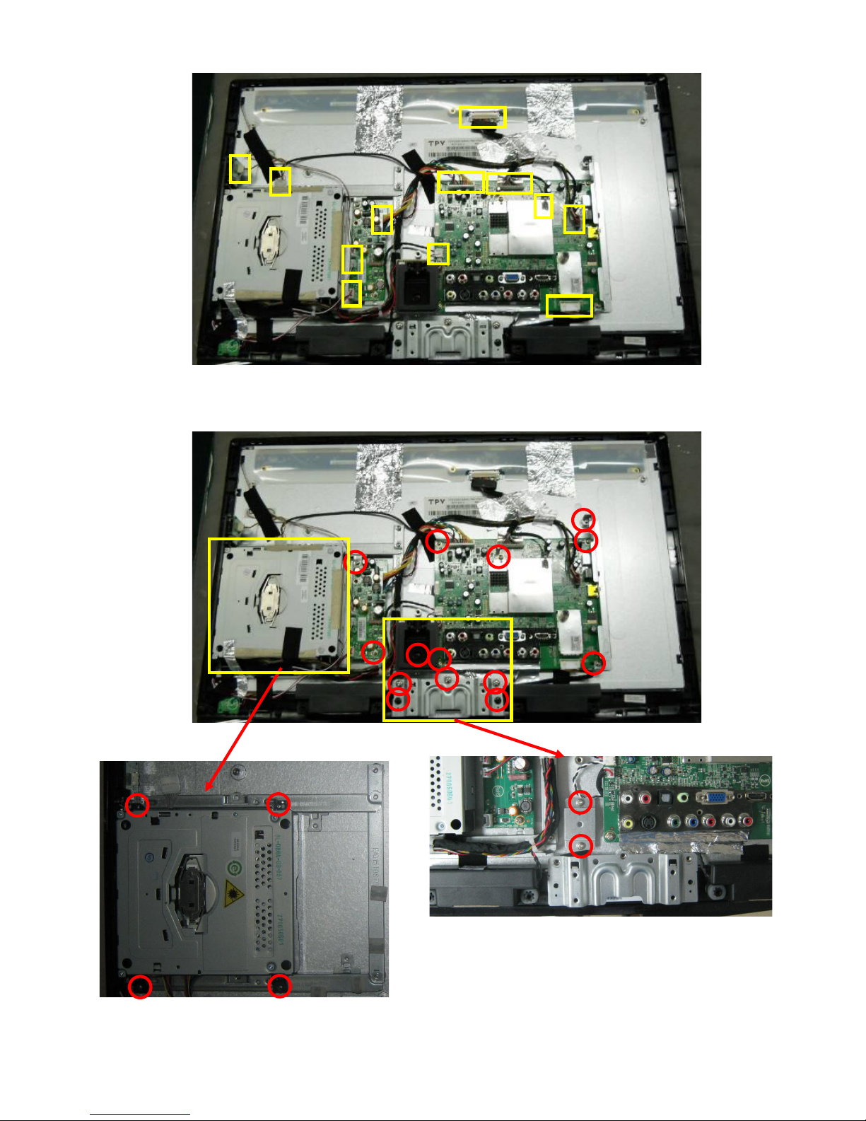
Step3. Remove the all the detachable CON/WIRES.
Step4. Unscrew the 20 screws to remove DVD, Power BD, Main BD, AC COVER, HINGE BKT and
AC BKT.

11
Step5. Unscrew the 4 screws to remove DVD-BKT-SUPPORT.
Step6. Separate the BEZEL and PANEL.

12
The PANEL.
The BEZEL.

13
5. Repair Flow Chart
1. No power
No power (LED “Off”)
Check the AC input and
the
p
ower is “ON”?
Power “On”
Check the IR board and LED
Replace the IR board
Replace the main board
Power board output=5V?
Replace the power board
No
Yes
No
Yes
No

14
2. Can’t start
Can’t start(LED red)
Replace the main board
Replace the Power board
No
Yes
No
Yes
No
No
Power board output=19V?
Check the power key is under control?
Check the IR receiver is normal?
Replace the power board
Replace the key board
Yes
Replace the IR board

15
3. Abnormal Display
Abnormal Display
Reset the source
Check the source
Check the panel
Replace the main board
Replace the LVDS cable
Replace the panel
No
No
No
Yes
Yes
Yes
No
No
Check the main board
Enter factory mode to do
“EEPROM initial”&“Reset”
Check the LVDS cable

16
4. No display
Check the B/L
signal is available?
Replace main board
Replace the power board
Panel Vcc = 5V?
Replace the Panel
No display (LED white)
Replace the main board
Check the backlight is
“On”?
Check the LVDS cable
Reinsert or replace the
LVDS cable
Replace the main board
Replace the Panel
No
Yes
Yes
No
Yes
No
No
Yes
Yes
No
Yes
No
Power board output=19V?
Check TV is under control and power
on/off by remote control and power key?
 Loading...