

Haier HB3600VA1M20, HB3000VA1M20, HB2400VA1M20 Owner’s Manual
10 to 12 SEER 2 to 3.5 Tons
HB2400VA1M20 HB2400VC1M20
Installation & Operation Manual
Air Handler
E
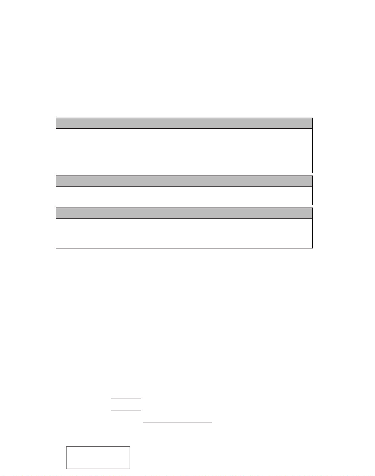
WARNING
WHEN THIS APPLIANCE IS INSTALLED IN AN ENCLOSED AREA, SUCH AS
A GARAGE OR UTILITY ROOM, WITH ANY CARBON MONOXIDE PRODUCING
DEVICES (i.e. AUTOMOBILE, SPACE HEATER, WATER HEATER,ETC.) INSURE
THAT THE ENCLOSED AREA IS PROPERLY VENTILATED.
WARNING
CARBON MONOXIDE (REFERED TO AS CO) CAN CAUSE PERSONAL INJURY
OR DEATH
WARNING
FAILURE T O FOLLOW THESE INSTRUCTIONS, LOCAL CODES OR NATIONAL
CODES MAY CAUSE FIRE, EXPLOSION, ELECTRICAL SHOCK, PERSONAL
INJURY OR PROPERTY DAMAGE.
FOLLOW ALL LOCAL CODES. IN THE ABSENCE OF LOCAL CODES REFER TO :
NATIONAL ELECTRICAL CODE NFPA 70
NFPA 90A & 90B
UNIFORM MECHANICAL CODE
READ THESE INSTRUCTIONS COMPLETELY BEFORE ATTEMPTING TO INSTALL
OR SERVICE THIS APPLIANCE.
ONLY FACTORY AUTHORIZED KITS OR ACCESSORIES SHOULD BE USED WHEN
INSTALLING OR MODIFYING THIS APPLIANCE, UNLESS OTHERWISE NOTED IN
THESE INSTRUCTIONS.
SOME LOCALITIES MAY REQUIRE THE INSTALLER/SERVICER TO BE LICENSED.
IF IN DOUBT CONTACT YOUR LOCAL AUTHORITIES.
These instructions should be retained and kept adjacent to the unit for future reference.
MODEL # HB 00VA1M20
MODEL # HB 00VC1M20
INSTALLATION DATE
The information contained in this booklet is subject to change without notice.
No. 0010572323
HB3000VA1M20 HB3600VA1M20
Models:

INDEX
TOPIC PAGE
General
Physical dimensions
Replacement Parts Source
Installation Requirements
Air Flow Orientation
Horizontal Left-Hand Instructions
Downflow Instructions
Refrigerant Tubing
Condensate Removal
Electrical Connections
Thermostat Wiring
Orifice Change
Circulating Air Duct
Blower Performance
Start-up
Regular Maintenance
Model Number Explanation
The United States Environmental Protection Agency (EPA) has issued various regulations
regarding the introduction and disposal of refrigerants introduced into this unit.Failure to follow
these regulations may harm the environment and can lead to the imposition of substantial fines.
These regulations may vary due to the passage of new laws, it is recommended that any work
on this unit be done so by a certified technician. Should questions arise contact the local EPA
office.
THIS APPLIANCE IS NOT APPROVED FOR OUTDOOR INSTALLATION
THIS APPLIANCE IS NOT TO BE USED AS A CONSTRUCTION HEATER
GENERAL
This appliance was designed certified and must be installed in accordance with published
codes.In the absence of local codes please refer to the following codes:
NFPA 90A NFPA 90B
National Electrical Code NFPA 70
Uniform Mechanical Code
Prior to shipment, this appliance was tested and inspected for damage at the factory.Unpack
carefully and if damage is found, report it immediately to the transportation company.
This appliance is approved for installation in alcoves, basements, attics or crawlway, and is
designed for connection to air distribution ductwork.
2
2
3
4
4
5
6
7
8
8
9
10
12
12
13
14
14
15
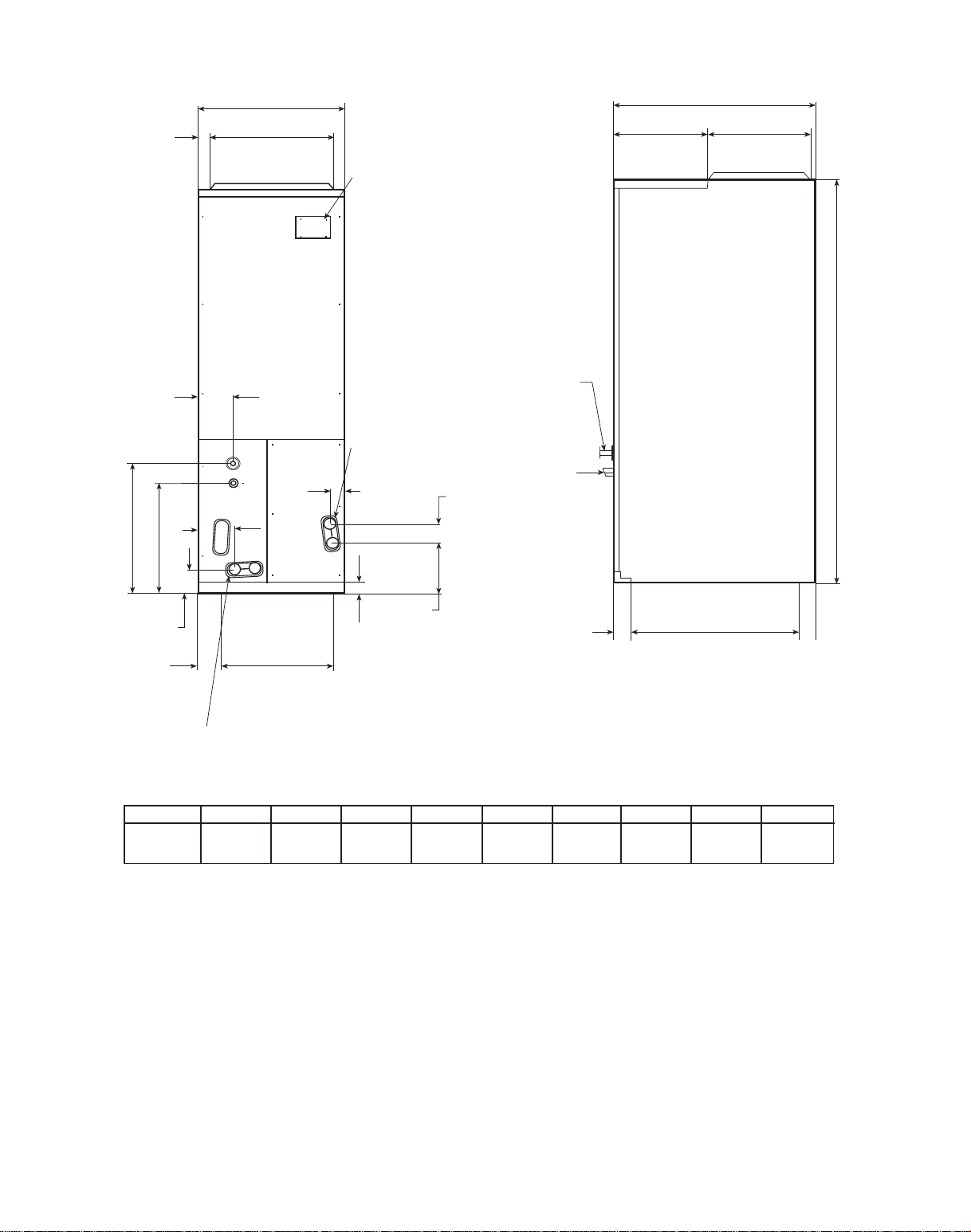
D
C
1"
[2.54 cm]
PLASTIC BREAKER COVER
PRIMARY & SECONDARY
CONDENSATE DRAINSHORIZONTAL 3/4" NPT
2"
[5.1 cm]
3.3"
[8.3 cm]
2"
[5.1 cm]
TYPICAL
F
K
G
1.1"
[2.9 cm]
5"
[12.7 cm]
H
2.4"
[ 6 cm]
1.2"
[3 cm]
INLET
FRONT VIEW
PRIMARY & SECONDARY
CONDENSATE DRAINSUPFLOW 3/4" NPT-FEMALE
1"
[2.54 cm]
J
INLET
RIGHT SIDE VIEW
LIQUID LINE
SUCTION LINE
A
B
E
11"
[29 cm]
PHYSICAL DIMENSIONS
A B C D E F G H J K
46.7 22 18.3 19.7 10 14.5 11.9 17.1 19.8 3.4
[118.7cm] [55.9cm] [46.4cm] [50.0cm] [25.4cm] [36.8cm] [30.3cm] [43.5cm] [50.3cm] [8.6cm]
3

REPLACEMENT PARTS SOURCE
Replacement parts are available through local distributors.When ordering replacement parts, give
the COMPLETE model and serial numbers shown on the rating plate.
INSTALLATION REQUIREMENTS
Before installing this appliance insure that it is properly sized and adequate power is available.
This appliance can be installed in the vertical or right horizontal position without modification.
The horizontal left and downflow positions require product modification.
This product is designed for zero inch (0") clearance; however, adequate access for service or
replacement must be considered without removing permanent structure. This unit can be
installed on a platform when deemed necessary.
In an attic installation a secondary drain pan must be provided by the installer and placed
under the entire unit with a separate drain line properly sloped and terminated in an area
visible to the owner. This secondary drain pan is required in the event that there is a leak or
main drain blockage. Closed cell insulation should be applied to the drain lines in unconditioned
spaces where sweating may occur.
Appliances installed in garages, warehouses or other areas where they may be subjected to
mechanical damage must be suitably guarded against such damage by installing behind
protective barriers, being elevated or located out of the normal path of vehicles. When
installed on a base, the base must also be protected by similar means.
Heating and cooling equipment located in garages, which may generate a glow, spark or flame
capable of igniting flammable vapors, must be installed with the ignition source at least 18"
above the floor level.
When more than one appliance is installed in a building, permanently identify the unit as to
the area or space serviced by that applice.
4
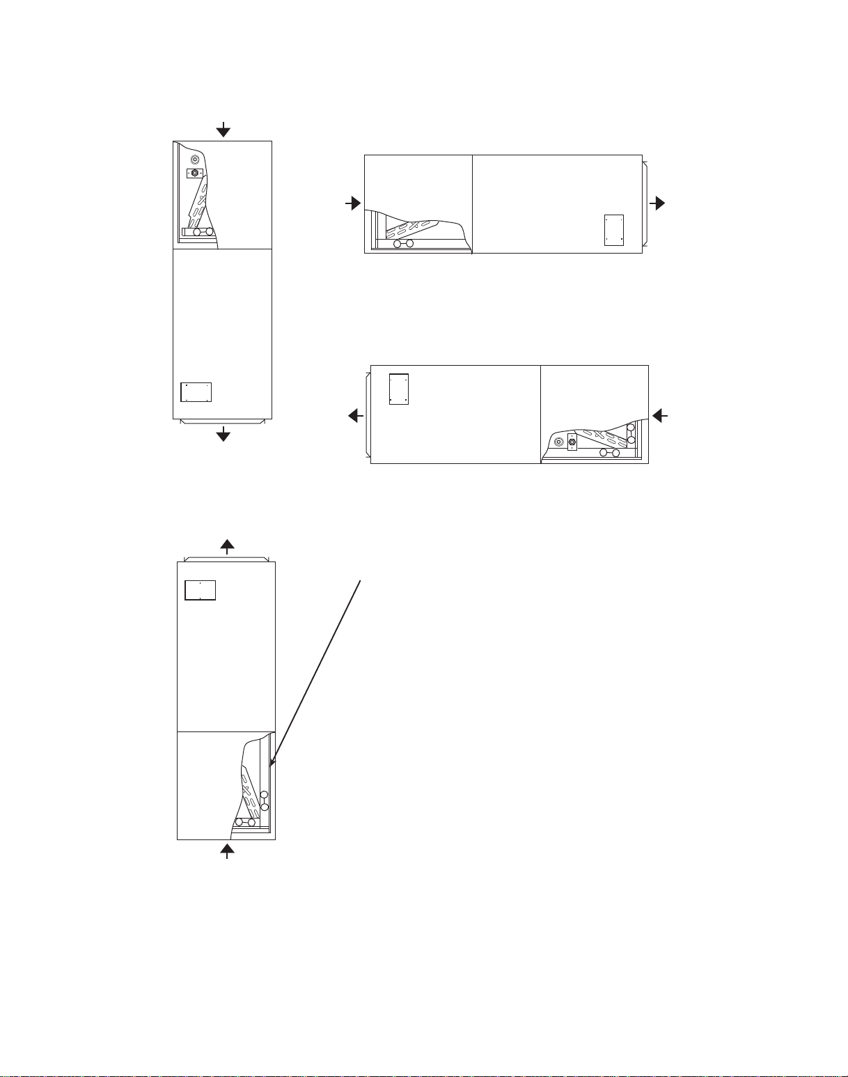
AIR FLOW ORIENTATION
Downflow discharge
(with plastic vertical
pan only) (see page 7)
*Horizontal Right Discharge
Tube and Drain conn. front
Horizontal Left Discharge
Tube and Drain conn. front
(see page 6)
Important:
Remove the horizontal pan when
unit is installed in unconditioned
i.e. (Garage, Attic ) application,
or downflow applications, and
install insulation kit on vertical
( donut shape ) drain pan.
*Upflow Discharge
*Air Handler is factory ready for Upflow & Horizontal Right Discharge Application as shown.
5
 Loading...