

Haier A2FE635CFJRU, C2FE636CWJRU, C2FE637CXJRU, C2FE636CFJRU, A2FE637CXJRU Service Manual
...
Order No.Ref0902S006V0
◎2009(HAIER ELECTRICAL APPLIANCES COR. LTD)
All right reserved. Unauthorized copying and distribution is a violation of law。
SERV ICE MANUAL
MODEL: A2FE635CFJRU
C2FE636CWJRU
C2FE636CFJRU
C2FE636CSJRU
A2FE637CXJRU
C2FE637CXJRU
This service information is designed for experienced repair technicians
only and is not designed for use by the general public. It does not contain
warnings and cautions to advice non-technical individuals of potential
dangers in attempting to service a product. Product powered by electricity
should by serviced or repaired only by experienced professional
technicians. Any attempt to service or repair the product or products dealt
with in this service information by anyone else could result in serious injury
or death.
WARNING

SERVICE MANUAL
Model:
2
Issue
Rev.
Contents
Table of Contents ··········································································································· 1
1. General Information ·································································································· 4
1-1.General guidelines ······························································································ 4
1-2. Important notice·································································································· 4
1-3. How to read this Service Manual ········································································ 6
2. Product Feature ········································································································ 7
2-1. Specifications ·········································································································· 7
2-2. External views ········································································································· 11
2-3. Major features ·········································································································· 14
3.Installation, adjustments and maintenance ···························································· 15
3-1. Door (Refrigerator door, Freezer door) ···································································· 15
3-2.Adjustable foot ·········································································································· 18
3-3. Maintenance ······································································································· 18
4. Disassembly ·············································································································· 20
4-1. A2FE635CFJRUFreezer door assembly ································································· 20
4-2. Display screen assembly ···················································································· 21
4-3. Air passage assembly ························································································ 21
4-4. Compressor assembly························································································ 23
4-5. Disassembly method of heating wire for defrosting ············································ 24
5. Control and display system ····················································································· 25
5-1. Control and display panel ························································································ 25
5-2. Function adjustment ··························································································· 25
5-3. Error code display and sensor positions ···························································· 28
6. Control principle of electronic component ···························································· 32
6-1. Fan cooling system ·································································································· 32
6-2. Ice maker system ······························································································· 32
6-3. Defrost function ·································································································· 32

SERVICE MANUAL
Model:
3
Issue
Rev.
6-4. Electromagnetic valve ························································································ 33
7. System flow principle ······························································································· 34
7-1. Refrigeration flow chart ····················································································· 34
7-2. Refrigeration flow scenograph ·········································································· 35
7-3. Air flow scenograph ·························································································· 36
7-4. Water supply flow scenograph ·········································································· 36
8. Circuit diagram·········································································································· 37
8-1. Brief principle diagram ······················································································ 37
8-2. Main control PCB diagram ················································································ 38
9. Quick check ··············································································································· 39
9-1. Self test model ·································································································· 39
9-2. PCB checkout ································································································· 40
10. Trouble shooting····································································································· 43
10-1.Abnormal phenomena ·····················································································43

SERVICE MANUAL
Model:
4
Issue
Rev.
Chapter 1 General Information
1-1. General Guidelines
When servicing, observe the original lead dress. If a short circuit is found, replace all parts which
have been overheated or damaged by the short circuit. After servicing, see to it that all the protective
devices such as insulation barriers, insulation papers shields are properly installed. After servicing,
make the following leakage current checks to prevent the customer from being exposed to shock
hazards.
1) Leakage Current Cold Check
2) Leakage Current Hot Check
3) Prevention of Electro Static Discharge (ESD) to Electrostatic Sensitive
1-2. Important notice
1-2-1. Follow the regulations and warnings
Most important thing is to list up the potential hazard or risk for the service personnel to open the
units and disassemble the units. For example, we need to describe properly how to avoid the
possibility to get electrical shock from the live power supply or charged electrical parts (even the
power is off).
This symbol indicates that high voltage is present inside. It is dangerous to make any
king of contact with any inside part of this product.
This symbol indicates that there are important operating and maintenance instructions in
the literature accompanying the appliance.
1-2-2. Be careful to the electrical shock
To prevent damage which might result in electric shock or fire, do not expose this component to rain
or excessive moisture. This component must not be exposed to dripping or splashing water, and
objects filled with liquid, such as vases, must not be place on top of or above the component
1-2-3. Electro static discharge (ESD)
Some semiconductor (solid state) devices can be damaged easily by static electricity. Such
components commonly are called Electrostatically Sensitive (ES) Devices. The following techniques
should be used to help reduce the incidence of component damage caused by electro static
discharge (ESD).
1-2-4. About lead free solder (PbF)
This product is manufactured using lead-free solder as a part of a movement within the consumer
products industry at large to be environmentally responsible. Lead-free solder must be used in the
servicing and repair of this product.
SERVICE MANUAL
Model:
5
Issue
Rev.
1-2-5. Use the genewing parts (specified parts)
Special parts which have purposes of fire retardant (resistors), high-quality sound (capacitors), low
noise (resistors), etc. are used.When replacing any of components, be sure to use only
manufacture's specified parts shown in the parts list.
Safety Component
● Components identified by mark have special characteristics important for safety.
1-2-6. Safety Check after Repairmen
Confirm that the screws, parts and wiring which were removed in ordertoservice are put in the original
positions, or whether there are the portions which are deteriorated around the serviced places
serviced or not. Check the insulation between the antenna terminal or external metal and the AC cord
plug blades. And be sure the safety of that.
Insuration Test
1. Check if there is any leak of current.
2. Cut out the power supply before the repair to avoid an electrical shock hazard.
3. In the case of a live-line test, insulating gloves should be worn to avoid potential electrical
shock.
4. Confirm the rated current, voltage and capacity before testing with any kinds of instruments.
5. Watch if the upper door is open when you check something at a lower position.
6. Take out every part in the cabinet before moving the machine, especially things like panels
(e.g. glass shelf).
7. Please wear intact cotton gloves when repair any parts of the evaporator, so that scratches
by the sharp fins can be avoided.
8.
If there is a breakdown with the refrigeration system, please surrender the machine to
the service center, else the leaked refrigerant may pollute the atmosphere
.
9. The refrigerator use AC of 220~240V with a frequency of 50Hz.
10. A big fluctuation of voltage (exceed the range 220~240V) may cause a start failure of the
refrigerator, a burn-out of the control panel and compressor, or an abnormal sound from the
compressor in operation. In this condition an automatic voltage regulator over 750W should be added.
11. Take care not to damage the supply line. Don’t yank at the line; pull the plug out gently from
the receptacle. Don’t press the line under the cabinet or step on it. Take care not to roll on or damage
the supply line when moves the machine from the wall.
12. In the case of leakage of inflammable gases like carbon monoxide, open the door and
windows. Don’t pull out or insert the plugs of the appliance.
13. Don’t touch the refrigeration surface of the freezing compartment when the refrigerator is in
operation, especially when your hand is wet, else you may be glued to the surface.
SERVICE MANUAL
Model:
6
Issue
Rev.
14. Pull out the plug of power supply during clearance or power outage. Wait at least five
minutes to resume the power supply in order to prevent damage to the compressor caused by
continuous restart.
1-2-7. Photo used in this manual
The illustration and photos used in this Manual may not base on the finaldesignof products, which
may differ from your products in some way.
1-3. How to read this Service Manual
1-3-1. Using Icons
Icons are used to attract the attention of the reader to specific information. The meaning of each icon
is described in the table below:
Note:
A “note” provides information that is not indispensable, but may nevertheless be valuable to the
reader, such as tips and tricks.
Caution:
A “caution” is used when there is danger that the reader, through incorrect manipulation, may
damageequipment, loosedata, get an unexpectedresultorhas to restart (part of) a procedure.
Warning:
A “warning” is used when there is danger of personal injury.
Reference:
A “reference” guides the reader to other places in this binder or in this manual, where he/she will find
additional informationonaspecific topic.

SERVICE MANUAL
Model:
7
Issue
Rev.
Chapter 2 Product Feature
2-1. Specifications
Pictures
Model
A2FE635CFJRU C2FE636CFJRU C2FE636CSJRU C2FE636CWJRU A2FE637CXJRU C2FE637CXJRU
BEST GOOD GOOD GOOD
BEST GOOD
Product Properties
Product description
(Refrigerator/Freezer)
Refrigerator Refrigerator Refrigerator Refrigerator
Refrigerator Refrigerator
Type of appliance
(FS= freestanding /
BI= built-in)
FS FS FS FS
FS FS
Type of cooling
system(NF=no frost/
S=static)
NF NF NF NF
NF NF
Enegey Class A+ A+ A+ A+
A+ A+
Unit dimensions
( H / W / D)
mm 1905/595/670 1905/595/670 1905/595/670 1905/595/670
1998/595/672 1998/595/672
Total net capacity L 347 352 352 352
369 374
Climate class* SN/T SN/T SN/T SN/T
SN/T SN/T
Freezer compartment /
Star rating
4* 4* 4* 4*
4* 4*
Approvals
(VDE / TÜV / IMQ / NF
/ ÖVE / DEMKO etc.)
TÜV/GS (Rhl.) TÜV/GS (Rhl.) TÜV/GS (Rhl.) TÜV/GS (Rhl.)
- -
PCT PCT PCT PCT
PCT
PCT
Certifications
( CE / ISO 9001/2)
CE / ISO 9001 CE / ISO 9001 CE / ISO 9001 CE / ISO 9001
CE / ISO 9001 CE / ISO 9001
Rohs Y Y Y Y
Y Y
Key features
Gross capacity L 400 /400 400 400
Total net capacity L 347 352 352 352
369 374
Net capacity
refrigerator
compartment
L
201 201 201 201
223 223
My zone compartment L 47
47 47 47
47 47
Freezing capacity
kg/24h
12 12 12 12
12 12
Energy
consumption/year
kwh 348 353 353 353
376 381

SERVICE MANUAL
Model:
8
Issue
Rev.
Max storage time at
breackdown Freezer
Hours
13 13 13 13
13 13
Defrosting:
(M=manual;A=automati
c)
A A A A
A A
Ventilated fan motor in
Refrigerator
N N N N
N N
Frost free system Y Y Y Y
Y Y
Defrost water outlet Y Y Y Y
Y Y
Air circulating ventilator Y Y Y Y
Y Y
Kind of coolant
(R134a/R600a)
R600a R600a R600a R600a
R600a R600a
Foaming components
(R141b / R134a / C-P)
PU/ C-P C-P C-P C-P
C-P C-P
Technical data
Voltage / frequency V/Hz 220~240/ 50 220~240/ 50 220~240/ 50 220~240/ 50
220~240/ 50 220~240/ 50
Input power / mains
fuse minimum
W /A 120/ (DC) 120/ (DC) 120/ (DC) 120/ (DC)
120/ (DC) 120/ (DC)
Temperature range
(from>to)
°C
Refrigerator 2~8°C 2~8°C 2~8°C 2~8°C
2~8°C 2~8°C
Vegetable Crisper 2~8°C 2~8°C 2~8°C 2~8°C
2~8°C 2~8°C
My zone
(3
mode :Thaw ;Q,cool;Ch
iller)
yes/no
Y Y Y Y
Y Y
Tem -2~+3° -2~+3° -2~+3° -2~+3°
-2~+3° -2~+3°
Chiller
yes/no
Y Y Y Y
Y Y
Chiller °C -2~+3° -2~+3° -2~+3° -2~+3°
-2~+3° -2~+3°
Freezer
-16
~-24°C
-16 ~-24°C -16 ~-24°C -16 ~-24°C -16 ~-24°C
-16 ~-24°C -16 ~-24°C
Features:
(DIN 8950 resp. 8953)
Energy consumption
(EN 153) per / 24h
kWh 0.95 0.96 0.96 0.96
1.030136986 1.043835616
Cooling system:
K=Compressor /
In=Inverter compressor
In In In In
In In
Max noise level
dB(A)
40 42 42 42
40 42
Aesthetics
Colours: W=white
S=silver
B=Obsidian
X=stainless steel
F=SS looking
F F S W
x x
Cabinet / Door / Top /
Frame (w / c)
S/F/B/B S/F/B/B S/S/S/S W/W/W/W
S/x/S/S S/x/S/S
Door:
F= flat / R= rounded /
S= streamline
R R R R
R R
Inside colour W W W W
w w
Bottle compartment n° 3 3 3 3
4 4

SERVICE MANUAL
Model:
9
Issue
Rev.
Hinged (r =right l =left) /
reversible
R/R R/R R/R R/R
R/R R/R
Lock
yes/no
N N N N
N N
Freezing compartment
integrated with door
Y N N N
Y N
Shelves:
Number Fridge /
Freezer
3/ - 3/ - 3 / - 3 / -
3 / - 3 / -
Type (gr=grill / g=glass
/ p=plastic)
g g g g
g g
Colourw-white / b=blue
/ g=green / t=transpar.
t t t t
t t
Adjustable (Y=yes /
N=not)
yes/no
N N N N
Y Y
Foldable Shelf
yes/no
N N N N
Y Y
Bottle Rack
yes/no
N N N N
Y N
Drawers:
Plastic drawers (fully
freezing comp.)
n°. 2 4 4 4
2 4
half freezing comp n°.
Colour of drawer
(w=white/t=transp./g=gr
een)
w w w w
w w
Crisper:
Chiller / Meat (salad
crisper) transparent
/ white
t t t t
t t
Vegetable crisper(s)
transparent / white
t t t t
t t
Equipment &
accessories
Control panel:
Power on/off Y Y Y Y
Y Y
Interior / exterior Exterior Exterior Exterior Exterior
Exterior Exterior
Display type
Display on door Display on door Display on door Display on door
Display on door Display on door
Control Type LED LED LED LED
LED LED
Control lamps
green& yellow / white
white white white white
white white
Over temperature
alarm freezer LED /
Acoustic
- - - -
- -
Door open alarm fridge
LED / Acoustic
A A A A
A A
Fast freeze switch
/-function
Y Y Y Y
Y Y
Fast cooling Y Y Y Y
Y Y
Holiday function Y Y Y Y
Y Y
Deodorizing N N N N
N N
UV-light N N N N
N N
Icon-sliver N N N N
N N
SERVICE MANUAL
Model:
10
Issue
Rev.
Antibacteoria N N N N
N N
VC(Vitamin C,keep
fresh longer)
N N N N
N N
Interior light W
LED light
Type
Full Top Points Top Points Top Points
Top Points Top Points
Freeze pack(s) n° 2 3 3 3
2 3
ice maker N N N N
N N
Ice cube tray(s) n° 1 1 1 1
1 1
Water dispenser N N N N
N N
Water dispenser
with/without gas
N N N N
N N
Butter holder N N N N
Egg trays Y Y Y Y
Y Y
Adjustable feet front /
rear
n° 2 / - 2 / - 2 / - 2 / -
2 / - 2 / -
Castors front / rear -/x -/x -/x -/x
-/x -/x
Length of cable/incl.
plug
cm 200 200 200 200
200.000 200.000
Condenser
Backwall / Integrated /
Under
U U U U
U U
Product dimensions
Unit dimensions
( H / W / D)
mm 1905/595/670 1905/595/670 1905/595/670 1905/595/670
1998/595/670 1998/595/670
Depth Without handle mm 670 670 670 670
672 672
Depth with open door mm 1204 1204 1204 1204
1204.0 1204.0
Door open angle n° >125 >125 >125 >125
>125 >125
Crisper fully extension
with door open angle
n° >125 >125 >125 >125
>125 >125
Net weight kg 84 80 80 80
86 83
Packing dimensions
& loadability
Packing dimensions
(H / W / D)
cm 200/66.3/74.1 200/66.3/74.1 200/66.3/74.1 200/66.3/74.1
210/66.3/74.1 210/66.3/74.1
Gross weight kg 92 88 88 88
96.0 93.0
40 ' Container load pcs 54 54 54 54
54 54
40 ' HC Container load pcs 71 71 71 71
54 54
Recycling symbols
Packing materials /
Recycling simbols (RS)
RS RS RS RS RS
RS RS
Cartonweight in gr 8Kg 8Kg 8Kg 8Kg
8kg 8kg
Polystyreneweight in gr 06 1.6 Kg 1.6 Kg 1.6 Kg 1.6 Kg
1.6kg 1.6kg
Polyethylene foil
weight in gr
04 0.3 Kg 0.3 Kg 0.3 Kg 0.3 Kg 0.3 Kg 0.3 Kg
Wood weight in kg - 0.000 0.000 0.000 0.000 0.000 0.000
Service
Users instruction
(languages)
D / F / I / GB / E /
P /
NL/PL/RO/CZ/HU
D / F / I / GB / E /
P /
NL/PL/RO/CZ/HU
D / F / I / GB / E /
P /
NL/PL/RO/CZ/HU
D / F / I / GB / E / P /
NL/PL/RO/CZ/HU
RUSSIAN RUSSIAN

SERVICE MANUAL
Model:
11
Issue
Rev.

SERVICE MANUAL
Model:
12
Issue
Rev.
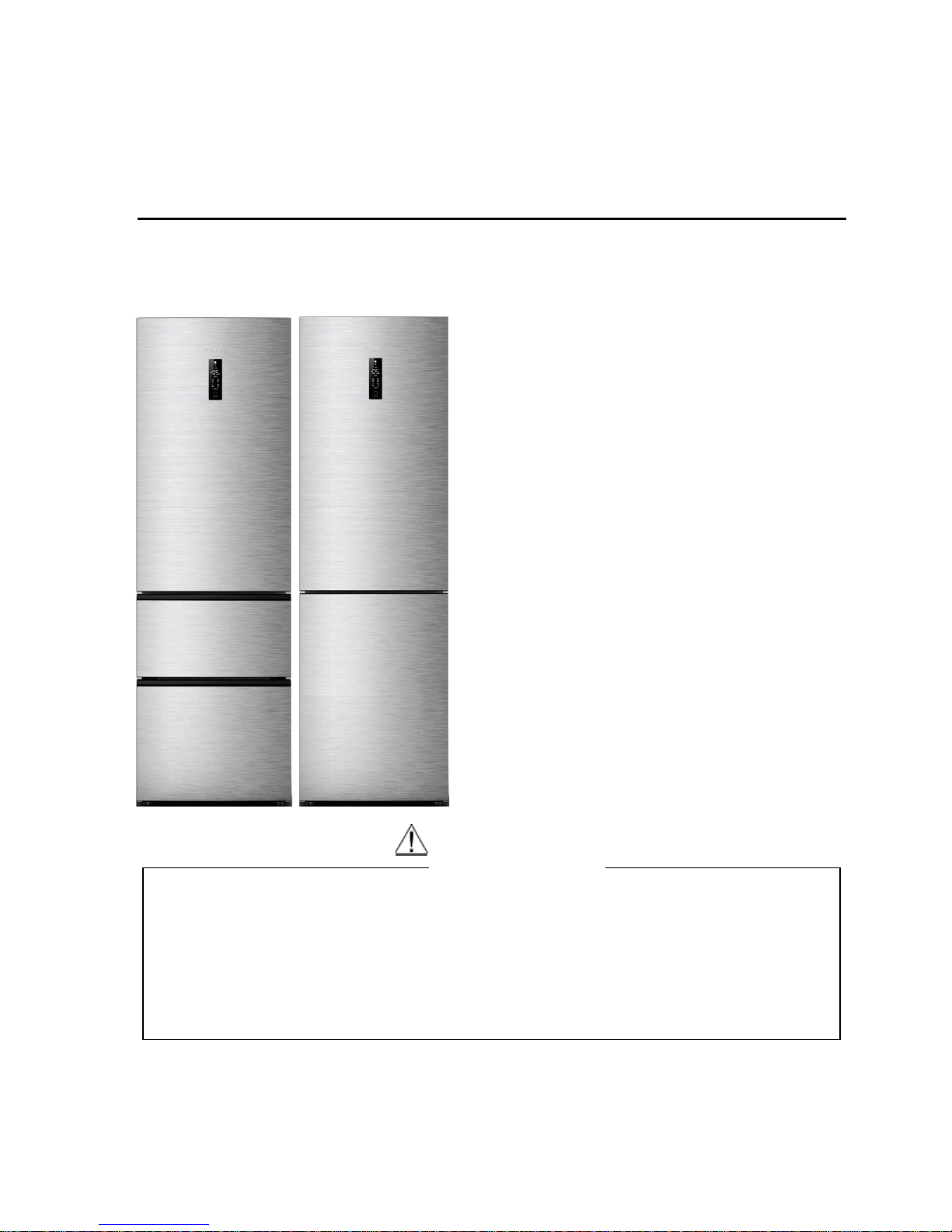
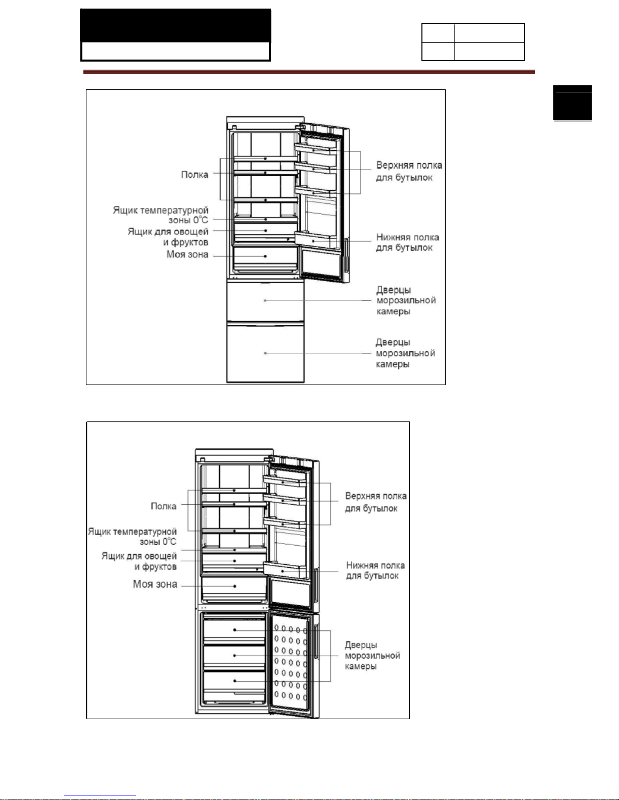
2-2. External views
2-2-1.A2FE635CFJRU
2-2-2.C2FE636CFJRU /C2FE636CSJRU/C2FE636CWJRU
SERVICE MANUAL
Model:
13
Issue
Rev.
2-2-3.A2FE637CXJRU
2-2-4.C2FE637CXJRU

SERVICE MANUAL
Model:
14
Issue
Rev.
2-3. Major features
2-3-1.Features
1. New appearance of three stainless steel doors, fashionable and luxurious, satisfies the
demands of the modern high-income families. Fully closed freezing system and drawer storage
can avoid food tainting, keep cold and are energy-saving. As warm air can't easily enter into the
storage area when opening the door.
2. Fully frequency control: it integrates the techniques of frequency conversion, de-noise,
energy-saving and quick-freezing which can benefit mutually to make better performance. The
refrigerator can automatically adjust the working efficiency of the frequency conversion
compressor by comparing the inside temperature with the setting temperature and keeps the
refrigerator in the optimized status all the time.
3. Two functions are added to the Chiller chamber: defrost(D-Frost)、quick cool(Q-Cool), when
defrost function works, the temperature of the Chiller chamber will reach to +1℃; When quick cool
function works, the temperature of the Chiller chamber is -1℃。
4. Cool wind but no frost: adopting fully air cooled refrigeration system, deep cooling and quick
freezing.
5. Quick cool function: the refrigerating chamber can be adjusted to quick cool status, after
being at this status, it will automatically turn on the function of quick cool and make the food go
through the max ice crystal zone and thus effectively reserve the nutrition.
6. Holiday function: when you are out for holiday, refrigerator will run at the low energy
consumption to make sure there's no odor in the refrigerating chamber and guarantee soft
freezing and the normal storage of frozen food.
7. LED display: adopting dynamic LED to display the operational situation of refrigerator.
8. Sliding shelf, folding bottlerack: there are designs of sliding shelf and folding bottlerack for the
refrigerating chamber to make storing and taking articles easier.
9. LED light guide plate illumination: adopting the technique of light guide plate illumination, the
light is soft, even, bright and no illumination dead angle.
10. Double-drawer freezing door body: the freezing chamber adopts the double-drawer door
body which can be opened straightly and completely. It makes storing and taking food easier. The
imported slide rail with automatic door closing device can save labor as well as electric power.

SERVICE MANUAL
Model:
15
Issue
Rev.
2-3-2.Explanation of The Models
A2 F E 7
35
PRODUCT FAMILY
COOLING
TECHNOLOGY
USER
INTERFACE CLASS
VOLUME
A1 = 3D Gen 1
F= FULL NO
FROST
M= Mechanical
9= A++++
05 = 45-54 lt
A2 = 3D Gen 2
S= DIRECT
COOLING
S= Semi
Electronical
8=A+++
14 = 135-144 lt
C1 = 2D Gen 1
T= HYBRID
E= Electronic
(= display on
the door)
7=A++
21 = 195-204 lt
C2 = 2D Gen 2
6=A+
31 = 305-314 lt
D1= Double doors Gen 1
32 = 315-324 lt
33= 325-334 lt
35 = 345-354 lt
36 = 355-364 lt
C X J
SPECIAL FEATURES COLOUR HANDLES
A = Without chiller
W = White J= Recessed/integrated
C = Chiller
T = Titanium T= External
I = Automatic Ice Device / ice maker
with water tank in the fridge
S = Silver E= Easy handles
T = ATD (Adj. T° Drawer)
X = Inox (Stainless steel)
W = Water through the door
G = Glass (Transparent
Door)
GW = Glass white
GR = Glass red
GB = Glass black
GS= Glass stainless steel
N = Black SS (VCM)
A = Aluminium SS (VCM)
B = Obsidian
F = Inox looking

SERVICE MANUAL
Model:
16
Issue
Rev.
Chapter 3 Installation, adjustments and maintenance
3-1. Door (Refrigerator door, Freezer door)
3-1-1.Removing and replacing the right door of refrigerator compartment
3-2. Water pipe
3-3. Water supplied time
A) Unscrew the four screws which secure the front panel
located at the top;
B) Push the front panel upward to withdraw the front panel;
C) Pull the hinge cover upward;
D) Disconnect the two connected terminals of electric cable;
E) Push the small cover on the right side of the front panel by
one hand to withdraw the small cover;

SERVICE MANUAL
Model:
17
Issue
Rev.
A) Remove the top hinge from the refrigerator door;
B) With the aid of pliers, unscrew and remove the
screws on the top of the hinge, then loosen and remove
the pin on the bottom of the hinge; then re-install the
A) transfer the display cable located in the slit above
the refrigerator door from left to right, always keeping
it inside the slit, and connect it to the electric cable
which is extending from the cabinet above the cabinet;
A) Click-fit the hinge cover, firstly to clip the electric
cable into the hinge cover, then clip it to the hinge;
B) install the small cover to the right side of the front
panel from bottom to top direction;
C) Click-fit the front panel from top to bottom
direction, applying pressure on several points to secure
the bottom clips being inserted into the slit of the
cross beam;
D) secure it with four screws;
E) fit the clips on the left sides(previously removed);
F) Click-fit the front panel onto the refrigerator door;

SERVICE MANUAL
Model:
18
Issue
Rev.
3-1-2.Removing and replacing the right door of freezer compartment
(For C2FE636CFJRU /C2FE636CSJRU/C2FE636CWJRU/C2FE637CXJRU)
Directions on how to dismantle and install the middle and lower hinges
⑴ Detach the 3 screws affixed to the middle hinge and remove the hinge. Unscrew the hinge
axis and then screw it from the reversed direction.
⑵ Remove the upper and lower doors separately. Dismantle the stop blocks on the bottom of
the doors. Turn them by 180 degrees and refit them on the other side.
⑶ Tilt the refrigerator to the required angle. Detach the screws fixing the lower hinge and
remove the hinge.
⑷ Fix the lower hinge to the bottom of the other side of the cabinet. Then, mount the lower door
on the lower hinge.
⑸ Take out the 3 hole plugs on the other side of the cabinet.
Turn the middle hinge by 180 degrees and install it on the other side of the cabinet. Attach the 3
screws removed in step 1. Mount the 3 hole plugs into the holes where the hinge is seated
originally.
Note: For 3-door refrigerators, the operation concerning the lower hinge is not needed.
Middle hinge
Screws affixed to
the middle hin
g
e
Middle hinge
axis
Hole plug
Screws affixed to
the lower hinge
lower hinge
Before change
Refrigerator
After change

SE
RV
Model:
3-2. Ad
Level the
placed on
foam pac
k
shorten t
h
3-3 Ma
i
3-3-1.D
e
Def
r
Thefre
Cle
a
There
f
safety,un
p
Clean
t
Drywa
t
Alway
s
Th
da
ro
cpro
D
o
si
mdet
D
m
e
Wbre
3-3-2.M
e
Even
i
ICE
M
justable
cabinet. Th
an uneven
ing materi
a
e adjustabl
e
ntenan
c
frosting a
n
ostingt
h
ezer defros
t
ning
rigerator
lugthepow
e
herefrigerat
erdroplets
o
keepthedo
o
erefrigerato
magethe fl
o
kingittoavo
i
Donotspra
y
perty.
notcleanwi
t
ilarorganic
ergent toa
v
onot touc
h
talparts.
hencleanin
g
akduetosu
d
asures o
n
nsummer,f
o
AN
U
foot
e refrigerat
o
surface, fl
a
l as a pe
d
feet of the
e
dcleaning
efreez
e
sautomatic
a
should
b
cordbefor
e
orwitha soft
ntherefrige
r
r gasketcl
e
r isvery
h
or.Keep t
h
ddamageto
or flus
h
h hardbrus
solutions
,
oiddamage
thecoldm
, donotcle
den tempe
r
power in
t
odmay be
s
AL
r should b
e
t strong an
estal. If th
e
refrigerator
r
lly. Noman
u
ecleaned
r
e
cleaningth
e
clothor spo
n
ator surfac
e
an
.
eavy.Whe
ner
efrigerat
o
the floor.
therefriger
a
h, wirebrus
acidor
a
or warm w
a
etalparts
w
anthecoldgl
aturechan
g
erruption
tored inthe
r
placed on
d fire- resis
refrigerat
o
by turning
t
al operatio
gularlytopr
e
efrigerator.
gewithwar
m
swith adry
s
youaremo
v
r uprightd
u
torwithwat
e
h, deterge
n
lkalinesolu
ter and a
m
ithwethand
ass shelv
e
eandcause
efrigerator
a flat and
s
tant materi
a
r is slightl
y
hem clock
w
nisneeded.
ventbadst
o
water(mild
oft cloth.
ingitforclea
n
ringmoving
toavoidim
p
tpowder, g
a
tions.Pleas
e
ild deturge
n
s;otherwise
y
swithwarm
w
personal in
j
f
or afewho
u
I
s
R
olid surfac
e
ls must be
unstable,
ise or antic
l
red
f
detergent
m
ingorrepair
s
.Donotmov
e
actonitsele
c
soline,am
y
cleanwith
t.
ourskinma
ater. Oth
e
ury orprop
e
rsafterapo
w
sue
ev.
. If the refr
i
used. Nev
e
you can le
n
ockwise.
oododors.
ay be add
e
,takecaren
the refrige
tricalinsula
lacetate, a
c
special r
e
ystick ont
h
rwisethegl
a
rtyloss
er interru
p
gerator is
r use the
gthen or
For
d).
ot to
rator by
tion
etoneand
frigerator
e cold
ssmay
tion. If a
19

SE
RV
Model:
poweri
Donot
p
fewtim
Ifprior
n
somei
c Asto
3-3-3.St
o
Ifthe r
e
water
s
Keept
h
badod
o
To
etur
3-3-4. B
e
Ifleavi
n
waitfo
r
anyfo
o
dropb
e
syste
m
jointbr
e
3-3-5. M
o
Unplu
g
Remo
v
Secur
e
mova
b
Donot
t
refrige
Donot
m
Ne
v
ICE
M
nterruption
o
utaddition
a
esas possi
b
oticeofapo
w
eandputitin
stemperatu
rageperiod
a
pping us
e
frigeratorw
i
ource,and
ce r
efriger
a
rs.
nsurethes
e
ned off unl
e
fore leavi
gonanexte
n
thefrostto
dremaining
i
low0oC,ple
a
.Otherwise
s
aks.
ve the re
f
therefriger
a
eallfood.
theshelves
a
leparts inth
e
iltthe
ratingsyste
m
ovethe ref
erplacethe
AN
U
ccurs, plea
s
lfoodintoth
e
le.
erinterrupt
i
acontaineri
n
eintherefri
g
ndedible q
u
llnotbeuse
d
leanitwithth
tor doorop
e
rvicelifeof
t
ss itisnece
s
ng for a h
o
ded vaca
t
melt. Aft
e
nthe comp
a
seaska
eriousprop
rigerator
tor.
ndcrisperi
n f
reezer wi
t
refrigera
t
.
igerator by
i
refrigeratin
g
AL
ecall thep
o
refrigerator
onis given
the topofth
e
eratorwill
ality offoo
d
for anexten
emethodde
s
n topreve
n
herefrigera
t
sary.
liday or v
a
ion,please
d
rwards,cle
a
rtment fro
m
ertylossma
y
thefridgest
o
h adhesive
t
ormoretha
n
tshandleto
a
horizontall
y
wercompa
n
duringap
o
andtheinte
fridgestor
a
riseduring
a
willbereduc
ded period,
cribed abo
v
tanyfoodre
or, itis re
c
cation
isconnectth
nanddryth
e
producing
qualifieds
e
becausedd
ragecomp
a
ape. Close
t
45degrees
(
voidpropert
down.
ytoaskabo
u
wer interr
u
rruptiondur
a
gecompart
m
power i
n
ed.
pleaseunpl
e.
mainingin
t
ommende
d
e powera
n
interior, a
n
badodors. I
rviceperso
n
ueto ov
e
tmentasw
e
hedoor and
angle
damageor
I
s
R
tthe interru
p
ptionandtr
y
tionis ove
r
ent.
terruptiono
r
ugthepowe
r
hecompart
m
thatthere
f
dwatersour
c
dkeepthe
f
theroomte
m
todrainthe
w
rflowofwat
e
ll asth
e
securewith
tovertic
a
personalinj
u
sue
ev.
tionduratio
n
toopen th
e
24 hours,
m
otherfailure
s
cord, disco
n
ent fromp
r
igerator n
o
e. Remo
v
dooropen
peratureis
aterinthew
a
rif thew
a
shelvesan
d
adhesiveta
p
l)toavoidd
a
ry.
.
door as
ake
,the
nect the
oducing
tbe
eanyfood;
toprevent
expected
tersupply
terpipeor
other
e.
magingthe
20

SERVICE MANUAL
Model:
21
Issue
Rev.
Chapter 4 Disassembly
4-1.A2FE635CFJRU/A2FE637CXJRU Freezer doorassembly
4-1-1. Disassembly of the freezer’s upper door body
① ②③
① Open upper drawer of the
freezer;
② Make the front-ends of the
drawer and the tray lean
upward a little according to
illustration ②;
③ Take out the drawer and
the tray from the side;
④⑤⑥⑦
④Turn the decoration caps of
the slide rail outward, and
then take off the 2 decoration
caps;
⑤ Use Phillips screwdriver to
take off the left and right
screws.
⑥ As shown in illustration ⑦,
catch and pluck the bracket
from the slide rail, , then take
off the door body;
4-1-2. Disassembly of the freezer’s bottom door body
①
②③④
①Open the bottom drawer of
freezer;
② As shown in the
illustration, make the front-end
of the tray lean upward a little,
then take off the tray from the
top;
③ As shown in illustration ④,
make the back of the drawer
lean upward, then take off the
drawer from the top;
⑤ Use Phillips screwdriver to
take off the left and right
screws.
⑥ As shown in illustration ⑦,
catch and pluck the bracket
from the slide rail, then take

SERVICE MANUAL
Model:
22
Issue
Rev.
⑤⑥⑦
off the bottom door body,;
4-2. Display screen assembly
①②③④
Press a sucker onto the
middle of the display screen
gently, and take off the display
screen from the door body of
the refrigerating chamber, and
then take apart the terminal.
4-3.Air passage assembly
4-3-1. Disassembly of the air duct of refrigerating chamber
① ②③
① Carefully take down the
lampshade;
② Use Phillips screwdriver to
take off the 2 screws on the
top of the refrigerating air
duct;
③ Unplug the terminal
connectedwith the
refrigerating air duct and take
off the refrigerating air duct.
4-3-2. Disassembly of the air duct of the chiller chamber
①②
① Use Phillips screwdriver to
take off the left and right
screws of the air duct of the
chiller chamber;
② Unplug the 2 terminals
connected with the air duct of
the chiller chamber and take
off the air duct of the chiller
chamber.
4-3-3. Disassembly of the air door

SERVICE MANUAL
Model:
23
Issue
Rev.
① ②
① Take the air duct of the
chiller chamber out of the cover
board;
② Unplug the terminal of the
air door and take off the air
door.
4-3-4. Disassembly of the air duct of the freezer
①②③④
① Use Phillips screwdriver to
take off the 5 screws of the air
duct of the freezer;
② Pull out 4 slide rails and
uplift the bottom of the air duct
slightly, make the right side
onward a little and take off the
air duct of the freezer a little;
③ Unplug the 2 terminals
connected with the air duct of
the freezer;
④ Make the air duct of the
freezer slide from the bottom.
4-3-5. Disassembly of the freezer fan
①
① Prize up the upper and
down cover boards of the
air duct of the freezer
gently from the side;
②
② Take out the fan cable,
open the claw of the fan gently
and take off the freezer fan.

SERVICE MANUAL
Model:
24
Issue
Rev.
4-4. Compressor assembly
Illustration of the compressor chamber components:
Material list:
No. Name of material Specific No. Qty.
1
Self-tapping screw 0060112284 3
2
Compressor NX1116Y(Include Capacity ) 0060702332 1
3
Supporting plate assembly of compressor 0060830615 1
4
SCREW 0060600186 1
5
Evaporating utensil 0060222122 1
6
DAMPING MAT 0060220107 1
7
Heating pipe of evaporating utensil 0060703847 1
8
POWER CORD FIXING RUBBER 0060405012 1

SERVICE MANUAL
Model:
25
Issue
Rev.
4-5.Disassembly of the heating wire for defrosting
①②③
① Take out the 2 plug
terminals connected with the
defrosting cable in the red
circles;
② As the red circle shown in
illustration ② , gently break
apart the 2 chips which are
used to fix the defrosting and
heating wire, and then get the
defrosting and heating wire to
go through the right chip;
③ Make the defrosting and
heating wire go through the
left chip.

SERVICE MANUAL
Model:
26
Issue
Rev.
Chapter 5 Control and display system
5-1. Control and display panel
5-2. Function adjustment
Fridgestorage temperaturesetup
Press key A1 repeatedly until indicators B inlluminates; press A2 to set the refrigerator
temperature. ,corresponding indicators B and D begin to flash simultaneously. The temperature
increases by 1℃ by each single press; The refrigerator setting position sequences through
“2”-“3”-“4”-“5”-“6”-“7”-“8”-“2”. The refrigerator temperature range is from a minimum value of 2℃
to a maximum value of 8℃. Stop to press A2 to confirm the set temperature.
Freezerstoragetemperaturesetup
Press key A1 repeatedly until indicators C inlluminates; press A2 to set the freezer temperature.
corresponding indicators C and D begin to flash simultaneously. The temperature reduces by 1℃
by each single press; The freezersetting sequences through “-16”- “-17”- “-18”- “-19”- “-20” -
“-21” -22”- “-23”-“-24”-“-16”. The freezer temperature ranges from a minimum value of -24℃ to a
maximum value of -16℃. Stop to press A2 to confirm the set temperature.
Supercool

SERVICE MANUAL
Model:
27
Issue
Rev.
Press key A3 repeatedly until indicators E begin to flash; press A4 to confirm the activation of the
Super Cooling function. This function can be disabled by repeating the activation procedure
manually. This function will be automatically disabled when temperature drops below minimum
level.
In this mode, the Super Cool function will be disabled by the operation of setting the refrigerator
temperature.
SuperFreeze
Press key A3 repeatedly until indicators G begin to flash; press A4 to confirm the activation of the
Super Freeze function. This function can be disabled by repeating the activation procedure
manually. This function will be automatically disabled after 56 hours.
In this mode, the Super Freeze function will be disabled by the operation of setting the freezer
temperature.
HolidayFunction
Press key A3 repeatedly until indicators I begin to flash; press A4 to confirm the activation of the
Holiday Function. This function can be disabled by repeating the activation procedure manually. In
Holiday mode, the refrigerator compartment operates at a temperature of 17℃ automatically.
In this mode, the Holiday Function will be disabled by the operation of setting the refrigerator
temperature.
My Zone Q-cool Function
Press key A3 repeatedly until indicators F begin to flash; press A4 to confirm the activation of the
My Zone Q-cool Function. This function can be automatically disabled by choosing the other
functions of My Zone box.
My Zone D-Frost Function
Press key A3 repeatedly until indicators H begin to flash; press A4 to confirm the activation of My
Zone D-Frost function. This function can be automatically disabled by choosing the other
functions of My Zone compartment.
My Zone Chiller Function
Press key A3 repeatedly until indicators J begin to flash; press A4 to confirm the activation of My
Zone Chiller Function. This function can be automatically disabled by choosing the other functions
of My Zone compartment.
Note: Among the three functions of My Zone compartment, one of the functions must be
activated.

SERVICE MANUAL
Model:
28
Issue
Rev.
DisplayControl
Thedisplayscreen willturnoff automatically 30 seconds after anoperationisfinished.Itwillbelitup by
openingthe dooror pressinganykey. (Alarmdoesnotlightupthedisplayscreen)
Door
OpeningAlarm
Whentherefrigeratordooris open formorethan3minutes, thebuzzerwillsoundbeepsall the time.
Thebuzzercanbesilencedbyclosingthedoor or pressing any keys. If the refrigerator door is left open
for over 7 minutes, the internal light automatically switches off.
Turningoff/on theRefrigerator
When the refrigerator is working, if you press key A4 for 5 seconds, the whole refrigerator will
be switched off. The buzzer will begin to beep after pressing key A3 for 5 seconds. The whole
refrigerator will stop to work after the beep.
When the refrigerator is switched off, if you press key A4 for 5 seconds, the relevant indicator
lights up, the refrigerator begins to operate.
Note: The refrigerator needs to be emptied before operating this function; this operation does
not equivalent to tuning off the power.

SERVICE MANUAL
Model:
29
Issue
Rev.
5-3. Error code display and sensor positions
When the refrigerator runs abnormally, it can enter into the mode of malfunction check by manually
adjusting the display board.
Entering method: Open the refrigerator door,after the display board is lighted, press the key of “Temp
Zone”, and at the same time press the key of “Temp Set” 5 times to enter into the mode of malfunction
code and sensor temperature display. After entering into this mode, it will display the malfunction code
in the temperature display area according to display priority level. Press the key of “Temp Set” to
display next code. After the malfunction code is displayed, every time you press the key of “Temp Set”,
it will display AT SNR, R SNR, S SNR, F SNR, D SNR practical temperatures one by one. Notes: if no
malfunction, then it will display the practical temperatures of each sensor directly after entering. The
following table shows the display methods of each sensor:
Sensor Display method Displayed icon
RT SNR
All the icons in the temperature
display area are dark.
R SNR
The R area is lighted among all
the icons in the temperature
display area.
S SNR
The R area is lighted and
flashing among all the icons in
the temperature display area.
F SNR
The F area is lighted among all
the icons in the temperature
display area.
D SNR
All the icons are lighted in the
temperature display area.

SERVICE MANUAL
Model:
30
Issue
Rev.
Notes: when checking the practical temperature of each sensor, distinguish the name of the presently
displayed sensor according to the above table. The temperature display area of “-88” displays the
integer figures of the practical temperature of the current sensor. One decimal figure of the practical
temperature is displayed through 4 functional icons as shown in the following table:
Represent
ative No.
Displayed icon Lighted
icon
Represent
ative No.
Displayed icon Lighted icon
0.0
None
0.5
S-Cool + D-Frost
0.1
S-Cool
0.6
Q-Cool + D-Frost
0.2
Q-Cool
0.7
S-Frz.+ D-Frost
0.3
S-Frz.
0.8
S-Cool + S-Frz. +
D-Frost
0.4
D-Frost
0.9
Q-Cool + S-Frz. +
D-Frost
Log-out method: after entering into this mode, press the key of “Temp Zone” again for 3seconds to log
out from this mode. If there’s no key press operation for 2minutes after entering into this mode, it will
log out automatically.

SERVICE MANUAL
Model:
31
Issue
Rev.
Correspondence table of refrigerator malfunction codes:
NO. Item Code Content
Position of
sensor
1 RT SNR error F2 RT SNR short circuit or open circuit Door body
2 R SNR error F3 R SNR short circuit or open circuit
Air duct of
refrigerating
chamber
3 F SNR error F4 F SNR short circuit or open circuit
Air duct of
freezerchamb
er
4 S SNR error F5 S SNR short circuit or open circuit
Air duct of
chiller
chamber
5 D SNR error F6 D SNR short circuit or open circuit Evaporator
6 Communication error E0
No signal,More than 2 minutes
/
7 F FAN error E1
No signal,More than 10 seconds
/
8 C FAN error E2
No signal,More than 10 seconds
/
9 Defrosting error Ed
D SNR Can’t reach 8℃,90 minutes
/

SERVICE MANUAL
Model:
32
Issue
Rev.
Graphic display of the sensor location
Name of sensors Distance to the
top (mm)
Distance to the right
side (mm)
Distance to the
left side (mm)
Environment temperature sensor
13 286 309
Refrigerating sensor
390 194 401
Freezing sensor
1270 112 483
Chiller sensor
912.5 203 392
Defrosting sensor
1275 461 134
Fridge storage
temperature sensor
Ambient
temperature sensor
Freezer storage
tem
p
erature sensor
Defrosting
temperature sensor
Chiller
temperature sensor

SERVICE MANUAL
Model:
33
Issue
Rev.
Chapter 6 Control principle of electronic component
6-1. Fan cooling system
(1)Air escaper’s open and close is controlled by fridge sensor R SNR.
(2)Air escaper is closed firstly and then opened once, then open or close of air escaper is controlled
according condition (1).
(3)If air escaper is closed more than an hour, it will be opened at a time. Then open or close of air
escaper is controlled according fridge sensor R SNR.
6-2. Ice maker system
6-3. Defrost function
Refrigerator will start defrosting for the 1st time after 8 hours of the initial operation.
After refrigerator runs normally, the refrigerator will start defrosting after 30 hours’ operation when the
environment temperature is over 28℃; or after 49hours’operation when the environment temperature
is not over 28℃.
When the refrigerator runs normally, the compressor continuously runs for 90minutes, or after
defrosting, the compressor continuously runs for 180minutes, or the air door of the refrigerating
chamber continuously opens for 60minutes, or the temperature of the freezing sensor is over -5℃ and
the temperature of the refrigerating sensor is equal or higher than the sum of the set refrigerating
temperature and 6℃, when the environment temperature is over 28℃, the refrigerator will start
defrosting after 12hours’ operation. When the environment temperature is equal or lower than 28℃,
the refrigerator will start defrosting after 25hours’ operation.
During the process of turning on the compressor, the air door of the refrigerating chamber never
reaches to the turning off point, and then the refrigerator will start defrosting after 8hours.
When the temperature of the defrosting sensor reaches to 8℃ during defrosting, the refrigerator will
log out of defrosting mode.
The compressor is stop and fridge air escaper is close when defrosting.
If the defrosting time is over 90minutes, the refrigerator will start defrosting control after 5hours’
operation, until the temperature of the defrosting sensor reaches to 8℃ in 90minutes, then the
refrigerator starts defrosting control normally.
The product can enter into defrosting mode, and exit defrosting mode after the defrosting time is more

SERVICE MANUAL
Model:
34
Issue
Rev.
than 90 minutes, when the defrosting sensor malfunction (short circuit or open circuit).
If defrosting time is more than 90 minutes and the defrosting sensor temperature can’t reach 8ºC, the
product will disconnect defrosting heater, and display ED on fridge display area under malfunction
mode until in some defrosting cycle the defrost sensor temperature reach 8 ºC.
If the product is set to enter into fast freezer or fast fridge, the icon of fast freezer or fast fridge will light,
but the defrosting process will go on, fast freezer or fast fridge mode will not execute until finishing this
defrosting cycle. The surplus defrosting time is not reckoned in the time of fast freezer or fast fridge.
6-4. Electromagnetic valve

SERVICE MANUAL
Model:
35
Issue
Rev.
Chapter 7 System flow principle
7-1. Refrigeration flow chart
The refrigeration system of direct cooling single-system cooler belongs to the category of a
single-temperature and single-control refrigerating system with one evaporators and is controlled by a
single temperature control.

SERVICE MANUAL
Model:
36
Issue
Rev.
7-2. Refrigeration flow scenograph

SERVICE MANUAL
Model:
37
Issue
Rev.
7-3. Air flow scenograph
7-4. Water supply flow scenograph
None

SERVICE MANUAL
Model:
38
Issue
Rev.
Chapter 8 Circuit diagram
8-1. Brief principle diagram
A.Power plug
B. Refrigerator sensor C. Chiller sensor D. Freezer sensor E .Defrost sensor
F.Ambient sensor G.Display panel H. Refrigerator lamp I.Hall IC J.Damper
K.Freezer Fan Motor L. Fuse1 M. Defrost Heater N. Fuse2 O. Heater near water
drain hole
P. Over load protector Q. Compressor R. PTC S.Capacitor T.Control board

SERVICE MANUAL
Model:
39
Issue
Rev.
8-2. Main control PCB diagram

SERVICE MANUAL
Model:
40
Issue
Rev.
Chapter 9 Quick check
9-1. Self test model
Entering method of TEST function: Open the refrigerator door,press the keys of “Func.Set” and “OK” at
the same time, press the key of “OK” and press the key of “Func.Set” for 10times at the same time to
enter the TEST function mode.
TEST adjustment: after entering into the TEST function mode, every time pressing the key of
“Func.Set”, TEST mode will go from T1→T2→T3→T4→Log out, controlling the operation normally.
TEST1:For testing the capability of cooling, “T1” will show on the display screen and force appliance
to cool down immediately: during this time the compressor run at a high speed, F FAN motor run at a
middle speed. Air door of the refrigerating chamber is normally turn on and off according to previous
set mode, the air door of the temperature adjusting chamber is opened by 30° and turned on and off
normally according to the set mode. And defrost heater is switched off.
TEST2:Under TEST1 MODE, press“Func.Set” key ,“T2” will show on the display screen and force
appliance to defrost immediately: during this time the compressor and fan motor are switching off,
defrost heater is switching on. Power of the defrost heater should be 205±5W here.
When temperature around defrost sensor above 8 degree, appliance will exit “T2”mode.after heater
working 1 minute! When temperature around defrost sensor below 8 degree, heater will work
continually until reach 8 degree, appliance then exit “T2”!
TEST3:Under TEST2 MODE, press “Func.Set” key, “T3” will show on the display screen. The
refrigerator enters into normal operation and non-defrosting control until manual adjustment to log out
of “T3” mode.
TEST4: Under TEST3 MODE, press“Func.Set” key, “T4” will show on the display screen. The
refrigerator loads are all turned off at this mode, and the refrigerator will log out of TEST mode after
30seconds, and then runs normally.

SERVICE MANUAL
Model:
41
Issue
Rev.
9-2. PCB checkout
9-2-1. PCB diagram

SERVICE MANUAL
Model:
42
Issue
Rev.
9-2-2. PCB photo
9-2-3. PCB connection technical data
Connector
NO.
Connection Testing part Testing part location Normal data
CN1
1.NULL
2.NULL
3.NULL
/ / /
CN2
1.Black
2.Orange
3. Brown
Evaporating Fan
motor
The inside of the air duct of
the freezer
Working volt
8V-13V
4.White
5.Blue
6.Yellow
7. Red
Damper motor The inside of the air duct of
the chiller chamber
Working volt 12V
8.Purple
9. Green
Refrigerating LED The top of the refrigerating
chamber
Working volt 12V,
power 2W
CN3
1.Pink
2.Black
3. Grey
Switch of the
refrigerating chamber
door
The door body of the
refrigerating chamber
Working volt 5V
4.Grey
5. Black
Frequency signal wire Connect to the frequency
conversion board
Working volt 5V

SERVICE MANUAL
Model:
43
Issue
Rev.
6.Green
7.Red
8.Brown
9.Blue
10-12 NULL
Display board of the
door body
The outside of the door
body of the refrigerating
chamber
Working volt 5V
CN14
1.White
2.White
Environment
temperature sensor
The door body of the
refrigerating chamber
Working volt 0-5V
3.Orange
4. Orange
Defrosting sensor Liquid storage bag of the
evaporating utensil
Working volt 0-5V
5.Grey
6. Grey
Chiller sensor The air duct of the
temperature adjusting
chamber
Working volt 0-5V
7.Pink
8. Pink
Freezing sensor The air duct of the freezer Working volt 0-5V
9.Yellow
10.Yellow
Refrigerating sensor The air duct of the
refrigerating chamber
Working volt 0-5V
CN5
1.Red
2.blue
Heating wire for
defrosting
Under the evaporating
utensil
Working volt
220-240V
3.Brown
4.Blue
5-6 NULL
Power supply of
frequency conversion
board
The end of the power
supply of the frequency
conversion board
Working volt
220-240V

SERVICE MANUAL
Model:
44
Issue
Rev.
Chapter 10 Trouble shooting
10-1.Abnormal phenomena
Symptom:food in the fridge storage compartment is frozen
Check:
1) Verify that the temperature in the fridge storage compartment is too low and the food is
frozen there;
2) Disconnect the connection wires of the damper and the LED lamps. Take out the air
door-foam assembly. Tear the adhesive tape wrapped around the foam and separate the
foam. Check if the seal between the damper and the foam is tight.
3) If the seal is tight, check if the fridge storage temperature sensor R SNR is OK.
4) If the R SNR sensor R is OK, then the main control panel is probably malfunctioning.
5)If the wiring of the damper is OK, check the circuit from the connector of the main control
panel to the connector in the cabinet. If there is no problem in this circuit, the damper is
malfunctioning.
Solutions:
1) If the seal between the damper and the foam is found to be not tight, please affix seal strip
on the interface between the damper and the foam;
2) If the R SNR sensor is malfunctioning, please replace it with a new one;
3) If the main control panel is malfunctioning, please replace it with a new one;
4) If the connector of the damper is connected with reverse polarity, please reconnect it
correctly;
5) If the damper is malfunctioning, please replace it with a new one.
Symptom:no defrosting
Check:
1) Entering into “T2” mode by manually pressing keys on the display board. Then, check if the
temperature of the defrosting heating wire is rising.If the temperature of the heating wire
does not change, remove the fan cover plate to check if all the connectors are connected
properly and test if there is 220V voltage output across the terminals of the heating wire.
2) Measure the resistance of the heating wire with a multimeter. It should be around 268Ω.
3) Measure the resistance of the defrosting fuse. If it is zero, the fuse is OK. If it is infinite, the
fuse is malfunctioning.
4) If no malfunction is found in the above checks, please test the defrosting temperature
sensor with a multimeter.

SERVICE MANUAL
Model:
45
Issue
Rev.
Symptom:neither displaying nor starting when powering on
Check:
1) Check if the power supply is connected properly.
2) Remove the main control panel and examine its back side carefully to see if there are
solder skips or open soldering;
3) Check if the connector of the freezer door hinge is connected properly.
4) Verify the display panel to see if the refrigerator is in OFF state. If so, press and hold the
button on the power board for 5s to turn it on.
Solutions:
1) If there is dry soldering or open soldering on the control panel, resolder it with an electrical
iron.
2) If any connector is not connected properly, replug it firmly.
3) Press and hold the button on the power board for 5s to turn the refrigerator on.
Symptom:poor freezing effect accompanied by loud noise
Check:
1) Check if there is apparent abnormal sound in the freezer storage compartment. Remove
the fan cover plate, close the refrigeration air door, and check if the freezer fan is operating
normally. (The fan does not operate when the refrigeration air door is open. Please first
eliminate the possibility of improper installation of the door on-off)
2) If the freezer fan does not run, remove it and check if its connector and the cabinet
connector are connected properly. Test if there is approximately 12VDC voltage across
pin1 and pin 3 of CN2. If there is no 12VDC voltage, the main control panel can generally
be determined to be malfunctioning. If there is 12VDC voltage, the freezer fan can
generally be determined to be malfunctioning.
3) If the fan rotates abnormally, the fan is malfunctioning.
Solutions:
1)If there is apparent abnormal sound in the freezer storage compartment, check if the fan
base is firmly fixed, if the fan vanes are installed properly, and if they intervene with the
wires. If any of these problems is found, please remove the fan and reinstall it properly.
2)If the fan connector is not installed properly, disconnect the terminals and reinstall the
connector。
3)If the main control panel or the fan is malfunctioning, replace the malfunctioning one with a
good spare part.

SERVICE MANUAL
Model:
46
Issue
Rev.
Sincere forever
Haier Group
Haier Industrial Park, No.1, Haier Road
266101, Qingdao, China
http://www.haier.com
 Loading...