


Service Manual
Commercial Air Conditioning
14 18 Universal Outdoor Fixed Frequency Series
AC142ACBEA+AU142AFBEA
AD142AMBEA+AU142AFBEA
AB142ACBEA+AU142AFBEA
AC182ACBEA+AU182AFBEA
AD182AMBEA+AU182AFBEA
AB182ACBEA+AU182AFBEA
Features
Fixed frequency
Auto-restart function
Group control(if with a group controller)
Auto-changeover
The Outdoor unit can match with cassette \convertible\duct indoor
Weekly timing(if with a weekly timer)
With new environment friendly refrigerant R407C
Haier Group
MANUAL CODE: SYJS-007 rev.0

CONTENTS
CONTENTS
Contents
1. Description of Products & Features…………...…….1
2. Specifications…………………. ………………...……3
3. Mechnical Data………………..…...………………. 7
4. Electrical Data…… …......…....…..… 36
5.Performance Curves ………...….…………. ………..45
6. Charts …………………….........……..…… ..………47
7. Electrical Control Functions …..........………………56
8.Diagnostic Information (Trouble Shooting) ...............62
9. Installation Instructions and Maintenance ….......…67
10. Exploded Views and Parts lists...............…. ……102
- 1 -
DESCRIPTION OF PRODUCTS & FEATURES
1 DESCRIPTION OF PRODUCTS & FEATURES
1.1 Products coding direction
Old code
H BU – 14 H A 03/ R1
Refers to HFC refrigerant, fixed frequency
Power: 03(230V/50Hz).04(240V/50Hz).12(115V/60Hz).13(230v/60Hz)
Design series number
“H” refer to cooling and heating, ”C” refer to cooling only
Nominal cooling capacity (BTU/h), 14=14000BTU/h
Indoor unit code: "B" Cassette type; "C" convertible "D" Duct type
“H” means “Haier”
New code
A B 14 2 A C B E A
Climate type: T1 (see table 1)
Design number (E stands for fixed frequency heat pump air conditioner)
Product type: A stands for heat pump type, refrigerant is R22
B stands for heat pump type, refrigerant is R407
M stands for cool only type, refrigerant is R22
N stands for cool only type, refrigerant is R407
Appearance character
Product series: one wall-mounted split type
Applicable voltage: 2 stands for 220-240V/50Hz,4 stands for 220v/60Hz
N stand for 380V/50Hz
Cooling / Heating capacity,14=14000BTU/h
Product type : “B” stands for cassette type, “C” stands for convertible
type, ”D” stands for duct, “S” stands for split type, ”Q” stands for chiller
Air conditioner
system, "E" stands for ceiling concealed type, “U” stands for outdoor unit
1.2 Brief Introduction to T1 T2 T3 working condition
Table 1
Type of Air Conditioner
Climate type
T1 T2 T3
Cool only
Heat pump
Electricity heating
18
-7
43 10 35 21 52
43 -7 35 -7 52
43 35 52
1.3 Operating Range of air conditioners
Normal condition
Operation Operation Range Outside / Inside
Cooling
Drying
Heating
150C – 43oC
150C – 43oC
-7oC – 18oC
NEW
NEW
NEW
DESCRIPTION OF PRODUCTS & FEATURES
1.4 Products characteristic
The outdoor unit can match with different indoor unit
The indoor unit can be cassette type\convertible type and duct type. Due to its compact size it
neither breaks the harmonization of indoor decoration nor occupies the indoor spaces. The stylish
appearance of air conditioner allows it to blend right into ceiling.
Superbly efficient healthy filter
Superbly efficient antibiotic materials are utilized and can prevent germs from breeding efficiently.
Flexible and easy installation
Slim design with machine body, completely ceiling concealed and portable shape, all make it
greatly easier to install. Moreover, it occupies least constructional spaces, which help to reduce
constructional cost prices. It also features a specific drainage system with up to 600mm lift, which
allows reducing installation spaces and ensures to drain smoothly. Thanks to its "smudge-free"
mobile outlet grill, the ceiling can be protected from pollution effectively and allow the airflow to fit
people's comfortable need much more.
ESP can be from 0Pa to 50Pa; in the meantime, the duct unit is equipped with a filter and air return
box.
Auto-Restart function
When meeting a power failure during running, no matter how long it will be, once the power is
restored, air conditioner will automatic restart with the previous status.
Safety and reliable control due to various signal controls
1.Inputting with press buttons on the panel
2.Inputting with temperature sensors (indoor ambient temperature sensors, indoor coil pipe
temperature sensors)
3.Piping pressure signals
4.Compressor current signals
5.Testing signals
6.System time-shorten signal
7.Water overflowing signal
8.Communication signals between indoor unit and front plate or between indoor unit and outdoor
unit.
Universal convenient remote-controller
When using remote-controlling mode, it is comfortable and convenient to operate. The remote
controller is used as new style; it looks like a phone, very compact. It is a universal controller and
can be used for any unit such as single unit, multi free unit, MRV, etc. compatible with the old ones.
New wired controller
One wired controller can control 16 indoor units without any other device such as detector.
Silent design
The use of radial outward flow turbine fan produces large airflow volume and acts to significantly
decrease operating noise.
Low ambient temperature cooling function (optional)
Equipped with high/low pressure protection switch

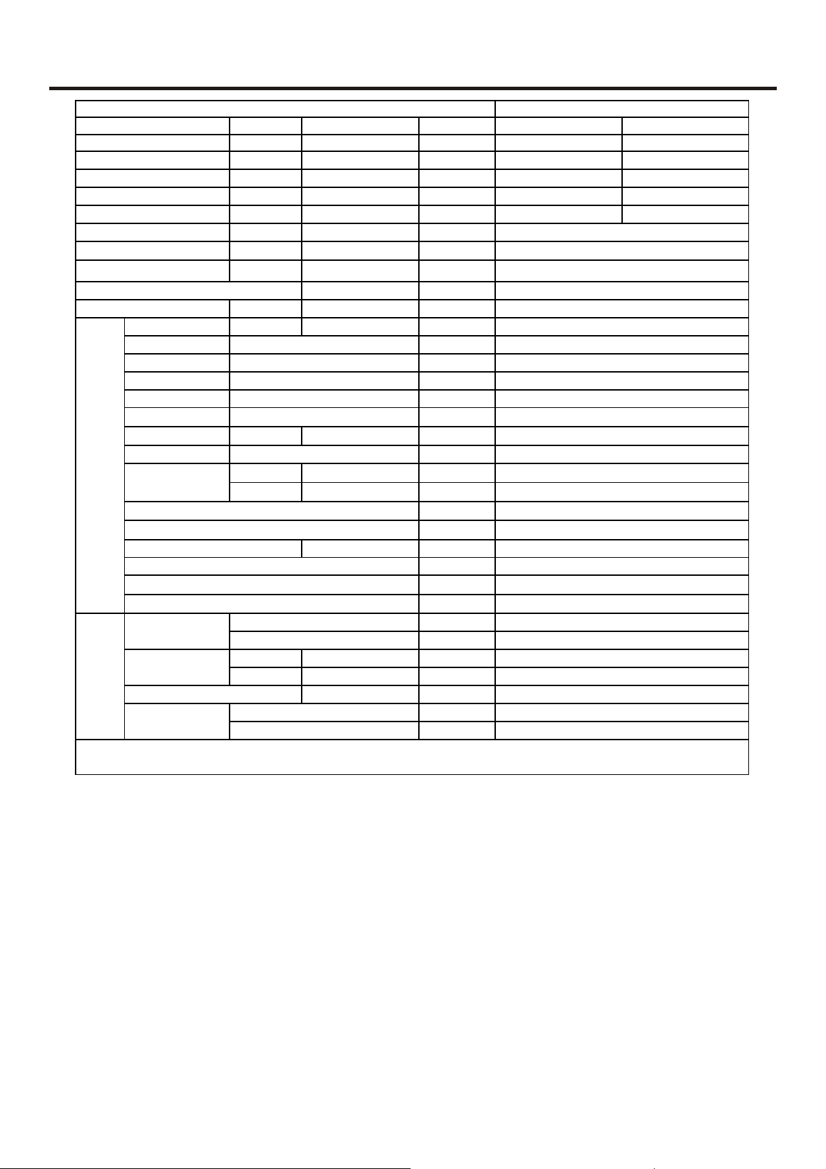
2 SPECIFICATIONS
item Model
Function
Capacity KW
Capacity BTU/h
Total power input W
Max. power input W
EER
or COP
Dehumidify capacity
Power cable
Power source
Running /Max.Running current A / A
Start current A
Unit model (color)
Fan type×number
speed (H-M-L) r/min
Fan motor output power W
Air-flow(H-M-L) m³/h
Heat exchanger
Type / Diameter
Total Area
Temp. scope
Dimension
indoor unit
Drainage pipe (material , I.D./O.D.) mm
Control type (Remote /wired)
Fresh air hole dimension mm
Electricity Heater
Noise level (H-M-L)
Weight (Net / Shipping)
Dimension
Panel
Weight (Net / Shipping)
External
Package
External
Package
(L×W×H)
(L×W×H)
(L×W×H)
(L×W×H)
W/W
10‐³×m³/h
N,V,Hz
mm
m²
℃
mm×mm×mm
mm×mm×mm
kW
dB(A)
kg / kg
mm×mm×mm
mm×mm×mm
kg / kg
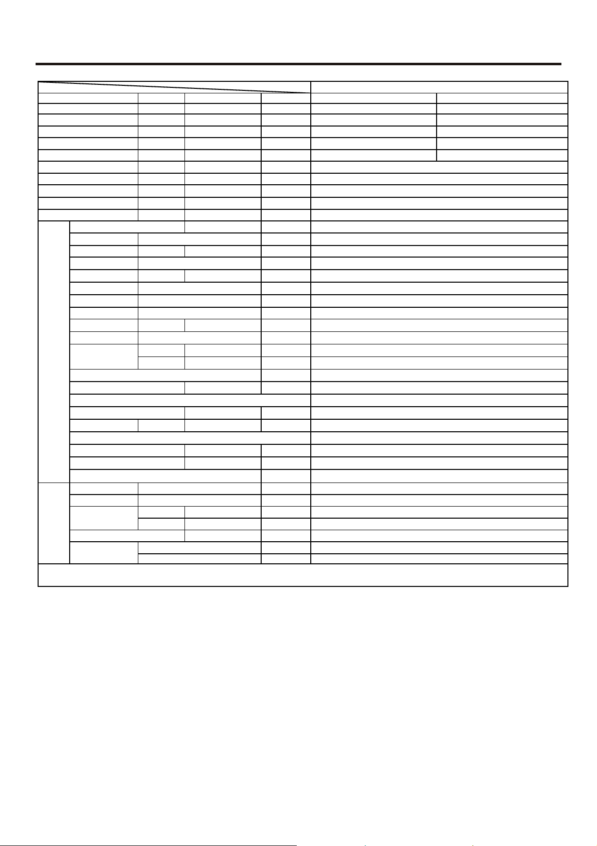
Unit model (color)
Compressor
Model / Manufacture
Type
Type × Number
Fan
Speed r/min
Fan motor output power kW
Air-flow(H-M-L) m³/h
Type / Diameter mm
Heat exchanger
Dimension
Outdoor unit
Drainage pipe (material , I.D./O.D.) mm
Total area m²
Temp. scope
External
Package
(L×W×H)
(L×W×H)
℃
mm×mm×mm
mm×mm×mm
Refrigerant control method mm/mm
Defrosting
Volume of Accumulator L
Noise level dB(A)
Type of Four way valve
material of reduce noise
crankcase heater power W
Weight (Net / Shipping)
Refrigerant
Pipe
Connecting Method
PIPING
Between I.D &O.
Type / Charge g
Recharge quantity g/m
Liquid mm
Gas mm
MAX.Drop
MAX.Piping length
kg / kg
m
m
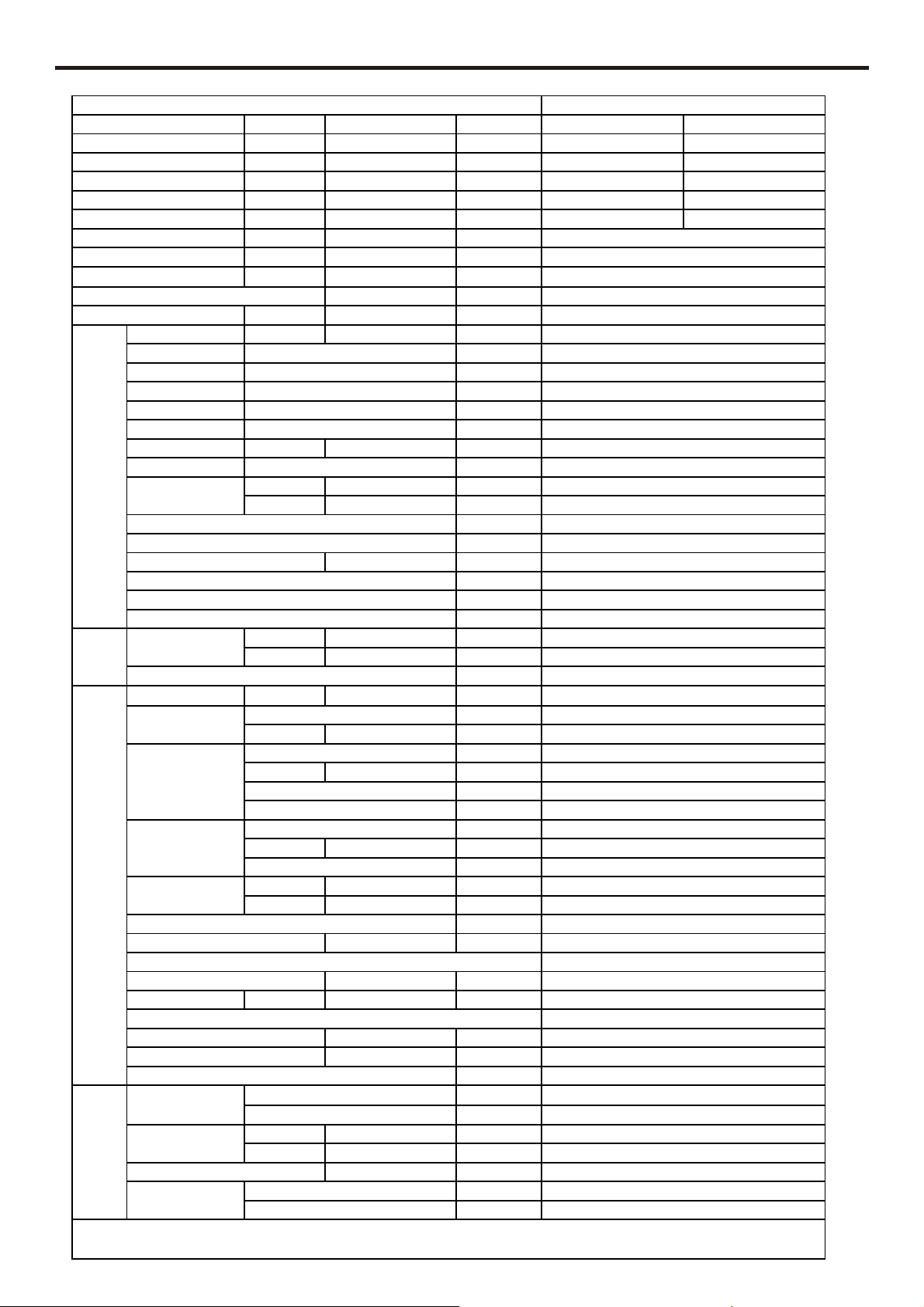
AU142AFBEA/AB142ACBEA
cooling heating
4.10 4.39
14000 15000
1550 1450
1800 1800
2.65 3.03
2.95
2X2.0+2X0.75
1PH 220V-230V 50HZ
cooling:7.8/8.5 heating:6.8/8.5
40
AB142ACBEA (grey)
centrifugal×1
900±30/850±30/750±30/610/540
20
1100/1000/900
9.52
653*200*65
5-10
700*570*276
775*715*361
PVC、26/32
remote
100
0
53.5/51.5/49.8
26/28
630*630*93
685*685*155
4.2/6.3
AU142AFBEA(WHITE)
PG260X2CS-4KT1 toshiba
rotary
Axial-flow
820±30
35
2300
TP2M/9.52
0.92
43-60
780x650x250
903x714x343
/
main: 1.7*400,auxiliary:2.0*140
auto
/
58/--/50
/
XPE
/
41/43
R407C 1600
50
6.35
12.7
flared
20
30

item Model
Function
Capacity KW
Capacity BTU/h
Total power input W
Max. power input W
or COP
EER
Dehumidify capacity
W/W
10‐³×m³/h
Power cable
Power source
N,V,Hz
Running /Max.Running current A / A
Start current A
Unit model (color)
Fan type×number
speed (H-M-L) r/min
Fan motor output power W
Air-flow(H-M-L) m³/h
Heat exchanger Type / Diameter mm
Total Area m²
Dimension
indoor unit
Temp. scope
External
Package
(L×W×H)
(L×W×H)
℃
mm×mm×mm
mm×mm×mm
Drainage pipe (material , I.D./O.D.) mm
Control type (Remote /wired)
Fresh air hole dimension mm
Electricity Heater /
Noise level (H-M-L)
Weight (Net / Shipping)
Dimension
Panel
Weight (Net / Shipping)
External
Package
(L×W×H)
(L×W×H)
kW
dB(A)
kg / kg
mm×mm×mm
mm×mm×mm
kg / kg
Unit model (color)
Compressor
Model / Manufacture
Type
Type × Number
Fan
Speed r/min
Fan motor output power kW
Air-flow(H-M-L) m³/h
Type / Diameter mm
Heat exchanger
Dimension
Outdoor unit
Drainage pipe (material , I.D./O.D.) mm
Total area m²
Temp. scope
External
Package
(L×W×H)
(L×W×H)
℃
mm×mm×mm
mm×mm×mm
Refrigerant control method mm/mm
Defrosting
Volume of Accumulator L
Noise level dB(A)
Type of Four way valve
material of reduce noise
crankcase heater power W
Weight (Net / Shipping)
Refrigerant
Pipe
PIPING
Connecting Method
Between I.D &O.
Type / Charge g
Recharge quantity g/m
Liquid mm
Gas mm
MAX.Drop 20
D
MAX.Piping length 30
kg / kg
m
m
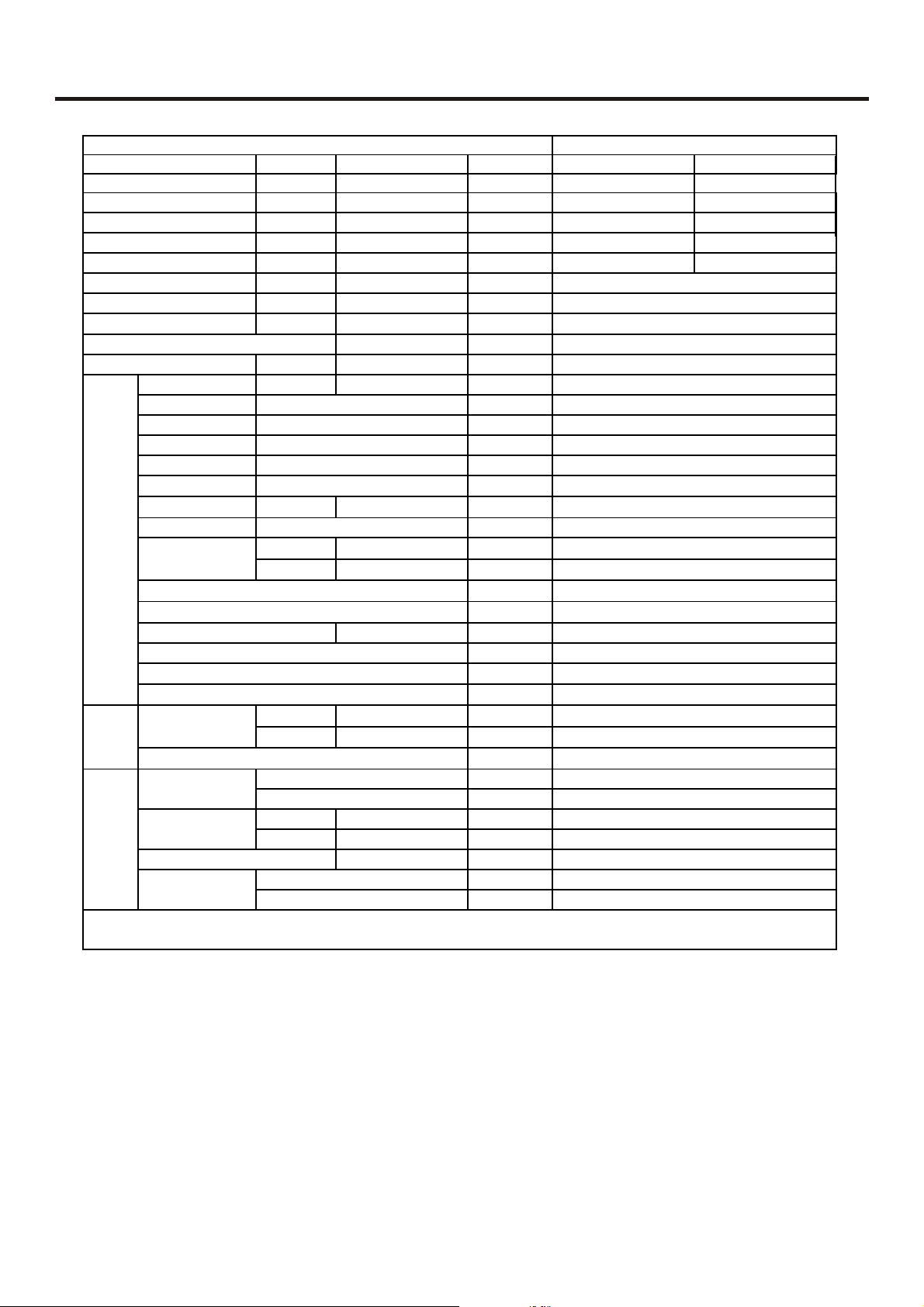
AU142AFBEA/AC142ACBEA
cooling heating
4.10 4.39
14000 15000
1550 1450
1800 1800
2.65 3.03
2.95
2X2.0+2X0.75
1PH 220V-230V 50HZ
cooling:7.8/8.5 heating:6.8/8.5
40
AC142ACBEA (white)
centrifugal×2
1350±30/1280±30/1210±30
20W
1100/1000/900
9.52
653*200*65
5-10
830*450*225
976*526*288
PVC、26/32
remote
/
53.5/51.5/49.8
20/22
/
/
/
AU142AFBEA(WHITE)
PG260X2CS-4KT1 toshiba
rotary
Axial-flow
820±30
35
2300
TP2M/9.52
0.92
43-60
780x650x250
903x714x343
/
main: 1.7*400,auxiliary:2.0*140
auto
/
58/--/50
/
XPE
/
41/43
R407C 1600
50
6.35
12.7
flared
Norminal condition: indoor temperature (cooling): 27 ℃DB/19℃WB, indoor temperature (heating): 20℃DB
Outdoor temperature(cooling): 35℃DB/24℃WB, outdoor temperature(heating): 7 ℃DB/6℃WB
item Model
Function
Capacity KW
Capacity BTU/h
Total power input W
Max. power input W
EER
Dehumidify capacity
Power cable
Power source
Running /Max.Running current A / A
Start current A
AU142AFBEA/AD142AMBEA
cooling heating
4.10 4.39
14000 15000
1550 1450
1800 1800
or COP
W/W
2.65 3.03
10‐³×m³/h
N,V,Hz
1PH 220V-230V 50HZ
cooling:7.8/8.5 heating:6.8/8.5
Unit model (color)
AD142AMBEA (white)
Fan type×number
speed (H-M-L) r/min
1290±30/1220±30/940±30/710±40
Fan motor output power W
Air-flow(H-M-L) m³/h
Heat exchanger Type / Diameter mm
Total Area m²
Temp. scope
Dimension
indoor unit
External
Package
(L×W×H)
(L×W×H)
℃
mm×mm×mm
mm×mm×mm
Drainage pipe (material , I.D./O.D.) mm
Control type (Remote /wired)
Fresh air hole dimension mm
Electricity Heater /
Noise level (H-M-L)
Weight (Net / Shipping)
Dimension
Panel
Weight (Net / Shipping)
External
Package
(L×W×H)
(L×W×H)
Unit model (color)
Compressor
Model / Manufacture
Type
kW
dB(A)
kg / kg
mm×mm×mm
mm×mm×mm
kg / kg
AU142AFBEA(WHITE)
PG260X2CS-4KT1 toshiba
Type × Number
Fan
Speed r/min
Fan motor output power kW
Air-flow(H-M-L) m³/h
Type / Diameter mm
Heat exchanger
Dimension
Outdoor unit
Drainage pipe (material , I.D./O.D.) mm
Refrigerant control method mm/mm
Total area m²
Temp. scope
External
Package
(L×W×H)
(L×W×H)
℃
mm×mm×mm
mm×mm×mm
main: 1.7*400,auxiliary:2.0*140
Defrosting
Volume of Accumulator L
Noise level dB(A)
Type of Four way valve
material of reduce noise
crankcase heater power W
Weight (Net / Shipping)
Refrigerant
Pipe
PIPING
Connecting Method
Between I.D &O.
Type / Charge g
Recharge quantity g/m
Liquid mm
Gas mm
MAX.Drop 20
D
MAX.Piping length 30
kg / kg
m
m
2.95
2X2.0+2X0.75
40
centrifugal×2
20W
950/850/770
9.52
653*200*65
5-10
830*450*225
980*543*305
PVC、18/21
remote
/
40/38/36
25/28
/
/
/
rotary
Axial-flow
820±30
35
2300
TP2M/9.52
0.92
43-60
780x650x250
903x714x343
/
auto
/
58/--/50
/
XPE
/
41/43
R407C 1600
50
6.35
12.7
flared
Norminal condition: indoor temperature (cooling): 27 ℃DB/19℃WB, indoor temperature (heating): 20℃DB
Outdoor temperature(cooling): 35℃DB/24℃WB, outdoor temperature(heating): 7 ℃DB/6℃WB
item Model
Function
Capacity KW
Capacity BTU/h
Total power input W
Max. power input W
EER or COP
Dehumidify capacity
Power cable
Power source
Running /Max.Running current A / A
Start current A
Unit model (color)
Fan type×number
speed (H-M-L) r/min
Fan motor output power W
Air-flow(H-M-L) m³/h
Heat exchanger Type / Diameter mm
Total Area m²
Temp. scope
Dimension
indoor unit
Drainage pipe (material , I.D./O.D.) mm
Control type (Remote /wired)
Fresh air hole dimension mm
Electricity Heater
Noise level (H-M-L)
Weight (Net / Shipping)
Dimension
Panel
Weight (Net / Shipping)
Refrigerant
Pipe
PIPING
Connecting Method
Between I.D &O.D
Norminal condition: indoor temperature (cooling): 27 ℃DB/19℃WB, indoor temperature (heating): 20℃DB
Outdoor temperature(cooling): 35℃DB/24℃WB, outdoor temperature(heating): 7 ℃DB/6℃WB
External
Package
External
Package
Type / Charge g
Recharge quantity g/m
Liquid mm
Gas mm
MAX.Drop
MAX.Piping length
(L×W×H)
(L×W×H)
(L×W×H)
(L×W×H)
WW
10‐³×m³/h
N,V,Hz
℃
mm×mm×mm
mm×mm×mm
kW
dB(A)
kg / kg
mm×mm×mm
mm×mm×mm
kg / kg
m
m
cooling heating
18000 20000
cooling: 10/12 heating: 9.5/14
AB182ACBEA
5.27 5.86
2000 1900
2400 2800
2.64 3.08
1.2
4X0.75
1PH 220V-230V 50HZ
50
AB182ACBEA(WHITE)
CENTRIFUGAL*1
500±30/450±40/380±50
0.04
1050/945/790
TP2M/7
0.199
2-7
750×750×280
900×900×460
PVC 26/32
remote
/
/
43/42/40
29/39
750x750x80
800x800x180
3.5/5.8
R407C 1950
30
6.35
15.88
flared
20
30
item Model
Function
Capacity KW
Capacity BTU/h
Total power input W
Max. power input W
EER or COP
Dehumidify capacity
Power cable
Power source
Running /Max.Running current A / A
Start current A
Unit model (color)
Fan type×number
speed (H-M-L) r/min
Fan motor output power W
Air-flow(H-M-L) m³/h
Heat exchanger Type / Diameter mm
Total Area m²
Temp. scope
Dimension
indoor unit
Drainage pipe (material , I.D./O.D.) mm
Control type (Remote /wired)
Fresh air hole dimension mm
Electricity Heater
Noise level (H-M-L)
Weight (Net / Shipping)
Refrigerant
Pipe
PIPING
Connecting Method
Between I.D &O.D
Norminal condition: indoor temperature (cooling): 27 ℃DB/19℃WB, indoor temperature (heating): 20℃DB
Outdoor temperature(cooling): 35℃DB/24℃WB, outdoor temperature(heating): 7 ℃DB/6℃WB
External
Package
Type / Charge g
Recharge quantity g/m
Liquid mm
Gas mm
MAX.Drop
MAX.Piping length
(L×W×H)
(L×W×H)
W/W
10‐³×m³/h
N,V,Hz
℃
mm×mm×mm
mm×mm×mm
kW
dB(A)
kg / kg
m
m
cooling heating
18000 20000
cooling: 10/12 heating: 9.5/14
AC182ACBEA
5.27 5.86
2000 1900
2400 2800
2.64 3.08
2.1
4X0.75
1PH 220V-230V 50HZ
50
AC182ACBEA(WHITE)
CENTRIFUGALX2
1070+30/1000+40/940+50
0.04
900/840/790
TP2M/9.52
0.199
2-7
1990×655×199
1150×750×300
PVC 18/20
remote
/
/
48/44/38
30/39
R407C 1950
30
6.35
15.88
flared
20
30

item Model
Function
Capacity KW
Capacity BTU/h
Total power input W
Max. power input W
EER or COP
Dehumidify capacity
Power cable
Power source
Running /Max.Running current A / A
Start current A
Unit model (color)
Fan type×number
speed (H-M-L) r/min
Fan motor output power W
Air-flow(H-M-L) m³/h
Heat exchanger Type / Diameter mm
Total Area m²
Temp. scope
Dimension
indoor unit
Drainage pipe (material , I.D./O.D.) mm
Control type (Remote /wired)
Fresh air hole dimension mm
Electricity Heater
Noise level (H-M-L)
Weight (Net / Shipping)
Refrigerant
Pipe
PIPING
Connecting Method
Between I.D &O.D
Norminal condition: indoor temperature (cooling): 27 ℃DB/19℃WB, indoor temperature (heating): 20℃DB
Outdoor temperature(cooling): 35℃DB/24℃WB, outdoor temperature(heating): 7 ℃DB/6℃WB
External
Package
Type / Charge g
Recharge quantity g/m
Liquid mm
Gas mm
MAX.Drop
MAX.Piping length
(L×W×H)
(L×W×H)
WW
10‐³×m³/h
N,V,Hz
cooling: 10/12 heating: 9.5/14
℃
mm×mm×mm
mm×mm×mm
kW
dB(A)
kg / kg
m
m
AD182AMBEA
cooling heating
5.27 5.86
18000 20000
2000 1900
2400 2800
2.64 3.08
1.2
4X0.75
1PH 220V-230V 50HZ
50
AD182AMBEA(WHITE)
CENTRIFUGALx2
780+30/710+30/630+50
0.13
850/770/680
TP2M/9.52
0.199
2-7
990×650×300
1137×800×320
PVC 26/32
wired+remote
/
/
33/31/28
38/55
R407C 1950
30
6.35
15.88
flared
20
30
g
g
y
ping
item Model
Function
Capacit
Capacity BTU/h
Total power input
Max. power input
EER or COP
Dehumidifying capacity
Power cable
Power source
Running /Max.Running
Start Current A
Unit model (color)
Compressor Model / Manufacture
Type
Fan Type × Number
Speed r/min
Fan motor output power kW
Air-flow(H-M-L) m³/h
Heat exchanger Type / Diameter mm
Total area m²
Temp. scope
Dimension
Outdoor unit
Drainage pipe (material , I.D./O.D.) mm
Refrigerant control method mm/mm
Defrosting
Volume of Accumulator L
Noise level dB(A)
Type of Four way valve
material of reduce noise
crankcase heater power W
Weight (Net / Shipping)
Refrigerant Type / Charge g
Pipe
PIPING
Connecting Method
Between I.D &O.
Norminal condition: indoor temperature (cooling): 27℃DB/19℃WB, indoor temperature (heating): 20℃DB
Outdoor temperature(cooling): 35℃DB/24℃WB, outdoor temperature(heating): 7℃DB/6℃WB
External
Package
Recharge quantity g/m
Liquid mm
Gas mm
MAX.Drop 20
MAX.Pi
(L×W×H)
(L×W×H)
length 30
KW
W
W
W/W
10‐³×m³/h
N,V,Hz
A / A
℃
mm×mm×mm
mm×mm×mm
kg / kg
m
m
Coolin
5.27 5.86
18000 20000
2000 1900
2400 2800
2.64 3.08
cooling: 10/12 heating: 9.5/14
PG330X2CS-4KU1 Toshiba
Main capillary2.0x450;Sub-capillary2.0x200
AU182AFBEA
1PH 220V-230V 50HZ
AU182AFBEA(WHITE)
810x288x680
960x406x760
R407C 1950
Heatin
2.1
4X0.75
50
Rotary
Axial-flow
820±30
35
2000
TP2M/9.52
0.72
43-60
/
Auto
/
52/--/46
/
XPE
/
59/66
30
6.35
15.88
Flare

3 MECHANICAL DATA
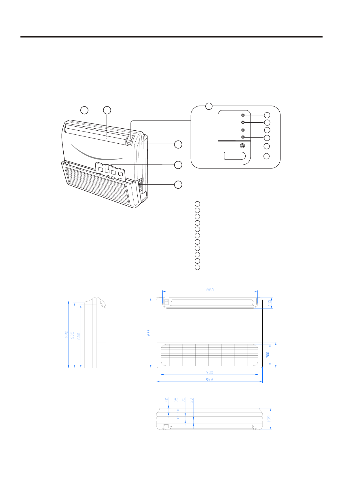
3.1 Drawings / Dimensions
3.1.1 Cassette Indoor unit
Swing louver
(Air flow direction can be adjusted by using
the SWING button on the remote controller)
Electrical Components Case
Air Inlet Grille
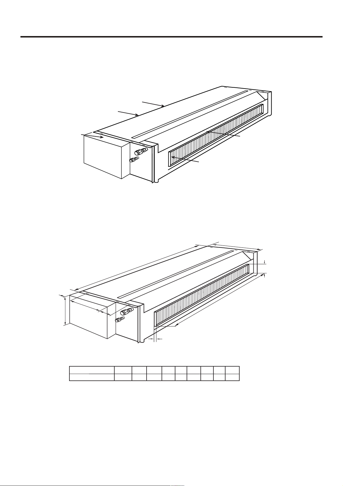
3.1.2 outdoor unit
Air Filter (Inside of the Inlet Grille)
Air inlet
Compressor(inside of unit)
Air outlet
18 series

Dimension
(Ceiling opening hole)
e
l
e
c
t
r
i
c
a
l
b
o
x
)
e
l
o
h
g
n
i
n
e
p
o
g
)
n
i
置
l
i
位
e
C
挂
(
悬
(
400
190
65
75
N
I
M
110
150
.
N
I
M
M
I
N
.
.
M
I
N
.
Needed minimum position
480
265
30
170
200
220
680
100 100
810
580
288
Convertible type
Fig.1
Dimension
Fig.2
1
POWER
OPER
TIMER
COMP
EMER
4
5
6
7
2
3
1110
3
9
8
Fig.1 Indoor Unit
1 Operating Control Panel (Fig.2)
2 Emergency switch
3 Remote Control Signal Receiver
4 Power Indicator Lamp (Red)
5 OPERATION Indicator Lamp (Green)
6 TIMER Indicator Lamp (Yellow)
7 Compressor Run Lamp (Green)
8 Intake Grill (Fig.3)
9 Air Filter
10
UP/DOWN Air Direction Flaps
11
RIGHT/LEFT Air Direction Louvers
(behind UP/DOWN Air Direction Flaps)
5
5
6
0
0
2
240
9
ceiling concealed type Indoor unit
fan inside
motor inside
electric control box
C
B
air duct
evaporator
A
@
G
D
?
E
9JLM?HH?MGKJ BGICJLGKJ4 +=JGM4 II,
<>;8
57.1/5:685
?@ABCDEFG
2-- 30- 12- //2 3- //2 ./0 // .--
F
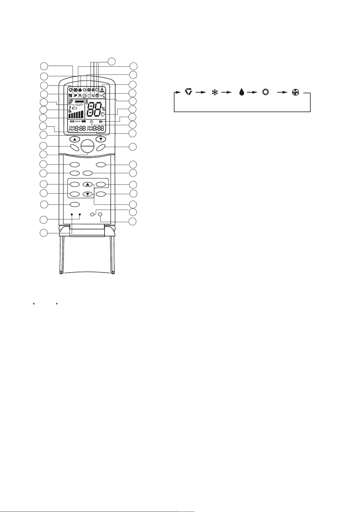
7.Remote controller functions
Remote controller
29
30
31
32
33
34
35
36
1
2
3
4
5
6
7
8
9
SWING
RESET
M D
MODE
HEALTH
CLOCK
TIMER
FILTER
CODE
A
U
T
O
OFF
TEMP
ON
OFF
FRESH
LIGHT
SLEEP
HIGH/SO
LOCK
SET
4.Operation MODE
28
B
A
FAN
27
26
25
24
23
22
21
20
19
18
17
16
15
14
13
12
11
Used to select operation mode.
Every time you press MODE button, operation mode
changes according to following sequence:
AUTO
COOL
DRY
HEAT
FAN
5.HEALTH Button
Used to set health mode, if the unit has the negative ion function
and oxygen bar function.
6.CLOCK Button
Used to set correct time.
7.CLOCK Button
Used to select TIMER ON, TIMER OFF.
(Note: if time of TIMER ON is the same as TIMER
OFF ,TIMER ON/OFF cannot be set)
8. FILTER Button
Used to set up/down function of filter.
9. CODE Button
Used to select code A or B, for this unit, the code is A.
10
1.TEMP Setting Button
(Used to set temperature. Setting ranges:
16 C to 30 C)
In Up/Down function, for controlling up and
down filter.
2.SWING Button
If you press this button once, auto swing will
be activated.
If you press this button again, the louver will
fix in the present position.
3.Power ON/OFF Button
Used for unit start and stop
After power on, the LCD of remote controller
will display the previous operation state (except
for TIMER,SLEEP and SWING state).
10.RESET Button
Press this button by using a sharp article to resume
the correct operation of the remote controller in case
of need, i.e. for example in case of malfunctions due
to electromagnetic noise.
11.LOCK Button
Used to lock operation button and LCD display
contents: by pressing this button, other buttons comes
out of function and lock state display appears; if you press
it again, lock state will be no more active and lock state
display will disappear.
12.LIGHT Button
Used to light the control panel (only for cabinet unit)
13.Up and down Button
Used to set TIMER and CLOCK up or down.
14.HIGH/SO Button
Used to select HIGH or SOFT operation.
15.SET Button
Used to confirm TIMER and CLOCK settings.
16.FRESH Button
Used to set fresh mode, the unit will draw in fresh air.
17.SLEEP Button
(The clock must be corrected before setting sleep
function)
Used to set sleep mode.
NOTE: 1.Cooling only air conditioner does not have the displays and functions related to heating.
2.HIGH/SO button
This button is activated in Cooling/Heating mode, the fan speed is in AUTO mode after pressing it and "high
functon" will be cancelled automatically after 15 minutes running.
18.FAN Button
Used to select fan speed:LOW,MID,HIGH,AUTO.
19.TIMER OFF Display
20.CLOCK Display
21.FILTER Display
22.TEMPERATURE Display
23.AUTO SWING Display
24.HIGH/SO Display
25.SIGNAL SENDING Display
26.FRESH AIR Display
27.ELECTRICAL HEATING Display
28.Some other buttons
All these functions are not available now.
29.HEALTH Display
Displays when healthy run function is set.
30.DEHUMIDIFICATION Display
31.Operation MODE Display
AUTO RUN
COOL RUN
DRY RUN
HEAT RUN
FAN RUN
32.SLEEP State Display
33.BATTERY Energy Display
Notify the user when it is time to change
the batteries.
34.LOCK State Display
35.FAN SPEED Display
LO
MID
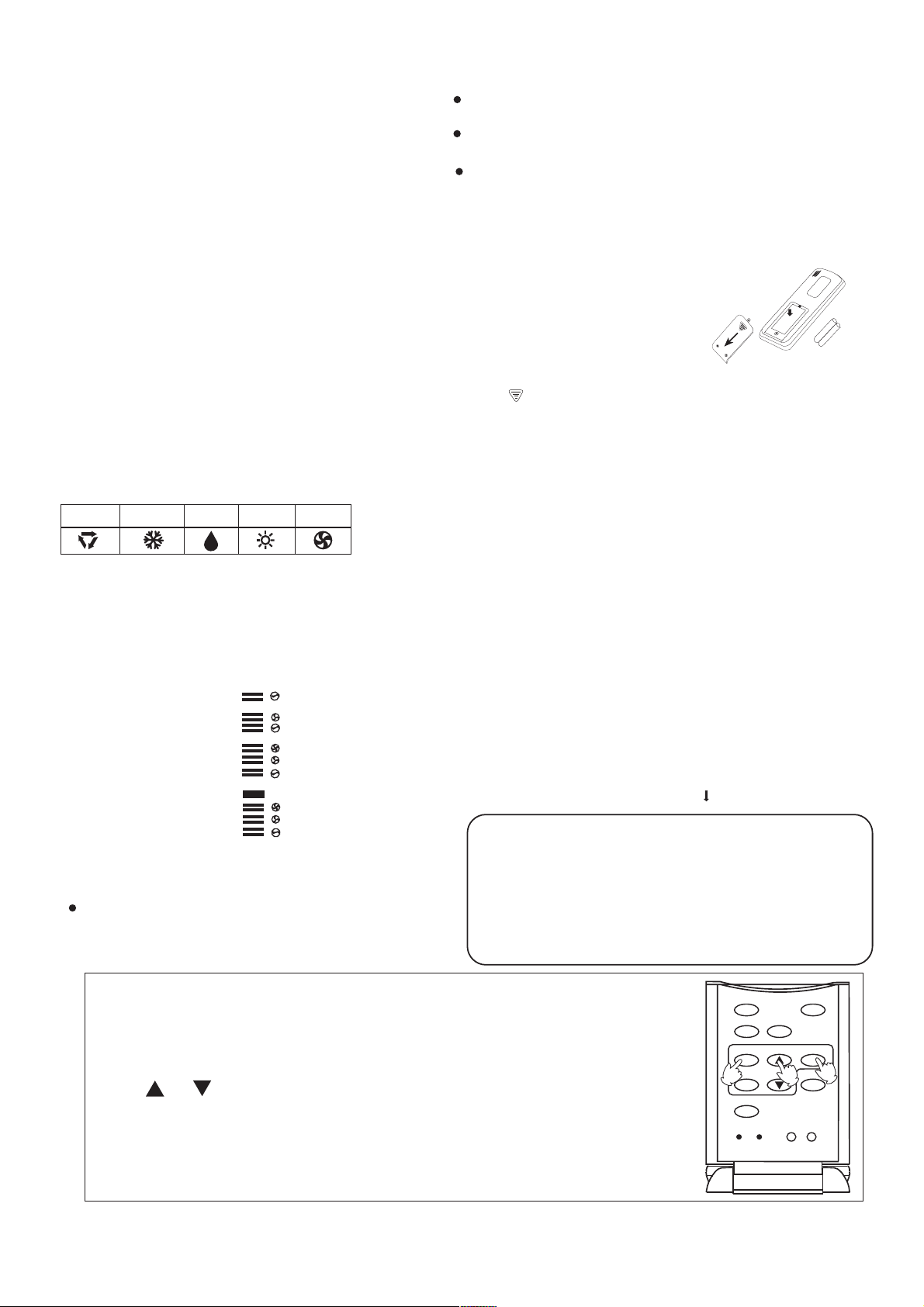
The distance between the remote controller and the receiver
should be max 7m and there should be no obstacle between them.
Do not throw the remote controller; prevent it from being
damaged.
When operating the remote controller in an area where
electronically controlled lights are installed or wireless handsets
are used, please move closer to the indoor unit as the function
of the remote controller might be affected by signals emitted
by the above mentioned equipments.
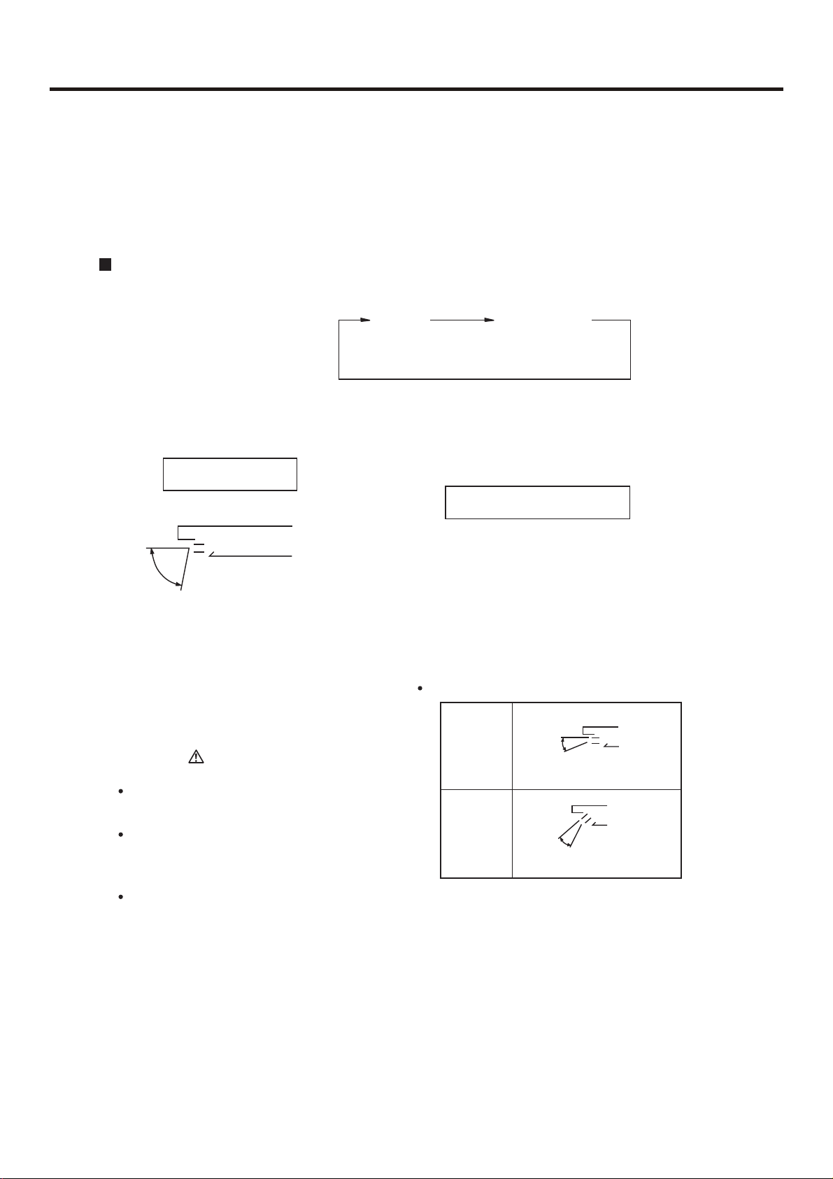
Battery loading
Battery loading
Batteries are fitted as follows:
Remove the battery compartment lid
Slightly press and disengage the battery compartment lid marked
with ì
section and then remove the battery compartment lid by pressing
in the direction of the arrow as shown in the figure above.
î and then hold the remote controller by the upper
Loading the battery
Ensure that batteries are correctly placed in the compartment
as required for positive and negative terminals.
Replacing the battery compartment lid
The battery compartment lid is reinstalled in the reverse
sequence.
Display review
Press the button to see if batteries are properly fitted. If
no display appears, refit the batteries.
Confirmation indicator
If no indication is displayed after press ON/OFF button,
reload the batteries.
Caution:
* *
* *
HI
AUTO
AUTO
If the remote controller does not operate as designed after
fitting new batteries of the same
type, press the Reset button (marked ) with a pointed article.
Note:
36.TIMER ON Display
Remote Controller' Operation
When in use, direct signal transmission
head to the receiver placed on the indoor
unit
It is recommended that the batteries be removed from the
compartment if the remote controller is not used for an extended
period.
The remote controller is programmed for automatic test of
operation mode after the batteries are replaced. When the test
is conducted, all icons will appear on the screen and then
disappear if the batteries are properly fitted.
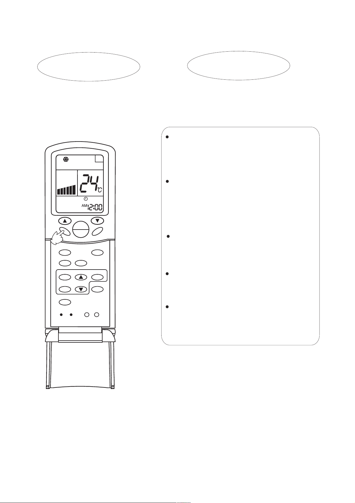
Clock Set
When unit is started for the first time and after replacing batteries in remote
controller, clock should be adjusted as follows:
1.Press CLOCK button, clock indication of " AM " or " PM " flashes.
2.Press or to set correct time. Each press will increase or decrease
1 min. If the button is kept pressed, time will increase or decrease quickly.
3.After time setting is confirmed, press "SET" : AM or PM stop flashing,
while clock starts working.
Note:AM means morning and PM means afternoon.
1
RESET
HEALTH
CLOCK
TIMER
FILTER
CODE
FRESH
2
LIGHT
SLEEPMODE
SET
HIGH/SO
LOCK
3
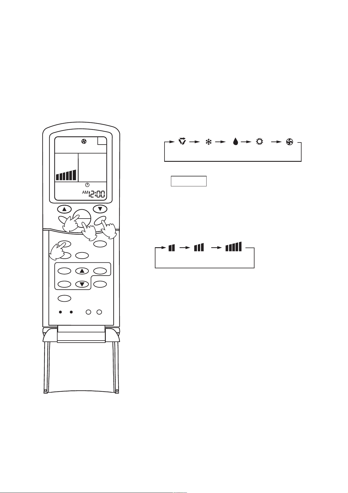
Fan Operation
1.Unit start
Press ON/OFF button to start your air conditioner.
Previous operation status appears on LCD (except for
TIMER, SLEEP, and SWING setting).
2.Select operating mode
Press MODE button. At each press, operation mode
changes as follows:
A
SWING
MODE
HEALTH
2
CLOCK
TIMER
FILTER
RESET
4
CODE
A
U
T
O
TEMP
ON
OFF
FRESH
1
LIGHT
FAN
SLEEP
SET
HIGH/SO
LOCK
AUTO
FANHEATCOOL DRY
Then select FAN
3. Adjust fan speed
Press FAN button. At each press, fan speed changes as
3
follows:
LOW
MID
HIGH
Air conditioner will run at the selected fan speed.
When in AUTO mode, unit will adjust fan speed
according to room temperature automatically.
4. Unit stop
Press ON/OFF button to stop unit.
About FAN mode
When the air conditioner runs in F AN mode,
it is not possible to select AUTO FAN or to
set temperature.
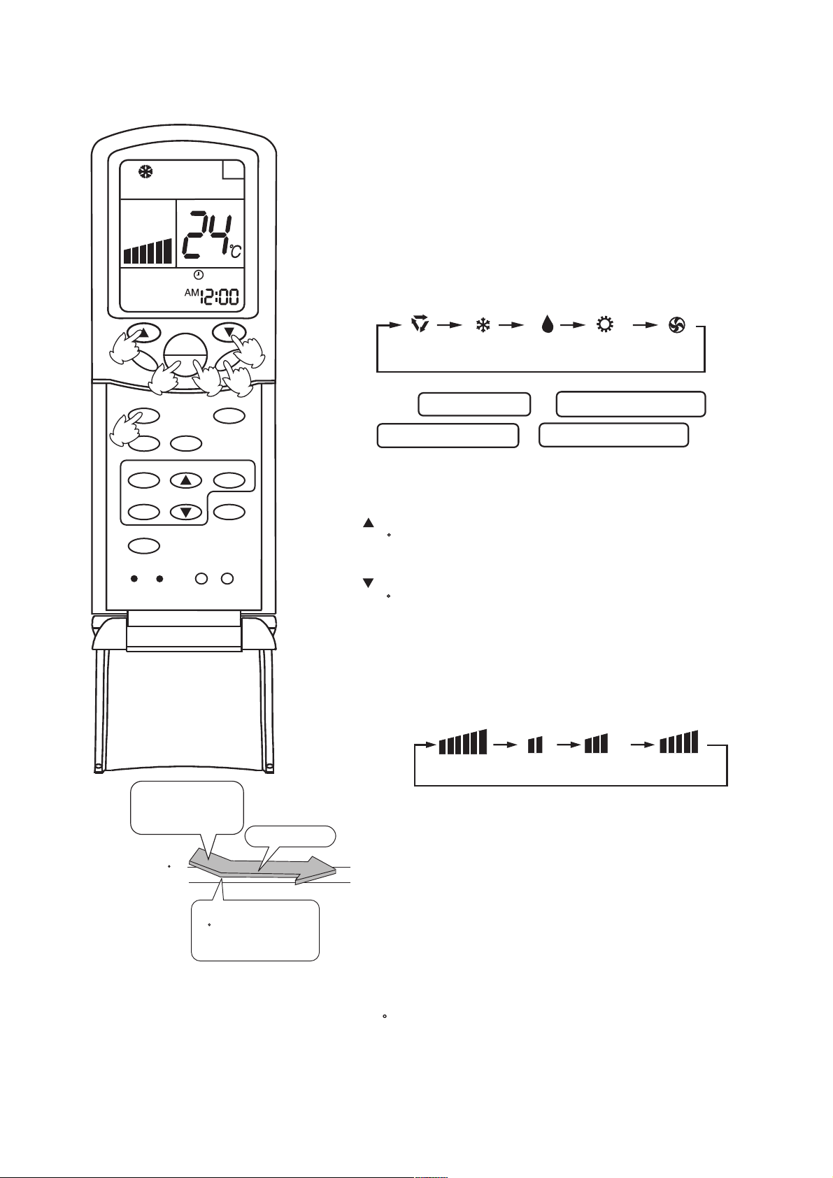
AUTO, COOL , HEAT and DRY Operation
3
SWING
MODE
HEALTH
2
CLOCK
TIMER
FILTER
RESET
5
CODE
A
U
T
O
TEMP
ON
OFF
FRESH
LIGHT
1
SLEEP
HIGH/SO
SET
LOCK
A
FAN
4
1. Unit start
Press ON/OFF button,unit starts.
Previous operation status appears on LCD (except for TIMER,
SLEEP and SWING setting)
2.Select operation mode
Press MODE button. At each press, operation mode changes
as follows:
3
AUTO
FANHEATCOOL DRY
Then select AUTO run or select COOL operation or
select DRY operation or select HEAT operation
3.T emperature setting
Press TEMP button.
Every time the button is pressed, temp. setting increases
1 C; if the button is kept pressed, temp. setting will increase
quickly .
Every time the button is pressed, temp. setting decreases
1 C, if the button is kept pressed, temp. setting will decrease
quickly .
Set proper temperature
4.Adjust FAN button
Press F AN button. At each press, fan speed changes as follows:
A
U
T
O
COOL operation starts
when room temp.is
higher than temp.
setting.
Temp. setting +2 C
Temp.setting
Ultra-low air flow
On reaching temp.setting
+2 C, unit will run in mild
DRY mode.
AUTO
Air conditioner will run at the selected fan speed.
5. Unit stop
Press ON/OFF button,unit stops.
LOW
In ATUO mode, the temperature setting is not displayed on LCD. In this mode, during running air conditioner
will select COOL, HEAT or FAN mode automatically according to the room temperature.
In DRY mode, when room temperature becomes 2 C higher than temperature setting, unit will run intermittently
at LOW speed regardless of FAN setting. When room temperature is lower than temperature setting, unit will
only run F AN operation.
In HEAT mode,warm air will blow out after a short period of time due to cold-draft prevention function.
MID HIGH
Adjusting air flow direction
AUTO SWING
Press SWING button.
Up and down airflow varies upwards
and downwards. Left and right airflow
varies left and right sides.
A
A
U
T
O
TEMP
ON
SWING
OFF
MODE
FAN
SLEEP
AUTO SWING
When the automatic swing louver moves to the proper
angle, press SWING button can fix the airflow direction.
Always use SWING button on the remote
controller to adjust flaps. Adjusting them by hand
may result in air conditioner's abnormally running.
In COOL or DRY mode, do not leave the louver in
downward position for a long time, as the water
vapor close to the grille may condense and water
may drop from the air conditioner.
Please carefully set temperature when children,
old or infirm people ues the air conditioner.
FRESH
HEALTH
LIGHT
SET
HIGH/SO
LOCK
In case of great humidity, If the vertical flaps
are completely turned towards left or right, the
louver will drop water.
Never adjust the louver directly by hand, as this
CLOCK
TIMER
FILTER
RESET
CODE
could make it work abnormally .If the louver work
abnormally , stop unit, restart and adjust the louver
by remote controller.
After unit stops:
Displays on the LCD disappear.
All indicators on the indoor unit go out.
Swing louver automatically close the air outlet.
Hints:
As in COOL mode air flows downwards, adjusting airflow horizontally will be much more helpful
for a better air circulation
As in HEAT mode air flows upwards, adjusting airflow downward will be much more helpful for
a better air circulation.
Be careful not to catch a cold when cold air blows downward directly.

Sleep Function
Before going to bed you can press down the SLEEP button and the air conditioner will run so as to make
you sleep more comfortably.
Before using this function, the clock must be set.
Use of SLEEP function
After the unit's start, set running mode and then press SLEEP button once to make the air conditioner
have the previous-set sleep time (first power-on is "1h"). The sleep symbol will appear. Press time button
/ : you can choose the time in 1~8 hours. Each time the button is pressed, the time increases/decreases 1
hour: "xh" and "OFF" indications appear on the display.
Operation Mode
1.In COOL, DRY mode
One hour after sleeping operation start, the temperature
is 1 C higher than the setting one. After another hour,
temperature rises 1 C: sleep run continuously for another
6 hours and then stops. The actual temperature is higher
than the setting one which is to prevent from being too
cold to your sleep.
2.In HEAT mode
One hour after sleeping operation start, the temperature
is 2 C lower than the setting one. After another hour,
temperature decreases by 2 C more. Temperature will
automatically rise by 1 C after another 3 hours'
continuous operation. The actual temperature is lower
than the setting one which is to prevent from being too
hot to your sleep.
3.In AUTO mode.
The air conditioner will run in corresponding sleep
operation according to the automatically selected
operation mode.
SLEEP RUN BEGINS
1 hrs
SETTING T
In COOL,DRY mode
SETTING T
1 hrs
1 hrs
SLEEP RUN BEGINS
In HEAT mode
SLEEP RUN STOPS
about 6 hrs
increase 1 C
increase 1 C
decrease 2 C
decrease 2 C
about 6 hrs
3 hrs
SLEEP RUN STOPS
SHUT DOWN
SHUT DOWN
increase 1 C
Notes:
After setting SLEEP function, it is not possible to set clock.
If set-sleep time does not reach 8 hours, unit will automatically stop operation
after set time is reached.
Set " TIMER ON " or " TIMER OFF "In COOL,DRY mode function first,
then set SLEEP. After set SLEEP function, the TIMER function cannot be
set.
SWING
RESET
MODE
HEALTH
CLOCK
TIMER
FILTER
A
A
U
T
O
OFF
TEMP
ON
OFF
FAN
SLEEP
FRESH
SET
HIGH/SO
LOCK
LIGHT
CODE
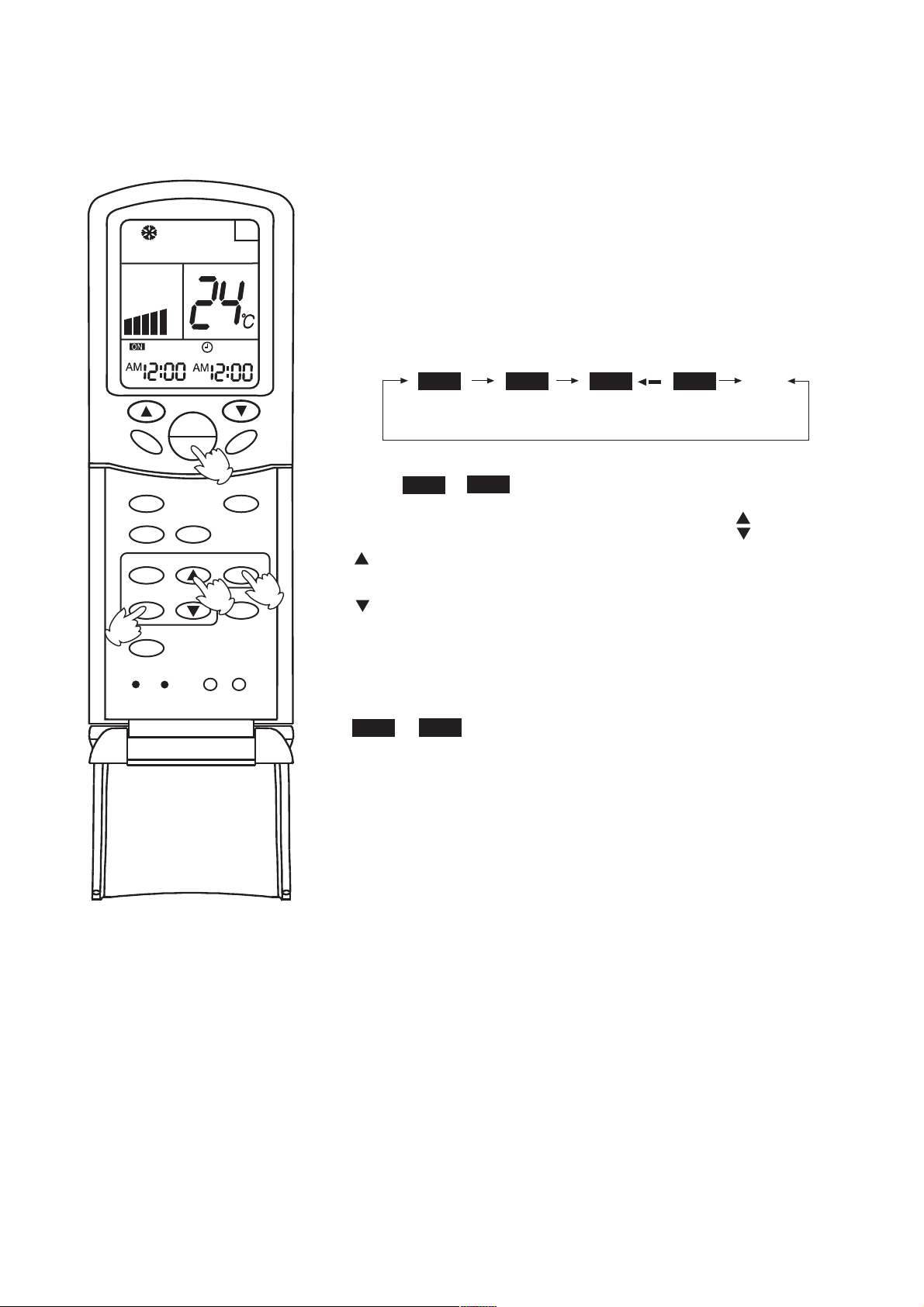
Timer ON/OFF Function
Set clock correctly before starting TIMER operation
1.Unit start
A
After unit start, select your desired operation mode (operation
mode will be displayed on LCD)
2.TIMER mode selection
Press TIMER button on the remote controller to change TIMER
mode. Every time the button is pressed, display of TIMER mode
changes as follows:
SWING
MODE
HEALTH
CLOCK
TIMER
2
FILTER
RESET
CODE
TEMP
ON
OFF
FRESH
LIGHT
1
3
FAN
SLEEP
SET
HIGH/SO
LOCK
ON OFF ON OFF
AM
12:00
TIMER ON
PM
12:00
TIMER OFF
AM
12:00
TIMER ON-OFF
PM
12:00
blank
Then select TIMER mode as needed (TIMER ON or TIMER OFF).
Now or will flash.
ON
OFF
3.TIMER setting (press time adjust buttons )
Every time the button is pressed, time increases 10 minuts.
If the button is kept pressed, time changes quickly.
4
Every time the button is pressed, time decreases 10 minuts.
If the button is kept pressed, time changes quickly.
It can be adjusted within 24 hours at will.
4.Confirm setting
After setting correct time, press SET button to confirm time. Now
or stop flashing.
ON
OFF
Time displayed: unit starts or stops at X hour X min (TIMER ON
or TIMER OFF)
5.Cancel TIMER mode
Just press TIMER button several times until TIMER mode disappears.
Hints:
After replacing batteries or if a power failure occurs, TIMER setting
must be reset.
Remote controller has memory function. When you use TIMER
mode next time, just press SET button after mode selection if timer
setting is the same as the previous one.
Note:
After setting TIMER function, the remote controller displays TIMER time. If you want to see clock time,
just press CLOCK button once: clock time will be displayed (if you press the button again continuously ,you
can adjust clock). 5 seconds later, the display will show TIMER time again.

Timer ON-OFF Function
Set clock correctly before starting TIMER operation
1.Unit start
After unit start, select your desired operation mode (operation
mode will be displayed on LCD)
SWING
2
MODE
HEALTH
CLOCK
TIMER
FILTER
4
RESET
5
CODE
OFF
TEMP
ON
OFF
FRESH
LIGHT
1
3
A
FAN
SLEEP
SET
HIGH/SO
LOCK
2.TIMER mode selection
Press TIMER button on the remote controller to change TIMER
mode. Every time the button is pressed, display of TIMER mode
changes as follows:
ON
AM
12:00
TIMER ON
OFF
PM
12:00
TIMER OFF
AM
ON
12:00
Then select TIMER ON-OFF mode.
OFF
PM
12:00
TIMER ON-OFF
ON
will flash.
blank
3.Time setting for TIMER ON
Press time button
Every time the button is pressed, time increases 10 minuts.
If the button is kept pressed, time will changes quickly.
Every time the button is pressed, time decreases 10 minuts.
6
If the button is kept pressed ,time will changes quickly.
It can be adjusted within 24 hours at will.
AM refers to morning and PM refers to afternoon.
4.Timer confirming for TIMER ON
After setting correct time, press TIMER button to confirm time. Now
stops to flash, while
ON
starts flashing.
OFF
Time displayed : unit starts at X hour X min.
5.Timer setting for TIMER OFF
Press time buttons and follow the same procedures in " Time setting
for TIMER ON"
6.Time confirming for TIMER OFF
After time setting, press SET button to confirm time.
Time displayed: unit starts at X hour X min.
stops to flash.
OFF
7.Canel TIMER mode
Just press TIMER button several times until TIMER mode disappears.
According to the time setting sequence of TIMER ON and TIMER OFF,
either start-stops or stops-start can be realized.
If the time setting of TIMER ON is the same as TIMER OFF, TIMER
ON-OFF function cannot be set.
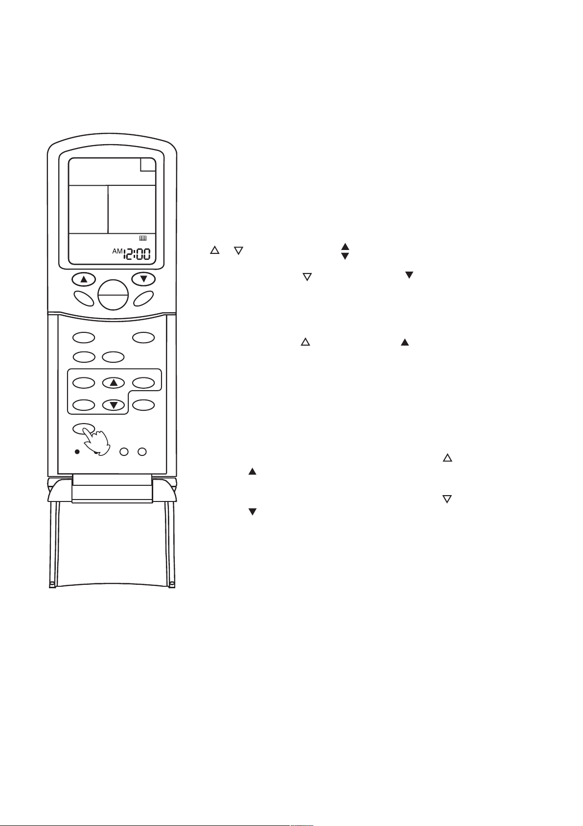
Filter Up/Down
(Only for AB182ACBEA)
A
After the air conditioner has operated for a certain period, dust has
accumulated on the filter, and the filter up/down function can be used
to clean it.
1.Whether unit starts or stops, continuously press FILTER
button for 3 seconds, and enter the filter up/down waiting
status (when unit stops, the yellow TIMER indicator flashes,
and filter and clock indication are displayed on the remote
controller . Only the FILTER button, the temperature buttons
" " " " and time buttons are active).
SWING
MODE
HEALTH
CLOCK
TIMER
FILTER
RESET
CODE
1
TEMP
ON
OFF
FRESH
LIGHT
FAN
SLEEP
SET
HIGH/SO
LOCK
2.Press temperature button or time button in filter
" "
" "
up/down waiting status: the up/down mechanism makes
the filter moving downward and does not stop until it has
reached the maximum limit.
3.Press temperature button or time button in filter
" "
" "
up/down waiting status: the up/down mechanism makes
the filter to moving upward till near the surface board and
then automatically adjusts it to reset (when adjusting to reset,
it will not be controlled by the remote controller till the adju stment is finished).
4.During moving downward, press temperature button
or time button: moving stops.
" "
5.During moving downward, press temperature button
or time button: moving stops.
" "
" "
" "
6.Continuously press FILTER button 3 seconds again to
cancel the filter up/down waiting mode (unit stops, the
yellow timer indicator stops flashing, the filter goes back to
the original position, the remote controller goes back to off
status and only clock is displayed).
Note:
If the filter does not thoroughly go back to the original position, only needs to
operate several times repeatedly.
" High mode " Operation
A
A
U
T
O
TEMP
ON
SWING
MODE
HEALTH
OFF
FRESH
FAN
SLEEP
Outline of operation in "High Mode"
This function is suitable when the set temperature must be
reached in the shortest delay.
The button "HIGH/SO", referred to this function, is effective
in Cooling/Heating mode (not in Auto/Dry/Fan modes).
ON
Press the HIGH/SO button noce
The indication appears on the display of the remote
controller and operation in "High Mode" starts.
The AUTO fan speed is automatically set and the corresponding
indication is also displayed.
LIGHT
SET
HIGH/SO
1
LOCK
OFF
CLOCK
TIMER
FILTER
RESET
CODE
Press the HIGH/SO button twice
If the button is pressed once, the indication is displayed
on the remote controller. If you press the button once again,
the indication disappears, regular operation is restored and fan
speed goes back to the mode set before "High Mode" operation.
NOTICE:
When the air conditioner is operating in " High Mode " , unevenness of room air temperature
may occur due to the intensive operation in a short time.
Anyway, operation in "High Mode", does not last for more than 15 minutes, then regular
operation is automatically restored.

" Soft mode " Operation
A
A
U
T
O
OFF
TEMP
ON
SWING
MODE
HEALTH
CLOCK
TIMER
OFF
FRESH
FAN
SLEEP
SET
HIGH/SO
Outline of operation in "Soft Mode"
Operation in "Soft Mode", more silent, is suitable when noises
should be reduced, e.g.. for reading or sleeping.
The button "HIGH/SO", referred to this operation, is effective
in Cooling/Heating mode (not in Auto/Dry/Fan modes).
ON
Press the HIGH/SO button twice
The indication appears on the display of the remote
controller and operation in "Soft Mode" starts.
The AUTO fan speed is automatically set and the corresponding
indication is also displayed.
FILTER
RESET
CODE
LIGHT
1
LOCK
OFF
Press the HIGH/SO button twice
If the button is pressed once, the indication is disappears
from the remote controller's display. If you press the button
once again, regular operation is restored and fan speed goes
back to the mode set before "Soft Mode" operation.
NOTICE:
When the air conditioner is operating in " High Mode " , unevenness of room air temperature
may occur due to the intensive operation in a short time.
Anyway, operation in "High Mode", does not last for more than 15 minutes, then regular
operation is automatically restored.

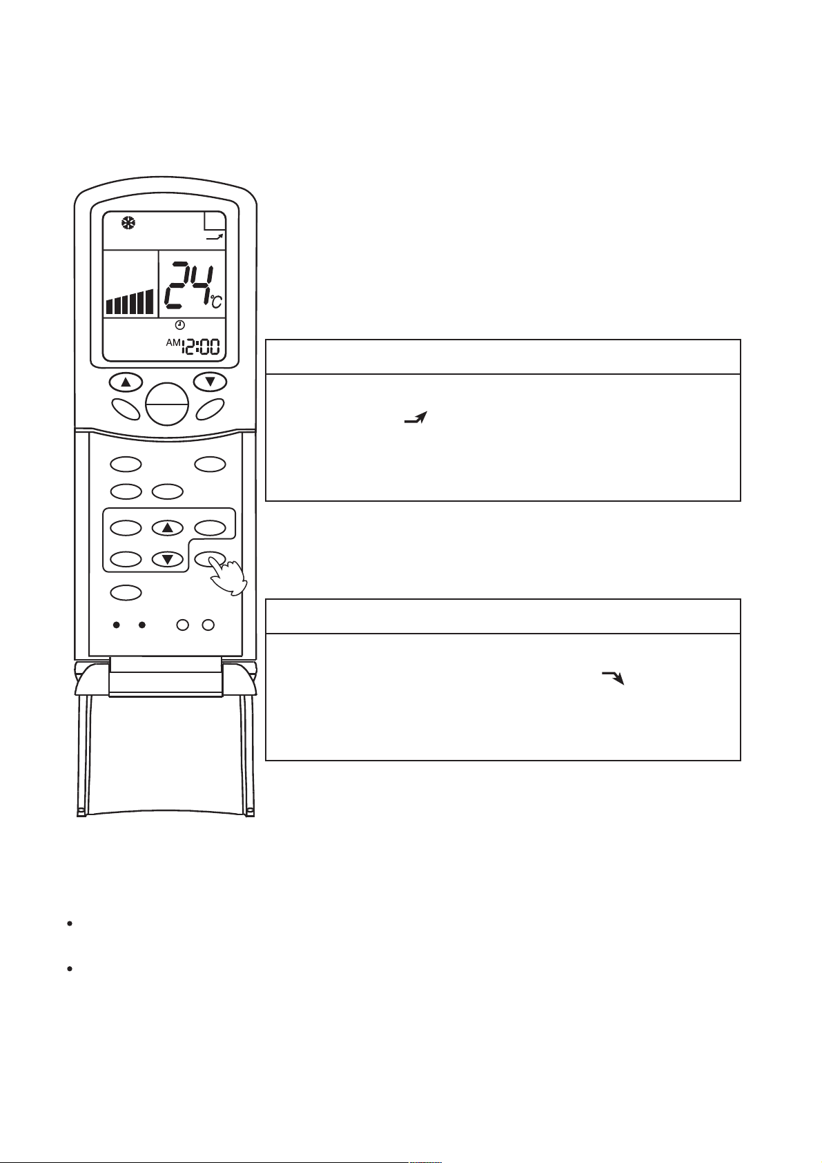
AIR FLOW DIRECTION ADJUSTMENT PROCEDURE-Cassette type
Adjusting up/down air flow direction
Up/down direction can be adjusted by using the SWING button on the remote
controller.
Each time pressing this button, the mode changes in the following sequence.
SWING
Change to the AIRFLOW mode.
SWING
Louver moves in upward and
downward directions continuously.
No indication
(louver stopped)
LOUVER STOPPED
When the LOUVER button is
pushed during SWING mode,
it stops swinging at the just
angle.
CAUTION
Avoid direct air flow to the body for many hours.
Avoid downward blowing operation of cooling mode for many hours.
Do not touch the swing louver during swing operation.
AIR FLOW DIRECTION ADJUSTMENT PROCEDURE-Convertible type
Adjusting up/down air flow direction
Up/down direction can be adjusted by using the SWING button on the remote controller.
Each time pressing this button, the mode changes in the following sequence.
Change to the AIRFLOW mode.
SWING
Louver moves in upward and
downward directions continuously.
CAUTION
Avoid direct air flow to the body
for many hours.
Avoid downward blowing operation of cooling mode for many
hours.
Do not touch the swing louver
during swing operation.
SWING
No indication
(louver stopped)
LOUVER STOPPED
When the LOUVER button is
pushed during SWING mode,
it stops swinging at the just
angle.
Recommendable stopping angle of the louver
COOL
and
DRY
(Horizontal Blowing)
HEAT
(Downward Blowing)
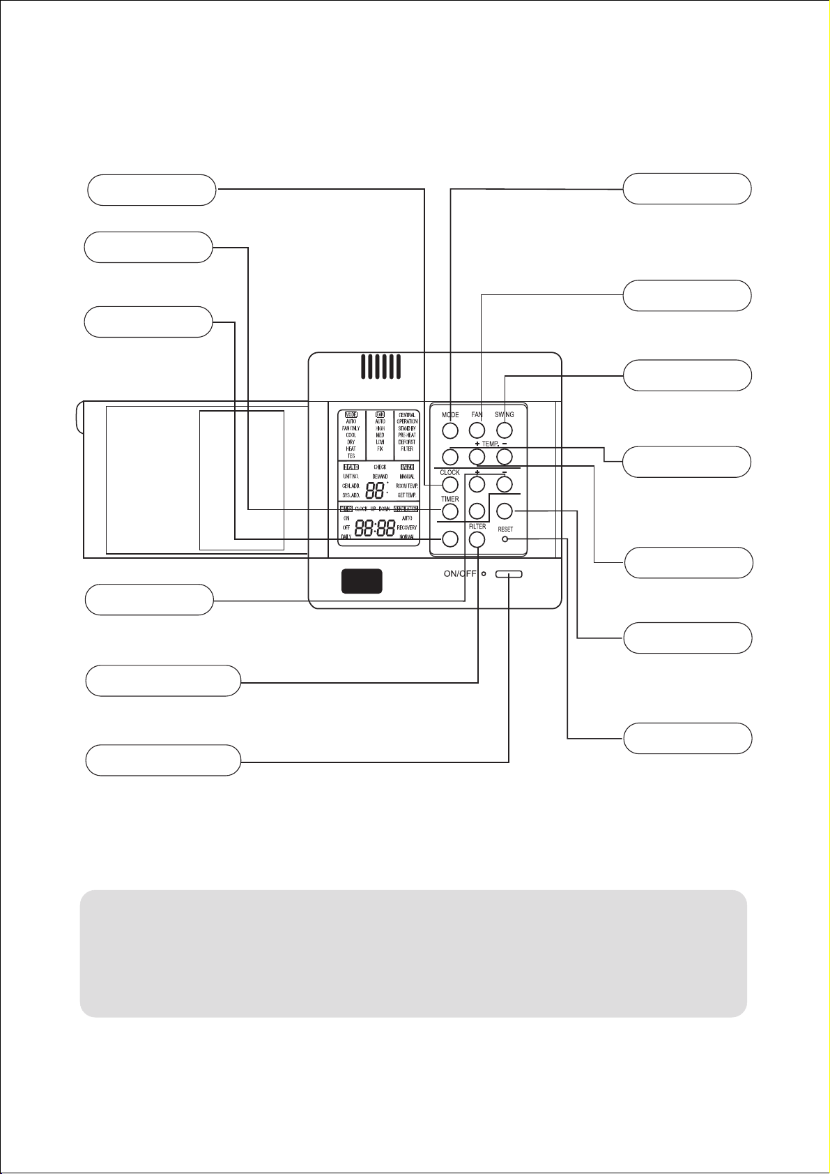
Wired controller functions:
Buttons and functions of the wired controller
CLOCK
Used to adjust time.
TIMER
Used to set timer
mode.
CHECK
Auto-diagnostic
button.
+ -
stands for time plus/minus,
used to adjust time.
FILTER
Filter-cleaned button.
MODE
Used for select
indoor operation
mode.
FAN SPEED
Used for select indoor
air flow.
SWING
Used for setting
indoor swing mode.
HEALTH
HEALTH
C
F
SET RECOVERY
CHECK
Used for setting
indoor health
function.
TEMP + -
Used for changing
set temperature.
RECOVERY
used to switch
over airexchanging mode.
POWER ON/OFF
Used for unit start and
stop.
Cautions:
On cooling only unit, heating
mode is not available.
RESET
Reset correct
mode button.
Note:
The above information is the explanation of
the displayed information therefore varies
with those displayed in actual operation.

Buttons function:
MODE:used for select indoor operation mode.
FAN:used for select indoor air flow.
SWING:used for setting indoor swing mode.
HEALTH:used for setting indoor health function.
TEMP + -:used for changing set temperature.
CLOCK:used to adjust time.
+、-:stands for time plus/minus, used to adjust time.
TIMER:used to set timer mode.
RECOVERY:used to switch over air-exchanging mode.
CHECK:auto-diagnostic button.
FILTER:filter-cleaned button.
RESET:reset correct mode button.
Display description:
[MODE] [AUTO]:auto operation mode
[MODE] [FAN ONLY]:air-throwing mode
[MODE] [COOL]:Cooling operation mode
[MODE] [DRY]:Dehumidification mode
[MODE] [HEAT]:Heating operation mode
[MODE] [HEAT] [TES]:In heating mode, auxiliary electric heater is running. Only when the unit
with auxiliary electric heater is in auxiliary electric heating mode, it will display.
[FAN] [AUTO]:auto fan running

[FAN] [HIGH]:high fan speed
[FAN] [MED]: medium fan speed
[FAN] [LOW]: low fan speed
[FAN] [FIX]: fixed fan speed, it will display only when fixed fan speed is requested to main indoor
unit.
[CENTRAL]: central control mode
[OPERATION] :running mode
[STAND BY] : waiting mode
[PRE-HEAT] : pre-heating mode
[DEFROST]: defrosting mode
[FILTER] : request of filter to be cleaned
[HEALTH]:health function
[UNIT NO.]
[CEN.ADD]:central control address, the address number will display on “88”
[SYS.ADD.]:system address, the address number will display on “88”
[CHECK]:auto-diagnostic, trouble shooting
[DEMAND]:compulsory operation function, when it works, [CENTRAL] will flash
[SWING]:swing mode
[ROOM TEMP.]:indoor ambient temperature
[SET TEMP.]:set admired temperature
[TIMER][ON] :timer function is on, it will switch over in the sequence below:
[ON][OFF] → [ON][OFF][DAILY] →[ ]
[TIMER][OFF] :timer function is off
[TIMER][ON][OFF] :timer function ON-OFF
[TIMER][ON][OFF][DAILY]:timer ON-OFF will switch over in turn daily
[CLOCK]:clock display, the displaying time is the current time of the clock.
[UP]、[DOWN]:indicator of filter elevating
[VENTILATION][AUTO]:auto ventilation mode
[VENTILATION][RECOVERY]:fully heat exchanging ventilation mode
[VENTILATION][NORMAL]:normal ventilation mode
FAN ONLY OPERATION:
1)Start up operation: press the button of ON/OFF, the system will start up, and will display
[MODE][AUTO];[FAN][AUTO];[ROOM TEMP.]+“24℃”;[CLOCK]+”12:00”.
2) Select MODE: press the MODE button, then you will see in the display section [MODE] switch
over in below sequence:[FAN ONLY]→[COOL]→[DRY]→[HEAT]→[AUTO]→[FAN ONLY].
Select [FAN ONLY].
3)Select fan speed: press FAN button, then you see in the display section [FAN] switch over in
below sequence: [HIGH]→[MED]→[LOW]→[HIGH]. Select proper fan speed.
4)Power off: press ON/OFF button, indoor unit will be powered off, there are only time and the
ambient temperature in the screen.

AUTO operation, COOLING, HEATING and DEHUMIDIFICATION operation
1) Start up operation: press the button of ON/OFF, the system will start up, and will display
[MODE][AUTO];[FAN][AUTO];[ROOM TEMP.]+“24℃”;[CLOCK]+”12:00”.
2) Select MODE: press the MODE button, then you will see in the display section [MODE] switch
over in below sequence:[FAN ONLY]→[COOL]→[DRY]→[HEAT]→[AUTO]→[FAN ONLY]. Select
[FAN ONLY].
3) Change set temperature: press TEMP + or – every time, [SET] will display, and set
temperature will increase/reduce 1℃(F).
4) Select fan speed: press FAN button, then you see in the display section [FAN] switch over in
below sequence: [HIGH]→[MED]→[LOW]→[HIGH]. Select proper fan speed.
5) Select [SWING]: press [SWING] button,swing function is valid. Press again, swing function is
invalid.
6) Set [HEALTH]: used to set the indoor health function. Press it once, [HEALTH] will display in
the display section, then indoor health function is valid. Press it again, [HEALTH] will disappear,
then the health function is invalid.
This function is valid only for the unit with health function.
7) Power off: press ON/OFF button, indoor unit is powered off. There are only time and the
ambient temperature in the screen.
Set TIMER operation:
Adjust clock: when powered on, for the first time to set timer function, the clock will be adjusted.
Press “CLOCK” button, and set the current clock. Now, “CLOCK” will flash at the frequency of
2Hz every minute. Press the clock +/- button; the current clock can be adjusted. Until the proper
time comes, press [SET].
TIMER ON operation:
Press TIMER button, and keep pressing it, in the display section [TIMER] will switch over in below
sequence: [ON]→[OFF]→[ON][OFF] → [ON][OFF][DAILY] →[ ]. Select [TIMER] [ON], then
[TIMER] [ON] flashes, press the clock +/- button to adjust the time of TIMER ON, press [SET]
button.
TIMER OFF operation:
Press TIMER button, and keep pressing it, in the display section [TIMER] will switch over in below
sequence: [ON]→[OFF]→[ON][OFF] → [ON][OFF][DAILY] →[ ]. Select [TIMER] [OFF], then
[TIMER] [OFF] flashes, press the clock +/- button to adjust the time of TIMER OFF, press [SET]
button.
TIMER ON-OFF operation:
Press TIMER button, and keep pressing it, in the display section [TIMER] will switch over in below
sequence: [ON]→[OFF]→[ON][OFF] → [ON][OFF][DAILY] →[ ]. Select [TIMER] [ON] [OFF].
Firstly, [TIMER][ON] flashes, press the clock +/- button to adjust the time of TIMER ON, press
[SET]. [TIMER][ON] will be constant on. Then [TIMER] [OFF] flashes, press the clock +/- button

to adjust the time of TIMER OFF, press [SET]. The time sequence of timer on and timer off will
determine the mode is [TIMER] [ON] →[OFF] or [TIMER] [OFF] →[ON].
Note: 1. If the two times are the same, the unit will adjust the state after set time arrives according
to the current state. If current state is in running mode, after set time arrives the unit will switch to
“power off“ state. If current state is in “power off” mode, after set time arrives, the unit will switch to
running mode.
2. When in TIMER setting state, if you do not input any button in continuous 10 seconds, the unit
will think [SET] pressed.
Cancel TIMER operation:
In the timer operation state, press [TIMER] button, the unit will quit from the current timer
operation state, and the set data will be memorized, then enter the next timer mode.
After timer be set, press ON/OFF to cancel timer mode. When in running again, timer mode will
be continuous (without timer).
[FILTER] function
When the wired controller receives the filter-cleaned signal from indoor unit, [FILTER] will display.
After finishing clean, press [FILTER], the sign [FILTER] disappears, and the controller will send
the filter reset signal to indoor unit.
When the sign [FILTER] not display, it is invalid to press [FILTER] in short time.
FILTER ELEVATING function: (only for the unit with elevating function)
In power off state, press [FILTER] for 5 seconds to enter filter elevating set state. In this state, the
sign [FILTER] will flash at the frequency of 2Hz. By pressing [+] TEMP [-], filter can go up or down.
Press TEMP [+], in timer section [UP] will display, while press TEMP [-], in timer section [DOWN]
will display. Press [FILTER] button to quit the mode.
DEMAND operation function:
In the stop state of cooling mode, press [ON/OFF] button for 5 seconds to enter [DEMAND]
cooling operation state, the sign [DEMAND] will display. In the 7-segmet liquid crystal screen of
set temp. section, “0” will display in first position, which shows that No. 0 indoor unit has enter
demand operation. In the second position, “L” will display, in the meantime, [COOL] will flash,
[FAN][AUTO] is constant on. Press TEMP [+] [-] to set different indoor unit. Press [ON/OFF] to
cancel [DEMAND] operation.
In the stop state of heating mode, press [ON/OFF] button for 5 seconds to enter [DEMAND]
heating operation state, the sign [DEMAND] will display. In the 7-segmet liquid crystal screen of
set temp. section, “0” will display in first position, which shows that No. 0 indoor unit has enter
demand operation. In the second position, “H” will display, in the meantime, [HEAT] will flash,
[FAN][AUTO] is constant on. Press TEMP [+] [-] to set different indoor unit. Press [ON/OFF] to
cancel [DEMAND] operation.
VENTILATION mode (only for the unit with fresh air function or heat recovery function)
Press [RECOVERY] button, then the unit will switch over the ventilation mode:
[ ] → [VENTILATION][AUTO] → [VENTILATION][RECOVERY] → [VENTALATION][NORMAL]

→[ ], please select appropriate ventilation mode.
Query indoor malfunction history:
In the state of power on or power off, press [CHECK] button, enter the malfunction-querying
mode of all indoor units in the group. Then [CHECK] and [UNIT NO.] will display, and the actual
indoor numbers will be displayed in some sequence (unit number is in decimals). At the same
time, in the time region, there will be the current malfunction and the latest time malfunction, the
displaying format is [XX:YY], in which XX stands for the current malfunction, if normal, it will
display “――”; YY stands for the latest time malfunction. The failure code of every unit will display
for 3 seconds. After the failure codes of all indoor units in the whole group are displayed, the
mode will quit automatically.
Clear abnormal state and malfunction history:
In normal state, press [CHECK] button for 5 seconds to clear abnormal states, at the same time,
wired controller will send the data of “clear abnormal state”, but the malfunction history still
retains.
In normal state, press [CHECK] button for 15 seconds, except for malfunction states, the
malfunction history in wired controller will be cleared.
Query indoor performance state:
In normal state, press both buttons of [CHECK] and [FILTER] for 5 seconds, in the set
temperature region in the screen, [XX] will display, XX is indoor number, which can be selected by
pressing [TEMP] [+] [-]. In the timer region in the screen, [YZZZ] will display, in which Y stands for
data type, ZZZ stands for the corresponding data. which can be selected by pressing [CLOCK] [+]
[-].
Y ZZZ Type
A Indoor capacity (W) Nominal cooling
capacity/10, decimal
B Request of indoor capacity(Hz) Actual value, decimal
C Temperature of indoor ambient
temp. sensor TA
d Temperature of indoor gas pipe
sensor TC1
E Temperature of indoor liquid pipe
sensor TC2
F Open degree of indoor PMV Actual value, decimal
g Preset ―――
H Outdoor total capacity Actual value, decimal
Actual value, decimal
Actual value, decimal
Actual value, decimal
In check mode, press [CHECK] to quit the check mode, and go into normal running mode.

How to change the function switches?
No. Type State of
Function description
switch
J01
J02
J06
J07
J03
SW01
①
SW01
②
D1
D2
Changeover of Wired
controller and central
controller
Changeover of type of
wired controller
Selection of room temp.
sensor
Auto reset after power
failure
Display of room
temperature
Changeover of master or
slave controller
℃ or ℉
Shorten time function
Compulsorily defrost
Connected Central controller
Cut off Wired controller
Connected Set as simple controller
Cut off Set as standard controller
Connected Use the sensor in the wired
controller
Cut off Use the sensor in the indoor unit
Connected Common control
Cut off Auto reset after power failure
Connected Yes
Cut off No
ON Set as slave controller
OFF Set as master controller
ON
OFF
Connected Indoor unit in shorted time
Cut off Common control
Connected Send compulsorily defrost signal
Cut off Common control
℉
℃
function
to indoor unit
Note: The switches in grey can be operated after opening the cover of wired
controller.

Electrical functions of wired controller:
1.Switch over method: wired control master unit/wired control slave
unit/remote control unit
Control method
Socket
/jumper
CN23 Short circuit Not short circuit Not short circuit
CN30 Short circuit Short circuit Not short circuit
CN21 Blank Blank To remote receiver
J19 Short circuit Short circuit Cut circuit
Signal terminal block A,B,C connected
Function difference between master wired controller and slave one:
Contrastive items Master wired controller Slave wired controller
Function All of functions Only with below functions:
Wired control
master unit
Wired control
slave unit
B,C connected to
to wired controller
wired controller
Remote control unit
board
A,B,C not connected
to wired controller
ON/OFF, MODE, FAN SPEED,
SET TEMP., SWING
2. Wiring connections of wired controller:
A
indoor 1 indoor 2
wired controller
B
indoor 1
wired controller
1
A
wired controller
2
B
wired controller
C
3
polar wire
C
indoor N
wired controller wired controller
indoor 1
wired controller
123
polar wire
ABC
wired controller
indoor 15
polar wire
ABC
wired controller
indoor 16
(master unit)
wired controller
control wiring of wired controller, polar.
ABC
wired controller
There are three methods to connection wired controller and the indoor
units:
A. One wired controller can control max. up to 16 sets of indoor units, and
1

3 pieces of polar wire must connect the wired controller and the master
unit (the indoor unit connected with wired controller directly), the others
connect with the master unit through 2 pieces of polar wire.
B. One wired controller controls one indoor unit, and the indoor unit
connects with the wired controller through 3 pieces of polar wire.
C. Two wired controllers control one indoor unit. The wired controller
connected with indoor unit is called master one, the other is called slave
one. Master wired controller and indoor unit; master and slave wired
controllers are all connected through 3 pieces of polar wire.
3. Communication wiring:
The wired controller is equipped with special communication wiring in the
accessories. 3-core terminal (1-white 2-yellow 3-red) is connected with the
terminal A、B、C of wired controller respectively.
The communication wiring is 4 meter long; if the actual length is more than
it, please distribute wiring according to below table:
Communication wiring length(m) Dimensions of wiring
<100 0.3mm2X3-core shielded wire
≥100 and <200 0.5mm2X3-core shielded wire
≥200 and <300 0.75mm2X3-core shielded wire
≥300 and <400 1.25mm2X3-core shielded wire
≥400 and <600 2mm2X3-core shielded wire
※ One side of the shielded sheet of communication wire must be earthed.

3.4 Refrigerant Diagram
Piping Systematic Diagram for Cooling/Heating Type Air Conditioner
Indoor Unit
Capillary Tube
Cooling Operation
Stop
Valve
Heat Exchanger
Stop
Valve
Heating Operation
Quieter
Outdoor Unit
Filter
One-way Valve
Reversing Valve
Heat Exchanger
Compressor

4 ELECTRICAL DATA
2HP cassette type wiring diagram

2HP convertible type wiring diagram

14000BTU/h mid ESP duct type wiring diagram
Note:
1.Dashed parts are not available
2.Central controller is optional
3.P16 and P17 are used for room card function

18000BTU/h mid ESP duct wiring diagram
Note:
1.Dashed parts are not available in duct type
2.Central controller is optional
3. P16 and P17 are used for room card function

Outdoor wiring diagram
2HP OUTDOOR UNIT WIRING DIRGRAM
TRANS.
BL
7
8
W
5
3
NONOCOM
COM
642
W
B
1
RELAY
NC
NC
GR
FAN MOTOR
SPEED
CONTROLLER
2
HIGH PRESSURE SWITCH
P
LOW PRESSURE SWITCH
1
OUTDOOR AMBINENT SENSOR
OUTDOOR PIPING SENSOR
COMPRESSOR VENT SENSOR
R:RED W:WHITE GR:GRAY
BL:BLUE B:BLACK Y/G:YELLOW/GREEN
CN1
CN2
CN10
CN3
CN12
CN11
S
TO INDOOR UNIT
CIRCUIT
DETECTOR
CN4
Y/G
BWR
Y/G
N3
FAN
N2
ST
HB
N1
C
A
V
E
0
S
3
4
NOTE:
1. Dashed parts
2. Dashed parts is optional for Low Ambient Temp.
Cooling,and there is no relay in only Cooling type
5
U
2
F
/
A
5
1
.
3
N
T
FAN MOTOR CAP.
W
B
BL
4-WAY VAVLE
BL
WIND
CRANK
HEATER
W
R
R
B
S
Y/G
C
M
COMPRESSOR
is not available for only Cooling type
M
FAN MOTOR

Circuit for 14000BTU/h, 18000BTU/h outdoor unit:
54321
6
N
250
D
250
L1
4007
62K/3W
D1
R4
S
250
C
CT 1
0057W
B
CN3
XHB2B
2
1
2
1
PIP ROOM
CN12
XHB2B
A
1 2 3 4 56
C16
22uF/250V
R1
200K
D2
4007
R2
62K/3W
R3
62K/3W
D3
4007
R15
10K/0.5W
D4
4007
R16
10K/0.5W
CN10
VHB2B
CN2
VHB2 B
+5
D5
4148
D14D15
D13D12
R13
470
RW
102
R24
5.1K
+5
R25
5.1K
C20
104
C3
103
R5
33K
IC1
R6
C2
2.2K
103
2
1
2
1
R10
R11
1K
1K
C21
470UF/16V
C17
4.7UF/50V
C22
4.7UF/50V
+5
3
C7
104
TLP371
IC2
C27 103
C10 103
C12 103
C11 103
C6
104
+5
R27
10K
Vout
TLP521-1
R17
10K
RG1 7 8 05
GND
2
+5
+5
R7
10K
R8
1K
103
C4
R19
R18
10K
+5
Vin
R20
10K
10K
TEST
4MHz
OSC1
R23
560
+12 1
1
C8
104
2200UF/35V
D8 D11
C1
1
IRQ
2
PTA0
3
R9
LED1
1M
VSS
4
OSC1
5
OSC2/PTA6
6
PTA1
7
VDD
8
PTA2
9
PTA3
10
PTB7
11
PTB6
12
PTB5
13
PTD7
14
PTD6
D10D9 L1
R12
560
IC3
MC68HC908JL3ECP
CN1
XHB2P3
1
2
RST
PTA5
PTD4
PTD5
PTD2
PTA4
PTD3
PTB0
PTB1
PTD1
PTB2
PTB3
PTD0
PTB4
CN11
XHB2B
CN4
RTB- 1 . 5 - 2 P
D
D4
+12
4004
+5
C5
104
28
27
26
25
24
23
22
21
20
19
18
10K
17
R21
16
15
R26
C25
47K
104
2
1
1
2
3
4
5
6
+5
IC4
ULN2003A
A1
A2
A3
A4
A5
A6
A77Q7
GND8VCC
16
Q1
15
Q2
14
Q3
13
Q4
12
Q5
11
Q6
10
9
D4
4004
JK5
JTN1S-TMP-F-DC12V
JK2
JQ1A
JK7
OJE-SS-112DM
FAN
N2
N1
HB
YJ
ST
N3
C
B
FUSE
T3.15A/250V
2
0.1UF/250V
LX102
LX1
C23
C24
VR
S1 4 K 3 5 0
0.1UF/250V
250
Title
AU242ACBEA
Number RevisionSiz e
B
Date: 13-Nov-2003 Sheet of
File:
250
N
0010451493
A

0010451167 PCB information – circuit diagram
XT1
INOUT
2200uF
LED5
2
E1
1
VDD
R8 10
8.00M
D17
1N4148
D1-D4
C34
104
D12
4148
D13
4148
103
C24
R63
LED4
27K
D15
4148
D14
4148
1K
4.7uF
R141KR15
E6
R7 10
R25
4
R13
1K
D16
4148
2.4K
1
2
3
4
5
6
7
8
1
2
3
4
5
6
7
8
4.7K
R27
4.7K
R26
C14 103
C15 103
C16 103
R61 20K
R62 20K
R60 20K
4.7uF
E7
+5
1
CN6
CN20
CN19
VDD
IC1
2003
104
C32
IC2
2003
104
C31
N5
9013
N4
9013
1
4
CN4
1
CN5
A
B
C
12345
12345
16
15
14
13
12
11
10
9
+12
16
15
14
13
12
11
10
9
+12
C35
104
C36
104
T1
TRAN1-2
C20
103
0.1UF/275V
LB1
CN1
C2
+12
RL6
JQ1AP-A
JQ1P-A
JQ1P-A
RL5
JQ1AP-A
RL4
JQ1AP-A
RL3
JQ1AP-A
RL2
JQ1AP-A
RL1
JQ1AP-1
BUZ1
100
R67
+5
R65
200K
R20
1K
2.2uF
4.7K
R35
220
IC8
R9
E8
TLP521-1
J1 J2 J3 J4 J5 J6 J7 J8 J9 J10
0.1UF/275V
RL8
RL7
+12
680
R6
1N4007
D11
C1
FUSE1
100K/1W
187
T3.15A/250V
187
187
187
RC3
0.033uF+120
187
RC1
0.033uF+120
187
RC2
0.033uF+120
187
187
187
187
187
R1
187
1 P2-P6
RV1
1 P1
1 P14
1 P13
1 P12
1 P11
1 P10
1 P9
1 P8
1 P7
CN7
1
1
P16
1
P17
P15
187
D10
1N4007
+5V
GND
CN17
CN16
CN12
CN11
CN15
R43
10K
R39 10K
R22 1K
AB32
+5
CGMXFC
VDDAREF
C33
104
N1 9013
OSC1
OSC2
VSSA
VDDA
VREFH
NOP
AVss
NOP
SW1
+5
470uF/16V
N3
9013
N2
9013
E3
R11
R32
4.7K
R33
1K
64
63
62
61
60
59
58
57
56
55
54
53
52
51
50
49
48
47
46
45
44
43
42
41
40
39
38
37
36
35
34
33
C12
103
103
R5 33K
R2
10K/0.5W
LED3
10K/0.5W
R3
1
CN23
1
2
2.2K
D9
CN14
+12
4
+5
1
R53 10K
+5
CN13
1
7
2
1
D19
4148
+12
DL1
2
DL2
1
+5
+5
1
2
1
1
R4
R54
N8
9013
R19
9013
N10
5
6
7
8
R44
R45
R46
CN22
2
1
C3
1K
103
10K
LED1
R12
1K
C6
102
R57
IC4 MAX487
DI4GND
DE
A
/RE
B
RO
VCC
C25 104
10K
10K
10K
C4 103
1
23
R58
N6
N7
560
4.7K
3
2
1
1K
R18
1K
R17
1K
R16
IC6
TLP371
6
5
1
2
LED2
IC7TLP521
4
9013
4.7K
R28
9013
4.7K
R29
1K
R23
C23
103
C26 104
IC5
1
2
3
4
C17
103
C18
103
C19
103
1
24
CN10
R36
10K
24C01A
EEPROM
RB1
330
R10
+5
+5
4.7K
R30
N9
1K
C8
R21
102
+5
R55
D18
1N4148
10K
E9
C27
104
1uF
C5 102
10K
R51
10K
+5
8
7
6
5
J7J8J9
J10
R59
10K
R56
R52
10K
+5v
10K
R50
+5
C9
103
J5
J6
1/60
CHECK
104E4100uF
C22
C29
R24
1K
4.7K
R31
+5
C7
102
IC3
1
2
IRQ/50Hz
3
RESET
4
NOP
5
6
7
BEEP
8
IR
9
10
11
12
487
13
NET-O
14
NET-I
15
P/G
16
P/G
17
NOP
18
19
20
NOP
21
Vss
22
Vdd
23
SCL
24
SDA
25
26
A
27
B
28
C
29
D
30
31
32
C10
103
RB3RB2 RB5
J4
C11
103
RB4
SW2
J1J2J3
C21
103
+5
330
+5
C28 104
W2
INOUT
7805
TLP741/541
R49
C13
103
+5v
+12
R41
R64
56K
IC10
IC9
TLP521
+5
+5
R48 10K
R47 10K
R40 10K
W1
7812
10K
R34
4.7K
R66
1M
10K
E5
4.7uF
CN8

0010451167 PCB information – characters on board(horizontal)

0010451167 characters on board(vertical)

0010451167 PCB information – port and definition
P1——connect to external power supply, live line: L (220VAC)
P2——connect to external power supply, neutral line: N (0VAC)
P3、4、5、6——control external load, neutral line: N1、N2、N3、N4(0VAC)
P7——control external load, electrical heat: HEAT (control output 220VAC)
P8——control external load, health function: OXYGEN (control output 220VAC)
P9——control external load, humidification: HUMI (control output 220VAC)
P10——control external load, SWING(control output 220VAC)
P11——control external load, WATER PUMP(control output 220VAC)
P12——control external load, indoor fan motor low speed: L(control output
220VAC)
P13——control external load, indoor fan motor mid speed: M(control output
220VAC)
P14——control external load, indoor fan motor high speed: H(control output
220VAC)
P15 ——communication with fixed frequency single outdoor unit:
COMM(0~220VAC)
P16——input control, signal live line: L’(220VAC)
P17——input control, signal neutral line: N’(0VAC)
CN1——input port of transformer (220VAC)
CN2——input port 1 of transformer (no use)
CN3——input port 2 of transformer (no use)

CN4——input port 3 of transformer (1-2、14VAC,3-4、12VAC)
CN5——input control, connecting port to wired controller: CONTROLLER(1.
power supply: 12VAC, 2. power supply: 0VAC, 3. communication: COMM.)
CN6 ——input control, ambient temp.-coil temp. sensor connecting port:
ROOM/PIPE(1-2、ROOM,3-4、PIPE。)
CN7——control external load, fresh air control: FRESH(1. blank, 2. power
supply 0VDC, 3. control output: 12VDC.)
CN8——input signal: FREEZE(no use)
CN9——input control(no use)
CN10——communication with fixed frequency single outdoor unit: (0~12VDC)
CN11——input signal, door switch: DOOR(1-2 short circuit is normal, cut off
P8 output)
CN12——input signal, external alarm input: ALARM(1-3 short circuit is normal,
if cut off, air conditioner stops work.)
CN13——input signal, wiring port of remote receiver board: RECEIVE BOARD
(1. power supply 5VDC, 2. power supply 0VDC, 3. remote signal, 4. signal output of
running lamp 0VDC, 5. signal output of timer lamp 0VDC,6. signal output of power
lamp 0VDC, 7. signal output of water pump running lamp 0VDC)
CN14——control external load, elevating function (1. signal of door switch
close, 2. output of elevating direction control 0VDC, 3. output of elevating power
control 0VDC, 4. power supply 12VDC)
CN15——input signal, water level of float switch (1-3 short circuit is normal, cut

off shows that level exceeds the limitation)
CN16——input control, wiring port of central controller: REMOTE(1、RS485-B,
2、RS485-A。)
CN17——output signal, output signal of failure alarm, control external load,
12V/ALM(1. control output 0VDC, 2. power supply 12VDC)
CN18——output signal (no use)
CN19——control external load, swing 1(1、16VDC,2、0VDC,3、0VDC,4、
0VDC,5、0VDC.)
CN20——control external load, swing 2(1、16VDC,2、0VDC,3、0VDC,4、
0VDC,5、0VDC.)
CN21——input signal, spring switch, CHECK(1、input signal of earthing, 2.
power supply 0VDC)
CN22——short circuit means selecting single split communication type.
CN23——short circuit means selecting multi split communication type.

0010451167 PCB information – function selection(ON is 1, OFF is 0)
The standard condition for PCB in factory
SW1:4 bits are OFF
SW2:4 bits are OFF
SW3:4 bits are ON
SW4:2 bits are ON
SW5:4 bits are ON
SW1-1——address selection of central controller 0, address selection of wired
controller 0
SW1-2——address selection of central controller 1,address selection of wired
controller 1
SW1-3——address selection of central controller 2,address selection of wired
controller 2
SW1-4——address selection of central controller 3,address selection of wired
controller 3
SW2-1——address selection of central controller 4
SW2-2——address selection of central controller 5
SW2-3——address selection of central controller 6
SW2-4——logistic relationship of control function(door card control and remote/
wired control)0 means logistic relationship is “and”, 1 means the later coming is
preferential.
J1,SW3-1——function selection-control type: 1 means remote control, 0 means

wired control.
J2,SW3-2——function selection-temperature compensation in heating mode:
1means “yes”, 0means “no”.
J3,SW3-3——function selection-outdoor communication: 1means “yes”, 0means
“no”. This PCB must be 1.
J4,SW3-4——function selection-heat pump unit: 1means “heat pump”, 0means
“cooling only”.
1/60——test in short circuit, but in operation short circuit mustn’t be permitted.
CHECK ——short spring switch control, it also can be used as switch of
convertible type except for testing.
J5,SW4-1——function selection-elevating function: 1means “yes”, 0means “no”.
J6,SW4-2——function selection –health function: 1means common (indoor fan
motor running); 0 means special (indoor, outdoor running).
J7,SW5-1——function selection –swing mode: 1 means common(simultaneous
motor), 0 means special (swing motor).
J8,SW5-2——function selection – system combination: 1means fixed frequency
single unit, 0 means fixed frequency multi split.
J9,SW5-3——function selection –group control: 1 stands for the master unit (its
address in wired controller is 0), 0 stands for the slave units (the address should be
set by the dip switch, their addresses only can be in the range: 1~15)
J10,SW5-4——function selection –preset: 1 no meaning, 0 no meaning

0010451167 PCB information- control type
Control type selection between remote and wired: select by dip switch J1, SW3-1
(1 means remote control;0means wired control).
For remote control type, please use remote controller YR-H71, and a remote
receiver is equipped with indoor unit. For wired control type, wired controller
YR-E12 will be used, 3-core shied wire is equipped with indoor unit.
Door card control: controls ON/OFF, the start up setting will comply with last time
request memorized according to condition memorize function. Its difference with
emergency switch of convertible type unit lies: the emergency switch control will
perform in the condition: 24degrees, auto fan speed in auto mode.
The function combination between door card and remote/wired control type: select
by dip switch: SW2-4(0 means “and”, 1 means later coming is preferential.)
Dip switch position in wired control type: Only one indoor unit of all indoor units
connected with wired controller is the master unit, whose address is 0, function
selection switch(J9,SW5-3)is 1. The others are slave units, and the quantity can be
0~15, whose addresses are(SW1:1~4)from 1 ~15, and cannot repeat.
Wiring request in wired control type: the wired controller ports A-B-C are
connected with indoor port CN5(1-2-3) through 3-core shield wire. Requirements:
1. Port A only connects with either of indoor port CN5(1)
2. Port B connects with port CN5 (2) of all indoor units.
3. Port C connects with port CN5 (3) of all indoor units.

Dip switch position in central control type: the addresses (SW1:1~4;SW2:1~4)
of indoor units connected with central controller can not repeat. In principle, they
should be in the order from small to big.
Wiring request in central control type: port A-B is connected with indoor port
CN16(A-B)through 2-core shield wire. Requirements:
1. Port A connects with port CN16(A)of all indoor units.
2. Port B connects with port CN16(B)of all indoor units.
When only use remote control type, please select remote control unit, and install
according to installation manual, there is no other special request.
When only use wired control type, please select wired control unit, and install
according to installation manual. When control multi indoor units, take care the
requirements of dip switch and wiring, there is no other special request.
When only use central control type, please firstly install according to air conditioner
requests and set the dipswitch, there is no other special request.
When central control type(128×)and remote control type are used simultaneously,
set the dip switch according to central control type, there is no other special request.
When central control type(128×)and wired control type (16×)are used
simultaneously, max. indoor units sets: 128×16 can be controller. Address setting of
central controller can be met firstly, and then modulate the address setting of slave unit
wired controlled.

4.4 Thermostat chart (Sensor resistance-temperature graph)
Indoor
Outdoor
Ambient temperature sensor Coil temperature sensor
5K 10K
Ambient temperature sensor Coil temperature sensor Compressor temperature sensor
15K 50K 46.5K
R(25℃)=10K (Indoor unit Piping sensor)
Therameter Sensor
temperature(℃) resistance(KΩ) temperature(℃) resistance(KΩ)
-25
116.0
-20 87.42 50 3.788
-15
66.53
-10 51.8 60 2.660
-5 39.55 65 2.223
0 30.88 70 1.912
5 24.30 75 1.630
10 19.20 80 1.395
15 15.38 85 1.200
20 12.36 90 1.035
25 10.00 95 0.8967
30 8.141 100 0.7796
35 6.668 105 0.6802
40 5.492 110 0.5955
45 4.549
55 3.170
R(25℃)=23K (Indoor unit ambinent sensor)
Therameter Sensor
temperature(℃) resistance(KΩ) temperature(℃) resistance(KΩ)
-10 139.5 60 5.243
-5 105.3 65 4.336
0 80.14 70 3.603
5 61.51 75 3.008
10 47.58 80 2.522
15 35.36 -20 251.8
20 27.93 -19 235.9
25 23.00 -18 223.1
30 18.30 -17 210.1
35 14.65 -16 197.9
40 11.79 -15 186.5
45 9.556 -14 176.9
50 7.780 -13 165.9
55 6.371 -12 156.5

5 PERFORMANCE CURVES
5.1 PERFORMANCE CURVES
a
Cool capacity graph
7.00
6.50
20
b
EER graph
6.00
5.50
5.00
Capacity(KW)
4.50
4.00
5.00
4.00
3.00
EER
2.00
1.00
-5 5 15253543
-5 5 15253543
Outdoor temperature( )
Outdoor DB(
)
Indoor
DB(
Indoor
DB(
22
25
27
30
32
)
20
22
25
27
30
32
)

c
Heat capacity graph (only heat type available)
8.00
7.50
7.00
6.50
6.00
16
18
20
5.50
5.00
4.50
Capacity(KW)
4.00
3.50
3.00
-7 -5 0 7 10 15
Outdoor DB(
COP graph (only heat type available)
d
4.00
3.50
22
24
26
28
Indoor
DB(
)
)
16
18
20
3.00
22
COP
24
26
2.50
28
Indoor
2.00
DB( )
-7 -5 0 7 10 15
Outdoor DB(
)

5.2PERFORMANCE CURVE
F-C curve-COOLING
C-F
6000
5000
4000
3000
2000
Capacity (W)
1000
0
35 40 50 55 60 65 70 80 90 100 110 120
Frequency(Hz)
F-C curve –HEATING
6000
5000
4000
3000
2000
Capacity(W)
1000
0
35 40 50 55 60 65 70 75 80 90 100 110 120
C-F
Frequency(Hz)

5.3Air-pressure curve
Standard static pressure
900
800
700
600
500
400
300
Air volume (m3/h)
200
100
0
50Pa 40Pa 30Pa 20Pa 10Pa 0Pa
A-P
middle
speed
low speed
super-low
speed
Static pressure
50Pa static pressure
1000
900
800
700
600
500
400
300
Air volume (m3/h)
200
100
0
50Pa 40Pa 30Pa 20Pa 10Pa 0Pa
A-P
High Speed
middle speed
low speed
static pressure

6 Charts
6.1NOISE LEVEL CHARTS
6.1.1 Cassette type
AB142ACBIA
60
50
40
30
20
COOLING
High
Med
Low
SOUND PRESSURE LEVEL
10
0
25 63 125 250 500 1K 2K 4K 8K 16K
1/2 OCT BAND CENTER FREQUENCY(Hz)
60
50
40
30
20
10
SOUND PRESSUR LEVEL(dB)
0
25 63 125 250 500 1K 2K 4K 8K 16K
HEATING
High
Med
Low
1/2 OCT。BAND CENTER FREQUENCY (Hz)

6.1.2Convertible type
60
50
40
30
20
10
SOUND PRESSURE LEVEL (dB)
0
25 63 125 250 500 1K 2K 4K 8K 16K
1/2 OCT BAND CENTER FREQUENCY(Hz)
COOLING
outdoor
High
Med
Low
60.0
50.0
40.0
30.0
20.0
10.0
0.0
SOUND PRESSURE LEVEL (dB)
25 63 125 250 500 1K 2K 4K 8K 16K
1/2 OCT BAND CENTER FREQUENCY (Hz)
HEATING
Outdoor
High
Med
Low

6.2.Air Velocity distribution +Temperature distribution
1) Cassette type
a. Cooling / Air Velocity Distribution
Cooling
Blowy angle:40
Air Velocity Distribution
421
b. Cooling / Temperature Distribution
Cooling
Blowy angle:40
Temperature Distribution
25
27
m/s
22
m/s
102
22
25
27
2
0
4
2
0421
12
0
4

c. Heating / Air Velocity Distribution
Heating
Blowy angle:70
Air velocity Distribution
421
d. Heating / Temperature Distribution
Heating
Blowy angle:70
Temperature Distribution
m/s
m/s
10204
2
27
25
27
25
2
22
421
012 4
22
0

2)Convertible type
a) Grounding
a. Cooling / Air Velocity Distribution
Cooling
Blowy angle:25
Air Velocity Distribution
2.4
1.5m/s
0.5m/s
1.0m/s
0
b. Cooling / Temperature Distribution
Cooling
Blowy angle:25
Temperature Distribution
2.4
22
0
5.5
27
25
5.5

c. Heating / Air Velocity Distribution
Heating
Blowy angle:5
Air velocity Distribution
2.4
m/s
0.5m/s
1.0m/s
0
d. Heating / Temperature Distribution
Heating
Blowy angle:5
Temperature Distribution
2.4
27
0
5.5
22
25
5.5

b) Ceiling
a. Cooling / Air Velocity Distribution
Cooling
Blowy angle:25
Air Velocity Distribution
2.4
0
m/s
1.0m/s
0.5m/s
5.5
b. Cooling / Temperature Distribution
Cooling
Blowy angle:25
Temperature Distribution
2.4
22
0
25
27
5.5

c. Heating / Air Velocity Distribution
Heating
Blowy angle:65
Air velocity Distribution
2.4
m/s
0.5
0
d. Heating / Temperature Distribution
Heating
Blowy angle:65
Temperature Distribution
2.4
27
25
22
0
5.5
5.5

3)Duct type
cooling
air discharge angle
Air Velocity distribution
2.4
1.8
5
0.5
2.4
1.8
2.4
0
cooling
air discharge angle 5
Temperature distribution
0
heating
air discharge angle 45
Air Velocity distribution
5.5
22
25
27
5.5
1.8
1.0
0
0.5
5.5

2.4
1.8
heating
air discharge angle 45
Temperature distribution
27
25
0
22
5.5

7 ELECTRICAL CONTROL FUNCTIONS
7.1 Control Features
The brief introduction includes those for each item of various types of air conditioners and
The brief introduction includes those for each item of various types of air conditioners and
their electric control functions.
their electric control functions.
7.1 Brief introduction of electric control 7.1 Brief introduction of electric control
(1) Automatic run (1) Automatic run
a. Cooling-heating type
After the machine being started and running mode changes to AUTO, the system will
decide running mode according to difference between the present room temperature and
setting temperature, then runs as the decided mode. In the following selections, Tr means
room temperature and Ts means setting temperature.
Select running mode according to the following conditions at the first time to enter Auto
mode:
TrTs- 3 to select cooling mode (with setting temperature being Ts +3)
Tr<Ts-3 to select heating mode (with setting temperature being Ts)
After the system entering auto run mode, the running mode can convert automatically
according to variation of room temperature between cooling, blowing and heating in the way
shown as the chart below:
R
t
b. Single Cooling Type
Select running mode according to the following conditions at the first time to enter Auto
mode:
Tr
After the system entering auto run, the running mode can convert automatically
according to variation of room temperature between cooling and blowing functions in the way
shown as the chart below:
f
a
l
l
i
n
g
o
e
o
m
m
p
e
r
a
t
u
r
e
Cooling
Ts-3
Ts + 3 to select cooling mode
Tr < Ts + 3
to select blowing mode
R
t
f
a
l
l
i
n
g
o
e
o
m
m
p
e
r
a
t
u
r
e
Cooling
Cooling
Blowing
Heating
Cooling
Blowing
Ts+3
Ts-3
Ts+3
temperature
rising
temperature
rising
Room
Room
Ts-3
Blowing

(2) Auto Selection of Wind Speed
In the following, Tr means room temperature while Ts means setting temperature.
a. During cooling program
the present speed has continued for 3 minutes while conversion from the high to low needs
no time delay. The chart below is the sketch map of conversion:
Temperature
falling
conversion of wind speed from the low to high won’t work until
High speed
3
Ts
High speed
Ts
2
Medium speed
Medium speed
Ts
1
Temperature
rising
Ts
Low peed
Low speed
b. During heating program
from the low to high won’t work until the present speed has continued for 3 minutes while
conversion from the high to low needs no time delay. The hart below is the sketch map of
conversion:
Temperature
falling
applicable for cooling-heating type , conversion of wind speed
Low speed
Ts
Ts
2
Temperature
rising
Ts
Ts
Low speed
1
Medium speed
3
Medium speed
High speed
High speed
(3) Dehumidifying program
In the following, Tr means room temperature while Ts means setting temperature.
a. After the system entering dehumidifying program, the compressor, outdoor and indoor
blowing fans run according to the following rules:
(1) Tr > Ts + 2
, the compressor and outdoor blowing fan run continuously while indoor

blowing fan runs at setting wind speed. This working area is defined as area A.
(2) Ts
(3) Tr < Ts, the compressor and outdoor blowing fan stop working while outdoor blowing
a. After dehumidifying program starting, the system converts between A, B and C areas
according to variations of room temperature with running mode being shown as the chart
below:
Tr Ts + 2 , the compressor and outdoor blowing fan run for 10 minutes then
pause for 6 minutes, while indoor blowing fan runs at low wind speed. This working
area is defined as area B.
fan runs at low wind speed. This working area is defined as area C.
Room
temperature
falling
Area A
Area A
Ts 3
Ts 1
Area B
Area B
rising
Ts
Room
temperature
Ts 1
Area C
Area C
(4) Cutoff protection against overload and overheat
During heating program, if the indoor blowing fan has been started and the compressor
has been running more than 2 minutes, and the temperature of indoor coil pipe (Ticp)
> 64
blowing fan has kept stop state for 45 seconds, then it will restore rotation; If Ticp > 67
and such temperature has last for 10 seconds, the compressor will stop running and
indoor blowing fan run according to conditions as it reaches setting temperature. When
Ticp < 58
compressor and outdoor blowing fan will restore normal running.
Cutoff protection for heating current
After 60 seconds from the compressor being started, if CT current exceeds I1 (9.2A) and
such case has kept 5 seconds, the outdoor blowing fan will stop. If 45 seconds has passed
after the outdoor blowing stops and the current of the compressor is less than I2 (7.5A), the
blowing fan will restore running. If CT current exceeds I3 (14.3A) and such case lasts for 3
seconds, the compressor and outdoor blowing fan will stop. The compressor will not restore
running until 3 minutes passes with CT current less than 12A.
(5) Cool wind prevention during heating program
At the first time entering heating program or after ending the latest frost removal, if the
temperature of indoor coil pipe (Ticp) < 28
28
compressor has been running for more than 4 minutes, the indoor blowing fan will run at
, the outdoor blowing fan will stops running; If Ticp ≤ 50 and the outdoor
, and the compressor has kept stop state over 3 minutes, then the
, the indoor blowing fan will stop running; If
Ticp < 38 , the indoor blowing fan will run at low speed; If Ticp > 38 or the

setting wind speed.
(6) Afterheat blowing during heating program
During heating program, the compressor will stop running (except overheat protection or
frost removal) while the indoor blowing fan will firstly run for 50 seconds at low speed then
stop.
(7) Frost removal control (applicable for cooling-heating type)
Starting conditions for frost removal:
A The indoor unit is in overload protection and outdoor blowing fan stops. The outdoor
blowing fan does not enter overheat mode in 10 minutes after it is restarted, the
compressor has run over 45 minutes totally while 20 minutes continuously, and the
temperature of indoor coil pipe is lower than 43 ;
B After the compressor continuously running for 20 minutes, the temperature of indoor
coil pipe falls 1 every 6 minutes and such case continuously appears three times,
and the temperature of indoor coil pipe is less than 40 , and 5 minutes have passed
after the compressor is restarted;
C The compressor has run totally over 3 hours while 20 minutes continuously, and the
temperature of indoor coil pipe is less than 40 ;
D The difference between room temperature and the one of indoor coil pipe is less than
16 and the compressor has totally run over 45 minutes while 20 minutes
continuously;
Frost removal will start if any one of the above conditions is satisfied.
Ending conditions for frost removal:
1 Time of frost removal has exceeded 9 minutes;
2 CT current exceeds I4(8.2A)
Actions of each load after the frost removal starts:
The compressor and outdoor blowing fan stop, and indoor blowing fan also stops.
55 seconds later the reversal valve is closed and next 5 seconds later the compressor is
started.
Actions of each load after the frost removal ends:
The compressor stops running while outdoor blowing fan immediately runs at high
speed, 55 seconds later the reversal valve is opened and next 5 seconds later the
compressor restores running and indoor blowing fan runs as conditions for cool wind
prevention.
(8) Freeze protection
After the compressor has run for 9 minutes, the system will check temperature of
indoor coil pipe (Ticp). If Ticp is less than -1
fan will stop. They will run again after the compressor stops if both the following
conditions are satisfied:
1) 3 minutes have passed since compressor stops.
2) Ticp exceeds 7
(9) 3 minutes protection for compressor
After compressor stops, it cannot be started until 3 minutes later. During the machine’s
running, if time after loosing power not exceeds 3 minutes, the compressor cannot be
.
, the compressor and outdoor blowing

restarted until 3 minutes later after it is reenergized.
10 Power breakdown memory
If the machine suddenly loses power while running, or stops for maintenance or trouble
shooting, it will restart running as the status when it stops after the power is restored.
Note: 1.
Function setting: Continuously press sleep button on the remote controller 10
times in 5 seconds and buzzer on control panel shall beep 4 times.
2. Memory content: Running mode, wind speed setting, temperature setting,
swing status.
3. Cancel: Press sleep button on the remote controller 10 times and buzzer on
control panel beeps 2 times.
(11) Control of water pump
a. In cooling (including automatic cooling mode) and dehumidifying modes, the water
pump works if the compressor runs while stops 5 minutes later after the compressor
stops.
b. When water tank is fully filled, the float switch will be off. The water pump will start
to work after a controller has detected this signal and it will continue working for 5
minutes after the float restores to normal state.
c. If the full water signal is detected continuously over 5 minutes, the water pump
indicator lamp will flash to alarm and compressor stops running. The water pump
will run 5 minutes, then pause for 5 seconds before next 5 minutes’ running, ... until
the float restores to normal state, after which the pump will run for 5 minutes then
stop.
(12) Monitoring of remote network
Through preset interface, the air conditioner is connected to remote control detector
(made by Haier) with 2-core cables for wire communication, to execute instructions sent
from computer or centralized controller via remote control detector and meanwhile send
present running status and trouble information of the machine to remote control detector.
Connection between air conditioner and remote control detector:
CN11
PC board
1
2
A-
A+
Interface for remote
control detector
(13) Trial run
Under shut-down state, hold pressing mandatory button. The buzzer will beep once,
then twice after 5 seconds. Release the button to enter mandatory cooling mode, under
which the indoor blowing fan runs at high speed with both the compressor and outdoor
blowing fan working. Press the mandatory button again can end the mandatory mode.

7.2 Defrost operation Flow Chart
1. Indoor unit: when defrosting, while the coil temperature<23
stops.
2. Defrosting condition: (Th= ambient temperature, Tp= coil temperature)
-22
-10
-5
0
Th<-10 , Tp -18
Th<-5 , Tp -15
Th<0 Tp -12
Th<6 Tp -8
Th>6 Tp -3
After 30 minutes running in heating mode, if the above condition occurs (random
one), the machine will do defrosting operation after 5 minutes.
3. Process of defrosting
>When starting defrosts operation, the compressor stops and also the outdoors fan
motor.
>After 55s of defrost starting, the 4-way valve will stop.
>After 1 minute of defrosts starting, the compressor starts running.
>When defrost operation finish, the compressor stops and after 30s, the outdoor fan
motor starts running.
>After 60s of defrost finishing, the 4-way valve starts running and also the
compressor.
>One defrosting operation will last 10 minutes.
, the indoor fan motor
outdoor fan motor
compressor
4-way valve
defrosting
start
ON
OFF
ON
OFF
ON
OFF
55S
5S
9min
30S 30S
defrosting
finish

10. Diagnostic information
10.1 Failure code
remote control type unit:
failure description
indoor ambient temp. sensor failure
indoor coil temp.sensor failure
outdoor ambient temp. sensor failure
or 4-way valve broken down in heating mode
outdoor coil temp. sensor failure
over-current protection failure or phase sequence fault
refrigerant system pressure too high or low
communication between indoor PCB and receiver panel failure
communication between indoor PCB and outdoor PCB
drainage failure
Note: For convertible type unit, drainage failure is not available.
Wired control type unit failure code:for old wired controller
Failure description Failure code on wired
controller
Indoor ambient temp. sensor abnormal E1
Indoor coil temp. sensor abnormal E2
Outdoor ambient temp. sensor abnormal E3
Outdoor coil temp. sensor abnormal E4
Over current protection E5
Over high or low pressure protection E6
Communication between panel and indoor
E8
abnormal
Communication between indoor and outdoor
E9
abnormal
Water pump failure E0
indoor running
lamp flash times
1
2
3
4
5
6
8
9
10

Failure code with wired controller YR-E12:
For
remote
type, flash
times
10 08 21 Drainage system failure Float switch broken down for more than
1 01 01 Indoor ambient temp. sensor
2 02 02 Indoor coil temp. sensor failure sensor broken down or short circuit for
3 4A 11 Outdoor ambient temp. sensor
4 49 12 Outdoor coil temp. sensor
5 48 10 Over-current protection CT check abnormal 3 times in 30m
6 53 14 High pressure abnormal High pressure switch acts 3 times in 30m
8 07 06 Communication between wired
9 06 05 Communication between
11 0B 30 Outside alarm signal input Outside signal broken down for more than
12 03 20 Gas pipe temp. sensor
13 0D 31 Solenoid valve abnormal Solenoid valve act incorrectly 3 times
15 05 17 EEPROM abnormal EEPROM data missing
Failure
code on
wired
controller
For central
control,
failure code
Failure description Reason
25m continuously
sensor broken down or short circuit for
failure
failure
failure (compressor
discharging temp. sensor)
controller and indoor abnormal
indoor and outdoor abnormal
abnormal
more than 2m continuously
more than 2m continuously
sensor broken down or short circuit for
more than 2m continuously
Sensor broken down or short circuit for
more than 2m continuously
Communication abnormal for more than
4m continuously
Communication abnormal for more than
4m continuously
10s
Sensor broken down or short circuit for
more than 2m continuously
continuously

8.2 Trouble Shooting - Detailed for engineer
Plug the supply coil properly
Return to the controller manufacturer for
repair
The power supply coil isn’t plugged
well
Damaged fuse Replace with a good one
Damaged wave filtering component
Return to the controller manufacturer for
Plug the transformer well or replace with a
The transformer isn’t plugged well or
repair
good one
is damaged
Damaged component on power
supply unit of indoor board
Return to the controller manufacturer for
repair
Damaged major chip
Return to the controller manufacturer for
Connect the cable well
Replace with a good connection cable
board and indoor board isn’t
connected well
Connection cable between display
Damaged connection cable between
display board and indoor board
repair
Damaged remote circuit or major chip
Damaged reception adaptor Replace with a good one
Damaged dynatron Q1 Replace with a good one
Return to the controller manufacturer for
repair
Damaged major chip
Damaged buzzer Replace with a good one
Connect connection parts well
Replace with a good 2803
well with connection cable
CN8 on indoor board is not plugged
Damaged 2803
Damaged 2803 Replace with a good 2803
Damaged relay JK1 Replace with a good one
Damaged relay JK2 Replace with a good one
Unavailable voltage at input part of
circuit board
Unavailable voltage at one end of
the fuse
consequent pole of transformer
Unavailable output from the
Trouble Checkup result Possible reasons Corresponding solution
No response after
power being
connected
chip
Improper output of 7805
Normal power supply for major
Indicator lamps do not light
Display board does
not make normal
response
Remote control cannot be received
wo ends of the buzzer
Unavailable square wave signal at
t
The buzzer does
not beep while
making remote
No output from 2803 on indoor
Available square signal at two
control
board
ends of the buzzer
Normal output of relays K1, JK2,
JK3
Indoor blowing fan
does not run
No output at 16 pin of 2803 on
JK2 on indoor board
of relay
No output at relay JK1 on indoor
indoor board
Unavailable voltage on COM port
Indoor blowing fan
cannot not
board
generate low wind

Replace with a good 2803
Replace with a good 2803
Press sleep button 10 times within 5
seconds (and the buzzer will beep 4 times),
the system is then set to power breakdown
memory mode.
Return to the controller manufacturer for
repair
Plug CN4 well with the connection cable
Plug CN6 and the connection cable well
Socket CN4 is not plugged well with
Damaged relay JK3 Replace with a good JK3e
No output at 15 pin of 2803 Damaged 2803
No voltage at COM of relay JK3 on
Damaged relay JK2 Replace with a good JK2
oor board
ind
No output at relay JK2 on indoor
board
Damaged relay JK3 Replace with a good JK3
No output at 14 pin of 2803 Damaged 2803
board
No output at relay JK3 on indoor
Damaged relay JK6 Replace with a good JK6
No output at 11 pin of 2803 Damaged 2803 Replace with a good 2803
board
No output at relay JK6 of indoor
Damaged relay JK7 Replace with a good JK7
Socket CN6 is not plugged well with
d
output of relay JK7 on indoor
No output at 18 pin of 2803 Damaged 2803 Replace with a good 2803
No
No setting has been made
Damaged chip IC6 of indoor board
boar
Available output of relay JK7 on
connection cable
indoor board
Damaged relay JK5 on indoor board Replace with a good JK5
No output of relay JK5 on indoor
board
No output at 12 pin of 2803 Damaged 2803 Replace with a good 2803
connection cable
Available output of relay JK5 on
indoor board
Trouble Checkup result Possible reasons Corresponding solution
No swing wind
No output of
four-way valve
during heating
Indoor blowing fan
cannot generate
medium wind
Indoor blowing fan
cannot generate
high wind
No output of swing
Unavailable power
breakdown memory
Unavailable power
breakdown memory
program
under swing mode

It will restore automatically when
the temperature of indoor coil pipe
after three minutes
The compressor will work normal
rises to 7
Too low temperature of indoor coil pipe
causes overcooling protection
Damaged 2803 Replace with a good 2803
Plug the connection cable well
Connection cable between the compressor
Damaged relay JK6 on indoor board Replace with a good JK6
it
It will restore normally after 3
It will automatically restore when
the temperature of indoor coil pipe
falls to 57
and JK6 isn’t plugged well
Too high temperature of indoor coil pipe
causes overheat protection
Plug the connection cable well
Damaged 2803 Replace with a good 2803
Damaged relay JK6 on indoor board Replace with a good JK6
Connection cable between compressor
Damaged Q2 Replace with a good Q2
and JK6 isn’t plugged well
Plug the connection cable well
Socket CN6 is not plugged well with
Damaged relay JK8 on indoor board Replace with a good JK8
connection cable
or board
Three minutes’ protection for compressor
No output at 11 pin of 2803 on
indo
Trouble Checkup result Possible reasons Corresponding solution
During cooling program,
the compressor does not
start when the
temperature meets
No output of relay JK6 on indoor
No output of relay JK6 on indoor
board
proper conditions
board
3 minutes’ delay protection for compressor
During heating program,
No output at 11 pin of 2803 of
the compressor does not
start when the
indoor board
temperature meet proper
conditions
No output of relay JK6 on indoor
board
Available output of relay JK6 on
indoor board
During heating program,
the compressor does not
start when the
temperature meet proper
conditions
Available output of relays on
No output of relay JK8 on indoor
No output at collector of Q2 on
indoor board
board
During cooling program,
the compressor works
while outdoor blowing
indoor board
fan does not

It will automatically restore when
the temperature of indoor coil
pipe falls to 57
Too high temperature of indoor coil pipe
causes overheat protection
Damaged Q2 Replace with a good Q2
Plug the connection cable well
Socket CN6 is not plugged well with
Damaged relay JK8 on indoor board Replace with a good JK8
Return to the controller
manufacturer for repair
connection cable
Damaged rectification diode D6-D7 etc.
Damaged transformer CT1 Replace with a good one
Return to the controller
manufacturer for repair
Replace with a good one
Damaged temperature sensor for indoor
coil pipe
Damaged 2803 Replace with a good 2803
Plug the connection cable well
Damaged relay JK4 on indoor board Replace with a good JK4
Socket CN5 is not plugged well with
Replace with a good one
Faulty connection cable to transmit float
feedback signal
connection cable
No output of relay JK8 on indoor
No output at collector of Q2 on
indoor board
Trouble Checkup result Possible reasons Corresponding solution
During heating program,
the compressor work while
outdoor blowing fan does
not
During heating program,
board
Available output of relays on
indoor board
the compressor work while
outdoor blowing fan does
not
ormally
Current transformer outputs
normally
Transformer CT1outputs
abn
Inaccurate protection current Adjust the adjustable potentiometer
Abnormal overcurrent
detection
Damaged major chip
Damaged indoor temperature sensor Replace with a good one
compressor indicator
extinguishing, the
With timing indicator and
With timing indicator and
operation indicator flashes
every second
compressor indicator
lighting, the operation
indicator flashes every
No output at 13 pin of 2803 on
indoor board
second
o output of relay JK6 on indoor
N
Water pump indicator
oard
indoor board
b
Available output of relay JK6 on
flashes every second
(trouble for water
discharging)

9 INSTALLATION INSTRUCTIONS AND MAINTENANCE
9.1.cassette type
9.1.1 Installation tools


Preparation before installing convertible type unit
Before installation of convertible type unit, please confirm which type will be selected: in
the ceiling or on the floor.
There is a dial switch K1 on the PCB, if you select D, that means the installation is in the
ceiling. If you select L, that means installation position is on the floor.
In the ceiling mode, there will a 4 degrees temperature compensation in heating mode.
Because in heating mode, the warm air will rise and stay in higher position. If there is not
temperature compensation, when the set temperature has arrived, it may happen that the
air in higher position has become the set temperature, but the air in lower position has not
arrived the set temperature.
There is no different for the operation of swing and the heating capacity.
D
L
K1

9.2 convertible type
9.2.1 Installation tools
1. Cross screwdriver 2 .Metal saw 3 .70mm drill 4. Spanner(17,27mm
diameter) 5 .Spanner(14,17,19,27mm diameter) 6. Pipe cutter
7. Pipe expander 8. Knife 9 .Pliers 10. Leak detector or soap liquor
11. Measuring tape 12 .Scraper 13. Refrigeration oil 14 .Vacuum pump
15 .Flat screwdriver
9.2.2 Standard accessories
Name and shape
Cover plate (left)
Cover plate (right)
Tapping screw
( 4x10)
Installation
template
Anchor bolt
Spring washer
Special nut
Pipe hole cover
Q'ty
1
1
2
1
4
4
4
1
Application
For positioning the
indoor unit
For under ceiling type.
For suspending the
indoor unit from ceiling
Name and shape
Tapping screw
( 4x20)
Coupler heat insulator(large)
Coupler heat insulator(small)
Nylon fastener
Drain hose
Non-adhesive tape
VT wire
Q'ty
1
1
1
For fixing the wall
bracket.
6
For indoor side pipe
1
joint (Large pipe)
For indoor side pipe
1
joint (Small pipe)
For fixing the drain
1
hose
For fixing the drain
hose L 280mm
Application
Wall hole cover
Main pipes
Connecting cables
Cushion
Drain-elbow
Wall bracket
1
1
1
4
Only for the heat pump
1
type
2
Remote
controller
Battery
1
2
Optional parts
Mark Parts name
A
B
C
D
E
F
G
H
Adhesive tape
Saddle (L.S) with screws
Connecting electric cable
for indoor and outdoor
Drain hose
Heat insulation material
Piping hole cover
Putty
Plastic clamp
Use for air conditioner
operation
For remote controller
unit

9.2.3 Selection of mounting position
WARNING
Install at a place that can withstand the weight of the
indoor and outdoor units and install positively so that
the units will not topple or fall.
CAUTION
(1)Do not install where there is the danger of com bustible gas leakage.
(2) Do not install near heat sources.
(3) If children under 10 years old may approach
the unit, take preventive measures so that they
cannot reach the unit.
Decide the mounting position with the customer as follows:
1. INDOOR UNIT
(1) Install the indoor unit level on a strong wall, floor,
ceiling which is not subject to vibration.
(2) The inlet and outlet ports should not be obstructed:
the air should be able to blow all over the room.
(3) Install the unit near an electric outlet or special
branch circuit.
(4) Do not install the unit where it will be exposed to
direct sunlight.
(5) Install the unit where connection to the outdoor
unit is easy.
(6) Install the unit where the drain pipe can be easily
installed.
(7) Take servicing, etc. into consideration and leave the
spaces shown in Fig.A. Also install the unit where
the filter can be removed.
Under ceiling
Left
30 cm
or more
Outdoor unit
Indoor unit
Ceiling
Right
1.5m
2 cm
or more
9.52mm dia
15.88mm dia.
Floor console
Fig.A
Left
30 cm
or more
may be difference
1.5m
1.5m
Right
30 cm
or more
Indoor unit

2. OUTDOOR UNIT
WARNING
(1) Install the unit where it will not be tilted by more
than 5 .
(2) When installing the outdoor unit where it
may be exposed to the strong wind, fasten
it securely.
(1) If possible, do not install the unit where it will be
exposed to direct sunlight.(If necessary, install a
blind that does not interfere with the air flow.)
(2) Install the outdoor unit in a place where it will be
free from being dirty or getting wet by rain as much
as possible.
(3) Install the unit where connection to the indoor unit
is easy.
(4) During heating operation, drain water flows from the
outdoor unit. Therefore, install the outdoor unit in a
place where the drain water flow will not be obstructed.
(Reverse cycle model only)
(5) Do not place animals and plants in the path of the
warm air.
(6) Take the weight of the air conditioner into account
and select a place where noise and vibration are small.
(7) Select a place where the warm air and noise from
the air conditioner do not disturb neighbors.
(8) Provide the space shown in Fig.B so that the air flow
is not blocked. Also for efficient operation, leave open
three of the four directions front, rear, and both sides.
Fig.B
30 cm
or more
60 cm
or more
60 cm
or more
30 cm
or more
40 cm or more

9.2.4 Indoor unit installation
PREPARING INDOOR UNIT INSTALLATION
1. REMOVE THE INTAKE GRILL
Open the intake grill and remove the three or four or six screws.(Fig. 1)
Fig. 1
Tapping screw
Intake grill
Machine screw
A. FLOOR CONSOLE TYPE
1. DRILLING FOR PIPING
Select piping and drain directions.(Fig.2)
The piping and drain can be made in three
directions as shown below.
(Fig.2)
rear
right
Tapping screw
Remark:
The main unit can be wired before the indoor
unit is installed. Select the most appropriate
installation order.
When the directions are selected, drill a 7 cm dia.
hole on the wall so that the hole is tilted downward
toward the outdoor for smooth water flow. When
the pipe is led out from the rear, make a hole in
Fig.4, at the position shown.
(Fig.4)
Wall
6mm
7cm
Indoor unit outdoor unit
down
The drain hose can be connected to either the
left or right side.(Fig.3)
(Fig. 3)
Drain hose (Left side) Drain hose (Right side)
When installing set to wall, install the accessory wall
bracket at the position shown in Fig.5,and mount the
set to it.
(Fig. 5)
65.5cm
53cm
4.5cm
12.5cm 10cm
99cm
50cm
6.5cm
7cm hole
3.5cm hole
24.5cm
Wall bracket
Side of set
6.5cm

2. INSTALLING DRAIN HOSE
Select whether the drain hose will be connected
to the left or right side.(Fig.3) Insert the drain
hose into the drain pan, then secure the drain
hose with a nylon fastener. (Fig.6)
(Fig. 6)
Wrap the insulation (drain hose) around the drain
hose connection. (Fig.7)
(Fig. 7)
Drain pan
Drain pan
Nylon fastener
Insulation
Drain hose
Drain hose
(Drain hose)
Be sure to arrange the drain hose correctly so that it is leveled lower than the drain hose connecting port
of the indoor unit.
Fig. 8
Arrange the drain hose
lower than this portion.
OK NO NO
Drain hose
CAUTION
Do not install the unit drain hose side is too high. Height A should be less than 5 mm.(Fig.9)
Fig. 9
B. UNDER CEILING TYPE
Using the installation template, drill holes for
piping and anchor bolts(for holes).(Fig.10)
Fig. 10
Drain hose
A A
200mm
900mm
Installation
template
Drilling position
for piping
Drilling position
for anchor bolt
Ceilling
Wall

1. DRILLING FOR PIPING
Select piping and drain directions.
(Fig.11)
Rear (Install the drain
hose in the direction.)
3. INSTALLING BRACKETS
Install the brackets with nuts, washers and spring
washers.(Fig. 15)
Fig. 15
Right
Fig. 11
CAUTION
Install the drain hose at the rear; it should not
be installed on the top or right side.
When the directions are selected, drill 80mm and
50mm or 150mm dia. hole on the wall so that the
hole is tilted downward toward the outdoor for
smooth water flow.
Fig. 12
2. DRILLING HOLES FOR ANCHOR BOLTS AND
INSTALLING THE ANCHOR BOLTS
With a concrete drill, drill four 12.7 mm dia. Holes.
(Fig.13)
Wall
6mm
Fig. 13
Spring washer
Special nut
Bracket (Left)
Bracket (Right)
Bracket
4. INSTALLING INDOOR UNIT
Reset the hex bolts as shown in Fig.16.
Fig. 16
Hex bolt
Indoor unit
8 to 13mm
Apply the indoor unit to the brackets.(Fig.17)
60 to 70mm
12.7mm
Insert the anchor bolts into the drilled holes, and drive
the pins completely into the anchor bolts with a hammer.
(Fig. 14)
Fig. 14
Fig. 17
Bolt
Indoor unit
Bracket
Now, securely tighten the hex bolts in both sides.

5. INSTALL THE DRAIN HOSE
Select whether the drain hose will be connected to
the left or right side.(Fig.3)
Insert the drain hose into the drain pan, then secure
the drain hose with a nylon fastener.(Fig.6)
Wrap the insulation (drain hose)around the drain
hose connection.(Fig.7)
Be sure to arrange the drain hose correctly so that
it is leveled lower than the drain hose connecting
port of the indoor unit.(Fig.18)
Fig. 18
Arrange the drain hose
lower than this portion
OK
NO
Fig. 19
Remove the hole cover.
Drain hose
Piping hole
VT wire hole
Pass the drain hose through here
VT wire
Drain hose
Base (Bottom)
Intake grill
Cut the grill

9.2.5 Outdoor unit installation
CONNECTING THE PIPING
1. FLARE PROCESSING
(1) Cut the connection pipe with pipe cutters so
that the pipe is not deformed.
(2) Holding the pipe downward so that cuttings
cannot enter the pipe, remove the burrs.
(3) Remove the flare nut from the indoor unit pipe
and outdoor unit and assemble as shown in
(Table1) and insert the flare nut onto the pipe,
and flare with a flaring tool.
(4) Check if the flared part "L" (Fig.20)is spread
uniformly and that there are no cracks.
Table 1
Pipe Flare nut
Small pipe
Large pipe
Small (width across flats 22mm)
Large (width across flats 24mm)
Fig. 20
Width across flats
L dimension
L
Liquid pipe
1.6 to 1.8mm(6.35mm dia)
Gas pipe
2.2 to 2.4mm(15.88mm dia)
Gas pipe
3.4 to 2.6mm(19.05mm)
Liquid pipe
1.8 to 2.0mm(9.52mm)
2. BENDING PIPES
Fig. 21
The pipes are shaped by your hands. Be careful
not to collapse them.
OK
Extend the pipe by unwinding it
INSTALLATION
1.Selection of hte place of installation
Select the place of installation satisfying the following conditions and, at the same time,
obtain consent from the client or user.
Place where air circulates.
Place free from heat radiation from other heat sources.
Place where drain water may be discharged.
Place where noise and hot air may not disturb the neighbors.
Place where there is not heavy snowfall in winter.
Place where obstacles do not exist near the inlet air port and outlet air port.
Place where the outlet port may not be exposed to a strong wind.
Place surrounded at four sides are not suitable for installation. A 1m or more
of overhead space is needed for the unit.
Mount guide-louvers to place where short-circuit is a possibllity.
When installing several units, secure sufficient suction space to avoid short circuiting.
NO
 Loading...