

Page 1
Installation Manual for Outdoor Unit
AU032FSEUA
AU052FPEUA
AU072FPEUA
No. 0150541142
• This product must only be installed or serviced by qualied personnel.
Please read this manual carefully before installation.
Keep this operation manual for future reference.
Original instructions
Page 2
User Manual
Contents
Product Features ...........................................................1
Safety ............................................................................1
Transportation and Lifting ..............................................3
Installation instruction ....................................................4
Electric wiring and the application ...............................14
Installation and debugging...........................................18
Failure code .................................................................19
Trial operation and the performance ...........................22
Move and scrap the air conditioning ............................24
Important matters
• The company does not assume any responsibility for the
accidental damage caused by the operation of the air
conditioner in a particular environment.
• The air conditioner can only be used as an ordinary air
conditioner.
• Do not use this heat pump air conditioner for dry clothing,
frozen food, cooling or heating, etc.
• No part of this manual may be copied without permission.
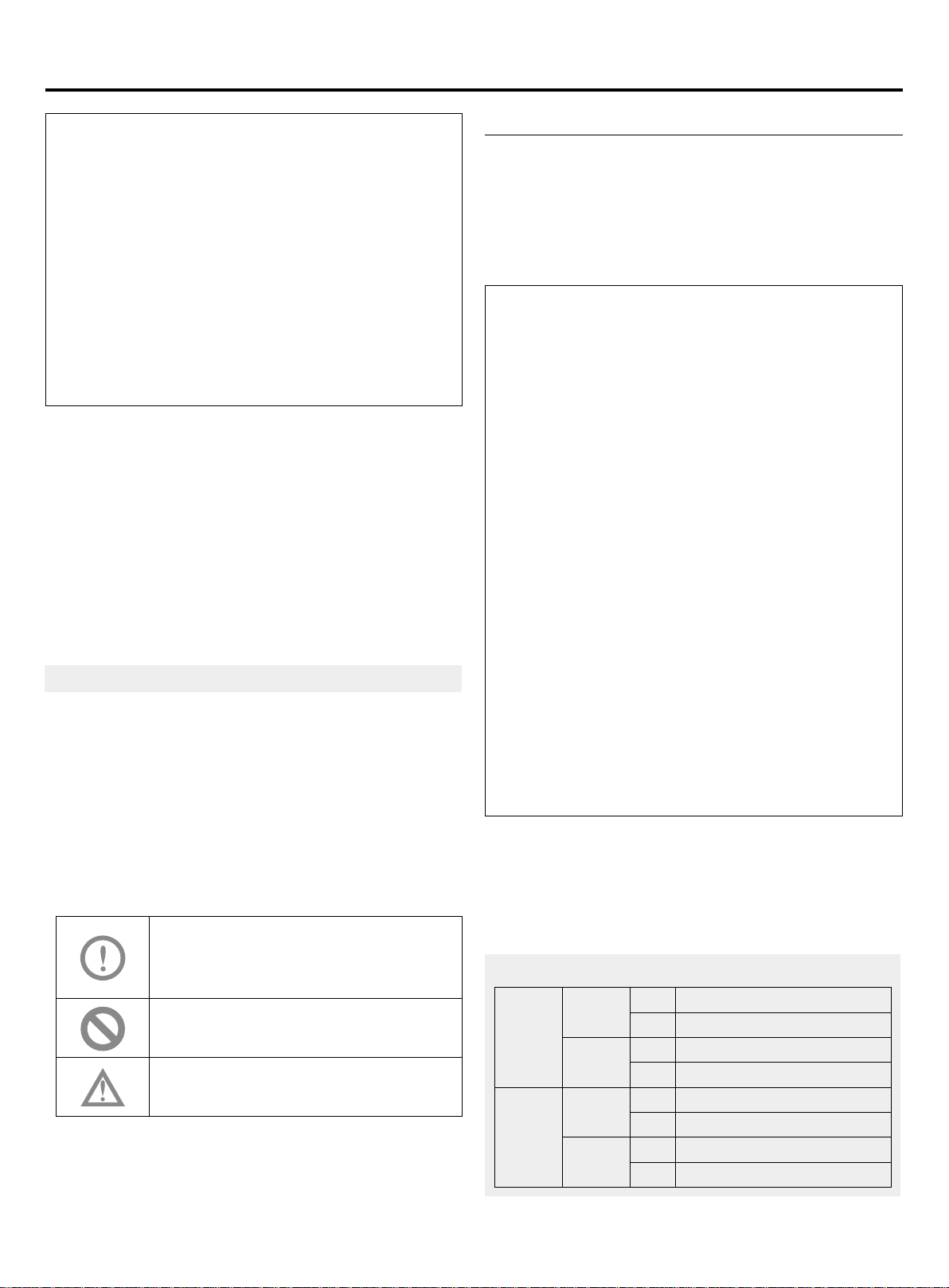
• Bold text (warning, prohibition, attention) used to indicate
the degree of risk. The following is a descriptionof the
text and symbols in the explanatory notes:
WARNING:
Indicates a potentially hazardous situation
which, if not avoided, will result in death or
serious injury.
PROHIBIT:
Do not carry out the operation.
CAUTION:
Sometimes it can cause serious accidents.
• If you have any questions, please contact the dealer or
the service center designated by our company.
• Please install air conditioning in accordance with local
standards.
CE
All the products are in conformity with the following
European provision:
-Low voltage Directive
-Electomagnetic Compatibility
Warning
•If the supply cord is damaged, it must be replaced by
the manufacturer, its service agent or similarly qualied
persons in order to avoid a hazard.
his appliance is not intended for use by persons
•
T
(including children) with reduced physical, sensory
or mental capabilities, or lack of experience and
knowledge, unless they have been given supervision or
instruction concerning use of the appliance by a person
responsible for their safety.
•
hildren should be supervised to ensure that they do
C
not play with the appliance.
•This appliance can be used by children aged from 8
years and above and persons with reduced physical,
sensory or mental capabilities or lack of experience
and knowledge if they have been given supervision or
instruction concerning use of the appliance in a safe
way and understand the hazards involved. Children
shall not play with the appliance. Cleaning and user
maintenance shall not be made by children without
supervision.
•The appliances are not intended to be operated by
means of an external timer or separate remote-control
system.
•Keep the appliance and its cord out of reach of children
less than 8 years.
Operation condition:
To use the air conditioner normally, please perform as to
the below conditions.
Operating Range of Air Conditioner
Cooling
Indoor
dry
Outdoor
Indoor
Heating
Outdoor
Max. DB:32°C WB:23°C
Min. DB:18°C WB:14°C
Max. DB:50°C WB:26°C
Min. DB:-5°C
Max. DB:27°C
Min. DB:15°C
Max. DB:27°C WB:15°C
Min. DB:-20°C
Page 3
Product Features
• The outdoor uint adopts "simultaneous control" type, all indoors should be heating or cooling simultaneously.
• To protect compressor,before startup,the unit should be electried for 12 hours.If the unit is not used for a long time,
please cut o the power to save energy, or the unit will consume the power.
This manual describes the installation and installation of outdoor units. For the installation of the indoor machine, please
refer to the instruction manual of the indoor machine.
Please read the installation instructions carefully before installation, according to the instructions of the installation
construction.
Safety
• If the air conditioner is transferred to the others, this manual should be tranferred together.
• Before installation, please read "Safety precaution" carefully to conrm the correct installation.
• The mentioned precaustion includes " WARNING" and " CAUTION". The precausion caused death or heavy injury
for faulty installation will be listed in " WARNING". Even the cautions listed in " CAUTION" also may cause serious
accident. So both of them are related to the safety, and should be executed severely.
• After installation, perform a trial and conrm everything normal, then introduce the operation manual to the user.
Besides, put the manual to the user and ask them to preserve it carefully.
WARNING
• The installation or the maintenance should be performed by the authorized agency. Or the non-specialized operation will
cause water leakage, electric shock or re etc accidents.
• The installation should be executed as per the manual, or the faulty installation will cause water leakage, electric shock
or re etc accidents.
• Please install the unit at the space which can bear the weight. Or the unit will drop down to cause the human injury.
• The installation should defend against the typhoon, and the earthquake etc. Abnormal installation will cause the unit fall
down.
• Use the correct cable and make reliable earthing. Fix the terminal rmly and the loose connection will cause heating or
re etc accident.
• The wiring should be in shape and can not be raised. Be earthed rmly and can not be clipped by the electric box cover
or the other plate. The incorrect installation will cause heating or re.
• When setting or transferring the unit, there should not be other air into the refrigerant system except for R410A. The gas
mixture will cause the abnormal high pressure which will cause break or human injury etc accidents.
• When installation, please use the accessories with the unit or the special parts, or it will cause water leakage, electric
shock, re, refrigerant leakage etc accidents.
• Don't lead the water drainage pipe into the drainage groove with the poisonous gas, such as sulphur. Or the poisonous
gas will enter indoor.
• In installation or after installation, please conrm if there is refriegerant leakage, please take measures for ventilation.
The refrigerant will cause poisonous gas as meeting re.
• Don't install the unit at the place where there may be ammable gas leakage. In case the gas leaks and gather around
the unit, it will cause re.
• The drainage pipe should be installed as per the manual to conrm the uent drainage. Also take measures for heat
insulation against dew drop. Incorrect water pipe installation will cause water leakage even and make the things wet.
• For the liquid pipe and the gas pipe, take measures for heat insulation too. If there is no heat insulation, the dew drop
will wet the things.
PROHIBIT
• Th is system using R410A refrigerant, prohibit lling oxygen, acetylene or other ammable and toxic gases in the air or
test, because these gases are very dangerous and may cause explosion. It is recommended to use compressed air,
nitrogen or refrigerant for such tests.
• Indoor or outdoor machines are not allowed to water. All of these products are equipped with electrical components,
which may cause serious electric shock accidents.
• Do not touch or adjust the safety device in the indoor or outdoor machine. If touching or adjusting these devices can
cause serious accidents.
1
Page 4
Safety
• The maintenance cover plate of the indoor or outdoor machine is forbidden when the main circuit power supply is not
cut o.
• The leakage of refrigerant can cause the air to be thin and dicult to breathe. In case of refrigerant leakage, close the
main valve, extinguish any ame and contact the local distributor immediately.
• Please use ELB (leakage protector). If not used, an electric shock or re may occur when an accident occurs.
• The installation and Service Engineer shall ensure that the refrigerant leaks comply with local laws and regulations.
CAUTION
• Execute earthing for the unit. But the earthing wire can not be connected to the gas pipe, water pipe, lightening rod or
the telephone earthing wire. Improper earthing will cause electric shock.
• Don't install the unit at the place where leaks the ammable gas. Or it will cause re.
• Execute the water drainage pipe according to the manual, improper installation will cause water leakage to wet the
family things.
• The outdoor fan can not face to the ower or the other vegetable, or the blowing gas will make the ower dried up.
• Please ensure the maintenance room, if not, it will cause the maintenance person damaged.
• When installing the unit on the roof or the other high place, to prevent the person falling down, please set the xed
ladder and the railing at the passage.
• Use the two-end spanner, and fasten the nut at proper torque. Don't fasten the nut excessively against the ared setion
broken. Or it will cause refrigerant leakage and lack of oxygen.
• Take measures for heat insulation to the refrigerant pipe, or there will be water leakage or dew drop to wet the family
things.
• After nishing the refrigerant pipe, make leakage test by charging the nitrogen. In case the refrigerant leaks in a small
room and exceeds the limited concentration, it will cause lack of oxygen.
• Don't use the other refrigerant except for R410A. The R410A pressure is 1.6 times higher than R22 pressure. The
refrigerant R410A tank is marked with pink sign.
• Against charging dierent refrigerant, we changed the stop valve diameter of the R410A unit. To enhance the
compression consistance, we also changed the ared pipe dimension. Prepare the R410A specially tools according to
the below table.
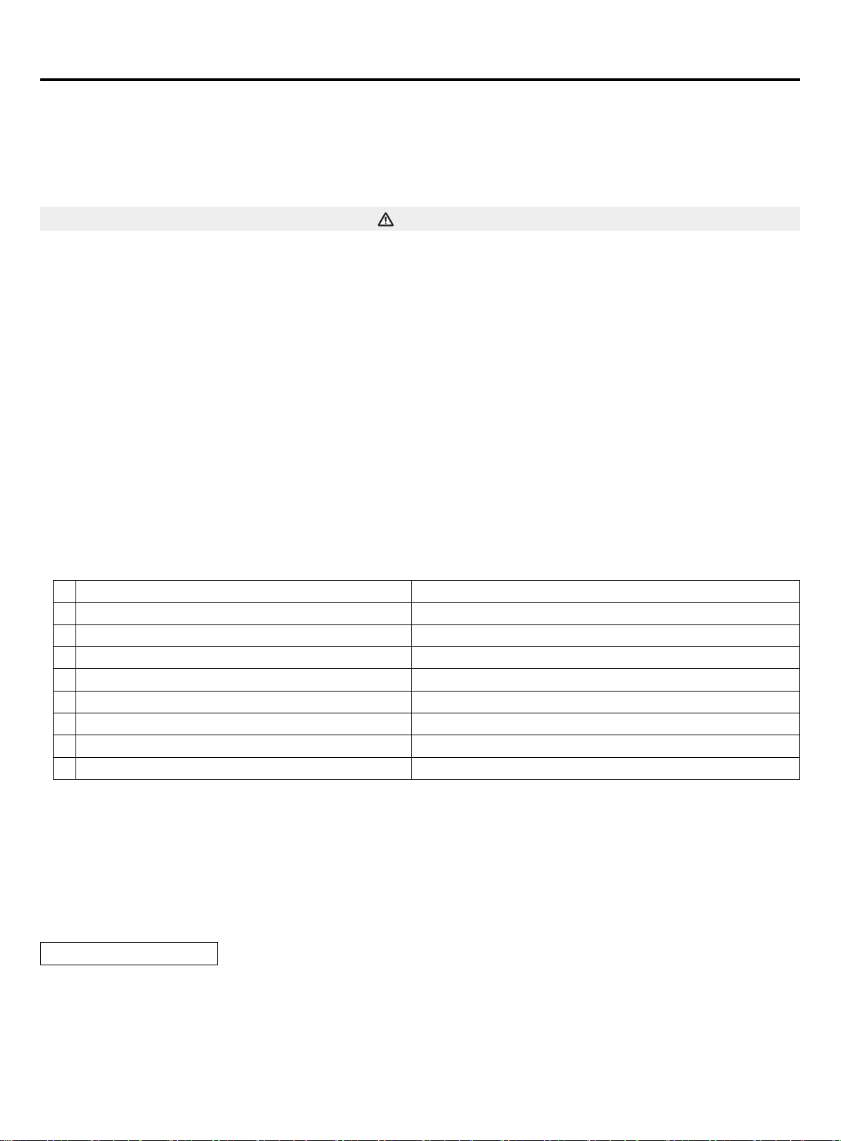
R-410A specied tools Remarks
1 Gauge manifold Range: HP
2 Charge hose Pressure: HP: 5.3MPa, LP: 3.5MPa
3 Electronic balance for charging R410A Can not use the measurable charging tank
4 Torque spanner
5 Flare tool
6 Copper pipe gauge for adjusting projecting margin
7 Vacuum pump adapter Must be with reverse stop valve
8 Leakage detector Can not use freon leakage detector, but the He detector
>
4.5MPa, LP>2MPa
• When charging refrigerant, the refrigerant must be taken out as liquid state from the tank.
• When installing the power cord and the connecting line must be at least 1m from the TV or radio, so as to avoid image
interference or noise.
• In the room with uorescent lamp (reverse or fast start type), remote control signal transmission distance may not reach
the predetermined value, so the indoor machine installed away from the uorescent lamp as far as possible.
• Please use the fuse to meet the capacity requirements.
• To prevent the destruction of wires, electrical components, etc. by rats or other animals.
• Recommended room ventilation every 3 to 4 hours.
Arrival inspection
• After receiving the machine, should check whether there is transport damage. If any damage is found on the
surface or inside, it shall be reported immediately to the shipping company in writing.
• Check the product model, electrical parameters (power supply, voltage, frequency) and accessories to
determine whether they meet the requirements.
2
Page 5
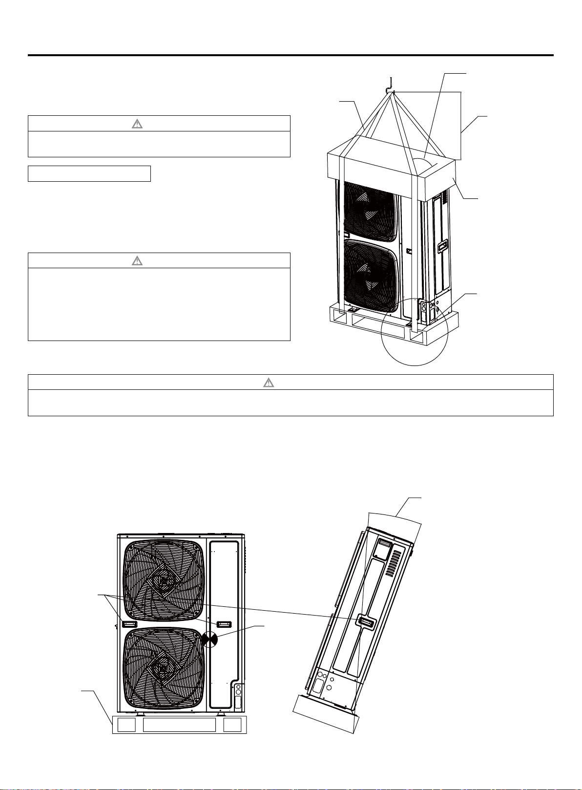
Transportation and Lifting
Lifting
In front of the unit shipped from unpacking location as close
as possible.
CAUTION
Do not place anything on the device.
•
Two ropes shall be used for lifting the outdoor unit.
•
Hoisting method
Hoisting to ensure that the level of outdoor machine, slowly
lifting.
1. Removal of outer packing is strictly prohibited
2. As shown by two ropes hoist with outdoor machine
packaging.
CAUTION
In order to ensure safety, maintain the level of lifting,
•
slowly lifting.
Do not lift the elevator to the packing and outer packing
•
of the equipment.
External protection should be used when lifting, such as
•
cloth or cardboard.
Over 60 degrees
rope
0.7~1.0 meters
Do not remove
packing tape and
packing box.
As shown in the
rope through
the wood base
around the lifting
hole.
Manual handling
CAUTION
In the installation and commissioning, the outdoor machine do not put any irrelevant material, to ensure that there is
•
no debris inside the machine, or there may be a fire or accident.
Pay attention to the following points when handling the equipment manually:
1. No demolition wood base.
2. In order to prevent the dumping of the outdoor machine, the center of gravity of the unit should be noted as shown in
the gure.
3. Two or more people to carry out the outdoor machine.
This product maximum tilt
angle 20 degrees.
Handle hole
Focus
Wood base
3
Page 6
Installation instruction
In installation, please check specially the below items:
• If the connected units quantity and the total capacity is in the allowable range?
• If the refrigerant pipe length is in the limited range?
• If the pipe size is proper? And if the pipe is installed horizontally?
• If the branch pipe is installed horinzontally or vertically?
• If the additional refrigerant is counted correctly and weighed by the standard balance?
• If there is refrigerant leakage?
• If all the indoor power supplies can be on/o simultaneously?
• If the power voltage is in compliance with the data marked on the rating label?
• If the address of indoors has been set?
(1) Before installation
1) Before installation, check if the model, power supply, pipe, wires and parts purchased respectively are correct.
2) Check if the indoors and outdoors can be combined as the following.
Outdoor Indoor
Capacity
(100w)
80 Single 4 40-104
140 Single 8 70-182
180 Single 9 90-234
Notice:
• Total capacities of indoor units being used ≤ 100% of rated
capacities of outdoor unit.
• The maximum number and total capacity of indoor units are
shown in the table above.If the total capacity of the indoor units is greater than the rated capacity of the outdoor unit, the
actual cooling or heating eect of each indoor units may not reach its rated capacity.
Combination
type
Indoor qty
Total indoor capacity
(100w)
indoor capacity
(100W)
22
28
36
40
45
56
71
total indoor
capacity
(100W)
less than 335 FQG-B335A
branch pipe
(optional)
(2) Installation place selection
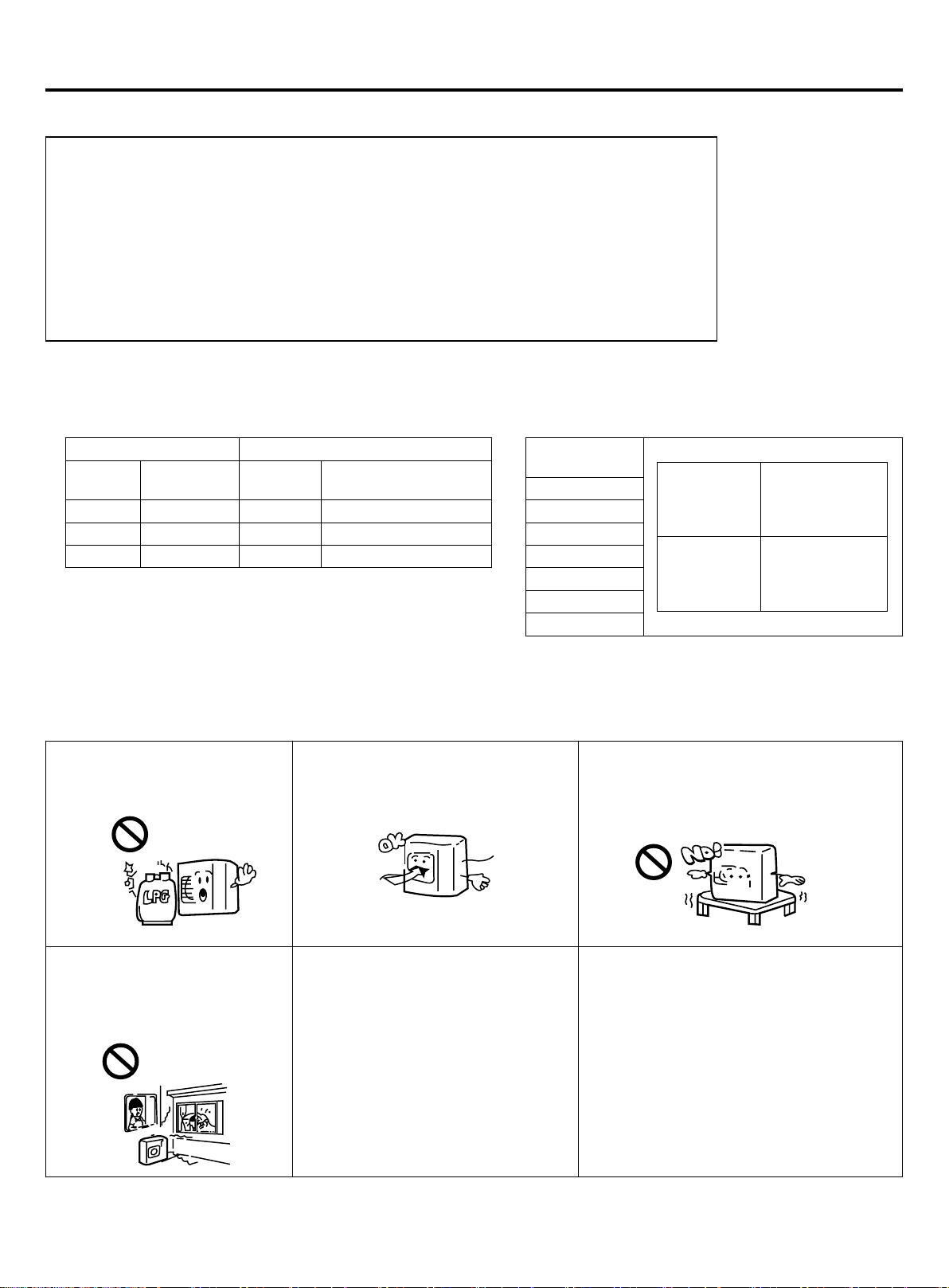
Air-conditioner can't be installed
in the place with inammable
gas. Or it will cause re hazard.
The unit should be installed at
the place where the cold/hot
air or noise will not interfere the
neighbours.
The unit should be installed at the
place with good ventilation. No
obstacle at the air inlet/outlet. And no
strong wind blows the unit.
The installation space refers to the
latter info.
• The place where the water can ow
uently.
• The place where no other heat
source will aect the unit.
• Pay attention to the snow against
clogging the outdoor.
• In installation, install the antivibration rubber between the unit
and the bracket.
The unit should be installed at the strong
enough place. Or it will cause vibration and
noise.
• The unit is better not be installed at the
below places, or it will cause damage.
• The place where there is corrosive gas
(spa area etc).
• The place blowing salty air (seaside etc).
• Exsits the strong coal smoke.
• The place with high humidity.
• The place where there is device emitting
Hertzian waves.
• The place where voltage changes greatly.
4
Page 7
Installation instruction
Note:
1. In snowy area, install the unit under the bracket or the snow-proof cover against the accumulative snow on the unit.
2. Do not install the unit at the place where the ammable gas will leak.
3. Install the unit at the strong enough place.
4. Install the unit at the at place.
5. When being installed at the place with strong wind, set the air outlet of the unit and the wind direction vertical.
6. The installation site should be far away from the place where the noise is higher. At the same time for the noise of
higher places should ensure that the outdoor machine vibration and wall insulation measures to prevent vibration
caused by thin wall or acoustic noise problems.
7. Aluminum foil n is very sharp, pay attention to prevent scratches.
8. In addition to the maintenance of the roof, or the installation of outdoor machines, other people can not contact the
outdoor machine.
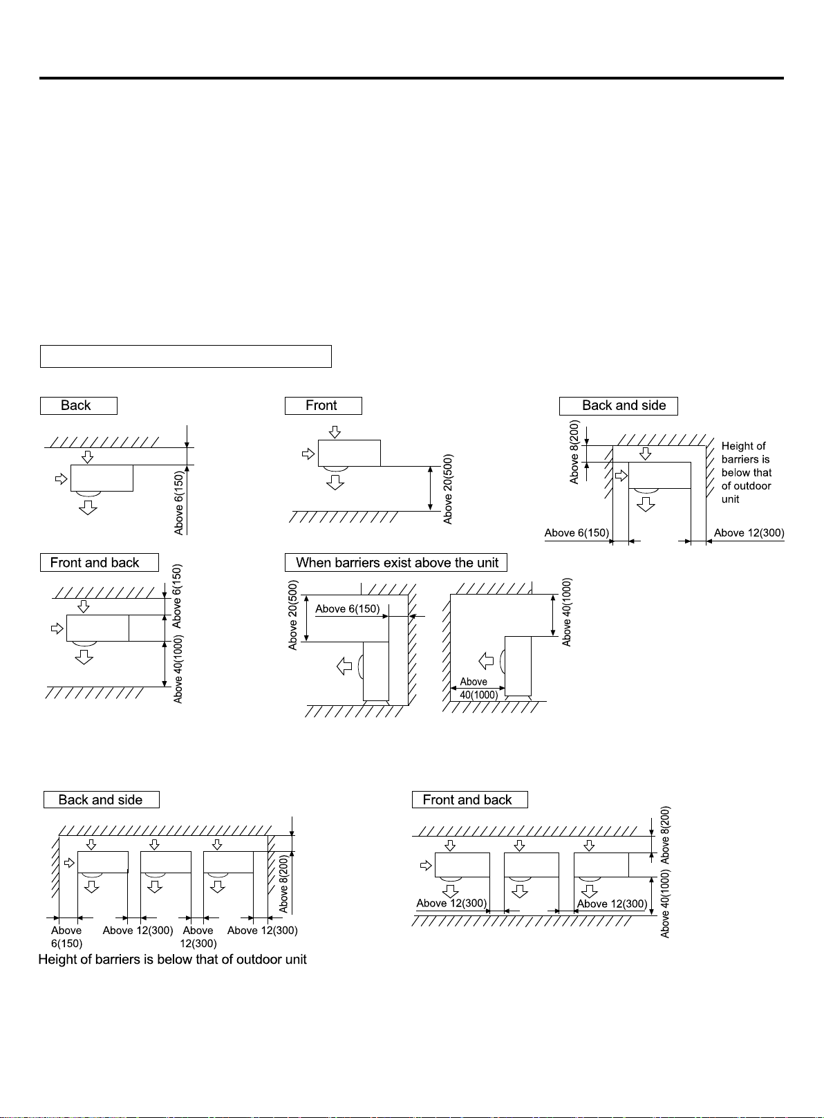
(3) Installation and maintenance space
Selection of installation location of outdoor
(1) Single-unit installation (unit: in.(mm))
The top and two side surfaces must be exposed to open space, and barriers on at least one side of the front and back
shall be lower than the outdoor unit.
(2) Multi-unit installation (unit: in.(mm))
5
Page 8
Installation instruction
(3) Multi-unit installation in front and back (unit: in.(mm))
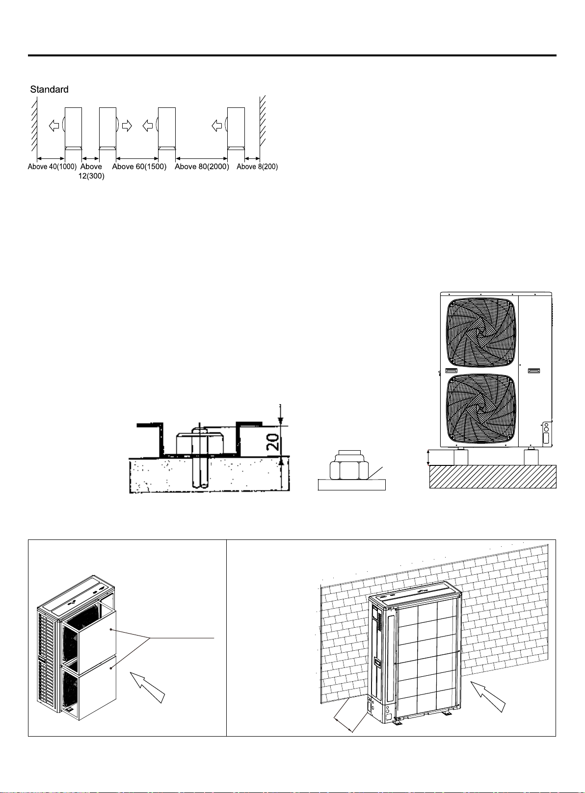
The top and two side surfaces must be exposed to open
space, and barriers on at least one side of the front and back
shall be lower than the outdoor unit.
• The installation service spaces shown in the illustrations are based on an air intake temperature of 95°F(35°C)(DB)
for COOL operation. In regions where the air intake temperature regularly exceeds 95°F(35°C)(DB), or if the heat load
of outdoor units is expected to regularly exceed the maximum operating capacity, reserve a larger space than that
indicated at the air intake side of units.
• Regarding the required air outlet space, position the units with consideration to the space required for the onsite
refrigerant piping work as well. Consult your dealer if the work conditions do not match those in the drawings.
(4) Precautions on installation
NOTICE
If drain holes of the outdoor unit are covered by a mounting base or by oor surface, raise
the unit in order to provide a free space of more than 5in.(130mm) under the outdoor unit.
Foundation work
• Check the strength and level of the installation ground so that the unit will not cause any
operating vibration or noise after installation.
• In accordance with the foundation drawing in the gure, x the unit securely by means of
the foundation bolts.
• It is best to screw in the foundation bolts until their length are 0.8in.(20mm) from the
foundation surface.
1
˃5in.(130mm)
• Fix the outdoor unit to the foundation bolts using nuts with resin washers(1) as shown in the gure.
• If there is no need to install the outdoor machine in the open space of the building or the enclosure, the following two
ways can be used to avoid the fan reversal or damage caused by strong wind blowing.
(1) Using the windshield
Wind deector
Fierce wind
(2) Near wall installation
More than 2000mm
Fierce wind
6
Page 9
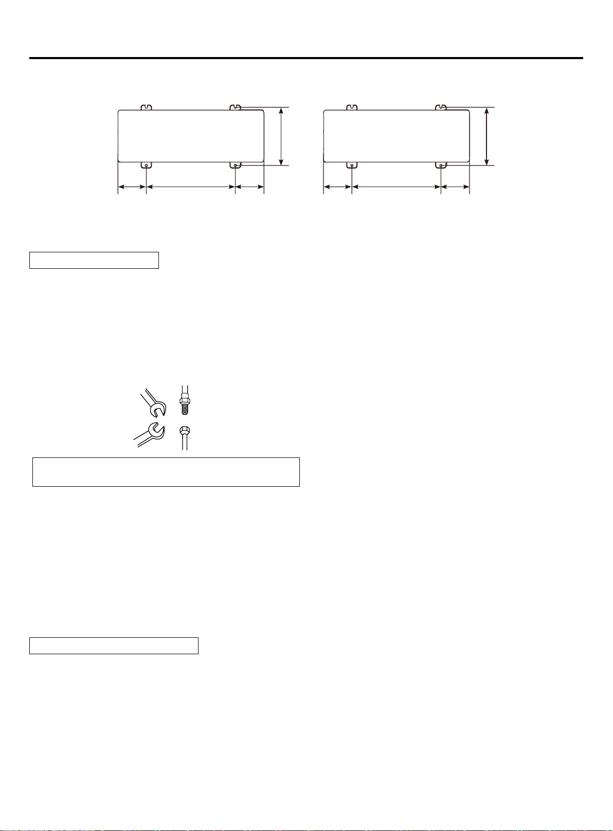
Installation instruction
If the coating on the fastening area is stripped o, the nuts rust easily.
Dimensions (bottom view) (unit of measurement: mm)
402
130
661
AU032FSEUA AU052FPEUA
154
175
600
AU072FPEUA
175
405
(5) Refrigerant pipe connection
Pipe connection method:
• To ensure the eciency, the pipe should be as short as possible.
• Daub the refrigerant oil on the connector and the are nut.
• When bending the pipe, the bending semi-diameter should be as large as possible against the pipe being broken or
bent.
• When connecting the pipe, aim at the center to thread the nut by hand and tighten it with the double spanners.
• Don't let the impurity such as sand, water etc into the pipe.
When fastening and loosing the nut, operate with double
spanners, because only one spanner cannot execute rmly.
Spanner
Connector
Nut
Spanner
If threading the nut as not aiming at the center, the screw
thread will be damaged, further it will cause leakage.
Cautions in piping installation:
• When welding the connector with hard solder, charge nitrogen into the pipe against oxidation. Or the oxygen lm in the
pipe will clog the capillary and the expansion valve, even caue the deathy accident.
• The refrigerant pipe should be clean. If the water and the other impurity enter the pipe, charge the nitrogen to clean the
pipe. The nitrogen should ow under the pressure of about 0.5Mpa and when charging the nitrogen, stop up the end of
the pipe by hand to enhance the pressure in the pipe, then loose the hand (meanwhile stop up the other end).
• The piping installation should be executed after the stop valves are closed.
• Before welding the valve and the pipes, use the wet cloth to cool down the valve and the pipes.
• When the connection pipe and the branch pipe need to be cut down, please use the special shears and cannot use the
saw.
Pipe material and specs selection
1. Please select the refrigerant pipe of the below material.
Material: the phosphoric oxidize seamless copper pipe, model: C1220T-1/2H (diameter is over 19.05); C1220T-0
(diameter is below 15.88).
2. Thickness and specs:
Conrm the pipe thickness and specs according to the pipe selection method(the unit is with R410A, if the pipe over
19.05 is 0-type, the pressure preservation will be bad, thus it must be 1/2H type and over the min. thickness.
3. The branch pipe must be from Haier.
4. When installing the stop valve, refer to the relative operation instruction.
5. The pipe installation should be in the allowable range.
6. The installation of branch pipe and gather pipe should be performed according to the relative manual.
7
Page 10
Installation instruction
Drain pipe disposal
• Make sure the drain works properly.
• In regions where buildups of snow can be expected, the accumulation and freezing of snow in the space between the
heat exchanger and external plate may lower operating eciency.
• After punching the knock-out hole, the application of repair-type paint on the surface around the edge sections is
recommended to prevent rust.
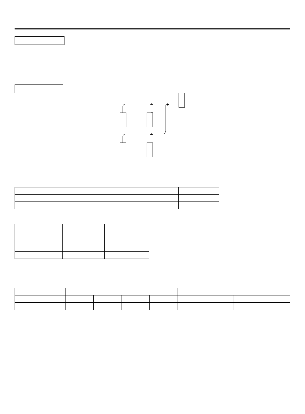
Pipe specication:
b
c
a
a
b
a
1. Pipe "a" diameter (between indoor and branch pipe) (depends on indoor pipe)
Please refer to the indoor air conditioner manual.
2. Pipe "b" diameter (between branch pipes)
Total indoor capacity after the branch pipe (x100W) Gas pipe (mm) Liquid pipe (mm)
X<112 Ø15.88 Ø9.52
112≤X< 234 Ø19.05 Ø9.52
3. Pipe "c" diameter ( outdoor pipe diameter)
Outdoor capacity
(100W)
80 Ø15.88 Ø9.52
140 Ø19.05 Ø9.52
180 Ø19.05 Ø9.52
Note:
When the distance from outdoor to the longest indoor is over 30m, the main pipe should be the enlarged diameter.
Copper pipe selection:
hardness softness Half-hardness
Outer diameter (mm) Ø6.35 Ø9.52 Ø12.7 Ø15.88 Ø19.05 Ø22.22 Ø25.24 Ø28.58
Min. thickness (mm) 0.8 0.8 1.0 1.0 1.0 1.1 1.2 1.4
Note:
If the copper pipe with outer diameter 19.05 is coil pipe, the thickness should be over 1.1.
Gas pipe (mm) Liquid pipe (mm)
a
8
Page 11
Installation instruction
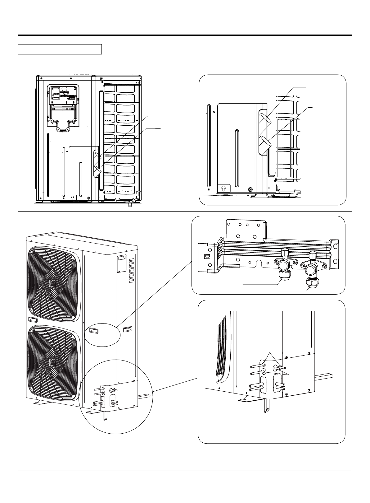
Piping connection method:
Outdoor uint with single fan piping connection method
Enlarged diagram
gas pipes
liquid pipes
gas pipes
liquid pipes
Outdoor uint with double fan piping connection method
Pipes can be connected in four directions
liquid pipes
Enlarged diagram
F
A
gas pipes
E
B
C
D
A, B, C, D:Copper pipe hole
E:Power cord hole (with its own cable sheath)
As shown in the gure, the piping can be connected from four
directions. Through the front / rear hole piping piping on the cover hole or crack directly across the oor.
From the outdoor machine unloading piping cover with a screwdriver and hammer knock o holes along the guide wire
break. Then, trim the edges of the holes, and mounted on the insulating sleeve (site) to protect the piping and wiring.
9
F:Communication line hole
Page 12
Installation instruction
Long pipe and high drop
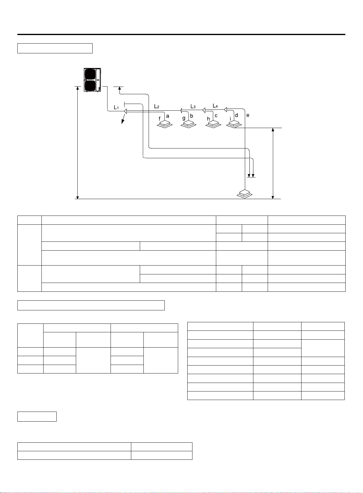
1. Allowable pipe length and height dierence
Outdoor unit
First branch piping
Length of the longest piping L
Length of the longest piping after the
rst branch piping L (*)
Drop height between indoor and outdoor units
Maximal length and drop height permissible of refrigerant piping
Total length of piping (actual length)
Piping
length
Drop
height
Piping length of indoor unit which is furthest to the rst branch
Drop height between indoor and
Longest piping L Actual / Equivalent length 60/70m L1+L2+L3+L4+e
piping L (*)
Up outdoor 50m ——
outdoor unit H
Drop height between indoor units h 10m ——
Under outdoor 40m ——
Indoor unit
h≤10m
indoor units
Drop height between
Permissible value Piping part
80 120m L1+L2+L3+L4+a+b+c+d+e
140/180 150m
40m L2+L3+L4+e
Unit pipe spec and connection method (unit: mm)
A. Outdoor unit
Gas pipe side Liquid pipe side
Model
AU03 Ø15.88
AU07 Ø19.05 Ø9.52
B. Indoor unit
Please refer to the indoor air conditioner manul.
Connecting method: Flared joint
Branch pipe
Outdoor unit type
Branch pipe selection:
Diameter
(mm)
Total indoor capacity (100W) Model (optional)
Less than 335 FQG-B335A
Connecting
method
Flared joint
Diameter
(mm)
Ø9.52
Connecting
method
Flared jointAU05 Ø19.05 Ø9.52
C. Pipe spec and the torque
Diameter (mm) Thickness (mm) Torque (N.m)
Ø6.35 0.8 16~20
Ø9.52 0.8
Ø12.7 1.0
Ø15.88 1.0 90~120
Ø19.05 1.0 100~140
Ø22.22 1.1 ——
Ø25.4 1.2 ——
Not less than Ø28.58 More than 1.4 ——
Note: If the copper pipe with outer diameter 19.05 is coil
pipe, the thickness should be over 1.1.
10
40~50
Page 13
Installation instruction
Note:
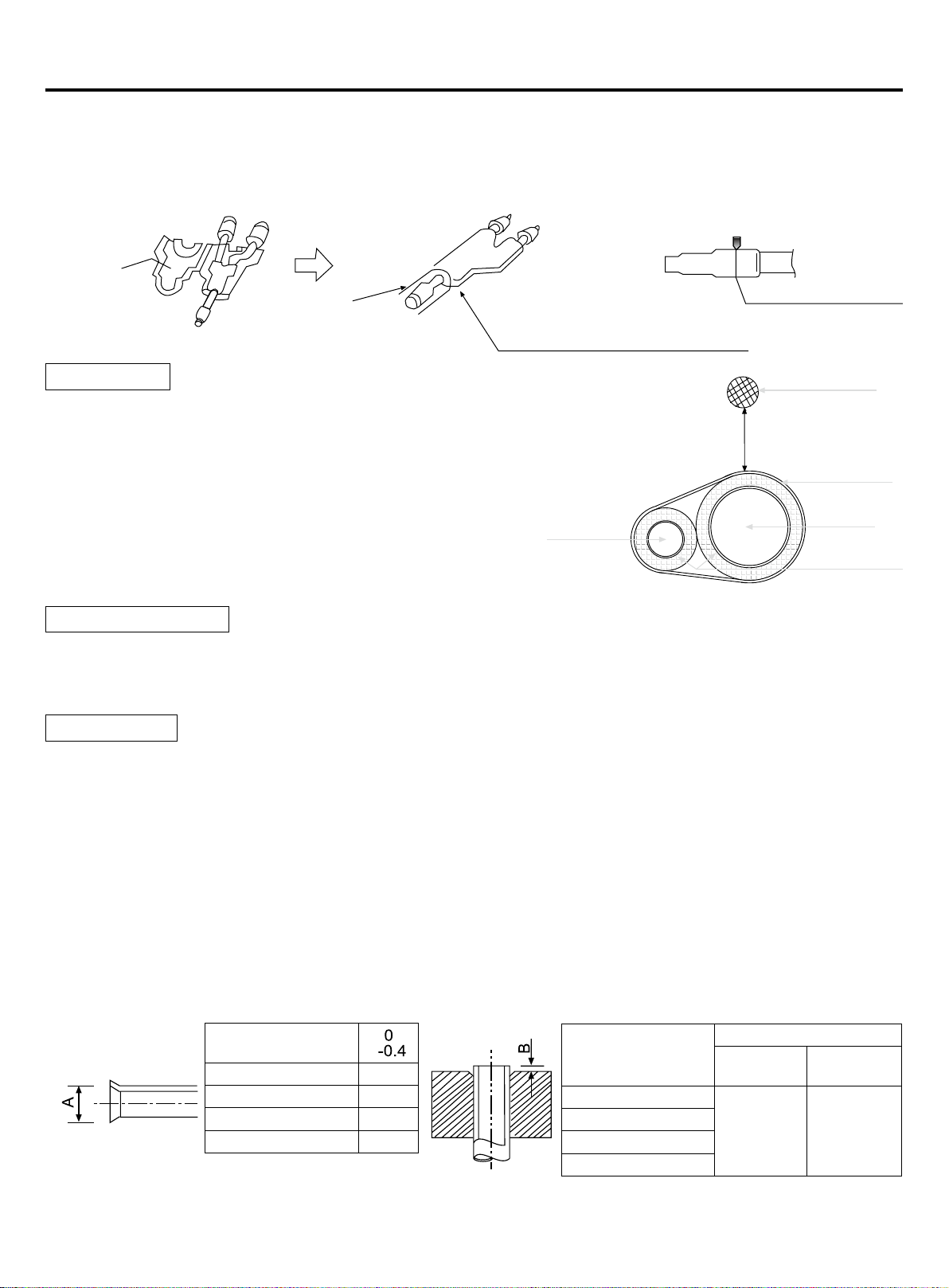
1. When connecting the pipe and the outdoor, please pay attention to the outdoor pipe dimension.
2. When adjusting the diameter among pipes and among the units, please must execute at the branch pipe side.
3. When welding with hard solder, please must blow nitrogen. If not, a number of oxide will be produced and cause heavy
damage.Besides,to prevent water and dust into the pipe, please make the brim as outer roll.
Cut o pipe with the cutter
Adhesive side
Prepare on eld
Heat insulation
• Gas pipe and liquid pipe should be heat insulated separately.
• The material for gas pipe should endure the high temperature
over 120°C.That for liquid pipe should be over 70°C.
• The material thickness should be over 10mm, when ambient
temp. is 30°C, and the relative humidity is over 80%, the material
thickness should be over 15mm.
• He material should cling the pipe closely without gap, then be
wrapped with adhesive tape. The connection wire can not be put
together with the heat insulation material and should be far at
least 20cm.
Fix the refrigerant pipe
• In operation, the pipe will vibrate and expand or shrink. If not being xed, the refrigerant will focus on one part to cause
the broken pipe.
• To prevent the central stress, x the pipe for every 2-3m.
Pipe installation
Seal the connection and wrap the
heat insulator with adhesive tape
Liquid pipe
Cut o at the middle
Connection wire
over 20cm
Adhesive tape
Gas pipe
Heat insulator
When doing the piping connection, please do the following:
• Please don't let the pipe and the parts in the unit collide each other.
• When connecting the pipes, close the valves fully.
• Protect the pipe end against and water, impurities (welding after being atted, or being sealed with adhesive tape).
• Bend the pipe as large semi-diameter as possible(over 4 times of the pipe diameter).
• The connection between outdoor liquid pipe and the distributing pipe is ared type. Please expand the pipe with the
special tool for R410A after installing the expanding nut. But if the projecting pipe length has been adjusted with the
copper pipe gauge, you can use the original tool to expand the pipe.
• Since the unit is with R410A, the expanding oil is ester oil, not the mineral oil.
• When doing the are connection, please do the following: When connecting the expanding pipe, fasten the pipes with
double-spanner. The torque refers to the former info.
Expanding pipe: A(mm)
Pipe outer diameter
(mm)
Ø6.35 9.1
Ø9.52 13.2
Ø12.7 16.6
Ø15.88 19.7
• The outdoor gas pipe and the refrigerant distributing pipe, as well the refrigerant distributing pipe and the branch pipe
should be welded with hard solder.
A
11
Projecting length of pipe to be expanded: B(mm)
Pipe outer diameter
(mm)
Ø6.35
Ø9.52
Ø12.7
Ø15.88
When it is hard pipe
Special tool
for R410A
0-0.5 1.0-1.5
The former
tool
Page 14
Installation instruction
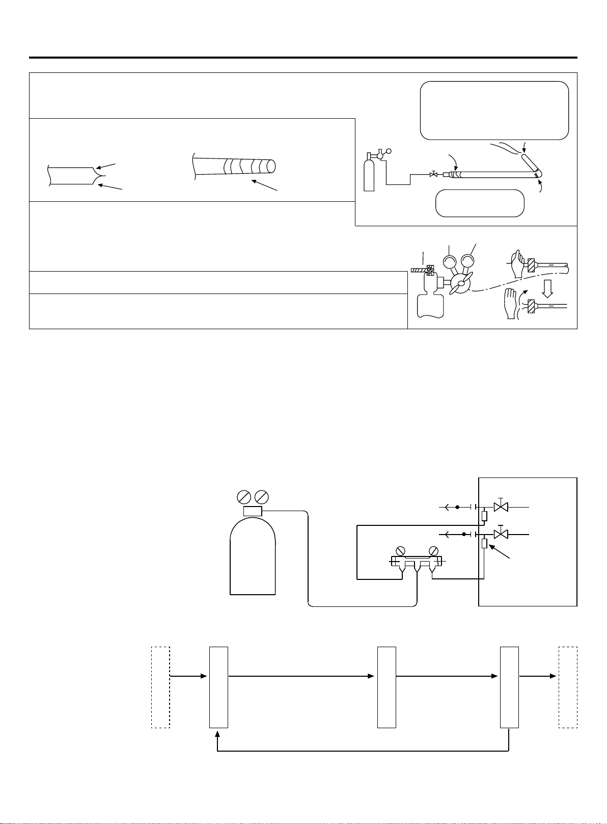
• Weld the pipe at the same time charge the nitrogen. Or it will cause a number
of impurity (a lm of oxidation) to clog the capillary and the expansion valve,
further cause the deadly failure.
• Protect the pipe end against the water, impurity into the pipes
(welding after being at, or being sealed with adhesive tape).
Flat
Brazing
• The refrigerant pipe should be clean. The nitrogen should ow under
the pressure of about 0.2Mpa and when charging the nitrogen, stop
up the end of the pipe by hand to enhance the pressure in the pipe,
then loose the hand (meanwhile stop up the other end).
• When connecting the pipes, close the valves fully.
• When welding the valve and the pipes, use the wet cloth to cool down the
valve and the pipes.
Adhesive tape
Source valve
Seal the pipe end with
adhesive tape or the stopper
to increase the resistance, ll
up the pipe with nitrogen.
Taping
1st side
<N2>
Only nitrogen gas
can be used
2nd side
0.2MPa
Hand
Brazing
(6) Leakage test
1. The outdoor unit has been executed the leakage test in the factory. After connecting the distributing pipe, execute the
leakage test from the outdoor check valve and the indoor. Besides, while testing, the valves should be close.
2. Refer to the below gure to charge the nitrogen into the unit to take a test. Never use the chlorin, oxygen, ammable
gas in the leakage test. Apply pressure both on the gas pipe and the liquid pipe.
3. Apply the pressure step by step to the target pressure.
a. Apply the pressure to 0.5MPa for more than 5 minutes, conrm if pressure goes down.
b. Apply the pressure to 1.5MPa for more than 5 minutes, conrm if pressure goes down.
c. Apply the pressure to the target pressure (4.0MPa), record the temp. and the pressure.
d. Leave it at 4.0MPa for over 1 day, if pressure does not go down, the test is passed. Meanwhile, when the temp.
changes for 1degree, pressure will
change 0.01MPa as well. Correct the
p r e s s u r e .
e. After conrmation of a~d, if pressure
goes down, there is leakage. Check
the brazing position, ared position by
laying on the soap. modify the leakage
point and take another leakage test.
4. After leakage test, must execute the
evacuation.
Nitrogen
To indoor
Gauge manifold
Lo
Lo handle
Hi
Hi handle
Check valve
Gas pipe
Gas pipe
Check hole
(7) Evacuation
Evacute at the check valve of liquid stop valve and both sides of the gas stop valve.
Operation procedure:
After reaching -101KPa or
less (below -755mmHg), let
the vacuum pump running
Leakage test passed
Evacuation begins
continuously for over 1hour.
If vacuum pointer arises, it shows there is water or leakage in the
system, please check and modify it, and then evacuate again.
12
Leave it for over 1
hour, vacuum pointer
does not arise.
Evacuation ends
Outdoor
Check vacuum
Charge refrigerant
Page 15
Installation instruction
Because the unit is with refrigerant R410A, the below issues should be paid attention:
• To prevent the dierent oil into the pipe, please use the special tool for R410A, especially for gauge manifold and
charging hose.
• To prevent the compressor oil into the refrigerant cycle, please use the anti-counter-ow adapter.
(8) Check vale operation
Open/close method:
• Take down the valve cap.
• Turn the liquid stop valve and the gas stop valve with hexangular spanner until it stops. If opening the valve strongly,
the valve will be damaged.
• Tighten the valve cap.
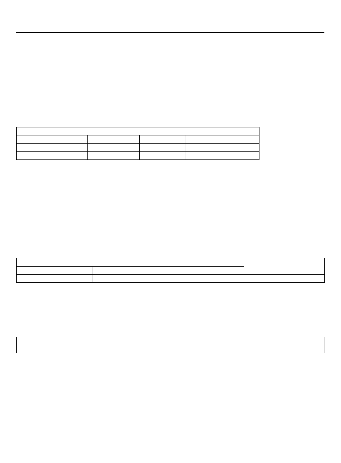
Tighten torque as the table below:
Tighten torque N.m
Shaft (valve body) Cap (cover) T-shape nut (check joint)
For gas pipe Less than 7 Less than 30 13
For liquid pipe 7.85 (MAX15.7) 29.4 (MAX39.2) 8.8 (MAX14.7)
(9) Additional refrigerant charging
Charge the additional refrigerant as liquid state with the gauge.
If the additional refrigerant can not be charged totally when the outdoor stops, charge it at the trial mode.
If the unit runs for a long period in the state of lack of refrigerant, compressor will occur failure.
(the charging must be nished within 30 minutes especially when the unit is running, menawhile charging the refrigerant).
A. Charging amount when out of factory excludes the refrigerant in the pipe.
B. The unit only is charged the standard volume of refrigerant (distributing pipe length is 0m). Additional charging
amount=actual length of liquid pipe x additional amount per meter liquid pipe
Additional charging amount=L1×0.35+L2×0.25+L3×0.17+L4×0.11+L5×0.054+L6×0.022
L1: total length of 22.22 liquid pipe; L2: total length of 19.05 liquid pipe; L3: total length of 15.88 liquid pipe;
L4: total length of 12.7 liquid pipe; L5: total length of 9.52 liquid pipe; L6:total length of 6.35 liquid pipe;
C. Refrigerant charging and additional charging
Additonal refrigerant charging per meter(kg/m)
Ø22.22 Ø19.05 Ø15.88 Ø12.7 Ø9.52 Ø6.35
0.35 0.25 0.17 0.11 0.054 0.022 Refer to label
Charge when out of factory
Note:
• To prevent the dierent oil into the pipe, please use the special tool for R410A, especially for gauge manifold and
charging hose.
• Mark the refrigerant type in dierent colour on the tank. R410A is pink.
• Must not use the charging cylinder, because the R410A will change when transferring to the cylinder.
• When charging refrigerant, the refrigerant should be taken out from the tank as liquid state.
• Mark the counted refrigerant volume due to the distributing pipe length on the label.
GWP: 2088
The product contains uorinated greenhouse gases and its functioning relies upon such gases.
(10) Refrigerant recovery
• Start: press the main control board of the Start and Stop keys at the same time for 5 seconds, the machine enters
the refrigerant automatic recovery control: the compressor starts, the right side of the machine C0 and Ps digital tube
ashing, lasted for about 3 minutes.
• Operation: when the digital tube C1 and Ps alternately ashing, manually shut o the liquid pipe valve, the refrigerant
recovery.
• O valve: when Ps < 1kg, digital tube display C2, fast manual shut-o valve, 5S after the system shut down.
• End: manual power down for program reset.
Note: heating, standby or shutdown: outdoor machine forced to refrigeration operation.
13
Page 16
Electric wiring and the application
WARNING
• Switch o the main power switch of the indoor
and outdoor machine for more than 1 minutes
before the wiring or regular inspection.
• To prevent the destruction of wires and
electrical components by rats or other animals.
Serious, it may lead to the occurrence of re.
• To avoid damage to the wire, avoid contact with
refrigerant pipes, steel edges and electrical
components. Serious, it may lead to the
occurrence of re.
CAUTION
• Secure the power cord with a wire tie in the
machine.
Note:
when the wiring of the outdoor machine is not
using the wire, it should be xed with the rubber
ring.
CAUTION
• In the case of 3 phase 5 wire type, the
power supply of the indoor machine must be
connected use L1 line and N line, prohibit the
use of L1-L2, L1-L3, Otherwise the electrical
part will be damaged.
Inspect
• To ensure that the electrical equipment used on the installation
site (main power switch, circuit breaker, wire, conduit and wiring
terminals, etc.) have been selected according to current data, to
ensure that the device in line with national standards.
• Check the power supply voltage in the range of 10% of the rated
voltage and the ground wire is included in the power supply line.
Otherwise, electrical parts will be damaged.
• Check whether the power supply is satised. Otherwise, the
compressor will not start when the voltage is too low.
• By measuring the insulation resistance between the ground
and the electrical device terminals, to ensure that more than 1
MΩ. Otherwise, the system can not be started until the cause of
leakage and maintenance.
Connection
• Connect the power cord to the terminal of the indoor unit and the
outdoor mechanical and electrical gas box, connect the ground
wire to the grounding bolt of the outdoor machine and the indoor
mechanical and electrical air box.
• Connect the external and internal communication lines to the
1 and the 2 terminals on the terminal. If the power cord is
connected, the printed circuit board will be damaged. And the use
of shielded twisted pair wire.
• Do not connect the fastening screws on the front of the cover.
• The power cord must be made of copper wire, and the power
supply must be in line with IEC 60245 requirements. If the power
cord length exceeds 20m, the need to increase the size.
• The power supply line is xed with a round connection terminal
with an insulating protective sleeve. Not with sheet metal contact
and extrusion, in order to avoid the cut line of skin caused by re.
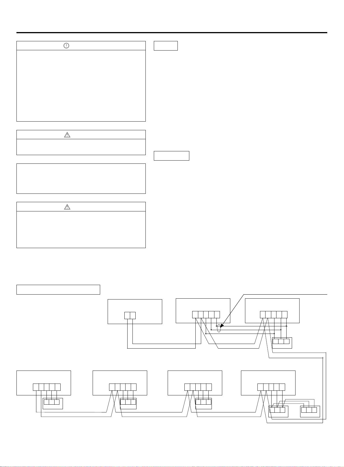
Communication wiring gure
Outdoor
PQ
Indoor 1
PQ A B C
Communication wire with polarity
Indoor 2
*
Indoor 3 Indoor 4 Indoor 5 Indoor 6
PQ A B C PQ A B C PQ A B C
A B C
wired
controller
A B C
wired
controller
14
A B C
wired
controller
PQ A B C
A B C
PQ A B C
A B C
wired
controller
wired
controller
A B C
wired
controller
Page 17
Electric wiring and the application
The outdoor and all indoor units are in parallel through 2 non-polar wires.
Three wiring methods between wired controller and indoor unit:
A. 1 to multi (group control): one wired controller controls 2~16 indoors, as shown in above gure, indoor 1~indoor 2:
indoor 2 is wired control master unit, the others are wired control slave units. Wired controller and the master indoor
(directly connected to wired controller) is connected by 3 polar wires; the other indoors and the master indoors are
connected by 2 or 3 polar wires, AC indoors wired "B" "C" polar wires, DC indoors wired "A" "B" "C" polar wires*.
B. 1 to 1 (one wired controller controls one indoor): as shown in above gure, indoor 3~ indoor 4, indoor and wired
controller are connected by 3 polar wires.
C. 2 to 1 (two wired controller controls one indoor): as shown in above gure, indoor 6. Either of wired controllers can be
set as master wired controller, and the other is slave wired controller. Master/slave wired controller, and master/indoor
are connected by 3 polar wires.
When indoor is controlled by remote controller, refer to the "wired control master unit/wired control slave unit/remote
control unit table".A, B, C on signal terminal block need not wires and not connect the wired controller.
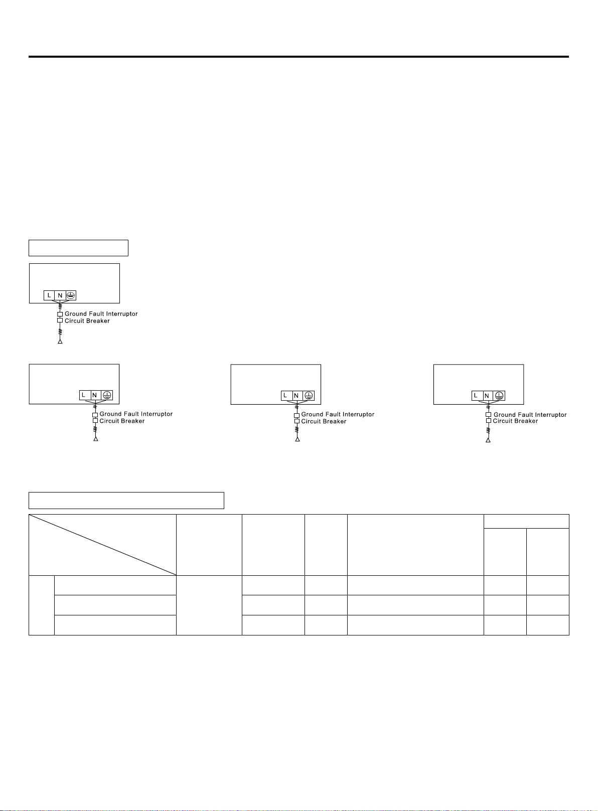
Power wiring gure
outdoor
Single-phase
power source: 1PH, 220-240V~, 50/60Hz
indoor 1
(wall mounted unit)
power source: 1PH, 220-240V~, 50/60Hz
indoor 2
(wall mounted unit)
power source: 1PH, 220-240V~, 50/60Hz
indoor 3
(non wall mounted unit)
power source: 1PH, 220-240V~, 50/60Hz
Indoor and outdoor use their individual power source. All indoors use one power source. Must install the leakage breaker
and the over current breaker, or electric shock will occur.
Outdoor power source and power cable
Model
power
Individual
Item
Power
source
AU032FSEUA
AU052FPEUA 10 40 40A 30mA below 0.1S 10 M5
AU072FPEUA 10 40 40A 30mA below 0.1S 10 M5
1PH,
220-240V~,
50/60Hz
Power cable
section
(mm2)
4 20 20A 30mA below 0.1S 4 M5
Circuit
breaker
(A)
Rated current of residual
circuit breaker (A)
Ground fault interruptor (mA)
response time (S)
Ground wire
Section
2
)
(mm
Screw
• Power cable must be xed rmly.
• To avide electrical shock, make sure to disconnect the power supply 1 minute or more before servicing the electrical
parts. Even after 1 minute,always measure the voltage at the terminals of main circuit capacitors or electrical parts and
before touching, make sure that those voltages are 50VDC or less.
• To persons in charge of electrical wiring work: Do not oerate the unit until the refrigerant piping is complete. (Running it
before the piping is ready will break the compressor)
• Each outdoor must be earthed well.
15
Page 18
Electric wiring and the application
• When power cable exceeds the range, thichen it appropriately.
• The appliance shall be installed in accordance with national wiring regulations.
• All wiring must be performed by an authorized electrician.
• Be sure to install an earth leakage circuit breaker in accordance with applicable legislation.Failure to do so many cause
electrical shock.
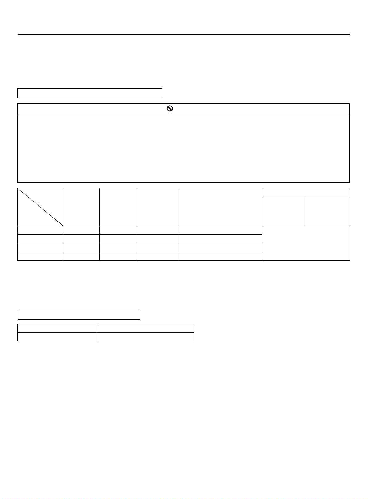
Indoor power source and communication wiring
PROHIBIT
• Power lines shall not use other wires other than copper wire.
• All internal and external machines must be connected to the ground of the power supply. The earthing wire shall not be
connected to the ground wire of the gas pipe, water pipe, lightning rod or telephone. If the grounding is not appropriate,
may cause electric shock or re.
• Power supply must be installed leakage circuit breaker, otherwise, may cause electric shock or re.
• The operation and maintenance of electrical equipment shall be carried out under the condition that the power supply
is cut o.
• The indoor and outdoor units set their own independent power supply.
• The signal line and the power line must be independent, non electric signal line access.
Item
Power cable
Indoor
total
current (A)
<10 2 23 20 20A, 30mA, below 0.1s
≥10 and <15 3.5 24 30 30A, 30mA, below 0.1s
≥15 and <22 5.5 27 40 40A, 30mA, below 0.1s
≥22 and <27 10 42 50 50A, 30mA, below 0.1s
• Power cable and communication wire must be xed rmly.
• Each indoor must be grounded well.
• When power cable exceeds the range, increase the gauge appropriately.
• Shielded layer of communication wires must be connected together and be earthed at single point.
• The total length of communication wire cannot exceed 1000m.
Communication wire for wired controller
Length of Signal Line (m) Wiring Dimensions
≤250 0.75mm
• The shielding lay of the signal line must be grounded at one end.
• The total length of the signal line shall not be more than 250m.
section
(mm2)
Wire length
(m)
Rated current
of overcurrent
breaker
(A)
2
× 3 core shielding line
Rated current of residual
circuit breaker(A)
Ground fault interruptor(mA)
response time(S)
Communication wire section
Outdoor/indoor
(mm
2-core × (0.75-2.0mm
2
)
shielded wire
Indoor/indoor
(mm2)
2
)
16
Page 19
Electric wiring and the application
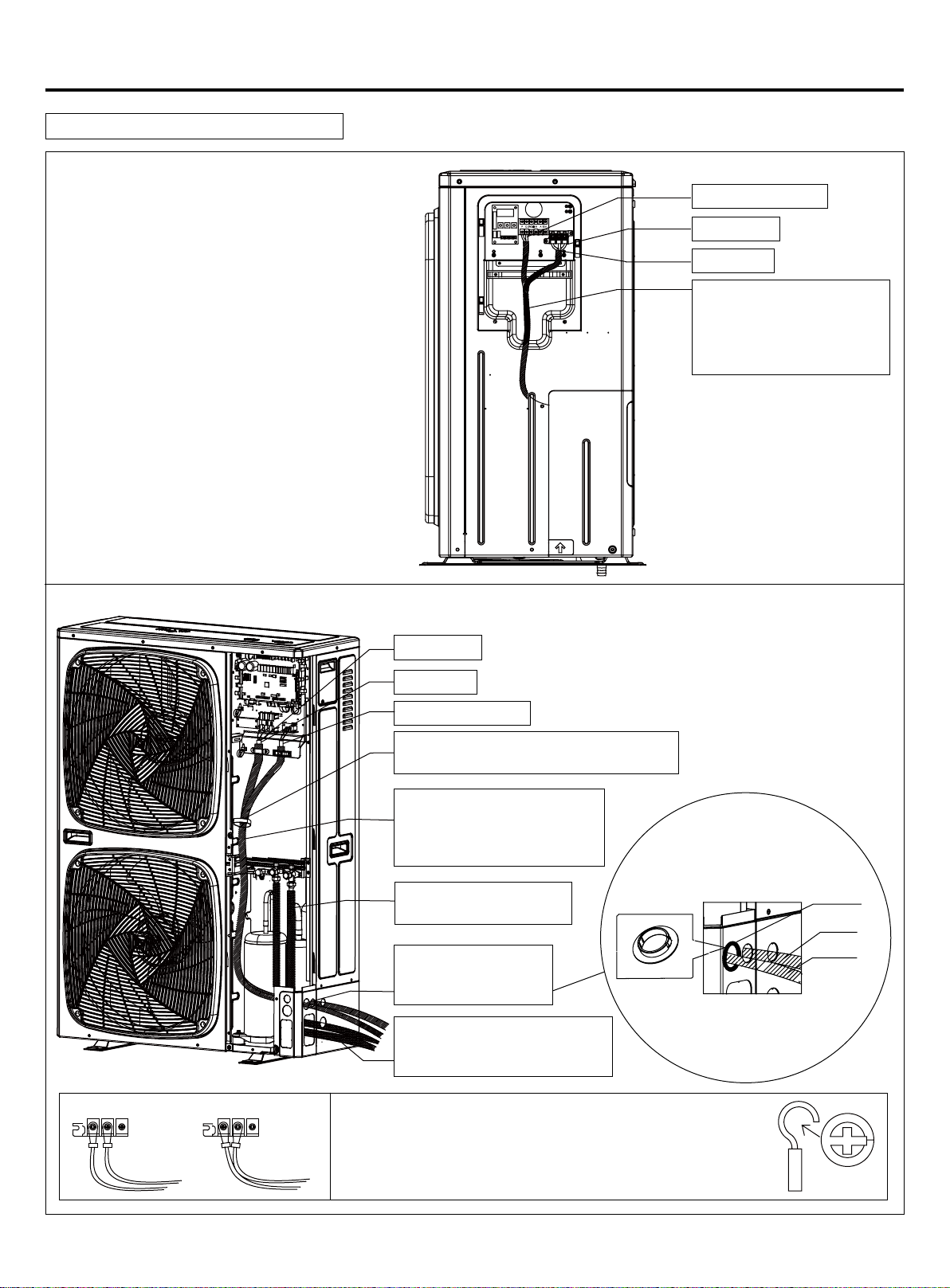
Outdoor unit electrical wiring diagram
Outdoor uint with single fan electrical wiring diagram
Communication line
Ground wire
Power cord
Power lines and
communication lines need to
be ame retardant and high
temperature resistant wire
wrap
Outdoor uint with double fan electrical wiring diagram
Ground wire
Power cord
Communication line
Fixing the power line and communication
line with a wire clip on the partition board
Power lines and communication
lines need to be ame retardant
and high temperature resistant
wire wrap
With plastic pipe insulation
on the refrigerant pipe
Protection of power line
and communication line
hole with wire sheath
Power line machinery and piping
need to be wrapped with ame
retardant tape
Cable sheath
Communication
line
Power cord
ErrorCorrect
When using a single terminal without terminal, the terminal can
not be directly used without ux. Otherwise, it will cause abnormal
heating of terminal crimping part. If a single core wiring is used in
the wiring, it can be connected directly in the manner shown in the
diagram.
17
Page 20
Installation and debugging
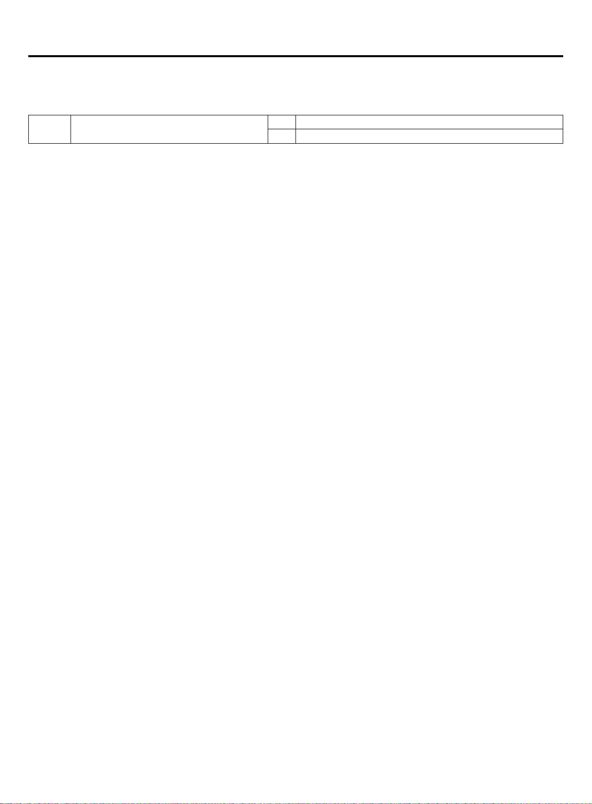
Outdoor unit PCB dipswitch setting, attention the dierent PCB version.
In the following table, 1 is ON, 0 is OFF.
BM1 introduction
BM1_1 Indoor searching after startup
Note:
Either indoor unit unlocked or the locked quantity dierent with actual connecting number, it cannot run.
0 Begin to search indoor
1 Stop searching indoor and lock the quantity
18
Page 21
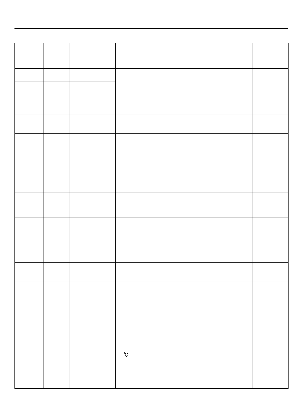
Failure code
Inverter outdoor unit failure code
Digital tube
indication
on master
unit
20 20-0
20-1 20-1
21 21
22 22
23 23
26 26-0
26-1 26-1
26-2 26-2
28 28
29 29
30 30
33 33 EEPROM failure EEPROM failure
34 34
35 35
43 43
Indication
on wired
controller
(hex)
Failure code
denition
Defrosting temp.
sensor Te failure
Defrosting temp.
sensor Tc failure
Ambient temp.
sensor Ta failure
Suction temp.
sensor Ts failure
Discharging temp.
sensor Td failure
Indoor
communication
failure
High pressure
sensor Pd failure
Low pressure
sensor Ps failure
High pressure
switch HPS failure
Discharging temp.
too high protection
(Td)
4-way valve
reversing failure
Discharging temp.
sensor Td too low
protection
Failure description Remarks
AD value is below 11(open circuit) or over 1012(short circuit)
for 60seconds, in cooling mode, if the sensor is abnormal,
the unit does not deal with it, besides, in defrosting and
within 3 minutes after defrosting, no alarm
AD value is below 11(open circuit) or over 1012(short
circuit) for 60seconds, in defrosting and within 3 minutes
after defrosting, no alarm
AD value is below 11(open circuit) or over 1012(short
circuit) for 60seconds, in defrosting and within 3 minutes
after defrosting, no alarm
After compressor is running for 5 minutes, AD value is below
11(open circuit) or over 1012(short circuit) for 60seconds,
in course of startup, defrosting and within 3 minutes after
defrosting, no alarm
For continuous 200 cycles, can not nd connected indoors
For continuous 300seconds, the searched indoor quantity is
less than the set quantity.
For continuous 300seconds, the searched indoor quantity is
more than the set quantity.
AD value is below 11(open circuit) or
over 1012(short circuit) for 30seconds,
in defrosting and within 3 minutes after
defrosting, no alarm
AD value is below 11(open circuit) or
over 1012(short circuit) for 30seconds,
in defrosting and within 3 minutes after
defrosting, no alarm
If disconnect for 50ms continuously, alarm. If alarm 3 times
in an hour, conrm the failure
Td≥239°F(115°C) at interval of 25msec for twice
continuously, and over the set value, then stop and alarm;
3 minutes later, resume automatically. If it occurs 3 times in
an hour, conrm the failure.
After 4-way valve is electried for 3 minutes, if the below
conditions can be met for continous 10 seconds, that is
conversing successfully:
1. this outdoor compressor is running normally
2. Pd-Ps≥87PSI(0.6MPa), Otherwise, the system alarms
reversing failure.
In normal operation, if Td<CT+50°F
(10
minutes and 50 seconds later, resume automatically. If it
occurs 3 times in an hour, conrm the failure. After xed
frequency compressor alarms, inverter compressor will
continue to run. If xed frequency compressor has been
locked for 3 times, the unit will stop and alarm.
Resumable
Resumable
Resumable
Resumable
Resumable
Resumable
Resumable
Once
conrmation,
un-resumable
Once
conrmation,
un-resumable
Once
conrmation,
un-resumable
Once
conrmation,
un-resumable
) for continuous 5 minutes, the unit stops and alarms.2
Once
conrmation,
un-resumable
19
Page 22
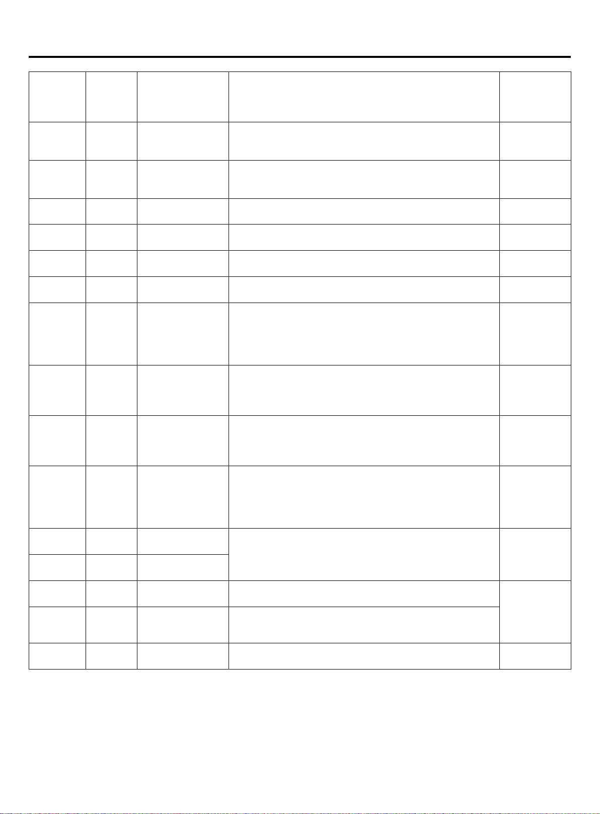
Failure code
Digital tube
indication
on master
unit
46 46
49 49
51-0 51-0
51-2 51-2
52-0 52-0
52-2 52-2
53 53
58 58
59 59
64 64
71-0 71-0
71-1 71-1
81 81
82 82
83 83
Indication
on wired
controller
(hex)
Failure code
denition
Communication
with inverter board
failure
"Low pressure
switch LPS failure"
LEVa current is too
high
LEVb current is too
high
LEVa broken line
fault
LEVb broken line
fault
CT current is too
low or current
sensor fault
Tc1 temp sensor
of valve plate
error(sending by
valve plate)
Tc2 temp sensor
of valve plate
error(sending by
valve plate)
CT current is too
high
Upper DC motor
blocked
Lower DC motor
blocked
IPM modular temp.
too high protection
Compressor
current protection
Outdoor model set
error
Failure description Remarks
No communication within 30 seconds continuously Resumable
If disconnect for 50ms continuously,alarm.If alarm 3 times in
an hour,conrm the failure
LEV driver chip detection Resumable
LEV driver chip detection Resumable
LEV driver chip detection Resumable
LEV driver chip detection Resumable
3 minutes after recovery
Tc1 temp. sensor cannot connect with valve plate module Resumable
Tc2 temp. sensor cannot connect with valve plate module Resumable
CT current exceeds specied value, 3 minutes after
recovery
Running at speed below 20rpm for 30s, or at speed of
70% lower than the target for 2 minutes, 2 minutes and 50
seconds later after stop, resume automatically. It occurs 3
times in an hour, conrm the failure.
IPM modular temp.≥185°F(85°C)
Compressor current exceeds specied value, 3 minutes
after recovery
Model and the number of fans do not match Un-resumable
"Once
conrmation,
un-resumable"
3 times in an
hour, conrm
failure; once
conrmation,
un-resumable
3 times in an
hour, conrm
failure; once
conrmation,
un-resumable
Once
conrmation,
un-resumable
3 times in an
hour, conrm
failure; once
conrmation,
un-resumable
20
Page 23
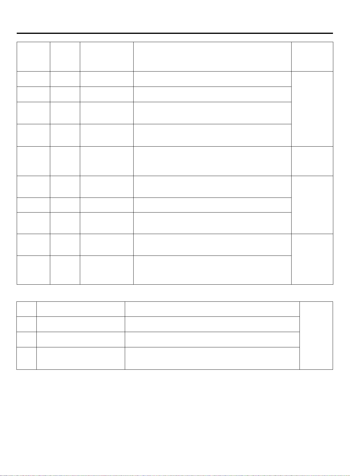
Failure code
Digital tube
indication
on master
unit
110 110
111 111
112 112
114 114
116 116
117 117
118 118
119 119
121 121
122 122
Indication
on wired
controller
(hex)
Failure code
denition
IPM modular
protection (F0)
Compressor out of
control
Radiator of
transducer temp.
too high
Voltage too low
of DC bus line of
transducer
Communication
abnormal between
transducer and
control PCB
Transducer over
current (software)
Compressor
startup failure
Detecting circuit of
transducer current
is abnormal
Power supply of
inverter board is
abnormal
Radiator temp.
sensor of
transducer
abnormal
Failure description Remarks
IPM modular over current, in short circuit, over heat, voltage
too low of control circuit.
In the course of compressor startup or running, the unit can
not detect the rotor position, or not connecting compressor.
Radiator temp. too high
Voltage of power source is too low
Communication is disconnected Resumable
Compressor startup fails for 5 times continuously, or
compressor is running down till stops caused by over
current or over heat
The sensor used for current detecting of transducer is
abnormal, disconnected or incorrectly connection
Current detection sensor of frequency controller is abnormal
or unconnected or connected wrongly.
Power supply of inverter board is broken down instantly
Resistor of temp.sensor abnormal or temp.sensor
disconnected
3 times in an
hour, conrm
failure; once
conrmation,
un-resumable
3 times in an
hour, conrm
failure; once
conrmation,
un-resumable
3 times in an
hour, conrm
failure; once
conrmation,
un-resumable
When there is no failure, if the starting condition can not be met, digital tube on master unit will display stand-by code:
555.0
555.1
555.3
555.b
Standby state of capacity
overmatch
Outdoor ambient temperature
too high (heating)
Outdoor ambient temperature
too high or too low (cooling)
The running mode of outdoor
unit does not match with the
indoor units.
When the ratio of indoor horse power and outdoor horse power is
less than 50% or more than 130%, the system is in standby mode.
Ta>27°C, Standby
Ta>54°C or Ta<-20°C, Standby
The outdoor unit maybe setted to cooling only or heating only.
21
Resumable
Page 24
Trial operation and the performance
Conrm the type of outdoor machine and the number of inside machine
• After installation, please conrm that the outdoor computer board BM1_1 is in the 0 state, and then to the unit power,
observe the digital display. If the number of the indoor machine and the outdoor machine type, the power supply voltage
is correct, then the BM1_1 dial to 1 of the state, if it is not correct, please check the dial machine communication code
and models, do not force the BM1_1 dial to 1 of the state, it may cause failure of the system.
5-minute delay function
• If starting up the unit after being powered o, the compressor will run about 5 minutes later against being damaged.
Cooling/heating operation
• Indoor units can be controlled individually, but cannot run in cool and heat mode at the same time. If the cool mode and
the heat mode are existing simultaneously, the unit set latter will be standby, and the unit set earlier will run normally. If
the A/C manager sets the unit at cooling or heating mode xedly, the unit can not run at the other modes.
Heating mode characteristic
• In operation if outdoor temp. arises, indoor fan motor will turn to low speed or stop.
Defrosting in heating mode
• In heating mode, outdoor defrosting will aect the heating eciency. The unit will defrost for about 2~10 minutes
automatically, at this time, the condensate will ow from outdoor, also in defrosting, the vapour will appear at outdoor,
which is normal. Indoor motor will run at low speed or stop, and outdoor motor will stop.
The unit operation condition
• To use the unit properly, please operate the unit under the allowed condition range. If operating beyond the range, the
protection device will act.
• The relative humidity should be lower than 80%. If the unit runs at the humidity over 80% for a long period, the dew on
the unit will drop down and the vapour will be blowed from air outlet.
Protection device (such as high pressure switch)
• High pressure switch is the device which can stop the unit automatically when the unit runs abnormally.
When the high pressure switch acts, the cooling/heating mode will stop but the running LED on wired controller will be
light still. The wired controller will display failure code.
When the following cases occur, the protection device will act:
In cooling mode, air outlet and air inlet of outdoor are clogged.
In heating mode, indoor lter is sticked with duct; indoor air outlet is clogged.
When protection device acts, please cut o the power source and re-start up after eliminating the trouble.
When power failure
• When power is failure in running, all the operations will stop.
• After being electried again, if with re-satrt up function, the unit can resume to the state before power o automatically;
if without re-satrt up function, the unit needs to be switched on again.
• When abnormal occurs in running because of the thunder, the lightning, the interference of car or radio, etc, please cut
o the power source, after eliminating the failure, press "ON/OFF" button to start up the unit.
Heating capacity
• The heating mode adopts the heat pump type that absorbs outdoor heat energy and releases into indoor. So if outdoor
temperature goes down, the heating capacity will decrease.
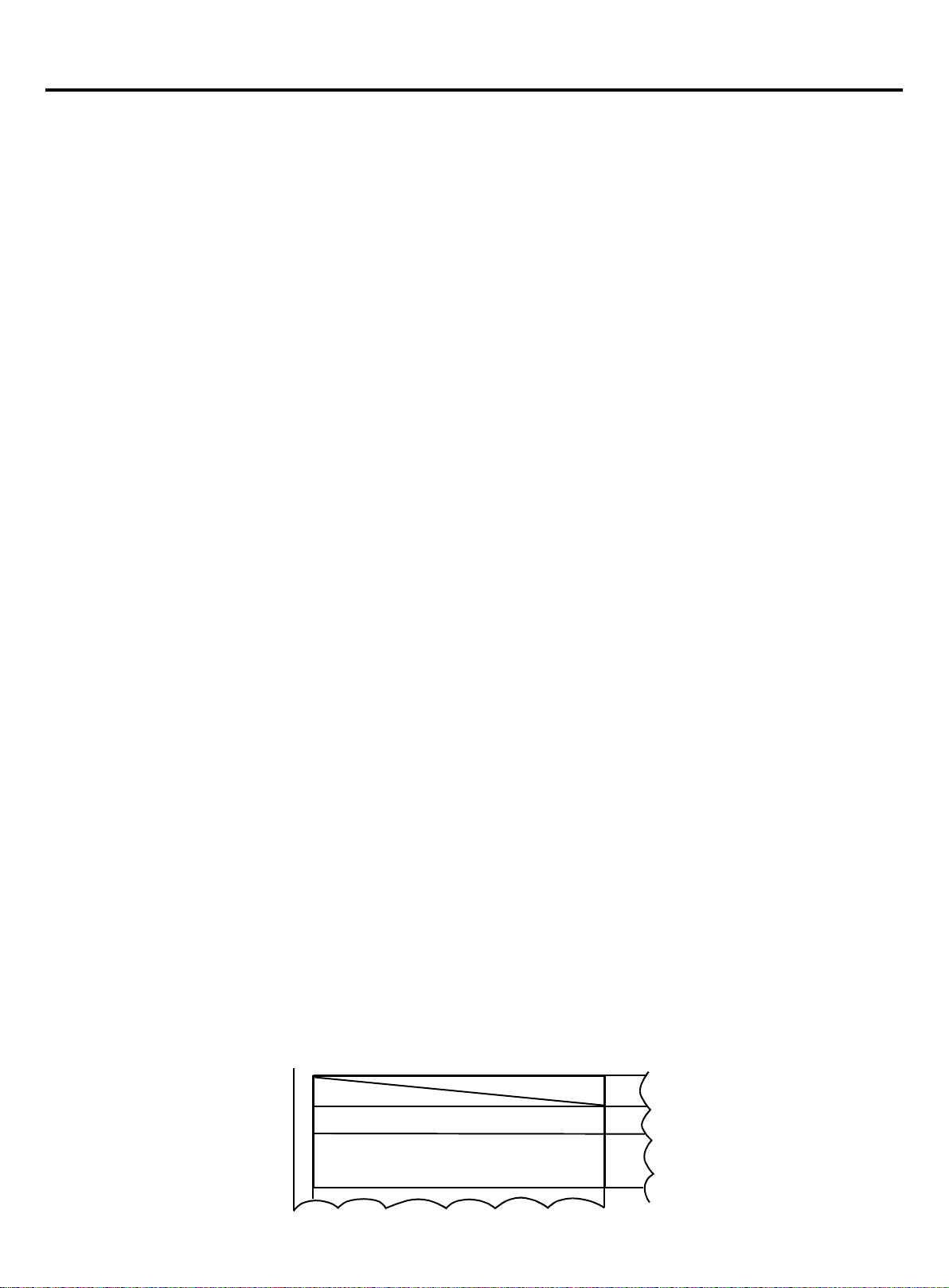
System marks
• On the condition that multi Outdoor systems are installed, in order to conrm the relationship between outdoor and
indoor, please make marks on outdoor electric control box cover to indicate the connected indoor unit. As the below
gure:
Indoor model:
Room No.
e.g. Indoor A, system 1, Floor 2 2F-1A
22
Page 25
Trial operation and the performance
Trial operation
• Before trial operation:
Before being electried, measure the resistor between power terminal block (live wire and neutral wire) and the earthed
point with a multimeter, and check if it is over 1MΩ. If not, the unit can not operate.
To protect compressor, electrify the outdoor unit for at least 12 hours before the unit runs.If the crankcase heater is not
electried for 6 hours, the compressor will not work.
Conrm the compressor bottom getting hot.
Except for the condition that there is only one master unit connected (no slave unit), under the other conditions, open
fully the outdoor operating valves (gas side, liquid side). If operating the unit without opening the valves, compressor
failure will occur.
Conrm all indoor units being electried. If not, water leakage will occur.
Measure the system pressure with pressure gauge, at the same time, operate the unit.
• Trial operation
In trial operation, refer to the information of performance section. When the unit can not start up at the room
temperature, make trial operation for outdoor.
23
Page 26
Move and scrap the air conditioning
• When moving, to disassemble and re-install the air conditioning, please contact your dealer for technical support.
• In the composition material of air conditioning, the content of lead, mercury, hexavalent chromium, polybrominated
biphenyls and polybrominated diphenyl ethers are not more than 0.1% (mass fraction) and cadmium is not more than
0.01% (mass fraction).
• Please recycle the refrigerant before scrapping, moving, setting and repairing the air conditioning; for the air conditioning
scrapping, should be dealt with by the qualied enterprises.
24
 Loading...