

Haier AE122FCAKA, AE072FCAKA, AE242FCAKA, AE142FCAKA, AE182FCAKA Instruction Manual
...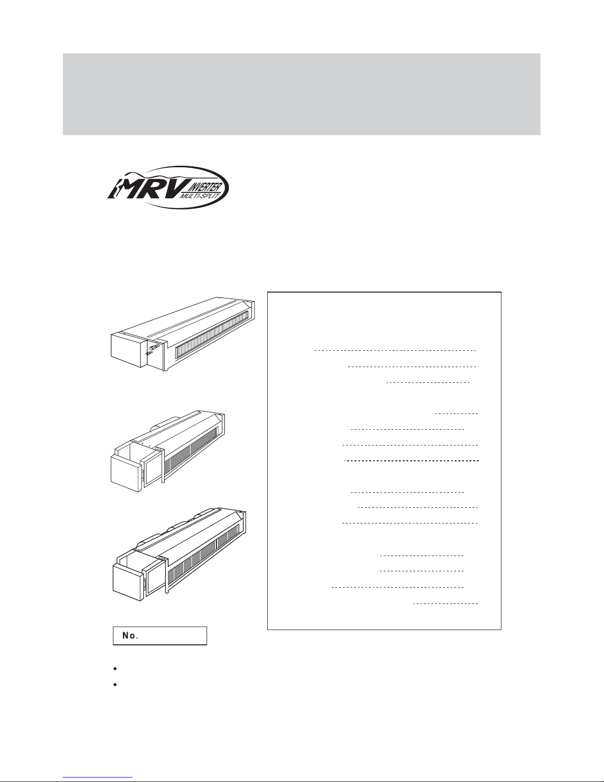
AE182FCAKA
0010573331
H-MRV
Ceiling Concealed Type Room Air Conditioner
CEILING CONCEALED TYPE AIR CONDITIONER INDOOR UNIT
AE212FCAKA
AE122FCAKA
AE142FCAKA
AE072FCAKA
AE092FCAKA
AE242FCAKA
AE09~212FCAKA
AE072FCAKA
AE242FCAKA
Before Application
Cautions
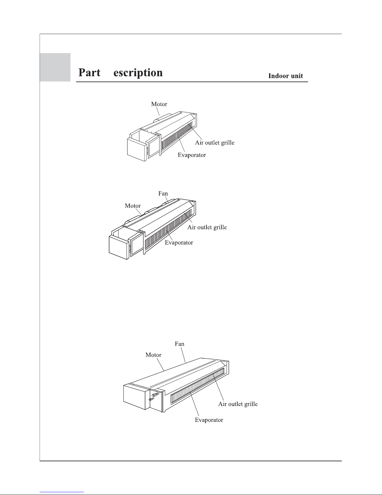
Part Description
Important Points of Safety
Operating Instructions
AUTO,COOL, DRY,HEAT Operation
TIME Operation
Sleep Function
Health Function
Maintenance
Trouble Shooting
When Fault Occurs
Notice to Users
Indoor Unit Installation
Installation Precautions
Installation Procedure
Malfunction
Installation Check and Trial Run
1-2
3-8
9-11
12
13-14
15
16
17-18
19
20
21-22
23-33
34-35
36
Contents
Please read this manual carefully before use.
Please keep it attentively for future use.
INSTRUCTION
MANUAL
1
Cautions
2
Cooling
Heating
Indoor
outdoor
Rated Maximum Minimum
27 32 18
19 23 14
35 43 -5
24 26 - 20 27 15
14.5 -- - 7 24 -15
6 18 --
DB C
WB C
DB C
WB C
Indoor
outdoor
DB C
WB C
DB C
WB C
Cautions
3
AE092FCAKA , AE122FCAKA , AE142FCAKA , AE182FCAKA , AE212FCAKA have the Return air
box (see the following picture) when shipping from the factory and they are back-side return air. During
the installation, also can be changed to Down-side Return air according to the user's need.
AE09~212FCAKA
AE072FCAKA
AE242FCAKA
D
4
fig(1)
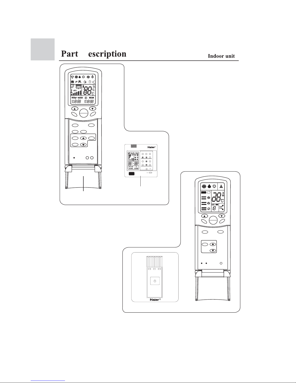
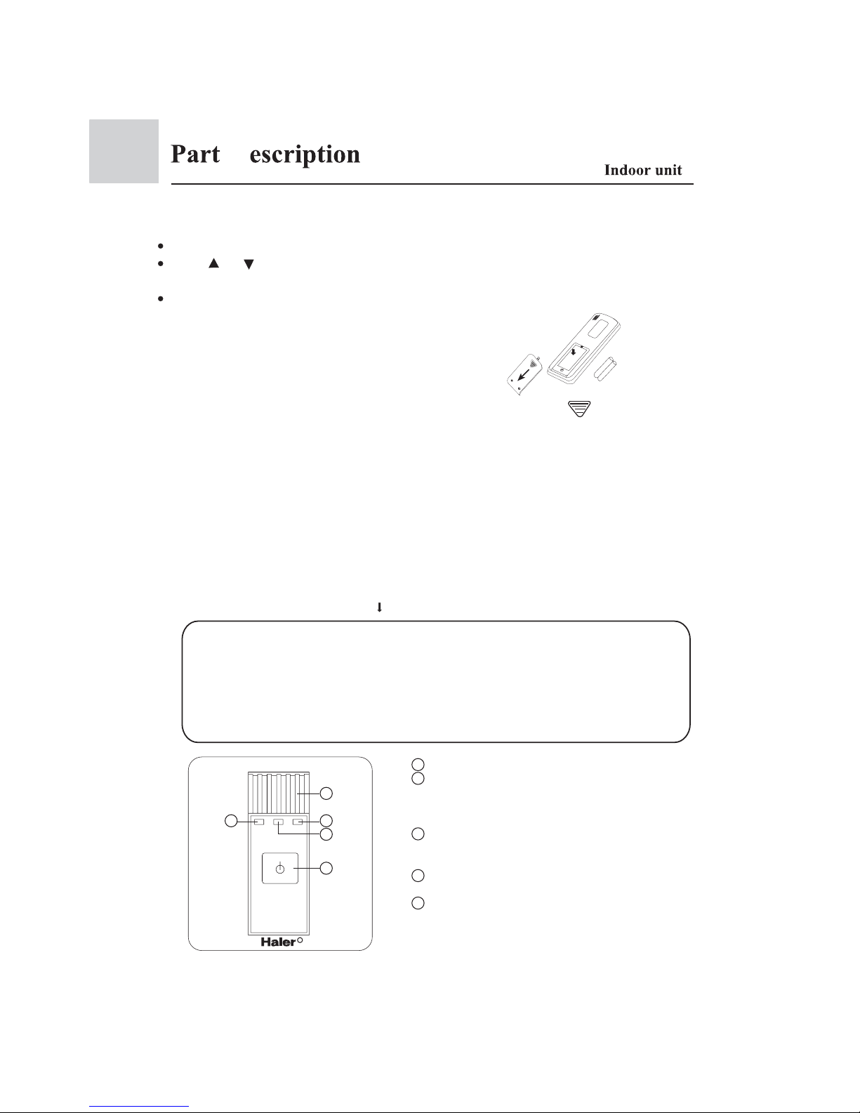
Left picture is a wired remote controller, which can be
used on AE072FCAKA(wired control), AE092FCAKA
(wired control), AE122FCAKA(wired control),
AE142FCAKA(wired control),AE182FCAKA(wired
control),AE212FCAKA(wired control), AE242FCAKA
(wired control). The remote controller can be purchased
extrally.
R
OFF
H
AUTO
io
n
Wired remote Controller using method:
1.Use one wired remote controller. See fig (1)
2.Also can buy a remote controller extrally, realize wired
remote control + remote control dual control modes.
The right figure is a remote controller, which can be used
on AE072FCAKA(remote control), AE092FCAKA(remote
control), AE122FCAKA(remote control), AE142FCAKA
(remote control),AE182FCAKA(remote control),
AE212FCAKA(remote control), AE242FCAKA(remote
control) and the matching remote control receiver
Remote control receiver using
method :
Use remote controller control
the remote control window of
the remote control receiver.
fig(2)
SWING
CODE
RESET
HEALTH
FAN
TEMP
MODE
LOCK
TIMER
ON
OFF
SWING
FRESH
SET
LOCK
RESET
HEALTH
FAN
TEMP
MODE SLEEP
CLOCK
TIMER
ON
OFF
LIGHT
SET
ROOM
MODE
FAN
TEMP
CLOCK SET
TIMER SLEEP
RESET
FILTER RESET
HEALTH
SWING
C
ON
OFF
*
AUTO
ON/OFF
Remote controlller (1)
Wire remote controlller
Remote controlller is an accessory, to be ordered extrally
Remote controlller (2)
Remote receiver (2)
D
B A
5
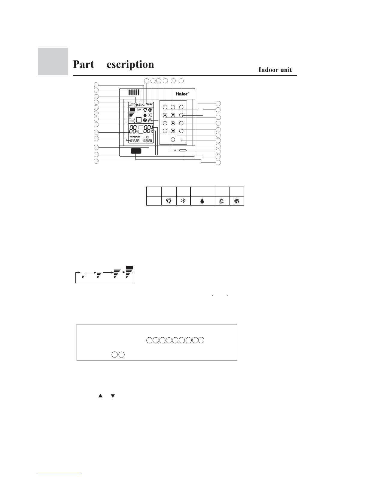
14.Network control display
Used to adjust the
time of timer and
clock
When the wire
controller appears
abnormal condition,
use a sharp-pointed
article to press this
button to make the
wire controller
resume normal
After cleaning the
air inlet, press this
button, the unit
can start to operate
12.Humidifying state display
Used to turn on/off unit
1.ON/OFF button
6.Air filter cleaning display
*
7.Super/Soft operation display
13.Sleep state display
2.Temperature display
24.Time Adjusting
button
23.Sleep button
Used to set Sleep
state
When there is too much dust
collected on the air inlet, the
wire controller will show
this display to remind the
user to clean the air inlet.
After cleaning and installation,
just press the air filter reset button.
8.Fan speed display
9.Auto Swing display
11.Fresh air state display
25.Reset button
26.Air Filter Reset
button
27.Timer button
Used to set the
mode of timer
28.Lock state display
4.Timer ON/OFF display
3.Clock display
17.Operation mode button
5.Humidity display
22.Setting button
Used to confirm
the time of timer
and clock
15.Working mode display
21.Clock button
Used to calibrate the time of
timer and clock
16.Electric heating display
Used to set working mode:
Auto, Cooling, Dehumidifying,
Heating, Fan
18.Fan speed button
Used to set fan speed: Low
Fan, Med Fan, High Fan, Auto
20.Temperature Setting button
SUR
1
2
3
4
5
6
7
8
9
11
12
13
14 15 16 17 18
20
21
22
23
24
25
26
27
28
AUTO
10.Health state display
Used to set temperature,
temperature range: 16 C~30 C
10
19
19.Swing button
Used to set Auto Swing or
Fixed air sending direction
Calibration of clock
When turning on the unit for the first time, the clock should be calibrated. The method
of calibration is:
1.Press ì Clockî button, the Clock display ì AMî ì PMî will flash.
2.Press or to adjust time. For each press, the time will increase or decrease 1
*minute. If depressing the button, the time will increase or decrease rapidly.
3.After confirming the time, press ì Setî button, ì AMî or ì PMî will stop flashing,the
clock will begin to work.
Note:
1.This model does not have the following related
display and function
2.The outdoor unit no oxygen-bar function or no negative ion
unit no healthl function display.
Auto
Low Fan Med Fan High Fan Auto
Working
mode
Auto
operation
Cooling
operation
Dehumidifying
operation
Heating
operation
Fan
operation
Wire
controller
MODE
FAN SWING
TEMP
CLOCK
SET
TIMER
SLEEP
RESET
FILTER RESET
ON/OFF
SET
HEALTH
29
30
5 6 7 9
19
10
11
12
14
16
26
29.Health
Used to control the
generating oxygen
function and negative
ion-function
30.Remote control window
Used to receive the
remote control signal
D
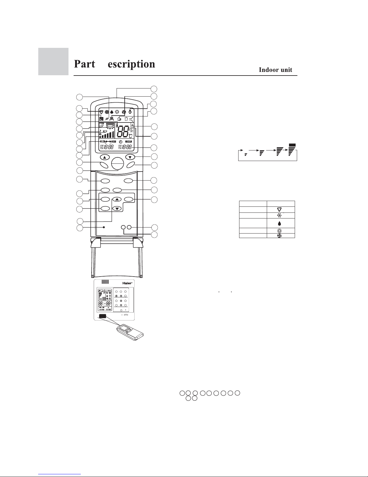
1.This unit no the above function and display
2.The outdoor unit no oxygen-bar function ot no functions fo non-negative ion unit.
3.When using remote controller, first point it to the receiving window of wire controller, and then operate
remote controller.A ì tickî tone will be uttered to indicate a right acceptance.
4.All the buttons except the sleeping button is no effective after wire controller received lock signal from
remote controller.
6
Used to turn on/off unit
Note: Wired remote
controller his key have compl
cooling running function.
16.Fan speed display
19.Auto Swing display
26.Fresh air state display
15.Timer ON/OFF display
18.Clock display
23.Health state display
Auto
Low Fan Med Fan High Fan Auto
20.Humidifying state display
When the wire
controller appears
abnormal condition,
use a sharp-pointed
article to press this
button to make the
wire controller
resume normal
6.Time Adjusting button
11.Sleep button
7.Reset button
29.Lock state display
13.Setting button
Used to confirm
the time of timer
and clock
2.Operation mode button
4.Clock button
Used to calibrate the time
of timer and clock
24.Electric heating display
Used to set working mode:
Auto, Cooling,
Dehumidifying,
Heating, Fan
10.Fan speed button
Used to set fan speed: Low
Fan, Med Fan, High Fan, Auto
9.Temperature Setting button
8.Swing button
Used to set Auto Swing or
Fixed air sending direction
22.Working mode display
Working mode
Auto operation
Cooling operation
Dehumidifying
operation
Heating operation
Fan operation
Remote controller
5.Timer button
Used to set the
mode of timer
SWING
FRESH
SET
LOCK
RESET
LIGHT
HEALTH
FAN
TEMP
MODE SLEEP
CLOCK
TIMER
ON
OFF
1
2
3
4
5
6
7
8
9
10
11
12
13
14
15
16
17
18
19
29
28
27
25
24
26
20
21
22
23
30
31
Make sure that the remote controller is used within 7 meters from receiver window of the wire
controller and there are no obstructions in between.
The remote controller or wire controller should be handled with care.
When operating the remote controller in an area where electronically controlled lights are installed
or wireless handsets are used, move closer to the indoor unit as the function of the remote controller
might be affected by signals from this equipment.
Used to set temperature,
temperature range: 16 C~30 C
Remote LCD display contents and key name and each key function introduction
3.Health
Used to control the
generating oxygen function
and negative ion-function
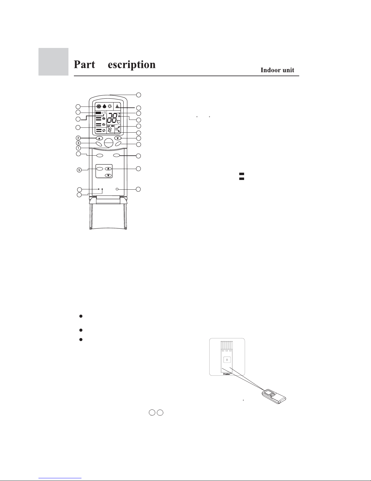
1.ON/OFF button
12.Fresh air
Used to set fresh air function
14.Lock button
Used to lock the operating
key and LCD contents
17.Battery energy display
21.Sleep mode display
Display when the health
running
25.Comfort running display
23.Temperature display
Used to display the setting
temperature and room temp.
27.Signal launch display
31.Signal lauch head
30.Light button
Used to realize control board
VFD light stable,light weaker,
light shut off etc.
8 12 17 19 20 24 25 26 30
Remote controller
(Operation of remote controller)
3 23
Note:
SET
ROOM
MODE
FAN
TEMP
CLOCK SET
TIMER SLEEP
RESET
FILTER RESET
HEALTH
SWING
C
ON
OFF
*
AUTO
ON/OFF
D
7
TEMP
HEALTH
FAN
MODE
SWING
TIMER
ON
OFF
LOCK
RESET
Make sure that the remote controller is used within 7 meters from receiver window
of the wire controller and there are no obstructions in between.
The remote controller or wire controller should be handled with care.
When operating the remote controller in an area
where electronically controlled lights are
installed or wireless handsets are used, move
closer to the indoor unit as the function of the
remote controller might be affected by signals
from this equipment.
1.ON/OFF button
Used to turn on/off unit
2.Temperature Setting button
Used to set temperature,
temperature range: 16 C~30 C
4.Operation mode button
Used to set working mode:
Cooling, Dehumidifying,
Heating
5.Timer button
Used to set the
mode of timer
When the remote
controller appears
abnormal condition,
use a sharp-pointed
article to press this
button to make the
wire controller
resume normal
6.Reset button
7.Fan speed button
Used to set fan speed
8.Swing button
Used to set Auto Swing or
Fixed air sending direction
9.Time Adjusting button
11.Working mode display
12.Fan speed display
14.Timer ON/OFF display
18.Super/Soft operation display
Remote LCD display contents and key name and each key function introduction
3.Health
Used to control the
generating oxygen function
and negative ion-function
10.Lock button
Press on time lock all the
key sand press another time
concel the lock.
Used to display the fan
speed. After setting
"AUTO" function,air speed
can auto change according
to the temp. difference
between the room temp. and
setting temp.
20.Signal launch head
Use to send signal to the
indoor unit receive window.
19.Timing time display
Display timing open time
or timing close time
17.Lock display
Display the key have been
locked.
16.Temperature display
Display the setting temp.
value.
15.Signal display
Sending out signal to the
remote receiver.
13.Health running display
Used to display healthy
running.
R
Display Timing mode.
"Blank" No Timing
" " Timing off
" " Timing on
CODE
21.Code
Select remote control receive
code(H-MRV Remote cnotrol
type use A code)
OFF
ON
OFF
H
AUTO
ion
6
4
2
7
8
9
10
12
13
14
15
16
17
18
19
11
20
Note:
1.After change the battery, working condition resume as follows:
Working mode:cooling Temp. 26 C
Timming mode: normal Air speed: Auto
2.The units used in this manual no 8 18 functions. The health key can only control the
negative generator.
D
21
B A
8
R
Battery loading
Batteries are fitted as follows:
Note:
It is recommended that the batteries be removed from the compartment if the remote
controller is not used for an extended period.
The remote controller is programmed for automatic test of operation mode after the
batteries are replaced. When the test is conducted, all icons will appear on the screen
and then disappear if the batteries are properly fitted.
When the display become weak, this display no power in the battery, please change the
battery.
Loading the battery
Ensure that batteries are correctly placed in the compartment as required for positive and
negative terminals.
Replacing the battery compartment lid
The battery compartment lid is reinstalled in the reverse sequence.
Display review
Press the button to see if batteries are properly fitted. If no display appears, refit the batteries.
Remove the battery compartment lid
Slightly press and disengage the battery compartment lid marked with ì î and then hold
the remote controller by the upper section and then remove the battery compartment lid by
pressing in the direction of the arrow as shown in the figure above.
Caution:
If the remote controller does not operate as designed after fitting new batteries of the same
type, press the Reset button (marked ) with a pointed article.
Clock set
When unit is started for the first time, clock should be adjusted as follows:
Press CLOCK button, "AM"or "PM" flashes.
Press or to set correct time. Each press will increase or decrease 1min. If the
button is kept depressed, time will change quickly.
After time setting is confirmed, press SET, "AM "and "PM" stop flashing, while clock
starts working.
1 .Emergency switch
2 .Power lamp
After open the unit, this lamp bright when the
unite enter health running, the lamp change from
orange to blue lamp.
3 .Timing lamp
When the unit been setting Timing running, this
lamp bright.
4 .Running lamp
When the compressor working, this lamp bright.
5 .Indoor temp. sensor
Test the room temperature.
* *
* *
1
3
4
5
2
D
Important Points of Safety
The following four important points of safety and suggestions should be paid great attention:
Warning: Misuse may cause fatal result such as death or serious injury etc.
Attention: Misuse may cause human injury or damage of machine, in some case
fatal results.
: Content marked with this ì forbiddenî sign should be absolutely forbid den, otherwise may cause damage of machine and human injury of the
user.
: Content marked with this ì compulsoryî sign should be executed comp ulsively, otherwise may cause damage of machine and human injury of
the user.
Comply with the following important points of safety.
Put these important points of attention and suggestions nearby and convenient for reference in need.
Hand over this instruction manual to new user if you resell this machine.
Warning for installation
Entrusted Installation
Installation of the machine should
be entrusted to certified person of
after service. Unauthorized installation may cause water leakage,
electric shock or fire hazard for
improper operation.
To prevent leakage of refrigerant,
let certified person of after service
do it.
Leakage of refrigerant over certain
consistence may result in shortage
of oxygen. Enough precautions
MUST be done to avoid oxygen
shortage in case of refrigerant leaking if the room where the airconditioner is installed is small.
The power supply must be fitted with
earth line to ensure valid earthing of
the air-conditioner. No or incomplete
earthing connection may cause the
risk of electric shock.
!
!
!
!
!
Test run
After indoor units are installed,all
cassettes hinded models should be
tested.when the units are confirmed
to be normal,other fitments can be
installed.
!
!
9
Warning
!
Important Points of Safety
Warning
Avoid your body being blown
directly by cold wind for long
period, otherwise your health
may be affected.
Donít extend your fingers or
any other article into the inlet
or outlet during operation of
the machine for touching re volving fans may cause human
injury or damage of machine.
If something abnormal (e.g.: burnt
smell etc.) occurs, stop running the
machine, shut down the manual
power switch and contact after
service. Continuous operation in
disorder may cause fire hazard or
electric shock etc.
Warning for use
Warning for move and repair
When you have to disassemble
and reinstall the machine, entrust
it to after service. Improper inst allation may cause fire hazard,
electric shock or damage of ma chine.
Unauthorized alteration or repair
work is strictly forbidden. Impr oper alteration or maintenance
may cause fire hazard, electric
shock or water leakage. Repair
work should be entrusted to cert ified person of after service.
Attention
Attention points for installation
Ensure the drainage hose work
normally during installation.
Improper installation of drainage
can cause water leakage and
damp articles.
DO NOT install the machine in
place where flammable gas
releases easily to avoid fire
hazard.
Ensure electric leakage breaker
being installed. Electric leakage
breaker MUST be installed,
otherwise electric shock may be
caused.
If the power supply cord is
damaged, call a certified
electrician of the manufacturer
or other maintenance department
to replace it.
! !
!
!
10
!
!
11
Important Points of Safety
Attention
Attention points for use
* Ensure ventilation of the room
if the machine is used with
burning facilities. Deficient
ventilation can cause oxygen
shortage.
* Check whether installation
bench of the machine is
damaged after a long period
of use. Machine on damaged
bench may fall down and cause
human injury or other damage.
* In place where winds produced
by the machine can reach, donít
lay any animals or plants which
may be hurt otherwise.
* Donít put vases containing water
or other else on the unit assembly.
Otherwise, the machine may be
immersed internally and result in
bad electric insulation causing
electric shock.
* The is machine CANNOT be
used for the purpose of prese rving food, animals, plants,
precision instruments and
artwork etc., which may be
destroyed otherwise.
* DONíT replace fuse with ma terial other than fuse of proper
capacity. Replacing fuse with
metal wire or copper etc. can
cause fire hazard or other faults.
* DONíT lay any burning facilities
in place where winds produced by
the machine can reach. Incomplete
combustion of burning facility may
be caused otherwise.
* DONíT clean the machine with
water. Electric shock may occur
otherwise.
* DONíT put flammable spray
articles nearby or spray them to
the machine. Fire hazard may
occur otherwise.
* DONíT operate switch with wet
hand. Electric shock may occur
otherwise.
* Stop operation and shut down
manual power switch before
cleaning and maintenance.
* The power supply MUST be of
rated voltage and connected with
special electrical supply circuit.
!
 Loading...