

Page 1
No.
0150503056 C
Please read this manual carefully before using this air conditioner
Please keep this manual safely for future use
DUCT TYPE 100Pa
INDOOR UNIT
ON-OFF
AD282AHEAA
AD362AHEAA
AD482AHEAA
AD602AHEAA
INVERTER
AD362AHERA
AD482AHERA
AD602AHERA
OPERATION MANUAL
INSTALLATION MANUAL
EN
MANUALE DI ISTRUZIONI
MANUALE DI INSTALLAZIONE
IT
MANUEL D’INSTRUCTIONS
MANUEL D’INSTALLATION
FR
BEDIENUNGSANLEITUNG
INSTALLATIONSANLEITUNG
DE
MANUAL DE INSTRUCCIONES
MANUAL DE INSTALACIÓN
ES
R410A UNITARY SMART
Page 2

Page 3
AD282AHEAA AD362AHEAA AD482AHEAA AD602AHEAA AD362AHERA AD482AHERA AD602AHERA
CE
Tutti i prodotti sono conformi alle seguenti normative europee:
- Direttiva 73/23/EEC Basso Voltaggio
- Direttiva 2006/95/EC Basso Voltaggio
- Direttiva 89/336/EEC Compatibilità elettromagnetica
ROHS
Il prodotto è conforme alla normativa 2002/95/EEC sulla restrizione d’uso di
sostanze inquinanti negli apparecchi elettrici ed elettronici.
WEEE
Informativa al consumatore come previsto dalla normativa europea
2002/96/CE riguardante i rifiuti di apparecchiature elettriche ed elettroniche.
SPECIFICHE DI SMALTIMENTO:
Il climatizzatore è contrassegnato con questo simbolo,
ciò significa che i prodotti elettrici ed elettronici non
possono essere smaltiti insieme ai rifiuti domestici non
differenziati. Non cercare di demolire il sistema da soli:
la demolizioni dei sistemi di condizionamento, nonché il
recupero del refrigerante, dell’olio e di qualsiasi altra
parte devono essere eseguiti da un installatore qualifi-
cato in conformità alla legislazione locale e nazionale
vigente in materia.I climatizzatori devo essere trattati presso una struttura specializzata nel riutilizzo, riciclaggio e recupero dei materiali. Il corretto smaltimento del prodotto eviterà le possibili conseguenze negative all’ambiente e alla
salute dell’uomo. Per maggiori informazioni contattare l’installatore o le autorità locali. Le batterie devono essere tolte dal telecomando e smaltite separatamente conformemente alla legislazione locale e nazionale vigente in materia.
CONFORMITÀ ALLE DIRETTIVE EUROPEE PER I MODELLI:
Haier Industrial Park, No.1 Haier Road, Qingdao, P.R.China
IT
AD282AHEAA AD362AHEAA AD482AHEAA AD602AHEAA AD362AHERA AD482AHERA AD602AHERA
CE
All the products are in conformity with the following European provision:
- Low Voltage Directive 73/23/EEC
- Low Voltage Directive 2006/95/EC
- Electromagnetic CompatibilitY 89/336/EEC
ROHS
The products are fulfilled with the requirements in the directive 2002/95/EEC of the
European parliament and of the council on the Restriction of the use of Certain Hazardous Substances in Electrical and Electronic Equipment (EU RoHS Directive)
.
WEEE
In accordance with the directive 2002/96/CE of the European parliament,
herewith we inform the consumer about the disposal requirements of the
electrical and electronic products.
DISPOSAL REQUIREMENTS:
Your air conditioning product is marked with this sym-
bol. This means that electrical and electronic products
shall not be mixed with unsorted household waste.
Do not try to dismantle the system yourself: the dis-
mantling of the air conditioning system, treatment of
the refrigerant, of oil and of other part must be done
by a qualified installer in accordance with relevant
local and national legislation.
Air conditioners must be treated at a specialized treatment facility for re-use,
recycling and recovery. By ensuring this product is disposed of correctly, you
will help to prevent potential negative consequences for the environment and
human health. Please contact the installer or local authority for more information. Battery must be removed from the remote controller and disposed of
separately in accordance with relevant local and national legislation.
EUROPEAN REGULATIONS CONFORMITY FOR THE MODELS:
EN
AD282AHEAA AD362AHEAA AD482AHEAA AD602AHEAA AD362AHERA AD482AHERA AD602AHERA
CE
Tous les produits sont conformes aux directives européennes suivantes:
- Directive 73/23/CEE Basse tension
- Directive 2006/95/CE Basse tension
- Directive 89/336/CEE Compatibilité électromagnétique
ROHS
L'appareil est conforme à la directive 2002/95/CEE relative à la limitation de
l'utilisation de certains substances dangereuses dans les équipements électriques et électroniques.
DEEE (WEEE)
Information au consommateur comme le prévoit la directive européenne
2002/96/CE relative aux déchets d'équipements électriques et électroniques.
SPECIFICATIONS POUR L'ELIMINATION:
Ce pictogramme, apposé sur le climatiseur, signifie
que les équipements électriques et électroniques ne
peuvent pas être éliminés avec les déchets ménagers
non triés. Ne pas essayer de démanteler l'équipement
soi-même: le démantèlement des systèmes de clima-
tisation, ainsi que la récupération du frigorigène, de
l'huile et de toute autre partie doivent être effectués
par un installateur qualifié conformément à la législation locale et nationale en vigueur en la matière. Les climatiseurs doivent être
traités dans un centre spécialisé dans la réutilisation, le recyclage et la valorisation des matériaux. L'élimination correcte de ces appareils permet d'éviter les effets nocifs sur l'environnement et la santé humaine. Pour plus de
renseignements contacter l'installateur ou les autorités locales. Les piles doivent être retirées de la télécommande et éliminées séparément, conformément à la législation locale et nationale en vigueur en la matière.
CONFORMITÉ AUX DIRECTIVES EUROPÉENNES POUR LES MODÈLES:
FR
Page 4
Haier Industrial Park, No.1 Haier Road, Qingdao, P.R.China
AD282AHEAA AD362AHEAA AD482AHEAA AD602AHEAA AD362AHERA AD482AHERA AD602AHERA
CE
Alle Produkte erfüllen die folgenden europäischen Richtlinien:
- Niederspannungsrichtlinie 73/23/EWG
- Niederspannungsrichtlinie 2006/95/EG
- EMV-Richtlinie 89/336/EWG
ROHS
Das Produkt erfüllt die Richtlinie 2002/95/EWG zur Beschränkung der Verwendung bestimmter gefährlicher Stoffe in Elektro- und Elektronikgeräten.
WEEE
Verbraucherinformation laut europäischer Richtlinie 2002/96/EG zu Elektround Elektronik-Altgeräten.
HINWEISE ZUR ENTSORGUNG:
Das Klimagerät ist mit diesem Symbol gekennzeich-
net, das darauf hinweist, dass Elektro- und Elektronik-
geräte getrennt vom Hausmüll entsorgt werden müs-
sen. Verschrotten Sie die Anlage nicht selbst: die Ver-
schrottung von Klimaanlagen, sowie die Rückgewin-
nung des Kältemittels, des Öls und aller sonstigen Tei-
le müssen durch einen qualifizierten Installateur in
Übereinstimmung mit den einschlägigen geltenden
örtlichen und nationalen Vorschriften erfolgen. Die Klimageräte müssen bei
einem Unternehmen entsorgt werden, das auf die Verwertung, das Recycling
und die Rückgewinnung der Materialien spezialisiert ist. Die richtige Entsorgung des Produkts hilft negative Auswirkungen auf Umwelt und Gesundheit
zu vermeiden. Für weitere Informationen wenden Sie sich bitte an den Installateur oder die örtlichen Behörden. Die Batterien müssen aus der Fernbedienung entfernt und in Übereinstimmung mit den einschlägigen geltenden örtlichen und nationalen Vorschriften getrennt entsorgt werden.
ÜBEREINSTIMMUNG MIT DEN EUROPÄISCHEN RICHTLINIEN FÜR DIE MODELLE:
DE
AD282AHEAA AD362AHEAA AD482AHEAA AD602AHEAA AD362AHERA AD482AHERA AD602AHERA
CE
Todos los productos están en conformidad con las siguientes Normativas
Europeas:
- Bajo Voltaje directiva 73/23/EEC
- Bajo Voltaje directiva 2006/95/EC
- Compatibilidad electromagnética 89/336/EEC
ROHS
Los productos cumplen los requisitos de la directiva 2002/95/EEC del parlamento Europeo y el consejo regulador Del uso de materiales peligrosos en
equipamientos eléctricos Y electrónicos. (EU RoHS Directiva).
WEEE
De acuerdo con la directiva 2002/96/CE del parlamento Europeo, Informamos al consumidor acerca del reciclage de los productos Electrónicos y
eléctricos.
REQUISITOS PARA LA ELIMINACIÓN:
Su acondicionador de aire está marcado con este
símbolo. Esto significa que los productos eléctricos y
electrónicos no deben mezclarse con el resto de resi-
duos domésticos no clasificados.
No intente desmontar el sistema usted mismo: El des-
mantelamiento del acondicionador de aire, así como
el tratamiento del refrigerante, aceite y otros compo-
nentes, debe ser efectuado por un instalador competente de acuerdo con las normas locales y nacionales aplicables. Los acondicionadores de aire deben ser tratados en instalaciones especializadas para
su reutilización, reciclaje y recuperación. Al asegurarse de desechar este producto de la forma correcta, està contribuyendo a evitar posibles consecuencias negativas para el entorno y para la salud de las personas. Contacte, por
favor, con el instalador o con las autoridades locales para obtener más información. Las pilas del control remoto deben extraerse y eliminarse por separado y de acuerdo con la normativa local y nacional aplicable.
CONFORMIDAD EUROPEA DE LAS REGULACIONES PARA LOS MODELOS:
ES
Page 5
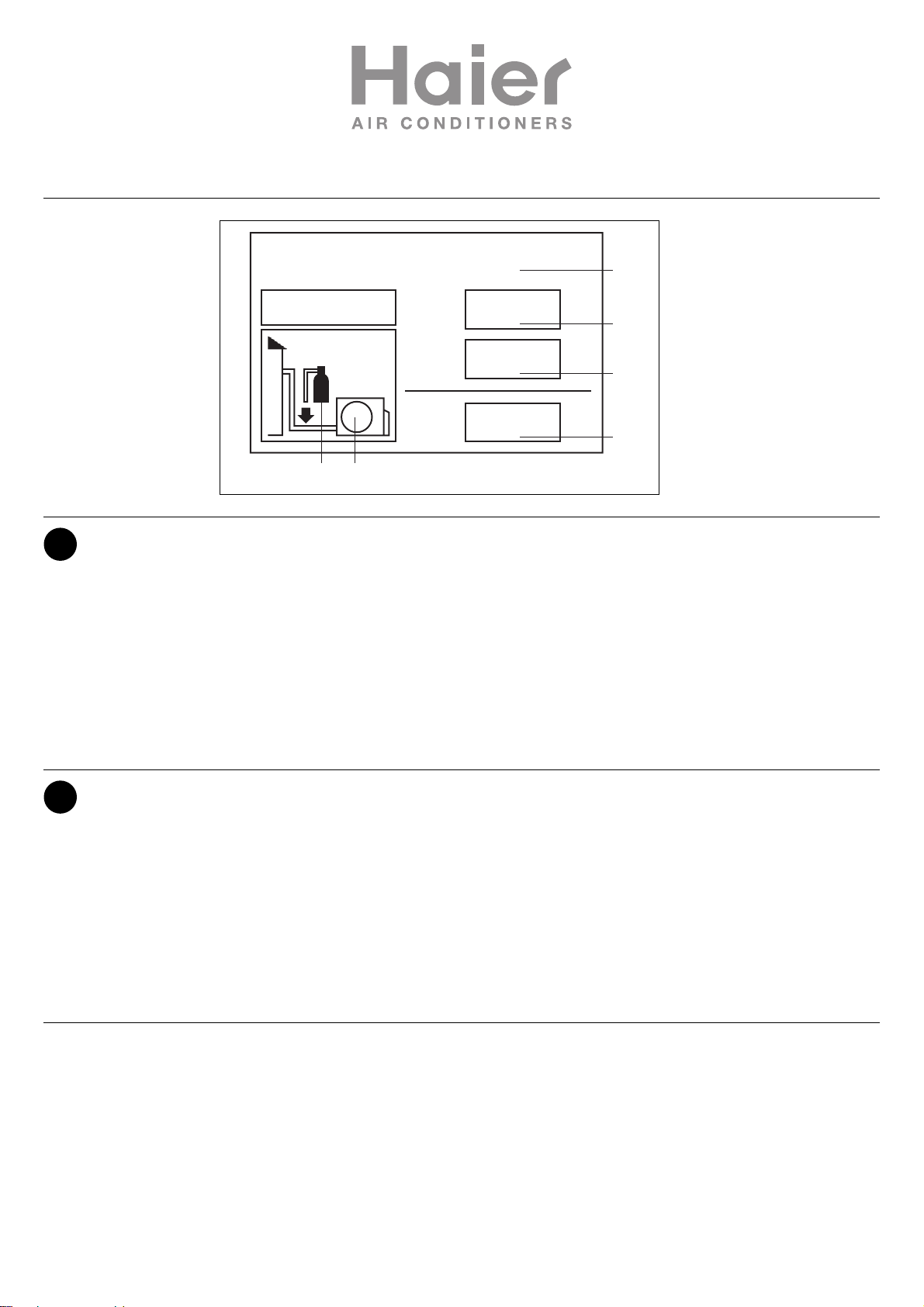
Questo prodotto contiene gas fluorurati ad effetto serra inclusi nel Protocollo
di Kyoto. Non liberare tali gas nell’atmosfera.
Tipo di refrigerante: R410A
Valore GWP*: 1975
*
GWP = potenziale di riscaldamento globale
Compilare con inchiostro indelebile,
• 1 la carica di refrigerante di fabbrica del prodotto
• 2 la quantità di refrigerante aggiuntiva nel campo e
• 1+2 la carica di refrigerante totale
sull’etichetta di carica del refrigerante fornita con il prodotto
L’etichetta compilata deve essere collocata in prossimità della portata di carica del prodotto (ad esempio, nell’interno del coperchio della valvola d’intercettazione).
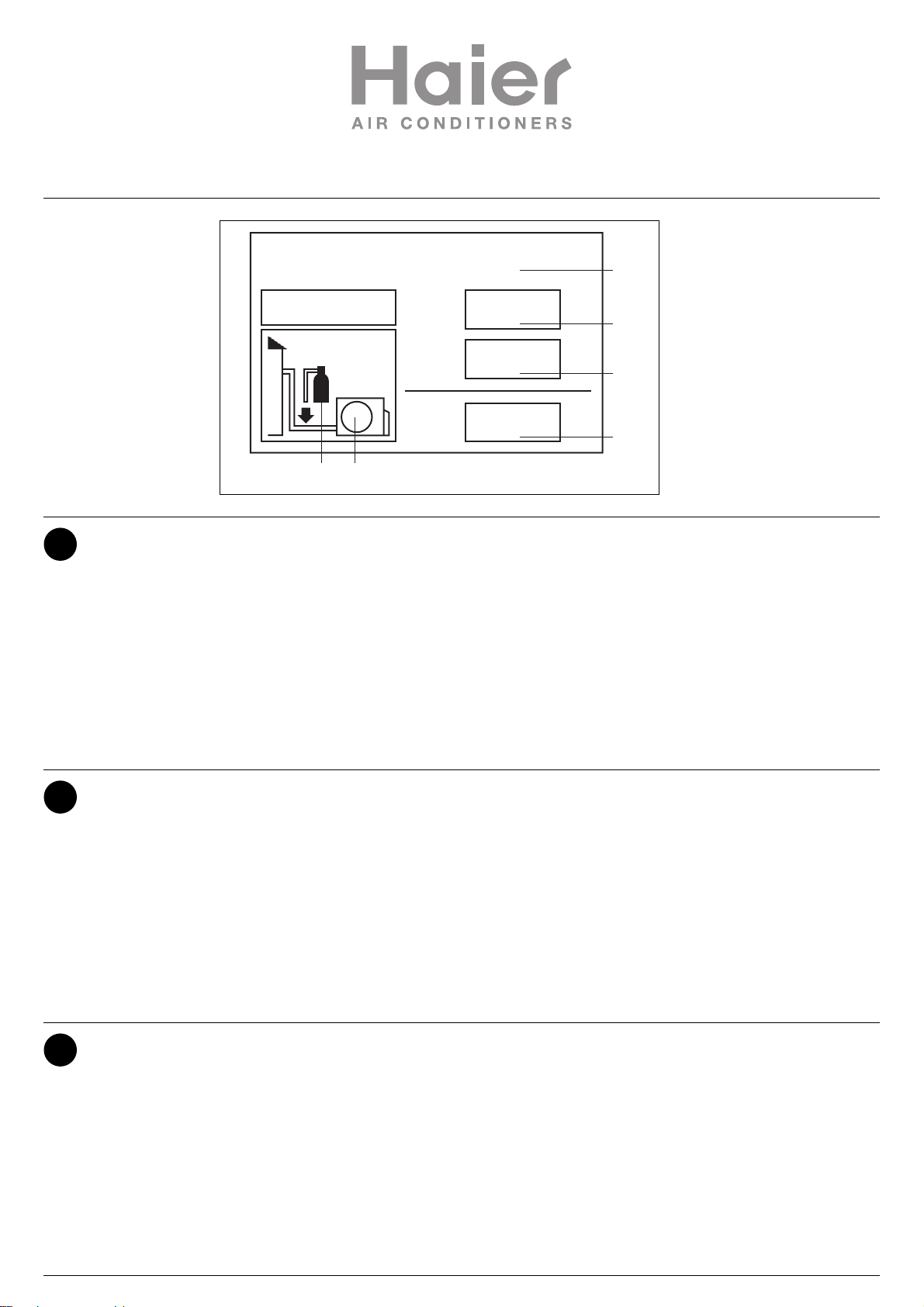
A contiene gas fluorurati ad effetto serra inclusi nel protocollo di Kyoto
B carica di refrigerante di fabbrica del prodotto: vedi targhetta con il nome
dell’unità
C quantità di refrigerante aggiuntiva nel campo
D carica di refrigerante totale
E unità esterna
F cilindro del refrigerante e collettore di carica
INFORMAZIONI IMPORTANTI SUL REFRIGERANTE UTILIZZATO
Haier Industrial Park, No.1 Haier Road, Qingdao, P.R.China
This product contains fluorinated greenhouse gases covered by the Kyoto
Protocol. Do not vent into the atmosphere.
Refrigerant type: R410A
GWP* value: 1975
*
GWP = global warming potential
Please fill in with indelible ink,
• 1 the factory refrigerant charge of the product
• 2 the additional refrigerant amount charged in the field and
• 1+2 the total refrigerant charge
on the refrigerant charge label supplied with the product.
The filled out label must be adhered in the proximity of the product charging
port (e.g. onto the inside of the stop valve cover).
A contains fluorinated greenhouse gases covered by the Kyoto Protocol
B factory refrigerant charge of the product: see unit name plate
C additional refrigerant amount charged in the field
D total refrigerant charge
E outdoor unit
F refrigerant cylinder and manifold for charging
IT
IMPORTANT INFORMATION REGARDING THE REFRIGERANT USED
EN
Ce produit contient des gaz à effet de serre fluorés encadrés par le protocole de Kyoto. Ne pas laisser les gaz s’échapper dans l’atmosphère.
Type de réfrigérant: R410A
Valeur GWP*: 1975
*
GWP = potentiel de réchauffement global
Prière de compléter à l’encre indélébile,
• 1 la charge de réfrigérant d’usine du produit
• 2 la quantité de réfrigérant supplémentaire chargée sur place et
• 1+2 la charge de réfrigérant totale
sur l’étiquette de charge de réfrigérant fournie avec le produit.
L’étiquette complétée doit être apposée à proximité de l’orifice de recharge
du produit (par ex. à l’intérieur du couvercle de la vanne d’arrêt).
A contient des gaz à effet de serre fluorés encadrés par le protocole de
Kyoto
B charge de réfrigérant d’usine du produit: voir plaquette signalétique de
l’unité
C quantité de réfrigérant supplémentaire chargée sur place
D charge de réfrigérant totale
E unité extérieure
F cylindre de réfrigérant et collecteur de recharge
INFORMATION IMPORTANTE RELATIVE AU RÉFRIGÉRANT UTILISÉ
FR
Contains fluorinated greenhouse gases
covered by the Kyoto Protocol
A
R410A
2
1=
2=
1
1+2=
FE
kg
B
kg
C
kg
D
Page 6
Haier Industrial Park, No.1 Haier Road, Qingdao, P.R.China
Dieses Produkt enthält fluorierte Treibhausgase, die durch das Kyoto-Protokoll abgedeckt werden. Lassen Sie Gase nicht in die Atmosphäre ab.
Kältemitteltyp: R410A
GWP* Wert: 1975
*
GWP = Treibhauspotential
Bitte füllen Sie am Kältemittelbefülletikett, das im Lieferumfang des Gerätes
enthalten ist, mit abriebfester Tinte wie folgt aus:
• 1 die werkseitige Kältemittelbefüllung des Produktes
• 2 die am Montageort befüllte zusätzliche Kältemittelmenge und
• 1+2 die gesamte Kältemittelbefüllung
Das ausgefüllte Etikett muss in der Nähe der Kältemittel-Einfüllöffnung angehängt werden (z. B. auf der Innenseite der Absperrventilabdeckung).
A Enthält fluorierte Treibhausgase, die durch das Kyoto-ProtoKoll abge-
deckt werden
B werkseitige Kältemittelbefüllung des Produktes: siehe Typenschild der
Einheit
C zusätzliche am Montageort befüllen Kältemittelmenge
D gesamte Kältemittelbefüllung
E Außeneinheit
F Kältemittelzylinder und Sammelleitung für die Befüllung
WICHTIGE INFORMATIONEN HINSICHTLICH DES VERWENDETEN KÄLTEMITTELS
DE
Este producto contiene los gases fluorados de efecto invernadora regulados
por el Protocolo de Kioto. No vierta gases a la atmósfera.
Tipo de refrigerante: R410A
Valor GWP*: 1975
*
GWP = Potencial de calentamiento global
Rellene con tinta indeleble,
• 1 la carga de refrigerante de fábrica del producto
• 2 la cantidad adicional de refrigerante cargado en campo y
• 1+2 la carga total de refrigerante
En la etiqueta de carga de refrigerante suministrada con el producto.
La etiqueta rellenada debe pegarse cerca de la conexión de carga del producto (p.ej. en el interior de la cubierta de la válvula de tope).
A Contiene los gases fluorados de efecto invernadora regulados por el
Protocolo de Kioto
B Carga de refrigerante de fábrica del producto: véase placa de especifi-
caciones técnicas de la unidad
C Cantidad adicional de refrigerante cargado en campo
D Carga total de refrigerante
E Unidad exterior
F Cilindro del refrigerante y dosificador de carga
INFORMACIÓN IMPORTANTE EN RELACIÓN AL REFRIGERANTE UTILIZADO
ES
Contains fluorinated greenhouse gases
covered by the Kyoto Protocol
A
R410A
2
1=
2=
kg
kg
1
1+2=
FE
kg
B
C
D
Page 7
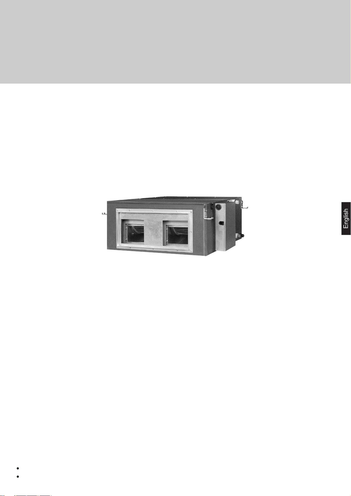
DUCT TYPE AIR CONDITIONER
Operation manual
Installation manual
On-Off Inverter
AD282AHEAA
AD362AHEAA
AD482AHEAA
AD602AHEAA
AD362AHERA
AD482AHERA
AD602AHERA
Please read this operation manual before using the air conditioner.
Please keep this manual carefully and safely.
Page 8

Contents
Cautions
Safety Precautions
Parts and Functions
Operation
Heating Mode
Care and Maintenance
Troubleshooting
Precaution for Installation
Is The Unit Installed Correctly
Installation Procedure
3
4
6
9
12
13
14
18
19
20
2
Page 9
Cautions
Disposal of the old air conditioner
Before disposing an old air conditioner that goes out of use, please make sure it's inoperative and safe. Unplug the air conditioner
in order to avoid the risk of child entrapment.
It must be noticed that air conditioner system contains refrigerants, which require specialized waste disposal. The valuable
materials contained in a air conditioner can be recycled. Contact your local waste disposal center for proper disposal of an old
air conditioner and contact your local authority or your dealer if you have any question. Please ensure that the pipework of your
air conditioner does not get damaged prior to being picked up by the relevant waste disposal center, and contribute to environmental
awareness by insisting on an appropriate, anti-pollution method of disposal.
Disposal of the packaging of your new air conditioner
All the packaging materials employed in the package of your new air conditioner may be disposed without any danger to the
environment.
The cardboard box may be broken or cut into smaller pieces and given to a waste paper disposal service. The wrapping bag
made of polyethylene and the polyethylene foam pads contain no fluorochloric hydrocarbon.
All these valuable materials may be taken to a waste collecting center and used again after adequate recycling.
Consult your local authorities for the name and address of the waste materials collecting centers and waste paper disposal
services nearest to your house.
Safety Instructions and Warnings
Before starting the air conditioner, read the information given in the User's Guide carefully. The User's Guide contains very
important observations relating to the assembly, operation and maintenance of the air conditioner.
The manufacturer does not accept responsibility for any damages that may arise due to non-observation of the following
instruction.
Damaged air conditioners are not to be put into operation. In case of doubt, consult your supplier.
Use of the air conditioner is to be carried out in strict compliance with the relative instructions set forth in the User's Guide.
Installation shall be done by professional people, don't install unit by yourself.
For the purpose of safety, the air conditioner must be properly grounded in accordance with specifications.
Always remember to unplug the air conditioner before opening inlet grill. Never unplug your air conditioner by pulling on
the power cord. Always grip plug firmly and pull straight out from the outlet.
All electrical repairs must be carried out by qualified electricians. Inadequate repairs may result in a major source of
danger for the user of the air conditoiner.
Do not damage any parts of the air conditioner that carry refrigerant by piercing or perforating the air conditioner's tubes
with sharp or pointed items, crushing or twisting any tubes, or scraping the coatings off the surfaces. If the refrigerant
spurts out and gets into eyes, it may result in serious eye injuries.
Do not obstruct or cover the ventilation grille of the air conditioner. Do not put fingers or any other things into the inlet/outlet
and swing louver.
Do not allow children to play with the air conditioner. In no case should children be allowed to sit on the outdoor unit.
3
Page 10
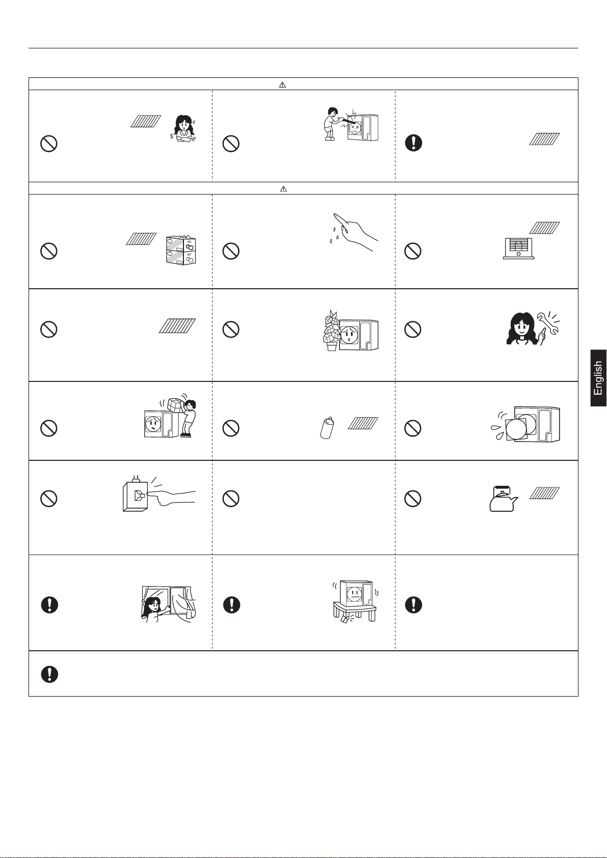
Safety Precautions
Before starting to use the system, read carefully this "SAFETY PRECAUTIONS" to ensure a proper operation of the system.
Safety precautions described here are classified to " WARNING" and " CAUTION". Precautions which are shown
in the column of " WANING" means that an improper handing could lead to a grave result like a death, serious injury,
etc. However, even if precautions are shown in the column of " CAUTION", a very serious problem could occur depending
on situation. Make sure to observe these safety precautions faithfully because they are very important information to ensure
the safety.
Symbols which appear frequently in the text have following meanings.
Strictly prohibited.
Observe instructions faithfully.
Provide a positive grounding.
When you have read through the manual, keep it always at hand for read consultation. If the operator is replaced, make
sure to hand over this manual to the new operator.
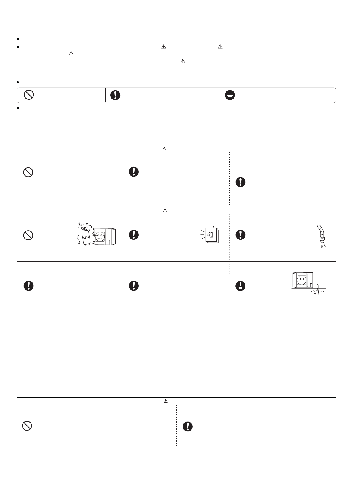
CAUTIONS FOR INSTALLATION
WARNING
The system should be applied to places as office,
restaurant, residence and the like.
Application to inferior environment such as an
engineering shop, could cause equipment
malfunction and serious injury or death.
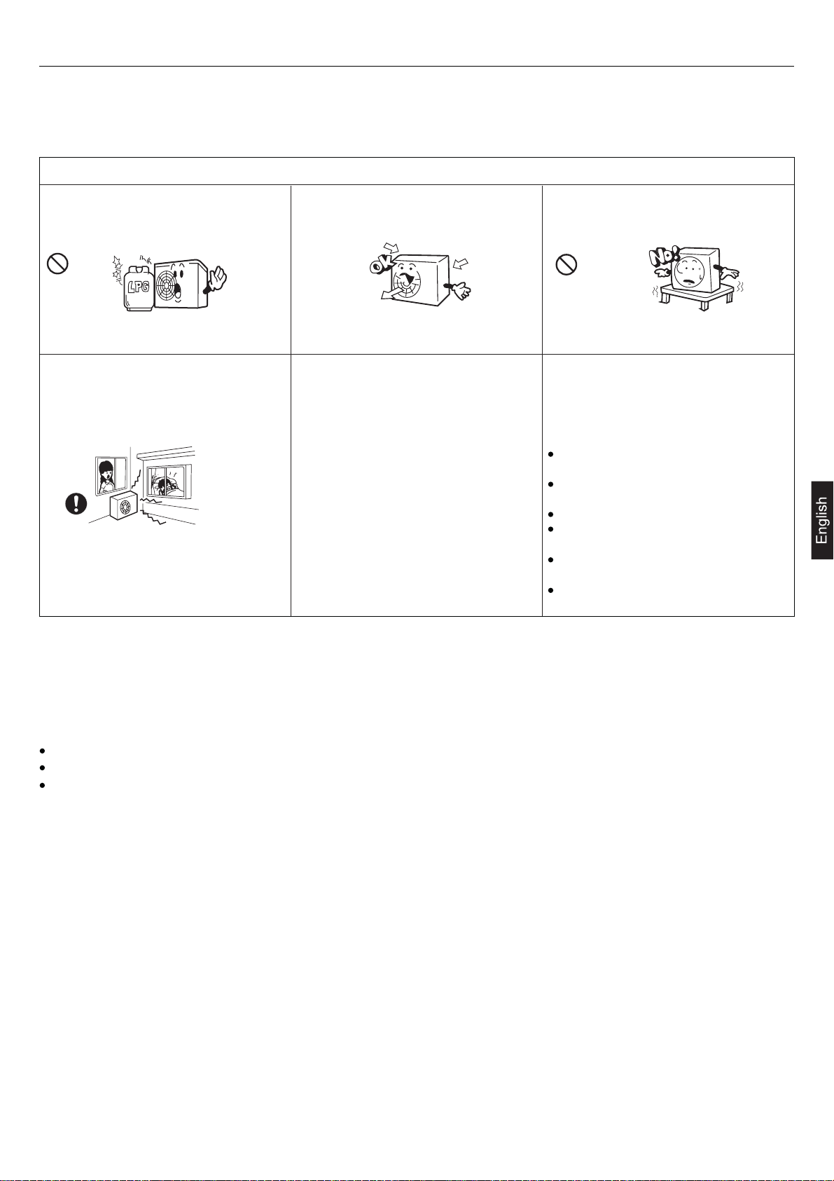
Do not install nearby the place where may have
leakage of flammable gas.
If the gas leakes and gathers around, it may cause
the fire.
Where strong winds may prevail, the system
should be fixed securely to prevent a collapse.
The system should be installed by your dealer or
a professional installer.
Installation by yourself is not encouraged because
it could cause such problems as water leakage,
electrical shock or fire accident by some improper
handing.
CAUTION
Depending on the place of installation, a circuit
breaker may be necessary.
ON
OFF
Unless the circuit breaker is installed, it could cause
elecrical shocks.
Install on the place where can endure the weight
of air conditioner.
When you need some optional devices such as a
humidifier, electric heater, etc., be sure to use the products
which are recommended by us. These devices should
be attached by a professional installer.
Installation by yourself is not encouraged because it could
cause such problems as water leakage, electrical shock
or fire accident by some improper handing.
Drain pipe should be arranged to provide a positive
draining.
If the pipe is arranged improperly, furniture or the
likes may be damaged by leaked water.
Make sure the system is grounded.
Bodily injury could result by a collapse. Bodily injury could result by a careless installation. Grounding cable should never be connected to
a gas pipe, city water pipe, lightning conductor
rod or grounding cable of telephone. If the
grounding cable is not set properly, it could cause
electric shocks.
CAUTIONS FOR TRANSFER OR REPAIR
WARNING
Modification of the system is strictly prohibited. When the system needs a
repair, consult your dealer.
Improper practice of repair could cause water leakage, electric shock or
fire.
When the air conditioner is relocated, contact your dealer or a professional
installer.
Improper practice of installation could cause water leakage, electric shock
or fire.
4
Page 11
Safety Precautions
CAUTIONS FOR OPERATION
You should refrain from exposing your body directly
to cool wind for a long time.
WARNING
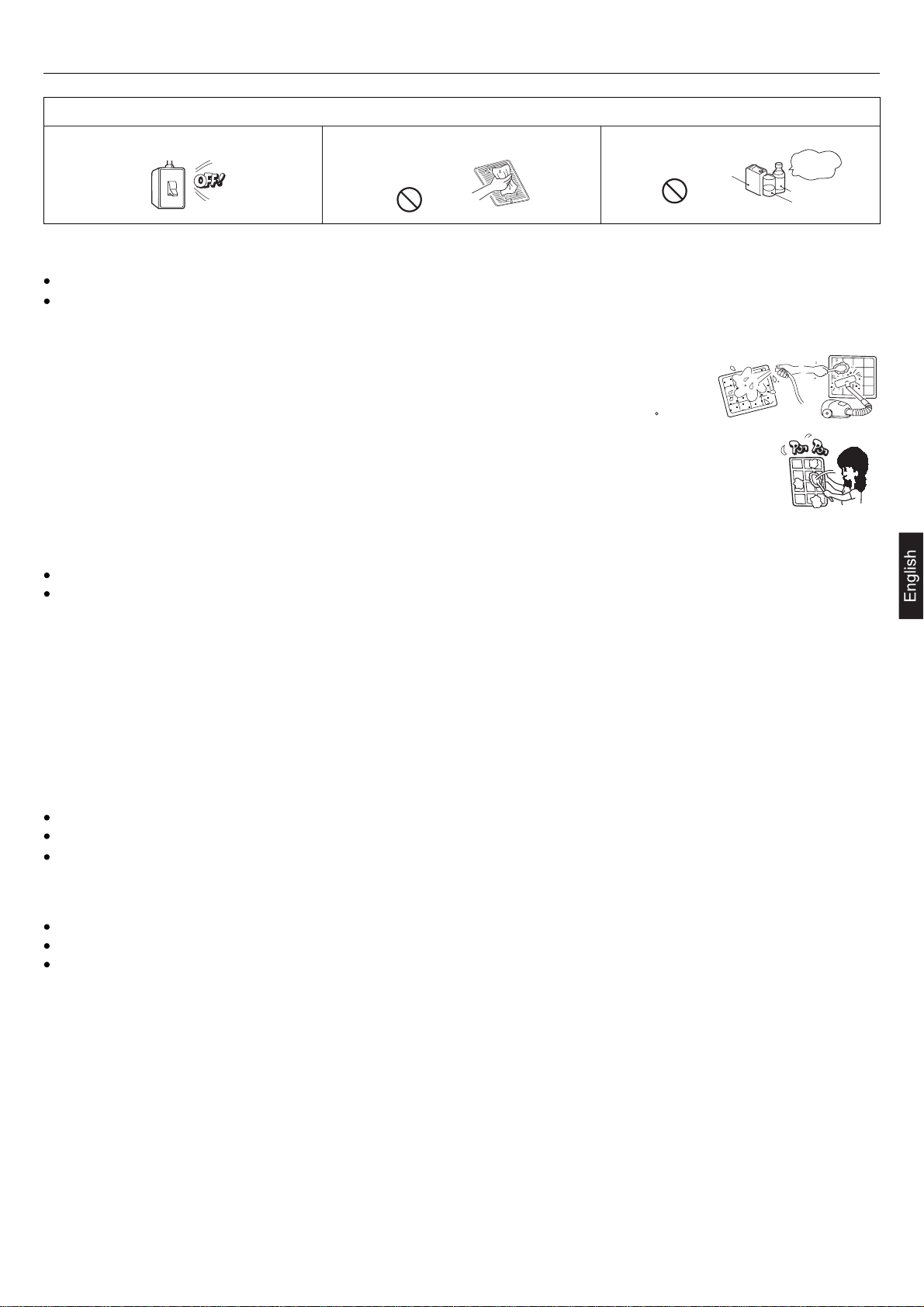
Do not poke the air inlet or outlet with a bar, etc. When any abnormal condition (scorching smell or
others) is found, stop the operation immediately
and turn off the power switch. Then consult your
dealer.
It could affect your physical condition or cause
some health problems.
The system should never be used for any other
purposes than intended such as for preservation
of food, flora and fauna, precision devices or work
of art.
problems.
Do not wash the air conditioner with water.
It could cause electric shocks. It will not be good for their health. Use of steel or copper wire in place of a fuse is
Neither stand on the air conditioner nor
place something on it.
object.
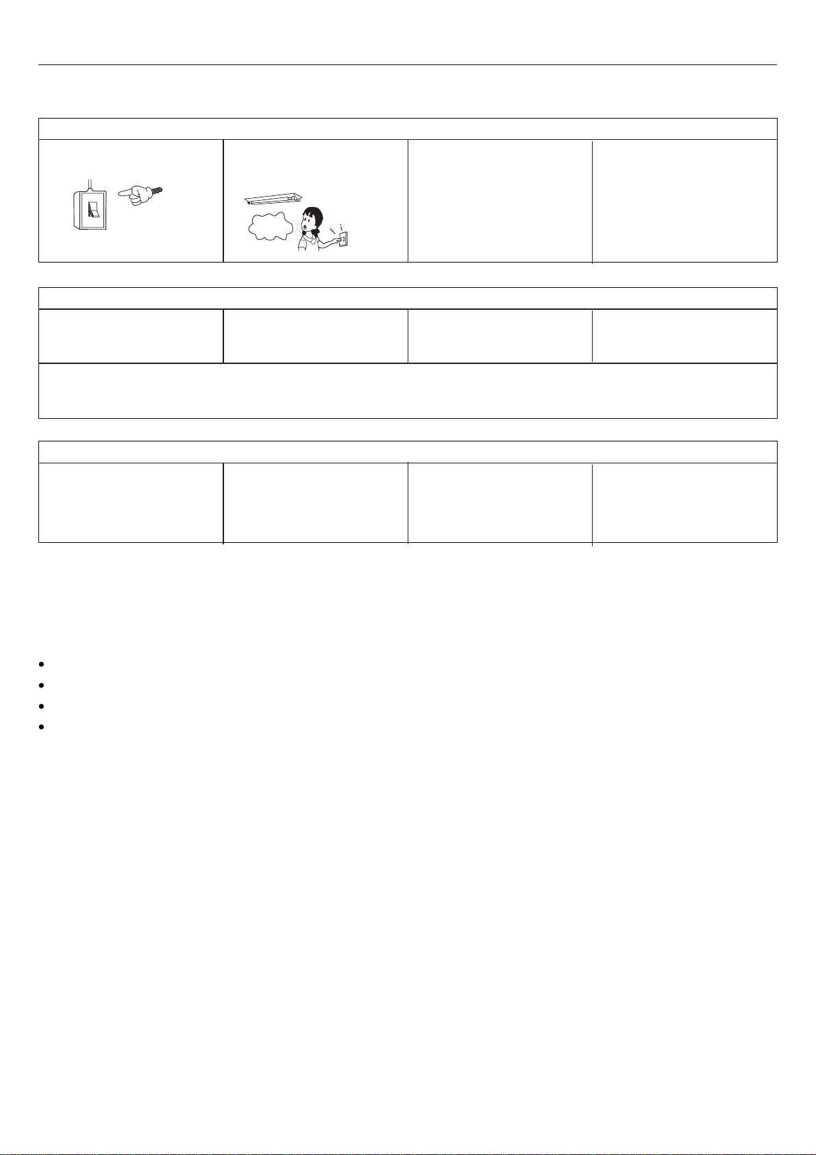
Do not use the power switch to turn on or off the
system.
It could cause a fire or water leakage. There is a risk of injury. If the system is operated at the vicinity of such
When operating the system simultaneously with
a combustion apparatus, indoor air must be
ventilated frequently.
ON
OFF
Since the internal fan is operating with a high
speed, it could cause an injury.
CAUTION
Do not handle switches with a wet hand. Combustion apparatus should not be placed
It could cause electric shocks.It could cause deterioration of food or other
Do not install the system where the air outlet
reaches directly the flora and fauna.
It is strictly prohibited to place a container of
combustible gas or liquid near the air conditioner
or to spray it directly with the gas or liquid.
Do not touch the air outlet section while the swing
louver is operating.
Check occasionally the support structure of the
unit for any damage after a use of long period of
time.
If you continue the operation without removing the
cause, it could result in a trouble, electric shock
or fire.
allowing a direct exposure to wind of air conditioner.
Incomplete combustion could occur on the
apparatus.
Make sure to use a fuse of proper electric rating.
strictly prohibited because it could result in a trouble
or fire accident.
Do not operate the system while the air outlet grill
is removed.
There is a risk of injury.It could cause a fire accident.There are risks of falling or injury by collapsed
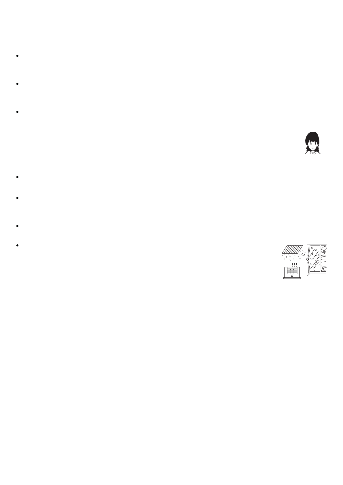
Do not use such equipment as a water heater, etc.
around the indoor unit or the wire controller.
equipment which generates steam, condensed
water may drip during cooling operation or it could
cause a fault current or short-circuit.
When cleaning the system, stop the operation and
turn off the power switch.
Insufficient ventilation could cause an oxygen
deficiency accident.
Do not put water containers on the unit such as a flower vase, etc.
If the water enters into the unit and damages the electric insulation material, it may cause electric shock.
If the structure is not repaired immediately, the
unit could topple down to cause a personal injury.
Cleaning should never be done while the internal
fans are running with high speed.
5
Page 12
Safety Precautions
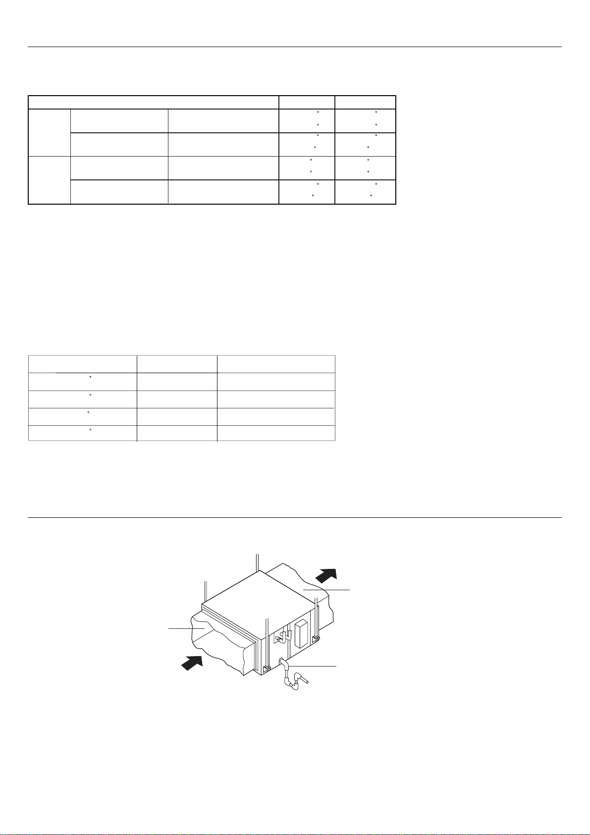
The machine is adaptive in following situation
1. Applicable ambient temperature range:
ON-OFF Inverter
Cooling
Heating
2. If the supply cord is damaged, it must be replaced by the manufacturer or its service agent or a similar qualified person.
3. If the fuse on PC board is broken, please change it with the type of T 3.15A /250VAC.
4. The wiring method should be in line with the local wiring standard.
5. The power cable and connecting cable are self-provided.
The connecting cable should be H05RN-F 4G 0.75mm
All the cables shall have got the European authentication certificate. During installation, when the connecting cables
break off, it must be assured that the grouding wire is the last one to be broken off.
6. The breaker of the air conditioner should be all-pole switch, and the distance between its two contacts should be no
less than 3mm.
7. The indoor unit installation height is at least 2.5m.
8. In order to obtain the Unit's best performances, the fan speed is recommended according to the following conditions.
Indoor temperature
Outdoor temperature
Indoor temperature
Outdoor temperature
max. DB/WB
min. DB/WB
max. DB/WB
min. DB/WB
max. DB/WB
min. DB/WB
max. DB/WB
min. DB/WB
32/23 C
18/14 C
43/26 C
10/6 C
24/18 C
-7 C
2
.
27 C
15 C
32/23 C
18/14 C
43/26 C
-5 C
27 C
15 C
24/18 C
-7 C
outdoor ambient temp.
> 40 C
< 20 C
< -5 C
> 18 C
operation mode
cooling
cooling
heating
heating
Parts and Functions
Indoor Unit
Duct
recommended fan speed
low
high
low
high
Air outlet
Duct
Air inlet
Drain pipe
6
Page 13
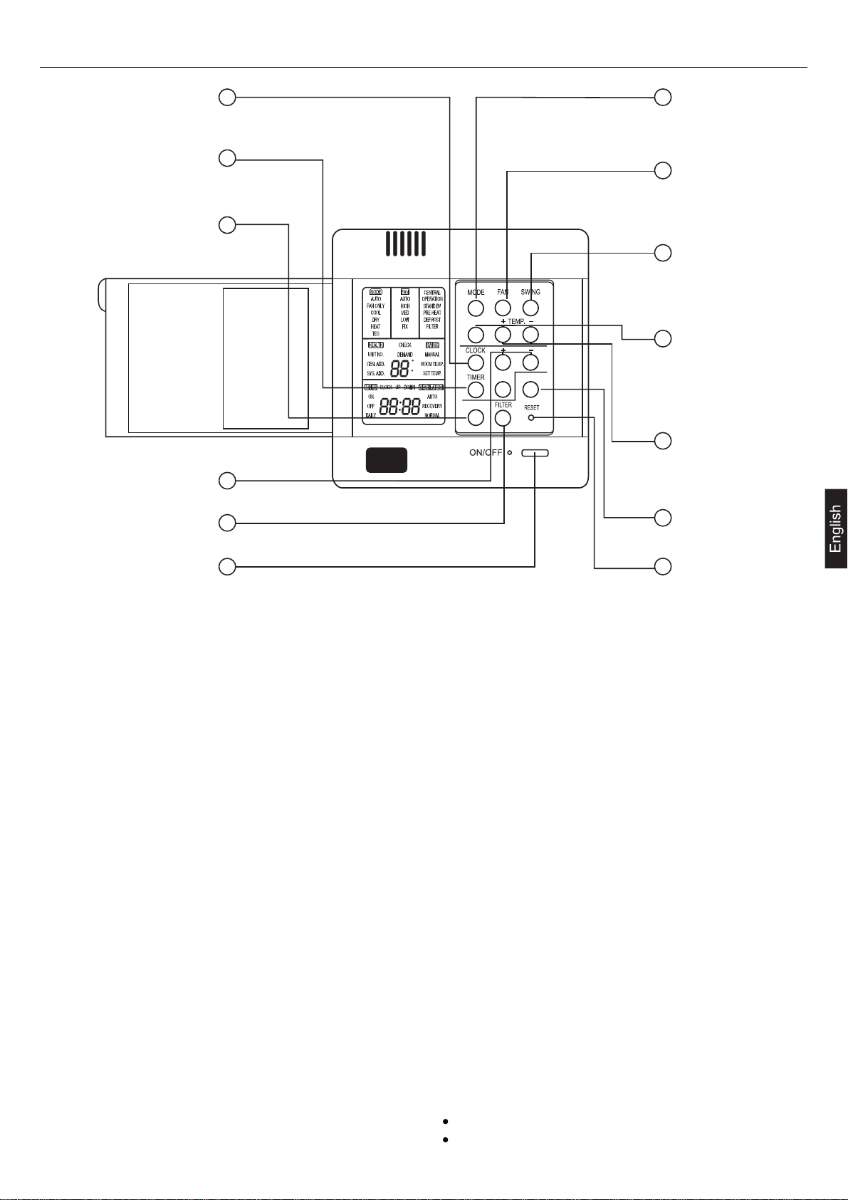
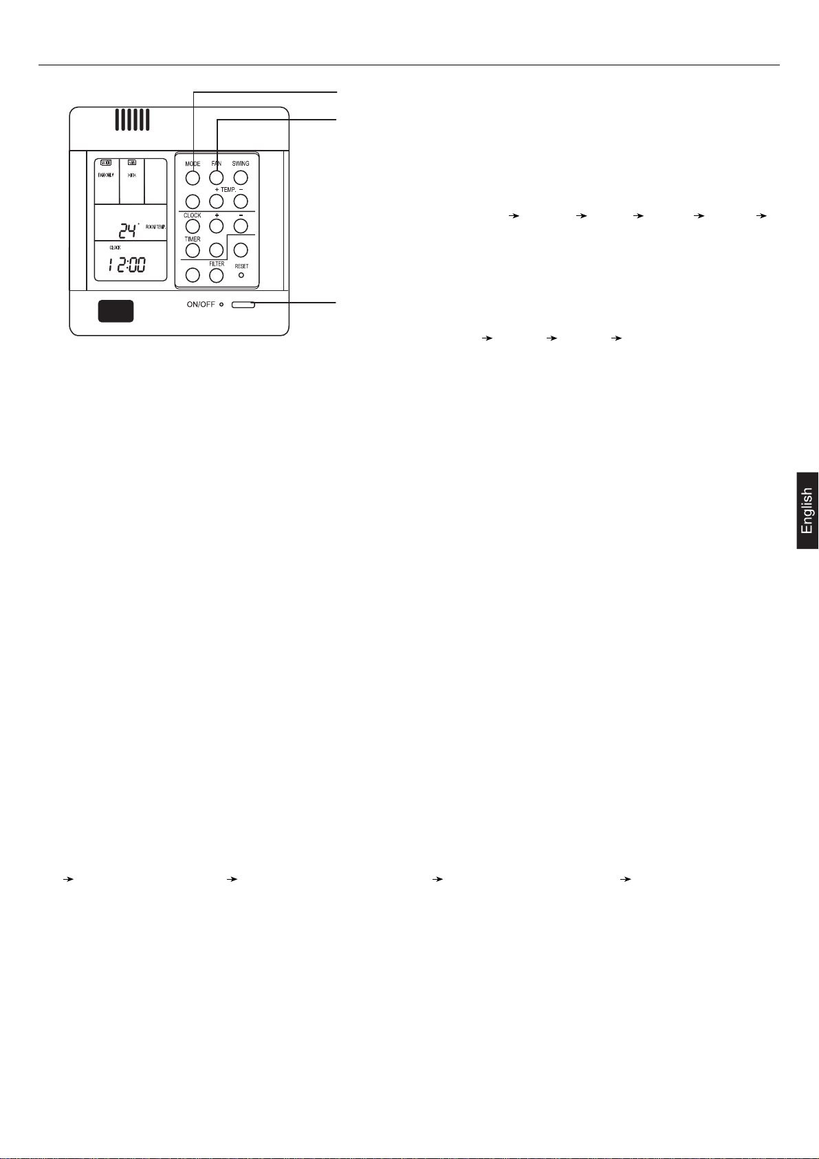
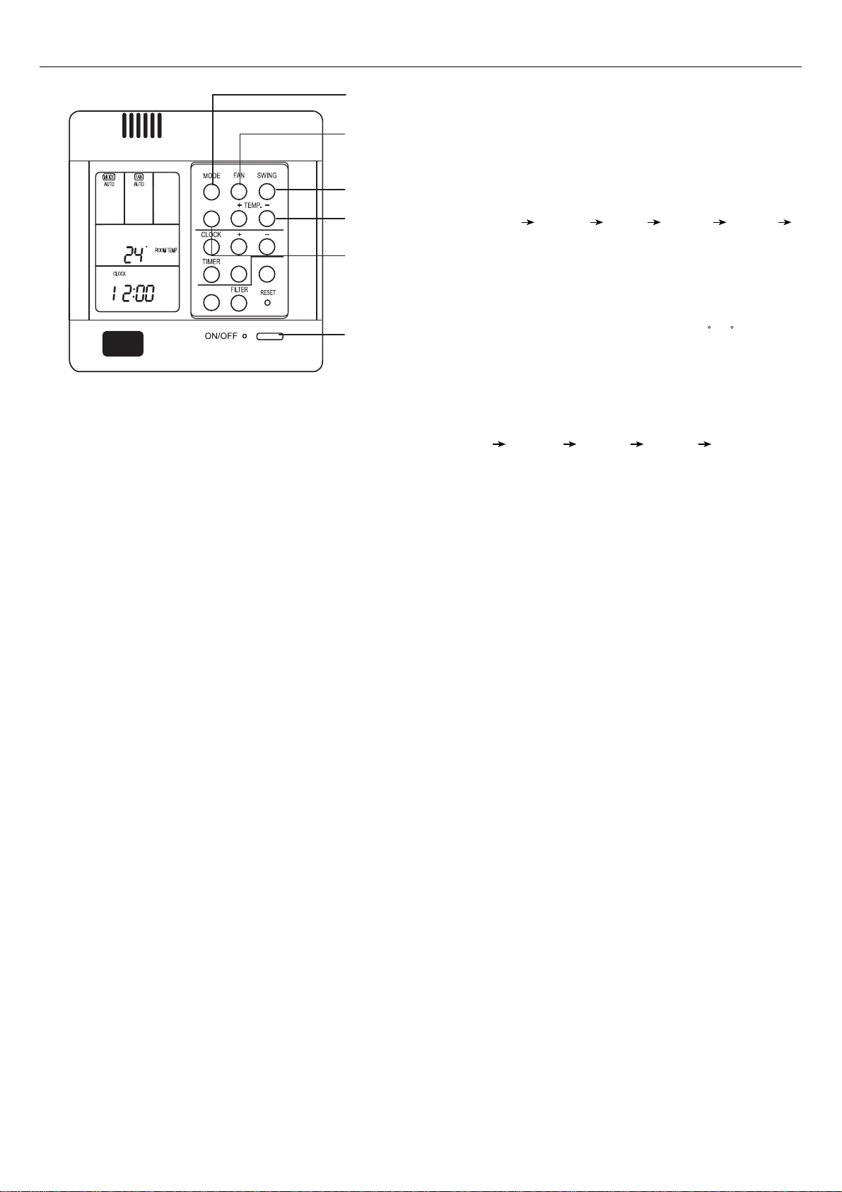
Parts and Functions
1
2
3
HEALTH
C
F
4
SET RECOVERY
CHECK
7
8
9
10
11
5
6
1.CLOCK button
Used to adjust time.
2.TIMER button
Used to set timer mode.
3.CHECK button
Auto-diagnostic button.
4.+ and - button
Stands for time plus/minus, used to adjust time.
5.FILTER button
Filter-cleaned button.
6.POWER ON/OFF button
Used for unit to start and stop.
12
13
8.FAN button
Used to select indoor air flow.
9.SWING button
Used for setting indoor swing mode.
10.HEALTH button
Used for setting indoor health function.
11.TEMP + and - button
Used for changing set temperature.
12.RECOVERY button
used to switch over air-exchanging mode.
13.RESET button
Reset correct mode button.
7.MODE button
Used to select indoor operation mode.
Note:
The above information is the explanation of the displayed
information. Therefore it varieswith those displayed in
actual operation.
Cautions:
On cooling only unit, heating mode is not available.
The functions 5,9,10 are not available for these units.
7
Page 14
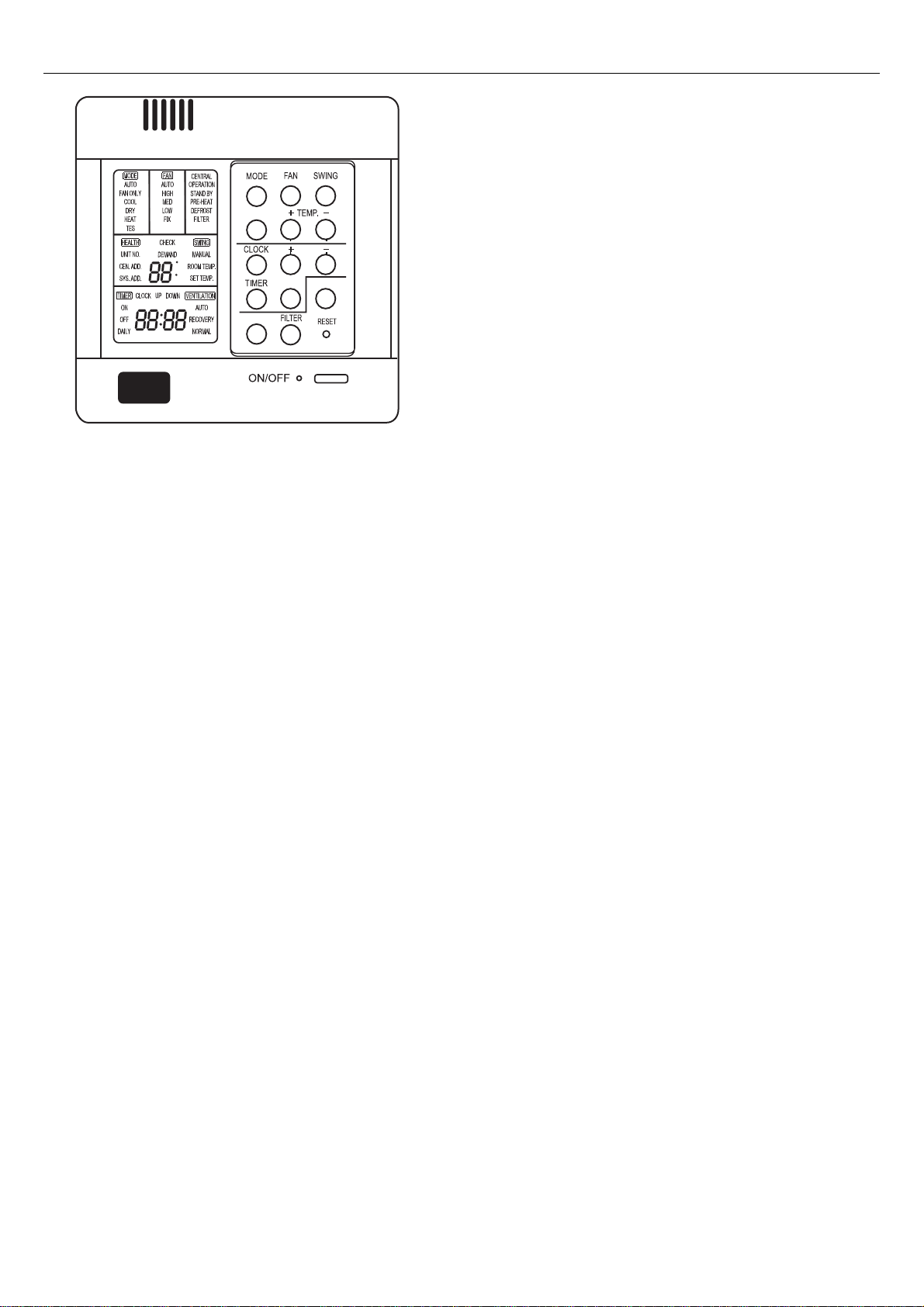
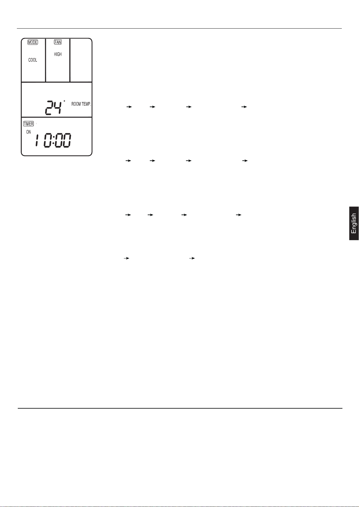
Parts and Functions
HEALTH
C
F
SET RECOVERY
CHECK
[MODE]
[AUTO]:Auto operation mode.
[FAN ONLY]:Air-throwing mode.
[COOL]:Cooling operation mode.
[DRY]:Dehumidification mode.
[HEAT]:Heating operation mode.
[TES]:In heating mode, auxiliary electric heater is running.
Only when the unit with auxiliary electric heater is in
auxiliary electric heating mode, it will display.
[FAN]
[AUTO]:Auto fan running.
[HIGH]:High fan speed.
[MED]:Medium fan speed.
[LOW]:Low fan speed.
[FIX]:Fixed fan speed, it will display only when fixed fan
speed is requested to main indoor unit.
[CENTRAL]:Central control mode.
[OPERATION]:Running mode.
[STAND BY]: Waiting mode.
[PRE-HEAT]: Pre-heating mode.
[DEFROST]: Defrosting mode.
[FILTER]: Request of filter to be cleaned.
[HEALTH]:Health function.
[CEN.ADD]:Central control address, the address number
will display on "88".
[SYS.ADD.]:System address, the address number will
display on "88".
[CHECK]:Auto-diagnostic, trouble shooting.
[DEMAND]:Compulsory operation function, when it works,
[CENTRAL] will flash.
[SWING][MANUAL]:Swing mode.
[ROOM TEMP.]:Indoor ambient temperature.
[SET TEMP.]:Set admired temperature.
[TIMER]
[ON]:Timer function is on.
[OFF] :Timer function is off.
[ON][OFF] :Timer function is ON-OFF.
[ON][OFF][DAILY]:Timer ON-OFF will switch over in turn
daily.
[CLOCK]:Clock display, the displaying time is the current
time of the clock.
[UP],[DOWN]:Indicator of filter elevating.
[VENTILATION]
[AUTO]:Auto ventilation mode.
[NORMAL]:Normal ventilation mode.
[RECOVERY]:Fully heat exchanging ventilation mode.
8
Page 15
Operation
Fan Only
2
(1)Start up operation:
Press the ON/OFF button. The system will start up and the
3
display will be on LCD.
(2)Select operation mode :
HEALTH
Press the MODE button. Each press, operation mode in
the [MODE] display section changes as follows:
C
SET RECOVERY
[FAN ONLY] [COOL] [DRY] [HEAT] [AUTO]
[FAN ONLY].
Select [FAN ONLY].
CHECK
(3)Select fan speed:
1, 4
Press the FAN button. Each press, fan speed in the [FAN]
display section changes as follows:
[HIGH] [MED] [LOW] [HIGH].
Select proper fan speed.
(4)Power off:
Press the ON/OFF button. Indoor unit will be powered off,
and there are only the time and the ambient temperature
in the screen.
VENTILATION mode
(only for the unit with fresh air function or heat recovery function)
Press the RECOVERY button, then the unit will switch over the ventilation mode:
[ ] [VENTILATION][AUTO] [VENTILATION][RECOVERY] [VENTILATION][NORMAL] [ ]
Please select appropriate ventilation mode.
9
Page 16
Operation
Auto, Cool, Heat and Dry
2
(1) Start up operation:
Press the ON/OFF button. The system will start up and the
4
display will be on LCD.
(2) Select operation mode:
5
HEALTH
3
C
SET RECOVERY
CHECK
6
Press the MODE button. Each press, operation mode in
the [MODE] display section changes as follows:
[FAN ONLY] [COOL] [DRY] [HEAT] [AUTO]
[FAN ONLY].
Select operation mode ([COOL],[DRY],[HEAT],or [AUTO]).
(3) Set temperature:
Press the TEMP + or - button. Each press, setting
1, 7
temperature will increase or decrease by 1 C ( F). [SET
TEMP.] appears on the display.
(4) Select fan speed:
Press the FAN button. Each press, fan speed in the [FAN]
display section changes as follows:
[AUTO] [HIGH] [MED] [LOW] [AUTO].
Select proper fan speed.
(5) Select SWING function:
Press the SWING button once, [SWING] will display and
swing function is valid. Press again, [SWING] will disappear
and swing function is invalid.
(6) Set HEALTH operation:
Press the HEALTH button to set the indoor health function.
Press it once, [HEALTH] will display in the display section,
and indoor health function is valid. Press it again, [HEALTH]
will disappear, and the health function is invalid. This function
is valid only for the unit with health function.
(7) Power off:
Press the ON/OFF button. Indoor unit will be powered off,
and there are only the time and the ambient temperature
in the screen.
10
Page 17
Operation
C
Timer Function
Clock set
Before setting timer mode, set the clock to the correct time.
Press the CLOCK button. "CLOCK" will begin flashing at the frequency of 2Hz. Press
the clock +/- button to adjust the current time. Then press the SET button to confirm
until the proper time comes.
TIMER ON operation:
Press the TIMER button. Each time the button is pressed, TIMER mode in the [TIMER]
display section changes as follows:
[ON] [OFF] [ON][OFF] [ON][OFF][DAILY] [ ].
Select [TIMER] [ON], and then [TIMER] [ON] flashes. Press the clock +/- button to adjust
the time of TIMER ON, and press the SET button to confirm.
TIMER OFF operation:
Press the TIMER button. Each time the button is pressed, TIMER mode in the [TIMER]
display section changes as follows:
[ON] [OFF] [ON][OFF] [ON][OFF][DAILY] [ ].
Select [TIMER] [OFF], and then [TIMER] [OFF] flashes. Press the clock +/- button to
adjust the time of TIMER OFF, and press the SET button to confirm.
TIMER ON-OFF operation:
Press the TIMER button. Each time the button is pressed, TIMER mode in the [TIMER]
display section changes as follows:
[ON] [OFF] [ON][OFF] [ON][OFF][DAILY] [ ].
Select [TIMER] [ON] [OFF], and then [TIMER][ON] flashes. Press the clock +/- button to
adjust the time of TIMER ON, and then press the TIMER button to confirm. [TIMER][ON]
will be constant on and [TIMER] [OFF] flashes.
Press the clock +/- button to adjust the time of TIMER OFF, and press the SET button to
confirm. The time sequence of timer on and timer off will determine the mode is [TIMER]
[ON] [OFF] or [TIMER] [OFF] [ON]. If you want the current time, press the CLOCK button
once, current time will display; Press again, [CLOCK] will flash, and press clock + / - button
to adjust the time.
Note:
1.
If the two times are the same, the timer state which is set later will flash, in this case,
timer can not be set.
When entering TIMER setting state, if you do not input any button in continuous 10
2.
seconds, the unit will quit from the TIMER mode.
Cancel TIMER operation:
In the timer operation state, press the TIMER button, the unit will quit from the current
timer operation state, and the set data will be memorized, then enter the next timer
mode. When [TIMER] does not display, the timer will be cancelled.
Operation
Query indoor malfunction history:
In the state of power on or power off, press the CHECK button to enter the malfunction-querying mode of all indoor units
in the group. Then [CHECK] and [UNIT NO.] will display, and the actual indoor numbers will be displayed in some sequence
(unit number is in decimals). At the same time, in the time region, there will be the current malfunction and the latest time
malfunction, the displaying format is [XX:YY], in which XX stands for the current malfunction, if normal, it will display "--";
YY stands for the latest time malfunction. The failure code of every unit will display for 3 seconds. After the failure codes
of all indoor units in the whole group are displayed, the mode will quit automatically.
11
Page 18
Heating Mode
"HOT KEEP" function
"HOT KEEP"is operated in the following cases.
When heating is started:
In order to prevent blowing out of cool wind, the indoor unit fan stopped according to the room temperature which heating
operation is started. Wait for approx. 2 to 3 minute, and the operation will be automatically changed to the ordinary heating
mode.
Defrosting operation (in the heating mode):
When it is liable to frost, the heating operation is stopped automatically for 5 to 12 minutes once per approx. one hour,
and defrosting is operated. After defrosting is completed, operation mode is automatically changed to ordinary heating
operation.
When the room thermostat is actuated:
When room temperature increases and room temperature controller actuates, the fan speed is automatically changed to
stop under low temperature condition of indoor heat exchanger. When room temperature decreases, air conditioner
automatically changes over to ordinary heating operation.
Warming Operation
Heat pump type warming
With the heat pump type warming, the mechanism of heat pump that concentrate heat of outdoor air with the help of
refrigerant to warm the indoor space, is utilized.
Defrosting operation
When a room is warmed with a heat pump type air conditioner, frost accumulates on the heat exchanger of outdoor unit
along with the drop of indoor temperature. Since the accumulated frost reduces the effect of warming, it is necessery to
automatically switch the operation to the defrosting mode. During the defrosting operation, heating operation is interrupted.
Atmospheric temperature and warming capacity
Warming capacity of heat pump type air conditioner decreases along with the drop of outdoor temperature. When the
warming capacity is not sufficient, it is recommended to use another heating implement.
Period of warm-up
Since the heat pump type air conditioner employs a method to circulate warm winds to warm
the entire space of a room, it takes time before the room temperature rises.
It is recommendable to start the operation a little earlier in a very cold morning.
12
Page 19
Care and Maintenance
Points to observe
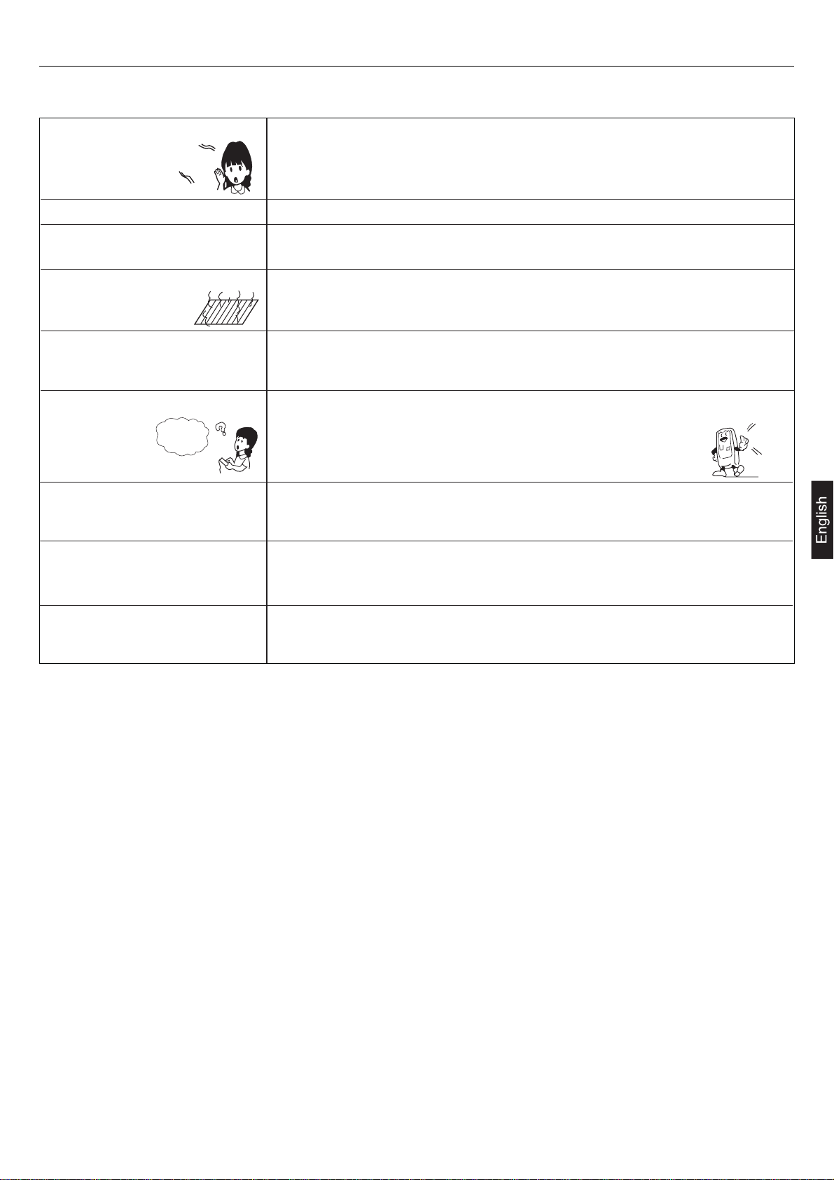
Turn off the power supply switch. Do not touch with wet hand. Do not use hot water or volatile liquid.
Do not
use!
Benzine
Tooth powder
ON
OFF
CAUTION
Do not open the inlet grill until fan stops completely.
Fan will continue rotating for a while by the law of inertia after operation is being stopped.
Cleaning the air filter
1.Clean the air filter by lightly tapping it or with the cleaner. It is more effective to clean
the air filter with water.
If the air filter is very dirty, dissolve neutral detergent in the lukewarm water (approx. 30 C),
rinse the air filter in the water, and thoroughly wash the air filter off the detergent
in the plain water.
2.After drying the air filter, set it up on the air conditioner.
Thinner
CAUTION
Do not dry the air filter with fire.
Do not run the air conditioner without the air filter.
Care and Cleaning of the unit
Clean with soft and dry cloth.
If it is very dirty, dissolve neutral detergent in the lukewarm water and make the cloth wet with the water. After wiping,
clean off the detergent using clean water.
Post-Season Care
Operate the unit with FAN mode on a fair day for about half a day to dry the inside of the unit well.
Stop operation and turn off the power supply switch. Electric power is consumed even the air conditioner is in stop.
Clean the air filter and set it in the place.
Pre-Season Care
See that there are no obstacles blocking the air inlet and air outlet of both indoor and outdoor units.
Make sure that the air filter is not dirty.
Cut in the power supply switch 12 hours before starting run.
13
Page 20
Troubleshooting
Please check the following things about your air conditioner before making a servie call.
Unit fails to start
Is the power source switch
adjust cut in?
ON
OFF
Power supply switch is not
ON.
Is city supply power in normal? Isn't the signal receiving
section exposed to the direct
sunlight or strong illumination?
Power
stoppage?
Cooling or heating is not sufficient
Isn't the earth leakage breaker
in action?
It is dangerous. Turn off the
power supply switch
immediately and contact the
sales dealer.
Is the thermostat adjust as
required?
Isn't the air filter dirty? Isn't any doors or windows
left open?
Doesn't any obstacle exist at
the air inlet or outlet?
Isn't the swing louver horizontal? (At HEATING mode)
If swing louver is horizontal, the blow wind does not reach floor.
Cooling is not sufficient
Isn't sun-shine invading direct? Isn't any unexpected heating
load generated?
Isn't the room much crowded?
The wind does not blow during
heating operation
Isn't it warming up?
When the air conditioner does not operate properly after you have checked the above mentioned items or when the following
phenomenon is observed, stop the operation of the air conditioner and contact your sales dealer.
The fuse or breaker often shuts down.
Water drops off during cooling operation.
There is a irregularity in operation or abnormal sound is audible.
When the CHECK LED1 (red) flickers, an irregularity has occurred in the air conditioner.
14
Page 21
Troubleshooting
The followings are not malfunction
Water flowing sound is heard.
Shuru
Shuru
When the air conditioner is started, when the compressor starts or stops during
operation or when the air conditioner is stopped, it sometimes sounds "shuru shuru"
or "gobo gobo". It is the flowing sound of the refrigerant, and it is not a trouble.
This is caused by heat expansion or contraction of plastics.Cracking sound is heard.
It smells. Air which blows out from the indoor unit sometimes smells. The smell results from
residents of tobacco smoke or cosmetics stuck inside of unit.
During operation, white fog comes
out of indoor unit.
When the air conditioner is used at restaurant etc. where dense edible oil fume is
always exists, white fog sometimes blows out of air outlet during operation. In this
case consult sales dealer for cleaning the heat exchanger.
It is switched into the FAN mode
during cooling.
To prevent frost from being accumulated on the indoor unit heat exchanger, it is
sometimes automatically switched to the FAN mode but it will soon return to the
cooling mode.
The air conditioner can not be
restarted soon
after it stops.
Unit does
not start
Air does not blow or the fan speed
can not be changed during
Even if the operation switch is turned on, cooling, dehumidifying or heating is not
operable for three minutes after the conditioner is stopped. Because the
protecting circuit is activated (During this time air conditioner operates
in fan mode).
Wait for
three
minutes
When it is excessively cooled during dehumidifying, the blower automatically repeats
reducing and lowering the fan speed.
dehumidifyin.
During operation, operation mode
has changed over automatically.
Water or steam generates from
the outdoor unit during heating.
Isn't the AUTO mode selected?
In the case of AUTO mode, operation mode is changed automatically from cooling
to heating or vise-versa according to the room temperature.
This results when frost accumulated on the outdoor unit is removed (during defrosting
operation).
15
Page 22
Troubleshooting
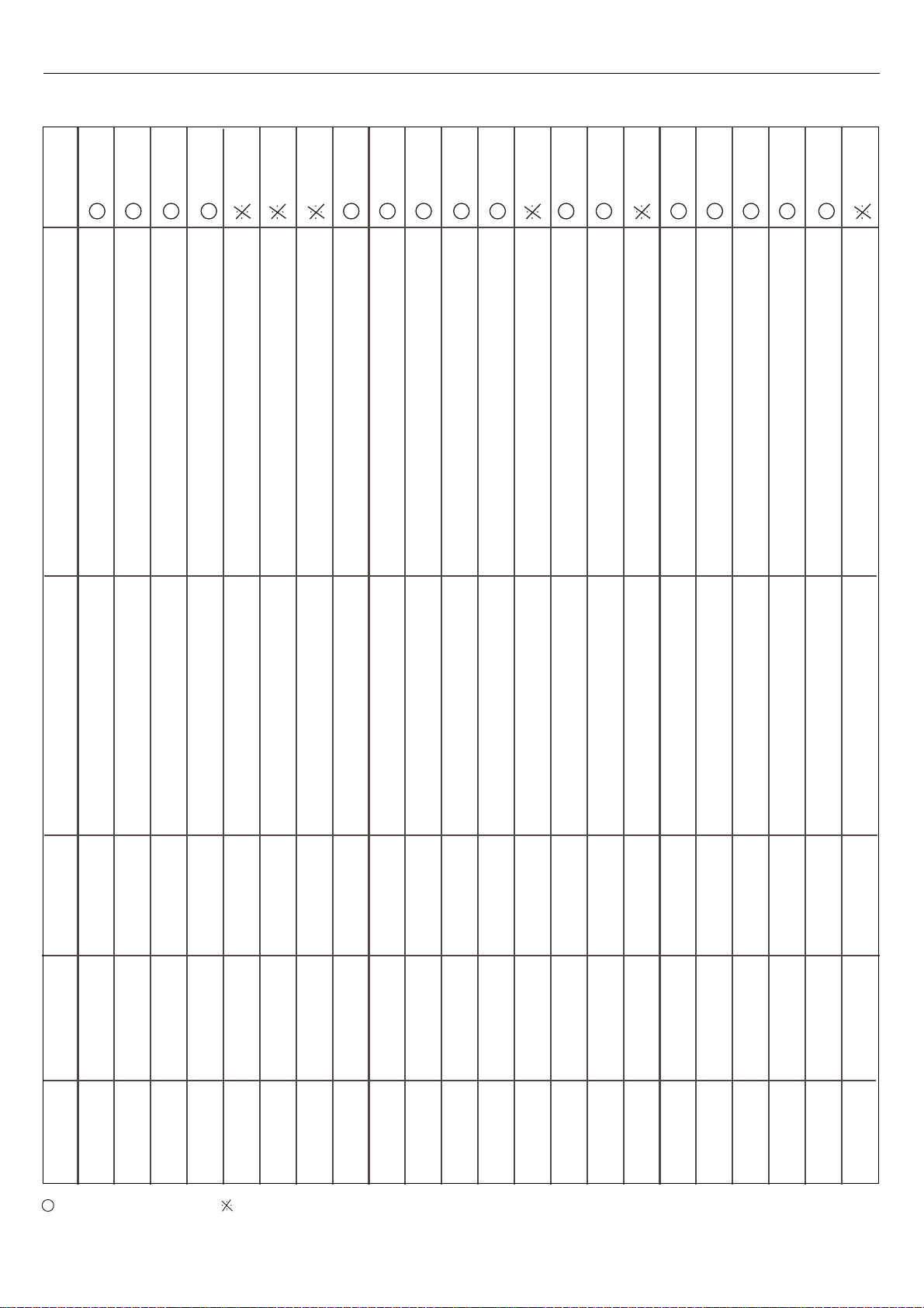
Diagnosis for inverter models
Remarks
Resumable
if lower than
100 degree
Reason
Sensor broken down or short circuit for more than 2m continuously
Sensor broken down or short circuit for more than 2m continuously
Sensor broken down or short circuit for more than 2m continuously
Sensor broken down or short circuit for more than 2m continuously
CT check abnormal 3 times in 30m
Failure description
Indoor ambient temp. sensor failure
Indoor coil temp. sensor failure
Outdoor ambient temp. sensor failure
Outdoor coil temp. sensor failure
Over-current protection
Failure code
for central control
01D
02D
11D
12D
10D
Fault phase, short of phase, out of balance greatly
High pressure switch acts 3 times in 30m
High pressure abnormal
14D
Communication abnormal for more than 4m continuously
Power supply abnormal
Communication between wired controller
and indoor abnormal
22D
06D
Communication abnormal for more than 4m continuously
Float switch broken down for more than 25m continuously
Outside signal broken down for more than 10s
Sensor broken down or short circuit for more than 2m continuously
Solenoid valve act incorrectly 3 times continuously
Sensor broken down or short circuit for more than 2m continuously
EEPROM data missing
Low pressure switch acts in normal running
The discharging temperature is higher than 120degree
Communication between indoor and outdoor abnormal
Drainage system abnormal
Outside alarm signal input
Gas pipe temp. sensor abnormal
Temperature protection malfunction
Discharging temp. sensor abnormal
EEPROM abnormal
Pressure abnormal(low pressure)
Compressor overheat
05D
21D
30D
20D
31D
15D
17D
26D
15D
Indoor operation mode is different with the running indoor unit.
Sensor broken down or short circuit for more than 2m continuously
Sensor broken down or short circuit for more than 2m continuously
Spdu module temperature is too high
Outdoor DC motor abnormal or cooling & heating abnormal
Abnormal mode
Outdoor coil B(suction temp sensor-for MRV II)
Outdoor discharging B(oil temp sensor-for MRV II)
SPDU module temperature protection
Outdoor DC motor failure or system failure
23D
18D
15D
07D
08D
Failure code
on wired controller
01(01H)
02(02H)
74(4AH)
73(49H)
72(48H)
83(53H)
71(47H)
07(07H)
06(06H)
08(08H)
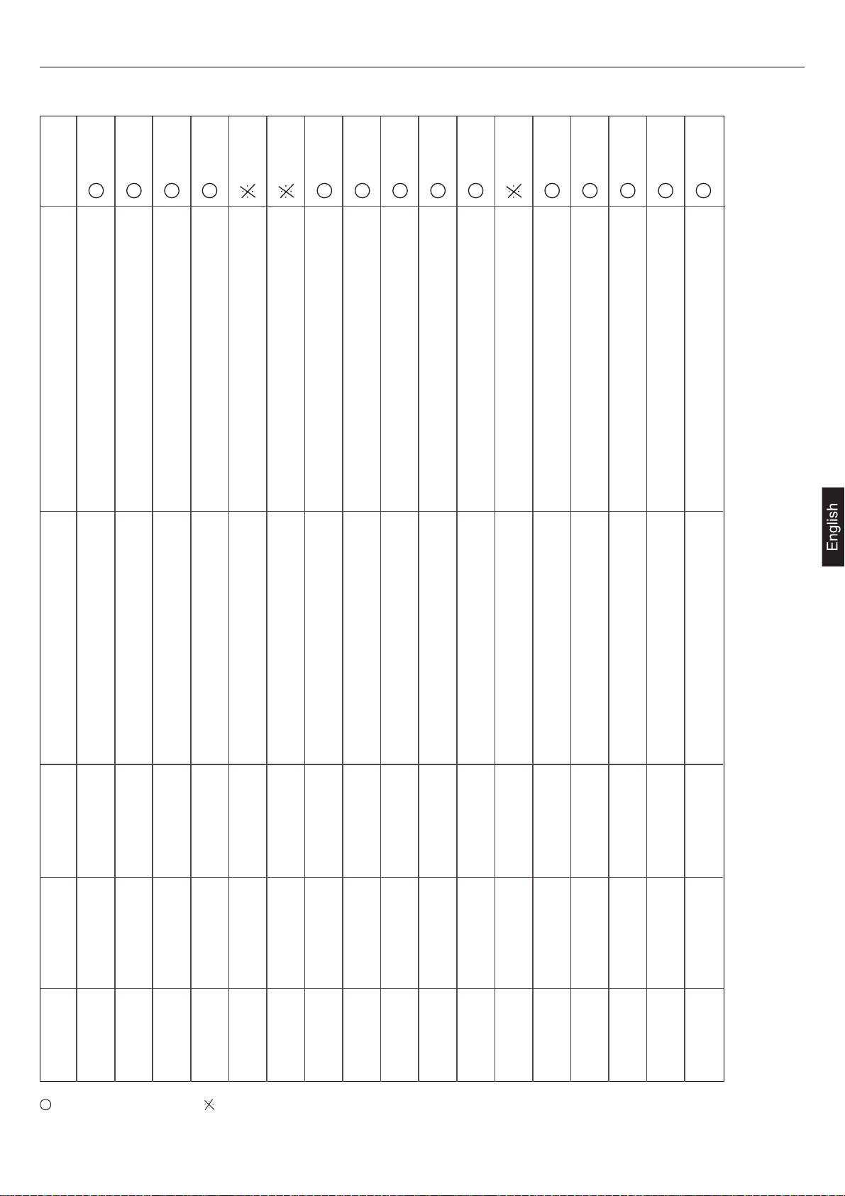
Flash times
for remote type
1
2
3
4
5
6
7
8
9
10
shows resumable fault, shows it is not resumable fault.
16
11(0BH)
11
03(03H)
12
13(0DH)
13
76(4CH)
14
05(05H)
15
84(54H)
16
80(50H)
17
12(0CH)
18
75(4BH)
19
77(4DH)
20
20(32D)
21
36(54D)
22
Page 23
Troubleshooting
Diagnosis for On-Off models
Remarks
Resumable
if lower than
100 degree
Sensor broken down or short circuit for more than 2m
continuously
Sensor broken down or short circuit for more than 2m
continuously
Sensor broken down or short circuit for more than
2m continuously
Sensor broken down or short circuit for more than
2m continuously
CT check abnormal 3 times in 30m / Fault phase,
short of phase,out of balance greatly
Failure description Reason
Indoor ambient temp. sensor failure
Indoor coil temp. sensor failure
Outdoor ambient temp. sensor failure
Outdoor coil temp. sensor failure/ Compressor
discharging temp. sensor abnormal
Over-current protection / Power supply
abnormal
Failure code
for central control
01D
02D
11D
12D
10D
High pressure switch acts 3 times in 30m/Low pressure
switch acts in normal running
Communication abnormal for more than 4m continuously
Communication abnormal for more than 4m continuously
Float switch broken down for more than 25m continuously
Outside signal broken down for more than 10s
Sensor broken down or short circuit for more than 2m
continuously
Solenoid valve act incorrectly 3 times continuously
High/Low pressure abnormal
Communication between wired controller and
indoor abnormal
Communication between indoor and outdoor
abnormal
Drainage system abnormal
Outside alarm signal input
Gas pipe temp. sensor abnormal
Temperature protection malfunction
EEPROM abnormal
14D
06D
05D
21D
30D
20D
31D
17D
EEPROM data missing
The discharging temperature is higher than 120degree
Indoor operation mode is different with the running
indoor unit.
Sensor broken down or short circuit for more than 2m
continuously
Sensor broken down or short circuit for more than 2m
continuously
Compressor overheat
Abnormal mode
Outdoor coil B(suction temp sensor-for MRV II)
Outdoor discharging B(oil temp sensor-for
MRV II)
15D
23D
18D
15D
Failure code
on wired controller
01(01H)
02(02H)
74(4AH)
73(49H)
72(48H)
83(53H)
07(07H)
06(06H)
Flash times
for remote type
1
2
3
4
5
6
8
9
shows resumable fault, shows it is not resumable fault.
08(08H)
10
17
11(0BH)
11
03(03H)
12
13(0DH)
13
05(05H)
15
80(50H)
17
12(0CH)
18
75(4BH)
19
77(4DH)
20
Page 24
Precaution For Installation
Please read these "Safety Precautions" first then accurately execute the installation work.
Though the precautionary points indicated herein are divided under two headings, and , those
points which are related to the strong possibility of an installation done in error resulting in death or serious injury are
listed in the section. However, there is also a possibility of serious consequences in relationship to the
points listed in the section as well. In either case, important safety related information is indicated, so by all
means, properly observe all that is mentioned.
After completing the installation, along with confirming that no abnormalities were seen from the operation tests, please
explain operating methods as well as maintenance methods to the user (customer) of this equipment, based on the owner's
manual. Moreover, ask the customer to keep this sheet together with the owner's manual.
This system should be applied to places as office, restaurant, residence and the like. Application to inferior environment
such as engineering shop could cause equipment malfunction.
Please entrust installation to either the company which sold you the equipment or to a professional contractor. Defects
from improper installations can be the cause of water leakage, electric shocks and fires.
Execute the installation accurately, based on following the installation manual. Again, improper installations can result
in water leakage, electric shocks and fires.
When a large air-conditioning system is installed to a small room, it is necessary to have a prior planned countermeasure
for the rare case of a refrigerant leakage, to prevent the exceeding of threshold concentration. In regards to preparing
this countermeasure, consult with the company from which you perchased the equipment, and make the installation
accordingly. In the rare event that a refrigerant leakage and exceeding of threshold concentration does occur, there is
the danger of a resultant oxygen deficiency accident.
For installation, confirm that the installation site can sufficiently support heavy weight. When strength is insufficient,
injury can result from a falling of the unit.
Execute the prescribed installation construction to prepare for earthquakes and the strong winds of typhoons and
hurricanes, etc. Improper installations can result in accidents due to a violent falling over of the unit.
For electrical work, please see that a licensed electrician executes the work while following the safety standards related
to electrical equipment, and local regulations as well as the installation instructions, and that only exclusive use circuits
are used. Insufficient power source circuit capacity and defective installation execution can be the cause of electric
shocks and fires.
Accurately connect wiring using the proper cable, and insure that the external force of the cable is not conducted to
the terminal connection part, through properly securing it. Improper connection or securing can result in heat generation
or fire.
Take care that wiring does not rise upward, and accurately install the lid/service panel. Its improper installation can
also result in heat generation or fire.
When setting up or moving the location of the air conditioner, do not mix air etc. or anything other than the designated
refrigerant (R410A) within the refrigeration cycle. Rupture and injury caused by abnormal high pressure can result from
such mixing.
Always use accessory parts and authorized parts for installation construction. Using parts not authorized by this company
can result in water leakage, electric shock, fire and refrigerant leakage.
WARNING
CAUTION
WARNING
WARNING
CAUTION
CAUTION
Execute proper grounding. Do not connect the ground wire to a gas pipe, water pipe, lightning rod or a telephone ground
wire. Improper placement of ground wires can result in electric shock.
The installation of an earth leakage breaker is necessary depending on the established location of the unit. Not installing
an earth leakage breaker may result in electric shock.
Do not install the unit where there is a concern about leakage of combustible gas. The rare event of leaked gas collecting
around the unit could result in an outbreak of fire.
For the drain pipe, follow the installation manual to insure that it allows proper drainage and thermally insulate it to
prevent condensation. Inadequate plumbing can result in water leakage and water damage to interior items.
18
Page 25
Is The Unit Installed Correctly
Confirm the following items for safe and comfortable use of air conditioner.
The installation work is to be burden on the sales dealer, and do not conduct it by yourself.
Installation place
Avoid installing the air conditioner near
the place where possibility of inflammable
gas leakage exists.
Explosion (Ignition) may occur.
Select the place so as not to annoy
neighbor with the hot air or noise.
Install the unit at well ventilated place. Install the air conditioner firmly on the
foundation that can fully support the
weight of the unit.
If not, it may cause vibration or noise.If some obstacle exist, it may cause
capacity reduction or noise increase.
Snow protection work is necessary
where outdoor unit is blocked up by snow.
It is advisable not to install the air conditioner at the following special place.
It may cause malfunction, consult the
sales dealer when you have to install
the unit on such a place.
For details consult your sales dealer.
The place where corrosive gas generates
(Hot spring area etc.)
The place where salt breeze blows
(Seaside etc.)
The place where dense soot smoke exists
The place where humidity is extraordinarily high
The place where near the machine which
radiates the electromagnetic wave
The place where voltage variation is considerably large
Electric work
The electric work must be burden on the authorized engineer with qualification for electric work and grounding work, and
the work must be conducted in accordance with electric equipment technical standard.
The power source for the unit is to be of exclusive use.
An earth leakage breaker should be installed.(This is necessary to prevent electric shock.)
The unit must be grounded.
When you change your address or the installation place
Special technology is required for removal or reinstallation of air conditioner, consult the sales dealer. Besides, construction
expense is charged for removal or reinstallation.
For inspection and maintenance
The capacity of air conditioner will decrease by contamination of inside of unit when it is used for about three years although
depending upon the circumstances under which it is used, and so in addition to the usual maintenance service, special
inspection/maintenance service is necessary. It is recommended to make a maintenance contract (charged) by consulting
your sales dealer.
19
Page 26
Installation Procedure
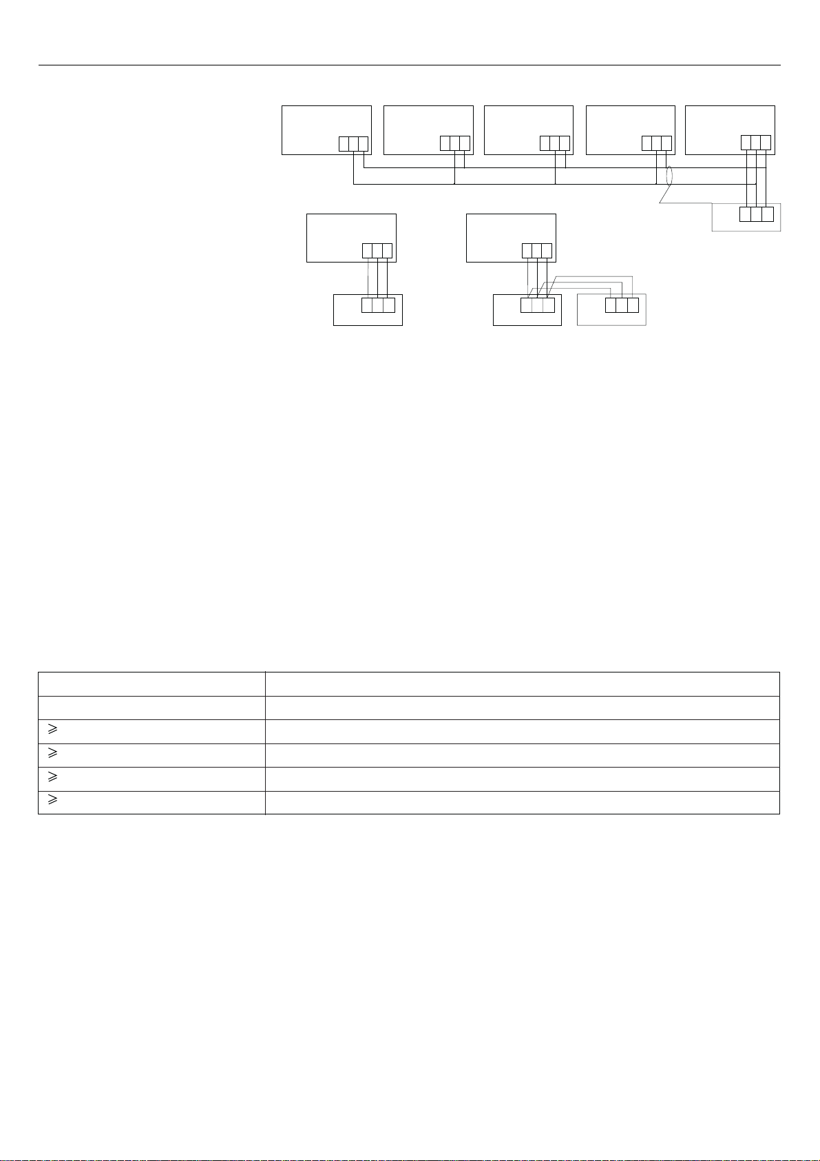
Wiring connections of wired controller
A
Wired controller Wired controller Wired controller Wired controller Wired controller
Wired controller
Indoor 16Indoor 15Indoor NIndoor 2Indoor 1
(master unit)
1 2 3 1 2 3 1 2 3 1 2 3 1 2 3
BC
Indoor 1
Wired controller
Poler wire
Wired controller
1 2 3
A B C
Indoor 1
Wired controller
Poler wire
Wired controller
1 2 3
Poler wire
A B C
Wired controller
Control wiring of wired
controller, polar.
A B C
A B C
Wired controller
There are three methods to connect wired controller and the indoor units:
A.One wired controller can control max. up to 16 sets of indoor units. In this case, 3 pieces of polar wire must connect
the wired controller and the master unit (the indoor unit connected with wired controller directly), the others connect with
the master unit through 2 pieces of polar wire.
B. One wired controller controls one indoor unit. The indoor unit connects with the wired controller through 3 pieces
of polar wire.
C. Two wired controllers control one indoor unit. The wired controller connected with indoor unit is called master one,
the other is called slave one. Master wired controller and indoor unit; master and slave wired controllers are all connected
through 3 pieces of polar wire.
Note:
The method A needs to set the PCB function switch. The method C needs to set the controller function switch.
Communication wiring
The wired controller is equipped with special communication wiring in the accessories. 3-core terminal (1-white 2-yellow
3-red) is connected with the terminal A, B, C of wired controller respectively.
The communication wiring is 4 meter long. If the actual length is more than it, please distribute wiring according to below
table:
Communication wiring length(m) Dimensions of wiring
2
< 100 0.3mm
100 and <200 0.5mm
200 and <300 0.75mm
300 and <400 1.25mm
400 and <600 2mm
x 3-core shielded wire
2
x 3-core shielded wire
2
x 3-core shielded wire
2
x 3-core shielded wire
2
x 3-core shielded wire
*One side of the shielded sheet of communication wire must be earthed.
20
Page 27
Installation Procedure
Indoor Unit
NOTE
All wiring of this installation must comply with NATIONAL, STATE AND LOCAL REGULATIONS. These instructions
do not cover all variations for every kind of installation circumstance. Should further information be desired or should particular
problems occur, the matter should be referred to your local distributor.
WARNING
BE SURE TO READ THESE INSTRUCTIONS CAREFULLY BEFORE BEGINNING INSTALLATION. FAILURE TO FOLLOW
THESE INSTRUCTIONS COULD CAUSE SERIOUS INJURY OR DEATH, EQUIPMENT MALFUNCTION AND/OR
PROPERTY DAMAGE.
Before installation (Before finishing installation, do not throw the attached parts installation needs)
Confirm the way to move the unit to the installation place.
Before moving the unit to the installation place, do not remove their packages. When having to remove the package, use
a soft material or protection board with rope to lift the unit assembly to avoid unit damage or bumping a scrape.
Choose installation place
The chosen installation place should meet the following requirements and get the user's consent.
Place ensures ideal airflow distribution.
The passage of airflow has no obstacles.
When importing outside air, it should be imported directly from outdoors. (If the pipe can not be extended, it also can not
be imported from top)
Place ensures enough space for maintenance.
The pipe length between indoor and outdoor unit is in the permitted limit (referring to outdoor unit installation part).
The indoor unit, outdoor unit, electric wire and connection wire is at least 1m away from television and radio. This is to
avoid the image disturbance and noise caused by the above mentioned home appliance. (Even if 1m away, if the
electromagnetic wave is too strong, it can also cause noise.)
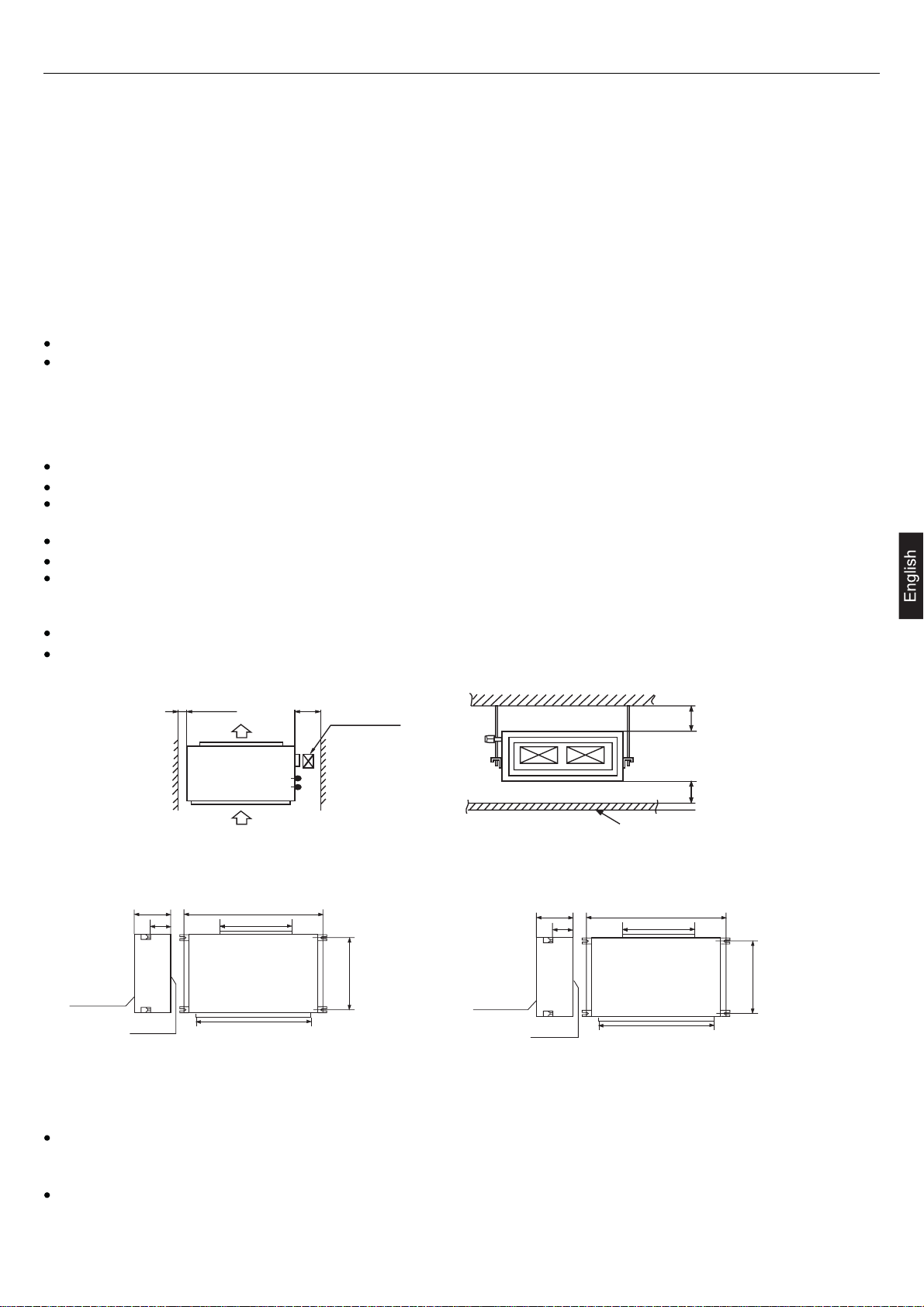
The indoor unit can install on the ceiling, which height is no more than 3m.
Install and use the hoisting screw. Check if the installation place can bear the weight of unit assembly. If not certain,
strengthen it before install the unit.
Over 100 Over 900
Air out
Air in
Checking meatus
(600x600)
Over 300
Over 200
Ceiling
Installation for indoor unit
1.The position relation among hoisting screw (unit: mm)
890
600
750
794
Down side
360
250
Up side
1270
853
794
1103
AD362AHERA
Down side
360
250
Up side
AD282AHEAA - AD362AHEAA
AD482AHEAA - AD482AHERA
AD602AHEAA - AD602AHERA
2.If necessary, cut the opening installation and checking needed on the ceiling. (If having ceiling)
Before installation, finish the preparation work of all the pipes (refrigerant, drainage) and wire (wire controller connection
wire, indoor and outdoor unit connection wire) of indoor unit, so that after installation, they can be immediately connected
with outdoor unit.
Cut the opening on the ceiling. Maybe it needs to strengthen the ceiling to keep the ceiling even and flat and prevent the
ceiling from vibration. For details, please consult to the builder.
21
Page 28
Installation Procedure
Indoor Unit
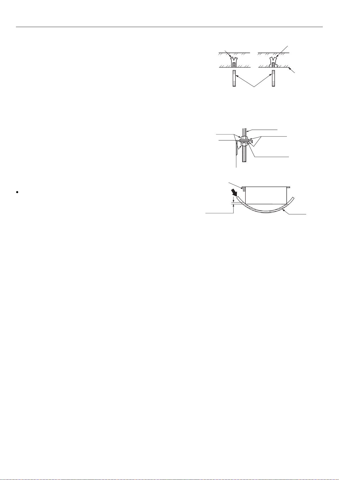
3. Hanger bolts installation
Use care of the piping direction when the unit is installed.(Use
M10 screw bolt)
In order to bear the weight of the unit, for existed ceiling, using
foundation screw bolt, and for new ceiling, using burying embedded
screw bolt, burying screw bolt or spot supplied other parts.
Before going on installation, adjust the gaps with ceiling.
4. Installation of indoor unit
Fix the indoor unit to the hanger bolts.
If required, it is possible to suspend the unit to the beam, etc.
Directly by use of the bolts without using the hanger bolts.
Note
When the dimensions of main unit and ceiling holes does not
match, it can be adjusted with the slot holes of hanging bracket.
5. Adjusting to the levelness
(a) Adjust the out-of levelness using a level or by the following
method.
Make adjustment so that the relation between the lower surface
of the unit proper and water level in the hose becomes as given
below.
(b)Unless the adjustment to the levelness is made properly,
malfunctioning or failure of the float switch may occur.
Hole-in anchor
Hole-in plug
M10 nut
Main unit
Piping side
Supply water
Water level
0~5 mm
(0~0.2")
Bring the piping side slightly lower.
Insert
Concrete
Hanging bolt M10
Hanging bolt
M10 washer
M10 spring washer
PVC hose
22
Page 29
Installation Procedure
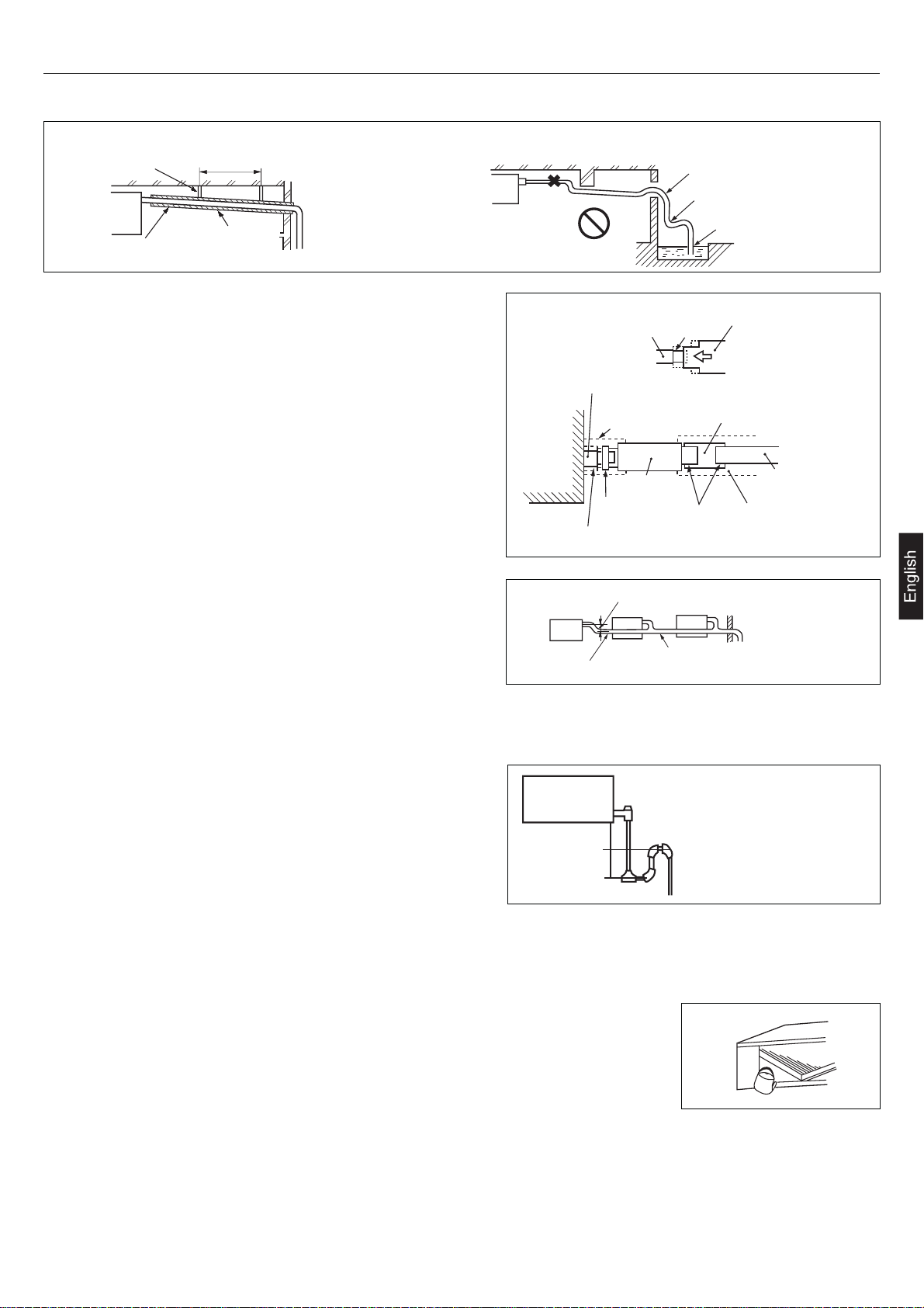
(a)
Drain piping should always be in a downhill grade (1/50~1/100) and avoid riding across an elevation or making traps.
Drain Piping
Good piping
Suspension
bolts
Heat
insulation
(b)
When connecting the drain pipe to unit, pay suffcient attention
1.5m ~ 2m
A downhill grade
of 1/100 or more
not to apply excess force to the piping on the unit side. Also,
fix the piping at a point as close as possible to the unit.
(c)
For drain pipe, use hard PVC general purpose pipe VP-25(I.D.1")
which can be purchased locally. When connecting, insert a
PVC pipe end securely into the drain socket before tightening
securely using the attached drain hose and clamp. Adhesive
must not be used connection of the drain socket and drain
hose (accessory).
(d)
When constructing drain piping for several units, position the
common pipe about 100 mm below the drain outlet of each
unit as shown in the sketch. Use VP-30(11/4") or thicker pipe
for this purpose.
Improper piping
Avoid riding across an elevation
Air vent
Drain socket
Drain socket
Pipe cover(large)
[for insulation]
(accessory)
Main unit
Drain hose
(accessory)
Clamp
(accessory)
Pipe cover(small) [for insulation]
(accessory)
Secure the elevation as high as possible (approx. 100 mm)
Keep free from traps
Do not pipe under water
Stage
difference
part
Adhesion
Drain hose
VP-25 joint
(field purchased)
Pipe cover [for insulation]
(field purchased)
VP-25
(field purchased)
The stiff PVC pipe put indoor side should be heat insulated.
(e)
(f)
Avoid putting the outlet of drain hose in the places with irritant gas generated. Do not insert the drain hose directly into
A downhill grade of 1/100 or more
VP-30
drainage, where the gas with sulfur may be generated.
(g)
Because the drain spout is at the position, which negative
pressure may occur. So with the rise of water level in the drain
pan, water leakage may occur. In order to prevent water leakage,
we designed a backwater bend. The structure of backwater
bend should be able to be cleaned. As the right figure shown,
use T type joint. The backwater bend is set near the air
conditioner.
H1H2
H1=100mm or the static pressure of
air sending motor
H2=1/2H1 (or between 50~100mm)
As figure shown, set a backwater bend in the middle of drain
hose.
Drainage Test
(1)
Conduct a drainage test after completion of the electrical work.
(2)
During the trial, make sure that drain flows properly through the piping and that no
water leaks from connections.
(3)
In case of a new building, conduct the test before it is furnished with the ceiling.
(4)
Be sure to conduct this test even when the unit is installed in the heating season.
Procedures
(a)
Supply about 1000 cc of water to the unit through the air outlet using a feed water pump.
(b)
Check the drain while cooling operation.
23
Page 30
Installation Procedure
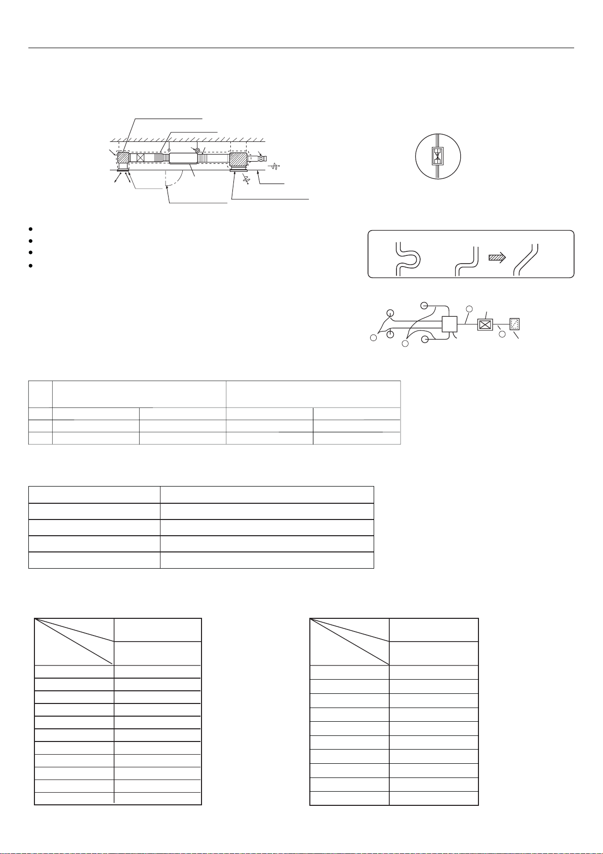
Air Duct
Please consult the after-sales service personnel for the choosing and installation of suction inlet, suction duct, discharging
outlet and discharging duct. Calculating the design drawing and outer static pressure, and choose the discharging duct
with proper length and shape.
muffler cavity (air sending)
Sacking joint
Insulation
Air outlet
A
Air conditioner
main unit
Checking meatus
Air volume adjuster
Ceiling
Air suction grille with air filter
The length difference among every duct is limited below 2:1.
Reduce the length of duct as possible as can.
Reduce the amount of bend as possible as can.
Use heat insulation material to bind and seal the part connecting main
unit and the flare part of air discharging duct. Perform duct installation
work, before the fitment of ceiling.
Calculation method of the dimension of the simple quadrate air duct
Presuming the unit length friction impedance of the duct is
1Pa/m, when the dimension of one side of the air duct is
fixed as 250mm, as shown below:
AD362AHERA - AD482AHEAA - AD482AHERA
AD602AHEAA - AD602AHERA
Air volume
A
2400m
600m3/h(10m3/min)
B
3
/h(40m3/min) 250x560(mmxmm)
Duct
250x190(mmxmm)
AD282AHEAA - AD362AHEAA
3
1200m
/h (20m3/min) 250x310(mmxmm)
3
/h (5m3/min)
300m
DuctAir volume
250x120(mmxmm)
Enlarging chart of profile chart A
Vibration resistance hook
B
A
Static pressure
box
A
Air conditioner
Good exampleBad exampleBad example
A
Equipped with
air filter (bought)
The calculation of duct resistance (the simple calculation is as follow table)
Straight part
Bend part
Air out part
Static pressure box
Air inlet grille (with air filter)
Calculate as per 1m length 1Pa, 1Pa/m
Each bend takes as a 3~4m long straight duct
Calculate as 25Pa
Calculate as 50Pa/each
Calculate as 40Pa/each
The chosen chart of simple duct
Note:1Pa/m=0.1mmAg/m
Shape
Item
Air volume
3
/h(m3/n)
m
100
200
300
400
500
600(10)
800
1,000
1,200(20)
1,400
1,600
Shape
Item
Square duct
Dimension
(mmxmm)
250 x 60
250 x 90
250 x 120
250 x 140
250 x 170
250 x 190
250 x 230
250 x 270
250 x 310
250 x 350
250 x 390
Air volume
m3/h(m3/n)
1,800(30)
2000
2400
3,000(50)
3,500
4,000
4,500
5,000
5,500
6,000(100)
Square duct
Dimension
(mmxmm)
250 x 430
250 x 470
250 x 560
250 x 650
250 x 740
250 x 830
250 x 920
250 x 1000
250 x 1090
250 x 1180
24
Page 31

Installation Procedure
The attentive matters in installation of air suction and discharging duct
Recommend to use anti-frost and sound-absorbing duct. (locally bought)
The duct installation work should be finished before the fitment of ceiling.
The duct must be heat insulated.
The specific air-discharging outlet should be installed at the place where the
airflow can be reasonably distributed.
The surface should leave a checking meatus for checking and maintenance.
The examples of improper installation
Do not use air inlet duct and take the ceiling inner side as duct instead.
The result is because of the irregular outer air mass, strong wind and
sunshine, the humidity is increased.
There may be water drop on the outside of duct. For cement and other
new constructions, even if not taking ceiling inner side as duct, the
humidity will also be so high. At this time, use glass fiber to perform
heat preservation to the whole. (use iron net to bind the glass fiber)
Maybe exceeding the unit operation limit (for example: when indoor
dry bulb temperature is 35 C, wet bulb temperature 24 C), it may lead
to overload of compressor.
Affected by the capacity of air discharging fan, the strong wind in the
outer duct and wind direction, when unit air sending volume exceeds
the limit, the discharged water of heat exchanger will overflow, leading
to water leakage.
Special air discharging outlet
Use screw bolt to fix
Air
Air
Improper example
Air discharging fan
Air Duct
Duct
25
Page 32

Installation Procedure
Refrigerant Pipe
The gas side pipe, liquid side pipe must be faithfully heat insulated, if no heat insulation, it may cause water leakage.
The outdoor unit has been charged with refrigerant.
When connect the pipe to the unit or dismantling the pipe from the unit, please follow the figure shown, use spanner and
torque spanner together.
When connect cone nut, the inner side and outside of cone nut should paste with refrigerant oil. Use hand to twist 3-4
rings, then fasten with spanner.
Referring to Table I to confirm the fasten torque. Too tight may damage nut leading to leakage.
Check if the connection pipe leaks, then do heat insulation treatment, as below figure shown.
Only use seal cushion to bind the joint part of air pipe and heat insulation parts.
Paste the refrigerant oil here
Torque spanner
Spanner
Pipe joint
Cone nut
Drain hose connection mouth
VP25 PVC pipe
Middle size seal cushion (accessory)
(Use seal cushion to
bind the pipe joint)
Clamp
Heat insulation (accessory)
(for liquid pipe)
Heat insulation (accessory)
(for gas pipe)
Gas pipe
Liquid pipe
80 510
Liquid pipe
Air inlet Air outlet
Gas pipe
530
Table I
Specification
of pipe
9.52mm
15.88mm
19.05mm
Electric box
Upper
Down side
Tighten torque
3270~3990 N.cm
(333~407 kgf.cm)
6180~7540 N.cm
(630~770 kgf.cm)
9720~11860 N.cm
(990~1210 kgf.cm)
310
30
Cone
dimension
A (mm)
12.0~12.4
18.6~19.0
22.9~23.3
Cone
45 2
A
90 0.5
R0.4~0.8
26
Page 33

Installation Procedure
WARNING
DANGER OF BODILY INJURY OR DEATH
TURN OFF ELECTRIC POWER AT CIRCUIT BREAKER OR POWER SOURCE BEFORE MAKING ANY ELECTRIC
CONNECTIONS.
GROUND CONNECTIONS MUST BE COMPLETED BEFORE MAKING LINE VOLTAGE CONNECTIONS.
Precautions for Electrical wiring
Electrical wiring work should be conducted only by authorized personnel.
Do not connect more than three wires to the terminal block. Always use round type crimped terminal lugs with insulated
grip on the ends of the wires.
Use copper conductor only.
Selection of size of power supply and interconnecting wires
Select wire sizes and circuit protection from table below. (This table shows 20 m length wires with less than 2% voltage drop.)
Electrical Wiring
Item
Phase
Model
AD282AHEAA
AD362AHEAA
AD362AHERA
AD482AHEAA
AD482AHERA
AD602AHEAA
AD602AHERA
AD282AHEAA
AD282AHEAA
AD362AHEAA
AD362AHERA
Wiring connection
Make wiring to supply power to the outdoor unit, so that the power for the indoor unit is supplied by terminals.
AD282AHEAA
AD362AHEAA
AD362AHERA
Indoor unit
terminal block
3 30 2.5 3020 30
3 30 4.0 3020 30
Switch breaker
123
Circuit breaker
(A)
Overcurrent protector
rated capacity (A)
AD282AHEAA
AD362AHEAA
AD362AHERA
AD482AHEAA
AD482AHERA
Y/G
AD602AHEAA
AD602AHERA
Power source
wire size
(minimum)
2
(mm
)
Indoor unit
terminal block
Earth leakage breaker
Switch
breaker(A)
123
Leak
current(mA)
301 40 30 6.0 40
Y/G
Outdoor unit
terminal block
Power supply :1PH, 220-230V~, 50Hz
123LN
Y/G
Outdoor unit
terminal block
27
Y/G
RS TN 123
Y/G
Power supply:380-400V, 3N~, 50Hz
Page 34

Page 35

IST HA084 Rev. 00-2007
• Si prega di leggere il presente manuale di istruzioni prima di utilizzare il climatizzatore
• Conservare il presente manuale per ogni futura evenienza.
CLIMATIZZATORE UNITARY SMART
CANALIZZATO 100Pa
MANUALE DI ISTRUZIONI
MANUALE DI INSTALLAZIONE
On-Off
AD282AHEAA
AD362AHEAA
AD482AHEAA
AD602AHEAA
Inverter
AD362AHERA
AD482AHERA
AD602AHERA
Page 36

Indice
Precauzioni per l'uso 3
Denominazione dei componenti 5
Tasti e display del comando a filo 6
Funzionamento 8
Manutenzione 13
Guida alla ricerca dei guasti 14
Diagnostica 15
Precauzioni per l'installazione 17
Installazione del comando a filo 19
Installazione dell'unità interna 20
2
Page 37

• Si prega di leggere il presente manuale di istruzioni prima di
utilizzare il climatizzatore.
• Le precauzioni di sicurezza di seguito elencate si
suddividono in PERICOLO e ATTENZIONE. La voce
PERICOLO riguarda precauzioni che, se non seguite,
possono portare a serie conseguenze, quali morte, gravi
lesioni, ecc. Tuttavia, anche la voce ATTENZIONE riguarda
precauzioni che, se non osservate, possono causare seri
problemi, a seconda della situazione.
• Tenere le Precauzioni di sicurezza sempre a portata di
mano, affinché possano essere consultate in qualsiasi
momento.
PERICOLO
Non dirigere il flusso d'aria fredda
direttamente sulle persone, e non lasciar
diminuire troppo la temperatura
ambiente, perché ciò può causare
problemi di salute.
Non inserire oggetti nella griglia di
aspirazione o nella bocca di uscita
dell'unità esterna mentre il climatizzatore
è in funzione. Il ventilatore che gira ad alta
velocità può causare gravi ferite.
In caso di disfunzioni quali odore di bruciato, arrestare
immediatamente l'apparecchio e staccare l'alimentazione.
Contattare il servizio assistenza. Se in questi casi il
climatizzatore continuasse a funzionare, potrebbe subire gravi
danni, oppure potrebbe scoppiare un incendio.
ATTENZIONE
Non utilizzare l'apparecchio allo scopo di
conservare cibo, opere d'arte,
attrezzature di precisione, per
allevamento di animali o coltivazione di
piante.
Non agire sull'interruttore con le mani
bagnate.
Non installare l'apparecchio vicino a un
caminetto o altre apparecchiature per il
riscaldamento.
Non versare acqua sul climatizzatore per pulirlo.
Non disporre piante o animali
direttamente esposti al flusso dell'aria.
Usare un fusibile con le specifiche
elettriche appropriate. Non usare
assolutamente filo di rame o di acciaio al
posto del fusibile.
Non appoggiare alcun oggetto
sull'apparecchio e non salirvi sopra.
Non collocare bombolette di gas
infiammabile e non utilizzare liquidi spray
nelle vicinanze dell'apparecchio.
Non avviare il climatizzatore se la griglia di
uscita dell'unità esterna è stata rimossa.
Non arrestare o avviare l'apparecchio
agendo sull'interruttore dell'alimentazione.
Non toccare la zona di uscita del flusso
d'aria mentre il deflettore è in movimento.
Non collocare bollitori e simili nei pressi
dell'unità interna e del telecomando: la
condensa che si può accumulare a
causa del vapore generato può
provocare un corto circuito.
Aerare la stanza di tanto in tanto se è
contemporaneamente in funzione un
elettrodomestico a gas. Un'aerazione
insufficiente può causare soffocamento.
Controllare periodicamente che il
supporto dell'unità esterna sia in perfette
condizioni.
Prima di pulire l'apparecchio, spegnere il climatizzatore e
staccare l'alimentazione.
Non appoggiare vasi di fiori o contenitori d'acqua
sull'apparecchio.
Contattare il Servizio assistenza per eventuali riparazioni.
Operazioni non adeguate potrebbero provocare folgorazioni,
incendi e perdite d'acqua.
Contattare il Servizio assistenza in caso di trasloco. Operazioni
non adeguate potrebbero provocare folgorazioni, incendi e
perdite d'acqua.
Precauzioni per l’uso
3
Page 38

Specifiche di smaltimento
Il climatizzatore è contrassegnato con questo
simbolo, ciò significa che i prodotti elettrici ed
elettronici non possono essere smaltiti insieme ai rifiuti domestici non differenziati.
Non cercare di demolire il sistema da soli: la
demolizione del sistema di condizionamento, nonchè il recupero
del refrigerante, dell’olio e di qualsiasi altra parte devono essere
eseguiti da un installatore qualificato in conformità alla legislazione
locale e nazionale vigente in materia.
I climatizzatori devono essere trattati presso una struttura specializzata nel riutilizzo, riciclaggio e recupero dei materiali. Il corretto
smaltimento del prodotto eviterà le possibili conseguenze negative all’ambiente e alla saluta dell’uomo. Per maggiori informazioni
contattare l’installatore o le autorità locali.
Le batterie devono essere tolte dal telecomando e smaltite separatamente conformemente alla legislazione locale e nazionale
vigente in materia.
Norme di sicurezza
Prima di utilizzare il climatizzatore, leggere attentamente il presente Manuale di istruzioni. Il produttore declina ogni responsabilità
per eventuali danni derivanti dalla non osservanza delle seguenti
norme di sicurezza.
• Non mettere in funzione un climatizzatore danneggiato. In caso
di dubbio, contattare il rivenditore.
• L'utilizzo del climatizzatore deve avvenire in stretta osservanza
delle istruzioni contenute nel presente Manuale.
• L'installazione deve essere eseguita da personale qualificato e
autorizzato. Non tentare di installare l'apparecchio da soli.
• Per ragioni di sicurezza, il climatizzatore deve essere dotato di
messa a terra.
• Prima di aprire il pannello frontale, staccare sempre il cavo dell'alimentazione. Non tirare il cavo, ma estrarre la spina dalla presa di corrente.
• Per eventuali riparazioni, contattare il Servizio Assistenza. Le
riparazioni di carattere elettrico devono essere eseguite da elettricisti qualificati. Operazioni non adeguate possono provocare
gravi danni all'utente.
•
Non danneggiare i componenti del climatizzatore che contengono liquido refrigerante: non perforare, schiacciare o deformare le
tubazioni, e non raschiarne il rivestimento di superficie. Se il refrigerante viene a contatto con gli occhi, può causare gravi lesioni.
• Non ostruire o coprire la griglia di uscita del climatizzatore. Non
inserire dita o altri oggetti nelle griglie di uscita/entrata o nei
deflettori.
• Non lasciar giocare i bambini con il climatizzatore. Non salire
sopra l'unità esterna.
Avvertenze
Limiti di funzionamento
Gamma utile delle temperature ambiente:
BS: Temperatura a
Bulbo Secco
BU: Temperatura a
Bulbo Umido
• Se il cavo dell'alimentazione è danneggiato, deve essere sostituito da personale del servizio assistenza o comunque da personale
qualificato.
• Se il fusibile sulla scheda elettronica salta, sostituirlo con uno di tipo T.3.15A/250VAC.
• Il metodo di cablaggio deve essere in linea con lo standard locale.
• Il cavo di alimentazione e il cavo di collegamento non sono forniti.
• Installare un sezionatore di corrente; la distanza tra i due contatti deve essere almeno di 3mm.
• L'altezza minima di installazione dell'unità interna è di 2,5 metri.
• Tutti cavi devono avere il certificato di autenticità Europea
• I cavi di collegamento e di alimentazione non sono forniti
• Se durante l’installazione si rompe un cavo, assicurarsi che il cavo messa a terra non sia interrotto.
• Per ottenere le migliori prestazioni si consiglia di impostare la velocità del ventilatore in funzione dei valori riportati in tabella:.
Temperatura interna
Temperatura esterna
Temperatura interna
Temperatura esterna
Raffreddamento
Riscaldamento
max. BS/BU
min. BS/BU
max. BS/BU
min. BS/BU
max. BS
min. BS
max. BS/BU
min. BS
32/23°C
18/14°C
43/26°C
10/6°C
27°C
15°C
24/18°C
-7°C
32/23°C
18/14°C
43/26°C
-5°C
27°C
15°C
24/18°C
-7°C
InverterON-OFF
4
Page 39

• Per ottenere le migliori prestazioni si consiglia di impostare la velocità del ventilatore in funzione dei valori riportati in tabella:.
Specifiche del cavo di collegamento:
H05RN-F 4G 0.75mm
2
Denominazione dei componenti
Temperatura ambiente Modalità operativa Velocità ventilatore consigliata
> 40°C Raffredddamento bassa
< 20°C Raffreddamento alta
< -5°C Riscaldamento bassa
> 18°C Riscaldamento alta
5
Unità interna
Condotto
Entrata aria
Uscita aria
Condotto
Tubo scarico condensa
Page 40

1. Tasto CLOCK (Orologio)
Per impostare l'orologio.
2. Tasto TIMER
Per selezionare TIMER ON (accensione), TIMER OFF (spegnimento), TIMER ON/OFF (accensione/spegnimento).
3. Tasto CHECK
Per effettuare l'auto-diagnosi.
4. Tasti + e - (Più e meno)
Per predisporre l’orario ed il timer.
5. Tasto FILTER
Per la pulizia del filtro.
6. Tasto ON/OFF
Per l’avvio e l’arresto dell’apparecchio.
7. Tasto MODE (Modalità operativa)
Per selezionare la modalità AUTO, COOL (raffreddamento),
DRY (deumidificazione), HEAT (riscaldamento) e FAN (ventilazione).
8. Tasto FAN (Ventilatore)
Per selezionare la velocità del ventilatore: bassa (LOW), media
(MED), alta (HIGH).
9. Tasto SWING
Per modificare la direzione del flusso d'aria.
10. Tasto HEALTH (Salute)
Per impostare la funzione Health.
11. Tasti TEMP + e - (Temperatura)
Per impostare la temperatura desiderata.
12. Tasto RECOVERY
Per impostare la modalità "cambio d'aria".
13. Tasto RESET
Per ripristinare le impostazioni iniziali.
Note:
• Le informazioni di cui sopra illustrano quanto visualizzato
dal display, quindi differiscono da quelle visualizzate nel
corso del funzionamento vero e proprio.
• Per questi modelli le funzioni 5, 9, 10 non sono dispo-
nibili.
Tasti e display del comando a filo YR-E12
6
DEFROST
1 7
2
3
HEALTH
C
F
4
5
6
SET RECOVER Y
CHECK
8
9
10
11
12
13
Page 41

[MODE]
[AUTO]: modalità operativa Auto
[FAN ONLY]: modalità operativa Ventilazione
[COOL]: modalità operativa Raffreddamento
[DRY]: modalità operativa Deumidificazione
[HEAT]: modalità operativa Riscaldamento
[HEAT] [TES]: in modalità Riscaldamento, è disponibile un
sistema ausiliario di riscaldamento elettrico
[FAN]
[AUTO]: ventilazione con velocità auto
[HIGH]: ventilazione con velocità alta
[MED]: ventilazione con velocità media
[LOW]: ventilazione con velocità bassa
[FIX]: ventilazione con velocità fissa
[CENTRAL]: controllo centralizzato
[OPERATION]: funzionamento
[STAND BY]: attesa
[PRE-HEAT]: pre-riscaldamento
[DEFROST]: auto-sbrinamento
[FILTER]: richiesta di pulizia del filtro
[HEALTH]: funzione Health (salute)
[CEN.ADD]: impostazione numerica centralizzata delle unità, il
numero viene visualizzato al posto della temperatura
[SYS.ADD]: impostazione numerica del sistema, il numero
viene visualizzato al posto della temperatura
[CHECK]: auto-diagnosi
[DEMAND]: funzionamento forzato; quando è attivo la scritta
[CENTRAL] lampeggia
[SWING] [MANUAL]: regolazione della direzione del flusso
d'aria
[ROOM TEMP.]: visualizzazione temperatura ambiente
[SET TEMP.]: visualizzazione temperatura impostata
[TIMER]
[ON]: modalità Timer On
[OFF]: modalità Timer Off
[ON] [OFF]: modalità Timer On-Off
[ON] [OFF] [DAILY]: Timer On e Timer Off si alternano duran-
te il giorno
[CLOCK]: visualizzazione ora dell'orologio
[UP] [DOWN]: indicatori della discesa e risalita del filtro
[VENTILATION]
[AUTO]: modalità Ventilazione automatica
[RECOVERY]: modalità Ventilazione "cambio d'aria"
[NORMAL]: modalità Ventilazione normale
Tasti e display del comando a filo
7
DEFROST
Page 42

Funzionamento in Ventilazione
(1) Avvio del climatizzatore:
premere il tasto ON/OFF, il sistema si avvia e il display del
comando a filo si accende.
(2) Selezione della modalità operativa:
premere il tasto MODE, ad ogni pressione del tasto il display del comando nella sezione [MODE] varia come segue:
[FAN ONLY] [COOL] [DRY] [HEAT] [AUTO]
[FAN ONLY]
Selezionare [FAN ONLY].
(3) Selezione della velocità del flusso d'aria:
premere il tasto FAN, ad ogni pressione del tasto il display
del comando nella sezione [FAN] varia come segue:
[HIGH] [MED] [LOW] [HIGH]
Selezionare la velocità desiderata.
(4) Arresto del climatizzatore:
premere il tasto ON/OFF, il climatizzatore si spegne, sul display del comando restano visualizzati solo l'ora e la temperatura ambiente.
8
Modalità Ventilation
(disponibile solo per i modelli con funzione "Aria pulita" e "Cambio d'aria")
Premere il tasto RECOVERY, l'unità entrerà in modalità Ventilation (ventilazione); ad ogni pressione del tasto, la modalità Ventilazione
varia come segue:
[ ] [VENTILATION] [AUTO] [VENTILATION] [RECOVERY] [VENTILATION] [NORMAL] [ ]
Selezionare la modalità Ventilazione desiderata.
2
3
1, 4
Page 43

Funzionamento AUTO,
Raffreddamento, Deumidificazione e Riscaldamento
(1) Avvio del climatizzatore:
premere il tasto ON/OFF, il sistema si avvia e il display del
comando a filo si accende.
(2) Selezione della modalità operativa:
premere il tasto MODE, ad ogni pressione del tasto il display del comando nella sezione [MODE] varia come segue:
[FAN ONLY] [COOL] [DRY] [HEAT] [AUTO]
[FAN ONLY]
Selezionare la modalità operativa desiderata.
(3) Impostazione della temperatura:
premere i tasti TEMP "+" o "-", ad ogni pressione la temperatura impostata aumenta o diminuisce di 1°C; sul display
del comando appare [SET].
(4) Selezione della velocità del flusso d'aria:
premere il tasto FAN, ad ogni pressione del tasto il display
del comando nella sezione [FAN] varia come segue:
[AUTO] [HIGH] [MED] [LOW] [AUTO]
Selezionare la velocità desiderata.
(5) Regolazione direzione del flusso d'aria:
premere una volta il tasto SWING per attivare la funzione
Swing, sul display del comando appare [SWING]. Premendo il tasto SWING una seconda volta, la funzione viene disattivata e la scritta [SWING] scompare dal display.
(6) Attivazione funzione Health (salute):
premere una volta il tasto HEALTH, sul display del comando appare [HEALTH]. Premendo il tasto HEALTH una
seconda volta, la funzione Health viene disattivata e la scritta [HEALTH] scompare dal display. Questa funzione è disponibile solo per i modelli dotati di ionizzatore.
(7) Arresto del climatizzatore:
premere il tasto ON/OFF, il climatizzatore si spegne, sul display del comando restano visualizzati solo l'ora e la temperatura ambiente.
9
2
4
5
HEALTH
3
C
SET RECOVER Y
CHECK
6
1, 7
Page 44

Modalità Timer
Regolare correttamente l’orologio prima di utilizzare la modalità Timer. Premere il tasto
CLOCK, sul display del comando la scritta [CLOCK] lampeggia. Per regolare l'ora esatta, premere i tasti "+" e "-". Quindi premere il tasto SET per confermare.
Modalità TIMER ON
Premere il tasto TIMER, ad ogni pressione del tasto il display del comando nella sezione
[TIMER] varia come segue:
[ON] [OFF] [ON] [OFF] [ON] [OFF] [DAILY] [ ]
Selezionare [TIMER] [ON], sul display del comando la scritta [TIMER] [ON] lampeggia.
Premere i tasti "+" e "-" per impostare l'orario di Timer On e quindi premere il tasto SET per
confermare.
Modalità TIMER OFF
Premere il tasto TIMER, ad ogni pressione del tasto il display del comando nella sezione
[TIMER] varia come segue:
[ON] [OFF] [ON] [OFF] [ON] [OFF] [DAILY] [ ]
Selezionare [TIMER] [OFF], sul display del comando la scritta [TIMER] [OFF] lampeggia.
Premere i tasti "+" e "-" per impostare l'orario di Timer Off e quindi premere il tasto SET per
confermare.
Modalità TIMER ON-OFF
Premere il tasto TIMER, ad ogni pressione del tasto il display del comando nella sezione
[TIMER] varia come segue:
[ON] [OFF] [ON] [OFF] [ON] [OFF] [DAILY] [ ]
Selezionare [TIMER] [ON] [OFF], sul display del comando la scritta [TIMER] [ON] lampeggia.
Premere i tasti "+" e "-" per impostare l'orario di Timer On e quindi premere il tasto SET per
confermare. [TIMER] [ON] rimane acceso e [TIMER] [OFF] lampeggia.
Premere i tasti "+" e "-" per impostare l'orario di Timer Off e quindi premere il tasto SET per
confermare.
La sequenza dell'orario per Timer On e Timer Off determinerà la modalità [TIMER] [ON] [OFF]
oppure [TIMER] [OFF] [ON].
Note:
1. Se i due orari sono identici, l'unità assumerà la modalità Timer Off oppure Timer On a
seconda dello stato di funzionamento al momento dell'impostazione del timer. Se l'unità è
in funzione, quando arriva l'orario impostato l'unità assumerà la modalità Timer Off. Al contrario, se l'unità è spenta, quando arriva l'orario impostato l'unità assumerà la modalità
Timer On.
2. Durante l'impostazione della modalità Timer, se non viene premuto alcun tasto per 10
secondi consecutivi, per l'unità è come se venisse premuto il tasto SET.
Disattivazione della modalità Timer
• In modalità Timer, premere il tasto TIMER: l'unità abbandona la modalità Timer in uso; i dati
impostati vengono memorizzati e l'unità entra nella modalità Timer seguente.
• Dopo l'impostazione del timer, premere il tasto ON/OFF per disattivare la modalità Timer.
Quando l'unità entrerà di nuovo in funzione, la modalità Timer sarà continua (cioè disattivata).
10
Page 45

11
Funzionamento
Funzione Auto-diagnosi
Sia con il climatizzatore spento che acceso, premere il tasto CHECK per attivare la funzione Auto-diagnosi per tutte le unità interne di
ogni gruppo. Sul display del comando a filo appariranno le scritte [CHECK] e [UNIT NO.]: verranno visualizzati in sequenza i numeri
delle unità interne (il numero dell'unità è espresso in decimali). Contemporaneamente, nella sezione di visualizzazione dell'orario, verranno visualizzate l'eventuale anomalia presente e l'ultima anomalia in ordine di tempo. Il formato di visualizzazione è [XX:YY]: XX indica
il tipo di anomalia presente (se non vi è alcuna anomalia, verrà visualizzato "--"); YY indica l'ultima anomalia in ordine di tempo.
Il codice di errore per ciascuna unità interna viene visualizzato per 3 secondi. Dopo che sono stati visualizzati i codici di errore per tutte
le unità interne dell'intero gruppo, la funzione Auto-diagnosi si disattiverà automaticamente.
Cancellazione del codice di errore
• Premere il tasto CHECK per 5 secondi: il comando a filo invierà il segnale di "cancellazione del codice di errore" attuale, ma la storia
delle anomalie passate verrà conservata.
• Premere il tasto CHECK per 15 secondi: la storia delle anomalie passate verrà cancellata dal comando a filo, mentre viene mantenuta la visualizzazione dell'anomalia attuale.
Page 46

Modalità Riscaldamento
Funzione “HOT KEEP”
La funzione “HOT KEEP” viene attivata nei seguenti casi:
• Quando viene avviata la modalità Riscaldamento:
Per evitare che l’unità emetta aria fredda, quando viene avviata la modalità Riscaldamento il ventilatore dell’unità interna si ferma se
la temperatura ambiente è bassa. Attendere per circa 2 o 3 minuti, dopodiché il ventilatore riprenderà a funzionare normalmente in
modalità Riscaldamento.
• Durante la funzione di auto-sbrinamento:
Quando c’è la possibilità che l’apparecchio si congeli, la modalità Riscaldamento si arresta automaticamente per 5-10 minuti ogni
ora circa e viene attivata la funzione di auto-sbrinamento.
Una volta completato l’auto-sbrinamento, la modalità Riscaldamento viene riattivata automaticamente.
• Quando entra in funzione il sensore temperatura ambiente:
Quando la temperatura ambiente si alza, il sensore fa rallentare la velocità del ventilatore fino a LO (bassa) o lo fa arrestare del tutto
se lo scambiatore di calore dell’unità interna ha una temperatura bassa. Non appena la temperatura ambiente si abbassa di nuovo,
il ventilatore riprenderà a funzionare normalmente in modalità Riscaldamento.
Funzionamento dei modelli pompa di calore
• Il funzionamento dei modelli pompa di calore si basa su un meccanismo che, per mezzo del gas refrigerante, concentra il calore
dell’aria esterna per riscaldare l’ambiente interno.
• Funzione di “auto-sbrinamento”
Quando si utilizza un modello a pompa di calore per riscaldare una stanza, sullo scambiatore di calore dell’unità etserna si
accumula della brina man mano che la temperatura esterna scende. Poiché la brina accumulata riduce le prestazioni in
riscaldamento, il climatizzatore deve necessariamente entrare in modalità “auto-sbrinamento”.
Durante il funzionamento in auto-sbrinamento, il funzionamento in modalità Riscaldamento viene interrotto.
• Temperatura esterna e potenza in Riscaldamento
Per un climatizzatore a pompa di calore, la potenza in Riscaldamento diminuisce con il diminuire
della temperatura esterna.
• Periodo di pre-riscaldamento
Poiché il funzionamento di un modello a pompa di calore utilizza la circolazione di un flusso
d’aria calda per riscaldare l’intero volume di una stanza, occorre del tempo prima che la
temperatura ambiente si alzi. Si consiglia di accendere il climatizzatore con un po’ di anticipo
nelle mattine molto fredde.
12
Page 47

Manutenzione
Portare l’interruttore dell’alimentazione
generale in posizione OFF.
PUNTI DA OSSERVARE
Non toccare l’apparecchio con le mani
bagnate.
Non usare acqua calda o liquidi volatili.
ATTENZIONE
• Non aprire la griglia di entrata dell’aria finché il ventilatore non è completamente fermo.
• Una volta spento l’apparecchio, il ventilatore continua a girare per un certo tempo per forza di inerzia.
Pulizia del filtro
1. Pulire il filtro dell’aria sbattendolo leggermente o utilizzando un aspirapolvere. È più
efficace pulire il filtro con acqua. Se il filtro è molto sporco, sciogliere del detergente
neutro in acqua tiepida (circa 30°C), e immergervi il filtro, quindi risciacquare il filtro con
acqua pulita.
2. Dopo aver asciugato bene il filtro, reinserirlo nel climatizzatore.
ATTENZIONE
• Non asciugare il filtro sul fuoco.
• Non far funzionare il climatizzatore senza il filtro.
Manutenzione e pulizia dell’apparecchio
• Pulire con un panno morbido e asciutto.
• Se l’apparecchio è molto sporco, sciogliere del detergente neutro in acqua tiepida e immergervi il panno. Dopo aver passato il
panno, rimuovere il detersivo con acqua pulita.
Manutenzione a fine stagione
• Lasciare in funzione il climatizzatore in modalità Ventilazione in una giornata di bel tempo allo scopo di asciugare le parti interne
dell’unità.
• Staccare l’alimentazione elettrica. Infatti, si ha un consumo di energia elettrica anche quando il climatizzatore non è in funzione.
• Pulire il filtro e reinserirlo nel climatizzatore.
Manutenzione a inizio stagione
• Controllare che non vi siano ostacoli davanti alle griglie di aspirazione e di uscita delle unità interna ed esterna.
• Accertarsi che il filtro dell’aria sia pulito.
• Inserire l’alimentazione elettrica almeno 12 ore prima di avviare il climatizzatore.
13
Page 48

Guida alla ricerca dei guasti
Si sente rumore di acqua che scorre.
Si sentono scricchiolii.
Emissione di odori.
Durante il funzionamento, viene emessa della
nebbiolina dall’unità interna.
L’apparecchio passa in modalità Ventilazione
durante il Raffreddamento.
Il climatizzatore non si riavvia dopo l’arresto.
In modalità Deumidificazione, non c’è diffusione
d’aria oppure la velocità di ventilazione non può
essere modificata.
L’unità esterna produce acqua o vapore in
modalità Riscaldamento.
In modalità Riscaldamento, il ventilatore dell'unità interna continua a funzionare anche dopo l'arresto del climatizzatore.
All’avviamento del climatizzatore, quando il compressore si avvia o si arresta durante il funzionamento o quando il climatizzatore viene spento, si avvertono talvolta dei
rumori di acqua che scorre. Si tratta del flusso del refrigerante all’interno delle tubazioni e non costituisce un’anomalia.
Ciò è causato dalla dilatazione o contrazione della plastica dovuta alle variazioni di
temperatura.
Cattivi odori vengono emessi dall’unità interna. Questi odori sono dovuti al fumo di
sigaretta o alla vernice dei mobili presenti nella stanza, che vengono assorbiti dall’apparecchio e rimessi in circolo.
In modalità Raffreddamento o Deumidificazione, una nebbiolina bianca viene talvolta emessa dalla griglia d’uscita dell'unità interna. Ciò è dovuto alla condensa formatasi per la brusca variazione di temperatura nell'aria.
Per evitare che si accumuli brina sullo scambiatore di calore dell’unità interna, talvolta avviene automaticamente il passaggio in modalità Ventilazione, ma l’apparecchio torna presto in modalità Raffreddamento.
Anche se viene premuto il tasto di funzionamento, il raffreddamento, la deumidificazione o il riscaldamento non sono attivabili per tre minuti dopo l’arresto del climatizzatore. Ciò è dovuto all’attivazione del circuito di protezione. Attendere tre minuti.
Se la temperatura ambiente è eccessivamente fredda in modalità deumidificazione,
il ventilatore riduce automaticamente la velocità di ventilazione a intervalli regolari.
Questo si verifica quando la brina accumulata sull’unità esterna viene eliminata
(durante l’operazione di auto-sbrinamento).
Per eliminare il calore in eccesso, il ventilatore dell'unità interna continua a girare per
un certo tempo dopo l'arresto del climatizzatore.
I seguenti fenomeni non costituiscono anomalie di funzionamento:
14
Page 49

Diagnostica mod. Inverter
Tabella dei codici di errore
I codici di errore contrassegnati con (*) possono essere resettati togliendo l’alimentazione per 2 minuti.
Se al riavvio il codice di errore persiste, contattare il centro assistenza autorizzato.
Unità con comando
a filo: codice di errore
01(01H)
02(02H)
74(4AH)
73(49H)
72(48H)
83(53H)
71(47H)
07(07H)
06(06H)
08(08H)
11(0BH)
03(03H)
13(0DH)
76(4CH)
05(05H)
84(54H)
80(50H)
12(0CH)
75(4BH)
77(4DH)
20(32D)
36(54D)
Unità con comando centrale:
codice errore
01D
02D
11D
12D
10D
14D
22D
06D
05D
21D
30D
20D
31D
15D
17D
26D
15D
23D
18D
15D
07D
08D
Descrizione dell’anomalia
Sonda temp. ambiente unità interna
difettosa
Sonda temp. tubazioni unità interna
difettosa
Sonda temp. ambiente unità esterna
difettosa
Sonda temp. tubazioni unità esterna
difettosa
Protezione sovracorrente
Pressione tubazioni troppo alta
Anomalia alimentazione
Errore di comunicazione tra comando a filo
e unità interna
Errore di comunicazione tra unità interna
ed esterna
Anomalia del sistema di drenaggio
condensa
Mancanza di segnale dall’unità esterna
verso l’unità interna
Sonda temp. tubazioni gas difettosa
Anomalia protezione temperatura
Sonda temp. mandata compressore
difettosa
EEPROM difettosa
Pressione troppo bassa
Compressore surriscaldato
Funzionamento anomalo della modalità
operativa
Sonda temp. aspirazione diffettosa
Sonda temp. olio difettosa
Protezione modulo temp. SPDU
Motore DC UE guasto o guasto del
sistema
Causa
Sensore guasto o corto circuito per più di 2 min.
consecutivi
Sensore guasto o corto circuito per più di 2 min.
consecutivi
Sensore guasto o corto circuito per più di 2 min.
consecutivi
Sensore guasto o corto circuito per più di 2 min.
consecutivi
CT (controllo amperometrico) anormale 3 volte in 30 min
Interruttore alta pressione aperto 3 volte in 30 min
Fase invertite, mancanza fase, tensione insufficiente
Comunicazione anormale per più di 4 min. consecutivi
Comunicazione anormale per più di 4 min. consecutivi
Galleggiante non funzionante per più di 25 min.
continuativi
Segnale assente per più di 10 sec.
Sensore guasto o corto circuito per più di 2 min.
consecutivi
Valvola solenoide malfunzionante per 3 volte
consecutive
Sensore guasto o corto circuito per più di 2 min.
consecutivi
Mancanza dati EEPROM unità interna
Interruttore bassa pressione aperto durante il normale
funzionamento
Temperatura di mandata superiore a 120°
Funzionamento diverso dalla modalità impostata
Sensore guasto o corto circuito per più di 2 min.
consecutivi
Sensore guasto o corto circuito per più di 2 min.
consecutivi
Temp. modulo SPDU troppo alta
Anomalia motore DC UE o raffreddamento e
riscaldamento anormali
Note
*
*
*
*
*
*
*
*
*
*
*
** se la temp è
inferiore a 100°**
*
*
15
Page 50

Diagnostica mod. ON-OFF
Tabella dei codici di errore
I codici di errore contrassegnati con (*) possono essere resettati togliendo l’alimentazione per 2 minuti.
Se al riavvio il codice di errore persiste, contattare il centro assistenza autorizzato.
Unità con comando
a filo: codice di errore
01(01H)
02(02H)
74(4AH)
73(49H)
72(48H)
83(53H)
07(07H)
06(06H)
08(08H)
11(0BH)
03(03H)
13(0DH)
05(05H)
80(50H)
12(0CH)
75(4BH)
77(4DH)
Unità con comando
centrale: codice errore
01D
02D
11D
12D
10D
14D
06D
05D
21D
30D
20D
31D
17D
15D
23D
18D
15D
Descrizione dell’anomalia
Sonda temp. ambiente unità interna difettosa
Sonda temp. tubazioni unità interna difettosa
Sonda temp. ambiente unità esterna difettosa
Sonda temp. tubazioni unità esterna difettosa /
Sonda temp. mandata compressore difettosa
Protezione sovracorrente / Anomalia
alimentazione
Pressione troppo bassa/alta
Errore di comunicazione tra comando a filo e
unità interna
Errore di comunicazione tra unità interna ed
esterna
Anomalia del sistema di drenaggio condensa
Mancanza di segnale dall’unità esterna verso
l’unità interna
Sonda temp. tubazioni gas difettosa
Anomalia protezione temp.
EEPROM difettosa
Compressore surriscaldato
Funzionamento anomalo della modalità
operativa
Sonda temp. aspirazione difettosa
Sonda temp. olio difettosa
Causa
Sensore guasto o corto circuito per più di 2 min. consecutivi
Sensore guasto o corto circuito per più di 2 min. consecutivi
Sensore guasto o corto circuito per più di 2 min. consecutivi
Sensore guasto o corto circuito per più di 2 min. consecutivi
CT (controllo amperometrico) anormale 3 volte in 30 min /
Fase invertite, mancanza fase, tensione insufficiente
Interruttore alta pressione aperto 3 volte in 30 min / interrut-
tore bassa pressione attivo durante il normale funzionamento
Comunicazione anormale per più di 4 min. consecutivi
Comunicazione anormale per più di 4 min. consecutivi
Galleggiante non funzionante per più di 25 min. continuativi
Segnale assente per più di 10 sec.
Sensore guasto o corto circuito per più di 2 min. consecutivi
Valvola solenoide malfunzionante per 3 volte consecutive
Mancanza dati EEPROM unità interna
Temperatura di mandata superiore a 120°
Funzionamento diverso dalla modalità impostata
Sensore guasto o corto circuito per più di 2 min. consecutivi
Sensore guasto o corto circuito per più di 2 min. consecutivi
Nota
*
*
*
*
*
*
*
*
*
*
** se la temp è
inferiore a 100°**
*
16
Page 51

Precauzioni per l’installazione
• Si prega di leggere le presenti “Precauzioni di Sicurezza”
prima di procedere all’attenta esecuzione del lavoro di
installazione.
• Le precauzioni descritte qui di seguito sono divise in:
ATTENZIONE e AVVERTENZE. Le precauzioni sotto la voce
“ATTENZIONE” indicano che un comportamento improprio
potrebbe avere serie conseguenze come morte, lesioni gravi
ecc. Tuttavia, anche le precauzioni riportate sotto la voce
“AVVERTENZE” si riferiscono a situazioni che potrebbero
comportare conseguenze molto serie. Accertarsi di
osservare attentamente queste precauzioni di sicurezza dato
che costituiscono informazioni molto importanti per garantire
la sicurezza.
• Dopo aver completato l’installazione, oltre a confermare che
nessuna anomalia è stata riscontrata nel test di
funzionamento, si prega di spiegare la metodica di
funzionamento e di manutenzione all’utente (cliente) di
questo apparecchio, basandosi sul manuale di istruzioni.
Chiedere inoltre al cliente di conservare questo foglio
unitamente al manuale di istruzioni.
ATTENZIONE
• Questo apparecchio dovrebbe essere installato in luoghi
quali uffici, ristoranti, abitazioni. L’installazione in ambienti più
piccoli quali officine potrebbe causare disfunzioni
dell’apparecchio.
• Si prega di affidare l’installazione alla ditta che ha venduto
l’apparecchio o ad un professionista. Difetti dovuti ad
installazione impropria potrebbero causare perdite d’acqua,
scosse elettriche ed incendi.
• Eseguire l’installazione accuratamente, seguendo le
indicazioni del manuale di installazione. Anche in questo
caso, un’installazione impropria potrebbe provocare perdite
d’acqua, scosse elettriche ed incendi.
• Se un condizionatore di grandi dimensioni viene installato in
una stanza di piccole dimensioni, è necessario predisporre
misure preventive nella rara eventualità di fughe di
refrigerante, per evitare il superamento della soglia di
concentrazione. Riguardo alla predisposizione di queste
misure preventive, consultare la ditta che ha fornito
l’apparecchio, ed installare il climatizzatore secondo quanto
prescritto. Nel raro caso che si verifichi una fuga di
refrigerante e si superi la soglia di concentrazione, vi è
pericolo di incidenti dovuti alla mancanza di ossigeno.
• Verificare che il luogo di installazione possa sostenere
agevolmente il peso dell’apparecchio. Se il supporto è
insufficiente, una caduta dell’apparecchio potrebbe causare
gravi ferite.
• Rispettare le istruzioni di installazione prescritte
nell’eventualità di condizioni atmosferiche avverse.
Un’installazione impropria può provocare incidenti dovuti alla
caduta violenta dell’apparecchio.
• Per i collegamenti elettrici, si prega di fare in modo che un
elettricista autorizzato esegua l’impianto, seguendo le norme
di sicurezza relative alle apparecchiature elettriche, le norme
locali e le istruzioni di installazione, e che siano usati circuiti
dedicati. Una capacità insufficiente del circuito ed
un’installazione difettosa possono essere causa di scosse
elettriche ed incendi.
• Collegare accuratamente i fili utilizzando un cavo adeguato,
ed accertarsi che la forza esterna del cavo non scarichi sulla
morsettiera, fissandolo adeguatamente. Un collegamento o
fissaggio improprio potrebbe provocare riscaldamento od
incendi.
• Controllare che i fili non siano rivolti verso l’alto ed installare
accuratamente il pannello di servizio. Anche l’installazione
impropria di quest’ultimo potrebbe provocare riscaldamento
od incendi.
• Quando si installa o si sposta il condizionatore, non far
entrare aria o altro, oltre al refrigerante prescritto (R410A),
all’interno del circuito di refrigerazione. Questo potrebbe
provocare rotture e ferite dovute alla pressione
anormalmente alta.
• Utilizzare sempre accessori e pezzi autorizzati per
l’installazione. L’utilizzo di pezzi non autorizzati dal produttore
potrebbe provocare perdite d’acqua, scosse elettriche,
incendi e perdite di liquido refrigerante.
AVVERTENZE
• Eseguire un’adeguata messa a terra. Non collegare il filo
della massa a tubi del gas, tubi dell’acqua, aste di
parafulmini o fili di massa del telefono. Una posizione
impropria dei fili di massa può provocare scosse elettriche.
• L’installazione di un sezionatore di corrente è necessaria a
seconda della posizione dell’apparecchio. La mancata
installazione di un sezionatore di corrente può provocare
scosse elettriche.
• Non installare l’apparecchio dove vi siano possibilità di fughe
di gas combustibili. La rara eventualità che un gas si
raccolga intorno all’apparecchio potrebbe provocare un
incendio.
• Per quanto riguarda il tubo di scarico condensa, seguire il
manuale di installazione per assicurare che lo scarico
avvenga in modo appropriato, ed isolarlo termicamente per
prevenire la formazione di condensa. Un’opera idraulica non
appropriata può provocare perdite d’acqua e danni alla
mobilia per infiltrazioni d’acqua.
• Vi ricordiamo che l’installazione degli impianti deve essere
effettuata a regola d’arte al fine di permettere l’accessibilità
diretta degli apparecchi per la loro manutenzione. Rimane
escluso dalla copertura della garanzia l’eventuale utilizzo di
ponteggi, gru, ecc. ai fini della manutenzione.
17
Page 52

Per un’installazione corretta
Accertarsi che siano rispettate le seguenti condizioni per un uso sicuro ed efficace del climatizzatore.
L’opera di installazione è a carico del rivenditore, non installare il climatizzatore da soli.
Collegamenti elettrici
I collegamenti elettrici devono essere effettuati da personale qualificato e autorizzato e il lavoro deve essere eseguito in accordo con
le norme in vigore.
• L’alimentazione del climatizzatore deve essere di uso esclusivo del climatizzatore.
• Dovrebbe essere installato un sezionatore di corrente per evitare scosse elettriche.
• Deve essere effettuata la messa a terra.
In caso di trasloco o di riposizionamento del climatizzatore
In caso di trasloco o di riposizionamento del climatizzatore, rivolgersi a personale specializzato.
Controllo e manutenzione
Le prestazioni del climatizzatore tendono a diminuire dopo un utilizzo di circa 3 anni (a seconda delle condizioni di utilizzo). È quindi
necessario, oltre alla manutenzione ordinaria, effettuare anche dei controlli straordinari per mezzo di una ditta specializzata.
Non installare il climatizzatore nelle
vicinanze di un luogo dove esista la
possibilità di fughe di gas infiammabile.
Potrebbero verificarsi esplosioni o
incendi.
Non installare l’unità esterna in un luogo
dove l’aria calda o il rumore possano
dare fastidio ai vicini.
LUOGO DI INSTALLAZIONE
Installare l’apparecchio in un luogo ben
ventilato. Se l’apparecchio è circondato
da ostacoli, si possono verificare
diminuzioni nelle prestazioni o aumento
del livello di rumorosità.
È necessario predisporre una protezione
dalla neve per l’unità esterna nei luoghi
soggetti a nevicate. Per maggiori
dettagli, consultare il rivenditore.
Installare l’unità esterna su un supporto
che sia in grado di sostenere
saldamente il peso dell’unità. In caso
contrario, si possono verificare vibrazioni
o rumore.
È consigliabile non installare il
climatizzatore nei seguenti luoghi, per
evitare guasti o inconvenienti:
• Luogo dove si generano gas corrosivi
(sorgenti termali, ecc.).
• Luogo dove soffia una brezza
salmastra (paesi di mare, ecc.).
• Luogo dove c’è una densa fuliggine.
• Luogo dove l’umidità relativa è molto
elevata.
• Luogo dove operano apparecchi che
emettono onde elettromagnetiche.
• Luogo soggetto a grossi sbalzi di
tensione.
18
Page 53

Installazione del comando a filo
Collegamento elettrico
del comando a filo
Vi sono tre possibili metodi per il collegamento elettrico tra comando a filo e unità interna:
A. Un unico comando a filo controlla fino a 16 unità interne. In questo caso, 3 fili di segnale collegano il comando a filo all'unità
principale (cioè l'unità interna collegata direttamente al comando a filo) e le altre unità interne sono collegate all'unità principale
tramite 2 fili di segnale.
B. Un comando a filo controlla una unità interna: l'unità interna è collegata al comando a filo per mezzo di 3 fili di segnale.
C. Due comandi a filo controllano una unità interna. Il comando a filo collegato direttamente con l'unità interna è quello principale,
mentre l'altro è il comando secondario. Il comando principale e l'unità interna, e i due comandi principale e secondario sono
collegati per mezzo di 3 fili di segnale.
Nota: il metodo A necessita del settaggio degli switch della scheda elettronica. Il metodo C necessita del settaggio degli switch del
comando a filo.
Cavo di comunicazione del comando a filo
Il comando a filo è dotato di uno speciale cavo di comunicazione fornito insieme al climatizzatore. Il cavo a tre fili (1-bianco, 2-giallo, 3rosso) viene collegato rispettivamente ai morsetti A, B, C del comando a filo.
Il cavo di comunicazione è lungo 4 metri. Se la lunghezza reale è superiore, si prega di distribuire il cavo nel seguente modo:
• Un lato del rivestimento schermato del cavo di comunicazione deve essere dotato di messa a terra.
Lunghezza cavo di comunicazione (m) Sezione del cavo
<100 0,3mm2x cavo schermato a 3 fili
≥100 e <200 0,5mm2x cavo schermato a 3 fili
≥200 e <300 0,75mm2x cavo schermato a 3 fili
≥300 e <400 1,25mm2x cavo schermato a 3 fili
≥400 e <600 2mm
2
x cavo schermato a 3 fili
19
A
comando a filo comando a filo comando a filo comando a filo comando a filo
1 2 3
BC
U.Interna 1
comando a filo
filo di segnale
1 2 3 1 2 3
1 2 3
A B C
comando a filo
U.Interna 1
comando a filo
filo di segnale
comando a filo
1 2 3
1 2 3
A B C
U.Interna 16U.Interna 15U.Interna NU.Interna 2U.Interna 1
unità principale
filo di segnale
A B C
comando a filo
1 2 3
A B C
comando a filo
Page 54

ATTENZIONE
ASSICURARSI DI AVER LETTO ATTENTAMENTE LE PRESENTI ISTRUZIONI PRIMA DI INIZIARE L’INSTALLAZIONE. L’INOSSERVANZA DELLE PRESENTI ISTRUZIONI POTREBBE PROVOCARE FERITE GRAVI O MORTE, DISFUNZIONI DELL’APPARECCHIO
E/O DANNI ALLE COSE.
Predisposizione per l'installazione
• Prima di trasferire l'unità sul luogo di installazione, non rimuovere l'imballo.
• Al momento di rimuovere l'imballo, usare un materiale soffice o una tavola di protezione munita di corde per sollevare l'unità senza
danneggiarla.
Scelta del luogo di installazione
a) Posizione in cui l’aria emessa dal climatizzatore possa circolare liberamente nella stanza.
b) Posizione libera da ostacoli onde evitare di ostruire l’aspirazione e l’uscita dell'aria dall’unità interna.
c) Posizione che preveda gli spazi necessari per la manutenzione.
d) L'aria in entrata deve provenire direttamente dall'esterno.
e) La lunghezza delle tubazioni tra unità interna e unità esterna deve rientrare nei limiti consentiti (vedi il Manuale di installazione dell'u-
nità esterna).
f) Non installare l’apparecchio a meno di 1 metro da televisioni, radio o attrezzature che generano onde elettromagnetiche: ciò
potrebbe causare disturbi delle immagini e rumori.
g) Il soffitto di installazione non deve superare i 3m di altezza.
h) Prima di fissare i bulloni di ancoraggio, verificare che il luogo di installazione possa reggere il peso dell'unità. Se necessario, rinforza-
re il luogo di installazione.
i) Posizione dove l’altezza del soffitto e la distanza dalle pareti sia secondo quanto sotto indicato:
1. Dimensioni del foro sul soffitto e posizione dei bulloni di ancoraggio
2. Rinforzare il soffitto se necessario
• Prima di installare l'unità interna, completare i collegamenti delle tubazioni (refrigerante, scarico condensa) e i collegamenti elettrici,
cosicché, una volta installata l'unità interna, questa può essere immediatamente collegata all'unità esterna.
• Effettuare l'apertura sul soffitto. Se necessario, rinforzare e livellare il soffitto per evitare che si producano vibrazioni.
Installazione dell'unità interna
(600x600)
Più di 100
Più di 900
Uscita aria
Entrata aria
Spazio per la
manutenzione
Soffitto
Più di 300
Più di 200
360
890
250
794
600
750
Lato inferiore
Lato superiore
Lato superiore
360
1270
250
794
853
1103
Lato inferiore
AD282AHEAA - AD362AHEAA
20
AD362AHERA
AD482AHEAA - AD482AHERA
AD602AHEAA - AD602AHERA
Page 55

3. Fissare i bulloni di ancoraggio
Durante l'installazione dell'apparecchio, fare attenzione alla direzione
delle tubazioni.
4. Installare l'unità interna
Fissare l'unità interna ai bulloni di ancoraggio. Se necessario, è
possibile fissare direttamente l'unità a una trave, ecc., utilizzando
delle viti, senza bisogno di bulloni di ancoraggio.
5. Posizionare l'unità a livello
a) Utilizzare una livella o procedere secondo il metodo seguente: il
rapporto tra il lato inferiore dell’unità e il livello dell’acqua nel tubo
scarico condensa deve essere pari al valore indicato in figura.
b) Se l’apparecchio non è installato perfettamente a livello, è possibile
che l’interruttore a galleggiante funzioni male o non funzioni affatto.
Fissaggio interno
Cemento
Bulloni di
ancoraggio M10
Inserire
Bullone di ancoraggio
Dado M10
Unità interna
Rondella M10
Rondella a vite M10
21
Lato tubazioni
Versare acqua
Livello acqua
0~5 mm
(0~0.2")
Inclinare leggermente l'unità dal lato tubazioni
Tubo in PVC
Page 56

(a) Le tubazioni di scarico condensa dovrebbero sempre essere installate con una pendenza verso il basso di 1/50 - 1/100. Evitare di
farle passare attraverso un punto più elevato e di provocare sifoni.
(b) Quando si collegano le tubazioni di scarico condensa all’appa-
recchio, prestare attenzione a non applicare una forza eccessiva
alle tubazioni a lato dell’unità interna. Inoltre, fissare le tubazioni il
più vicino possibile all’apparecchio.
(c) Per le tubazioni di scarico condensa, utilizzare un tubo in PVC
rigido di uso generico VP-25 (I.D.1”). Per il collegamento, inseri-
re l’estremità del tubo di PVC all’interno del raccordo scarico
condensa, quindi stringere bene utilizzando il fermaglio e il tubo
rigido compresi fra gli accessori. Non utilizzare nastro adesivo
per unire il tubo rigido (accessorio) al foro scarico condensa.
(d) Se si deve provvedere alle tubazioni di scarico condensa per
più di una unità interna, posizionare il tubo in comune circa
100mm al di sotto dell’apertura di scarico condensa di ogni uni-
tà (vedi figura). A questo scopo, utilizzare un tubo di tipo VP-30
(11/4”) o altro tubo ancora più spesso.
(e) Isolare termicamente i tubi in PVC posti all’interno dell’edificio. Non predisporre mai uno sfiato.
(g) Evitare di posizionare l’uscita della tubazione di scarico dove possano prodursi odori sgradevoli. Non far sfociare la tubazione di
scarico in un canale di fognatura dove si potrebbe generare gas solforico.
Test di drenaggio
1) Eseguire un test di drenaggio dopo aver completato i collegamenti elettrici.
2) Durante il test, verificare che la condensa scorra regolarmente nelle tuba-
zioni e che non ci siano perdite d’acqua dai giunti.
3) Nel caso di edifici di nuova costruzione, eseguire il test prima che venga
completato il soffitto.
4) Eseguire il test anche se l’apparecchio viene installato durante la stagione
invernale.
Come procedere:
(a) Versare circa 1000cc di acqua dentro l’unità interna attraverso il foro di scarico condensa
utilizzando una pompa per l’acqua.
(b) Verificare lo scarico della condensa in modalità Raffreddamento.
Tubazioni scarico condensa
Non immergere il tubo nell'acqua
Libero da sifoni
Non passare su un'elevazione
Sfiato
Drenaggio condensa corretto Drenaggio condensa errato
1.5m ~ 2m
Bulloni di
ancoraggio
Isolamento
termico
Inclinazione di
1/100 o più
Raccordo scarico
condensa
Raccordo scarico
condensa
Tubo rigido
scarico condensa
Unità interna
Giunto VP-25 (non fornito)
Materiale isolante
grande (accessorio)
Tubo VP-25
(non fornito)
Materiale isolante
(non fornito)
Tubo rigido
(accessorio)
Materiale isolante
piccolo (accessorio)
Fermaglio
Adesivo
Tubo VP-30
Posizione più alta possibile (circa 100mm)
Pendenza verso il basso
pari a 1/100 o più
H1H2
H1= 100mm (o la pressione
statica del motore ventilatore)
H2= 1/2 H1 (o tra 50 e 100mm)
22
Page 57

Si prega di consultare il servizio assistenza post-vendita per la scelta e l'installazione dei condotti di entrata e uscita aria.
Calcolare il tiraggio dell’aria e la pressione statica esterna, e quindi scegliere la lunghezza e la forma dei condotti di uscita dell’aria.
• Limitare la differenza di lunghezza tra le flangie uscita aria a
meno di 2:1.
• Ridurre il più possibile la lunghezza del condotto.
• Ridurre il più possibile il numero di curve. (La curvatura
dovrebbe essere il più ampia possibile).
• Utilizzare materiale termoisolante per unire e sigillare l’unità interna alla flangia uscita aria.
• Eseguire l’installazione dei condotti prima che il soffitto sia finito.
Come calcolare le dimensioni del condotto aria quadrato
Nell'ipotesi che il valore unitario della resistenza del condotto
dovuta all'attrito sia pari a 1Pa/m, calcolare la dimensione del
condotto secondo la seguente tabella, tenendo fissa la
dimensione di uno dei lati a 250mm.
Come calcolare la resistenza del condotto
Dimensioni condotti dell'aria quadrati
Porzione lineare Calcolare 1Pa/m
Porzione con curve Ogni curva corrisponde a 3-4m di condotto lineare
Uscita aria Calcolare 25Pa
Scatola pressione statica Calcolare 50Pa ciascuna
Griglia ripresa aria (con filtro dell'aria) Calcolare 40Pa ciascuna
Volume aria
m3/h (m3/min)
100
200
300
400
500
600 (10)
800
1000
1200 (20)
1400
1600
Dimensioni condotto quadrato
(mm x mm)
250 x 60
250 x 90
250 x 120
250 x 140
250 x 170
250 x 190
250 x 230
250 x 270
250 x 310
250 x 350
250 x 390
Volume aria
m3/h (m3/min)
1800 (30)
2000
2400
3000 (50)
3500
4000
4500
5000
5500
6000 (100)
Dimensioni condotto quadrato
(mm x mm)
250 x 430
250 x 470
250 x 560
250 x 650
250 x 740
250 x 830
250 x 920
250 x 1000
250 x 1090
250 x 1180
Installazione dei condotti di uscita dell'aria
A
Isolamento
termico
Cavità silenziatore
Giunto a sacco
Regolatore volume aria
Uscita
aria
Ingrandimento del gancio
anti-vibrazione
Spazio per la
manutenzione
Unità principale
Soffitto
Griglia ripresa aria con filtro dell'aria
Scatola pressione
statica
Climatizzatore
Dotato di filtro dell'aria
(non fornito)
B
A
A
A
CorrettoErratoErrato
A
B
Volume aria
2400m3/h (40m3/min)
600m3/h (10m3/min)
Dimensioni condotto
250 x 560 (mm x mm)
250 x 190 (mm x mm)
Volume aria
AD482AHEAA - AD482AHERA
Dimensioni condotto
250 x 310 (mm x mm)
250 x 120 (mm x mm)
1200m3/h (20m3/min)
300m3/h (5m3/min)
23
AD282AHEAA
AD362AHERA
AD362AHEAA
-
AD602AHEAA - AD602AHERA
-
Page 58

Avvertenze per l’installazione dei condotti dell’aria
• Si raccomanda l'uso di condotti anti-gelo e fonoassorbenti.
• L'installazione dei condotti dell'aria deve essere completata prima della costruzione del soffitto.
• Il condotto dell'aria deve essere isolato termicamente.
• L'uscita dell'aria deve essere posizionata in un luogo dove l'aria possa distribuirsi uniformemente
nella stanza.
• Lasciare uno spazio utile per l'ispezione e la manutenzione.
Esempi di installazione errata
• Per l'aspirazione dell'aria non viene utilizzato un condotto ma il lato
interno del soffitto. Il risultato è un'elevata umidità, data dalla massa
irregolare dell'aria esterna, dal vento forte e dalla luce solare.
• Formazione di condensa sull'esterno del condotto dell'aria. In edifici
di cemento e altri tipi di costruzioni nuove, l'umidità è elevata. In
questo caso, usare fibra di vetro per isolare termicamente il tutto.
• Se vengono superati i limiti di funzionamento (per es., temperatura
interna bulbo secco 35°C, bulbo umido 24°C), può verificarsi un
sovraccarico del compressore.
• A seconda della potenza del ventilatore, dell'aria nel condotto
esterno e della direzione dell'aria, se il volume unitario dell'aria
supera il limite consentito, l'acqua di scarico dello scambiatore di
calore trabocca e si verificano perdite d'acqua.
Aria
Aria
Condotto
Usare un bullone
a vite per fissare
Uscita aria speciale
Ventilatore aria in uscita
Esempio di installazione errata
24
Page 59

•
L'unità esterna è caricata con gas refrigerante dalla casa produttrice.
•
Fare riferimento alla Fig. 1 nel collegare o rimuovere le tubazioni dall’unità. Usare insieme chiave e chiave torcente.
•
Applicare dell’olio refrigerante sul raccordo e sulla flangia, sia all’interno che all’esterno.
•
Tenere i tubi centro contro centro, quindi avvitare il dado a mano per 3-4 giri.
•
Stringere la flangia con la chiave (per il momento torcente, fare riferimento alla Tabella 1). Se stretti troppo, i dadi possono
danneggiarsi e quindi causare perdite di gas.
•
Verificare che non vi siano fughe di gas nelle zone collegate con flangia. Quindi, isolare termicamente sia i tubi del gas che quelli del
liquido come indicato in Fig. 2. Senza isolamento termico, può formarsi della condensa.
•
Ricoprire i giunti dei tubi e il foglio isolante con una fascia avvolgente.
Tubazioni refrigerante
Fascia avvolgente (per ricoprire il giunto)
R0.4 ~ 0.8
A
90
0.5
45
2
Applicare olio refrigerante
Fig 1 Fig 2
Chiave torcente
Chiave
Giunto del tubo
Flangia
Fermaglio
Tubo gas
Tubo liquido
Foglio isolante
Foglio isolante
Diametro
tubazioni
Momento
torcente
A(mm)
Dimensioni flangia
9.52mm
3270~3990N.cm
(333~407kgf.cm)
9720~11860N.cm
12.0~12.4
6180~7540N.cm
(630~770kgf.cm)
15.88mm
18.6~19.0
19.05mm
(990~1210kgf.cm)
22.9~23.3
Lato liquido
Lato gas
Scatola elettrica
Lato superiore
Entrata aria
Uscita aria
Lato inferiore
Punto di connessione del tubo
scarico condensa
(tubo in PVC VP-25)
310
30
530
80 510
25
Page 60

ATTENZIONE
PERICOLO DI LESIONI O DI MORTE. STACCARE LA CORRENTE CON IL SEZIONATORE DI CORRENTE O L’INTERRUTTORE
DELL’ALIMENTAZIONE ELETTRICA PRIMA DI EFFETTUARE LE CONNESSIONI ELETTRICHE.
LE CONNESSIONI DI MESSA A TERRA DEVONO ESSERE COMPLETATE PRIMA DI EFFETTUARE I COLLEGAMENTI DELLA
TENSIONE DI LINEA.
Precauzioni
• I collegamenti elettrici devono essere eseguiti esclusivamente da personale autorizzato.
• Non collegare più di 3 fili alla morsettiera. Utilizzare sempre terminali incastonati di tipo rotondo con serraggio isolato all’estremità dei fili.
• Utilizzare esclusivamente conduttori in rame.
Specifiche elettriche
Selezionare la dimensione dei fili elettrici e del circuito di protezione secondo la seguente tabella (lunghezza complessiva dei fili: 20m;
caduta di tensione: inferiore al 2%):
Schemi elettrici
Prima collegare l'alimentazione all'unità esterna, cosicché l'alimentazione per l'unità interna viene fornita dai morsetti.
Collegamenti elettrici
Modello
AD282AHEAA
AD362AHEAA
AD362AHERA
AD482AHEAA
AD482AHERA
AD602AHEAA
AD602AHERA
AD282AHEAA
AD362AHEAA
AD362AHERA
Fase
3
3
1
Circuito
Sezionatore Magnetotermico
di corrente di protezione
30A 20A
30A 20A
40A 30A
Dispersione massa
Sezionatore Dispersione
di corrente di corrente
30A 30mA
30A 30mA
40A 30mA
Dimensioni
cavo di
alimentazione
2,5mm
2
4,0mm
2
6,0mm
2
A
A
A
26
D282AHEAA
D362AHEAA
D362AHERA
Morsettiera
unità interna
1 2 3
Y/G
AD282AHEAA
AD362AHEAA
AD362AHERA
AD482AHEAA
AD482AHERA
AD602AHEAA
AD602AHERA
Morsettiera
unità interna
1 2 3
Y/G
Morsettiera
L N
unità esterna
Alimentazione 1PH, 220-230V~, 50Hz
1 2 3
Y/G
Morsettiera
unità esterna
R S T
Alimentazione 380-400V, 3N~, 50Hz
N 1 2 3
Y/G
Page 61

Page 62

Page 63

IST HA084 F Rev. 00-2007
• Lire attentivement cette notice avant d'utiliser le climatiseur
• Conserver ce manuel pour pouvoir le consulter au besoin.
CLIMATISEUR UNITARY SMART
GAINABLE 100Pa
MANUEL D’INSTRUCTIONS
MANUEL D’INSTALLATION
On-Off
AD282AHEAA
AD362AHEAA
AD482AHEAA
AD602AHEAA
Inverter
AD362AHERA
AD482AHERA
AD602AHERA
Page 64

Table des matières
Précautions d’utilisation 3
Dénomination des composants 5
Touches et affichage de la commande filaire 6
Fonctionnement 8
Entretien 13
Guide de dépannage 14
Diagnostic 15
Précautions pour l’installation 17
Installation de la commande filaire 19
Installation de l’unité intérieure 20
2
Page 65

3
• Veuillez lire ce mode d’emploi avant d’utiliser le climatiseur.
• Les précautions de sécurité indiquées ci-après se divisent en
deux catégories : DANGER et ATTENTION.
Le non-respect des précautions de la catégorie DANGER
peut causer de graves conséquences (mort, blessures graves, etc.).
Toutefois, le non-respect des précautions de la catégorie
ATTENTION peut causer de graves problèmes en fonction de
la situation.
• Tenez toujours les précautions de sécurité à portée de main
afin qu’elles puissent être consultées à tout moment.
DANGER
Ne pas diriger le flux d'air froid directement
sur les personnes, et ne pas abaisser trop
la température ambiante, car cela peut
entraîner des problèmes de santé..
Ne pas introduire d'objets dans la grille
d'aspiration ou dans la bouche de sortie
quand le climatiseur est en marche.
La rotation du ventilateur peut causer de
graves blessures.
En cas de mauvais fonctionnement ou d'odeur de brûlé, arrêter
immédiatement l'appareil et le débrancher.
Contacter le SAV
Si, dans de tels cas, le climatiseur continuait de marcher, il pourrait subir des dégâts graves ou déclencher un incendie.
ATTENTION
Ne pas utiliser l’appareil pour conserver
des aliments, des oeuvres d’art ou des
équipements de précision, ni pour élever
des animaux ou cultiver des plantes.
Ne pas toucher l'interrupteur avec les
mains mouillées.
Ne pas installer l'appareil près d'une cheminée ou autres appareils de chauffage.
Ne pas verser d'eau sur le climatiseur pour le nettoyer.
Ne pas placer de plantes ou d'animaux
directement dans le flux d'air.
Utiliser un fusible de calibre adapté.
Ne pas utiliser de fil de cuivre ou d'acier à
la place du fusible.
Ne pas poser d'objets sur l'appareil et ne
pas monter dessus.
Ne pas placer ou utiliser de bombes aérosols à gaz inflammable ou de sprays près
de l'appareil.
Ne pas mettre le climatiseur en marche si
la grille de sortie de l'unité extérieure a été
enlevée.
Ne pas arrêter ou mettre en marche l'appareil à l'aide de l'interrupteur d'alimentation.
Ne pas toucher la zone de sortie du flux d'air quand le déflecteur est en mouvement.
Ne pas placer de bouilloires ou autres près
de l'unité intérieure et de la télécommande: la vapeur d'eau qui se dégage
condense et peut provoquer un court-circuit.
Aérer la pièce de temps en temps si un
appareil électroménager à gaz fonctionne
en même temps. Le manque d’aération
peut être la cause d’un étouffement.
Contrôler régulièrement que le support de
l'unité extérieure est en parfait état.
Avant de nettoyer l'appareil, éteindre le climatiseur et le débrancher.
Ne pas poser de vases ou de récipients pleins d'eau sur l'appareil.
Contacter le SAV pour toute réparation.
Une installation non correcte pourrait provoquer des électrocutions, des incendies et des fuites d'eau.
Contacter le SAV en cas de déménagement.
Une installation non correcte pourrait provoquer des électrocutions, des incendies et des fuites d'eau.
Précautions d’utilisation
Page 66

Spécifications pour l’élimination
Le climatiseur porte ce symbole indiquant que
les produits électriques et électroniques ne
peuvent pas être éliminés avec les déchets
domestiques non triés. Ne pas tenter de
démolir le système soi-même : la démolition
du système de climatisation, ainsi que la récupération du frigorigène, de l’huile et de toute autre partie doivent être réalisées par
un installateur qualifié conformément à la législation locale et
nationale en vigueur en la matière. Les climatiseurs doivent être
traités dans une structure spécialisée dans la réutilisation, le recyclage et la récupération des matériaux. L’élimination correcte du
produit évitera les éventuels impacts négatifs sur l’environnement
et la santé. Pour plus de renseignements, contacter l’installateur
ou les autorités locales. Les piles doivent être retirées de la télécommande et éliminées à part, conformément à la législation
locale et nationale en vigueur en la matière.
Normes de sécurité
Avant d'utiliser le climatiseur, lire attentivement le mode d'emploi.
Le fabricant décline toute responsabilité pour les dommages
éventuels entraînés par le non-respect des normes de sécurité
suivantes:
• Ne pas mettre en marche un climatiseur endommagé. En cas
de doute, contacter le revendeur.
• Respecter scrupuleusement les instructions contenues dans
cette notice.
• L'installation doit être exécutée par un technicien qualifié et
agréé. Ne pas tenter d'installer l'appareil soi-même.
• Pour des raisons de sécurité, le climatiseur doit être raccordé à
une prise de terre.
• Avant d'ouvrir le panneau avant, toujours débrancher le câble
d'alimentation. Ne pas tirer sur le câble, mais débrancher la
fiche de la prise de courant.
• Faire appel au SAV pour toute réparation. Les réparations électriques doivent être effectuées par un électricien qualifié. Des
réparations inadaptées peuvent être dangereuses pour l'utilisateur.
• Ne pas endommager les composants du climatiseur qui
contiennent du liquide frigorigène: ne pas perforer, écraser ni
déformer les tuyauteries, et ne pas gratter le revêtement de surface. Le frigorigène peut provoquer de graves lésions en cas de
contact avec les yeux.
• Ne pas obstruer ni couvrir la grille de soufflage du climatiseur.
Ne pas mettre les doigts ni autres objets dans les grilles de soufflage/entrée ni dans les déflecteurs.
• Ne pas laisser les enfants jouer avec le climatiseur. Ne pas monter sur l'unité extérieure.
Avertissements
Limites de fonctionnement
Plage utile des températures ambiantes:
BS: température à
bulbe sec
BU: température à
bulbe humide
• Si le câble d'alimentation est endommagé, il doit être remplacé par le SAV ou par un technicien spécialisé
• Si le fusible sur la carte électronique saute, le remplacer par un fusible du type T.3.15A/250 V.
• La méthode de câblage doit être conforme au standard local.
• Le câble d'alimentation et le câble de branchement ne sont pas fournis.
• Installer un dispositif de coupure; la distance entre les deux contacts doit être d'au moins 3mm .
• L'unité intérieure doit être installée à une hauteur minimum de 2,5 mètres
• Tous les fils doivent avoir un certificat européen de conformité
• Les fils de raccordement et d’alimentation ne sont pas fournis
• Si un fil casse pendant l’installation, s’assurer que le fil de mise à la terre n’est pas interrompu.
Température intérieure
Température extérieure
Température intérieure
Température extérieure
Refroidissement
Chauffage
max. BS/BH
min. BS/BH
max. BS/BH
min. BS/BH
max. BS
min. BS
max. BS/BH
min. BS
32/23°C
18/14°C
43/26°C
10/6°C
27°C
15°C
24/18°C
-7°C
32/23°C
18/14°C
43/26°C
-5°C
27°C
15°C
24/18°C
-7°C
InverterON-OFF
4
Page 67

• Pour obtenir les meilleures prestations, il est conseillé de régler la vitesse du ventilateur en fonction des valeurs indiquées dans le
tableau:
Spécifications du câble de raccordement
H05RN-F 4G 0.75mm
2
Dénomination des composants
Température ambiante Mode de fonctionnement Vitesse du ventilateur conseillée
> 40°C Refroidissement basse
< 20°C Refroidissement grande
< -5°C Chauffage basse
> 18°C Chauffage grande
5
Unité intérieure
Conduit
Entrée d’air
Sortie d’air
Conduit
Tuyau évacuation
condensats
Page 68

1. Touche CLOCK (horloge)
Pour régler l’horloge.
2. Touche TIMER (minuterie)
Pour sélectionner TIMER ON (démarrage), TIMER OFF (arrêt),
TIMER ON/OFF (démarrage/arrêt).
3. Touche CHECK (vérification)
Pour effectuer le diagnostic automatique.
4. Touches + et - (plus et moins)
Pour régler l’heure et la minuterie.
5. Touche FILTER (filtre)
Pour le nettoyage du filtre.
6. Touche ON/OFF
Pour la mise en marche et l'arrêt de l'appareil.
7. Touche MODE (Mode de fonctionnement)
Pour sélectionner le mode AUTO, COOL (refroidissement),
DRY (déshumidification), HEAT (chauffage) et FAN (ventilation).
8. Touche FAN (ventilateur)
Pour sélectionner la vitesse du ventilateur: basse (LOW),
moyenne (MED), haute (HIGH)
9. Touche SWING
Pour modifier la direction du flux d'air
10. Touche HEALTH (santé)
Pour régler la fonction Health
11. Touches TEMP + et - (Température)
Pour régler la température voulue.
12. Touche RECOVERY
Pour programmer le mode "renouvellement d'air"
13. Touche RESET
Pour rétablir les programmations initiales.
Notes:
• Les informations données ci-dessus n'ont pour but que
d'illustrer ce qui est affiché sur l'écran, elles diffèrent donc des
informations réellement affichées au cours du fonctionnement.
• Pour ces modèles, les fonctions 5, 9 et 10 ne sont pas
disponibles.
Touches et affichage de la commande filaire YR-E12
6
DEFROST
1 7
2
3
HEALTH
C
F
4
5
6
SET RECOVER Y
CHECK
8
9
10
11
12
13
Page 69

[MODE]
[AUTO] : Mode de fonctionnement Auto
[FAN ONLY] : Mode de fonctionnement Ventilation
[COOL] : Mode de fonctionnement Refroidissement
[DRY] : Mode de fonctionnement Déshumidification
[HEAT] : Mode de fonctionnement Chauffage
[HEAT] [TES] : En mode Chauffage, un système de chauffa-
ge d'appoint est disponible
[FAN]
[AUTO] : ventilation avec vitesse auto
[HIGH] : ventilation avec vitesse haute
[MED] : ventilation avec vitesse moyenne
[LOW] : ventilation avec vitesse basse
[FIX] : ventilation avec vitesse fixe
[CENTRAL] : commande centralisée
[OPERATION] : fonctionnement
[STAND BY] : attente
[PRE-HEAT] : pré-chauffage
[DEFROST] : auto-dégivrage
[FILTER] : demande de nettoyage du filtre
[HEALTH] : fonction Health (santé)
[CEN.ADD] : programmation numérique centralisée des uni-
tés, le numéro est affiché à la place de la température
[SYS.ADD] : programmation numérique du système, le
numéro est affiché à la place de la température.
[CHECK] : auto-diagnostic
[DEMAND] : fonctionnement forcé lorsque l’inscription est
active
[CENTRAL] clignote
[SWING] [MANUAL] : réglage de la direction du flux d'air
[ROOM TEMP.] affichage de la température ambiante
[SET TEMP.] affichage de la température programmée
[TIMER]
[ON] : mode Timer On
[OFF] : mode Timer Off
[ON] [OFF] : mode Timer On-Off
[ON] [OFF] [DAILY] : Timer On et Timer Off alternent pen-
dant la journée
[CLOCK] : affichage de l'heure de l'horloge
[UP] [DOWN] : témoins de descente et de remontée du filtre
[VENTILATION]
[AUTO] : mode Ventilation automatique
[RECOVERY] : mode Ventilation "renouvellement d'air"
[NORMAL] : mode Ventilation normale
Touches et affichage de la commande filaire
7
DEFROST
Page 70

Fonctionnement en Ventilation
(1) Mise en marche du climatiseur:
appuyer sur la touche ON/OFF, le système se met en marche et l'écran de la commande filaire s'allume
(2) Sélection du mode de fonctionnement
appuyer sur la touche MODE, à chaque fois qu'on appuie
sur la touche l'écran de la commande dans la section
[MODE] affiche dans l'ordre:
[FAN ONLY] [COOL] [DRY] [HEAT] [AUTO]
[FAN ONLY]
Sélectionner [FAN ONLY].
(3) Sélection de la vitesse du flux d'air:
Appuyer sur la touche FAN, à chaque fois qu'on appuie
sur la touche l'écran de la commande dans la section
[FAN] affiche dans l'ordre:
[HIGH] [MED] [LOW] [HIGH]
Sélectionner la vitesse voulue.
(4) Arrêt du climatiseur:
Appuyer sur la touche ON/OFF, le climatiseur s'arrête, seules l'heure et la température restent affichées sur l'écran de
la commande.
8
Mode Ventilation
(disponible seulement pour les modèles avec fonction "Air pur" et "Renouvellement d'air")
Appuyer sur la touche RECOVERY, l'unité se met en mode Ventilation; à chaque fois qu'on appuie sur la touche le mode ventilation
varie comme suit:
[ ] [VENTILATION] [AUTO] [VENTILATION] [RECOVERY] [VENTILATION] [NORMAL] [ ]
Sélectionner le mode Ventilation voulu.
2
3
1, 4
Page 71

Fonctionnement AUTO,
Refroidissement, Déshumidification et Chauffage.
(1) Mise en marche du climatiseur:
appuyer sur la touche ON/OFF, le système se met en marche et l'écran de la commande filaire s'allume
(2) Sélection du mode de fonctionnement
appuyer sur la touche MODE, à chaque fois qu'on appuie
sur la touche l'écran de la commande dans la section
[MODE] affiche dans l'ordre:
[FAN ONLY] [COOL] [DRY] [HEAT] [AUTO]
[FAN ONLY]
Sélectionner le mode de fonctionnement voulu.
(3) Programmation de la température:
Appuyer sur les touches TEMP "+" et "-", à chaque pression
la température programmée augmente ou diminue de 1°C;
sur l'écran de la commande s'affiche [SET].
(4) Sélection de la vitesse du flux d'air:
Appuyer sur la touche FAN, à chaque fois qu'on appuie sur
la touche l'écran de la commande dans la section [FAN] affiche dans l'ordre:
[AUTO] [HIGH] [MED] [LOW] [AUTO]
Sélectionner la vitesse voulue.
(5) Réglage direction du flux d'air:
Appuyer une fois sur la touche SWING pour activer la fonction swing, l'écran de la commande affiche [SWING].
Quand on appuie une deuxième fois sur la touche SWING,
la fonction est désactivée et l'inscription [SWING] disparaît.
(6) Activation fonction Health (santé)
Appuyer une fois sur la touche HEALTH, l'écran de la commande affiche [HEALTH].
Quand on appuie une deuxième fois sur la touche HEALTH
la fonction Health est désactivée et l'inscription [HEALTH]
disparaît.
Cette fonction n'est disponible que sur les modèles munis
d'un ionisateur.
(7) Arrêt du climatiseur:
Appuyer sur la touche ON/OFF, le climatiseur s'arrête, seules l'heure et la température restent affichées sur l'écran de
la commande.
9
2
4
5
HEALTH
3
C
SET RECOVER Y
CHECK
6
1, 7
Page 72

Mode Timer
Régler correctement l'horloge avant d'utiliser le mode Timer.
Appuyer sur la touche CLOCK., l'inscription [CLOCK] clignote sur l'écran de la commande.
Pour régler l'heure exacte, appuyer sur les touches "+" et "-".
Puis appuyer sur la touche SET pour confirmer.
Mode TIMER ON
Appuyer sur la touche TIMER, à chaque fois qu'on appuie sur la touche l'écran de la commande dans la section [TIMER] affiche dans l'ordre:
[ON] [OFF] [ON] [OFF] [ON] [OFF] [DAILY] [ ]
Sélectionner [TIMER] [ON], l'inscription [TIMER] [ON] clignote sur l'écran de la commande.
Appuyer sur les touches "+" et "-" pour programmer l'horaire de Timer On puis appuyer sur la
touche SET pour confirmer.
Mode TIMER OFF
Appuyer sur la touche TIMER, à chaque fois qu'on appuie sur la touche l'écran de la commande dans la section [TIMER] affiche dans l'ordre:
[ON] [OFF] [ON] [OFF] [ON] [OFF] [DAILY] [ ]
Sélectionner [TIMER] [OFF] l'inscription [TIMER] [OFF] clignote sur l'écran de la commande.
Appuyer sur les touches "+" et "-" pour programmer l'horaire de Timer Off puis appuyer sur la
touche SET pour confirmer.
Mode TIMER ON-OFF
Appuyer sur la touche TIMER, à chaque fois qu'on appuie sur la touche l'écran de la commande dans la section [TIMER] affiche dans l'ordre:
[ON] [OFF] [ON] [OFF] [ON] [OFF] [DAILY] [ ]
Sélectionner [TIMER] [ON] [OFF], l'inscription [TIMER] [ON] clignote sur l'écran de la commande. Appuyer sur les touches "+" et "-" pour programmer l'horaire de Timer On puis appuyer sur
la touche SET pour confirmer. [TIMER] [ON] reste allumé et [TIMER] [OFF] clignote.
Appuyer sur les touches "+" et "-" pour programmer l'horaire de Timer Off puis appuyer sur la
touche SET pour confirmer.
La séquence de l’horaire pour Timer On et Timer Off déterminera le mode [TIMER] [ON] [OFF]
ou [TIMER] [OFF] [ON].
Notes:
1. Notes: Si les deux horaires sont identiques, l'unité se met en mode Timer Off ou Timer On
selon le fonctionnement au moment de la programmation du timer.
Si l'unité est en marche, elle se met en mode Timer Off à l'heure programmée.
Au contraire, si l'unité est arrêtée, elle se met en mode Timer On à l'heure programmée.
2. Pendant la programmation du mode Timer, si on n'appuie sur aucune touche pendant 10
secondes consécutives, pour l'unité c'est comme si on avait appuyé sur la touche SET.
Désactivation du mode Timer
• En mode Timer, appuyer sur la touche TIMER: l'unité quitte le mode Timer utilisé à ce
moment-là; les programmations sont mémorisées et l'unité passe au mode Timer suivant.
• Après la programmation du timer, appuyer sur la touche ON/OFF pour désactiver le mode
Timer. Quand l'unité se met de nouveau en marche, le mode Timer est continu (c'est-à-dire
désactivé).
10
Page 73

11
Fonctionnement
Fonction de diagnostic automatique
Avec le climatiseur en marche ou éteint, appuyez sur la touche CHECK pour activer la fonction de diagnostic automatique pour toutes les unités intérieures de chaque groupe. L'écran de la commande filaire affiche [CHECK] et [UNIT NO.]: les numéros des unités intérieures sont affichées à la suite (le numéro de l'unité est exprimé sous forme décimale). Simultanément la section d'affichage de l'horaire, visualise l'éventuelle anomalie présente et la dernière anomalie en ordre chronologique. Le format d'affichage est [XX:YY]: XX
indique le type d'anomalie présente (s'il n'y a aucune anomalie l'écran affiche "--" ); YY indique la dernière anomalie en ordre chronologique. Le code d'erreur pour chaque unité intérieure est affiché pendant 3 secondes. Quand les codes d'erreur ont été affichés pour
toutes les unités intérieures de tout le groupe, la fonction Auto-diagnostic se désactive automatiquement.
Effacer le code d'erreur
• Appuyer sur la touche CHECK pendant 5 secondes: la commande filaire envoie le signal de suppression du code d'erreur actuel,
mais l'historique des anomalies passées est conservé.
• Appuyer sur la touche CHECK pendant 15 secondes: l'historique des anomalies passées est supprimé par la commande filaire, alors
que l'affichage de l'anomalie actuelle est maintenu.
Page 74

Mode Chauffage
Fonction "HOT KEEP"
La fonction "HOT KEEP" est activée dans les cas suivants:
• Quand le mode Chauffage se met en marche:
Pour éviter que l'unité ne souffle de l'air froid, quand le mode Chauffage se met en route le ventilateur de l'unité intérieure s'arrête si
la température ambiante est basse.
Attendre environ 2-3 minutes, après quoi le ventilateur se remet automatiquement en marche en mode Chauffage.
• Pendant la fonction d'auto-dégivrage:
Quand une prise en glace de l'appareil est probable, le mode Chauffage s'arrête automatiquement pendant 5-10 minutes toutes les
heures et la fonction d'auto-dégivrage est activée.
Quand l'auto-dégivrage est terminé, le mode Chauffage est réactivé automatiquement.
• Quand le capteur température ambiante entre en fonction:
Quand la température ambiante augmente, le capteur fait ralentir la vitesse du ventilateur jusqu'à LO (basse) ou l'arrête tout à fait si
l'échangeur de chaleur de l'unité intérieure a une température basse.
Dès que la température ambiante baisse de nouveau, le ventilateur recommence à fonctionner normalement en mode Chauffage.
Fonctionnement des modèles pompe à chaleur
• Le fonctionnement des modèles pompe à chaleur se base sur un mécanisme qui, au moyen du gaz frigorigène, concentre la chaleur de l'air extérieur pour chauffer l'intérieur de la pièce.
• Fonction d'"auto-dégivrage"
Quand on utilise un modèle à pompe à chaleur pour chauffer une pièce, sur l'échangeur de chaleur de l'unité extérieure du givre s'accumule au fur et à mesure que la température extérieure baisse. Comme le givre accumulé réduit les performances en chauffage, le
climatiseur doit nécessairement entrer en mode "auto-dégivrage".
Pendant le fonctionnement en auto-dégivrage, le fonctionnement en mode Chauffage est interrompu.
• Température extérieure et puissance en Chauffage
Pour un climatiseur à pompe à chaleur, la puissance en Chauffage diminue quand la température extérieure baisse.
• Période de pré-chauffage
Comme un modèle à pompe à chaleur utilise la circulation d'un flux d'air chaud pour chauffer tout
le volume d'une pièce, il faut du temps avant que la température ambiante augmente.
Il est conseillé de mettre le climatiseur en marche un peu à l'avance lorsqu'il fait très froid le matin.
12
Page 75

Entretien
Mettre l'interrupteur général sur OFF.
POINTS A OBSERVER
Ne pas toucher l'appareil avec les mains
mouillées.
Ne pas utiliser d'eau chaude ou de liquides volatiles.
ATTENTION
• Ne pas ouvrir la grille d'entrée de l'air tant que le ventilateur n'est pas complètement arrêté.
• Le ventilateur continue à tourner pendant un certain temps après l'arrêt de l'appareil sous l'effet de la force d'inertie.
Nettoyage du filtre
1. Nettoyer le filtre de l'air en le secouant légèrement ou à l'aide d'un aspirateur. Il est plus
efficace de nettoyer le filtre avec de l'eau. Si le filtre est encrassé, dissoudre du détergent
neutre dans de l'eau tiède (environ 30°C) , faire tremper le filtre, puis le rincer à l'eau propre.
2. Faire sécher le filtre puis le remettre en place dans le climatiseur.
ATTENTION
• Ne pas sécher le filtre sur le feu.
• Ne pas faire fonctionner le climatiseur sans le filtre.
Entretien et nettoyage de l'appareil
• Nettoyer avec un chiffon doux et sec.
• Si l'appareil est très sale, le laver avec un chiffon trempé dans de l'eau tiède et un détergent neutre. Puis rincer avec de l'eau prop-
re.
Entretien en fin de saison
• Laisser le climatiseur en marche en mode Ventilation un jour où il fait beau pour faire sécher les composants à l'intérieur de l'appa-
reil.
• Débrancher l'alimentation électrique. En effet, même à l'arrêt l'appareil consomme de l'énergie.
• Nettoyer le filtre et le replacer dans le climatiseur.
Entretien en début de saison
• Contrôler qu'il n'y a pas d'obstacles devant les grilles d'aspiration et de sortie des unités intérieure et extérieure.
• Vérifier que le filtre à air est propre.
• Brancher le climatiseur au moins 12 heures avant de le mettre en marche.
13
Page 76

Guide de dépannage
Les phénomènes suivants ne constituent pas d’anomalie de fonctionnement:
14
On entend le bruit de l’eau qui coule.
On entend des craquements.
Émission d’odeurs.
Pendant le fonctionnement, l’unité interne émet de la buée.
L’appareil passe en mode Ventilation
pendant la Refroidissement.
Le climatiseur ne repart pas après l’arrêt.
En mode Déshumidification, l’air n’est
pas diffusé ou la vitesse de ventilation ne
peut pas être modifiée.
L'unité extérieure produit de l'eau ou de
la vapeur en mode Chauffage.
En mode Chauffage, le ventilateur de l’unité intérieure continue de fonctionner
même après l’arrêt du climatiseur.
Au démarrage du climatiseur, quand le compresseur se met en marche ou s’arrête pendant le fonctionnement ou quand on éteint le climatiseur, on entend parfois des bruits d’eau
qui coule. Il s’agit du flux du réfrigérant à l’intérieur des tuyaux, ce n’est pas une anomalie.
Cela est provoqué par la dilatation ou la contraction de la matière plastique dues aux variations de température.
L’unité interne émet de mauvaises odeurs. Ces odeurs sont dues à la fumée de cigarette
ou à la peinture des meubles qui se trouvent dans la pièce : elles sont absorbées par l’appareil et remises en circulation.
En mode Refroidissement ou Déshumidification, la grille de soufflage de l’unité interne peut
parfois émettre une légère vapeur blanche. Cela est dû à la condensation qui se forme en
raison de la brusque variation de température dans l’air.
Pour éviter la formation de givre sur l‘échangeur de chaleur de l’unité interne, l'appareil passe quelquefois automatiquement en mode Ventilation, mais il revient très vite en mode
Refroidissement.
Même en appuyant sur la touche de fonctionnement, Refroidissement, Déshumidification
et Chauffage ne peuvent pas être activés pendant les trois minutes qui suivent l’arrêt du climatiseur. Cela est dû au déclenchement du circuit de protection. Attendre trois minutes.
Si la température ambiante est excessivement froide en mode Déshumidification, le ventilateur réduira automatiquement la vitesse de ventilation à intervalles réguliers.
Cela se produit quand le givre accumulé sur l'unité extérieure est éliminé (pendant le dégivrage automatique).
Pour éliminer l’excès de chaleur, le ventilateur de l’unité intérieure continue de tourner pendant un certain temps après l’arrêt du climatiseur.
Page 77

15
Diagnostic mod. Inverter
Tableau des codes d’erreur
Les codes d’erreur marqués par (*) peuvent être rétablis en coupant le courant pendant 2 minutes.
Se al riavvio il codice di errore persiste, contattare il centro assistenza autorizzato.
Unité avec commande
filaire : code d’erreur
01(01H)
02(02H)
74(4AH)
73(49H)
72(48H)
83(53H)
71(47H)
07(07H)
06(06H)
08(08H)
11(0BH)
03(03H)
13(0DH)
76(4CH)
05(05H)
84(54H)
80(50H)
12(0CH)
75(4BH)
77(4DH)
20(32D)
36(54D)
Unité avec commande
centrale : code d’erreur
01D
02D
11D
12D
10D
14D
22D
06D
05D
21D
30D
20D
31D
15D
17D
26D
15D
23D
18D
15D
07D
08D
Description de l’anomalie
Sonde temp. ambiante unité intérieure
défectueuse
Sonde temp. conduites unité intérieure
défectueuse
Sonde temp. ambiante unité extérieure
défectueuse
Sonde temp. conduites unité extérieure
défectueuse
Protection surintensité
Pression des conduites trop élevée
Anomalie alimentation
Erreur de communication entre la
commande filaire et l’unité intérieure
Erreur de communication entre unité
intérieure et extérieure
Anomalie du système de vidange de
condensation
Absence de signal de l’unité extérieure vers
l’unité intérieure
Sonde temp. conduites gaz défectueuse
Anomalie protection température
Sonde temp. refoulement compresseur
défectueuse
EEPROM défectueuse
Pression trop basse
Surchauffe du compresseur
Fonctionnement anormal du mode de
fonctionnement
Sonde temp. aspiration défectueuse
Sonde temp. huile défectueuse
Protection module temp. SPDU
Moteur DC unité extérieure en panne ou
panne du système
Cause
Sonde défectueuse ou court-circuit de la sonde
pendant plus de 2 minutes de suite.
Sonde défectueuse ou court-circuit de la sonde
pendant plus de 2 minutes de suite.
Sonde défectueuse ou court-circuit de la sonde
pendant plus de 2 minutes de suite.
Sonde défectueuse ou court-circuit de la sonde
pendant plus de 2 minutes de suite.
CT (contrôle ampérométrique) anormal 3 fois en 30
minutes
Interrupteur haute pression ouvert 3 fois en 30 minutes.
Phase inversée, absence de phase, tension insuffisante
Communication anormale pendant plus de 4 minutes
consécutives.
Communication anormale pendant plus de 4 minutes
consécutives.
Flotteur ne fonctionnant pas pendant plus de 25
minutes consécutives
Signal absent pendant plus de 10 secondes
Sonde défectueuse ou court-circuit de la sonde
pendant plus de 2 minutes de suite.
Électrovanne défectueuse 3 fois de suite
Sonde défectueuse ou court-circuit de la sonde
pendant plus de 2 minutes de suite.
Absence des données EEPROM unité intérieure
Interrupteur basse pression ouvert pendant le
fonctionnement normal
Température de refoulement supérieure à 120°
Fonctionnement différent du mode programmé
Sonde défectueuse ou court-circuit de la sonde
pendant plus de 2 minutes de suite.
Sonde défectueuse ou court-circuit de la sonde
pendant plus de 2 minutes de suite.
Temp. module SPDU trop haute
Anomalie moteur DC unité extérieure ou refroidissement
et chauffage anormaux
Remarques
*
*
*
*
*
*
*
*
*
*
*
** si la temp. est
inférieure à 100°**
*
*
Page 78

Diagnostic mod. ON-OFF
Tableau des codes d’erreur
Les codes d’erreur marqués par (*) peuvent être rétablis en coupant le courant pendant 2 minutes.
Si lors du redémarrage, ces codes d’erreur persistent, contacter le SAV agréé.
Unité avec commande
filaire : code d’erreur
01(01H)
02(02H)
74(4AH)
73(49H)
72(48H)
83(53H)
07(07H)
06(06H)
08(08H)
11(0BH)
03(03H)
13(0DH)
05(05H)
80(50H)
12(0CH)
75(4BH)
77(4DH)
Unité avec commande
centrale : code d’erreur
01D
02D
11D
12D
10D
14D
06D
05D
21D
30D
20D
31D
17D
15D
23D
18D
15D
Description de l’anomalie
Sonde temp. ambiante unité intérieure
défectueuse
Sonde temp. conduites unité intérieure
défectueuse
Sonde temp. ambiante unité extérieure
défectueuse
Sonde temp. conduites unité extérieure défec-
tueuse- Sonde temp. refoulement compresseur
défectueuse
Protection surintensité/Anomalie alimentation
Pression trop basse/haute
Erreur de communication entre la commande
filaire et l’unité intérieure
Erreur de communication entre unité intérieure
et extérieure
Anomalie du système de vidange de
condensation
Absence de signal de l’unité extérieure vers
l’unité intérieure
Sonde temp. conduites gaz défectueuse
Anomalie protection temp.
EEPROM défectueuse
Surchauffe du compresseur
Fonctionnement anormal du mode de
fonctionnement
Sonde temp. aspiration défectueuse
Sonde temp. huile défectueuse
Cause
Sonde défectueuse ou court-circuit de la sonde pendant
plus de 2 minutes de suite.
Sonde défectueuse ou court-circuit de la sonde pendant
plus de 2 minutes de suite.
Sonde défectueuse ou court-circuit de la sonde pendant
plus de 2 minutes de suite.
Sonde défectueuse ou court-circuit de la sonde pendant
plus de 2 minutes de suite.
CT (contrôle ampérométrique) anormal 3 fois en 30 minutes/
Phase inversée, absence de phase, tension insuffisante
Électrovanne défectueuse 3 fois de suite
Absence des données EEPROM unité intérieure
Température de refoulement supérieure à 120°
Fonctionnement différent du mode programmé
Sonde défectueuse ou court-circuit de la sonde pendant
plus de 2 minutes de suite.
Sonde défectueuse ou court-circuit de la sonde pendant
plus de 2 minutes de suite.
Nota
*
*
*
*
*
*
*
*
*
*
** si la temp. est
inférieure à 100°**
*
16
Communication anormale pendant plus de 4 minutes
consécutives.
Communication anormale pendant plus de 4 minutes
consécutives.
Flotteur ne fonctionnant pas pendant plus de 25 minutes
consécutives
Signal absent pendant plus de 10 secondes
Sonde défectueuse ou court-circuit de la sonde pendant
plus de 2 minutes de suite.
Interrupteur haute pression ouvert 3 fois en 30 minu-
tes/Interrupteur basse pression ouvert pendant le fonctionne-
ment normal
Page 79

Précautions lors de l'installation
• Lire attentivement ces "Consignes de Sécurité" avant de procéder à l'installation.
• Les consignes ci-dessous sont divisées en : ATTENTION et
AVERTISSEMENTS. La colonne "ATTENTION" indique les
dangers qu'une mauvaise manipulation pourrait provoquer
(accident mortel ou dommages corporels graves). Les "AVERTISSEMENTS" signalent des situations qui pourraient avoir
des conséquences très graves. Respecter soigneusement
ces consignes de sécurité car elles sont très importantes pour
garantir la sécurité.
• Après avoir terminé l'installation, confirmer qu'aucune anomalie n'a été trouvée lors des tests de fonctionnement, et expliquer le fonctionnement et l'entretien à l'utilisateur (client) de cet
appareil, d'après la notice d'instructions.
De plus demander au client de conserver ce feuillet avec le livret d'instructions.
ATTENTION
• Cet appareil est conçu pour être installé dans des bureaux,
restaurants, habitations. L'installation dans des endroits plus
petits tels que des ateliers pourrait causer un mauvais fonctionnement de l'appareil.
• L'installation du climatiseur doit être réalisée par le vendeur ou
par un installateur professionnel. Une installation incorrecte
peut causer des fuites d'eau, des décharges électriques et
des incendies.
• L'installation doit être faite avec soin, suivant les instructions
données dans le livret d'installation.
Nous vous rappelons qu'une installation incorrecte peut provoquer des fuites d'eau, des décharges électriques et des
incendies.
• Si un climatiseur de grandes dimensions est installé dans une
pièce de petites dimensions, il faut prévoir des mesures de
prévention dans l'éventualité, rare, d'une fuite de frigorigène,
afin d'éviter de dépasser le seuil de concentration. Pour ce qui
concerne ces mesures de prévention, consulter l'entreprise
qui a vendu l'appareil et installer le climatiseur conformément
aux prescriptions.
S'il se produit une fuite de frigorigène et que le seuil de
concentration est dépassé, il y a un risque d'accidents dus au
manque d'oxygène.
• Vérifier que l'endroit où l'appareil sera installé est assez solide
pour supporter le poids de l'appareil. Si le support n'est pas
assez solide, une chute de l'appareil pourrait causer de graves blessures.
• Respecter les instructions d'installation prescrites en cas de
mauvaises conditions atmosphériques. Une installation incorrecte peut provoquer des accidents dus à la chute violente de
l'appareil.
• Les branchements électriques doivent être réalisés par un
électricien agréé, conformément aux normes de sécurité relatives aux appareils électriques, aux réglementations locales et
aux instructions d'installation. Utiliser un circuit d'alimentation
indépendant. Une capacité insuffisante du circuit et une installation défectueuse peuvent être la cause de décharges électriques et d'incendies.
• Raccorder soigneusement les fils en utilisant un câble adapté,
et s'assurer que le câble ne tire pas sur le bornier, en le fixant
correctement. Un raccordement ou une fixation incorrects
pourrait provoquer un échauffement ou un risque d'incendie.
• Contrôler que les fils ne sont pas dirigés vers le haut et installer soigneusement le panneau de service. L'installation incorrecte de ce dernier pourrait également provoquer un échauffement et un risque d'incendie.
• Attention à ne pas faire entrer d'air, ou autres substances,
dans le circuit de réfrigération, en plus du frigorigène prescrit
(R410A), lors de l'installation ou du déplacement du climatiseur. Cela pourrait provoquer des ruptures et des blessures
dues à une pression anormalement élevée.
• Toujours utiliser des accessoires et des pièces agréés.
L'utilisation de pièces non-agréées par le fabricant pourrait
provoquer des fuites d'eau, des décharges électriques, des
incendies et des fuites de liquide frigorigène.
RECOMMANDATIONS
• Réaliser une mise à la terre adéquate. Ne pas raccorder le
câble de terre aux tuyaux du gaz, de l'eau, aux tiges de paratonnerre ou aux câbles de terre du téléphone. Une mauvaise
position des fils de terre peut provoquer des décharges électriques.
• L'installation d'un dispositif de coupure est nécessaire selon
l'emplacement de l'appareil. La non-installation d'un dispositif
de coupure peut provoquer des décharges électriques.
• Ne pas installer l'appareil où il peut se produire des fuites de
gaz combustibles. Si un gaz se concentre autour de l'appareil
cela peut provoquer un incendie.
• Pour ce qui concerne le tuyau d'évacuation des condensats,
respecter le manuel d'installation afin que l'évacuation se fasse correctement, et le calorifuger afin d'éviter la formation de
condensation. Des travaux de plomberie non appropriés peuvent provoquer des fuites d'eau et des infiltrations d'eau qui
peuvent endommager le mobilier.
• Nous rappelons que l’installation doit être effectuée dans les
règles de l’art afin d’assurer l’accès direct aux appareils pour
leur entretien. La garantie ne couvre pas l’éventuelle utilisation
d’échafaudages, de grues, etc. pour l’entretien.
17
Page 80

Pour une installation correcte
Respecter les conditions suivantes pour garantir une sécurité et une efficacité optimales lors de l'utilisation du climatiseur.
Les travaux d'installation doivent être effectués par le vendeur, ne pas installer le climatiseur soi-même.
Branchements électriques
Les branchements électriques doivent être effectués par un technicien qualifié et agréé et ils doivent être conformes aux réglementations en vigueur.
• Utiliser un circuit d'alimentation séparé.
• Il est conseillé d'installer un disjoncteur différentiel pour éviter des décharges électriques.
• L'appareil doit être relié à la terre.
En cas de déménagement ou de réinstallation du climatiseur
En cas de déménagement ou de changement de position du climatiseur, adressez-vous à un technicien spécialisé.
Contrôle et entretien
Les prestations du climatiseur tendent à diminuer après environ 3 ans d’utilisation (en fonction des conditions d’utilisation). En plus de
l’entretien ordinaire, il est donc nécessaire de faire effectuer des contrôles extraordinaires par une société spécialisée.
Ne pas installer le climatiseur près d'un
endroit où des gaz inflammables peuvent
se dégager. Cela peut provoquer une
explosion ou un incendie.
Ne pas installer l'unité extérieure dans un
endroit où l'air chaud ou le bruit peuvent
gêner les voisins.
CHOIX DE L'EMPLACEMENT
Installer l'appareil dans un lieu bien ventilé. Il ne doit pas y avoir d'obstacles autour
du climatiseur, cela entraîne une diminution des performances ou une augmentation du niveau sonore.
Il faut prévoir une protection contre la neige pour l'unité extérieure dans les régions
où il neige beaucoup.
Pour plus de détails, s'adresser au revendeur.
Installer l'unité extérieure sur un support
assez solide pour supporter le poids de
l'unité. En cas contraire, il peut se produire des vibrations ou du bruit.
Il est conseillé de ne pas installer le climatiseur dans les endroits suivants, afin d'éviter des pannes ou des inconvénients:
• Endroit où se dégagent des gaz corrosifs (sources thermales etc.)
• Endroit où souffle une brise saumâtre
(bord de mer etc.)
• Endroit où il y a beaucoup de suie.
• Endroit où l'humidité relative est très élevée.
• Endroit où fonctionnent des appareils
émettant des ondes électromagnétiques.
• Endroit sujets à des sauts de tension
importants.
18
Page 81

Installation de la commande filaire
Branchement électrique
de la commande filaire
Il existe trois méthodes possibles pour le branchement électrique entre la commande filaire et l’unité interne :
A. Une seule commande filaire pilote jusqu'à 16 unités intérieures. Dans ce cas, 3 fils de signal relient la commande filaire à l'u-
nité principale (c'est-à-dire l'unité intérieure reliée directement à la commande filaire) et les autres unités intérieures sont raccordées
à l'unité principale par 2 fils de signal.
B. Une commande filaire pilote une unité intérieure: l'unité intérieure est raccordée à la commande filaire au moyen de 3 fils de
signal.
C. Deux commandes filaires pilotent une unité intérieure. La commande filaire reliée directement à l'unité intérieure est la princi-
pale, alors que l'autre est la commande secondaire. La commande principale et l'unité intérieure, et les deux commandes, principale et secondaire, sont reliées au moyen de 3 fils de signal.
Note: la méthode A nécessite le réglage des interrupteurs de la carte électronique. La méthode C nécessite le réglage des interrup-
teurs de la commande filaire.
Câble de communication de la commande filaire
La commande filaire est munie d'un câble de communication spécial livré avec le climatiseur. Le câble à trois fils (1-blanc, 2-jaune, 3rouge) est connecté respectivement aux bornes A, B et C de la commande filaire. Le câble de communication est long de 4 mètres.
Si la longueur réelle est supérieure, distribuer le câble comme suit:
• Un côté du blindage du câble de communication doit être mis à la terre.
Longueur câble de communication (m) Section du câble
<100 0,3mm2x câble blindé à 3 fils
≥100 e <200 0,5mm2x câble blindé à 3 fils
≥200 e <300 0,75mm2x câble blindé à 3 fils
≥300 e <400 1,25mm2x câble blindé à 3 fils
≥400 e <600 2mm2x câble blindé à 3 fils
19
A
commande filaire commande filaire commande filaire commande filaire commande filaire
1 2 3
BC
U.Intérieure 1
fil de signal
1 2 3 1 2 3
commande filaire
1 2 3
A B C
commande filaire
U.Intérieure NU.Intérieure 2U.Intérieure 1
U.Intérieure 15
1 2 3
U.Intérieure 1
commande filaire
fil de signal
1 2 3
A B C A B C
commande filaire commande filaire
U.Intérieure 16
unité principale
fil de signal
1 2 3
A B C
commande filaire
Page 82

ATTENTION
S’ASSURER D’AVOIR LU ATTENTIVEMENT LES INSTRUCTIONS AVANT DE COMMENCER L’INSTALLATION.
LE NON-RESPECT DES INSTRUCTIONS POURRAIT PROVOQUER DES BLESSURES GRAVES VOIRE MEME LE DECES, DES
MAUVAIS FONCTIONNEMENTS DE L’APPAREIL ET/OU DES DOMMAGES AUX OBJETS.
Préparation à l’installation
• Ne pas déballer l'unité avant de la placer à l'endroit où elle sera installée.
• Au moment d'enlever l'emballage, utiliser un matériau souple ou une planche de protection munie de cordes pour soulever l'unité
sans l'endommager.
Choix du lieu de l’installation
a) Emplacement où l'air émis par le climatiseur peut circuler librement dans la pièce.
b) Emplacement sans obstacles afin d'éviter de boucher l'aspiration et la sortie de l'air de l'unité intérieure.
c) Emplacement laissant les espaces nécessaires pour l'entretien.
d) L'air en entrée doit provenir directement de l'extérieur.
e) La longueur des tuyauteries entre unité intérieure et unité extérieure doit être comprise dans les limites permises (voir Manuel d'ins-
tallation de l'unité extérieure).
f) Ne pas installer l'appareil à moins d'1 mètre de téléviseurs, radios et appareils en général qui génèrent des ondes électromagné-
tiques: cela pourrait perturber les images et provoquer des bruits.
g) Le plafond ne doit pas être à plus de 3m de hauteur.
h) Avant de fixer les boulons d'ancrage, vérifier que l'endroit où l'appareil sera installé est assez solide pour supporter le poids de l'ap-
pareil. Si nécessaire le renforcer.
i) Emplacement où la hauteur de plafond et la distance depuis les murs correspondent à ce qui est indiqué ci-dessous:
1. Dimensions du trou sur le plafond et position des boulons d'ancrage
2. Renforcer le plafond si nécessaire
• Avant d'installer l'unité intérieure, terminer les raccordements des tuyauteries (frigorigène, évacuation des condensats) et les bran-
chements électriques, de façon à ce que, une fois l'unité intérieure installée, celle-ci puisse être immédiatement raccordée à l'unité
extérieure.
• Pratiquer l'ouverture dans le plafond. Si nécessaire, renforcer et niveler le plafond pour éviter que des vibrations ne soient générées.
Installation de l’unité intérieure
(600x600)
Plus de 100
Plus de 900
Sortie d’air
Entrée d’air
Espace pour
l'entretien
Plafond
Plus de 300
Plus de 200
360
890
250
794
600
750
Côté inférieur
Côté supérieur
Côté supérieur
360
1270
250
794
853
1103
Côté inférieur
AD282AHEAA - AD362AHEAA
20
AD362AHERA
AD482AHEAA - AD482AHERA
AD602AHEAA - AD602AHERA
Page 83

3. Fixer les boulons d'ancrage
Lors de l'installation de l'appareil, faire attention à la direction des
tuyauteries.
4. Installer l'unité intérieure
Fixer l'unité intérieure aux boulons d'ancrage
Si nécessaire il est possible de fixer directement l'unité à une pout-
re etc. à l'aide de vis, sans boulons d'ancrage.
5. Mettre l'unité de niveau
a) Utiliser un niveau ou procéder selon la méthode suivante: le rapport
entre le côté inférieur de l'unité et le niveau de l'eau dans le tuyau
d'évacuation des condensats doit être égal à la valeur indiquée dans
la figure.
b) Si l'appareil n'est pas installé parfaitement de niveau, il est possible
que l'interrupteur à flotteur fonctionne mal ou même pas du tout.
Fixation intérieure
Ciment
Boulons
d'ancrage M10
insérer
Boulon d'ancrage
Écrou M10
Unité intérieure
Rondelle M10
Rondelle M10
Tuyau en PVC
Côté tuyauteries
Verser d'eau
Niveau d'eau
0~5 mm
(0~0.2")
Incliner légèrement l'unité du côté tuyauteries
21
Page 84

(a) Les tuyauteries d'évacuation des condensats devraient toujours être installées avec une pente d'au moins 1/50 – 1/100.
Éviter de les faire passer à travers un point plus élevé et de provoquer des siphons.
(b) En raccordant les tuyauteries d'évacuation des condensats à
l'appareil, faire attention à ne pas appliquer une force excessive
sur les tuyauteries à côté de l'unité intérieure.
En outre, fixer les tuyauteries le plus près possible de l'appareil.
(c) Pour les tuyauteries d'évacuation des condensats, utiliser un
tuyau rigide en PVC d'utilisation générale VP-25 (I.D1").
Pour le raccordement, insérer l'extrémité du tuyau de PVC à l'in-
térieur du raccord évacuation des condensats, puis bien serrer à
l'aide du collier et du tuyau rigide compris dans les accessoires.
Ne pas utiliser de ruban adhésif pour raccorder le tuyau rigide
(accessoire) au trou évacuation condensats.
(d) Si on doit installer des tuyauteries d'évacuation des condensats
pour plusieurs unités intérieures, placer le tuyau commun 100
mm environ au-dessous de l'ouverture d'évacuation des
condensats de chaque unité (voir figure).
Pour cela utiliser un tuyau de type VP-30 (11/4") ou un tuyau encore plus épais.
(e) Calorifuger les tuyaux en PVC placés à l'intérieur du bâtiment. Ne jamais poser de purgeur.
(f) Éviter de placer la sortie de la tuyauterie d'évacuation où des odeurs désagréables peuvent se dégager.
Ne pas faire déboucher la tuyauterie d'évacuation dans un canal d'égout où du gaz sulfurique pourrait se dégager.
Test de drainage
1) Effectuer un test de drainage après avoir terminé les raccordements élec-
triques.
2) Pendant le test, vérifier que les condensats s'écoulent régulièrement dans
les tuyauteries et qu'il n'y a pas de fuites d'eau aux jonctions.
3) En cas de bâtiments neufs, exécuter le test avant que le plafond ne soit ter-
miné .
4) Exécuter le test même si l'appareil est installé pendant l'hiver. Comment
procéder:
Comment procéder:
(a) Verser environ 1000cc d'eau dans l'unité intérieure à travers le trou d'évacuation des conden-
sats à l'aide d'une pompe pour l'eau.
(b) Vérifier l'évacuation des condensats en mode Refroidissement. (ou la pression statique du
moteur ventilateur).
Tuyauteries évacuation condensats
Ne pas immerger le tuyau
dans l'eau
Sans siphons
Ne pas passer sur un point élevé
Purge
Évacuation condensats correcte Evacuation condensats incorrecte
1.5m ~ 2m
Boulon
d'ancrage
Isolation
thermique
Inclinaison de
1/100 ou plus
Raccord évacuation
des condensats
Raccord évacuation
des condensats
Tuyau rigide
évacuation
condensats
Unité intérieure
Joint VP-25 (non fourni)
Matériau calorifuge
large (accessoire)
Tuyau VP-25
(non fourni)
Matériau calorifuge
(non fourni)
Tuyau rigide
(accessoire)
Matériau calorifuge
étroit (accessoire)
Collier
Adhésif
Tuyau VP-30
Position la plus haute possible (environ 100mm)
Pente vers le bas de
1/100 ou plus H
H1H2
H1= 100mm (ou la pression
statique du moteur ventilateur).
H2= 1/2 H1 (o tra 50 e 100mm)
22
Page 85

Consulter le SAV pour le choix et l'installation des conduits d'entrée et de sortie d'air.
Calculer le tirage de l'air et la pression statique extérieure puis choisir la longueur et la forme des conduits de sortie de l'air.
• Limiter la différence de longueur entre les raccords sortie air à
moins de 2:1.
• Réduire le plus possible la longueur du conduit.
• Réduire le plus possible le nombre de coudes.
(le cintrage devrait être le plus large possible).
• Utiliser un matériau calorifuge pour raccorder et sceller l'unité intérieure à la bride sortie air.
• Installer les conduits avant que le plafond ne soit terminé.
Comment calculer les dimensions du conduit air carré
Si la valeur unitaire de la résistance du conduit due au
frottement est de 1Pa/m, calculer la dimension du conduit selon
le tableau suivant, en tenant fixe la dimension d'un des côtés à
250 mm.
Comment calculer la résistance du conduit
Dimensions conduits d'air carrés
Tronçon linéaire Calculer 1Pa/m
Tronçon avec coudes Chaque coude correspond à 3-4m de conduit linéaire.
Sortie d’air Calculer 25Pa
Boîte pression statique Calculer 50Pa chaque
Grille reprise d'air (avec filtre à air) Calculer 40Pa chaque
Volume air
m3/h (m3/min)
100
200
300
400
500
600 (10)
800
1000
1200 (20)
1400
1600
Dimensions conduit carré
(mm x mm)
250 x 60
250 x 90
250 x 120
250 x 140
250 x 170
250 x 190
250 x 230
250 x 270
250 x 310
250 x 350
250 x 390
Volume air
m3/h (m3/min)
1800 (30)
2000
2400
3000 (50)
3500
4000
4500
5000
5500
6000 (100)
Dimensions conduit carré
(mm x mm)
250 x 430
250 x 470
250 x 560
250 x 650
250 x 740
250 x 830
250 x 920
250 x 1000
250 x 1090
250 x 1180
Installation des conduits sortie d'air
A
Isolation
thermique
Cavité silencieux
Joint
Régulateur volume air
Sortie
d’air
Agrandissement du
crochet anti-vibrations
Espace pour
l'entretien
Unité principale
Plafond
Grille reprise d'air avec filtre à air
Boîte pression
statique
Climatiseur
Muni de filtre à air
(non fourni)
B
A
A
A
CorrectErroné Erroné
A
B
Volume air
2400m3/h (40m3/min)
600m3/h (10m3/min)
Dimensions conduit
250 x 560 (mm x mm)
250 x 190 (mm x mm)
Volume air
-
Dimensions conduit
250 x 310 (mm x mm)
250 x 120 (mm x mm)
1200m3/h (20m3/min)
300m3/h (5m3/min)
23
AD482AHEAA - AD482AHERA
AD282AHEAA
AD362AHERA
AD362AHEAA
-
AD602AHEAA - AD602AHERA
Page 86

Recommandations pour l'installation des conduits d'air
• Il est recommandé d'utiliser des conduits anti-gel et insonorisés
• L'installation complète des conduits d'air doit être terminée avant la construction du plafond.
• Le conduit d'air doit être calorifugé.
• La sortie d'air doit être positionnée à un endroit où l'air peut se répartir uniformément dans la pièce.
• Laisser un dégagement nécessaire à l'inspection et l'entretien.
Exemples d'installation incorrecte
• Pour l'aspiration de l'air on n'utilise pas un conduit mais le côté intérieur du plafond.
Le résultat est une humidité élevée, étant donné la masse irrégulière
de l'air extérieur, du vent fort et de la lumière solaire.
• Formation de condensation sur l'extérieur du conduit d'air.
Dans des bâtiments en béton et autres types de constructions
neuves, l'humidité est élevée.
Dans ce cas utiliser de la fibre de verre pour isoler thermiquement le
tout.
• Si les limites de fonctionnement (par ex. température intérieure
bulbe sec 35°C, bulbe humide 24°C) sont dépassées il peut se
produire une surcharge du compresseur.
• Selon la puissance du ventilateur, de l'air dans le conduit extérieur
et de la direction de l'air si le volume unitaire d'air dépasse le limite
permise, l'eau d'évacuation de l'échangeur de chaleur déborde et il se produit des fuites d'eau.
Air
Air
Conduit
Utiliser un boulon à
vis pour fixer
Sortie air spéciale
Ventilateur air en sortie
Exemple d'installation incorrecte
24
Page 87

• L'unité extérieure est chargée avec du gaz frigorigène par le fabricant.
• Se reporter à la Fig.1 pour raccorder ou retirer les tuyauteries de l'unité. Utiliser à la fois une clé et une clé de torsion.
• Appliquer de l'huile frigorifique sur le raccord et sur le dudgeon à l'intérieur et à l'extérieur.
• Aligner les tuyaux puis visser l'écrou à la main (3-4 tours).
• Serrer le dudgeon avec la clé (pour le moment de torsion, se reporter au Tableau 1). Si on serre trop les boulons on peut les
endommager, ce qui peut provoquer des fuites de gaz.
• Vérifier qu'il n'y a pas de fuites de gaz aux raccords. Puis calorifuger les tuyaux de gaz et de liquide comme indiqué à la Fig.2
Sans calorifugeage il peut se former de la condensation.
• Recouvrir les raccords des tuyaux et le calorifuge avec un ruban adhésif.
Tuyaux frigorigène
Ruban (pour recouvrir le raccord)
R0.4 ~ 0.8
A
90
0.5
45
2
Appliquer de l'huile frigorifique
Fig 1 Fig 2
Clé de torsion
Clé
Raccord du tuyau
Bride
Collier
Tuyau gaz
Tuyau liquide
Feuille calorifuge
Feuille calorifuge
Diamètre
tuyauteries
Moment de
torsion
A(mm)
Dimensions bride
9.52mm
3270~3990N.cm
(333~407kgf.cm)
9720~11860N.cm
12.0~12.4
6180~7540N.cm
(630~770kgf.cm)
15.88mm
18.6~19.0
19.05mm
(990~1210kgf.cm)
22.9~23.3
Côté liquide
Côté gaz
Boîtier électrique
Côté supérieur
Entrée d’air
Sortie d’air
Côté inférieur
Point de connexion du tuyau
d'évacuation condensats
(tuyau en PVC VP-25)
310
30
530
80 510
25
Page 88

ATTENTION
DANGER DE BLESSURES OU DE MORT. DEBRANCHER LE COURANT A L'AIDE DU DISPOSITIF DE COUPURE OU DE
L'INTERRUPTEUR AVANT D'EFFECTUER LES BRANCHEMENTS ELECTRIQUES.
LES RACCORDEMENTS A LA TERRE DOIVENT ETRE TERMINES AVANT D'EFFECTUER LES BRANCHEMENTS AU RESEAU.
Précautions
• Les branchements électriques doivent être exécutés impérativement par un professionnel agréé.
• Ne pas connecter plus de 3 fils au bornier. Utiliser toujours des cosses serties rondes avec serrage isolé à l'extrémité des fils.
• Utiliser exclusivement des conducteurs en cuivre.
Spécifications électriques
Sélectionner la dimension des fils électriques et du circuit de protection en fonction du tableau suivant (longueur globale des fils: 20 m;
chute de tension: inférieure à 2%).
Schémas électriques
Brancher d'abord l'unité extérieure afin que l'alimentation pour l'unité intérieure soit fournie par les bornes.
Branchements électriques
Modèle
AD282AHEAA
AD362AHEAA
AD362AHERA
AD482AHEAA
AD482AHERA
AD602AHEAA
AD602AHERA
AD282AHEAA
AD362AHEAA
AD362AHERA
Phase
3
3
1
Circuit
Disjoncteur Protection
magnétothermique
30A 20A
30A 20A
40A 30A
Dispersion vers la terre
Disjoncteur Dispersion de
courant
30A 30mA
30A 30mA
40A 30mA
Dimensions câble
d'alimentation
2,5mm
2
4,0mm
2
6,0mm
2
A
A
A
26
D282AHEAA
D362AHEAA
D362AHERA
Bornier
unité intérieure
1 2 3
Y/G
AD282AHEAA
AD362AHEAA
AD362AHERA
AD482AHEAA
AD482AHERA
AD602AHEAA
AD602AHERA
Bornier
unité intérieure
Y/G
1 2 3
Bornier unité
L N
extérieure
Alimentation 1PH, 220-230V~, 50Hz
1 2 3
Y/G
Bornier unité
extérieure
R S T
Alimentation 380-400V, 3N~, 50Hz
N 1 2 3
Y/G
Page 89

Page 90

Page 91

IST HA084 D Rev. 00-2007
• Bitte lesen Sie dieses Bedienungshandbuch vor dem Gebrauch des Klimageräts aufmerksam
durch.
• Bewahren Sie das Handbuch sorgfältig auf, um auch zu einem späteren Zeitpunkt darin
nachschlagen zu können.
KLIMAGERÄT UNITARY SMART FÜR
KANALANSCHLUSS 100 Pa
BEDIENUNGSANLEITUNG
INSTALLATIONSANLEITUNG
On-Off
AD282AHEAA
AD362AHEAA
AD482AHEAA
AD602AHEAA
Inverter
AD362AHERA
AD482AHERA
AD602AHERA
Page 92

Inhalt
Vorsichtsmaßnahmen beim Gebrauch 3
Bezeichnung der Geräteteile 5
Tasten und Display der Kabelsteuerung 6
Betrieb 8
Instandhaltung 13
Anleitung zur Fehlersuche 14
Diagnose 15
Vorsichtsmaßnahmen bei der Installation 17
Installation der Kabelsteuerung 19
Installation des Innengeräts 20
2
Page 93

3
• Bitte lesen Sie dieses Bedienungshandbuch vor dem
Gebrauch des Klimageräts aufmerksam durch.
• Die nachfolgend aufgelisteten Sicherheitsmaßnahmen sind in
GEFAHR und ACHTUNG unterteilt. Das Stichwort GEFAHR
bezieht sich auf Sicherheitsmaßnahmen, deren Missachtung
ernste Folgen, wie Tod, schwere Verletzungen usw. haben
kann. Auch das Stichwort ACHTUNG bezieht sich auf
Sicherheitsmaßnahmen, deren Missachtung
situationsbedingt schwere Folgen haben kann.
• Halten Sie die Sicherheitsmaßnahmen immer griffbereit,
damit Sie jederzeit darin nachschlagen können.
GEFAHR
Den Kaltluftstrom nie direkt auf Personen
richten und die Raumtemperatur nie zu
stark absinken lassen, da dies zu
gesundheitlichen Problemen führen
könnte.
Während das Klimagerät in Betrieb ist,
keine Gegenstände in das Ansauggitter
oder den Ausblas des Außengeräts
einführen. Der bei hoher Drehzahl
laufender Lüfter kann schwere Verletzungen verursachen.
Bei Betriebsstörungen, beispielsweise Brandgeruch, muss das
Gerät sofort ausgeschaltet und die Spannungsversorgung
unterbrochen werden. Den Kundendienst anfordern. Wenn
das Klimagerät in diesen Fällen weiter betrieben wird, kann es
schwer beschädigt werden oder könnte es in Brand geraten.
ACHTUNG
Das Gerät darf nicht für die
Aufbewahrung von Speisen,
Kunstwerken und Präzisionsinstrumenten
bzw. für die Aufzucht von Tieren oder
Pflanzen verwendet werden.
Den Schalter nicht mit nassen Händen
bedienen.
Das Gerät nicht neben einem offenen Kamin
oder anderen Heizgeräten installieren.
Für die Reinigung kein Wasser auf das Gerät schütten.
Den vom Klimagerät abgegebenen
Luftstrom nicht direkt auf Pflanzen oder
Tiere richten.
Eine Schmelzsicherung mit den
angemessenen elektrischen Spezifikationen
verwenden. Auf keinen Fahl Kupfer- oder
Stahldraht anstelle der Schmelzsicherung
verwenden.
Keine Gegenstände auf dem Gerät
abstellen und nicht auf das Gerät steigen.
Keine Dosen mit entflammbarem Gas in
die Nähe des Geräts bringen und keine
Sprayflüssigkeiten in seiner Nähe
verwenden.
Das Klimagerät nicht in Betrieb nehmen,
wenn das Ausblasgitter des Außengeräts
entfernt wurde.
Das Gerät nicht mit Hilfe des
Stromversorgungsschalters ein- oder
ausschalten.
Den Austrittsbereich des Luftstroms nicht berühren, während
sich die Luftleitlamelle bewegt.
Keine Wasserkocher oder ähnliche
Geräte in der Nähe des Innengeräts oder
der Fernbedienung aufstellen: Das
Kondensat, das sich möglicherweise
aufgrund des erzeugten Dampfs bildet,
kann einen Kurzschluss bewirken.
Den Raum regelmäßig belüften, wenn
gleichzeitig ein gasbetriebenes
Haushaltsgerät in Funktion ist.
Unzureichende Belüftung kann zu
Erstickung führen.
Die Halterung des Außengeräts
regelmäßig auf einwandfreien Zustand
kontrollieren.
Das Gerät vor der Reinigung ausschalten und die
Spannungsversorgung unterbrechen.
Keine Blumenvasen oder Behälter mit Wasser auf das
Klimagerät stellen.
Für eventuelle Reparaturen den Kundendienst anfordern.
Unsachgemäße Arbeiten können zu Wasserleckagen,
Stromschlägen oder Bränden führen.
Bei Umzug den Kundendienst anfordern.
Unsachgemäße Arbeiten können zu Wasserleckagen,
Stromschlägen oder Bränden führen.
Vorsichtsmaßnahmen beim Gebrauch
Page 94

Angaben zur Entsorgung
Das Klimagerät ist mit diesem Symbol versehen. Dies bedeutet, dass die elektrischen und
elektronischen Produkte nicht zusammen mit
ungetrenntem Restmüll entsorgt werden dür-
fen. Nicht versuchen, das System auf eigene
Faust abzubauen: Abbau des Klimasystems sowie Entsorgung
von Kältemittel, Öl und allen anderen Teilen müssen von einem entsprechend den einschlägigen lokalen und nationalen gültigen
gesetzlichen Bestimmungen befugten Installateur vorgenommen
werden. Die Klimageräte müssen von einer auf Wiederverwendung, Recycling und Wiederverwertung der Materialien spezialisierten Einrichtung behandelt werden. Durch die sachgemäße Entsorgung des Produkts werden Schäden für Umwelt und Gesundheit des Menschen vermieden. Für zusätzliche Informationen den
Installateur oder die lokalen Behörden kontaktieren. Die Batterien
müssen aus der Fernbedienung herausgenommen und entsprechend den einschlägigen geltenden lokalen und nationalen gesetzlichen Bestimmungen getrennt entsorgt werden.
Sicherheitsvorschriften
Dieses Bedienungshandbuch vor dem Gebrauch des Klimageräts aufmerksam durchlesen. Der Hersteller übernimmt keine Haftung für Schäden infolge der Missachtung der nachfolgenden
Sicherheitsvorschriften.
• Bei Beschädigungen darf das Klimagerät nicht in Betrieb
genommen werden. Im Zweifelsfall den Händler kontaktieren.
• Beim Gebrauch des Klimageräts müssen die Anweisungen in
diesem Handbuch genau beachtet werden.
• Die Installation muss von befugtem und qualifiziertem Fachpersonal durchgeführt werden. Keine Versuche unternehmen, um
das Gerät auf eigene Faust zu installieren.
• Aus Sicherheitsgründen muss das Klimagerät geerdet werden.
• Vor dem Entfernen der Frontblende muss immer das Netzkabel
herausgezogen werden. Nicht am Kabel ziehen, sondern den
Netzstecker aus der Steckdose ziehen.
• Für eventuelle Reparaturen den Kundendienst anfordern. Reparaturen an der Elektrik müssen von einem qualifizierten Elektriker
durchgeführt werden. Durch unsachgemäße Arbeiten können
erhebliche Gefahren für den Benutzer entstehen.
•
Geräteteile, die Kältemittel enthalten, dürfen nicht beschädigt werden: die Leitungen nicht durchbohren, quetschen oder verformen
und die Oberflächenbeschichtung nicht abkratzen. Das Kältemittel kann bei Augenkontakt schwere Verletzungen verursachen.
• Das Ausblasgitter des Klimageräts nicht verstopfen oder zudekken. Die Finger oder sonstige Gegenstände nicht in die Ausblas/Eintrittsgitter oder in die Luftleitlamellen stecken.
• Kinder dürfen nicht mit dem Klimagerät spielen. Nicht auf das
Außengerät steigen.
• Beim Einschalten überprüft die Elektronikplatine den Betrieb des
Motors und nach wenigen Sekunden tritt der Lüfter des Motors
in Funktion.
Warnhinweise
Betriebsgrenzen
Sollbereich der Raumtemperaturen:
TK: Trockenkugeltemperatur
FK: Feuchtkugeltemperatur
• Wenn das Netzkabel beschädigt ist, muss es durch den Kundendienst oder eine andere qualifizierte Person ausgewechselt werden.
• Wenn die Schmelzsicherung an der Elektronikplatine auslöst, muss sie durch eine Schmelzsicherung des Typs T.3.15A/250VAC
ersetzt werden.
• Die Verkabelung muss den örtlichen Vorschriften entsprechen.
• Das Anschluss- und das Netzkabel sind nicht im Lieferumfang inbegriffen.
• Einen Netztrennschalter einbauen; die Kontaktöffnungsweite muss mindestens 3 mm betragen.
• Das Innengerät muss in einer Höhe von mindestens 2,5 m installiert werden.
• Alle Kabel müssen über eine europäische Konformitätsbescheinigung verfügen.
• Die Anschluss- und Netzkabel sind nicht im Lieferumfang inbegriffen.
• Wenn während der Installation ein Kabel beschädigt wird, sicherstellen, dass das Kabel für die Erdung nicht unterbrochen ist.
Innentemperatur
Außentemperatur
Innentemperatur
Außentemperatur
Kühlbetrieb
Heizbetrieb
max. TK/FK
min. TK/FK
max. TK/FK
min. TK/FK
max. TK
min. TK
max. TK/FK
min. TK
32/23°C
18/14°C
43/26°C
10/6°C
27°C
15°C
24/18°C
-7°C
32/23°C
18/14°C
43/26°C
-5°C
27°C
15°C
24/18°C
-7°C
InverterON-OFF
4
Page 95

• Für optimale Leistungen wird empfohlen, die Lüfterdrehzahl je nach den in der Tabelle aufgeführten Werten einzustellen:
Spezifikationen des Anschlusskabels:
H05RN-F 4G 0.75mm
2
Bezeichnung der Geräteteile
Raumtemperatur Betriebsart Empfohlene Lüfterdrehzahl
> 40°C Kühlbetrieb niedrig
< 20°C Kühlbetrieb hoch
< -5°C Heizbetrieb niedrig
> 18°C Heizbetrieb hoch
5
Innengerät
Leitung
Lufteintritt
Luftaustritt
Leitung
Kondensatschlauch
Page 96

6
1. Taste CLOCK (Uhr)
Für die Einstellung der Uhr
2. Taste TIMER
Für die Auswahl von TIMER ON (Einschalten), TIMER OFF
(Ausschalten), TIMER ON/OFF (Einschalten/Ausschalten)
3. Taste CHECK
Für die Durchführung der Autodiagnose
4. Tasten + und - (Plus und Minus)
Für die Einstellung von Uhrzeit und Timers
5. Taste FILTER
Für die Reinigung des Filters
6. Taste ON/OFF
Zum Ein- und Ausschalten des Geräts
7. Taste MODE (Betriebsart)
Für die Auswahl der Betriebsarten AUTO, COOL (Kühlbetrieb),
DRY (Entfeuchtung), HEAT (Heizbetrieb) und FAN (Lüftung)
8. Taste FAN (Lüfter)
Für die Auswahl der Lüfterdrehzahl: Niedrig (LOW), Mittel
(MED), Hoch (HIGH)
9. Taste SWING
Für die Änderung der Richtung des Luftstroms
10. Taste HEALTH (Gesundheit)
Für die Einstellung der Health-Funktion
11. Tasten TEMP + und - (Temperatur)
Für die Einstellung der gewünschten Temperatur
12. Taste RECOVERY
Für die Einstellung der Betriebsart “Luftaustausch”
13. Taste RESET
Für die Wiederherstellung der Anfangseinstellungen
Hinweise:
• Die oben aufgeführten Informationen erläutern die Anzeigen
am Display und weichen somit von den während des eigentlichen Betriebs visualisierten Informationen ab.
• Bei einigen Geräten sind die Funktionen 5, 9, 10 nicht
verfügbar.
Tasten und Display der Kabelsteuerung YR-E12
DEFROST
1 7
2
3
HEALTH
C
F
4
5
6
SET RECOVER Y
CHECK
8
9
10
11
12
13
Page 97

[MODE]
[AUTO]: Betriebsart Auto
[FAN ONLY]: Betriebsart Lüftung
[COOL]: Betriebsart Kühlbetrieb
[DRY]: Betriebsart Entfeuchtung
[HEAT]: Betriebsart Heizbetrieb
[HEAT] [TES]: Im Heizbetrieb steht eine elektrische Begleithei-
zung zur Verfügung
[FAN]
[AUTO]: Lüftung mit automatischer Geschwindigkeit
[HIGH]: Lüftung mit hoher Geschwindigkeit
[MED]: Lüftung mit mittlerer Geschwindigkeit
[LOW]: Lüftung mit niedriger Geschwindigkeit
[FIX]: Lüftung mit fest eingestellter Geschwindigkeit
[CENTRAL]: Zentralsteuerung
[OPERATION]: Betrieb
[STAND BY]: Bereitschaft
[PRE-HEAT]: Vorheizfunktion
[DEFROST]: Automatische Abtauung
[FILTER]: Anforderung der Filtereinigung
[HEALTH]: Health-Funktion (Gesundheit)
[CEN.ADD]: Zentralisierte numerische Einstellung der Geräte,
die Nummer wird anstelle der Temperatur angezeigt
[SYS.ADD]: Numerische Einstellung des Systems, die Nummer wird anstelle der Temperatur angezeigt
[CHECK]: Autodiagnose
[DEMAND]: Forcierter Betrieb; wenn er läuft, blinkt der Text
[CENTRAL]: blinkt
[SWING] [MANUAL]: Regelung der Richtung des Luftstroms
[ROOM TEMP.]: Visualisierung der Raumtemperatur
[SET TEMP.]: Visualisierung der eingestellten Temperatur
[TIMER]
[ON]: Timer-Modus On
[OFF]: Timer-Modus Off
[ON] [OFF]: Timer-Modus On-Off
[ON] [OFF] [DAILY]: Timer On und Timer Off wechseln sich
im Laufe des Tages ab
[CLOCK]: Visualisierung der Uhrzeit
[UP] [DOWN]: Anzeigen der Abwärts- und Aufwärtsbewe-
gung des Filters
[VENTILATION]
[AUTO]: Automatischer Lüftungsmodus
[RECOVERY]: Lüftungsmodus “Luftaustausch”
[NORMAL]: Normaler Lüftungsmodus
Tasten und Display der Kabelsteuerung
7
DEFROST
Page 98

Lüftungsbetrieb
(1) Avvio del climatizzatore:
premere il tasto ON/OFF, il sistema si avvia e il display del
comando a filo si accende.
(2) Selezione della modalità operativa:
premere il tasto MODE, ad ogni pressione del tasto il
display del comando nella sezione [MODE] varia come
segue:
[FAN ONLY] [COOL] [DRY] [HEAT] [AUTO]
[FAN ONLY]
Selezionare [FAN ONLY].
(3) Selezione della velocità del flusso d'aria:
premere il tasto FAN, ad ogni pressione del tasto il display
del comando nella sezione [FAN] varia come segue:
[HIGH] [MED] [LOW] [HIGH]
Selezionare la velocità desiderata.
(4) Arresto del climatizzatore:
premere il tasto ON/OFF, il climatizzatore si spegne, sul
display del comando restano visualizzati solo l'ora e la temperatura ambiente.
8
Lüftungsmodus
(verfügbar nur bei Modellen mit der Funktion “Fresh Air” und “Luftaustausch”)
Die Taste RECOVERY drücken, das Gerät wechselt zum Lüftungsmodus (Lüftung); bei jedem Drücken der Taste ändert sich der
Lüftungsmodus wie folgt:
[ ] [VENTILATION] [AUTO] [VENTILATION] [RECOVERY] [VENTILATION] [NORMAL] [ ]
Den gewünschten Lüftungsmodus wählen.
2
3
1, 4
Page 99

Betrieb AUTO,
Kühlbetrieb, Entfeuchtung und Heizbetrieb
(1) Einschalten des Klimageräts:
Die Taste ON/OFF drücken, das System und das Display
der Kabelsteuerung schalten sich ein.
(2) Auswahl des Betriebmodus:
Die Taste MODE drücken, bei jedem Drücken der Taste
ändert sich das Display der Steuerung im Abschnitt
[MODE] wie folgt:
[FAN ONLY] [COOL] [DRY] [HEAT] [AUTO]
[FAN ONLY]
Die gewünschte Betriebsart auswählen.
(3) Einstellung der Temperatur:
Die Tasten TEMP “+” oder “-” drücken, bei jedem Drücken
erhöht oder verringert sich die eingestellte Temperatur um
1 °C; am Display der Steuerung erscheint [SET].
(4) Auswahl der Geschwindigkeit des Luftstroms:
Die Taste FAN drücken, bei jedem Drücken der Taste
ändert sich das Display der Steuerung im Abschnitt [FAN]
wie folgt:
[AUTO] [HIGH] [MED] [LOW] [AUTO]
Die gewünschte Geschwindigkeit wählen.
(5) Regelung der Richtung des Luftstroms:
Die Taste SWING einmal drücken, um die Swing-Funktion
zu aktivieren, am Display der Steuerung erscheint [SWING].
Wenn die Taste SWING ein zweites Mal gedrückt wird,
wird die Funktion deaktiviert und der Text [SWING] am
Display erlischt.
(6) Aktivierung der Health-Funktion (Gesundheit):
Die Taste HEALTH einmal drücken, am Display der Steuerung erscheint [HEALTH].
Wenn die Taste HEALTH ein zweites Mal gedrückt wird,
wird die Funktion deaktiviert und der Text [HEALTH] am
Display erlischt.
Diese Funktion ist nur bei Modellen mit Ionisator verfügbar.
(7) Ausschalten des Klimageräts:
ON/OFF drücken, das Klimagerät schaltet sich aus, am
Display der Steuerung bleiben nur die Uhrzeit und die
Raumtemperatur visualisiert.
9
2
4
5
HEALTH
3
C
SET RECOVER Y
CHECK
6
1, 7
Page 100

Timer-Modus
Vor dem Gebrauch des Timer-Modus die Uhr richtig einstellen. Die Taste CLOCK drücken, am
Display der Steuerung blinkt der Text [CLOCK]. Zur Einstellung der genauen Uhrzeit die Tasten
“+” und “-” drücken. Dann zur Bestätigung die Taste SET drücken.
Modus TIMER ON
Die Taste TIMER drücken, bei jedem Drücken der Taste ändert sich das Display der Steuerung im Abschnitt [TIMER] wie folgt:
[ON] [OFF] [ON] [OFF] [ON] [OFF] [DAILY] [ ]
[TIMER] [ON] wählen, am Display der Steuerung blinkt der Text [TIMER] [ON].
Die Tasten “+” und “-” drücken, um die Uhrzeit für Timer On einzugeben und dann zur Bestätigung die Taste SET drücken.
Modus TIMER OFF
Die Taste TIMER drücken, bei jedem Drücken der Taste ändert sich das Display der Steuerung im Abschnitt [TIMER] wie folgt:
[ON] [OFF] [ON] [OFF] [ON] [OFF] [DAILY] [ ]
[TIMER] [OFF] wählen, am Display der Steuerung blinkt der Text [TIMER] [OFF].
Die Tasten “+” und “-” drücken, um die Uhrzeit für Timer Off einzugeben und dann zur Bestätigung die Taste SET drücken.
Modus TIMER ON-OFF
Die Taste TIMER drücken, bei jedem Drücken der Taste ändert sich das Display der Steuerung im Abschnitt [TIMER] wie folgt:
[ON] [OFF] [ON] [OFF] [ON] [OFF] [DAILY] [ ]
[TIMER] [ON] [OFF] wählen, am Display der Steuerung blinkt der Text [TIMER] [ON].
Die Tasten “+” und “-” drücken, um die Uhrzeit für Timer On einzugeben und dann zur Bestätigung die Taste SET drücken.
[TIMER] [ON] bleibt eingeschaltet und [TIMER] [OFF] blinkt.
Die Reihenfolge der Uhrzeit für Timer On und Timer Off legt den Modus [TIMER] [ON] [OFF]
oder [TIMER] [OFF] [ON] fest.
Hinweise:
1. Wenn die beiden Uhrzeiten identisch sind, läuft das Gerät je nach Betriebsart zum Zeitpunkt der Einstellung des Timers im Modus Timer Off oder Timer On.
Wenn das Gerät bei Erreichen der eingestellten Uhrzeit in Betrieb ist, läuft es im Modus
Timer Off. Wenn das Gerät hingegen bei Erreichen der eingestellten Uhrzeit ausgeschaltet
ist, läuft es im Modus Timer On.
2. Wenn während der Einstellung des Timer-Modus keine der Tasten für 10 aufeinander folgende Sekunden gedrückt wird, setzt das Gerät dies mit dem Drücken der Taste SET
gleich.
Löschen des Timer-Modus
• Im Timer-Modus die Taste TIMER drücken: Das Gerät beendet den aktuellen Timer-Modus;
die eingegebenen Daten werden gespeichert und das Gerät wechselt auf den nächsten
Timer-Modus.
• Nach der Einstellung des Timers die Taste ON/OFF drücken, um den Timer-Modus zu
löschen. Wenn das Gerät erneut in Betrieb genommen wird, setzt sich der Timer-Modus
fort (d.h. er ist deaktiviert).
10
 Loading...