


MRV Intelligent Network Cassette Type
Air Conditioner Indoor Unit
INSTALLATION MANUAL
No.0010570459
B
Please read this manual carefully before using.
Please keep this manual carefully and safely.
AB072FDAHA
AB092FDAHA
AB122FDAHA
AB162FDAHA
AB182FDAHA
AB242FDAHA
AB282FDAHA
AB072FDBHA
AB092FDBHA
AB122FDBHA
AB162FDBHA
AB182FDBHA
AB242FDBHA
AB282FDBHA
Contents
Safety cautions 1
Indoor unit installation 2 7
Refrigerant piping 8 9
Electrical wiring & Application control 10 14
Trial operation 15
Troubleshooting 16 17
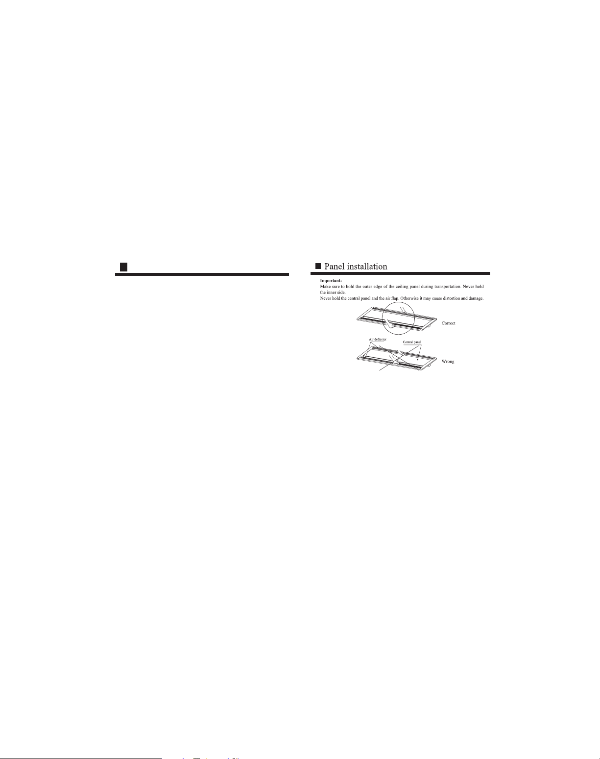
Panel installation 18 21
Caution
Auto Restart function for C MRV models
Haier Auto Restart function when the unit power drops down suddenly, the unit
microprocessor will store the previous working condition and when the power is on again,
the unit will run as this memory
Auto Restart function is designed basically on the MRV whole system, but it is suitable
for each indoor unit individually
If some of indoor units power cut down, but the outdoor unit and the other indoor units
still work, maybe problems will happen such as freezing at cooling mode and overload
protection at heating mode on those indoor units without power
Reason
When one or some indoor units power drops down and the other indoor units are still
work, the indoor units without the power, will keep the previous working condition before
the power is off And expansion valve keeps open at a kind of opening rate condition as
the previous requirement, so there is refrigerant flowing in the exchanger, but the indoor
fan stops working If the units work at cooling mode, the indoor units without the power
will maybe make freezing If the unit works at heating mode, maybe the outdoor unit
compressor will stop because of the pressure or temperature protection This is our design
basically on Auto Restart function currently
Haier, Herewith, solemnly informs our customers, installers, distributors, etc when making
installation, please make sure when the power is shut down whether artificially or
accidentally, the whole system including outdoor unit and all the indoor units must
be off. If you do not make the installation as our indication, Haier will not be responsible
for any problem resulting from this.
21

20
Safety Cautions
1
The following safety measures must be strictly followed
Keep these safety measures close at hand for timely references
After installation, trial run must be made to ensure normal operation Familiarize the user with the use
and maintenance through this manual
If the air conditioner is transferred to a new user, this manual should also be transferred
Please pay attention to the following:
Warning: Inappropriate use may lead to fatal or serious injuries
Caution: Inappropriate use may lead to bodily harm or mechanical damage; it may lead to serious
consequences in some cases
Any instructions with the sign of ì NOî shall be strictly followed, otherwise, it may cause me
chanical damage or endanger the safety of the user
Any instructions with the sign of ì STOPî shall be strictly followed, otherwise, it may cause me
chanical damage or endanger the safety of the user
Entrusted ins allation
Ins allation should be entrusted with after sale
servicemen Self installation is likely to cause
water leakage, shock and fire, etc
Ins allation should be done according to this install
ation manual Inappropriate installation may lead to
water leakage, shock and fire, etc
Connection of the earth wire
The earth wire should not be connected to gas pipes,
water pipes, lightning rods or telephone wires Poor
earth may lead to shocks
After sale servicemen shou d take measures to avoid
refrigerant eakage
Refrigerant leak may cause anox a when a certain
density is reached If the room is small, make sure o
have sound safety measures to avoid anox a acciden s
The installation of the elec ric part should be con
ducted by qualified professionals and done accord
ing to the installation manual Special return circuit
must be used Insufficient capacity return circuit and
inappropriate installation may lead to fire accidents
Installation site
The site must be firm enough to withstand the weight
of the air conditioner to prevent falling
During installation, if refrigerant leakage occurs,
ventilation measures must be taken When refrig
erant meets with fire, hazardous gas will be produced
After installation, make sure that there is no refriger
ant leakage
Refrigerant, if meeting with heaters and stoves, etc
in the room, may produce hazardous gas
Specific cables should be used for the wiring To avoid
external tension of the cables, the terminals should
be firmly fixed Inappropriate connection and fix ure
may lead to fire accidents
In order to discharge the condensed water, the
installation of the drainpipe should be done in
accordance with the manual instructions The
drainp pe should be treated for heat isolation
Inappropriate treatment may lead to water leak
age in the room
Electric leak breaker should be installed
Wi hout t, shock accidents may occur
Do not install at places where inflammable gas leak
may occur
Gas eakage may lead to fire accident
Caution
Warning

2
Indoor unit installation
19
18 3
Indoor unit installation
4
Indoor unit installation
Troubleshooting
17
93/94
11
12
14
17
18
1C
1d
1F
21
b5
b6
97
98
99
0C
Phenomenon
Running
continues
Running
continues
All stop
Running continues
All stop
All stop
All stop
All stop
All stop
All stop
All stop
Running continues
All stop
Running continues
Running continues
Stops
Runs
Outdoor interlocked input, including outdoorl unit and indoor PC board
Room temperature sensor (TA) circuit, including Room temperat
ure seasor (TA), indoor PC board
Indoor heat exchanger temperature sensor circuit (TC1/TC2), including indoor
heat exchanger temperature sensor (TC1/TC2) and indoor PC board
Indoor fan system, including revolution detecting circuit, indoor fan mo
tor and indoor PC board
Indoor unit, including PC board (EEPROM and peripheral circuit)
Converter overcurrent protection circuit, including G Tr, outdoor PC
board, converter wiring and compressor
Current sensor circuit, including current detecting circuit and outdoor
converter PC board
Outdoor defrosting sensor circuit, including outdoor defrosting sensor (TE)
and outdoor converter PC board
Outdoor unit, including outdoor interface control (I/F) PC board
Compressor system, including compressor lock and phase absence
Current detecting circuit, including power pressure and overload of refrig
erant circulation
High presure switch circuit, including high pressure switch and overload
of refrigerant circulation
Setting of indoor unit number and remote controller
Connecting wire, indoor PC board and remote controller
Center controlled address setting, including address setting (SW02),
central remote controller and indoor PC board
Center controlled communication circuit, including communication wire,
centralized controller, indoor power and indoor PC board
Outdoor abnormal input, including outdoor unit and indoor PC board
Fault
code
Reasons
Fault codes and reason
Troubleshooting
16
Confirm and verify
1 Press the ì Checkî switch on the remote controller for 1 2 seconds, ì Checkî will appear, and
the unit number and the error code will be displayed on the remote controller
2 The displayed number is the error unit number
3 Example is listed as follows:
Normal:
One error:
Two errors:
The signs will be displayed for a very short time If not seen clearly, press the ì Checkî switch again
When failure occurs, use the remote controller to display the corresponding error code
Checking
Fault codes and error place
Fault code
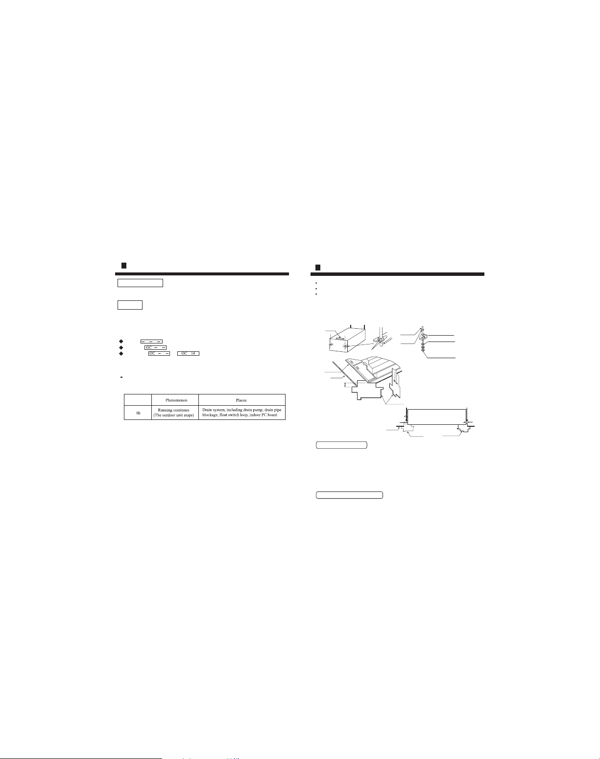
Put the nut on the screw bolt and suspend it on the T slot of the suspension part of the unit
Keep level of the body (within 5mm) with a gradoenter
Make sure and adjust the positions of the unit and the ceiling opening as well as the height
of the unit with the installation template
1 The bottom of the unit is 58mm from the lower ceiling surface (four corners)
2 Make sure that the front side of the indoor unit (tube side) is 95mm from the ceiling and the
back side of the unit (opposite side) is 35mm from the ceiling with the template
Installation of the panel
Mount the panel after tubing and wiring installation
Please refer to P18 21 of this manual for the panel installation
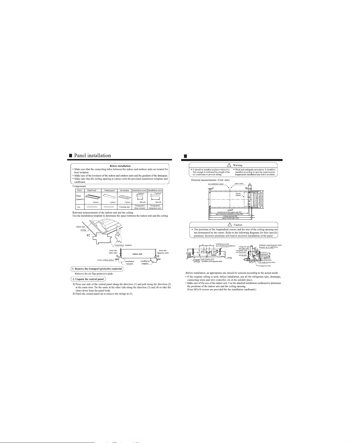
Before installation, make sure that the positions of the indoor unit and the ceiling opening
are correct
Requirements:
There is no space between the panel and the ceiling and between the panel and the indoor
unit, otherwise, dew or water leak may occur
Installation of remote controller
58
15
indoor unit
ceiling
installation template
front side
(tube side)
95
lower
ceiling
surface
indoor unit
35
back side
(opposite
s de)
Tighten the upper nut to fix the indoor unit
insta lation template
installation template
Please refer to the installation manual for the installation of the remote controller
5
Indoor unit installation
suspension screw
(M10)
tighten up w th a nut
gradienter
nut (M10)
parts other than M10 flat gasket a e
provided during installation
M10 flat gasket
M10 flat gasket
for safety, please mount according
to his diagram
nut (M10)

The indoor drainpipe should be treated for heat isolation
The indoor connections must have heat isolation Inappropriate isolation may lead to
dew forming
The drainpipe must have a falling gradient (above 1/100) and should not be made into
an ì Sî form, otherwise, it will produce noises
The horizontal length of the pipe should be shorter than 20m If the pipe is long, one
support should be set up for every 1 5 2m Avoid undulation of the pipe
Centralized piping is installed according to the following diagram
Never apply external forces on the connections of the drainpipe
To enable normal discharge of water, use drainpipes according to the installation manual To
avoid forming of dewdrops, it must be treated for heat isolation Inappropriate tubing may
lead to water leakage in the room
Caution
Requirements:
Pipe material
*
1.
5m~2m
solation
material
"S" shaped p pe
VP30
as large as possible(about 10 cm)
falling gradient
above 1/100
support
falling
gradient
(above 1/100)
Pipe material and isolation material
Unit attached parts
Isolation material
Hard PVC pipe 31 5mm (inner diameter)
Foam polyethylene thickness above 10mm
6
Indoor unit installation Trial operation
15
Before operation
Heating mode
Set the running mode to ì Heatî
Press the ON/OFF button till a blinking ì Hî and an ì Autoî sign appear on the wire controller Now
the unit enters into heating trial run
During forced trial run, working modes cannot be changed through the wire controller
After trial run, press the ON/OFF button to stop the unit
Trial operation
Refer to the service manual for the running procedure
When the unit fails to start under room temperature, try forced trial run by the following steps
Cooling mode
Set the running mode to ì Coolî
Press the ON/OFF button till an ì Lî blinks at the ì Setting Tempî area on the wire
controller LCD and ì Autoî is displayed at the fan speed area Now the unit enters
into cooling trial run
Before the unit is turned on, test the resistance between the power block terminal (L, N terminals) and
the earth If it is below 1M , it can't allowed running
Turn on the outdoor unit To protect the compressor during start up, it should be switched on 12 hours
in advance
Never operate the electromagnetic contactor manually for forced trial run (It is dangerous when the
protection device does not work )

14
Electrical wiring & Application control
7
Indoor unit installation

8
Warning
During installation, if refrigerant gas leakage occurs, ventilation measures must be taken When
refrigerant gas meets with fire, hazardous gas will be produced
After installation, make sure that there is no refrigerant leak
Refrigerant, if meeting with heaters and stoves, etc in the room, may produce hazardous gas
Allowable tube length and allowable height difference
Different units have different limits Refer to the attached manual
Pipe material and size
Material
Model
Pipe size
Gas side
Liquid side
Air conditioner used deoxidized phos copper (TP
2)
series 072 162
model
Refill refrigerant
Refer to the installation manual for the refilling of refrigerant A special meter should
be used for the filling of refrigerant and the filling must be in strict accordance with the specifications
R22:AB072 282FDAHA
R407:AB072 282FDBHA
Requirements:
Overfilling or underfilling may lead to compressor trouble The filling must be done
in strict accordance with the specifications
Connection of refrigerant pipes
Connect all refrigerant tubes before connection of the flare tube
Use two spanners for the indoor connection
Refer to the following table for the installation torque
Torque increase (N m)
Pipe external
diameter (mm)
Torque (N m)
series 182 282
model
Refrigerant piping
13
remote contro ler
D
Electrical wiring & Application control
()mm
15 88
9 52
12 70
6 35
6 35
11 8(1 2kgf m) 13 7(1 4kgf m)
9 52
15 88
24 5(2 5kgf m)
78 4(8 0kgf m)
29 4(3 0kgf m)
98 0(10 0kgf m)
12 70 490(5 0kgf m) 53 9(5 5kgf m)
19 05
98 0(10 0kgf m) 117 7(12 0kgf m)
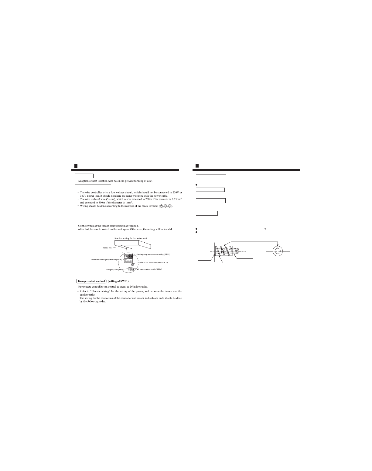
12
Set capacity (SW05)
Electrical wiring & Application control
Wiring hole
Remote controller wiring
Application control
9
Vacuum evacuation
Open all the valves
Open all the valves of the outdoor unit
Evacuate from the outdoor cut off valve with a vacuum pump
Never use encapsulated refrigerant in the outdoor unit for evacuation
Check the gas leaking
Check the joints and valve caps with a leakage detector or with soapsuds for gas leaks
Heat insulation
All the liquid and gas tubes must have separate isolation
During cooling run, temperature at both the liquid side and the gas side is low To prevent
dew forming, heat isolation must be made
Materials used for the tube isolation at the gas side must withstand 0 temperature
The joints should be treated for heat isolation
With cut edge up (Attached diagram)
Field tubing side
Auxiliary isolated tube
Indoor unit
Refrigerant piping

10
Caution
The specifications of the power circuit are listed in the table below Smaller capacity may cause
overheat or burnout
Power specifications
Electric leak breaker should be installed Without it, shock accidents may occur
To avoid danger, damaged cable must be replaced by professionals of cable makers or the like Wires
used by the indoor unit should be selected according to the installation manual
Never connect the block terminal in the control circuit (A, B, C, P, Q, X and Y) to a 220 230V or a
380 400V power line Otherwise, it may lead to mechanical damage or personal injury
Avoid contact of electric wires with high temperature pipes to prevent melting of the outer isolation
Wires should be made into a ì Uî shape after connected to the block terminal, and fixed with clips
Controlling wires may be laid and fixed together with the refrigerant tubes
If the supply cord is damaged,it must be replaced by the manufaturer or its service agent or a similar
qualified person
The wiring method should be in line with the local wiring standard
All the cables shall have got the European authentication certificate
The breaker of the air conditioner should be all pole switch,and the distance between its two contacts
should be no less 3mm Such means for disconnection must be incorporation in the fixed wiring
The power cable and connecting cable are self provided
Electrical installation should be entrusted with qualified servicemen and done in accordance with the
installation manual Special return circuit must be used Insufficient capacity return circuit and
inappropriate installation may lead to fire accidents
Specific cables should be used for the wiring To avoid external tension of the cables, the terminals
should be firmly fixed Inappropriate connection and fixture may lead to fire accidents
The unit must be earthed
The unit should be earthed properly Poor earth may lead to shocks The earth wire should not be
connected to gas pipes, water pipes, lightning rods or telephone wires
Warning
1) The type of connecting wire is shielded wire The type of the power cord is H07RN F(3G)
2) The wiring diagram refer to the wiring diagram on the indoor and outdoor units
NOTE:
AB072 282
FDAHA
AB072 282
FDBHA
Indoor un t
power
15A
H05RN F
3G1 5mm
2
5A/
250
V
AC
AC
220
230V
50Hz
2
500m<
1000m
2 5mm
2
L 50m
Manual
sw tch
23
< 500m
1 5mm
2
< 500m
1 5mm
2
< 200m
0 75mm
2
200m<
500m
1mm
2
Item
Model
Fuse
Connecting cable
Power w re (L)
Cent al contro ler
holding wire
Indoor & outdoor
commun cat on w re
Remote controller w re
Number of
cores
Core sec
tional area
Number of
cores
Core sec
tional area
Number of
cores
Core sec
tional a ea
Electrical wiring & Application control
11
Wiring should be done according to the number of the
block terminal,inappropriate connetction may lead to error
Indoor power wiring
The indoor and outdoor units should use separate special power lines
If several indoor units connect the same outdoor unit, the leak breakers and
switches of the indoor units should use the same power
Centralized controller communication wiring
The centralized controller communication wire are
non polarity 2 core wires (Fig 1)
To prevent electromagnetic disturbance, please use shielded wires
Remote controller wiring
The remote controller remote is polarized 3 core wires
The grouped wire controller wire (between the indoor and indoor
units) is polarized 2 core wires (Fig 2)
380 400V3N 50Hz
outdoor power
junc ion box
indoor un t
1PH 220 230V 50Hz
ea th
communica ion wire
shielding layer ear h
The shie d ng layer should be
connected together
(
shie d ng layer as isolation
)
leak b eaker manual witch
emo e cont o ler
grouped control
(
shielding layer as isolation
)
(
shielding layer as isolation
)
(
shielding layer as isolation
)
ndoor unit
shielding layer should be
connected ogether
central zed control signal w re earth
cen ralized con rol s gnal wire
(centralized cont o ler)
communication w re
leak breaker manual switch
ndoor power
1PH 220 230V 50Hz
ndoor unit
(cen ralized
controller)
spec ally used
by he power
remote controller
Wiring of indoor unit and outdoor unit
remote
con ro ler
Electrical wiring & Application control
 Loading...