

Page 1

Multi-Zone Technical Overview
ENGLISH
Table of Contents
Introduction ..................................................................................................................................... 2-11
Nomenclature ....................................................................................................................................................... 2
Specications .....................................................................................................................................................3-5
Safety Overview .................................................................................................................................................6-7
Functions & Controls....................................................................................................................................... 8-11
Outdoor Unit Technical Overview ................................................................................................... 12-33
Components ................................................................................................................................................. 12-18
Operations .................................................................................................................................................... 19-25
Testing ........................................................................................................................................................... 26-28
Error Codes ................................................................................................................................................... 29-33
Indoor Unit Technical Overview - Wall Mount ..................................................................................34-43
Components ................................................................................................................................................. 34-39
Testing ........................................................................................................................................................... 40-41
Error Codes ................................................................................................................................................... 42-43
Indoor Unit Technical Overview - Cassette ..................................................................................... 44-51
Components ................................................................................................................................................. 44-47
Testing ........................................................................................................................................................... 48-51
Indoor Unit Technical Overview - Slim Duct .................................................................................... 52-57
Components ................................................................................................................................................. 52-55
Testing ........................................................................................................................................................... 56-57
Wired Controller ............................................................................................................................ 58-64
Wireless Remote Controller ...........................................................................................................65-68
References......................................................................................................................................69-121
Troubleshooting,Resistance Values, Error Detection, Piping Length Limits ............................................ 69-72
Component Ratings ............................................................................................................................................ 73
Ductwork Installation ......................................................................................................................................... 74
Wiring ............................................................................................................................................................. 75-89
Piping Installation Dimensions ..................................................................................................................... 90-95
Flow Charts.................................................................................................................................................. 96-109
Sensors ...................................................................................................................................................... 101-121
TECHNICAL OVERVIEW
PAGE 1
Page 2

ENGLISH
1 U 18 LC 2 V H A
1 U 18 ES 2 V H A
Unit Type
A = Indoor Unit
1 = Single Zone Outdoor
2 = Two Zone Outdoor
3 = Three Zone Outdoor
4 = Four Zone Outdoor
NOMENCLATURE - Model Name Explanation
Nomenclature
Product Revision
Unit Type
U = Outdoor
B = Cassette Type Indoor
D = Slim Duct Type Indoor
M = Mid Static Duct Type Indoor
H = High Static Duct Type Indoor
W = Wall Mount Type Indoor
Nominal Capacity
In Btu/hr (x 1000)
Product Family
- MS
- LC
- SL
- SC
System Type
H = Heat Pump
C = Cool Only
Compressor Speed
V = Variable Speed
Voltage
1 = 115V
2 = 230V
PAGE 2
INTRODUCTION
Page 3

SPECIFICATIONS
Multi-Zone Indoor
ENGLISH
INTRODUCTION
PAGE 3
Page 4

ENGLISH
SPECIFICATIONS
Multi-Zone Indoor
PAGE 4
INTRODUCTION
Page 5

SPECIFICATIONS
Multi-Zone Outdoor
ENGLISH
INTRODUCTION
PAGE 5
Page 6

SAFETY OVERVIEW
Read These Safety Precautions
Be sure to read the safety precautions before conducting work. The items are classied into “Warning” and “Caution.” The
“Warning items are especially important since they can lead to death or serious injury if not followed closely. The “Caution”
items can also lead to serious accidents under some conditions if they are not followed. Therefore, be sure to observe all safety
ENGLISH
precautions listed here.
∆ This symbol means be careful when doing this procedure or touching this equipment.
ᴏ This symbol indicates a prohibited action.
• This symbol means that an action must be taken; the action will be listed next to the symbol.
After the repair work is complete, be sure to conduct a test operation to ensure that the equipment operates properly;
explain the safety precautions for operating the equipment to the customer.
Warning
Disconnect the power cable from electrical socket
before disassembling equipment for repair. Working
on equipment that is connected to a power supply
can cause an electrical shock.
If the refrigerant gas discharges during the repair
work DO NOT touch the discharging refrigerant gas.
The refrigerant gas can cause frostbite.
Before disconnecting the suction or discharge pipe
of the compressor at the welded section, recover
the refrigerant gas in a well-ventilated area. If
refrigerant gas remains inside the compressor, the
refrigerant gas or the refrigerating machine oil will
discharge when the pipe is disconnected and may
cause injury.
If the refrigerant gas leaks during the repair work,
ventilate the area. The refrigerant gas can generate
toxic gases when it contacts ames.
The step-up capacitor supplies high-voltage
electricity to the electrical components of the
outdoor unit. Be sure to discharge the capacitor
completely before conducting repair work. A
charged capacitor can cause electrical shock.
Be sure to use parts listed in the service parts
of the applicable model and appropriate tools to
conduct repair work. Never attempt to modify
the equipment. The use of inappropriate parts or
tools can cause electrical shock, excessive heat
generation, or re.
When relocating the equipment make sure that
the new installation site has sucient strenght to
withstand the weight of the equipment. If the new
installation site does not have sucient strength
and if the installation work is not conducted
securely, the equipment can fall and cause injury.
Be sure to install the product correctly by using the
standard installation frame provided. Incorrect use
of the installation frame and improper installation
can cause equipment to fall, resulting in injury.
Do not repair the electrical components with wet
hands. Working on equipment with wet hands can
cause electrical shock.
Do not clean the equipment by splashing water.
Washing the unit with water can cause an electrical
shock.
Make sure that the unit is grounded when reparing
the equipment in a wet or humid place to avoid
electrical shocks.
Be sure to turn o the power switch when cleaning
the equipment; the internal fan rotates at a high
speed and may cause injury.
Do not tilt the unit when removing it. Water inside
the unit can spill, wetting the oor.
Be sure to check that the refrigeration cycle section
has cooled down suciently before conducting
repair work. Working on the unit when the
refrigerating cycle is hot can cause burns.
Use the welder in a well-ventilated place. Using
the welder in an enclosed room can cause oxygen
deciency.
Be sure to use a dedicated power circuit for the
equipment; follow appropriate technical standards
for the electrical equipment, the internal wiring
regulations, and the instruction manual for
installation when conducting electrical work.
Insucient power circuit capacity and improper
electrical work can cause an electrical shock or re.
PAGE 6
INTRODUCTION
Page 7

SAFETY OVERVIEW
Read These Safety Precautions
Be sure to use the specied cable to connect
between the indoor and outdoor units. Make the
connections securely and route the cable properly
so that there is no force pulling the cable at the
connection terminals.
When connecting the cable between the indoor and
outdoor units make sure that the terminal cover
does not lift o or dismount because of the cable.
If the cover is not mounted properly, the terminal
connection section can cause an electrical shock,
excessive heat generation, or re.
Do not damage or modify the power cable.
Damaged or modied power cables can cause
electrical shock or re. Placing heavy items on the
power cable and heating or pulling the power cable
can damage the cable.
Do not mix air or gas other than the specied
refrigerant (R=4 10A/R22) in the refrigerant system.
If air enters the refrigerant system, an excessively
high pressure results, causing equipment damage
and injury.
If the refrigerant gas leaks, be sure to locate the leak
and repair it before charging the refrigerant. If the
leak cannot be located and the repair work cannot
be stopped, be sure to perform pump-down and
close the service valve to prevent the refrigerant
gas from leaking into the room. The refrigerant gas
itself is harmless, but it can generate toxic gases
when it contacts ames, such as fan and other
heaters or stoves and ranges.
When replacing the remote control battery, be sure
to safely dispose of the battery to prevent children
from swallowing it.
Do not install the equipment in a place where
there is a possibility of combustable gas leaks. If
combustible gas leaks and remains near the unit, it
may cause a re.
Be sure to install the packing and seal on the
installation frame correctly. If the packing and
seal are not properly installed, water can spill out,
wetting furniture and the oor.
ENGLISH
Replace power cables and lead wires if they are
scratched or deteriorated. Damaged cable and
wires can cause electrical shock, excessive heat
generation, or re.
Check to see if the parts are mounted correctly,
that the wires are connected correctly, and that
connections at soldered or crimped terminals are
secure. Improper installation and connections can
cause excessive heat generation, electrical shock,
and re.
If the installation platform or frame has deteriorated
or corroded, replace it. Corroded platform or frames
can cause the unit to fall, resulting in injury.
Check to make sure that the equipment is grounded.
Repair it if it is not properly grounded. Improper
grounding can cause an electrical shock.
Be sure to measure the installation resistance of
the repair. Be sure that the resistance is 1 M ohm
or higher. Faulty installation can cause an electric
shock.
Be sure to check the drainage of the indoor unit
after the repair. Faulty drainage can cause the water
to spill, wetting the furniture and the oor.
Important Safety Related
Installation Information
Indoor Clearances: If noncompliant may lead to temperature
control complaints.
Wire Sizing: If noncompliant may lead to communication errors
and inverter irregular operation.
Splices in Field Wiring: Splices between the wires that connect
between the outdoor and indoor unit should be avoided.
Communication errors may occur if noncompliant.
Sealing Penetrations: If penetrations at back of unit are not
sealed, unconditioned air may be drawn into the back of the
indoor wall mount unit. Temperature control and capacity
complaints may occur.
INTRODUCTION
PAGE 7
Page 8

OVERVIEW & INTRODUCTION
Functions and Controls
Auto Mode
When the running mode is turned to auto after starting the
ENGLISH
system, the system will rst determine the running mode
according to the current room temperature and then will
run according to the determined mode: Tr means room
temperature; Ts means temperature setting; Tp means
temperature of indoor coil pipe
Tr≥73°F Choose Cooling Mode
Tr<73°F Choose Heating Mode
After turning to the auto mode, the running mode will be
switched between cooling mode, fan mode, and heating mode
according to the change of the indoor ambient temperature.
There is a 15 minute delay between mode changes.
Cooling operation mode
Temperature control range: 60°F---86°F
Temperature dierence: ±2°F
* Control features: When Tr (input airow)>Ts (set
temperature) °F, the indoor fan will operate at the set speed,
the mode signal will be sent to the outdoor system, and
the compressor will start. When Tr (input airow)< Ts (set
temperature)°F, the indoor fan will operate at the set speed,
and the mode signal will be sent to the outdoor system, and
the compressor will stop. The system will keep the original
status if Tr= Ts.
Airow speed control: (temperature dierence ±2°F)
Automatic:
When Tr≤Ts +4°F high speed.
When Ts+2°F≤Tr<Ts+5°F, medium speed
When Tr<Ts+2°F, low speed
When the sensor is o, low speed
When the airow speed has no delay from the high to low
switching, the speed should be delayed for 3 minutes (remain
at high speed for 3 minutes.) before the next switch.
When the system is operating, you can set the high, medium
or low speed manually. (When the sensor is on or o, the
system will change the speed 2 seconds after receiving the
signal.)
*Louver control: the location for the louver can be set
according to your needs.
*Defrosting function: preventing the frosting on the indoor
heat exchanger (when cooling or dehumidifying). When the
compressor works continuously for 1 to 6 minutes (adaptable
in EEPROM) and the temperature of the indoor coils has been
below 32°F for 10 seconds, the compressor will be stopped
and the malfunction will be recorded in the malfunction list.
The indoor system will continue to run. When the temperature
of the indoor coil is raised to 45°F, the compressor will be
restarted again (the requirement of 3 minutes’ delay should
be satised.)
Dry Mode (Dehumidifying mode)
* temperature control range: 60---86°F
* temperature dierence: ±2°F
Control feature: Send the dehumidifying signal to the outdoor
system.
When Tr>Ts+4°F, the compressor will be turned on, the indoor
fan will operate at the set speed. When Tr is between the
Ts and Ts+4°F, the outdoor system will operate at the high
dehumidifying frequency for 10 minutes and then at the low
dehumidifying mode for six minutes. The indoor fan will
operate at low speed.
When Tr< Ts, the outdoor system will be stopped, the indoor
fan will be stopped for 3 minutes and then turned to the low
speed option.
All the frequency conversions have a ±2°F dierence.
* Wind speed control: Automatic:
When Tr≥ Ts+ 9°F, high speed.
When Ts+5°F≤Tr< Ts+9°F, medium speed.
When Ts+4°F≤Tr< Ts+5°F, low speed.
When Tr<Ts+4°F, light speed.
If the outdoor fan is stopped, the indoor fan will be paused for
3 minutes.
If the outdoor fan is stopped for more than 3 minutes and the
outdoor system still operates, the system will be changed into
light speed mode.
When the airow speed has no delay from the high to low
switching, the speed should be delayed for 3 minutes (remain
at high speed for 3 minutes.) before the next switch.
When the sensor is o or Tr< Ts+5°F, the manual operation can
not be made. (obligatory automatic operation.)
*Louver location control: the location for the louver can be set
according to your needs.
*Defrosting function: preventing the frosting on the indoor
heat exchanger (when cooling or dehumidifying). When the
compressor works continuously for 16 minutes (adaptable in
EEPROM) and the temperature of the indoor coils has been
below 32°F for 10 second, the compressor will be stopped and
the malfunction will be recorded in the malfunction list. The
indoor system will continue to run. When the temperature
of the indoor coil is raised to 45°F, the compressor will be
restarted again (the requirement of 3 minutes’ delay should
be satised.)
PAGE 8
INTRODUCTION
Page 9

OVERVIEW & INTRODUCTION
Functions and Controls
Heat Mode mode.
* temperature control range: 60---86°F
* temperature dierence: ±2°F
Control feature: the temperature compensation is
automatically added and the system will send the heating
signals to the outdoor system.
If Tr≤Ts, the outdoor compressor is turned on, the indoor
fan will be at the cold air proof mode.
If Tr>Ts+, the outdoor system is turned o, the indoor fan
will be at the heat residue sending mode.
If Tr<Ts+, the outdoor system will be turned on again, the
indoor fan will be in the cold air proof mode.
Indoor fan control
Manual Control: You can choose high, medium, low and
automatic speed control. Automatic:
When Tr<Ts, high speed.
When Ts≤Tr≤Ts+4°F, medium speed.
When Tr> Ts+4°F, low speed.
When the airow speed has no delay from the high to low
switching, the speed should be delayed for 3 minutes (remain
at high speed for 3 minutes.) before the next switch.
*Louver location control: the location for the louver can be set
according to your needs.
Cold air-proof operation
ENGLISH
4. During the cold air proof operation, the indoor system
will continuously send ‘indoor high speed’ signals to the
outdoor system.
* Residue heat sending. The indoor fan will send the
residue heat at a low speed for 12 seconds.
If other conditions are satised, when the compressor stops,
the indoor system will operate at a light speed. The indoor
fan will stop when the coil temperature is below the heat start
temp 4’.
* Defrosting. When the system receives the defrosting
signal from outdoors, the indoor fan will stop and the indoor
temperature display won’t change. At thistime, any indoor coil
malfunctions will be neglected. When the outdoor defrosting
nishes, the coil malfunction will still be neglected until the
compressor has been started up for 30 seconds. The indoor
temperature display will not change and the system operates
at the cold air proof mode.
* Automatic heating temperature compensation:
when the system enters the heating mode, the temperature
compensation (4) will be added. When the status is switched
o, the compensation will be erased.
Timing
You can set 24 hours on/o timing. After setting, the timing
indicator will be displayed. Also, the light will turn o after the
timing is set. The followings are several timing methods:
1. The indoor operation within 4 minutes after the start
up is as the following diagram, the air speed can be raised only
after the speed has reached a certain level.
2. 4 minutes after the start up of the indoor fan, the
light airow and the low airow will be turned to the set speed
airow.
3. In the cold air proof operation, the fan won’t stop
after the start up.
1. System ON timing: The timing indicator will be
displayed and the indoor system is under the waiting mode.
The light will be turned o when the timing is nished and the
rest of the system will operate under a normal condition. The
timing starts since the last reception of the timing signal.
2. System /OFF timing: When the system is turned on,
the timing indicator will be displayed; the rest of the system
will operate under normal conditions. When the set time
expires, the indicator display will turn o and the system will
turn o. If you have set the dormant functions, the order
of your settings will be operated according to the timing
settings.
3 . System ON/OFF timing: The settings will be
completed according to the settings.
INTRODUCTION
PAGE 9
Page 10

OVERVIEW & INTRODUCTION
Indoor Unit Operating Mode Conicts
Indoor System Mode Conict
The indoor unit is trying to operate in a mode that is opposite
ENGLISH
of the mode the outdoor unit is currently operating in. Change
the operating mode to either heat or cool, or the indoor unit
will shut o.
Abnormality conrmation approaches
1. Indoor temperature sensor abnormality:
Under the operation, the normal temperature ranges from
120°F to -30°F. When the temperature goes beyond this
range, the abnormality can be conrmed. If the temperature
goes back into the range, the system will automatically
resume.
2. Indoor heat interaction sensor abnormality:
Under the operation, the normal temperature ranges from
120°F to -30°F. When the temperature goes beyond this
range, the abnormality can be conrmed. If the temperature
goes back into the range, the system will automatically
resume.
Low Load Protection Control
In order to prevent the frosting of the indoor heat interaction
device, the outdoor system will be stopped if the indoor heat
interaction temperature is 32°F for 5 minutes, but the fan will
continue to operate. The outdoor system will be started again
when the heat interaction temperature is above 108°F, and the
system has been stopped for 3 minutes. The malfunction will
be stored in the malfunction resume and will not be revealed.
High Load Protection Control
The outdoor system will be stopped if the coil temperature is
above 149°F for 2 minutes. The indoor fan will be controlled by
the thermostat. The outdoor system can be restarted when
the coil temperature is below 108°F and the system has been
stopped for 3 minutes. The malfunction will be stored in the
malfunction resume and will not be revealed.
3. Indoor/Out door malfunction: When the indoor system
receives the outdoor malfunction codes, it will store the code
into E2 for the malfunction list resume. The indoor system
will continue to operate according to the original status, the
malfunction code will not be revealed or processed.
4. Transmission abnormality:
If the indoor system can’t receive the outdoor system for 8
minutes, the communication abnormality can be conrmed
and reported and the outdoor system will be stopped.
PAGE 10
INTRODUCTION
Page 11

OVERVIEW & INTRODUCTION
Multi-Zone Outdoor
When the compressor rst starts
The compresor will start in low frequency. After a brief time
delay, the compressor will come up to operating speed to
meet the demand requirement for capacity.
The outdoor fan control (exchange fan)
When adjusting the fan speed, the unit should remain at each
speed for 30+ seconds to avoid speed-change malfunctions.
In Cooling Mode, the wait time between speed levels should
be 15 seconds.
The outdoor fan control when in cooling or dehumidifying
mode
Five seconds after compressor starts, the outdoor fan will
start running at medium speed. After 30 seconds, it begins
to control the fans peed according to the temperature
conditions of the outdoor environment.
Multi-Zone Outdoor
The Control of the Outdoor Unit Expansion Valve
When unit starts, the EEV valves will energize and change to a
standard opening. When operation starts, the EEV will change
position to keep the suction vapor superheat level at around
10°F.
When the unit is shut o the opening size of the expansion
valve of the indoor unit is 5 steps;
Four-way valve control
For the details of defrosting four-way valve control, see the
defrosting process.
Under heating mode, the four-way valve opens. If the
compressor does not start or changes to a non-heating
mode, the compressor will be stopped for 2 minutes, and then
the four-way valve will shift.
ENGLISH
Over-temperature Heat Mode Indoor Coil
The over-temperature routine will protect the system from excessive high indoor coil temperature during heat mode operation.
The routine will initiate if the indoor coil temperature sensor reads temperatures in excess of 131F. Conditions that cause high
indoor coil temperature include indoor fan failure, dirty indoor coil and operating the system in heat mode when outdoor air
temperatures exceed operating limit. (Too warm outside)
Should this routine be initiated, the system will reduce compressor frequency until the indoor coil temperature reaches 117F.
Once this is achieved, the system will return to normal operation.
149°F
138°F
131°F
124°F
117°F
INTRODUCTION
PAGE 11
Page 12

Outdoor Unit Technical Overview
Outdoor Unit Technical Overview
The outdoor unit features a variable speed rotary type compressor that delivers refrigerant ow to up to 4 individual
ENGLISH
indoor units. The system uses R-410A refrigerant mixed with
PVE oil. The system is rated to operate at 208/230 volts single
phase 60 Hz power.
Indoor units compatible with this model include high wall type,
slim duct type and cassette type.
The indoor cassette unit can be controlled by either a remote
control or a wired controller. The indoor high wall unit is controlled by infrared remote. The slim duct unit is controlled by
wired controller only.
All indoor units must operate together in either heat mode,
or cool mode. The indoor units will not automatically switch
between heat and cool modes of operation. The rst unit that
is turned on and set to provide comfort, will set the operating
mode of the system. All other indoor units must now operate
in the same mode as the rst unit that was energized.
Introduction - Overview
Circuit Boards
The Circuit Boards
There are 4 control boards located in the outdoor unit. To access the boards, remove the top cover and the cover located to the
right of the outdoor fan motor opening. The boards are the Electronic Control Unit (ECU), Module Circuit Board (MCB), Power
Circuit Board (PCU) and Service Monitor Board (SMB).
Service Monitor Board (SMB)
Service Monitor Board (SMB)
The SMB has important features, including DIP Switches
that aect system operation, Digital Error Code Displays, Compressor Operating Frequency Display and
Diagnostic capability.
1
The SMB is connected to the ECU via Plugs CN-2
and CN-3.
2
The SMB DIP switch SW-1 should have all 4
switches in the OFF position. This setting will congure
the system for normal operation with variable speed
inverter control.
3
1
2
4
3
The digital display will indicate operating frequency of the compressor when no error code is present. If a system error
code occurs, the code will be displayed here.
4
There are 4 GREEN LED indicators that indicate the status of the wiring and communication links between the outdoor
unit and indoor unit. When lit GREEN, the wiring is correct.
PAGE 12
TECHNICAL OVERVIEW
Page 13

TECHNICAL OVERVIEW
Electronic Control Unit Circuit Board (ECU)
Electronic Control Unit Circuit
Board (ECU)
The Electronic Control Unit
operates the outdoor fan motor,
crankcase heater, EEV stepper
motors and the 4-way valve.
This board also controls the
general operation of the system
and makes all of the diagnostic
decisions. The ECU is connected
via communication cables to
the Module Circuit Board, Power
Circuit Board and the Service
Monitor Board.
1
Voltage to operate the
ECU is provided by the PCB on
terminals ACN and ACL.
2
When this power is present, the GREEN LED on the ECU should be lit.
11
12
ENGLISH
6
14
10
9
15
8
7
13
3
2
4
1
16
5
3
The communication cables to the PCB and MCB boards
connect via Plugs CN6 and CN-9.
4
The SMB connects to plugs CN-23 and CN-8. When
these cables are connected to the SMB, the SMB digital display should be illuminated.
5
Plug CN-21 connects the data path between each
indoor unit and the outdoor unit ECU board. The connections
from this plug terminate at the Number 3 terminal at the voltage connection terminal strips for the indoor units.
6
The Outdoor Fan Motor is a DC voltage variable speed
type that connects to the ECU at terminal Plug CN-11.
7
The 4-Way Valve is energized by line voltage from a
connection via Plug CN-5. This valve is energized in HEAT
MODE.
8
The Crankcase Heater is energized via a connection at
terminals CON-9 and CON-8 on the ECU.
9
The EEV Stepper Motors are controlled via connections
at terminals CN-15 through CN-20. These EEV Stepper Motor
connections include the connection for the HEAT MODE EEV
located at the outdoor coil.
10
Each EEV has a set of temperature sensors that monitor
the temperature of the exiting liquid and entering vapor from
each evaporator circuit. These sensors are mounted in a group
near the center of the circuit board.
11
There are 6 system temperature sensors that monitor
refrigerant line temperature and outdoor air temperatures.
These sensors plug into the ECU via 2 Plugs CN-14 and CN-7.
12
The system has two refrigerant pressure switches, a Low
Pressure Switch and a High Pressure Switch. These switches
are connected to the ECU via Plugs CN-12 and CN-13.
13
There are 3 sets of DIP Switches located on the circuit
board. They are SW-7. (Factory Settings Only), SW-5 (Defrost
Adjustments) and SW-6 (Not Currently Used).
14
There are 4 surface mounted buttons located next to
SW-5 and SW-6. These buttons are for factory use only.
15
The ECU board has two LED Indicators, a GREEN power
indicator and a RED Diagnostic Indicator LED. When power is
present, both the GREEN and RED LED lights are lit.
16
A 15A 250V rated ceramic fuse is located on the ECU. This
fuse will open if excessive current occurs or if a power surge is
present. This fuse is eld replaceable.
TECHNICAL OVERVIEW
PAGE 13
Page 14

Technical - OverviewOUTDOOR UNIT TECHNICAL OVERVIEW
Module Circuit Board (MCB)
Module Circuit Board (MCB)
1
ENGLISH
The Module Circuit Board generates 3 phase DC power
to operate the variable speed compressor. The compressor is
connected to the MCB via terminals CN-5. CN-6 and CN-7.
2
A Reactor Coil is connected to the MCB at terminals
CN-3 and CN-4. The Reactor Coil will lter out electrical noise
generated at high frequency operation. The ltering out of
electrical noise will prevent pin holes from being burned into
the compressor motor windings during high speed operation.
3
The MCB has 3 surface mounted LED indicators to aid
in diagnostics. The indicator LED colors are GREEN for Power/
Status, Red and Yellow for Diagnostic Codes.
4
The MCB generates heat that is transferred to a heat
sink located on the back of the board. The heat sink transmits this heat to the outdoor air. A temperature sensor Tm is
attached to the inverter semi-conductor chip.
5
The temperature sensor is connected to the MCB via
terminal CN-11. If excessive heat is detected by this sensor,
the system will stop operation and generate an Error Code 38.
The RED Diagnostic LED indicator located on MCB will ash 14
times. When the sensor cools o, the system will re-start and
the diagnostic error codes will clear.
6
There is a communication cable connected to the MCV
via Plug CN-9. The wire from this plug goes to a connection on
the ECU board. If this plug is disconnected or loose, the RED
Diagnostic LED located on the MCB will ash 14 times and the
system will shut o on an Error Code 04.
1
2
6
3
LEDs
4
5
Temperature Sensor
(located under board)
PAGE 14
TECHNICAL OVERVIEW
Page 15

Technical OverviewOUTDOOR UNIT TECHNICAL OVERVIEW
Power Circuit Board (PCB)
Power Circuit Board (PCB)
The purpose of the Power Circuit Board is to lter out potential electrical noise before it reaches the outdoor unit electronic circuits. All voltage to operate the outdoor unit circuits
must pass through the PCB.
1
A replaceable 25A 250V rated ceramic fuse protects
the outdoor unit electronics. The fuse would open if a power
surge or internal short in the outdoor unit occurred. This fuse
is eld replaceable.
2
The Power Circuit Board (PCB) receives line voltage
from the building power supply via a connection between the
Line Power terminal on the outdoor unit and the terminals P1
and P2 of the PCB.
3 4
connects to terminals P3 and P4. The Electronic Control Unit
receives power to operate via connections at terminals P5
and P6. The Compressor Module board receives power via
connections at terminals P7 and TERMINAL 3.
When power is available to the Electronic Control Board and
the Compressor Module board, their respective GREEN LED
indicators will be ashing if the unit is in standby, or continuously lit if the system is running. If the GREEN LED is not lit,
there may not be power to either the PCB or the board receiving power from the PCB. (The Power Control Board does not
have a power indicating LED.)
6
There is a communication plug labeled CN-1 on the
PCB. This plug connects from the PCB to the Electronic
Control Unit (ECU). If this cable is disconnected or loose, the
system will generate a Code 6 module low or high voltage
error. This error will not be displayed in memory on the indoor
unit wired controller.
5
The voltage that powers the indoor units
ENGLISH
6
6
Ground
2
1
5
25A 250V
4
Fuse
3
TECHNICAL OVERVIEW
PAGE 15
Page 16

ENGLISH
OUTDOOR UNIT TECHNICAL OVERVIEW
Outdoor Unit Components
4 Way Valve
Outdoor
Fan Motor
Outdoor Fan Motor
The Outdoor Fan Motor is a variable speed motor. The motor
is energized via a connection plug on the ECU. The motor
is powered by line voltage from the ECU. The motor has a
PWM circuit that feeds back voltage to the ECU. The ECU will
control the speed of the motor by a DC voltage applied to the
yellow wire of the connection plug. The feedback PWM signal
from the fan motor is applied to the ECU via the blue wire on
the connection plug.
Low
Pressure
Switch
4 Way Valve
The 4 Way Valve is energized during heating mode operation.
The valve is energized with 230 volts via a connection plug on
the ECU. When energized, the valve directs the compressor
hot gas to the indoor coil.
During Cooling mode and Defrost mode operation, the valve
is de-energized. When de-energized, the valve will direct the
compressor hot gas to the outdoor coil.
High
Pressure
Switch
Low Pressure Switch
The system has a Low Pressure Switch that will shut down
system operation if abnormally low refrigeration circuit
pressure is detected. This switch is connected to the ECU
via an electrical plug. During normal operation this switch
will be closed.
If the switch were to open during a call for cooling or heating
mode operation, the system will shut o the compressor
and display an error code. If the pressure rises to re-close
the switch, the compressor will re-start and continue on
with normal operation. Multiple cycles of opening and
closing the switch will cause the system to lock out and
display an Error Code 43.
Causes of low refrigerant pressure include leaks,
undercharging, restrictions, EEV failure and cold room air
temperatures/dirty indoor coils/restricted airow at indoor
unit.
PAGE 16
High Pressure Switch
The system has a High Pressure Switch that will shut down
system operation if abnormally high refrigeration circuit
pressure is detected. This switch is connected to the ECU via
an electrical plug. During normal operation this switch will be
closed.
If the switch were to open during a call for cooling or heating
mode operation, the system will shut o the compressor and
display an error code. If the pressure drops to re-close the
switch, the compressor will re-start and continue on with
normal operation. Multiple cycles of opening and closing the
switch will cause the system to lock out and display an Error
Code 42.
Causes of high refrigerant pressure include overcharging,
restrictions, EEV failure, and dirty outdoor coil.
TECHNICAL OVERVIEW
Page 17

OUTDOOR UNIT TECHNICAL OVERVIEW
Outdoor Unit Components
Compressor
The compressor is a variable speed dual rotary type compressor. The compressor has a built in accumulator to protect
against liquid oodback during running operation. A factory
supplied crankcase heater will protect the compressor from
o cycle liquid migration. Additionally, there is an oil separator
located in the outdoor unit that will aid in the return of compressor oil during both cooling and heating modes of opera-
tion.
The normal operating frequency of the compressor is between 20-95 RPS.
ENGLISH
When a call for cooling or heating occurs, the EEV will be positioned to a starting position. The starting position is based
upon the Outdoor Ambient Air Temperature. For example,
in cooling mode, at outdoor air temperature above 68°F, the
starting position of the valve will be 250 pulses. If the Outdoor
Air Temperature is lower than 68°F, the valve will be opened to
a position equal to 210 pulses.
The actual starting position of the valve is not something a
service technician can use to aid in solving a diagnostic problem. It is however, good to understand how these systems
fundamentally work.
When the compressor starts and the cooling or heating cycle
starts, the position of the EEV will be adjusted based upon the
Liquid and Gas Temperature Sensors that are associated with
each EEV. The EEV open position will be adjusted to try and
maintain around 10F of suction vapor superheat.
The ECU may also make an open or close adjustment to the
EEV based upon the temperature of the compressor hot gas
discharge line. If the line becomes too hot, or cool, the position of the EEV may be altered to ensure the compressor is
not damaged by a lack of refrigerant ow or liquid oodback.
The operation of the compressor is monitored by the ECU for
starting operation, suction line temperature and discharge
line temperature. Should an abnormal condition be detected,
the ECU will in some instances adjust the operational frequency of the compressor or may shut down system operation and display an appropriate Error Code.
EEV Valves
The metering devices used in the outdoor unit are EEV type
valves. The valve positions are controlled by electronic pulses
received from the ECU. These valves have potentially 500
steps. Each indoor unit has an EEV for cooling mode operation. The outdoor unit has 1 EEV that is used for heating mode
operation.
Crankcase Heater
The system has an option for a compressor crankcase heater.
The heater is powered by line voltage via a connection plug on
the ECU. The purpose of the heater is to keep the compressor
oil warm during o cycle periods. Warming the compressor
oil prevents liquid refrigerant from migrating into the compressor shell and mixing with the oil during periods where the
compressor is o.
The heater is energized during o cycle periods when the outdoor air temperature is below 90°F. During running operation,
the heater will be o.
TECHNICAL OVERVIEW
PAGE 17
Page 18

OUTDOOR UNIT TECHNICAL OVERVIEW
Outdoor Unit Components
Temperature Sensors Outdoor Unit
The outdoor unit has two groups of temperature sensors. The rst group of sensors are Liquid and Gas Sensors that are asso-
ENGLISH
ciated with each indoor unit EEV. These sensors monitor the leaving liquid temperature from the EEV and the returning Suction
Vapor temperature from the indoor units. The dierence between the two temperatures is used to calculate the operational
suction vapor superheat level of each calling indoor unit. These sensors are labeled Tc1 and Tc2 on the schematic drawing. They
plug into the ECU unit on a series of plugs located near the center of the circuit board.
The second group of sensors monitor key temperatures in the refrigeration circuit and outdoor unit. The sensors associated
with the refrigeration circuit include compressor discharge line temperature, compressor suction line temperature, outdoor
coil entering gas temperature, outdoor coil temperature cooling mode and outdoor coil heat mode temperature (Defrost). The
ambient outdoor air temperature is monitored by sensor Ta. The temperature of the heat sink attached to the Module Board is
monitored by Sensor Tm. These sensors connect to the ECU via plugs CN-7 and CN-14.
Outdoor Coil
Entering Gas
Temperature
Sensor
Compressor
Discharge Line
Temperature
Sensor
Outdoor Coil Cooling
Temperature Sensor
Outdoor coil
Heat Mode
Temperature
Sensor
(Defrost)
Module
Heat Sink
Temperature
Sensor
Compressor
Suction Line
Temperature
Sensor
PAGE 18
TECHNICAL OVERVIEW
Page 19

OUTDOOR UNIT SEQUENCE OF OPERATION
The outdoor unit is capable of controlling up to 4 individual indoor units. The outdoor unit will vary compressor capacity and
outdoor fan motor speed to match the demand requirement from the indoor units. All capacity and diagnostic decisions are controlled by the outdoor unit ECU. During any period where the outdoor unit is running, all indoor units must be in the same mode
of operation. If any unit is energized in a mode that opposes the rst indoor unit that was turned on and set to provide cooling or
heating, the opposing unit’s request will be ignored.
Throughout a call for either heating or cooling operation, the temperature sensors in the indoor and outdoor units will provide
critical temperature points to the outdoor unit ECU. If the temperatures being sensed are abnormal or trending to a level that is
potentially going to create overheating of the compressor or freezing of the indoor unit.
The frequency adjustments or system responses to temperature sensors readings are explained in the section Temperature
Sensor Responses.
Cooling Mode Sequence of Operation
Outdoor
heat
exchanger
temp.
sensor
EEV O
Low pressure
switch
Accumulator
Pipe sensor
Toci
Strainer
2
FAN-OUT
Distributor
4
Outdoor
ambient
temp.
sensor
Defrost
sensor
4-way valve coil:
OFF
ON
Indoor
heat
exchanger
temp.
sensor
FAN-IN
Indoor
ambient
temp.
sensor
Refrigerant flow in cooling
Refrigerant flow in heating
Indoor unit A
Indoor unit B
Indoor unit C
Indoor unit D
Indoor unit A
Unit A gas pipe temp. sensor
Unit B gas pipe temp. sensor
Indoor unit B
Unit C gas pipe temp. sensor
Indoor unit C
Unit D gas pipe temp. sensor
Indoor unit D
5
Unit A liquid pipe temp. sensor
Unit B liquid pipe temp. sensor
Unit C liquid pipe temp. sensor
Unit D liquid pipe temp. sensor
Strainer
Strainer
Strainer
Strainer
7
Suction temp.
sensor
Compressor
Discharge temp.
sensor
6
Gas stop valve
Oil
separator
High pressure
switch
5/8
1
Capillary tube
φ2.7*φ1.0*55in
4-way valve
3
EEV A
EEV C
EEV D
B VEE
Liquid stop vavle
3/8
valve
Receiver
Check valve
ENGLISH
On a call for cooling, the indoor unit will send the room temperature and set-point requirement to the outdoor unit ECU
via the data signal wire path. The data travels from the indoor
unit to the outdoor unit via the wire located on terminal 3.
The indoor unit’s louver will open and the indoor fan motor will
start.
The outdoor unit will energize the EEV’s that are controlling
refrigerant ow to the calling indoor units. The position of the
EEV valves will be set to a beginning position based upon the
outdoor air temperature.
The 4-way valve will be de-energized. After a 3 minute time
delay, the outdoor fan motor will be energized. Shortly after
the outdoor fan motor turns on, the compressor will start in
low frequency. The operating frequency of the compressor
will be displayed on the Service Monitor Board Display.
The refrigerant in the system will begin to ow. The compressor will discharge hot gas into the oil separator. Oil will be
trapped in the separator and returned to the suction inlet of
the compressor via the capillary tube assembly low pressure
path.
1
Temperature Sensor Td
The temperature of the compressor discharge hot gas will be
monitored by the Discharge Temperature Sensor. If the sensor
reads too hot or cool, the frequency/status of the operation will
potentially be altered.
The hot gas will leave the oil separator and enter the 4 way
OPERATIONS
PAGE 19
Page 20

OUTDOOR UNIT SEQUENCE OF OPERATION
Cooling Mode Sequence of Operation
valve. The 4 way valve will direct the hot gas to the outdoor
coil. The refrigerant will condense in the outdoor coil and be
slightly subcooled. The refrigerant is now in a liquid state.
ENGLISH
2
Temperature Sensor Toci
The temperature of the hot gas leaving the 4 way valve will be
monitored by the Toci Temperature Sensor. This temperature
should be near the temperature of the compressor discharge
gas temperature. If it is not, there is a problem with the 4 way
valve. The ECU will detect the temperature dierence and generate an Error Code.
3
Temperature Sensor Tc
This sensor monitors the temperature of the outdoor coil during
condensing operation. If abnormal condensing temperature is
detected this sensor, the outdoor fan motor speed or compressor frequency may be adjusted.
4
Temperature Sensor Ta
The outdoor air temperature will be monitored by the ECU. If the
outdoor air temperature rises or falls, the speed of the outdoor
fan/positions of the EEV’s may be changed.
The vapor refrigerant will then enter the 4 way valve and be
directed to the Compressor suction accumulator. The accumulator will trap any liquid refrigerant that may enter the
compressor and potentially damage it.
The vapor will exit the accumulator and enter the compressor.
The refrigeration cycle will continually repeat until the demand for cooling ends.
7
Temperature Sensor Ts
The temperature of the suction gas entering the compressor
is monitored by the Suction Temperature Sensor. If abnormal
temperature either hot or cool is detected, the frequency of the
compressor may be adjusted or the system may stop operation
to protect the compressor.
During the call for cooling, the indoor air temperature will get
closer to setpoint and demand will ease. The compressor will
reduce frequency as the demand decreases. Should an additional indoor unit call for cooling, the demand will increase and
the compressor speed will increase.
The refrigerant liquid will exit the outdoor coil and enter a
strainer where debris is trapped. The refrigerant liquid leaves
the strainer and bypasses the outdoor coil EEV via a path
through the check valve.
The refrigerant liquid now enters a receiver where excess
refrigerant will store. The required liquid leaves the outdoor
liquid receiver and passes through the Liquid Stop Valve.
After the liquid leaves the stop valve, it will enter the restriction of the CALLING INDOOR UNIT’s EEV. The EEV will drop
the pressure of the liquid to low pressure low temperature.
5
Temperature Sensor Tc2
The EEV associated Liquid Pipe Sensor will monitor the temperature of the refrigerant leaving the EEV to calculate system
superheat.
The low pressure low temperature refrigerant will enter the
mixed phase liquid line and travel to the indoor unit. Heat from
the air passing across the indoor unit evaporator will ash o
the cold refrigerant into a cold vapor.
The cold vapor will travel down the vapor line and return to the
outdoor unit via a path through the Gas Stop Valve.
When the temperature setpoint of the indoor units is met, the
indoor units will continue to run but the outdoor unit will shut
o. This is normal operation.
6
Temperature Sensor Tc1
The EEV Gas Pipe Sensor will monitor the temperature of the
suction gas to calculate the dierence between Liquid Pipe
Temperature and Gas Pipe Temperature. This calculation is the
suction vapor superheat. If a change in EEV port opening size is
needed, the EEV will make a small adjustment.
PAGE 20
OPERATIONS
Page 21

OUTDOOR UNIT SEQUENCE OF OPERATION
4-way valve coil:
OFF
ON
3
Indoor
heat
exchanger
temp.
sensor
FAN-IN
Indoor
ambient
temp.
sensor
Refrigerant flow in cooling
Refrigerant flow in heating
Indoor unit A
Indoor unit B
Indoor unit C
Indoor unit D
Heating Mode Sequence of Operation
Unit A gas pipe temp. sensor
Indoor unit A
Unit B gas pipe temp. sensor
Indoor unit B
Unit C gas pipe temp. sensor
Indoor unit C
Unit D gas pipe temp. sensor
Indoor unit D
4
Unit A liquid pipe temp. sensor
Unit B liquid pipe temp. sensor
Unit C liquid pipe temp. sensor
Unit D liquid pipe temp. sensor
Strainer
Strainer
Strainer
Strainer
ENGLISH
Outdoor
heat
exchanger
temp.
sensor
EEV O
Low pressure
switch
Accumulator
Pipe sensor
Toci
Strainer
6
FAN-OUT
Distributor
Outdoor
ambient
temp.
sensor
Defrost
sensor
5
7
Suction temp.
sensor
Compressor
Discharge temp.
sensor
2
Gas stop valve
EEV A
B VEE
EEV C
EEV D
Liquid stop vavle
Oil
separator
High pressure
switch
5/8
valve
3/8
Receiver
1
Capillary tube
φ2.7*φ1.0*55in
4-way valve
Check valve
On a call for heating, the indoor unit will send the room
temperature and set-point requirement to the outdoor unit
ECU via the data signal wire path. The data travels from the
indoor unit to the outdoor unit via the wire located on terminal
3. The indoor unit’s louver will open the indoor fan will remain
o.
EEV valves serving indoor circuits will step to a FULL OPEN
BYPASS position. Outdoor EEV valve serving outdoor coil
will step open to a pre-set metering position based upon the
temperature of the outdoor air.
The outdoor unit 4 way valve will be energized. Equalization
noise will be heard.
The outdoor fan motor will start.
The compressor will start in low RPS speed and gradually
speed up.
Indoor fan will begin to operate at slow speed and gradually
increase speed.
With the compressor operating, refrigerant will begin to ow
throughout the refrigeration circuit.
The operating frequency of the compressor will be displayed
on the Service Monitor Board Display.
When the compressor starts, the compressor will discharge
hot gas into the oil separator. Oil will be trapped in the
separator and returned to the suction inlet of the compressor
via the capillary tube assembly low pressure path.
1
Temperature Sensor Td
The temperature of the compressor discharge hot gas will be
monitored by the Discharge Temperature Sensor. If the sensor
reads too hot or cool, the frequency/status of the operation will
potentially be altered.
The hot gas will leave the oil separator and enter the 4 way
valve. The 4 way valve will direct the hot gas to ALL of the
indoor coils.
Note: Any indoor unit that is in heating mode will have it’s louver
open and indoor fan running. Non-calling indoor units will receive hot
gas but their fans will remain on very low speed with the louver open.
When demand for heat increases, the indoor fan will speed up to
meet the increased demand.
2
Temperature Sensor Tc1 and 3Indoor Heat Exchanger
Temperature Sensor
The temperature of Tc1 should now be hot. This will indicate
the 4 way valve is directing hot gas to the indoor coils. If it is not,
there is a problem with the 4 way valve. The ECU will detect the
temperature dierence and generate an Error Code.
OPERATIONS
PAGE 21
Page 22

OUTDOOR UNIT SEQUENCE OF OPERATION
Heating Mode Sequence of Operation
The indoor heat exchanger temperature sensor will monitor
the temperature of the indoor coil to ensure it is hot enough to
ENGLISH
prevent blowing cold air. Once adequately warm temperature is
sensed at the indoor coil, the ECU will energize the indoor fan to
a higher speed.
The hot gas entering the indoor coil will condense into a
saturated mix and then be subcooled. The refrigerant will
return to the outdoor unit via the mixed phase small line.
is monitored by the Suction Temperature Sensor. If abnormal
temperature either hot or cool is detected, the frequency of the
compressor may be adjusted or the system may stop operation
to protect the compressor.
During the call for heating, the indoor air temperature will
get closer to setpoint and demand will ease. The compressor
will reduce frequency as the demand decreases. Should an
additional indoor unit call for heating, the demand will increase
and the compressor speed will increase.
4
Temperature Sensor Tc2
This sensor monitors the temperature of the refrigerant liquid
returning from the indoor coil. If abnormally warm liquid is
sensed, the ECU will make inverter or indoor fan motor speed
changes to compensate.
The liquid will enter the Liquid Line Strainer and will pass
through the OPEN EEV
The refrigerant liquid now enters a receiver where excess
refrigerant will store.
After the liquid leaves the Liquid Receiver, it will enter the
restriction of the OUTDOOR UNIT’s EEV. The EEV will drop
the pressure of the liquid to low pressure low temperature.
Heat from the outdoor air will boil o the cold refrigerant.
The outdoor coil absorbs heat from the outdoor air. The
refrigerant vapor boiling from the liquid refrigerant in the
outdoor coil exits the outdoor coil.
5
Temperature Sensor Te
The outdoor coil temperature will be sensed by the Defrost
Sensor. The sensor will use this temperature to maintain EEV
position/superheat adjustment and to calculate when a defrost
cycle is necessary.
When the temperature setpoint of the indoor units is met, the
indoor units will continue to run but the outdoor unit will shut
o. This is normal operation.
6
Temperature Sensor Toci
This temperature sensor is now sensing the suction line
temperature of the refrigerant vapor leaving the outdoor coil.
This temperature is used in calculation of the required position
of the OUTDOOR UNIT EEV for proper superheat adjustments.
The vapor refrigerant will then enter the 4 way valve and
be directed to the Compressor suction accumulator. The
accumulator will trap any liquid refrigerant that may enter the
compressor and potentially damage it.
The vapor will exit the accumulator and enter the compressor.
The refrigeration cycle will continually repeat until the demand
for heating ends.
7
Temperature Sensor Ts
The temperature of the suction gas entering the compressor
PAGE 22
OPERATIONS
Page 23

OUTDOOR UNIT TEMPERATURE SENSOR RESPONSES
Outdoor Unit Control Information
10.2.1 Outdoor frequency control
A. The compressor running frequency is range is 20-95 RPS.
10.2.2 Electronic expansion valve (EEV) control
A: EEV SPECIFICATION: Maximum open angle is 500 pulses.
Driving speed is PPS.
B: Start-up EEV Conditional state
When the system is in the Cool/Dry mode, the standard open
angle of the EEV will be set at a position that is determined
by the temperature of the outdoor air. When the outdoor air
temperature is greater than 68°F, the initial setting of the EEV
will be 250 pulse open. If the outdoor air temperature is less
than 68°F, the EEV will open 210 pulses.
In Heating mode, the standard open position will be 250
pulses when the ambient air temperature outdoors is greater
than 50°F. If the air temperature outdoors is less than 50°F, the
open pulse rate is set to 210.
During running operation, the EEV position may be adjusted if
the compressor discharge gas temperature indicates a need
to supply more or less refrigerant to the evaporator circuit.
ENGLISH
10.2.4 Crankcase Heater Control
The crankcase heater is controlled by the ECU. The heater
keeps the compressor oil warm to prevent liquid refrigerant
from migrating to the oil during periods where the system is
not running. The heater will operate during o cycle periods
when the outdoor air temperature is below 80.6°F. When the
outdoor air temperature is greater than 90°F, the heater will
not be energized. When the compressor is running, the heater
will not be energized.
10.2.5 On Demand Defrost Logic
The system defrost function during heat mode is a demand
type system. Two temperatures are monitored by the ECU
to determine if defrosting is needed, they are Outdoor air
temperature Sensor Ta and Outdoor coil temperature Sensor
Te.
To enter a defrost cycle on demand, the system must be in
heat mode and the compressor must have run for 10 minutes
continuously and 45 minutes of compressor run time in heat
mode must have accumulated. If the following conditions
have been met for at least 5 continuous minutes, the system
will enter a demand defrost cycle:
Here are the control responses and EEV positional changes
that can occur due to either hot or cool discharge gas
temperature:
Valve Adjustments
Valve Adjustments Due To Hot Gas Discharge Temperature
Limits
If the discharge gas temperature rises above 212°F, the EEV
will open to its widest allowed position to try and reduce the
temperature of the compressor.
If the discharge temperature is greater than 194°F, but less
than 212°F, the EEV will not be adjusted.
If the discharge line temperature drops below 194°F, the EEV
will reduce its size to reduce refrigerant ow.
10.2.3 4-way valve control during heating mode
If the 4 way valve fails to switch the hot gas ow to the indoor
coil during a call for heat, the system will enter a protection
routine. If the indoor coil average temperature is below 59°F,
10 minutes after the compressor has started, and stays there
for at least 1 minute, the system will lock out and display a
4-way valve protection fault error code.
Sensor Te must sense a temperature that is less than or equal
to:
Te< CxTa-a
C is calculated as follows:
If Ta < 32°F then C=.8 If Ta> 32°F then C=.6
a is set by SW5-2 switch Factory setpoint is 8
Opposite Switch setting is 6
If the system is in an area that is easy to frost, it is
recommended to set the SW5-2 switch to opposite setting
and change the value of a to 6.
Example: Te = 26°F Ta = 44°F C=.8 a = 8
Solution: 26°F 44 x .8= 35.2-8=27.2 26°F is colder than
27.2°F so the system defrost cycle starts.
The system can only remain in defrost for up to 10 continuous
minutes of run time. The defrost cycle will terminate if sensor
Te reaches 44.6°F for a period of 60 seconds or 53.6°F for
a period of 30 seconds. In either case, the defrost cycle will
terminate after 10 minutes.
OPERATIONS
PAGE 23
Page 24

(Td)
is too high
Co
de
s
g
e
p
1.0 I
0.95I
0.93I
0.90I
0.88I
0.85I
Stop immediately, if abnormal stop 3 times in 1 hour, the
unit will stop and alarm.
Reduce FQY rapidly 2HZ/S
Reduce FQY rapidly 1HZ/S
Reduce FQY slowly 1HZ/10S
Remain FQY
Increase FQY slowly 1HZ/10S
OUTDOOR UNIT TEMPERATURE SENSOR RESPONSES
Forced Defrost Operation
10.2.6 Forced Defrost Operation
The system can be placed into a forced defrost cycle from the
wired controller. The system will remain in defrost until sensor
ENGLISH
Te has sensed 53.6°F for at least 1 minute or until the defrost
cycle has reached 10 minutes total runtime.
A forced defrost cycle can be initiated with the compressor
o. The system will enter a 3 minute time delay prior to
energizing the compressor.
10.2.7 Defrosting Time Flowchart
beginning end
fixed frequency indicated FQY 60s defrosting FQY 80 Hz(E) 60s soft startup
compressor
outdoor motor ON send defrosting signal to indoor Auto
4-way valve ON
all EEVs auto open angle auto open angle
all indoor motors ON
10.2.8 Frequency Control and Compressor Discharge Line
Temperature
If the temperature of the discharge line gets too high, and
the EEV adjustment cannot correct the problem, the ECU will
make frequency adjustment to the speed of the compressor
in an attempt to cool it down. The chart here shows the
adjustment steps versus the discharge line temperature.
Multi:
248 ℉
239 ℉
230℉
Discharging temp. TD
221℉
212℉
203℉
0HZ 0HZ
OFF
OFF 15s
OFF anti-cold air func tion
5s
450-pulse 450-pulse
350-pulse(E)
If keeping for 10s, the unit stops, 3 minutes later, the unit can
re-startup. If in 60 minutesthe unit occurs alarm for 3 times, the
failure can be eliminated.
Reduce FQY rapidly 2HZ/S
Reduce FQY rapidly 1HZ/S
Reduce FQY slowly 1HZ/10S
Remain FQY
Increase FQY slowly 1HZ/10S
10.2.8 Frequency Control when there is CT Over-current
Protection
Stop immediately, if abnormal stop 3 times in 1 hour, the
1.0 I
0.95I
0.93I
0.90I
0.88I
0.85I
unit will stop and alarm.
Reduce FQY rapidly 2HZ/S
Reduce FQY rapidly 1HZ/S
Reduce FQY slowly 1HZ/10S
Remain FQY
Increase FQY slowly 1HZ/10S
10.2.9 High Pressure Protection
If abnormally high refrigerant circuit condensing pressure is
detected, the high pressure switch will open. The outdoor unit
will initiate an Error Code and stop compressor operation. If
the system pressure drops enough to re-close the switch the
system will re-start. If the failure occurs 3 times, the system
will lock out and display the appropriate Error Code.
High condensing temperature can also cause high pressure.
The ECU will monitor the temperature of the condensing coil
in both heating and cooling modes of operation. Frequency
adjustments will be made to the compressor speed in an
attempt to manage high pressure that can be caused by dirty
condensing coils and high heat loading. The chart below shows
the ECU frequency response at high condenser temperatures.
(Indoor Coil Heat Mode, Outdoor Coil Cool Mode)
Keep for 5 seconds, stop to alarm, after 3-minute standby, the
unit can restartup. In 60 minutes it occurs 3 times continously,
156℉
154℉
.
m
t
151℉
in
n
147℉
n
144℉
140℉
unit will stop to alarm and the failure can be resumed after being
electrified again.
Reduce FQY rapidly 2HZ/S
Reduce FQY rapidly 1HZ/S
Reduce FQY slowly 1HZ/10S
Remain FQY
Increase FQY slowly 1HZ/10S
10.2.10 Low Pressure Protection
The system low pressure switch is normally closed. The
switch will open when the refrigerant pressure gets too low.
Typical causes are refrigerant leaks/undercharging and low
evaporator heat loading. The system will auto re-start if the
switch re-closes after opening. If the switch opens 3 times in
60 minutes of running, the system will display an error code.
PAGE 24
The low pressure switch is checked even when the system
is o. This protects the compressor against operating with a
great loss of refrigerant when the system has been o for a
long time.
OPERATIONS
Page 25

OUTDOOR UNIT TEMPERATURE SENSOR RESPONSES
·When unit stops, the reason that system still checks the low pressure : in a long time stop, make
protection for the compressor on the condition of great refrigerant leakage.
·The reason that low pressure switch action time is 30 seconds: when compressor stops, low pressure
does not change, so it will be shorter than the set time in operation.
(3) When compressor starts up, in 8 minutes, low pressure switch signal will be shielded.
(4) In defrosting, low pressure switch will be shielded.
(5) In oil return procedure, low pressure switch will be shielded.
(6) In the refrigerant discharging procedure after the oil return in cooling is over, low pressure switch will
be shielded.
In addition, the system will control low pressure through the evaporator temp. TE to realize the low
pressure protection function.
Forced Defrost Operation
10A, the frequency of the compressor decreases at the speed
of 0.1HZ/second.
ENGLISH
There are times when the switch is not active. The periods of
inactive switch operation are:
1. When the compressor starts up the switch will be o
for 8 minutes.
2. When the system is defrosting the switch is not
active.
3. In the oil return cycles the switch is not active.
4. In the refrigerant discharging procedure after the oil
return in cooling is over the switch is not active.
The system will recognize cold evaporator temperatures as a
likely condition where the low pressure switch may open. The
ECU uses the Te sensor in heat mode and the Tc2 sensor in
cooling mode to monitor the temperature of the evaporator
circuit. If abnormally cold coil temperatures are detected,
the ECU will reduce the compressor operating frequency to
prevent potential low pressure switch trips. The charts below
show the frequency versus evaporator circuit temperature
relationships.
In cooling, confirm through Tc2AVE:
-13℉
-22℉
TinAVE
-31℉
-40℉
-49℉
In heating, confirm through defrosting temp. Te:
Te
-22℉
-31℉
-40℉
-49℉
-58℉
Normal operation
Min. running FQY 20HZ
SV2 OFF & 20HZ
SV2 ON & 20HZ
Keep for 5 seconds, unit stops and alarm
occurs. 3 minutes later, restart up. If i
occurs 3 times in 1 hour, it will always
alarm and stop, electrify again a nd failure
will be cleared.
Normal operation
Min. running FQY 20HZ
SV2 OFF & 20HZ
SV2 ON & 20HZ
Keep for 5 seconds, unit stops and
alarm occurs. 3 minutes later, restart
up. If it occurs 3 times in 1 hour, it will
always alarm and stop, electrify again
and failure will be cleared.
Preventing Compressor Overcurrent
During compressor start-up, if the AC current is greater
than 9A, the frequency of the compressor increases at the
prohibited speed.
During compressor start-up, if the AC current is greater than
8A, the frequency of the compressor increases at the speed
of no faster than 0.1HZ/second.
The protection function of AC current:
• During the starting process of the compressor, if the AC
current is greater than 15A, the frequency of the
compressor decreases at the speed of 1HZ/second.
• During the starting process of the compressor, if the AC
current is greater than 13A, the frequency of the
compressor decreases at the speed of 0.1HZ/second.
• During the starting process of the compressor, if the AC
current is greater than 11A, the frequency of the
compressor increases at the prohibited speed.
• During the starting process of the compressor, if the AC
current is greater than 10A, the frequency of the compressor
increases at the speed of no faster than 0.1HZ/second.
When the outdoor ambient temperature is high, there’s
compensation for AC current protection.
t
When the outdoor ambient temperature is higher than 104°F,
AC current protection value decreases by 10AD
When the outdoor ambient temperature is higher than 115°F,
AC current protection value decreases by 15AD
When the outdoor ambient temperature is higher than 122°F,
AC current protection value decreases by 20AD
Antifreezing protection of the indoor heat exchanger
Prevents freeze-up of the indoor coil.
During compressor start-up, if the current of the compressor
is greater than 17A for 3 seconds, the compressor will stop
and alarm. After 3 minutes, the compressor will restart. If this
occurs 3 times in 20 minutes the compressor will stop, lock
out, and display an error code. Power must be removed from
the system to clear the code.
During compressor start-up, if the AC current is greater than
12A, the frequency of the compressor decreases at the speed
of 1HZ/second.
During compressor start-up, if the AC current is greater than
OPERATIONS
Outdoor coil
Heat Mode
Temperature
Sensor
(Defrost)
PAGE 25
Page 26

OUTDOOR UNIT TESTING PROCEDURES
Blue Viole t Yellow O range Red
Blue 47 Ω 46 Ω 46 Ω 46 Ω
Viol et 92 Ω 92 Ω 92 Ω
Yellow 91 Ω 91 Ω
Oran ge 91 Ω
Red
EEV Stepper Motor Resistance Values
Compressor Testing
If the compressor fails to start, the compressor may have an
internal electrical failure, the compressor may be seized mechanically, or the Module Control Board (MCB) may be bad.
ENGLISH
To test for a bad failed compressor, perform the following test:
EEV testing
The EEV metering devices are stepper type valves that have
up to 500 potential positional changes. The electrical coil that
is installed on the end of the EEV body rotates a magnetic
eld that opens and closes the valve. If the valve has failed, it
is either stuck in position or the electrical coil has an internal
problem.
1. Disconnect power and allow 10 minutes. Restore
power and call for normal operation. If the compress sor starts, the system may have been in a protection
mode that prevented the compressor from running.
If the compressor does not start, continue on with
testing.
2. Disconnect power. Wait 10 minutes for the capacitors
on the MCB to electrically discharge.
3. Unplug the compressor motor windings terminals
from the MCB.
4a-4d. Ohm the windings through each combination of leads
to determine if there is an open winding. If a winding is
open, replace the compressor. If the windings are
good, check each motor winding lead for a short to
ground. If the compressor winding is shorted to
ground, replace the compressor. If the motor checks
out good, continue on with testing.
3
4a
To test for an electrical coil problem, perform the following
test:
1. Disconnect power to the outdoor unit.
2. Unplug the suspect EEV coil from the connection plug
at the ECU.
3. Using an ohmmeter, check the ohms of all combina tions of windings.
4. Compare measured Ohms against the chart shown
below.
5. Replace the EEV coil if the ohm range is not correct.
6. If the OHM range is correct, yet the EEV does not
click/pulse open or closed when it should, check for a
mechanically stuck EEV.
7. Move the EEV coil to another EEV circuit to see if the
coil will operate the other EEV. If it works, the EEV
valve is stuck and must be replaced.
8. Always reset power when working with EEV valves
to reset any temperature sensor logic that may be
keeping the EEV from being energized during normal
operation. (Freezing etc.)
2
4b
4c
4d
PAGE 26
3
4
TESTING
Page 27

OUTDOOR UNIT TESTING PROCEDURES
Outdoor Fan Motor Testing
If the outdoor unit fan motor does not run or the Service Monitor board indicates an error code of
09, check the following voltages at connector CN11 on the outdoor unit ECU board. Set the meter
to read DC volts with a minimum voltage range of 350 volts. All voltage values are approximate.
Initiate forced cooling. (Press and hold the power button for 10 seconds on the wired controller.)
1) DC voltage between the Red and Black wires on the CN11 plug should read
310 ~ 334VDC. (This is the main voltage for powering the fan motor)
2) DC voltage between the White and Black wires on the CN11 plug should read
15VDC. (This is the voltage for powering the electronic circuit of the fan motor)
3) DC voltage between the Yellow and Black wires on the CN11 plug should read
4VDC. The voltage will read 0VDC when the fan is not being called to operate. (This is the
control voltage for regulating the speed of the fan motor)
4) DC voltage between the Blue and Black wires on the CN11 plug should read
8VDC. The voltage will read 14VDC when the fan is not being called to operate.
(This is the feedback voltage to the ECU board for determining the speed of the
fan motor)
If the outdoor fan initially runs, increases speed and then stops, and the Service Monitor board indicates an error code of 09, the feedback circuit is not functioning. Check that the wiring and plug
connections are secure.
1
ENGLISH
Outdoor Fan 310VDC
Pins 1 - 3
2
Outdoor Fan 15VDC
Pins 3 - 4
3
Outdoor Fan Control
Pins 3 - 5
4
Outdoor Fan Feedback
Pins 3 - 6
4 way valve testing
The 4 way valve will control the direction of hot gas discharge via an
internal slide assembly. The valve has a line voltage solenoid that is energized when heat mode operation is desired. The solenoid will direct
the internal slide to send the hot gas to the indoor coil. During cooling
mode de-energized operation, the internal slide will direct compressor hot gas to the outdoor coil.
4 way valves may have a failure of the electrical solenoid that prevents the valve from shifting, or they may become stuck due to debris
lodging inside the valve body. If the valve fails to direct the hot gas in
the proper direction, temperature sensors within the outdoor unit will
detect the problem and generate an Error Code.
If the valve fails to shift the hot gas to the proper coil, or it only partially shifts, perform the following test:
1. Make sure the system has proper charge.
2. Place the system in heat mode and call for heat. After a time delay, the valve solenoid should be energized by the ECU.
Check for line voltage to the solenoid.
3. If the valve has voltage but fails to shift the hot gas to the indoor coil, shut the system down and unplug the 4 way valve
from the ECU electrical plug.
4. Use an Ohmmeter to check for continuity through the solenoid coil. Check If the coil checks out good, but the valve will
not shift, the 4 way valve is bad. Replace the valve.
5. If the coil checks out bad, replace the coil.
6. Note partial shifting of the valve can be detected by
measuring the temperature of the suction gas where it enters the reversing valve and then comparing that temperature
to the temperature of the suction gas exiting the 4 way valve. There should be no more than 13°F dierence between entering
suction gas temperature and leaving suction gas temperature. Excessive temperature rise through the suction gas path is an
indication of a partial sliding valve. The temperature rise detected is due to hot gas bleeding through the slide assembly into the
suction side of the system. Replace the 4 way valve.
TESTING
PAGE 27
Page 28

OUTDOOR UNIT TESTING PROCEDURES
Temperature sensor testing
The temperature sensors are negative coecient type. These
sensors will reduce their electrical resistance as temperature
decreases. Should the sensors fail, the ECU will generate an
appropriate Error Code.
ENGLISH
To check the calibration of the sensors:
1. Shut o power to the outdoor unit.
2. Disconnect the sensor at the circuit board plug.
3. Measure the temperature of the air surrounding the
sensor.
4. Measure the electrical resistance of the sensor. Do
not force leads into sensor plug.
Restricted/Sticking Outdoor Unit Check Valve Test
The Check Valve allows refrigerant to ow freely around the
outdoor unit heat mode EEV during cooling mode. The valve is
a one directional device. The check valve has an internal steel
ball that will allow refrigerant to bypass or it will backseat and
block refrigerant ow.
In heating mode this valve will backseat to force liquid
refrigerant to ow into and through the Heat Mode EEV.
If the check valve sticks, the refrigeration cycle will experience
malfunction. Depending upon the mode of operation, a
sticking check valve may bypass the outdoor EEV and ood
the outdoor coil, or it may force liquid refrigerant through the
outdoor EEV during heating mode and cause a restriction.
How to test a check valve
1. With the system running in cooling mode, the
valve should ow refrigerant freely past the EEV. Take
the temperature of the liquid entering and leaving
the check valve. If there is a large temperature drop,
the check valve is partially restricted. If the
temperature of the liquid refrigerant into and out of
the check valve are the same, the valve is freely
owing liquid. If the valve is restricted, replace it.
5. Compare the measured resistance of the sensor
against the specication resistance/temperature
limit listed in the reference table in this manual.
6. If the sensor resistance is outside of the specication
tolerances shown on the resistance/temperature
table, replace the sensor.
2. In heating mode, the valve should block refrigerant
ow and force the liquid into the outdoor unit
Heating Mode EEV. Check the temperature of the
liquid entering and leaving the check valve. If the
valve is working properly, there should be warm liquid
at the entrance to the valve and cold refrigerant at
the exit. If there is no temperature dierence, the
valve is allowing liquid to bypass the EEV. Replace the
check valve.
PAGE 28
TESTING
Page 29

OUTDOOR UNIT ERROR CODES
Outdoor Unit Error Codes
If the ECU generates a system ERROR CODE, the code will be
displayed on the outdoor unit numeric display. Additionally,
error codes generated by the outdoor unit will be displayed
on the indoor unit circuit boards. The codes displayed on the
indoor unit circuit boards will be represented by ash codes
on LED indicators. The error codes displayed on the indoor
unit consumer display will not match the outdoor unit code
numbers. When performing diagnostic service, it will be necessary at times to use both codes to solve problems.
Sensor Error Codes
The easiest problems to solve will involve codes that are
related to potential failure of temperature sensors. Common
problems may include loose connections, open electrically,
and out of calibration. Checking the condition of the sensors
requires a temperature probe and an ohmmeter.
The Reference Section of this manual contains temperature
resistance tables that can be used to check the calibration
of the sensors. The measured resistance must be within the
tolerances printed on the top of the tables.
Testing Procedure (See temperature sensor testing on page
18)
To test the electrical condition of a temperature sensor perform the following:
1. Conrm the sensor is rmly attached to the circuit
board connection plug.
2. Remove the sensor wires from the connection plug
by releasing holding tension on the plugs tension tab.
3. Use an ohmmeter to test the electrical resistance of
the sensor.
4. If the sensor is within calibration, the sensor is good.
If the sensor is out of calibration, replace the sensor.
Outdoor Unit Temperature Sensor Error Codes
There are 15 potential Error Codes that can be generated by the ECU to indicate a failure of an outdoor unit temperature
sensor. Indoor unit temperature sensor failures will not be detected nor diagnosed by the outdoor unit ECU.
Error Code 10
This code indicates an electrical failure of the sensor that is
used to sense the temperature of the outdoor coil during
heat mode operation. This sensor is connected to the ECU via
a connection at Plug CN-14.
plugs near the center of the circuit board. (Note that if the
sensor has failed, and there is an unused port on the unit
available, the sensor from the unused port can be used to
temporarily x the problem.)
Error Code 38
ENGLISH
Error Code 11
This code indicates an electrical failure of the sensor that is
used to sense the temperature of the suction gas that enters
the compressor. The sensor is connected to the ECU via two
wires at Plug CN-14.
Error Code 12
This code indicates an electrical failure of the sensor that is
used to sense the temperature of the outdoor air. The sensor
is connected to the ECU via two wires at Plug CN-14.
Error Code 13
This code indicates an electrical failure of the sensor that is
used to sense the temperature of the compressor hot gas
discharge line. The sensor is connected to the ECU via two
wires at Plug CN-14.
Error Code 28-36
All of these codes indicate a failure of either a Liquid or Gas
Temperature Sensor that is part of either the A, B, C, or D
EEV circuit. Refer to the outdoor unit Error Code Decal for
specic identication of the malfunctioning temperature
sensor. These sensors connect to the ECU at connection
ERROR CODES
This code indicates a potential failure of the MODULE Board
temperature sensor. This sensor connects to the ECU via
Plug CN-14. This sensor is mounted near the heat sink
attached to the circuit board. A momentary power outage
where the sensor has cooled may also trigger this error code.
Test the sensor. If it tests go Outdoor Unit Pressure Switch
Malfunction Codes
There are two pressure switches in the outdoor unit, a low
pressure switch and a high pressure switch. They connect to
the ECU via plugs CN-12 and CN-13. The low pressure switch
is connected at CN-12 and the high pressure switch at CN-
13. A low pressure error will generate an Error Code 44. A high
pressure error will generate an Error Code 45.
Error Code 39
This code indicates an electrical failure of the sensor that is
used to sense the temperature of the outdoor coil. The sensor is connected to the ECU via two wires at Plug CN-14.
Error Code 41
This code indicates an electrical failure of the sensor that is
used to sense the temperature of the refrigerant entering or
leaving the outdoor coil. The sensor is connected to the ECU
via two wires at Plug CN-7.
PAGE 29
Page 30

OUTDOOR UNIT ERROR CODES
Pressure Switch Error Codes
Outdoor Unit Pressure Switch Error Codes
There are two pressure switches in the outdoor unit, a low pressure switch and a high pressure switch. They connect to the
ENGLISH
ECU via plugs CN-12 and CN-13. The low pressure switch is connected at CN-12 and the high pressure switch at CN-13. A low
pressure error will generate an Error Code 44. A high pressure error will generate an Error Code 45.
Low
Pressure
Switch
High
Pressure
Switch
Testing Procedure
If the system generates one of these codes, it is very unlikely that the switch is actually bad, it is much more likely that the
refrigeration system pressures are either too high or too low. The vapor line connection can be used to measure the high pressure during heating mode operation and low pressure during cooling mode operation.
There are no pressure ports that can be accessed to measure low pressure in heat mode nor high pressure in cool mode. If the
system trips on one of these errors where pressure cannot be measured, it is going to be necessary to remove system charge
and re-charge to conrm low or high charge is not causing the problem.
Error Code 43 or 45
Typical Causes of High Pressure In Cool Mode
• Overcharge
This code is indicating that system pressure is too low. Refer
to the detailed information on sensor responses for more
• Dirty Outdoor Coil
• Restriction (Not Likely)
information.
Typical Causes of High Pressure In Heat Mode
Typical Causes of Low Pressure Cool Mode
• Lack of charge (hot compressor)
• Low Heat on Indoor Coil (Cool Compressor)
• Overcharge
• Undersized Refrigerant Lines/Exceeding Length
• Restriction (Not Likely)
• Restriction (Not likely)
Note: If the refrigerant pressures are correct, yet the system
Typical Causes of Low Pressure Heat Mode
• Cold outdoor air (Running system in very cold air.)
does not close the error reporting pressure switch, replace
the defective pressure switch.
• Lack of charge (Hot Compressor and Indoor Coil)
• Restriction (Not Likely)
Error Code 42 or 44
The system is operating at excessive refrigerant pressure. If
the system is a new installation, it is likely that the charge is
too high. Refer to the reference section for installation and
charging procedure. (Note the Weight Method is the ONLY
way to charge this system. )
ERROR CODESPAGE 30
Page 31

OUTDOOR UNIT ERROR CODES
Indoor Unit and Outdoor Unit Communication Errors
Error Code 15
This error indicates the indoor unit and outdoor unit are having a problem communicating information. The wiring path for
the data signal is between Terminals 3 to 1 on the Terminal Blocks connecting the indoor unit to the outdoor unit. If the path
is correct, the GREEN LED on the Service Monitor Board should be lit. Check the wiring on ECU Plug CN-21 to the individual
Indoor Unit Terminal Blocks to ensure there are no loose connections. If OK, make sure the wiring size between indoor and
outdoor units is 14 gauge AWG Stranded Wire. Check that no twists in the wires/wire nuts are present in the wires between
indoor unit and outdoor unit Terminals 1 and also 3. (These are data path wires.) Reference Section Service Monitor Board
Test.
Error Codes Caused by Abnormal Refrigeration Circuit Conditions
Error Code 8
This code indicates the temperature of the compressor hot gas is too high. This error would have occurred despite the ECU
attempt at reducing operating frequency. Causes of this type of condition are typically a lack of refrigerant in the system,
excessive heat in the conditioned space or a restriction in the refrigeration circuit.
Error Code 16
This error code indicates the system may lack refrigerant. Recover the system charge and check charge level.
Error Code 21
ENGLISH
This code indicates the indoor coil has frosted over. Typically this condition will be due to a lack of heat in the conditioned
space, operating the indoor unit at excessively cold air temperature or a blockage of air ow to the indoor unit. (Failed indoor
fan motor.) This condition will cause the system to try and enter an anti freezing cycle. Refer to the Temperature Sensor
Response section for details.
Outdoor Error Code Related to INDOOR UNIT Operation
Error Code 21
This code indicates the indoor coil sensor has detected a coil temperature that is too cold. Refer to Temperature Sensor
Responses for diagnostic details. Likely causes are a lack of heat in the space. (Frost is a normal condition.)
Error Code Related to the ECU Board Operation
Error Code 1
The ECU board CPU can not read or write data. Replace the ECU Board.
ERROR CODES
PAGE 31
Page 32

OUTDOOR UNIT ERROR CODES
Error Codes Related to the MODULE Board Operation
Error Codes Related To The MODULE Board Operation
ENGLISH
Error Code 2
The module board detected excessive instantaneous current
compressor , IPM hardware automatically stopped the
Module Board output to protect the compressor.
Potential causes include:
• overcharge
• dirty outdoor coil
• hot conditioned space
• temperature/high load
• refrigeration circuit restriction
• seized compressor
• Bad Module Board
Error Code 4
This code indicates the Module board is not communicating
with the ECU. Check the wiring Plug connection between
the two control boards. Make sure the connection is tight.
The Module Plug connection is Plug CN-9 and the ECU plug
is also Plug CN-9. If the connection is good, yet the boards
do not communicate and the code will not clear, replace the
MODULE Board.
If the line voltage from the power company is correct, check
the output voltage of the Power Circuit Board. This voltage
connects to the MODULE board at terminals CN-1 and CN-2.
If the voltage is not within specications shown above,
replace the Power Circuit Board.
Error Code 18
Module board detected unstable to ow to the compressor.
The power output to the compressor will be stopped to
protect the compressor motor windings.
Error Code 5
This code indicates the Module board is working very hard
to operate the compressor. The most likely cause of the
compressor overworking is refrigerant overcharge. Recover
the refrigerant charge. Weigh the proper charge into the
system and retry operation.
Error Code 6
This code indicates the operating voltage of the system
is either too high or too low. Check line voltage for proper
limits. The line voltage supplied to the outdoor unit should
be now lower than 187V when the compressor starts. The
running voltage should be no lower than 197V. The incoming
line voltage to the outdoor unit should never be higher than
253V. If improper voltage is present, check the supply voltage
circuit from the building for proper size wiring and good
connections. If the voltage is still outside operating limits,
contact the power company to have the service corrected.
Possible causes include:
• Line voltage spike
• Poor line voltage supply
Error Code 23
This code indicates the temperature of the MODULE Board
is too hot. This error was generated by a temperature
sensor located on the MODULE Board heat sink. Causes of
overheating are typically overcharge of refrigerant, or very
hot operating temperatures.
Error Code 25
The electrical current ow in the Module is too high.
• Possible Causes: Hard starting compressor
• Refrigeration circuit overcharge
• Refrigeration circuit restriction
• Compressor Seized
• Excessive high load in conditioned space
• Running system in heat mode at high outdoor air
temperature
ERROR CODESPAGE 32
Page 33

OUTDOOR UNIT ERROR CODES
Error Codes Related to MODULE Board Operation
ENGLISH
Error Code 26
CPU module reset indicates possible drive module power
anomalies. Usually when the low line voltage conditions are
present. Check for line voltage problems.
Error Code 27
Compressor current abnormal: module driver board
detected the
that compressor current is too large, The Module board
software protects it and compressor.
Error Codes Related to Compressor, Outdoor Fan, 4-Way Valve
Error Codes Related To Compressor, Outdoor Fan Motor,
4-Way Valve
Error Code 9
This code indicates the outdoor fan motor is not running.
The fault is detected very quickly by the ECU. The system
will shut o and display this error code. If this error occurs,
reference the Test Procedure for Outdoor Fan Motor.
Malfunction Code 17
Possible Causes:
• overcharge
• dirty outdoor coil
• hot conditioned space temperature/high load
• refrigeration circuit restriction
• seized compressor
• Bad Module Board
4-Way Valve
This error code indicates that the 4 way valve is not directing
hot gas to the proper coil. In other words, the system is
running the refrigerant in the wrong mode of operation.
Refer to the Test Procedure for 4 way valve to diagnose the
problem.
Error Code 24
This error code indicates the compressor failed to start when
a call for operation occurred. Refer to the Test Procedure for
Compressor troubleshooting to diagnose the problem.
Compressor
ERROR CODES
PAGE 33
Page 34

Indoor Unit Technical Overview
INDOOR UNIT TECHNICAL OVERVIEW
Indoor Wall Mount Unit Components
5
ENGLISH
Display
6
Evaporator
Coil
4
Pipe
Sensor
Return Air
Temperature Sensor
Control
Board
7
Vertical Louvers
3
Stepper Motor
The wall mounted units act as evaporator coils during cooling
mode and condenser coils during heating mode. These units
have gravity condensate drain systems. If a condensate pump
is needed, it must be eld provided and mounted external to
the indoor unit.
The wall mount unit is shipped with a wireless
controller.
1
Power to operate the indoor unit comes from the
1
electrical line voltage terminal block at the outdoor
unit. The wiring includes 4 wires: 1, 2, 3 and ground.
Wires 1 and 3 complete the data path. These wires
should always be 14 gauge AWG Stranded type wire.
Splices in wires 1 or 3 may cause communication
errors.
2
The indoor unit features a multi-speed blower motor
2
that will change speed to match the capacity demand from
the outdoor unit. Separate motors located in the indoor
unit control the operation of the motorized louvers. All of the
louver motors are controlled via commands received from the
remote control. The blower motor is controlled by both the
remote control and by commands from the outdoor unit ECU.
Refer to the Remote Control Information in the Reference
section for louver control/remote procedures.
3
3
Terminal
1
Block
Fan
2
Motor
Horizontal Louver
3
Stepper Motor
Unlike typical air handlers found in the US market, these
units have metering devices located in the outdoor unit. The
metering devices are EEV type that are controlled by the
outdoor unit ECU.
Temperature sensors located within the wall mount
unit include a pipe temperature sensor and a return air
temperature sensor. The pipe temperature sensor is used
to sense the temperature of the indoor coil in both cooling
and heating modes. The return air sensor senses the
temperature of the air being drawn into the wall mounted unit
from the conditioned space. The operating functions of these
sensors is explained in the Temperature Sensor Function
section of this manual.
6
The indoor unit has a display that communicates system
6
mode, room temperature and diagnostic code information.
The diagnostic code information shown on the indoor unit will
NOT be the same code that is displayed on the outdoor unit.
When servicing a diagnostic error, compare the indoor unit
code to the outdoor unit code to make diagnostic decisions.
Codes that relate to outdoor unit problems should use the
outdoor unit display information as priority.
7
The indoor unit circuit board controls the switching
7
functions of the indoor unit. All control decisions are made
by the outdoor unit ECU. The indoor board has some limited
diagnostic capability which will be covered in this manual.
4
4
5
5
PAGE 34
TECHNICAL OVERVIEW
Page 35

INDOOR UNIT TECHNICAL OVERVIEW
Indoor Wall Mount Unit Circuit Board
The Indoor Unit Circuit Board communicates
with the outdoor unit ECU via a connection at
Terminal Block screw 3.
The data pulse that sends the communication information can be measured with a
voltmeter placed to DCV range. From the
ground connection at the Terminal Block to
the Number 3 screw connection, the voltage
should pulse up and down when data is being
transmitted.
This control board has control over the fan
louver movement, manual fan blower control,
indoor coil temperature and indoor air temperature sensing functions. All operational
decisions are controlled by the OUTDOOR
UNIT ECU. The connections on the indoor
indoor board are shown here in the schematic
drawing.
Fan Motor
7
3
3.15A 250V
Fuse
ENGLISH
CN21
CN52
Vertical Louvers
2
LED
Receiver / Display
Temperature Sensors
1
Horizontal Louver
Stepper Motorr
6
Stepper Motor
5
4
Line voltage to power the indoor unit comes in on Terminal
Block connections 1 and 2. Power connects from these terminal connections to CN- 52 and CN-21 on the circuit board. If
the board does not respond to commands and has no display,
check for line voltage at these connections. When power is
present at the indoor board, the RED LED on the circuit board
will blink a 2 ash code.
The control board has a replaceable 3.15A 250V fuse that
protects against excessive current. If power is present at
the board but the board does not work, check for continuity
through the fuse. Replace if the fuse is open.
The indoor unit temperature sensors are connected at Plug
CN6. When testing the calibration of these sensors, the wires
can be released from the plug by pressing on the tension tab
on the side of the plug.
There are two to three motors that control the movement of
the louvers right, left and up/down. These motors connect at
CN5, CN11 and CN10. Some units will use one motor to operate the right and left movement function.
The blower motor is connected to the circuit board at plug
CN-9.
There is an Emergency Run switch on the edge of the indoor
board that will put the system into Auto Mode should the remote control break or be lost. When this switch is pressed and
held for 5 seconds, the indoor unit display will beep twice and
the system will enter TEST MODE.
Emergency Run
Switch
The receiver/display unit that is mounted to the front cover of
the indoor unit plugs into the circuit board via a connection at
Plug CN-7.
TECHNICAL OVERVIEW
PAGE 35
Page 36

INDOOR WALL MOUNT UNIT TECHNICAL OVERVIEW
Blower Assembly
The blower assembly consists of a plastic blower wheel that
is connected to a variable speed indoor blower motor. A set
screw holds the blower wheel to the blower motor.
ENGLISH
The indoor blower motor is a DC Fan Motor that is
connected to the indoor unit control board via Plug CN-9.
The wiring from the motor to indoor board consists of 5 wires
connected to pins 1, 4, 5, 6 and 7. Pin 1 should have 310 VDC.
Pin 4 is ground. Pin 5 +15VDC. Pin 6 is the feedback signal. Pin
7 is the speed control.
During normal operation, the indoor control board will
energize the indoor blower motor and request proper speed.
The indoor blower motor will control the speed via a command
at the Pin 7 speed control. Proper fan speed is veried by the
indoor control board via the voltage level at the feedback
signal on Pin 6. Should the feedback signal not be present
during a call for indoor blower, the indoor control board will
indicate a Malfunction Code E14.
Temperature Sensors
The Piping Temperature Sensor senses indoor coil
temperature in the cooling mode and in the heating mode.
This sensor is used for Anti Freezing and Anti Cold Blow cycles.
The sensor also provides critical temperature information
to the ECU that may be used in frequency adjustments. See
Temperature Sensor Functions.
Indoor Pipe Sensor
The Ambient Temperature Sensor senses room
temperature. This sensor provides room temperature
information to the ECU for calculation of inverter capacity and
temperature control.
Indoor Ambient
Temperature Sensor
Louver motors
The louver motors are stepper type motors that move
the louvers either right/left or up/down. The motors are
controlled by pulsed voltage that cannot be measured. If the
louver does not move when it should, check for a blockage
in the louvers. If the louver is free to move, refer to the Test
Procedure Section.
See A and B below.
A
PAGE 36
Both sensors are negative temperature coecient type that
reduce electrical resistance as temperature rises.
B
TECHNICAL OVERVIEW
Page 37

INDOOR WALL MOUNT UNIT TECHNICAL OVERVIEW
Test Procedures
Accessing components/removing cover
1. To access components for service, rst disconnect
power to the outdoor unit. This will de-energize the
indoor unit.
2. Lift the front cover by prying on the two indented
nger holds at each end of the indoor unit.
3. Remove the three Phillips head screws located near
the bottom of the indoor unit. These screws are
located directly below the bottom of the air lter.
ENGLISH
6. Open the 3 caps that cover the screws located behind
the bottom of the louver. These caps ip up.
7. Remove the three screws located behind the caps.
4. Remove the lters.
5. Manually open the louver.
8. Remove the two screws that hold the digital display
to the front cover. The display can hang free.
9. Release the air temperature sensor from the clip that
holds it.
10. Pull upward on the top of the indoor unit cover to free
it from the four retaining clips. The cover will pivot
downward. The cover should now pull away from the
indoor unit.
TESTING
PAGE 37
Page 38

INDOOR WALL MOUNT UNIT TECHNICAL OVERVIEW
If the indoor fan motor does not run.
Indoor Fan Motor Voltage Check
1. Remove the front cover and access the circuit board connection CN-9.
ENGLISH
2. Reset power and turn the remote control fan command to Fan On mode.
Motor Test
1. If the motor doesn’t run, check for 310VDC between Pins 1 and 3. If it is not present, the indoor
board is bad. If voltage is present, continue on.
2. Check the voltage between Pins 3 and 4. The voltage should be +15VDC. If it is not present, the
board is bad. If voltage is present, continue on.
3. Check for voltage between Pins 3 and 6. If no DC voltage is present, the board is bad. If voltage is
present, change the motor.
Replace the Blower Motor
Replace the Blower Motor
Step 1. Disconnect the power.
Step 2. With the indoor unit cover removed, remove the two
screws on the left plastic evaporator coil bracket.
Step 4. Remove the two screws that hold the
electrical box in place.
310VDC
Pins 1 - 3
15VDC
Pins 3 - 4
Motor Feedback
Signal
Pins 3 - 6
Step 3. Remove the cover from the electrical box on the right
side of the indoor unit.
PAGE 38
Step 5. Lift and swing the electrical box out of
the way.
TECHNICAL OVERVIEW
Page 39

INDOOR WALL MOUNT UNIT TECHNICAL OVERVIEW
Step 6. Remove 6 screws that hold the motor bracket and
evaporator coil.
Step 7. Lift the evaporator coil and remove the motor
bracket.
Step 9. Unplug the motor from the circuit board.
ENGLISH
Step 10. Lift and slide the motor away from the
blower wheel.
Step 8 Loosen the motor shaft set screw. Phillips head
screw.
Step 11. Remove the two black anti vibration mounts from
the defective motor and place them on the new
motor.
Step 12 Install new motor in reverse order.
TECHNICAL OVERVIEW
PAGE 39
Page 40

INDOOR WALL MOUNT UNIT SECTION
Testing Temperature Sensors and Louver Motors
Testing Temperature Sensors
The easiest problems to solve will involve codes that are
related to potential failure of temperature sensors. Common
ENGLISH
problems may include loose connections, open electrically,
and out of calibration. Checking the condition of the sensors
requires a temperature probe and an ohmmeter.
The Reference Section of this manual contains temperature
resistance tables that can be used to check the calibration
of the sensors. The measured resistance must be within the
tolerances printed on the top of the tables.
To test the electrical condition of a temperature sensor
perform the following:
1. Conrm the sensor is rmly attached to the circuit
board connection plug.
2. Remove the sensor wires from the connection plug
by releasing holding tension on the plugs tension tab.
Testing Louver Motors
If the louver does
not operate with
command from the
remote control,
either the indoor
board is bad, or
the louver motor is
defective. It is more
likely the motor is
defective than the
board. (Make sure the louver assembly is not binding and
keeping the vanes from moving.)
1. Remove power from the unit and remove the indoor
unit cover.
2. Access the circuit board.
3. Use an ohmmeter to test the electrical resistance of
the sensor.
4. Measure the air temperature near the sensor and
compare the required resistance against
measured resistance. (See chart in reference section)
If the sensor is within calibration, the sensor is good.
If the sensor is out of calibration, replace the sensor.
(Tube Sensors should be removed from socket and
exposed to air temperature during test.)
3. Identify on the schematic drawing the inoperable lou ver motor and disconnect the plug from the circuit
board. (The up down louver motor is located on the
right side of the indoor unit. The left right louver mo-
tor is located bottom center. )
4. Use an Ohmmeter to test the electrical continuity
of the louver motor windings. The proper resistance
for each winding can be found in this table. If the mo
tor winding resistance is erratic or shows open, the
motor is defective. Replace the motor.
PAGE 40
5. If the motor checks out good, replace the indoor
control board.
TESTING
Page 41

INDOOR WALL MOUNT UNIT SECTION
Testing Communication Circuit
Testing Communication Circuit
If an Error E7 occurs, perform the following test to determine
if the indoor control board is functioning properly to send data
to the outdoor unit.
Perform this test with the unit powered and all wiring
connected between indoor and outdoor unit.
Make sure all wiring between the indoor and outdoor unit
are correct. There should no splices between the indoor and
outdoor unit wiring connecting terminals 1 or 3. Make sure
wiring is correct, before performing this test.
1. Measure the DC voltage between terminals 1 and 3
on the indoor terminal block.
Antifreezing Protection
Antifreezing Protection
Prevents freeze-up of the indoor coil
The indoor unit coil temperature sensor will shut o the
outdoor unit and begin a defrosting routine if the indoor coil
is below 32°F for more than 2 minutes. The indoor unit will
not report this operation. Once the indoor coil warms up, the
system will re-enter cooling mode and operate normally, This
protection cycle prevents the indoor coil from developing ice
coating during low heat load operation.
ENGLISH
2. The voltage should uctuate between 8VDC and
23VDC. The uctuating signal indicates a
good communication path.
3. If the voltage does not uctuate, and the wiring is
good, the indoor board is defective.
Indoor Coil Sensor
TESTING
PAGE 41
Page 42

INDOOR WALL MOUNT UNIT
Indoor Unit Error Codes
Indoor Unit Error Codes (HSU218VHG Only)
ENGLISH
The error codes that are displayed on the indoor units
may vary from the outdoor unit codes. The information
communicated by the error code will be the SAME for both
indoor and outdoor units even though the numbers may
dier.
Error Code E7
This code is indicating the indoor and outdoor units have lost
communication signal. Check wiring between indoor and
outdoor unit. Conrm 14 gauge AWG stranded wire present.
Conrm no splices in wires 1 and 3. Go to Test Procedures to
solve communication error.
Error Code E1
This code indicates a failure of the room temperature sensor.
Go to Test Procedure section to solve.
• refrigeration circuit restriction
• seized compressor
• Bad Module Board
Error Code F22
Compressor current abnormal: module driver board detected
that the compressor current is too large, The Module board
software protects it and the compressor.
Possible Causes:
• overcharge
• dirty outdoor coil
• hot conditioned space temperature/high load
• refrigeration circuit restriction
• seized compressor
• Bad Module Board
Error Code F3
Error Code E2
This code indicates a failure of the Pipe Temperature Sensor
on the indoor unit. Go to Test Procedure section to solve.
Error Code E4
This error indicates an EEPROM Error indoor unit control
board. Reset power. If error repeats, replace the indoor circuit
board.
Error Code E14
This code indicates the indoor fan motor failed to run. Go to
Test Procedure Section to solve.
Error Code F12
This code indicates an OUTDOOR UNIT EEPROM error. Cycle
power. If the error does not clear, replace the ECU.
Error Code F1
The module board detected excessive instantaneous current
compressor , IPM hardware automatically stopped the
Module Board output to protect the compressor.
This code indicates the Module board is not communicating
with the ECU. Check the wiring Plug connection between
the two control boards. Make sure the connection is tight.
The Module Plug connection is Plug CN-9 and the ECU plug
is also Plug CN-9. If the connection is good, yet the boards
do not communicate and the code will not clear, replace the
MODULE Board.
Error Code F19
This code indicates the operating voltage of the system
is either too high or too low. Check line voltage for proper
limits. The line voltage supplied to the outdoor unit should
be now lower than 187V when the compressor starts. The
running voltage should be no lower than 197V. The incoming
line voltage to the outdoor unit should never be higher than
253V. If improper voltage is present, check the supply voltage
circuit from the building for proper size wiring and good
connections. If the voltage is still outside operating limits,
contact the power company to have the service corrected.
If the line voltage from the power company is correct, check
the output voltage of the Power Circuit Board. This voltage
connects to the MODULE board at terminals CN-1 and CN-
2. If the voltage is not within specications shown above,
replace the Power Circuit Board.
Potential causes include:
• overcharge
• dirty outdoor coil
• hot conditioned space temperature/high load
Error Code F27
This error code indicates the compressor failed to start when
a call for operation occurred. Refer to the Test Procedure for
Compressor troubleshooting to diagnose the problem.
ERROR CODESPAGE 42
Page 43

INDOOR WALL MOUNT UNIT
Indoor Unit Error Codes
ENGLISH
Error Code F4
This code indicates the temperature of the compressor
hot gas is too high. This error would have occurred despite
the ECU attempt at reducing operating frequency. Causes
of this type of condition are typically a lack of refrigerant in
the system, excessive heat in the conditioned space or a
restriction in the refrigeration circuit.
Error Code F8
This code indicates the outdoor fan motor is not running. The
fault is detected very quickly by the ECU. The system will shut
o and display this error code. If this error occurs, reference
the Test Procedure for Outdoor Fan Motor.
Error Code F21
This code indicates an electrical failure of the sensor that is
used to sense the temperature of the outdoor coil during heat
mode operation. This sensor is connected to the ECU via a
connection at Plug CN-14.
Error Code F7
This code indicates an electrical failure of the sensor that is
used to sense the temperature of the suction gas that enters
the compressor. The sensor is connected to the ECU via two
wires at Plug CN-14.
Error Code F6
Error Code F11
Recycle power and restart the system. If the compressor
initially starts but then stops, replace the MODULE board and
COMPRESSOR.
Error Code F28
Recycle power and restart the system. If the compressor
initially starts but then stops, replace the MODULE board and
COMPRESSOR.
Error Code F2
The current draw into the compressor is too high. Check
compressor windings. If OK, replace the Module Board.
Error Code F23
The current draw into the compressor is too high. Check
compressor windings. If OK, replace the Module Board.
Error Code E9
This error indicates the temperature of the indoor coil during
heating mode is too high and has exceeded the maximum
limit. This code will be indicated when the temperature of the
indoor coil exceeds 149 F twice in 30 minutes. Causes include
low charge, dirty indoor coil, faulty EEV
Important Service Related
Installation Information
This code indicates an electrical failure of the sensor that is
used to sense the temperature of the outdoor air. The sensor
is connected to the ECU via two wires at Plug CN-14.
Error Code F25
This code indicates an electrical failure of the sensor that is
used to sense the temperature of the compressor hot gas
discharge line. The sensor is connected to the ECU via two
wires at Plug CN-14.
Error Code F13
The system is low on refrigerant charge. Correct leak and
recharge per installation instructions in Reference Section.
Indoor Clearances: If non-compliant may lead to
temperature control complaints.
Wire Sizing: If non-compliant may lead to communication
errors and inverter irregular operation.
Splices in Field Wiring: Splices between the wires that
connect between the outdoor and indoor unit should be
avoided. Communication errors may occur if non compliant.
Sealing Penetrations: If penetrations at back of unit are not
sealed, unconditioned air may be drawn into the back of the
indoor wall mount unit. Temperature control and capacity
complaints may occur.
ERROR CODES
PAGE 43
Page 44

Cassette Unit Technical Overview
Cassette Unit Components
Component Overview
The indoor cassette type units act as evaporator coils
ENGLISH
during cooling mode and condenser coils during heating
mode. These units have a built in condensate pump with an
associated condensate level switch. The condensate pump
is capable of lifting water out of the indoor unit. If high water
lift is needed, the water from the cassette pump should be
pumped into a eld supplied condensate pump with high lift
power.
remote control and by commands from the outdoor unit ECU.
Refer to the Remote Control Information in the Reference
section for louver control/remote procedures.
Motor Blower
Unlike typical air handlers found in the US market, these
units have metering devices located in the outdoor unit. The
metering devices are EEV type that are controlled by the
outdoor unit ECU.
Temperature sensors located within the cassette unit include
a pipe temperature sensor and a return air temperature
sensor. The pipe temperature sensor is used to sense the
temperature of the indoor coil in both cooling and heating
modes. The return air sensor sense the temperature of the air
being drawn into the wall mounted unit from the conditioned
space. The operating functions of these sensors is explained
in the Temperature Sensor Function section of this manual.
Cassette type indoor units can be operated with a
wired controller or a remote control.
Power to operate the indoor unit comes from the
electrical line voltage terminal block at the outdoor
unit. The wiring includes 4 wires, 1, 2, 3 and ground.
Wires 1 and 3 complete the data path. These wires
should always be 14 gauge AWG Stranded type wire.
Splices in wires 1 or 3 may cause communication
errors.
Terminal Block
Pipe Sensor
Ambient Sensor
The indoor unit has a display that communicates system
mode. The indoor unit does not display temperatures
or diagnostic codes. When a wired controller is used,
this information is displayed on the wired controller. It is
recommended to use a wired controller with the cassette unit.
The indoor unit features a multi speed blower motor that
will change speed to match the capacity demand from the
outdoor unit. Separate motors located in the indoor unit
control the operation of the motorized louvers. All of the
louver motors are controlled via commands received from the
remote control. The blower motor is controlled by both the
PAGE 44
TECHNICAL OVERVIEW
When servicing a diagnostic error, ALWAYS refer to the
outdoor unit code to make diagnostic decisions.
Page 45

CASSETTE UNIT TECHNICAL OVERVIEW
Cassette Unit Indoor Circuit Board
ENGLISH
3
1
2
4
5
6
7
8
9
12
11
10
N Terminal
1
L Terminal
2
3
Communication Terminal
4
3.15A 250V Fuse
5
CN13 Sensors
CN29 Louver Panel
7
CN1 Wired Remote
8
DIP Switches
9
CN14 Stepper Motor
10
CN11 Fan Motor
11
6
CN18 Float Switch
The indoor unit circuit board controls the switching functions
of the indoor unit. All control decisions are made by the
outdoor unit ECU. The indoor board has some limited
diagnostic capability which will be covered in this manual.
The Indoor Unit Circuit Board communicates with the outdoor
unit ECU via a connection at Terminal Block screw 3. The
data pulse that sends the communication information can be
measured with a voltmeter placed to DCV range. From the
ground connection at the Terminal Block to the Number 3
screw connection, the voltage should pulse up and down when
data is being transmitted.
This control board has control over the fan louver movement,
manual fan blower control, indoor coil temperature and indoor
air temperature sensing functions. All operational decisions
are controlled by the
OUTDOOR UNIT ECU.
The connections on
the indoor board are
shown here in the
schematic drawing.
CN9 Condensate Pump
12
display, check for line voltage at these connections. When
power is present at the indoor board, the Display Power
Indicator will be lit.
The control board has a replaceable 3.15A 250V fuse that
protects against excessive current. If power is present at
the board but the board does not work, check for continuity
through the fuse. Replace if the fuse is open.
The indoor unit temperature sensors are connected at
Plug CN-13. When testing the calibration of these sensors,
the wires can be released from the plug by pressing on the
tension tab on the side of the plug.
The receiver/display unit that is mounted to the front
cover of the indoor unit plugs into the circuit board via a
connection at Plug CN-29.
There is one motor that controls the movement of the
louvers. The motor connects to the circuit board at Plug CN-
14. The motor is located in the over of the louver assembly.
The blower/fan motor is connected to the circuit board at
plug CN-11.
Line voltage to power the indoor unit comes in on Terminal
Block connections 1 and 2. Power connects from these
terminal connections to CH- 3 and CH-4 on the circuit board.
If the board does not respond to commands and has no
The Cassette unit has a built in condensate pump. The pump
is connected to the circuit board on Plug CN-9. The pump is
energized whenever the Float Switch indicates that water
needs to be pumped from the cassette. The oat switch
connects onto the circuit board via Plug CN-18.
TECHNICAL OVERVIEW
PAGE 45
Page 46

CASSETTE UNIT TECHNICAL OVERVIEW
Cassette Unit Components
The Blower Assembly
The blower assembly consists of a plastic blower wheel that
ENGLISH
is connected to a PSC indoor blower motor. A set screw holds
the blower wheel to the blower motor.
Blower/Fan
Assembly
The indoor blower motor is a Multi Speed Fan Motor that is
connected to the indoor unit control board via Plug CN-11.
The wiring from the motor to indoor board consists of 4 wires
connected to pins common, low , medium and high speeds.
The Piping Temperature Sensor senses indoor coil
temperature in the cooling mode and in the heating mode.
This sensor is used for Anti Freezing and Anti Cold Blow
cycles. The sensor also provides critical temperature
information to the ECU that may be used in frequency
adjustments. See Temperature Sensor Functions.
C24
The Ambient Temperature Sensor senses room
temperature. This sensor provides room temperature
information to the ECU for calculation of inverter capacity
and temperature control.
During normal operation, the indoor control board will
energize the indoor blower motor and request proper speed.
The motor has a run capacitor that is located in the Cassette
unit’s control box. The run capacitor connects to the motor via
two orange wires. This capacitor is eld replaceable.
Louver motors
The louver motors are stepper type motors that move the
louvers up/down. The motors are controlled by pulsed voltage
that cannot be measured. If the louver does not move when
it should, check for a bind in the louvers. If the louver is free to
move, refer to the Test Procedure Section.
Louver motor
PAGE 46
TECHNICAL OVERVIEW
C25
Both sensors are negative temperature coecient type that
reduce electrical resistance as temperature rises.
Page 47

CASSETTE UNIT TECHNICAL OVERVIEW
Cassette Unit Components
Accessing the blower motor and condensate pump
A1. Disconnect power to the outdoor unit.
A2. Remove the louver assembly.
A3. Disconnect the main power wire to the indoor unit.
A4. Unplug the condensate pump and oat switch from
wiring harness.
A5. Unplug fan motor from wiring harness.
A6. Remove ground wire from ground screw on electrical
box.
A7. Remove 5 screws holding foam condensate pan
bottom in place.
A8. Slide condensate pan from cassette.
Removing Fan Motor
RFM1. Remove holding nut from fan blade.
RFM2. Fan blade will slide o motor shaft.
RFM3. Remove Phillips head screw holding cover plate over
motor wiring leads.
RFM4. Remove 3 nuts that hold fan motor in place.
RFM5. Fan motor will come loose.
RFM 1
RFM 2
ENGLISH
Condensate Tray
Mounting Screw
Fan
Retainer
Nut
Removing Condensate Pump
RCP1. Remove screws holding condensate pump and oat
switch in position.
RCP2. Disconnect condensate hose from condensate pump.
RCP3. Remove assembly.
Louver
Assembly
A7. Image shows
screw locations
RFM 3
RFM 4
RFM 5
RCP 3
TECHNICAL OVERVIEW
PAGE 47
Page 48

CASSETTE UNIT TECHNICAL OVERVIEW
Cassette Unit Testing Procedures: Accessing Components/Removing Cover
Indoor Fan Motor Test Procedure
If the indoor fan motor does not run.
ENGLISH
1. Disconnect power to the system.
2. Remove the return air cover and access the
circuit board connection CN-11.
3. Reset power and turn the remote control
fan command to Fan On mode.
Motor Test
1. If the motor doesn’t run, check for voltage
on the CN-11 between the Plug N Pin to all
3 speed pins. There should be around 230
volts on each motor lead. If voltage is not
present, the indoor board is bad. If voltage
is present between Pin N to any lead, the
motor’s internal overload is open. Wait until
the motor cools and test the run capacitor.
2. Shut the power o to the outdoor unit.
Unplug the indoor motor run capacitor.
3. Use an ohmmeter to charge and discharge
the capacitor. If the capacitor charges and
discharges with the ohmmeter, the
capacitor is good. If the capacitor does not
charge, the capacitor is bad. Replace the
capacitor.
Indoor Motor
Testing the Indoor
Motor
If the run capacitor is good, and there is voltage between
Pin N and all motor leads, yet the motor doesn’t run, replace
the motor.
Disconnect the
Capacitor
Check the
Capacitor
PAGE 48
TESTING
Page 49

CASSETTE UNIT TECHNICAL OVERVIEW
Cassette Unit Sensor Testing Procedures
Testing Temperature Sensors
The easiest problems to solve will involve codes that are
related to potential failure of temperature sensors. Common
problems may include loose connections, open electrically,
and out of calibration. Checking the condition of the sensors
requires a temperature probe and an ohmmeter.
The Reference Section of this manual contains temperature
resistance tables that can be used to check the calibration
of the sensors. The measured resistance must be within the
tolerances printed on the top of the tables.
Testing Procedure
To test the electrical condition of a temperature sensor
perform the following:
1. Conrm the sensor is rmly attached to the circuit
board connection plug.
2. Remove the sensor wires form the connection plug
by releasing holding tension on the plugs tension
tab.
Temperature Sensor
Disconnect Temperature Sensor
ENGLISH
3. Use an ohmmeter to test the electrical resistance
of the sensor.
4. Measure the air temperature near the sensor
and compare the required resistance against
measured resistance. (See chart in reference
section) If the sensor is within calibration, the
sensor is good. If the sensor is out of calibration,
replace the sensor. (Tube Sensors should be
removed from socket and exposed to air
temperature during test.)
Check Temperature Sensor
TESTING
PAGE 49
Page 50

CASSETTE UNIT TECHNICAL OVERVIEW
Cassette Unit Testing Procedures: Louver Motor
Testing Louver Motors
If the louver does not operate with command from the remote
ENGLISH
control, either the indoor board is bad, or the louver motor
is defective. It is more likely the motor is defective than the
board. (Make sure the louver assembly is not binding and
keeping the vanes from moving.)
1. Remove power from the unit and remove the indoor
unit cover.
2. Access the circuit board.
3. Identify the inoperable louver motor on the
schematic drawing below and disconnect the plug
from the circuit board.
Take electric box cover off
Front Panel Connector
4. Use an Ohmmeter to test the electrical continuity
of the louver motor windings. The proper
resistance for each winding can be found in this table.
If the motor winding resistance is erratic or shows
open, the motor is defective. Replace the motor.
5. If the motor checks out good, replace the indoor
control board.
Check Louver motor connector
PAGE 50
TESTING
Page 51

CASSETTE UNIT TECHNICAL OVERVIEW
Cassette Unit Testing Procedures: Communication Circuit, Condensate Pump & Float Switch
Testing Communication Circuit
If an Error E7 occurs, perform the following test to determine if
the indoor control board is functioning properly to send data to
the outdoor unit.
Perform this test with the unit powered and all wiring connected
between indoor and outdoor unit.
Make sure all wiring between the indoor and outdoor unit are
correct. There should no splices between the indoor and outdoor
unit wiring connecting terminals 1 or 3. Make sure wiring is
correct, before performing this test.
1. Measure the DC voltage between terminals 1 and 3 on
the indoor terminal block.
2. The voltage should uctuate between 8VDC and 23VDC. The uctuating signal indicates a good communication path.
3. If the voltage does not uctuate, and the wiring is good, the indoor board is defective.
Check E7
ENGLISH
Test Condensate Pump and Associated Float Switch
If the internal condensate pump does not operate, the pump may be bad or the oat switch may be defective. Perform the
following test:
Float Switch and Condensate Pump
1. Access the electrical control box.
2. Unplug the oat switch from the circuit board. Plug CN-18.
3. The pump should start.
4. If the pump does not start, check for voltage to the pump at connector CN-9. There should be 230 Volts AC to the
pump. If there is not, the circuit board is defective. If there is proper voltage to the pump, either the pump or associated
pump wiring is defective.
Disconnect Float
Switch
Disconnect Condensate
Pump
TESTING
PAGE 51
Page 52

Slim Duct Unit Technical Overview
Slim Duct
The Slim Duct Indoor Unit will act as evaporator coils during
cooling mode and condenser coils during heating mode.
This unit can operate with a motorized supply air louver or
ENGLISH
it can have a LIMITED amount of ducting added to the unit’s
return and supply air duct connection anges. The return air
ducting can be connected to the end of the cabinet or the
bottom blank o plate can be removed for bottom return
conguration.
Evaporator
Coil
1
Pipe
Sen
sor
6
7
Condensate Pump
DIP Switches on the unit’s circuit board congure the fan
power to match the ducting conguration.
The Slim Duct cabinet is insulated so that it can be installed
in unconditioned air. The unit is well suited for mounting in
sots, attics, and garages.
These units have a built in condensate pump with an
associated condensate level switch. The condensate pump
is capable of lifting water out of the indoor unit. If high water
lift is needed, the water from the cassette pump should be
pumped into a eld supplied condensate pump with high lift
power.
Slim Duct units are controlled by a wired
controller only.
Basic Duct Congurations
Here are the typical duct congurations that can be used with
the unit.
Gravity
Drain Ports
8
Evaporator Coil
1
Blower Motor
2
Terminal Block
3
Control Board
4
Duct work Installation
Roof Installation
Roof
Ceiling
Air supply
Unit
Long Duct
Suspending hook
Drain pipe
Air return duct
Air return blind
Return air
2
Return Air
5
Pipe Sensor
6
Condensate Pump
7
8
Gravity Drain Ports
Return air box
Air out duct
Transition duc t
Temperature
Blower
Motor
Temperature Sensor
Air outlet grill
Air supply
Air distribution
5
Return Air
Sensor
4
Control Board
3
Terminal Block
Unit
Tie-in of air
Distribution
Return air box
Return air
PAGE 52
Use rivet to connect the air
return duct on the air return inlet
of the indoor unit, then connect
the other end with the air return
TECHNICAL OVERVIEW
Soft
connection
Transition
Indoor unit
Air return blind Air return duct
gluey nail
or static
duct
box
heat
preservation cotton
adhesive tape
tinfoil
Rounded
duct
Indoor unit
Rivet
gluey nail cap
Tie-in of air
distribution
Air distribution
Page 53
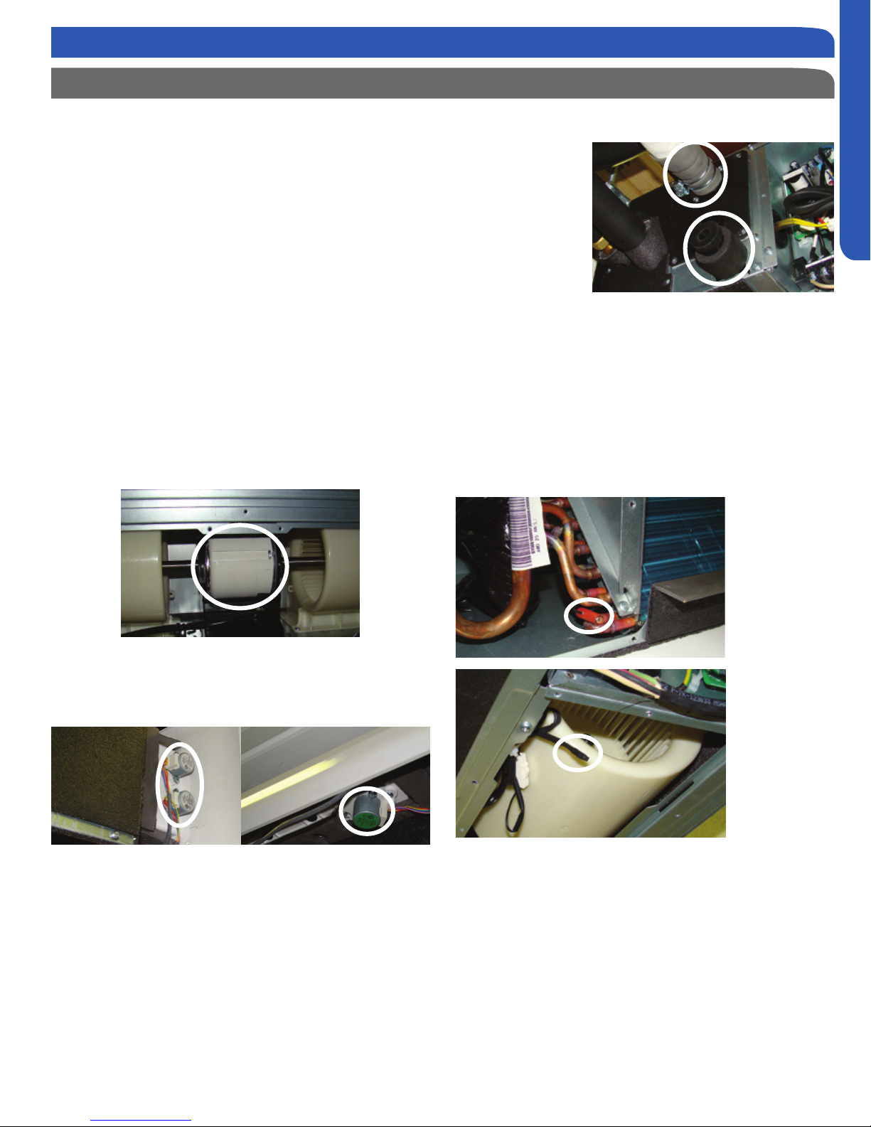
SLIM DUCT OVERVIEW
Slim Duct Components
Layout of Components
The layout of the system is very straightforward and
components are easily accessed should service be required.
• The circuit board is located under the electrical
control box cover.
• The blower motor and blower assemblies and room
air temperature sensor are accessed at the rear of
the unit.
• The evaporator coil and piping temperature sensor
are located under the top cover.
• The condensate pump and oat switch are accessed
under the removable panel next to the electrical
control box.
Power to operate the indoor unit comes from the electrical
line voltage terminal block at the outdoor unit. The wiring
includes 4 wires, 1, 2, 3 and ground. Wires 1 and 3 complete
the data path. These wires should always be 14 gauge
AWG Stranded type wire. Splices in wires 1 or 3 may cause
communication errors.
ENGLISH
Drain Ports
The indoor unit has
the option for either
gravity drain systems
or the use of an
internal condensate
pump with oat
switch. The pump is
capable of minimal
lift. If high lift is
required, the water
from the Slim Duct unit should be pumped to a eld supplied
condensate pump that is capable of high lift.
Temperature sensors located within the slim duct unit include
a pipe temperature sensor and a return air temperature
sensor. The pipe temperature sensor is used to sense the
temperature of the indoor coil in both cooling and heating
modes. The return air sensor sense the temperature of
the air being drawn into the wall mounted unit from the
conditioned space.
Fan/Blower Motor
The indoor unit features a multi speed blower motor that
will change speed to match the capacity demand from the
outdoor unit. The motor is a dual shaft type that powers two
individual blower assemblies.
Louver Motors
Separate motors located in the accessory supply air louver
control the operation of the motorized louvers. All of the
louver motors are controlled via commands received from the
remote control. The blower motor is controlled by both the
remote control and by commands from the outdoor unit ECU.
Refer to the Remote Control Information in the Reference
section for louver control/remote procedures.
Unlike typical air handlers found in the US market, these
units have metering devices located in the outdoor unit. The
metering devices are EEV type that are controlled by the
outdoor unit ECU.
Pipe
Sensor
Ambient Sensor
The wired controller can be congured to sense room air
temperature. The operating functions of these sensors is
explained in the Temperature Sensor Function section of this
manual.
All operating status and information is displayed on the wired
controller. The Slim Duct unit does not have a display.
There is no option for use with remote control.
When servicing a diagnostic error, ALWAYS refer to the
outdoor unit code to make diagnostic decisions.
TECHNICAL OVERVIEW
PAGE 53
Page 54

SLIM DUCT TECHNICAL OVERVIEW
Outdoor unit
Slim Duct Components
Indoor Unit Circuit Board
The indoor unit circuit board controls the switching functions
of the indoor unit. All control decisions are made by the
ENGLISH
outdoor unit ECU. The indoor board has some limited
diagnostic capability which will be covered in this manual.
5
6
air temperature sensing functions. All operational decisions
are controlled by the OUTDOOR UNIT ECU.
The connections on the indoor board are shown here in the
schematic drawing. Line voltage to power the indoor unit
comes in on Terminal Block connections 1 and 2. Power
connects from these terminal connections to CH- 1 and
CH-2 on the circuit board. If the board does not respond to
commands and has no display, check for line voltage at these
connections. When power is present at the indoor board, the
wired controller will be energized.
L Terminal
1
N Terminal
2
3
Communication Terminal
4
5A 250V Fuse
5
CN13 Sensors
6
CN18 Float Switch
Indoor unit
Indoor unit
11
7
8
9
10
11
12
7
CN1 Wired Remote
DIP Switches
CN14 Stepper Motor
CN15 Stepper Motor
CN6 Fan Motor
CN9 Condensate Pump
3wire 14AWG
Control Wiring
3wire 14AWG
Control Wiring
4
1
2
Power
Wiring
Power
Wiring
12
1
(
N
)
2
(L
)
3
(
C
)
1
(
N
)
2
(
L
)
3
(
C
)
Outdoor unit
1
(
N
)
2
(L
)
3
(
C
)
1
(
N
)
2
(
L
)
The control board has a replaceable 5A 250V fuse that
protects against excessive current. If power is present at
9
the board but the board does not work, check for continuity
through the fuse. Replace if the fuse is open.
8
10
The indoor unit temperature sensors are connected at
Plug CN-13. When testing the calibration of these sensors,
the wires can be released from the plug by pressing on the
tension tab on the side of the plug.
There 3 motors that control the directional movement of the
accessory louver. The motor connects to the circuit board at
3
Plug CN-14, CN-15 and CN-16. The motors are located in the
louver assembly.
The blower motor is connected to the circuit board at plug
CN-6.
The Slim Duct unit has a built in condensate pump. The pump
is connected to the circuit board on Plug CN-9. The pump is
energized whenever the Float Switch indicates that water
needs to be pumped from the cassette. The oat switch
connects onto the circuit board via Plug CN-18.
Built-in
Condensate
Pump and
Float Switch
The Indoor Unit Circuit Board communicates with the outdoor
unit ECU via a connection at Terminal Block screw 3. The
data pulse that sends the communication information can be
measured with a voltmeter placed to DCV range. From the
ground connection at the Terminal Block to the Number 3
screw connection, the voltage should pulse up and down when
data is being transmitted.
This control board has control over the fan louver movement,
manual fan blower control, indoor coil temperature and indoor
PAGE 54
TECHNICAL OVERVIEW
The oat switch and pump are located behind the removable
insulated cover next to the electrical control box. The pump
is hermetically sealed and requires no maintenance. The oat
switch is a normally closed switch, that opens as water rises.
The oat switch requires no maintenance.
The connection for the wired controller is made via Plug CN1
Page 55

SLIM DUCT TECHNICAL OVERVIEW
Slim Duct Components
SW1 DIP Switches
There are two sets of DIP switches on the Circuit Board. SW3
is for factory use only. SW1 is used to set the conguration
of the indoor unit operation. The rst three switches SW1-1,
SW1-2 and SW1-3 select the indoor unit capacity.
Air Delivery Power is set with DIP Switches SW1-4 and SW1-5.
The settings are shown in Hydrostatic Selection of 0Pa, up to
30Pa. SW1-7 and SW1-8 dene the unit type. The conversions
are as follows:
0Pa=0”w.c.
10Pa= .04”w.c.
20Pa=.08”w.c.
30Pa=.12”w.c.
• Recommended settings are for motorized Louver set
to 10Pa.
• Ducting limited to a total of .12”w.c. External Static
set to 30Pa.
ENGLISH
Accessory Louver Motors
The louver motors are stepper type motors that move the
louvers up/down. The motors are controlled by pulsed voltage
that cannot be measured. If the louver does not move when
it should, check for a bind in the louvers. If the louver is free to
move, refer to the Test Procedure Section.
Temperature Sensors
The Blower Assembly
The blower assembly
consists of 2 plastic
blowers. The blower
motor is a DC variable
speed dual shaft type.
A set screw holds each
blower wheel to the
blower motor.
The indoor blower
motor is a Multi Speed Fan Motor that is connected to the
indoor unit control board via Plug CN-6. The wiring from the
motor to indoor board consists of 5 wires connected to pins
that deliver line voltage, speed, and feedback information.
During normal operation, the indoor control board will
energize the indoor blower motor and request proper speed.
Fan power should be set using the DIP Switches SW1 settings.
temperature information to the ECU that may be used in
frequency adjustments. See Temperature Sensor Functions.
temperature control.
Both sensors are negative temperature coecient type that
reduce electrical resistance as temperature rises.
TECHNICAL OVERVIEW
The Piping Temperature
Sensor senses indoor coil
temperature in the cooling
mode and in the heating
mode. This sensor is used
for Anti Freezing and Anti
Cold Blow cycles. The
sensor also provides critical
The Ambient Temperature
Sensor senses room
temperature. This
sensor provides room
temperature information
to the ECU for calculation
of inverter capacity and
PAGE 55
Page 56

SLIM DUCT TESTING PROCEDURES
Test Condensate Pump and Associated Float Switch
If the internal condensate pump does not operate, the pump
may be bad or the oat switch may be defective. Perform the
following test:
ENGLISH
Float Switch and Condensate Pump
1. Access the electrical
control box.
2. Unplug the oat switch
from the circuit board.
Plug CN-18.
3. The pump should start.
4. If the pump does
not start, check
for voltage to the
pump at connector
CN-9. There should
be 230 Volts AC to
the pump. If there
is not, the circuit
board is defective. If there is proper voltage to
the pump, either the pump or associated pump wiring
is defective.
Testing Temperature Sensors Procedure
To test the electrical condition of a temperature sensor
perform the following:
1. Conrm the sensor is rmly attached to the circuit
board connection plug.
2. Remove the sensor wires from the connection plug
by releasing holding tension on the plugs tension tab.
3. Use an ohmmeter to test the electrical resistance of
the sensor.
Testing Temperature Sensors
The easiest problems to solve will involve codes that are
related to potential failure of temperature sensors. Common
problems may include loose connections, open electrically,
and out of calibration. Checking the condition of the sensors
requires a temperature probe and an ohmmeter.
The Reference
Section of this
manual contains
temperature
resistance
tables that
can be used
to check the
calibration of
the sensors.
The measured
resistance
must be within
the tolerances
printed on
the top of the
tables.
4. Measure the air temperature near the sensor
and compare the required resistance
against measured resistance. (refer to charts in
reference section) If the sensor is within calibration,
the sensor is good. If the sensor is out of calibration,
replace the sensor. (Tube Sensors should be removed
from socket and exposed to air temperature during
test.)
PAGE 56
TESTING
Page 57

SLIM DUCT TESTING PROCEDURES
Testing Communication Circuit
If an Error E7 occurs, perform the following test to determine
if the indoor control board is functioning properly to send data
to the outdoor unit.
Perform this test with the unit powered and all wiring
connected between indoor and outdoor unit.
Make sure all wiring between the indoor and outdoor unit
are correct. There should no splices between the indoor and
outdoor unit wiring connecting terminals 1 or 3. Make sure
wiring is correct, before performing this test.
1. Measure the DC voltage between terminals 1 and 3
on the indoor terminal block.
2. The voltage should uctuate between 8VDC
and 23VDC. The uctuating signal indicates a good
communication path.
3. If the voltage does not uctuate, and the wiring is
good, the indoor board is defective.
ENGLISH
TESTING
PAGE 57
Page 58

REMOTE CONTROLS
Wired Controller YR-E17
WIRED CONTROL PANEL FUNCTIONS
Features and Interface
ENGLISH
Clock; Parameter setting/Inquiry; Malfunction
display
Timer ON/OFF; Sleep function; Parameter
setting/Inquiry; Malfunction display
ROOM/SET temp. and humidity display, each
step is 0.5°C (1°F). For example, if the temp is
25°C (77°F), it will display 25.°C (77°F). Humidity
display function is reserved.
Energy Saving function. This icon will be displayed only when energy saving function is set.
Filter Cleaning
Child Lock
Lock/Central
Motion Sensing (Reserved)
Left/Right Swing. This icon is displayed only
when in swing function
Up/Down Swing. This icon is displayed only when
in swing function
User Friendly: Back light; Room temperature display
Sleep function. This icon is displayed when setting the
sleep function. Remaining sleeping time is displayed in
the top right corner.
Heat Reclaim Ventilation. This icon is displayed when
setting the heat reclaim ventilation.
Electrical Heating. This icon is displayed when electrical
heating is set on DC wired control.
Intelligent Mode--automatic cycling.
Cooling Mode
Heating Mode
Fan Mode
Dry Mode
Functions: Clock; Timer; Sleep Function; Heat Reclaim
Ventilation; ECO; Filter Cleaning; Error Code display; Child
Lock; Parameter Inquiry; Unit NO. Setting; Static Pressure
Grade Inquiry; Temp. Compensation setting; Forced
Cooling/Heating
PAGE 58
Page 59

WIRED CONTROLLER INSTALLATION
REMOTE CONTROLS
Wired Controller Wiring Instructions
Step By Step Guide To Slim Duct Unit Installation
There are three methods to connect the wired controller to
the indoor units.
A. One wired controller controls one indoor unit; the indoor
unit connects with the wired controller through a 3 conductor
shielded cable.
A
B. One wired controller can control up to 16 sets of indoor
units (max); A 3 conductor shielded cable must connect
the wired controller and the master unit (the indoor unit
connected to the wire controller directly). The others connect
to the master unit through a 2 conductor shielded cable.
B
ENGLISH
1. Put communication wire through the hole in the back cover
as shown.
2. Mount the back cover in the desired location, making sure
not to pinch the communication wire. Then connect the communication wire to CON1 port of the wired controller. Replace
the cover onto the unit to complete the installation.
C. Two wired controllers control one indoor unit. The wired
controller that connects with the indoor unit is called the
master controller, the other is called the slave controller. The
master wired controller and the indoor unit (as well as the
master controller and the slave controller) are all connected
through 3 conductor shielded cables.
Communication Wiring
Communication Wiring
Length
0~100 ft (0~30m) 22AWG(0.3mm2)x3-core
100~200 ft (30~60m) 20AWG(0.5mm2)x3-core
200~300 ft (0~90m) 18AWG(0.75mm2)x3-core
300-400 ft (90~120m) 16AWG(1.25mm2)x3-core
400~500 ft (120~150m) 14AWG(2mm2)x3-core
Dimension of Wiring
shielded wire
shielded wire
shielded wire
shielded wire
shielded wire
REMOTE CONTROLS
PAGE 59
Page 60
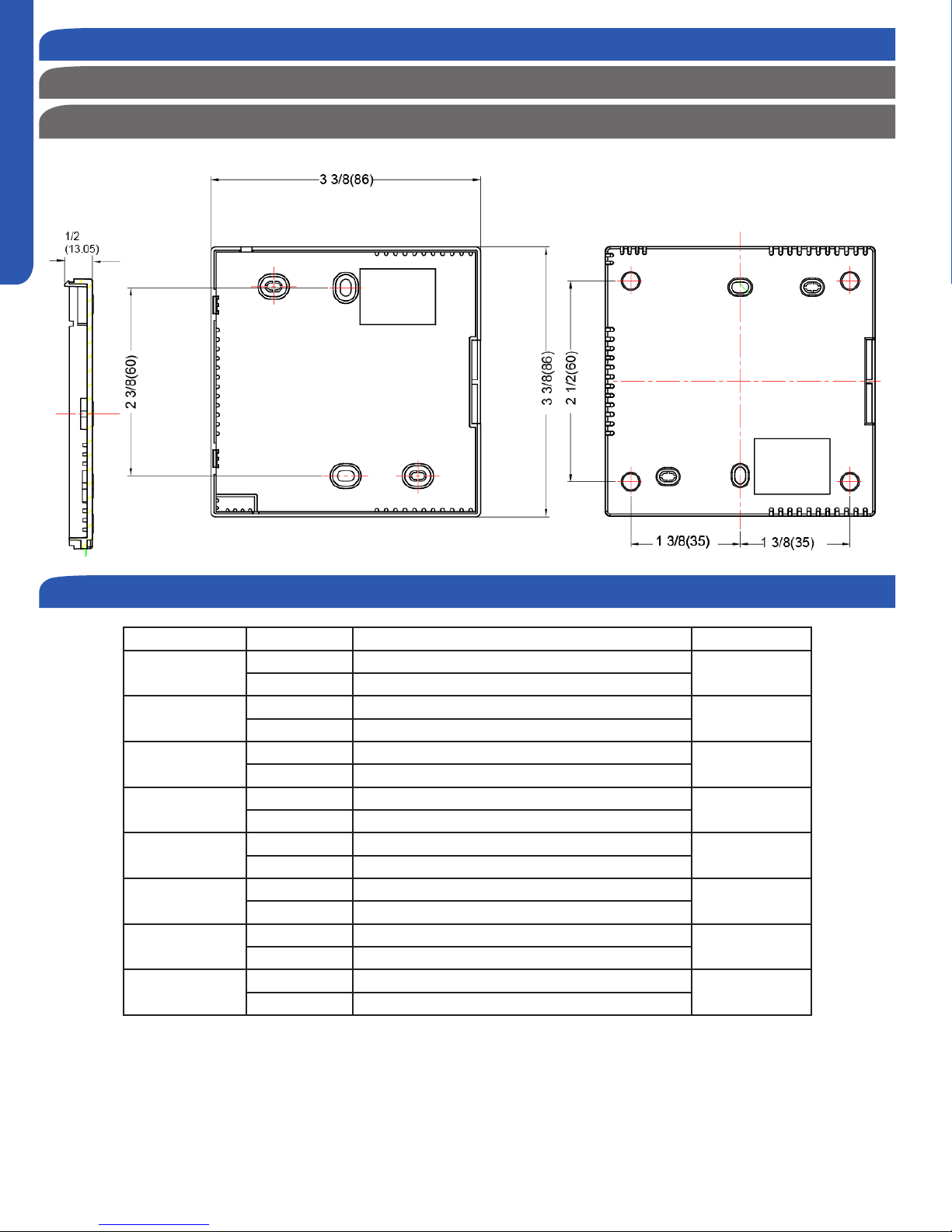
REMOTE CONTROLS
ENGLISH
WIRED CONTROLLER INSTALLATION
Wired Controller Wiring Instructions
Dimensions
Unit: inch (mm)
Dip Switch
Dip Switch ON/OFF Function Default Setting
SW1-1
SW1-2
SW1-3
SW1-4
SW1-5
SW1-6
SW1-7
SW1-8
ON Set as the slave controller
OFF Set as the master controller
ON Ambient temp. display available
OFF Ambient temp. display unavailable
ON Display ambient temp. from PCB of indoor
OFF Display ambient Temp. from wired controller
ON Auto-restart invalid
OFF Auto-restart valid
ON Fahrenheit
OFF Celsius
ON Swing angle adjustment available
OFF Swing angle adjustment unavailable
ON Up/Down and Left/Right swing
OFF Up/Down swing
ON Fresh Air unit
OFF General unit
OFF
OFF
OFF
OFF
OFF
OFF
OFF
OFF
PAGE 60
Page 61

WIRED CONTROLLER OPERATION
Settings & Functions
Initialization
The wired controller will
momentarily display
1
2
3
This cycle keeps repeating until initialization is complete.
The green ON/OFF LED will also ash continuously until
initialization is complete.
If the wired controller is unable to communicate with the
indoor unit PCB after powering on, initialization will terminate
in 4 minutes. The communication malfunction can be checked
using the malfunction inquiry function. (See Malfunction
Display)
all display icons upon
powering up or when
resetting the system.
During the initialization
process, the controller
will display, in a
repeating order:
88:88 (upper left
corner), 88:88 (upper
right corner) 88.8
(main temperature).
Mode Setting
NOTE: This function requires the ON/OFF key LED to be
turned OFF and the screen backlight to be illuminated.
Press and hold the MODE key for 5 seconds, the number of
the mode currently being used will display in the upper left
corner of the screen. (Default is 0) Press the pq keys to
change to one the dierent modes available: 0, 1, 2, or 3.
Press SET to conrm the setting.
NOTE: Corresponding modes
0 – [Intelligent] [Cooling] [Heating] [Fan] [Dry]
1 – [Cooling] [Heating] [Fan] [Dry]
2 – [Cooling] [Fan] [Dry]
3 – [Cooling] [Heating] [Fan] [Dry] (same as 1)
Error Code Display
Note: This function requires the ON/OFF key LED to be
turned OFF and the screen backlight to be illuminated.
Press and hold the TIME key for 10 seconds. The unit number
will display in the upper left corner of the screen. The error
code/historical error code will display in the upper right corner
of the screen. Press pq keys to select the unit number to
view its error codes. Under Error Code display screen, press
and hold the TIME key for 5 seconds to clear the fault codes of
all the units.
ENGLISH
Switching between Fahrenheit & Celsius
To switch from Celsius to Fahrenheit, select the mode you
wish to operate (COOL, HEAT, DRY, INTELLIGENT/AUTO).
Press and hold the p key to reach 30 °C then continue holding
the p key for 15 seconds until the display reads 86 °F. Use the
pq keys to adjust to desired temperature.
To switch from Fahrenheit to Celsius, select the mode you
wish to operate (COOL, HEAT, DRY, INTELLIGENT/AUTO).
Press and hold the q key to reach 60 °F then continue holding
the q key for 15 seconds until the display reads 16 °C. Use the
pq keys to adjust to desired temperature.
Clock Function
1. The clock is displayed in 24 Hour time
A. It cannot be set for AM/PM.
B. The clock function cannot be set when SLEEP
function or a timer function is currently set.
When the system is rst powered up, after initialization, the
clock will default to 12:00. Within 10 seconds of the clock being displayed, the time can be set. The clock icon and minutes
portion of the time display will be ashing. Press the pq keys
to adjust the minutes. (Pressing and holding the pq keys will
accelerate the time adjustment.) With the minutes set, press
the TIME key. The clock icon and hours portion of the time
display will now begin ashing. Press the pq keys to adjust
the hours. Press the SET key to conrm the setting.
To set the clock after initial power up or reset time has expired, press and hold the TIME key for 5 seconds. The clock
icon and minutes portion of the time display will begin ashing. Press the pq keys to adjust the minutes. With the minutes set, press the TIME key. The clock icon and hours portion
of the time display will now begin ashing. Press the pq keys
to adjust the hours. Press the SET key to conrm the setting.
If neither pq key is pressed within 10 seconds, or if the
MODE, FAN, or ON/OFF keys are pressed prior to pressing the
SET key, the setting function is canceled and the time reverts
back to the previous setting.
Screen Saving
With the system turned o, tap the TIME key to activate the
screen backlight (if not already lit).
1. Press and hold the TIME and q keys for 5 seconds to set the
backlight “on” time. The set time will be displayed in the upper
right corner of the screen.
2. Press the pq keys to adjust the time. Set times available
are: 0 seconds (backlight always on), 15 seconds, 30 seconds,
and 60 seconds. Initial default time is 15 seconds.
3. With time selection made, press the SET key to conrm the
setting.
Press the MODE, FAN, TIME, SET, or ON/OFF key to exit the
function. If no key is pressed in 10 seconds, the function
will also exit. If there are no current errors or historical error
codes, “--” will be displayed.
If neither pq key is pressed within 10 seconds, or if the
MODE, FAN, or ON/OFF keys are pressed prior to pressing the
SET key, the setting function is canceled and reverts back to
the previous setting.
REMOTE CONTROLS
PAGE 61
Page 62

REMOTE CONTROLS
WIRED CONTROLLER OPERATION
Settings & Functions
ECO Energy Saving Function
NOTE: This function requires the ON/OFF key LED to be
turned ON and the screen backlight to be illuminated.
ENGLISH
Press the SET key. The swing louver function icon will
ECO
be ashing) Press the SET key to conrm the setting. The ECO
icon will remain on.
To cancel ECO function, repeat the above steps.
NOTE: The energy saving default parameters are listed below:
74°F Lowest temperature limit of Cooling and Dry mode.
78°F Highest temperature limit of Heating mode.
74°F – 86°F Temperature adjustment range in Cooling and Dry
mode.
60°F – 78°F Temperature adjustment range in Heating mode.
be displayed. Press the pq keys to advance through
the functions to select ECO function. (The icon will
ECO Parameter Setting
NOTE: This function requires the ON/OFF key LED to be
turned ON and the screen backlight to be illuminated.
For Cooling
Under Cooling mode, set the temperature to 86°F. Press and
hold the FAN key for 5 seconds. The Cooling ECO parameter (ashing) will be displayed in the upper left corner of the
screen. Default temperature is 74°F. Press the pq keys to
adjust the lowest target cooling temperature. Press the SET
key to conrm the setting and exit setup.
For Heating
Under Heating mode, set the temperature to 60°F. Press and
hold the FAN key for 5 seconds. The Heating ECO parameter
(ashing) will be displayed in the upper right corner of the
screen. Default temperature is 78°F. Press the pq keys to
adjust the highest target heating temperature. Press the SET
key to conrm the setting and exit setup.
Timer Function Setting
NOTE: The display backlight must be illuminated before proceeding. To turn the backlight on, press any key (MODE, FAN, pq,
TIME, or SET) located at the bottom of the
display, or press the ON/OFF key located at
the top of the display.
Timer ON
Press the TIMER key once, the ON timer icon will appear in the
upper right corner of the screen. The ON icon and hour position are ashing. Press the pq keys to set the hour. Press
the TIMER key again, the ON icon and minutes position are
now ashing. Press the pq keys to set the minutes. Press the
SET key to conrm the setting.
Timer OFF
Press the TIMER key 3 times, the OFF timer icon will appear in
the upper right corner of the screen. The OFF icon and hour
position are ashing. Press the pq keys to set the hour.
Press the TIMER key again, the OFF icon and minutes position
are now ashing. Press the pq keys to set the minutes. Press
the SET key to conrm the setting.
Timer ON/OFF
Press the TIMER key 5 times, the ON/OFF timer icon will appear in the upper right corner of the screen. The ON icon and
hour position are ashing. Press the pq keys to set the hour.
Press the TIMER key again, the ON icon and minutes position
are now ashing. Press the pq keys to set the minutes. Press
the TIMER key again, the OFF icon and hour position are now
ashing. Press the pq keys to set the hour. Press the TIMER
key again, the OFF icon and minutes position are now ashing.
Press the pq keys to set the minutes. Press the SET key to
conrm the setting. Based on the times set, the indoor unit
will determine which event happens rst (ON-OFF or OFFON) and adjusts the arrow direction accordingly.
Static Pressure Grade Inquiry & Adjustment
NOTE: This function requires the ON/OFF key LED to be
turned ON and the screen backlight to be illuminated.
Press and hold the SET and FAN keys for 5 seconds. The current static pressure will be displayed in the upper right corner
of the screen and the “Static Pressure” icon will begin to ash.
Press the TIME key to shift the unit no. displayed in the upper
left corner of the screen. The unit numbers are from 00-15.
Press the pq keys to change the static pressure grade,
shown in the upper right corner of the screen.
Number range is 01-04. Press the SET key to conrm the
setting. Press the MODE, FAN, or ON/OFF key to exit the
function. If no key is pressed in 10 seconds, the function will
also exit.
PAGE 62
If neither pq key is pressed within 10 seconds, or if the
MODE, FAN, or ON/OFF keys are pressed prior to pressing the
SET key, the setting function is canceled and reverts back to
the previous setting.
Timer Cancel
Press the TIME key up to 9 times to cycle through the timer
settings. When the timer icon disappears, the timer function is
canceled.
Note: An active timer function will remain displayed on screen
until the set time has been reached and command completed.
Page 63

WIRED CONTROLLER OPERATION
Settings & Functions
Left/Right/Up/Down Swing
The swing function determines air circulation.
1. Press SET key to access
Swing function circulation.
2. Use pqkeys to select
desired swing function.
If SW7 is on, air will circulate
UP/DOWN/LEFT/RIGHT.
3. Press SET key to conrm
swing function selection.
Parameter Inquiry
NOTE: This function requires the screen backlight to be
illuminated. The ON/OFF key LED can be either On or O.
Press and hold the SET key for 5 seconds. The unit number
will be displayed in the upper left corner of the screen. The
data type and current data will be displayed in the upper right
corner of the screen.
Press the pq keys to scroll through the data types. (See
chart for data type/current data)
Press the MODE, FAN, SET, or ON/OFF key to exit the function. If no key is pressed in 10 seconds, the function will also
exit.
ENGLISH
Forced Cooling/Heating
Note: This function requires the ON/OFF key LED to be
turned OFF and the screen backlight to be illuminated.
Forced Cooling
When the system is turned o in cooling mode, press and hold
the ON/OFF key for 10 seconds. The system will enter forced
cooling. The temperature display will display a ashing “LL”.
Press the ON/OFF key to exit forced cooling mode.
Forced Heating
When the system is turned o in heating mode, press and hold
the ON/OFF key for 10 seconds. The system will enter forced
heating. The temperature display will display a ashing “HH”.
Press the ON/OFF key to exit forced heating mode.
NOTE: When in forced cooling or heating, all keys are disabled
except for the ON/OFF key.
Child Lock Function
NOTE: This function requires the screen backlight to be illuminated. The ON/OFF key LED can
be either On or O.
Child Lock can be used to prevent unintended
operation of the control unit.
1. Press SET and the q keys together for 5 seconds to
activate the Child Lock function. The child lock icon will be
displayed on the left side of the screen. All normal functions of
the keys will be disabled.
Unit Number Setting
NOTE: This function requires the screen backlight to be
illuminated. The ON/OFF key LED can be either On or O.
Press and hold the SET key for 10 seconds. The wired controller address and communication address between the indoor
and outdoor unit are displayed in the upper left corner of the
screen. The central address is displayed in the upper right
corner of the screen.
Press the pq keys to select the indoor unit number: 0 - 3F.
Press the SET key to conrm the setting. Press the MODE,
FAN, or ON/OFF key to exit the function. If no key is pressed in
10 seconds, the function will also exit.
2. To unlock the Child Lock function, press the SET key and
the q arrow together for 5 seconds. The child lock icon will
disappear from the screen. All normal functions of the keys
will be restored.
Temperature Compensation Setting
Note: This function requires the ON/OFF key LED to be
turned OFF and the screen backlight to be illuminated.
Press and hold the FAN keys for 5 seconds, the current
temperature compensation value is displayed in the upper
right corner of the screen. (The default value is 00). Press the
pq keys to change the temperature compensation value.
The adjustment range is -07°F to +07°F. Press the SET key to
conrm the setting. Press the MODE, FAN, TIME, or ON/OFF
key to exit the function. If no key is pressed in 10 seconds, the
function will also exit.
NOTE: The compensation value is used for ambient temperature and is valid only for the wired controller sensor.
REMOTE CONTROLS
PAGE 63
Page 64

REMOTE CONTROLS
WIRED CONTROLLER OPERATION
Settings & Functions
Sleep Function
NOTE: This function requires the ON/OFF key LED to be
turned ON and the screen backlight to be illuminated.
ENGLISH
Press the SET key. The swing louver function icon
will be displayed. Press the pq keys to advance
through the functions to select the SLEEP function. The Sleep and Sleep “o” time icons will be
displayed. (The Sleep icon will be ashing) Press the TIME key,
the “o” icon will begin to ash. Press the pq keys to set the
“o” time. (Time range is 0.5h to 72h) Press the SET key to
conrm the setting. The Sleep function and “o” time icons
will remain on.
If neither pq key is pressed within 10 seconds, or if the
MODE, FAN, or ON/OFF keys are pressed prior to pressing the
SET key, the setting function is canceled and reverts back to
the previous setting.
To cancel the Sleep function. Press the SET key. The swing
louver function icon will be displayed. Press the pq keys to
advance through the functions to select the SLEEP function.
The Sleep and Sleep “o” time icons will be displayed. (The
Sleep icon will be ashing) Press the SET key to cancel the
function.
Filter Cleaning
NOTE: This function requires the ON/OFF key LED to be
turned ON and the screen backlight to be illuminated.
Other Functions
Note: These functions require the ON/OFF key LED to be
turned OFF and the screen backlight to be illuminated.
Auto Restart
Setting DIP switch SW1-4 located on the PCB of the wired
control to the “on” position will disable the auto restart function. When the switch is in the “o” position, auto-restart
is enabled (default position). When the switch is in the “on”
position, auto-restart is disabled.
Information retained in auto-restart are: Mode, Fan Speed,
Temperature Setting, Swing State, and Heat Reclaim Ventila-
tion function.
Communication Error of Wired Controller
If there is no communication between the wired controller and
indoor unit for 4 minutes, when checking error codes, “07” will
be displayed in the upper right corner of the display.
The Filter Cleaning icon will start ashing when
the indoor unit has reached 500 hours of operating time.
After cleaning or replacing the lter, press the SET key to clear
the icon and reset the operating time.
Heat Reclaim Ventilation
NOTE: This function requires the ON/OFF key LED to be
turned ON and the screen backlight to be illuminated.
Press the SET key. The swing louver function icon
will be displayed. Press the pq keys to advance
through the functions to select the Heat Reclaim
Ventilation function. (The icon will be ashing)
Press the SET key to conrm the setting.
To cancel the Heat Reclaim Ventilation function, repeat the
above steps.
If neither pq key is pressed within 10 seconds, or if the
MODE, FAN, or ON/OFF keys are pressed prior to pressing the
SET key, the setting function is canceled and reverts back to
the previous setting.
This function is reserved for future models.
PAGE 64
Page 65

Display
Wireless Remote Controller
Note:
TURBO/QUIET modes are only available when the unit is under cooling or heating mode (not for auto or fan mode).
Running the unit in QUIET mode for a long period of time
may cause the room temperature to not reach the set
temperature. If this occurs, cancel QUIET mode and set the
fan speed to a higher setting.
3
COOL Button
In COOL mode, the unit operates in cooling. When FAN is
set to AUTO, the air conditioner automatically adjusts the
fan speed according to room temperature. The will be
displayed during COOL mode.
4
HEAT Button
In HEAT mode, warm air will blow out after a short period of
the time due to cold-air prevention function. When FAN is
set to AUTO, the air conditioner automatically adjusts the
fan speed according to room temperature. The will be
displayed during HEAT mode.
5
DRY Button
DRY mode is used to reduce humidity. In DRY mode, when
room temperature becomes lower than temp. setting +2°F,
unit will run intermittently at LOW speed regardless of FAN
setting. The will be displayed during DRY mode.
6
Temperature +/- Buttons
Temp + Every time the button is pressed, the temperature
setting increases.
Temp - Every time the button is pressed, temperature
setting decreases.
The operating temperature range is 60°F-86°F.
7
2
3
4
11
15
13
17
18
Functions
1
5
6
109
8
12
14
16
19
ENGLISH
1
Power Button
Press the ON/OFF button on the remote control to start
the unit.
2
TURBO/QUIET Button
The TURBO function is used for fast heating or cooling.
Press the TURBO/QUIET button once and the remote
control will display the TURBO icon on the bottom right
side of the remote display and switch the unit to the TURBO
function.
The QUIET function may be used when silence is needed for
fast rest or reading. Press the TURBO/QUIET button
again to switch to QUIET mode and the remote control will
display the QUIET
remote display.
Press the TURBO/QUIET button a third time to cancel
TURBO/QUIET and return to normal operation.
icon on the bottom left side of the
7
AUTO Button
Under the mode of auto operation, the air conditioner will
automatically select Cool, Heat, or Fan operation according
to set temperature. When FAN is set to AUTO the air conditioner automatically adjusts the fan speed according to room
temperature. The will be displayed during AUTO mode.
8
FAN Button
Fan speed selection
Press the FAN button. For each press, fan speed changes
as follows:
Remote control:
MED HI
LOW
The air conditioner fan will run according to the displayed fan
speed.
When FAN is set to AUTO, the air conditioner automatically
adjusts the fan speed according to room temperature.
REMOTE CONTROLS
circulated
AUTO
PAGE 65
Page 66

REMOTE CONTROLS
WIRELESS REMOTE CONTROLLER OPERATION
9
Louver SWING Button - Vertical
Air Flow Direction Adjustment
Press the SWING UP/DOWN button to choose the position of
the vertical airow louvers.
ENGLISH
Status display of air ow
COOL/DRY:
HEAT:
Caution:
• It is advisable not to keep the vertical louver in the down-
ward position for an extended period of time in COOL or
DRY mode, otherwise condensate water may form on the
louver.
•
Note:
When turning the unit on, the remote control will automatically
return the louver to the previous set swing position. When turn-
ing the unit o, the louver will rotate to the full open position
prior to closing.
10
Louver SWING Button - Horizontal
Press the SWING UP/DOWN button to choose the position of
the horizontal airow louvers.
4. Once the desired length of time is selected for the unit to
turn on, press the CONFIRM/CANCEL to conrm
this setting.
The remote control display changes as follows:
0.5h
TIMER ON TIMER OFF TIMER ON-OFF
0.5h 0.5h
0.5h
TIMER OFF-ON
BLANK
Cancel TIMER ON setting:
With a TIMER ON set, press the CONFIRM/CANCEL
button once to cancel the TIMER ON.
Turning the unit ON with the TIMER from it being OFF will look
like this on the remote control display:
Note:
Holding the TIMER ON button down will rapidly cycle
the time. After replacing batteries or a power failure occurs,
the time setting will need to be reset.
According to the Time setting sequence of TIMER ON or
TIMER OFF, either Start-Stop or Stop-Start can be achieved.
Status display of air ow
COOL/DRY/HEAT:
'
Caution:
• When humidity levels are high, condensate water may
occur at the air outlet if all horizontal louvers are adjusted
to left or right.
Note:
When turning the unit on, the remote control will automatically
return the louver to the previous set swing position. When turn-
ing the unit o, the louver will rotate to the full open position
prior to closing.
11
Timer ON Button
On-O Operation
1. Start the unit and select the desired operating mode.
2. Press the TIMER ON button to enter the TIMER ON
mode. The remote control will start ashing “ON”.
3. Every time the TIMER ON button is pressed the length of
time increases in 0.5 hour increments between hours 0 and
12, and 1 hour increments for times between hours 12 and
24.
12
Timer OFF Button
On-O Operation
1. Start the unit and select the desired operating mode.
2. Press the TIMER OFF button to enter the TIMER OFF
mode. The remote control will start ashing “OFF”.
3. Every time the TIMER OFF button is pressed the length of
time decreases in 0.5 hour increments between hours 0
and 12, and 1 hour increments for times between hours 12
and 24.
4. Once the desired length of time is selected for the unit to
turn o, press the CONFIRM/CANCEL to conrm
this setting.
The remote control display changes as follows:
0.5h
TIMER ON TIMER OFF TIMER ON-OFF
0.5h 0.5h
0.5h
TIMER OFF-ON
BLANK
Cancel TIMER OFF setting:
With a TIMER OFF set, press the CONFIRM/CANCEL
button once to cancel the TIMER OFF.
Turning the unit OFF with the TIMER from it being ON will look
like this on the remote control display:
Note:
Holding the TIMER OFF button down will rapidly cycle
PAGE 66
Page 67

Healthy
WIRELESS REMOTE CONTROLLER OPERATION
the time. After replacing batteries or a power failure occurs,
the time setting will need to be reset.
According to the Time setting sequence of TIMER ON or
TIMER OFF, either Start-Stop or Stop-Start can be achieved.
13
SLEEP Button
Sleep mode
Press the Extra Function button to enter additional
options, cycle the button to display the icon, the
icon will ash. Press the Conrm/Cancel button to
enter the sleep function.
Sleep Operation Mode
1. SLEEP mode during COOL, DRY modes
One hour after SLEEP mode starts, the temperature will
rise 2°F above set temperature, after another hour, the
temperature rises an additional 2°F. The unit will run for an
additional six hours, then turns o. The nal temperature
is 4°F higher than the initial set temperature. Using this
feature will help with achieving maximum eciency and
comfort from your unit while you sleep.
SLEEP operation starts SLEEP operation stops
1 hr
Temp.setting
Approx.6hrs
O
F
Rises 2
1 hr
O
Rises 2
F
In COOL, DRY mode
Unit stop
2. SLEEP mode during HEAT mode
One hour after SLEEP mode starts, the temperature will
decrease 4°F below set temperature, after another hour,
the temperature will decrease an additional 4°F. After an
additional three hours, the temperature will rise by 2°F.
The unit will run for an additional three hours, then turns
o. The nal temperature is 6°F lower than the initial set
temperature. Using this feature will help with achieving
maximum eciency and comfort from your unit while you
sleep.
Temp.setting
1 hr
SLEEP
operation starts
Decreases 4OF
1 hr
Decreases 4
3 hrs
In HEAT mode
O
F
3 hrs
Rises 3OF
SLEEP
operation stops
Unit stop
3. In AUTO mode
The unit operates in corresponding sleep mode adapted
to the automatically selected operation mode.
Note:
-When the unit is set to sleep mode, the fan speed will be
set to low speed and cannot be changed.
-When the TIMER function is set, the sleeping function
cannot be set. If the sleeping function has been set, and
the user sets the TIMER function, the sleeping function
will be canceled, and the unit will be set to the timer
function.
14
EXTRA FUNCTION Button
Function:
A) Refresh air - Feature not available on this series.
B) A-B Yard - This will allow you to control two separate units
with a single remote control.
Note: this feature would be setup at the time of installation
by the contractor.
C) Fan Mode - Is indicated by the
icon. Only the fan will
operate in this mode. See section 8 “FAN Button” for
changing the fan settings.
D) Intelligent upward airow, E) Intelligent downward airow,
F) Reset intelligent airow position
1. Press the ON/OFF button on the remote control to turn
the unit on.
Select the desired operating mode.
2. Setting the intelligent airow function
Press the EXTRA FUNCTION button to enter additional options. Press this button repeatedly to access
the louver settings. The louver icon will cycle through the
following three settings.
airflow
upward
Healthy
airflow
downward
Present
position
Select the desired position, then press the CONFIRM/
CANCEL button to set the function.
3. Canceling the intelligent airow function
Press the EXTRA FUNCTION button to enter additional options. Press this button repeatedly to access the
louver settings. Cycle the button to the louver icon “present” position, then press the CONFIRM/CANCEL
button to cancel the function.
Notice: Do not reposition the horizontal louver by hand.
This may cause the louver to run incorrectly and not
match the icon displayed on the remote control. If the
louver is not running correctly, turn the unit o for one
minute, then back on, and adjust the louver setting with
the remote control.
Note:
1. After setting the intelligent airow function, the louver
position is xed.
2. In cooling, it is better to select the mode.
3. In heating, it is better to select the mode.
4. In cooling and dry modes, using the air conditioner for a
long period of time under high humidity conditions, condensate water may form on the grille/louver.
ENGLISH
REMOTE CONTROLS
PAGE 67
Page 68

REMOTE CONTROLS
WIRELESS REMOTE CONTROLLER OPERATION
G) Fahrenheit/Celsius mode shift on unit and remote -
To switch between Fahrenheit and Celsius press the EXTRA
FUNCTION button until either Celsius or Fahrenheit
is displayed. Press the CONFIRM/CANCEL button to
apply the change.
ENGLISH
H) 50°F low temperature heating - Feature not available on
this series.
I) Electrical heating - Feature not available on this series.
15
HEALTH Button
Feature not available on this series.
16
Conrm/Cancel Button
Function: Setting and canceling timer and other functions.
17
LOCK Button
Used to lock buttons and LCD display
18
LIGHT Button
Turns indoor unit display on and o
19
RESET Button
If the remote control is not functioning properly, use a pen
point or similar object to depress this button to reset the
remote.
PAGE 68
Page 69

REFERENCES
Timer lamp
flash time
Running lamp
flash time
1 Faulty of outdoor uni t EEPROM 15 2 1
F12
2 I PM overcurrent or short circuit 16 2 2
F1
4 Communication fai lure between Module and ECU 18 2 4
F3
5 Module operated overload 19 2 5
F20
6 Module low or high voltage 1A 2 6
F19
8
Discharging temperature overheating.Lack of
refrigerant,
ambient temperature too high or PMVs blocked.
1C 2 8 F4
9 Malfunction of the DC fan motor 1D 2 9
F8
10 Malfunction of de frosting temp. sensor 1E 3 0
F21
11 Malfunction of compressor suction temp. sensor 1F 3 1
F7
12 Malfunction of ambie nt temp. sensor 20 3 2
F6
13
Malfunction of compressor discharge temp.
sensor
21 3 3
F25
15
Communication failure between indoor&outdoor
unit
23 3 5
E7
16 Lack of refrigerant or discharging 24 3 6
F13
17 4-way valve switching failure 25 3 7
F14
18 Loss of synchronism detection 26 3 8
F11
20 Indoor thermal overload 28 4 0
E9
21 Indoor frosted 29 4 1
E5
23 Module thermal overload 2B 4 3
F5
24 Compressor start failure 2C 4 4
F2
25 Module input overcurrent 2D 4 5
F23
26 MCU reset 2E 4 6
F9
27 Module current detect circuit malfunction 2F 4 7
F24
28
Malfunction of liquid pipe temp. sensor for
indoor unit A
30 4 8 F 10
29
Malfunction of liquid pipe temp. sensor for
indoor unit B
31 4 9 F 16
30
Malfunction of liquid pipe temp. sensor for
indoor unit C
32 5 0
F17
31
Malfunction of liquid pipe temp. sensor for
indoor unit D
33 5 1
F18
32
Malfunction of gas pipe temp. sensor for indoor
unit A
34 5 2 F 29
33
Malfunction of gas pipe temp. sensor for indoor
unit B
35 5 3 F 30
34
Malfunction of gas pipe temp. sensor for indoor
unit C
36 5 4 F 31
35
Malfunction of gas pipe temp. sensor for indoor
unit D
37 5 5 F 32
36
Malfunction of gas pipe temp. sensor for indoor
unit E
38 5 6
F26
38
Malfunction of module temp.sensor
Momentary power failure detection
3A 5 8
F35
39 Malfunction of condensi ng temp. sensor 3B 5 9
F36
40
Malfunction of liquid pipe temp. sensor for
indoor unit E
3C 6 0 F33
41 Malfunction of ‘Toci’temp. sensor 3D 6 1 F38
42 System high pressure switch off 3E 6 2 F39
43 System low pressure switch off 3F 6 3 F40
44
System high pressure protection.Refrigerant
overabundance,
High condensing temp. or malfunction of fan
motor.
40 6 4 F41
45
System low pressure protection.Refrigerant
shortage,
Low defrosting temp., or malfunction of fan
motor.
41 6 5 F42
Trouble shooting
Outdoor
LED
display
Outdoor unit fault possible reasons
Wired controller
display(Hex)---for
duct
Cassette indoor display outdoor
Wall mounted
indoor display
Troubleshooting
ENGLISH
REFERENCES
PAGE 69
Page 70

ENGLISH
Yellow Blue Whi te B lack R ed
Yellow Infinity Ω 345K Ω 238K Ω Infinity Ω
Blue 4.7K Ω 4.54M Ω Infinity Ω
Whit e 107K Ω
Infinity Ω
Bl ack Infinity Ω
Red
Wall Mount F an Motor Res istanc e Value s
Blue Vi olet Yellow O range R ed
Blue 383 Ω 388 Ω
390 Ω 195 Ω
Viol et 381 Ω 385 Ω 189 Ω
Yellow 388 Ω 193 Ω
Oran ge 196 Ω
Red
Wall Mount Vertical Louver Motor Resistance Values
Red B lack Wh ite Yellow Blue
Red Infinity Ω Infinity Ω Infi nity Ω Infinity Ω
Bl ack
1.23K Ω
211.5K Ω 4.75M Ω
Whit e 212.7K Ω 4.75M Ω
Yellow 5.05M Ω
Blue
Ducted Fan Motor Resistance Values
Blue Vi olet Yellow O range R ed
Blue 298 Ω 297 Ω 297 Ω 149 Ω
Viol et
299 Ω
299 Ω 151 Ω
Yellow 298 Ω 149 Ω
Oran ge 150 Ω
Red
Ducte d Horiz ontal Lou ver Motor R esist ance Valu es
Blue Vi olet Yellow O range R ed
Blue 590 Ω 596 Ω 591 Ω 297 Ω
Viol et
593 Ω
588 Ω 294 Ω
Yellow 595 Ω 300 Ω
Oran ge 295 Ω
Red
Ducted Ver tical Louver Motor Resistance Values
Oran ge Yellow Blue Vi olet Red
Oran ge 398 Ω 398 Ω 399 Ω 200 Ω
Yellow
396 Ω
397 Ω 198 Ω
Blue 399 Ω 199 Ω
Viol et 200 Ω
Red
Cassette Louv er Motor Resistance Values
Red B lack Wh ite Yellow Blue
Red Infinity Ω Infinity Ω Infi nity Ω Infinity Ω
Bl ack
1.23K Ω
211.5K Ω 4.75M Ω
Whit e 212.7K Ω 4.75M Ω
Yellow 5.05M Ω
Blue
Outd oor Uni t Fan Mot or Re sistan ce Value s
Blue Vi olet Yellow O range R ed
Blue 47 Ω
46 Ω
46 Ω 46 Ω
Viol et 92 Ω 92 Ω 92 Ω
Yellow 91 Ω 91 Ω
Oran ge 91 Ω
Red
EEV Stepper Motor Resistance Values
Blue Vi olet Yellow O range R ed
Blue 393 Ω
394 Ω
395 Ω 196 Ω
Viol et 396 Ω 397 Ω 198 Ω
Yellow 398 Ω 199 Ω
Oran ge 200 Ω
Red
Wall Mount Hor izontal Louv er Motor Resi stance Values
Oran ge Or ange Red Br own Yellow Blue
Oran ge 758 Ω 758 Ω 159 Ω 189 Ω
233 Ω
Oran ge 0 Ω 600 Ω 570 Ω 526 Ω
Red 600 Ω 570 Ω 526 Ω
Br own 31 Ω 75 Ω
Yellow 45 Ω
Blue
Cassette Fan Motor Resistance Val ues
REFERENCES
Resistance Values for Wall Mounted, Ducted, and Cassette Units
PAGE 70
REFERENCES
Page 71

REFERENCES
Error Detection
The LED ashes when any of the following errors are detected:
1. When a protection device of the indoor or the outdoor unit activated or when the thermistor malfunctions, disabling
equipment operation
2. When a signal transmission error occurs between the indoor and outdoor units. In either case. conduct the appropriate
diagnostic procedures.
ENGLISH
REFERENCES
PAGE 71
Page 72

Problem
ENGLISH
REFERENCES
Problems & Solutions
Piping Length Limits
Length Limits
PAGE 72
REFERENCES
Page 73

REFERENCES
Component Ratings
ENGLISH
REFERENCES
PAGE 73
Page 74

REFERENCES
Duct work Installation
Roof Installation
ENGLISH
Ceiling
Air supply
Indoor unit
Roof
Unit
Return air
Soft
connection
or static
box
Duct Work Installation
Air outlet grill
Air supply
Return air box
Transition
duct
Rounded
duct
Return air box
Unit
Return air
Tie-in of air
Air return blind
distribution
Air distribution
Air return duct
Indoor unit
Rivet
Use rivet to connect the air return duct on the air return inlet of the indoor unit,
then connect the other end with the air return.
PAGE 74
REFERENCES
Page 75

REFERENCES
Wiring
Cover plate of the outdoor unit to expose the terminal block
connections.
Line Voltage from Circuit Breaker/Disconnect to outdoor unit
wire terminal
Always follow local and national codes when installing
electrical wiring. The required fuse size can be found in the
product specication section of this manual.
Connect wiring from indoor units
Use 14/4 AWG Stranded wire when connecting the outdoor
unit to the indoor unit. Connect the wiring to the correct
terminals based upon the piping connections. For example,
Circuit A wiring goes to the piping feeding Circuit A. Do not
cross the wiring and piping.
ENGLISH
Line Voltage
Terminals
Indoor Unit Terminals
Electrical Connections Indoor and Outdoor Units
14 AWG Stranded Wire Only. (Central Controller Not
Used)
Maintain 10 feet of separation between TV and any Radio
wiring.
REFERENCES
PAGE 75
Page 76

ENGLISH
REFERENCES
Wiring
PAGE 76
REFERENCES
Page 77

REFERENCES
Wiring
ENGLISH
REFERENCES
PAGE 77
Page 78

ENGLISH
REFERENCES
Wiring
PAGE 78
REFERENCES
Page 79

REFERENCES
Wiring
ENGLISH
REFERENCES
PAGE 79
Page 80

ENGLISH
REFERENCES
Wiring
PAGE 80
REFERENCES
Page 81

REFERENCES
2U
Wiring
ENGLISH
REFERENCES
PAGE 81
Page 82

ENGLISH
REFERENCES
Wiring
CN20 Connector for room card
PAGE 82
REFERENCES
Page 83

REFERENCES
Wiring
ENGLISH
SWI
REFERENCES
PAGE 83
Page 84

ENGLISH
REFERENCES
Wiring
PAGE 84
REFERENCES
Page 85

REFERENCES
CN11
CN9
CN10
Wiring
PCB(1)
CN36
ENGLISH
CN3
CN2
CN1
CN15
CN16
CN17
CN18
CN19
CN20
CN21
CN22
CN23
REFERENCES
CN24
CN25
CN28
PAGE 85
Page 86

ENGLISH
REFERENCES
CIRCUIT DIAGRAMS
PAGE 86
REFERENCES
Page 87

REFERENCES
CIRCUIT DIAGRAMS
ENGLISH
REFERENCES
PAGE 87
Page 88

ENGLISH
REFERENCES
WIRING DIAGRAMS
PAGE 88
REFERENCES
Page 89

REFERENCES
WIRING DIAGRAMS
ENGLISH
REFERENCES
PAGE 89
Page 90

ENGLISH
REFERENCES
2U - Piping Installation Dimensions
PAGE 90
REFERENCES
Page 91

REFERENCES
2U - Piping Installation Dimensions
ENGLISH
In case elevation B is more than 16 feet, the oil trap should be installed every 16 to 23 feet.
In case the total pipe length (B1+B2) is more than 66 feet, the refrigerant should be charged according to 66 g/ft
(20g/m)
REFERENCES
PAGE 91
Page 92

ENGLISH
REFERENCES
Refrigerant Diagram
PAGE 92
REFERENCES
Page 93

REFERENCES
Refrigerant Diagram
ENGLISH
REFERENCES
PAGE 93
Page 94

ENGLISH
REFERENCES
3U - Piping Installation Dimensions
PAGE 94
REFERENCES
Page 95

REFERENCES
4U - Piping Installation Dimensions
ENGLISH
REFERENCES
PAGE 95
Page 96

FLOW CHARTS
ENGLISH
ashes
ashes
ashes
ashes
When the thermistor input is more than4.92V or less than 0.08V during compressor operation
Caution: Be sure to turn power o before connecting or disconnecting the connector, or parts
may sustain damage.
Check the connector connection
Check the connector connection
NO
Is it normal?
YES
Thermistor resistance check
NO
Is it normal?
YES
Replace the indoor unit PCB
Thermistor resistance check method:
Remove the connector of the thermistor from the PCB and measure the resistance of the thermistor using an
ohmmeter. The relationship between normal temperature and resistance is shownin the indoor thermistor
chart located in the reference section.
Correct the connection
Replace the thermistor
PAGE 96
REFERENCES
Page 97

FLOW CHARTS
Indoor EEPROM error
Outdoor EEPROM error; Outdoor LED ashes 1 time
When the data of the EEPROM is in error or the EEPROM is damaged
Caution: Be sure to turn power switch o before connecting or disconnecting the connector, or parts
may sustain damage.
ENGLISH
Replace the indoor or outdoor main board
REFERENCES
PAGE 97
Page 98

ENGLISH
How to Check the Fan Motor (DC)
FLOW CHARTS
When the detection rotation signal is not received in 2 minutes
Operation halts due to broken connections inside the fan motor
Fan motor overheat protection
Operation halts due to broken fan motor lead wires
Detection error due to faulty indoor unit PCB
Caution: Be sure to turn power switch o before connecting or disconnecting the connector, or
parts may sustain damage.
Note: When the a/c is charging do not remove or insert plugs in order to avoid damage to the motor
When the unit is operating, do not remove or insert plugs in order to avoid damage to the motor.
PAGE 98
REFERENCES
Page 99

Turn o the power supply and rotate
the fan by hand
Does fan rotate smoothly?
YES
Turn power on and operate fan
Does it run?
FLOW CHARTS
ENGLISH
NO
Replace fan motor
NO
Check output of fan motor connector
YES
Is motor power voltage DC310V
Is the feedback command pulse
generated?
Is motor control power DC15V
YES
NO
Replace indoor fan motor PCB Is feedback command voltage
1-6VDC generated?
YES
generated?
YES
generated?
YES
NO
Replace indoor unit PCB
NO
Replace indoor unit PCB
NO
Replace fan motor
YES
REFERENCES
Replace fan motor
Replace indoor unit PCB
PAGE 99
Page 100

LED 1 ashes 9 times
FLOW CHARTS
ENGLISH
DC fan motor error is detected by checking the fan running condition
When the data of the EEPROM is in error or the EEPROM is damaged
DC fan motor protection due to a fault in the DC fan motor
• DCfan motor protection due to the DC fan motor fault
• DC fan motor protection due to faulty PCB
Caution: Be sure to turn power switch o before connecting or disconnecting the
Caution: Be sure to turn power switch o before connecting or disconnecting the connector,
connector, or parts may sustain damage.
or parts may sustain damage.
Check to see that the terminal on the
outdoor main board is properly inserted.
NO
Is it normal?
YES
Reinsert the terminals.
Using the remote control, turn on
the unit in Cool Mode and check to
see if the motor is running.
YES
Measure the voltage between
terminals 3 and 6 of the connector,
about 0-5VDC
Is it normal?
NO
The motor of the outdoor unit is
damaged and needs to be replaced.
NO
Measure the voltage between terminals
1 and 3 of the fan motor connector on the
main board about 310VDC. Measure the
voltage between terminals 3 and 4 of the
connector about 15VDC. Measure the
voltage between terminals 5 and 3 of the
connector about 1-6VDC.
YES
Is it normal?
NO
The main board of the outdoor
unit is damaged and needs to be
replaced.
PAGE 100
REFERENCES
 Loading...