


TRM8
MONITORING SYS
Installation & Operation
®
®
trans
nova
DESIGNED AND
ASSEMBLED IN THE
USA
MONITORING SYSTEM
Declaration of Conformity
Application of Council Directive: 73/23/EEC (low voltage directive)
Standard(s) to which Conformity is Declared: EN55013
EN55020
EN60065
Manufacturer’s Name: Hafler
Manufacturer’s Address: 546 South Rockford Drive, Tempe, Arizona 85281
Importer’s Name: _______________________________________________________
Importer’s Address: _______________________________________________________
Type of Equipment:
Model No.: TRM8
Serial No. ______________________________Year of Mfg. ’96 ’97 ’98
2-channel Audio Power Amplifier/Speaker
I, the undersigned, hereby declare that the equipment specified above conforms
to the above Directive(s) and Standard(s)
Place: Hafler
Date: James C. Strickland, VP Engineering
12/11/96

NOTICE - IMPORTANT SAFETY INFORMATION
The lightning flash with arrowhead symbol within an equilateral triangle
is intended to alert the user to the presence of uninsulated "dangerous
CAUTION
RISK OF ELECTRIC SHOCK
DO NOT OPEN
WARNING:
DO NOT EXPOSE THIS EQUIPMENT TO RAIN OR MOISTURE.
TO PREVENT FIRE OR SHOCK HAZARD
!
voltage" within the product's enclosure, that may be of sufficient magnitude to constitute a risk of electric shock to persons.
The exclamation point within an equilateral triangle is intended to alert
the user of the presence of important operating and maintenance
(servicing) instructions in the literature accompanying the appliance.
1. READ INSTRUCTIONS
All the safety and operating instructions of your Hafler equipment
should be read before power is applied to the equipment.
2. RETAIN OWNER'S MANUAL
These safety and operating instructions should be retained for
future reference.
3. HEED WARNINGS
All warnings on the equipment and in the operating instructions are
important and should be followed.
4. FOLLOW INSTRUCTIONS
All operating and use instructions are important and should be
followed.
5. HEAT
The equipment should be kept away from areas of high temperature, i.e., heater vents, radiators, stoves/ovens, fireplaces, etc.
6. VENTILATION
The equipment should be used in an area suitable for proper
ventilation. Care should be taken not to impede airflow in and
around the cabinet.
7. WATER AND MOISTURE
The equipment should not be used in or around water, such as a
bathtub, sink, or swimming area. Also, the equipment should not
be used in areas prone to flooding, such as a basement.
8. POWER SOURCES
The equipment should be connected only to a power source of the
same voltage and frequency as that listed on the rear panel above
the power cord entry point.
9. POWER CORD PROTECTION
Power cords should be arranged so they do not interfere with the
movement of objects in the room: people, fan blades, utility carts,
etc. Also, care should be taken that the cord is not pinched or cut,
and placed so it is not in danger of being pinched or cut, as in under
a rug, around a tight corner, etc.
connection. It is important that the blades of the equipment’s plug
be able to fully insert into the mating receptacle. Never remove the
round grounding pin on the plug in an attempt to mate to a two
wire ungrounded receptacle: use a grounding adaptor with the
grounding tab or wire suitably connected to earth ground.
11. NON-USE PERIODS
During periods of extended non-use, the power cord should be
unplugged from the power source.
12. CLEANING
The equipment should be cleaned only as detailed in the operating
instructions.
13. OBJECT AND LIQUID ENTRY
Care should be taken so that objects and/or liquids, such as cleaning
fluids or beverages, are not spilled into the enclosure of the
equipment.
14. DAMAGE REQUIRING SERVICE
Hafler equipment should be serviced by qualified service personnel
when:
A. The power supply cord or plug has been damaged, or
B. Objects have fallen onto, or liquid has been spilled into the
equipment, or
C. The equipment has been exposed to rain, or
D. The equipment does not appear to operate normally or
exhibits a marked change in performance, or
E. The equipment has been dropped, or the enclosure has
been damaged.
15. SERVICING
The user should not attempt to service the equipment beyond that
which is described in the operating instructions. All other service
should be referred to qualified service personnel.
10. POWER CORD GROUNDING
The power supply cord is of a three wire grounded type, designed
to reduce the risk of electric shock sustained from a live cabinet. It
is assumed to be of suitable length for most uses of the equipment.
The use of extension cords and power strips is discouraged unless
they are of suitable rating to deliver the required total current for
safe operation of all connected equipment. Furthermore, extension
cords or power strips must provide the same three wire grounded
16. CARTS AND STANDS
The equipment should be used with carts or stands only of sufficient
strength and stability for the use intended.
An equipment and cart combination should be moved with care.
Quick stops and starts, excessive force, and uneven surfaces may
cause the equipment and cart combination to topple.
– i –

ADVERTENCIA – INFORMACION DE SEGURIDAD IMPORTANTE
El símbolo de flecha relámpago dentro de un triángulo equilátero, es para
alertar al usario de la presencia de “voltajes peligrosos” no aislados en el
interior del aparato, los cuales pueden ser de suficiente magnitud para
constituir un riesgo de choque eléctrico a las personas.
El símbolo de exclamación dentro de un triángulo equilátero, es para alertar
al usuario de la presencia de instrucciones importantes de operación y
mantenimiento (servicio) en la documentación que acompaña al equipo.
SPAÑOL
E
PELIGRO
RIESGO DE DESCARGA
ELÉCTRICA NO ABRÍR.
PRECAUCÍON:
Para Prevenir el incendio o la descarga electrica, no
exponer este equipo a la lluvia o a la humedad.
!
1. LEA LAS INSTRUCCIONES
Todas las instrucciones de seguidad y operación de su equipo
Hafler, deben ser leídas antes de que el equipo sea conectado
dléctricamente.
2. CONSERVE EL MANUAL DEL PROPIETARIO
Estas instrucciones de seguridad y operación, deben ser conservadas
para futuras referencias.
3. CUADROS DE ADVERTENCIAS
Todas las advertencias en el equipo y en las instrucciones de
operación, son importantes y deben ser seguidas.
4. SIGA LAS INSTRUCCIONES
Todas las instrucciones de uso y operación son importantes y deben
ser seguidas.
5. CALOR
El equipo debe ser mantenido lejos de areas de alta temperatura,
como por ejemplo: ventilaciones de calentadores, radiadores,
estufas/hornos, hogueras, etc.
6. VENTILACION
El equip debe ser usado en áreas con ventilación adecuada. Deben
er tornadas las precauciones necesarias para no impedir el flujo de
aire dentro y alrededor del aparato.
poder suministrar la corrioente requerida pra la operación segura
de todo el equipo conectado. Aun más, las extensiones deben
proveer de la misma conección aterrada de tres hiles. Es importante
que el enchufe se pueda introducir completamente en el receptáculo.
Nunca remeva el pin de aterramiento en un intento por conectar el
cable en un receptáculo de dos hilos no aterrado: use un adaptador
de aterramiento que esté adecuadamente conectado a un punto de
tierra.
11. PERIODOS SIN USO
Durante períodos prolongados sin uso del equipo, el cable de
corriente debe ser desconectado de la fuente de electrixidad.
12. LIMPIEZA
El equip debe ser limpiado solo en la forma que se detalla en las
instrucciones de operación.
13. INTRODUCCIÓN DE OBJETOS Y LIQUIDO
Deben ser tornadas precauciones con el fin de que objetos y/ó
líquidos, tales como fluidos de limpieza y gaseosas, no sean
derramados dentro del chassis del aparato.
14. DAÑOS QUE REQUIEREN DE SERVICIO
Los equipos Hafler deben ser llevados a servicio por personal
calificado cuando:
7. AGUA Y HUMEDAD
El equipo no debe ser usado en el agua ó alrededor de ésta, tales
como en una bañera, tanque o áreas de nado. También, el equipo
no debe ser usado en áreas propensas a inundaciones, tales como
en un sótano.
8. FUENTES DE PODER
El equipo debe ser conectado a una fuente de poder del mismo
voltaje y frecuencia que el indicado en el panel trasero sobre el
punto de entrada del cable de corriente.
9. PROTECCION DEL CABLE DE CORRIENTE
Los cables de corriente deben ser dispuestos de forma tal que no
interfieran con el movimiento de objetos en la sala: personas, aspas
de ventilación, carretillas, etc. También, es necesario tener cuidado
de que el cable no esté punzado o cortado, y debe estar ubicado de
forma tal que esto no ocurra, como podría suceder debajo de una
alfombra o al pasar el cable por una esquina aguda, etc.
10. ATERRAMIENTO DEL CABLE DE CORRIENTE
El cable de corriente es del tipo aterrado de tres hilos, diseñado para
reducir el riesgo de una descarga eléctrica procendent de un chasis
energizado. Se asume que su longitud es suficiente para la mayoría
de usos del equipo. El uso de extensiones y multienchufes no es
recomendado, a menos que tengan el amperaje adecuado para
A. El cable de corriente ó el enchufe haya sido dañado, ó
B. Objetos ó líquido hayan sido introducidos ó derramado en
el equipo, ó
C. El equipo haya sido expuesto a lluvia, ó
D. El equipo aparenta no operar normalmente ó exhibe un
marcado cambio en su desempeño, ó
E. El equipo se ha caído, o el chassis ha sido golpeado.
15. SERVICIO
El usuario no deberá intentar darle servicio al equipo más allá de lo
que está descrito en el instructivo de operación. Todo lo demás,
deberá ser referido a servicio por personal calificado.
16. CARRETILLAS Y SOPORTES
El equipo podrá ser usado con carretillas y soportes que tengan la
fortaleza y estabilidad suficiente para el uso previsto.
La combinación equipo/carretilla deberá ser movida con cuidado.
Rápidas paradas y arranques, excesiva fuerza y superficies imparejas,
pueden causar el volcamiento del conjunto de carretilla/equipo.
– ii –

ATTENTION: INFORMATIONS IMPORTANTES DE SÉCURITÉ
La lumière clignotante du symbole de la flêche à l'intérieur d'un triangle
équilatéral, à pour objet d'alerter l'utilisateur de la présence “d'un voltage
dangereux” non-isolé à l'intérieur du produit, qui pourrait être de magnitude
suffisante au risque d'éléctrocution.
RANÇAIS
F
ATTENTION
RISQUE DE CHOC
ÉLECTRIQUE NE PAS OUVRIR
!
AVERTISSEMENT:
Afin de prévenir les risques de feu ou de choc, ne pas
exposer cet appareil à la pluie ou à l'humidité.
1. LIRE LES INSTRUCTIONS
Le mode d'emploi et les mesures de sécurité de votre équipement
Hafler devraient être consultés avant sa mise en marche.
2. CONSERVER LE GUIDE DE L'UTILISATEUR
Le mode e'emploi et les mesures de sécurité devraient être
conservés pour des références futures.
3. CONSIDÉRATIONS DE MISE EN GARDE
Le mode d'emploi et les mises en garde concernant cet équipement
sont de grande importance et devraient être suivis.
4. SUIVRE LE MODE E'EMPLOI
Le mode d'emploi et les conseils d'utilisation sont importants et
devraient être suivis.
5. CHALEUR
Le matériel devrait être préservé loin de toute source de chaleur:
radiateurs, cuisinière/fours, cheminées,…etc.
6. VENTILATION
Le matériel devrait être utilisé dans un endroit à bonne ventilation. Il reste nécessaire de respecter la circulation de flux d'air à
l'intérier et autour du meuble.
Le point d'exclamation, à l'intériur d'un triangle équilatéral, à pour objet de
prévenir l'utilisateur de l'importance des instructions de fonctionement et de
maintenance, jointes à l'appareil.
11. PÉRIODES DE NON-UTILISATON
Durant les périodes de non-utilisation, la prise de courant ne
devrait pas être branchée à une source d'energie.
12. NETTOYAGE
Le matériel devrait être nettoyé en respectant les instructions
indiquées.
13. PENETRATION DES LIQUIDES
Un attention particulière est éxigée quant à la dispersion de
liquides tels que les produits de nettoyage et boissons, de façcon
à éviter toute pénetration dans l'enceinte du matériel.
14. DÉGÂT NÉCESSITANT UNE RÉVISION
Le matériel Hafler devrait être révisé par des personnes qualifées
de service après-vente, lorsque:
A. Les fiches ou la prise de courant ont été endommagé, ou:
B. De objets sont tombés sur le matériel, ou des liquides s'y sont
dispersés, ou:
C. Le matériel a été exposé à la pluie, ou:
7. EAU ET HUMIDITÉ
Le matériel ne devrait pas être utilisé près d'une source d'eau,
telle qu'une baignoire, un évier, ou une aire de baignade. De
plus, le matériel ne devrait pas être utilisé dans des lieux sujets
aux innondations, tels que les sous-sols.
8. SOURCES D'ÉNERGIE
Le matériel devrait seulement être relié à une source d'énergie de
même voltage et fréquence que celle indiquée sur le tableau
arrière, au dessus de la fiche d'entrée de la prise de courant.
9. PROTECTION DE LA PRISE DE COURANT
La prise de courant devrait être arrangée de façon à ne pas
interférer avec le déplacement d'objets (chariots, pales de
ventillateurs…etc.) ou de personnes à l'intérieur de la pièce.
D'autre part, il faudrait faire tres attention à ce que la prise ne soit
pas percée ou coupée, ou disposée de façon à risquer de l'être,
comme sous un tapis, autour d'un angle pointu…etc.
10. PRISE DE COURANT ÀTROIS FICHES
La prise de courant est composée de trois fiches, désignées à
réduire le risque de décharge électrique de l'appareil.
Elle devrait être de longueur suffisante pour la plupart des
utilisations de ce matériel. L'utilisation de rallonge t d'adaptateur
est déconsellée à moins dêtre en mesure de fournir la charge
électrique requise à un fonctionement sans risque, de tout
matériel relié.
D. Le matériel ne semble pas fonctioner correctement, ou
affiche un changement de performance, ou:
E. Le matériel a été renversé à terre, ou l'enceinte a été
endommagée.
15. REVISION
L'utilisateur ne devrait pas essayer de réviser le matériel en allant
plus loin que ce qui a été décrit dans le mode d'emploi. Toute
autre réviion devrait être confiée à un personnel qualifié.
16. CHARRIOTS ET MEUBLES
Le matériel devriat être utilisé avec des charriots et meubles de
qualité et stabilité suffisante à son utilisation préconçue.
L'ensemble du matériel et du charriot devrait être déplacé avec
précaution. Des mises en marche et arrêts brusques, des collisions excessives ainsi que des surfaces inégales peuvent renverser
l'ensemble du matériel et du charriot.
– iii –

ACHTUNG – WICHTIGE SICHERHEITS – INFORMATIONEN
EUTSCH
D
Um die gefahr eines elektroschocks oder feuer zu
vermeiden, setzen sie das gerät keinem regen oder
1. INSTRUKTIONEN LESEN
Alle Sicherheits- und Operationshinweise Ihres Hafler Equipments
sollten vor der Inbetriebnahme gelesen werden.
2. BETRIEBSANLEITUNG AUFBEWAHREN
Bewahren Sie die Bedienungsanleitung sorgfältig auf, damit Sie in
dieser auch in Zukunft nachschlagen können.
3. WARNUNGEN BEACHTEN
Alle Warnungen des Gerätes und der Bedienungsanleitung sind
extrem wichtig und müssen befolgt werden.
4. INSTRUKTIONEN BEACHTEN
Alle Operations- und Gebrauchshinweise sind extrem wichtig und
müssen beachtet werden.
5. HITZE
Das Equipment sollte fern von Hitze ausstrahlenden Geräten
aufgestellt werden, wie z.B. Heizungen, Öfen etc.
6. VENTILATION
Das Equipment sollte so aufgestellt werden, daβ eine ausreichende
Ventialition gewährt wird.
7. WASSER UND FEUCHTIGKEIT
Das Equipment sollte nicht im oder in der Nähe von Wasser benutzt
werden, wie z.B. in Schwimmbädem, Saunen etc. Es sollte ebenfalls
nicht in Überschwämmungsgefährdeten Gebieten aufgestellt werden,
wie z.B. Kellerräumen.
8. STROMANSCHLUβ
Das Equipment darf nur an eine Stromversorgung angeschlossen
werden, die die gleichen Parameter aufweist, welche auf der
Rückseite, über em Anschluβterminal des Gerätes, aufgelistet sind.
ACHTUNG
GEFAHR EINES
ELEKTRISCHEN SCHLAGS
NICHT ÖFFNEN
WARNUNG:
extremer feuchtigkeitaus.
!
Der Blitz mit dem Pfeil, in einem gleihschenkligen Dreieck, soll den benutzer
vor unisolierter “gefährlicher Spannung” innerhalb des Gerätes warnen.
Das Ausrufezeichen, in einem gleichschenkligen Dreieck, soll den Benutzer
darauf aufmerksam machen, daβ dem Gerät wichtige Operations - und Service
- Informationen beigefügt sind.
11. ZEITRÄUME IN DENE DAS GERÄT NICHT GENUTZT WIRD
Wird das Gerät über einen längeren Zeitraum nicht genutzt (z.B.
Urlaub), ziehen Sie bitten den Netzstecker aus der Steckdose.
12. REINIGEN
Reinigen Sie das Gerät nur, wie in der Bedienungsanleitung detailliert
beschrieben.
13. EINDRINGEN VON FREMDKÖRPERN
Achten Sie darauf, daβ weder Fremdkörper, noch Flüssigkeiten in
das Gerät eindringen.
14. ERFORDERLICHER REPARATURSERVICE
Hafler Equipment sollte nur von qualifizierten Service-Technikern
instand gesetzt werden, wenn:
A. Das Stromversorgungskabel beschädigt wurde
B. Eine Flüssigkeit in das Gerät eingedrimgem ist
C. Das Gerät Regen ausgesetzt wurde
D. Das Gerät nicht mehr ordnungsgemäβ funktioniert, ggf. nicht
mehr die volle Leistung abgibt
E. Das Gerät runtergefallen ist oder das Gehäuse beschädigt
wurde
15. SERVICE
Der Benutzer sollte nur den Service ausführen, der in der
Bedienungsanleitung für den Benutzer freigegeben wird. Den
weiterführenden Service sollte nur von qualifizierten Tevhnikern
durchgeführt werden.
9. SCHUTZ DER ZULEITUNG
Die Zuletungen sollten so verlegt werden, daβ diese nicht in den
Bewegungsbereich anderer Möbelstücke oder Personen hereinragen.
Achten Sie darauf, das das Kabel nicht gequestscht oder
durchschnittren wird, wie z.B. unter Schränken oder an scharfen
Kanten etc.
10. MASSEANSCHLUβ
Das dreiadrige Anschlubkabel ist mit einem Erdungsleiter ausgestattet,
welcher die Risiken eines Elektroschocks verringert. Das Kabel hat
eine Länge, welche für die meisten Anwendungen völlig ausreicht.
Wenn Sie Verlängerungskabel benutzen, achten Sie darauf, das dies
die erforderlichen Ströme bertragen können. Benutzen Sie immer
dreiadrige Verlängerungskable.
16. AUFSTELLUNG
Das Equipment sollte so aufgestellt werden, daβ der gewählte
Untergrund die erforderliche Stabilität aufweist, so daβ eine
gefahrlose Bnutzong gewährleistet wird.
Das Equipment und der Untergrund sollte mit äuberster Vorsicht
bewegt werden. Bei schnellen Bewegungen oder starkem
Abbremsen, kann es zum Umkippen des Equipments kommen.
– iv –

NOTARE – IMPORTANTI INFORMAZIONI SULLA SICUREZZA
Il simbolo del fulmine in un triangolo equilatero vuole avvertire della presenza
TALIANO
I
Per prevenire incendio scariche elettriche, non esporre
ATTENZIONE
RISCHIO DI SCARICHE
ELETTRICHE NON APRIRE
ATTENZIONE:
questo apparato a pioggia o umiditá.
!
di tensioni elevate non isolate e di valore sufficiente per costituire rischio di
shock elettrico alle persone.
Il punto esclamativo contentuto in un triangolo equilatero vuole avvertire
l'utente della presenza di parti di servizio e di manutenzione che sono
dettagliate nel manuale di istruzioni.
1. LEGGETE LE ISTRUZIONI
Tutte le istruzioni riguardanti la sicurezza ed il funzionamento
devono essere lette prima di applicare tensione all'apparato.
2. CONSERVATE IL MANUALE
Queste istruzioni riguardanti la sicurezza ed il funzionamento
devono essere conservate come riferimento futuro.
3. AVVERTENZE
Tutte le avvertenze poste sull'apparato e sul libretto di istruzioni
sono importanti e devono essere seguite.
4. SEGUIRE LE ISTRUZIONI
Tuttle le istruzioni operative e di funzionamento devono essere
seguite.
5. TEMPERATURA
L'apparato deve essere mantenuto lontano da tuttle le zone ad alta
temperature, termosifoni, termoconvettori, stufe e forni, caminetti
ed altro.
6. VENTILAZIONE
L'apparato deve essere posizionato in aree convenienti per una
corretta ventilazione. Prestare attenzione che sia consentita
circolazione d'aria attorno e dentro il cabinet.
7. ACQUA E POLVERE
L'apparato deve essere posizionato lontano da zone contenenti
acqua, come vasche a bagno, acquari e piscine. Inoltre non deve
essere impiegato in aree soggette ad allagamento, come le cantine.
8. REQUISITI DI ALIMENTAZIONE
L'apparato deve essere connesso solo ad un'alimentazione della
stessa tensione e frequenza di quanto scritto sulla parte posteriore
del telaio.
9. PROTEZIONE DEL CAVO DI ALIMENTAZIONE
Il cavo di alimentazione deve essere posizionato in modo di non
interferire con il movimento di oggetti nella stanza: persone,
ventilatori, carrelli, ecc…prestate attenzione anche che il cavo non
sia tagliato o spellato e che non possa tagliarsi e spellarsi.
11. PERIODI DI NON UTILIZZO
Durante lunghi periodi di non utilizzo, staccare il cavo di
alimentazione.
12. PULIZIA
L'apparato deve essere pulito solo come indicato dalle istruzioni.
13. INGRESSO DI OGGETTI E LIQUIDI
Si deve prestar attenzione che oggetti e liquidi, come fluidi detergenti
e bibite, non vengano versati all'interno dell'apparato.
14. RIPARAZIONI
Gli apparati Hafler devono essere riparati da personale qualificato
quando:
A. Il cavo di alimentazione o la spina sono danneggiati
B. Oggetti sono caduti all'interno del telaio o quando del
liquido è entrato
C. Quando l'apparato è stato esposto a pioggia
D. Quando l'apparato non sempra funzionare normalmente o
quando esibisce un cambiamento di prestazioni o
E. Quando è caduto o il telaio è stato danneggiato
15. ASSISTENZA
L'utente non deve tentare di prestare assistenza all'apparato, se non
per quanto esposto nelle istruzioni. Tutti gli altri interventi devono
essere effettuati da un tecnico specializzato.
16. CARRELLI E STAND
L'apparato deve essere impiegato su carrelli o stand solo se questi
sono sufficientemente solidi e stabili per la funzione a cui si vuole
dedicarli.
La combinazione di carrello ed apparato deve essere mossa con
cautela. Fermate e partenze improvvise, forze eccessiva e superfici
irregolari, possono ribaltare la cominzione carrello e apparato.
10. MESSA A TERRA
Il cavo di alimentazione è del tipo a tre fili con terra ed è progettato
pr ridurre il rischio di shock elettrici. Si presume che sia della
lunghezza sufficiente per la maggior parte degli impieghi. L'impiego
di prolunghe e adattatori è sconsigliato se questi non garantiscono
la potenza sufficiente per i corretto fuinzionamento degli apparati
connessi. E altersì importante che vengano sempre impiegate
prolunghe con la configurazaione a tre fili con terra.
– v –

P ERFORMANCE SPECIFICATIONS
TRM8
Free Field Frequency Response 45Hz-21kHz, ±2dB
Peak Acoustic Output ≥123dB (per pair w/music @ 1m)
Total Harmonic Distortion (THD) <0.5%, 100Hz-21kHz (90dB @ 1m on axis)
High Frequency Driver 1" (25mm) Soft Dome
Low Frequency Driver 8" (200mm) Polypropylene Cone/
Nitrile Rubber Surround
Cabinet 0.46 cu. ft. (13 liters) vented
Front Panel: Power Switch
High Frequency POWER/CLIP/THERMAL LED
Low Frequency POWER/CLIP/THERMAL LED
Rear Panel: Combination XLR-1/4" input jack
RCA Input Jack
Unbalanced/Balanced DIP Switch
Input Sensitivity DIP Switches
Tweeter/Woofer Mute DIP Switches
Bass Shelving DIP Switches
Treble Shelving DIP Switches
IEC Standard Line Input / AC Line Fuse
Dimensions 10
Net Weight 35 lbs. (15.88kg)
1
⁄4"W x 157⁄16"H x 13"D
(26.04cm x 39.21cm x 33.02cm)
Frequency Response
@ 1m on axis
A
MPLIFIER
Power Rating FTC (20Hz-20kHz, 0.1% THD)
75 Watts @ 6 ohms (high frequency)
150 Watts @ 4 ohms (low frequency)
Signal-to-Noise >100dB
Slew Rate 100 V/µs
CMRR 70dB typical @ 1kHz
Input Impedance 47kΩ per phase balanced, 47kΩ unbalanced
Input Sensitivity Range 500mV to 3V (unbalanced)
275mV to 1.5V (per phase balanced)
(+4dB, +1dB, –2dB, –5dB, –8dB, –11dB)
Gain +33dB max. to +18dB min.
Power Consumption 30W / 490mA @ 120 VAC (idle power)
(both channels driven) 154W / 1.9A @ 120 VAC (1/8 power)
405W / 4.75A @ 120 VAC (full power)
35W / 250mA @ 230VAC (idle power)
150W / 900mA @ 230VAC (1/8 power)
410W / 2.2A @ 230VAC (full power)
C
ROSSOVER
Crossover Frequency 2.5kHz
Crossover Slope 24dB/octave Linkwitz-Riley
Subsonic Filter 30Hz @ 12dB/octave
Bass Shelving 40Hz to 200Hz, ±4dB
(+4dB, +2dB, 0dB, –2dB, –4dB)
Treble Shelving 3kHz to 20kHz, ±4dB
(+4dB, +2dB, 0dB, –2dB, –4dB)
Specifications are subject to change without notice.
– vi –
157⁄16”
Energy Time Curve
Horizontal Polar Response
Front View
1
10
⁄4”
Side View
13”

T ABLE OF CONTENTS
SAFETY PRECAUTIONS ........................................................................................................................................... i
PERFORMANCE SPECIFICATIONS .........................................................................................................................vi
Frequency Response Graph
Energy Time Curve Graph
Horizontal Polar Response Graph
INTRODUCTION ................................................................................................................................................... 1
TECHNICAL DESIGN FEATURES ............................................................................................................................ 1
FRONT & REAR PANEL VIEWS............................................................................................................................... 4
INSTALLATION
Location ........................................................................................................................................................... 5
Acoustic Center ................................................................................................................................................ 6
Mounting.......................................................................................................................................................... 6
OPERATION
Input Switch ..................................................................................................................................................... 7
Input Sensitivity ................................................................................................................................................ 8
Amplifier Mute ................................................................................................................................................. 8
Bass Shelving.................................................................................................................................................... 9
Treble Shelving................................................................................................................................................. 9
AC Line .......................................................................................................................................................... 10
Power Switch ................................................................................................................................................. 10
LED Indicators ................................................................................................................................................ 11
Rubber Pad..................................................................................................................................................... 11
Logo Protective Film ....................................................................................................................................... 11
Break-In and Warm Up .................................................................................................................................. 11
Cleaning and Maintenance ............................................................................................................................. 11
SERVICE REFERENCE
Schematic Diagram ...................................................................................................... removable center spread
PC Board Layout........................................................................................................... removable center spread
Parts List ......................................................................................................................................................... 12
Functional Block Diagram .............................................................................................................................. 15
Circuit Operation ..................................................................................................................................... 16
Calibration ............................................................................................................................................... 16
Input Circuit ............................................................................................................................................. 17
Tweeter Crossover.................................................................................................................................... 17
Woofer Crossover .................................................................................................................................... 18
Thermal Protection................................................................................................................................... 18
Clipping Indicator .................................................................................................................................... 19
On Indicator ............................................................................................................................................ 19
Wave Guide/Woofer Removal ................................................................................................................. 20
Tweeter Replacement............................................................................................................................... 20
Amplifier Removal ................................................................................................................................... 21
WARRANTY ......................................................................................................................................................... 22

INTRODUCTION
Thank You and congratulations on your purchase of the HAFLER TRM8 reference monitor, the world's finest brand
in professional audio equipment.
The TRM8 (Trans•nova Reference Monitor) is a bi-amplified, two-way near field monitor offering unmatched
quality and performance in a truly professional grade product. The TRM8 is great for Professional Studios, Digital
Work Stations, Broadcast Booths, and Home Project Studios.
Although we realize a professional such as yourself already knows a thing or two about pro audio, we urge you to
read this manual to at least humor our technical writer. For ease of use, this manual is organized into three main
sections: Installation, Operation, and Service Reference. “Installation” covers the set-up of your new HAFLER
equipment in the system. “Operation” covers the controls and how to use them for optimum performance.
“Service Reference” contains field service information useful for technicians and engineers.
TECHNICAL DESIGN FEATURES
The TRM8 amplifiers utilize our trans•nova circuit topology employing MOSFETS in the output and power supply
stages combined with our DIAMOND transconductance driver stage resulting in superior sound quality.
An active 4th order Linkwitz-Riley crossover sends frequencies above 2.5kHz to a 75 watt amplifier driving a
proprietary wave guide tweeter, and frequencies below 2.5kHz to a 150 watt amplifier driving an 8" transducer.
The high frequency channel features up to ±4dB of Treble shelving, while the low frequency channel features up
to ±4dB of Bass shelving. In addition, the low frequency channel includes an active 2nd order subsonic filter to
limit harmful frequencies below 30Hz. Monitoring the status of each high and low frequency channel is done with
an LED indicating Power On, Clipping and Thermal.
The high frequency transducer is a Ferrofluid cooled 1" (25mm) soft dome hemispherical tweeter utilizing a rigid
but lightweight silk diaphragm. A Phase Lens and axis-symmetric exponential waveguide improve the transition
of soundwaves from planar to spherical which result in excellent high frequency dispersion and coherent on-axis
frequency response. The low frequency transducer is a proprietary 8" (200mm) diecast basket woofer utilizing a
20 mil polypropylene cone with a 20 mil dust cap. The suspension consists of a nitrile rubber surround and an
extended collar flat spider. The motor is constructed from a 1.5" diameter voice coil on an anodized, aluminum
former with an extended vented pole piece. The 44 oz. ferrite magnet is magnetically shielded to suppress stray
leakage flux to only 4" – well within the confines of the monitor's walls making it great for use near CRT monitors.
The cabinet is made from acoustically dead 19mm MDF, internally lined with damping material and features a rear
firing radiused Exoport for reduced turbulence. The outside features a semi-gloss finish and includes a rubber pad
on the underside to control vibration.
– 1 –
Amplifier
Trans•nova (U.S. Patent 4,467,288)
®
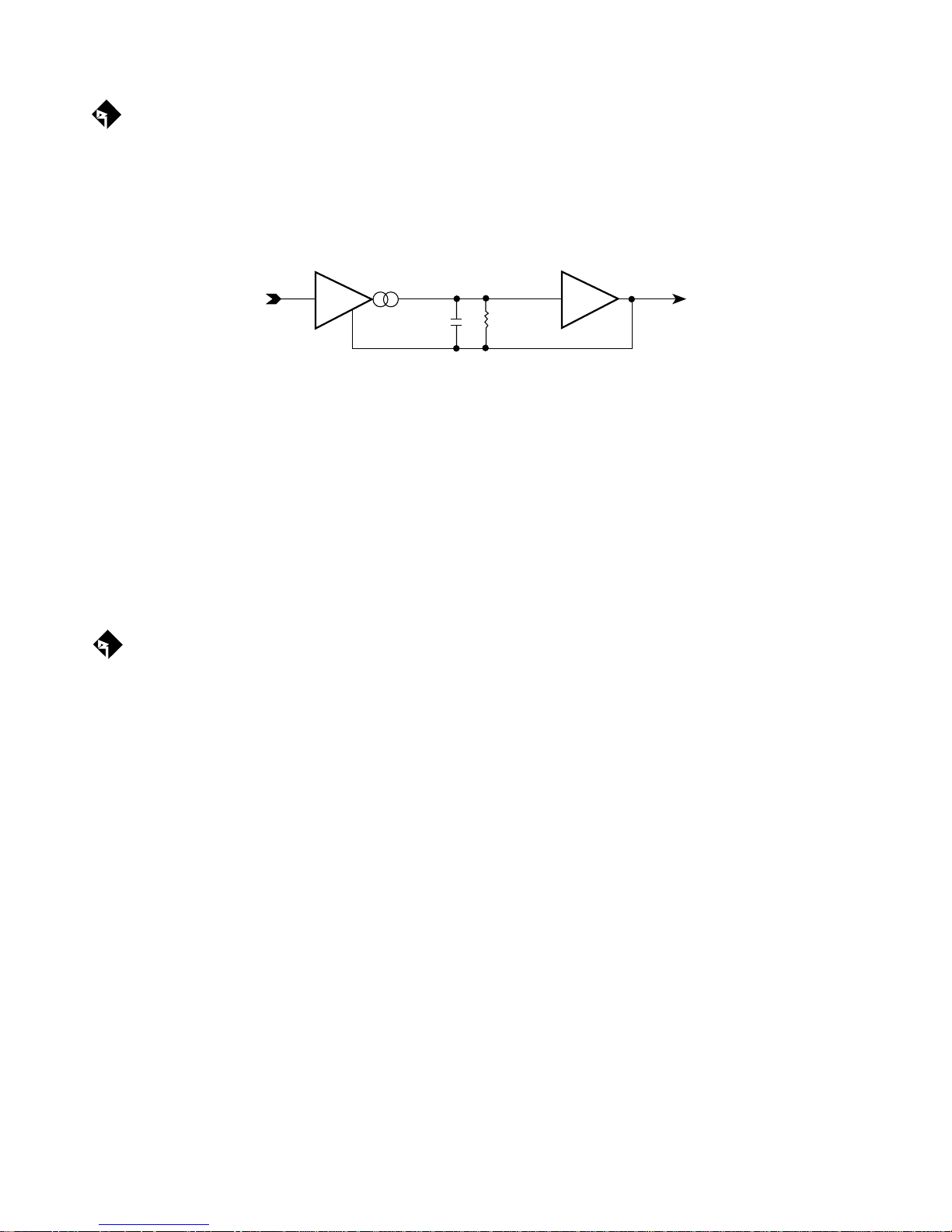
The trans•nova (TRANSconductance NOdal Voltage Amplifier) is a patented circuit that allows the audio
signal to pass through the amplifier at low voltage. Each amplifier channel utilizes its own “fully floating”
power supply and is configured to increase power gain. The increase in power gain allows the driver stage to
operate at a lower voltage. A low voltage drive stage is the same principle used in high quality preamplifiers
to produce high linearity and wide bandwidth.
E-I I-E
trans•nova circuitry
The resulting design utilizes an output stage with a simpler gain structure and a shorter signal path than
conventional high voltage (bi-polar) designs. The number of stages is reduced from five or more to three. The
output stage is further refined into a trans-impedance stage (current to voltage converter) to achieve a short
loop (fast) negative feedback. The output stage is driven cooperatively by a transconductance stage (voltage
to current converter).
THE RESULT: Superior sound quality, greater efficiency and higher reliability.
DIAMOND (U.S. patent 5,673,000)
®
DIAMOND (Dynamically Invariant AMplification Optimized Nodal Drive) is an important advance in
circuit design which reduces high frequency distortion. DIAMOND combines the linearity of Class A
operation with the current headroom of a Class B system by operating the MOSFET driver stage with 20dB
or more of current headroom, whereas traditional drivers have only 6dB of current headroom. The result is
a dramatic reduction in high frequency distortion, combined with improved ultrasonic stability.
THE RESULT: Colorless high frequency reproduction and greater inherent stability.
– 2 –
 Loading...