

Page 1

DOC026.52.00794
si792 P
si792x P
si792x P-FF
si792x P-PA
pH/ORP
2-Wire Transmitters
USER MANUAL
December 2007, Edition 1
© HACH Company, 2007. All rights reserved. Printed in Germany.
Page 2

2
Page 3

Table of Contents
Table of Contents ........................................................................ 1
Section 1 Specifications.........................................................5
Section 2 General information...........................................11
2.1 Safety information ....................................................................11
2.1.1 Use of hazard information.................................................11
2.1.2 Precautionary labels..........................................................11
2.2 General product information..................................................... 13
2.2.1 Product overview...............................................................13
2.2.2 FDA 21 CFR part 11 Compliance (HART only)................. 13
2.2.2.1 Electronic signatures for si792 P series transmitters .14
2.2.2.2 Audit trail for si792 P series transmitters....................14
2.3 Product models ........................................................................14
Section 3 Installation..............................................................15
3.1 Hazardous location control drawings .......................................16
3.2 Unpacking the transmitter ........................................................16
3.3 Mechanical installation............................................................. 17
3.3.1 Transmitter assembly........................................................17
3.3.2 Mounting ...................................................... ..................... 18
3.3.2.1 Wall mount.................................................................18
3.3.2.2 Panel or pipe mount (optional)................................... 18
3.4 Wiring Safety Information.........................................................20
3.5 Electrical installation................................................................. 21
3.5.1 Wire preparation................................................................ 21
3.5.2 Power and communication connections............................23
3.5.2.1 si792 P and si792x P (4–20 mA/HART) wiring ..........24
3.5.2.2 si792x P-FF and si792x P-PA wiring..........................25
3.5.3 Sensor wire connection.....................................................25
3.5.3.1 Hach combination pH/ORP sensors wiring................26
3.5.3.2 pH/ORP sensors with solution ground wiring.............27
3.5.3.3 Differential pH/ORP sensor wiring .............................28
3.6 HART communication connection............................................29
1
Page 4

Table of Contents
Section 4 Interface and navigation..................................31
4.1 si792(x) P (4–20 mA/HART) interface......................................31
4.2 si792x P-FF and si792x P-PA interface ...................................32
4.3 Display......................................................................................33
Section 5 Operation—4–20 mA/HART............................35
5.1 Measure mode .........................................................................35
5.2 Configuration............................................................................35
5.2.1 Output configuration..........................................................36
5.2.1.1 Output range ..............................................................37
5.2.1.2 Time averaging filter...................................................37
5.2.1.3 Output signal during errors.........................................38
5.2.1.4 Output signal during HOLD........................................38
5.2.2 Temperature compensation configuration.........................39
5.2.3 Calibration mode configuration..........................................40
5.2.4 Alarm settings configuration..............................................40
Section 6 Operation—Foundation Fieldbus................41
6.1 Configuration............................................................................41
6.1.1 Configuration steps ...........................................................41
6.1.2 Configuration menu...........................................................42
6.2 Foundation Fieldbus communication........................................44
6.2.1 Standard resource block (RB)...........................................44
6.2.2 Standard analog input block (AI).......................................47
6.2.2.1 Operating modes........................................................47
6.2.2.2 Set the parameter and units.......................................47
6.2.2.3 Data processing .........................................................48
6.2.2.4 Alarms........................................................................48
6.2.2.5 Bus parameters for the analog input block.................49
6.2.2.6 Cyclic measured value status.....................................52
6.2.2.7 Measured value limits—limit bits................................52
6.2.3 Transducer block...............................................................53
6.2.4 Calibration via Foundation Fieldbus..................................62
Section 7 Operation—Profibus PA...................................63
2
Page 5

Table of Contents
7.1 Configuration............................................................................63
7.1.1 Configuration steps ...........................................................63
7.1.2 Configuration menu...........................................................64
7.2 Profibus communication...........................................................65
Section 8 Calibration..............................................................69
8.1 Calibration................................................................................ 69
8.1.1 pH calibration ....................................................................69
8.1.1.1 Calibration with automatic buffer recognition .............70
8.1.1.2 Calibration with manual buffer entry........................... 71
8.1.1.3 Enter calibration data from calibrated probes ............72
8.1.1.4 Calibration by comparison— si792 (x) P (HART) and
si792x P-FF only.................................................................73
8.1.1.5 Zero adjustment for ISFET probes—For si792(x) P
(HART) and si792x P-FF only.............................................74
8.1.2 ORP calibration................................................................. 75
8.2 Temperature probe adjustment................................................77
Section 9 Maintenance...........................................................79
9.1 Cleaning the instrument ...........................................................79
9.2 Sensor maintenance ................................................................79
Section 10 Troubleshooting................................................81
10.1 Sensoface ..............................................................................81
10.2 Sensocheck............................................................................81
10.3 Error codes.............................................................................82
10.4 Calibration errors....................................................................84
10.5 Diagnostic functions............................................................... 86
Section 11 Parts and accessories.................................... 87
11.1 si792 P series versions ..........................................................87
11.2 Accessories............................................................................87
Section 12 Contact information.........................................89
Section 13 Limited warranty ...............................................92
Appendix A Buffer tables......................................................95
3
Page 6

Table of Contents
Appendix B Passcode editor............................................103
Index................................................................................ ...............105
4
Page 7

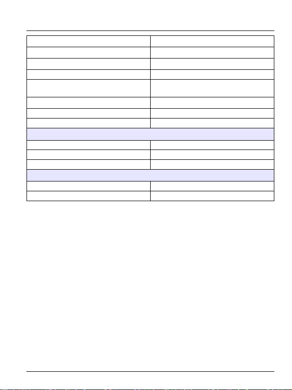
Section 1 Specifications
Specifications are subject to change without notice.
Transmitter
Composition PBT (polybutylene terephthalate)
Display LCD
Fittings
Power requirements—si792 P and
si792x P, (4–20 mA/HART)
Power requirements—FF and
Profibus PA
Loop current—si792 P and si792x P,
(4–20 mA/HART)
Current consumption—FF and
Profibus PA
Maximum current in case of fault
(FDE)—FF and Profibus PA
Measurement error
2
3 knockouts for M20 x 1.5 strain reliefs
2 knockouts for ½ inch NPT or rigid
metallic conduit
14–30 VDC (30 VDC maximum)
FISCO bus supply: 9 to 17.5 VDC
Linear barrier: 9 to 24 VDC
4–20 mA floating;
3.80–22.00 mA specifiable
<13.2mA
<17.6mA
<0.3% of current value + 0.05 mA
5
Page 8

Specifications
si792 P 4–20 mA/HART transmitter:
US:
si792 P
FM listed for:
Class I, Division 2
si792x P; si792x P-FF; si792x P-PA
FM listed for:
Class I, Division 1, Groups A, B, C, D
Class II, Division 1, Groups E, F,
Class III, Division 1
Class I, Zone 0, AEx ia, Group IIC T4
Enclosure: Type 2
Certification (may not apply to all
sensors. Refer to the control drawing or
listing for certification information for
the sensor that is used)
Note: Hach differential pH/ORP
sensors are not ATEX certified.
Power output for pHD sensor adapter
Output averaging time constant (HART) 0–120 seconds
Output span allowed pH: 2.00 to 18.00; mV: 200 to 3000
Storage temperature –20 to 70 °C (–4 to 158 °F)
Operating temperature –20 to 55 °C (–4 to 131 °F)
Weight Approximately 1 kg
Canada:
si792 P CSA certified to:
Class I, Division 2
si792x P CSA certified and
si792x P-FF; si792x P-PA cFMus
certified to:
Class I, Division 1, Groups A, B, C, D
Class I, Division 2, Groups A, B, C, D
Sensor: Class I, Zone 0, Group IIC
Transmitter: Class I, Zone 1, Group IIC
Enclosure: Type 2
EU: si792x P; si792x P-FF;
si792x P-PA
ATEX Certification:
II 2 (1) G EEx ib (ia) IIC T6
EU: CE Marked to:
EMC Directive 2004/108/EC
ATEX Directive 94/ 9/EC
Enclosure: IP65
+3 V/0.5 MA –6 V/0.5 mA (5.0 to 5.2 V,
maximum 640 µA)
6
Page 9

Data retention
Passcodes
Sensocheck
Sensor monitor
Communications
HART communication
Foundation Fieldbus (FF_H1)
Specifications
Parameters and calibration data
>10 years (EEPROM)
Modifiable according to FDA 21 CFR
Part 11 “Electronic Signatures”
(HARTonly)
Sensocheck automatic monitoring of
glass and reference electrode (can be
disabled). Delay: 30 seconds.
Direct display of measured values from
sensor for validation (electrode
potential/temperature)
Digital communication by FSK
modulation of loop current, reading of
device identification, measured values,
status and messages, reading and
writing of parameters, start of product
calibration, signaling of configuration
changes according to FDA 21 CFR Part
11.
Bus-powered device with constant
current consumption. Cyclic and acyclic
data exchange. 1 resource block, 1
transducer block, 3 analog input
function blocks (switchable: pH, ORP,
temperature, R
asymmetry potential)
Execution time: 50 ms
Certified to ITK 4.6
Physical interface: to IEC 1158-2
Address range: 017 to 246
glass
, R
, slope,
ref
7
Page 10

Specifications
Bus-powered device with constant
current consumption. Cyclic and acyclic
data exchange. Physical block,
2 analog input function blocks,
2 discrete input blocks, logbook block,
alarm block.
PNO directive: PROFIBUS-PA,
Profibus-P A (DPV1)
Temperature input
Probe
Range, Pt100/Pt1000
Range, NTC 300 Ω –20.0 to 110.0 °C (–4 to 230 °F)
Resolution 0.1 °C; 0.1 °F
Measurement error
Temperature compensation of sample
pH/ORP inputs
pH/ORP
Glass/reference electrode input
Input resistance—glass electrode
1,2
Profile for Process Control Devices,
Version 3.0
Physical interface: MBP-IS
(Manchester Bus Powered–Intrinsically
Safe) to IEC 1158 -2 (DIN-EN 61158-2)
Connection: via segment coupler to
SPC, PC, PCS
Address range: 1 to 126
Pt100/PT1000/NTC 300 Ω (selectable),
2-wire connection
si792 P; si792x P; si792x P-FF:
–20.0 to 200.0 °C (–4 to 392 °F)
2x P-PA:
si79
–20.0 to 150.0 °C (–4 to 302 °F)
<0.5 K
(<1 K for Pt100; <1 K for NTC >100 °C)
Linear –19.99 to 19.99%/K
(25 °C reference temperature)
Input for Combination or Differential
pH/ORP Sensors
IEC 746 Part 1, at nominal operating
conditions
12
>0.5 x 10
Ω
8
Page 11
Specifications
Input resistance—reference electrode
Input current—glass electrode
Input current—reference electrode
Measurement range –1500 to 1500 mV
Measurement error—pH
Measurement error—mV
1,2
1,2
Display range—pH –2.00 to 16.00 pH units
Display range—ORP –1999 to 1999 mV
pH sensor calibration
Offset range ± 60 mV
Slope range 85 to 103% (47.5 to 61 mV/pH unit)
Calibration timer 0 to 9999 hours
ORP sensor calibration (si792 P, si792x P and si792x P-FF only)
Calibration range –700 to 700 mV
Calibration timer 0 to 9999 hours
1
(± 1 count plus sensor error)
2
IEC 746 Part 1, at nominal operating conditions
10
–12
–10
Ω
A
A
>1 x 10
<2 x 10
<1 x 10
<0.02 pH units plus sensor error;
TC: 0.002 pH/K
<1 mV plus sensor error; TC: 0.1 mV/K
9
Page 12

Specifications
10
Page 13

Section 2 General information
2.1 Safety information
Please read this entire manual before unpacking, setting up, or
operating this equipment. Pay attention to all danger and caution
statements. Failure to do so could result in serious injury to the operator
or damage to the equipment.
To ensure that the protection provided by this equipment is not
impaired, do not use or install this equipment in any manner other than
that specified in this manual.
2.1.1 Use of hazard information
DANGER
Indicates a potentially or imminently hazardous situation which, if
not avoided, could result in death or serious injury.
CAUTION
Indicates a potentially hazardous situation that may result in
minor or moderate injury.
Important Note: Information that requires special emphasis.
Note: Information that supplements points in the main text.
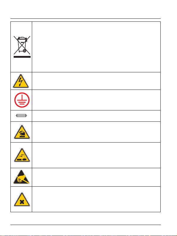
2.1.2 Precautionary labels
Read all labels and tags attached to the instrument. Personal injury or
damage to the instrument could occur if not observed. A symbol, if
noted on the instrument, will be included with a danger or caution
statement in the manual.
This symbol, if noted on the instrument, references the instruction
manual for operation and/or safety information.
11
Page 14
General information
Electrical equipment marked with this symbol may not be d isposed of
in European public disposal systems after 12 August of 2005. In conformity with European local and national regulations (EU Directive
2002/96/EC), European electrical equipment users must now return
old or end-of life equipment to the Pro ducer for disposal at no charge
to the user.
Note: For return for recycling, please contact the equipment
producer or supplier for instructions on how to return end-of-life
equipment, producer-supplied electrical accessories, and all auxiliary
items for proper disposal.
This symbol, when noted on a product enclosure or barrier, indicates
that a risk of electrical shock and/or electrocution exists.
This symbol, when noted on the product, identifies the location of the
connection for Protective Earth (ground).
This symbol, when noted on the product, identifies the location of a
fuse or current limiting device.
This symbol, when noted on the product, ident ifie s a risk of chemical
harm and indicates that only individuals qualified and traine d t o work
with chemicals should handle chemicals or perform maintenance on
chemical delivery systems associated with the equipment.
This symbol, when noted on the product, ident ifies th e pr esence of a
strong corrosive or other hazardous substance and a risk of chemical
harm. Only individuals qualified and trained to work with chemicals
should handle chemicals or perform maintenance on chemical delivery systems associated with the equipment.
This symbol, when noted on the product, indicated the presence of
devices sensitive to Electro-static Discharge (ESD) and indicated
that care must be taken to prevent damage with the equipment.
This symbol, when noted on the product, ident ifies th e pr esence of a
noxious substance and a risk of chemical harm. Only individuals
qualified and trained to work with chemicals should handle chemicals
or perform maintenance on chemical delivery systems associated
with the equipment.
12
Page 15

General information
2.2 General product information
2.2.1 Product overview
The si792 P series transmitters are used for pH/ORP and temperature
measurement in industry, environment, food processing and sewage
treatment. This manual describes the installation, operation and
maintenance for standard and EU models of the si792 P series
transmitters.
The molded transmitter enclosure can be attached to a panel, wall, post
or pipe railing. The optional hood (see Accessories on page 87)
provides protection against direct weather exposure and
mechanical damage.
Three communication protocols are available for the si792 transmitter:
• 4–20 mA/HART—Models si792(x) P, includes the si792 P and
si792x P models
• Foundation Fieldbus—si792x P-FF
• Profibus PA—si792x P-PA
This user manual includes instructions for all three protocols.
Important Note: An ‘x’ in the model number is an indication of an
instriniscally safe (IS) instrument.
2.2.2 FDA 21 CFR part 11 Compliance (HART only)
In the directive “Title 21 Code of Federal Regulations, 21 CFR Part 11,
Electronic Records; Electronic Signatures” the US American health
agency FDA (Food and Drug Administration) regulates the production
and processing of electronic documents for pharmaceutical
development and production. The features described in section 2.2.2.1
and section 2.2.2.2 make the transmitter compliant with the
requirements of FDA 21 CFR Part 11.
13
Page 16

General information
2.2.2.1 Electronic signatures for si792 P series transmitters
Device functions are protected by passcode access, which prevents
unauthorized modification of device settings or manipulation of
measurement results. Passcodes may be used as electronic
signatures. Passcodes can be edited with the passcode editor
(Appendix B on page 103).
2.2.2.2 Audit trail for si792 P series transmitters
The si792 series can automatically track all changes to the device
settings. Each change is tagged with a Configuration Change flag,
which is documented using HART communication. Altered device
settings or parameters can be retrieved from the transmitter using
HART communication.
2.3 Product models
The si792 P series instruments are programmed at the factory with
default settings for specific sensors and probes. The default settings,
chosen to accommodate regional safety standards, can be changed by
the user.
See Parts and accessories on page 87 for a list of instrument models.
14
Page 17

Section 3 Installation
DANGER
Explosion hazard. The installation and commissioning of this
equipment must only be carried out by trained personnel.
DANGER
Explosion hazard. Never connect items to the transmitter that are
not specified on the control drawing. Do not connect or
disconnect any equipment unless power has been switched off or
the area is known to be non-hazardous.
DANGER
Explosion hazard. The safety of the transmitter may be impaired if
any of the following conditions have occurred:
• visible damage
• storage above 70 °C for prolonged periods
• exposure to severe transport stresses
• previous installation
• failure to operate properly
If any of these conditions have occurred, return the device to the
manufacturer for recertification.
DANGER
Explosion hazard. pHD sensors (PDxxx and RDxxx) must have a
serial number greater than 0712431582 to be used in C1D1
hazardous locations. Check the serial number of the pHD sensor
before wiring the sensor to si792x P, si792x P-FF or
si792x P-PA instruments.
The si792 and si792x transmitters differ in hazard classification. The
si792 transmitter is designed for non-hazardous or Class I, Division 2,
Groups A, B, C, D hazardous locations. The si792x transmitter is
designed for Class I, Division 1, Groups A, B, C, D hazardous locations.
Refer to the control drawing or listing applicable to the site location.
15
Page 18

Installation
For outdoor installation, use of a protective hood or sunshield is
recommended (section 11.2 on page 87).
Installation of the si792x in an outdoor hazardous location per FM or
CSA control drawings requires a suitable enclosure and must follow
NEC guidelines. Refer to NEMA 250 to determine enclosure needs.
3.1 Hazardous location control drawings
Before installation, review the applicable Hazardous Location Control
Drawings or ATEX EC-type Examination Certificates included with the
instrument and on the provided documentation CD. Follow all
regulations specified for the installation location.
Refer to the documentation CD for manuals provided in
other languages.
3.2 Unpacking the transmitter
Check the shipment for transport damage and make sure all
components have been shipped complete. The package includes:
• Display module • Bag of hardware and fasteners
• Back enclosure • Test report and user manual
16
Page 19
Installation
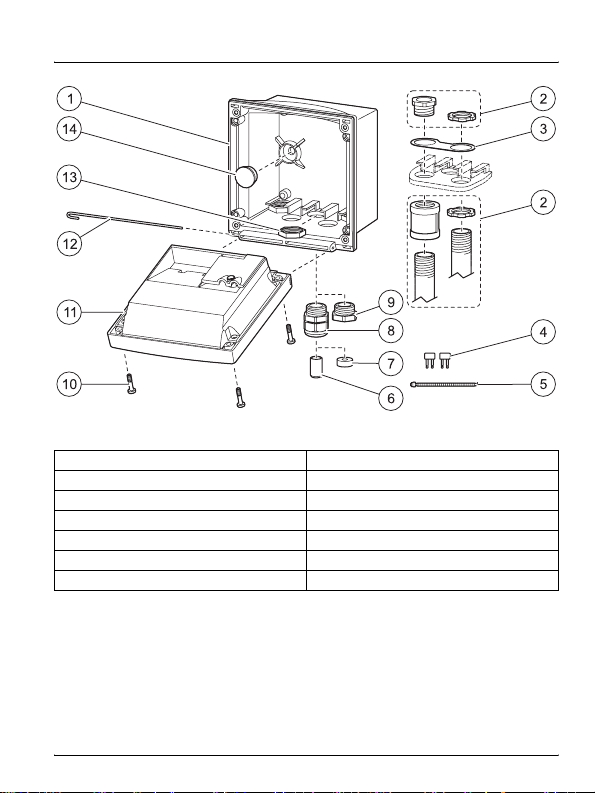
Figure 1 Instrument Components
1 Back enclosure 8 Strain relief (3x)
2 Optional conduit hardware 9 Filler plug (3x)
3 Conduit washer 10 Enclosure screw (4x)
4 Jumper (2x) 11 Display module
5 Cable tie (3x) 12 Hinge pin
6 Sealing insert 13 Hex nuts (5x)
7 Rubber reducer 14 Sealing plug (2x)
3.3 Mechanical installation
3.3.1 Transmitter assembly
Refer to Figure 1 and the following instructions to assemble the
transmitter.
17
Page 20

Installation
1. Insert the strain relief fittings in the holes of the back enclosure and
secure with the hex nuts (Figure 2).
2. Insert the conduit hardware or plugs in the back enclosure and
secure with the hex nuts.
3. Attach the display module to the back enclosure using the hinge pin.
3.3.2 Mounting
Refer to the following sections to mount the transmitter on a wall, panel
or pipe.
3.3.2.1 Wall mount
1. Use a punch to open the two wall-mount holes in the back enclosure
(Figure 2).
2. Drill holes in the wall suitable for the user-supplied mounting bolts.
3. Attach the back enclosure to the wall using two customer-supplied
bolts.
4. Insert the clear plastic plugs into the mounting holes.
3.3.2.2 Panel or pipe mount (optional)
Refer to Figure 2 and the instructions supplied with the panel and pipe
mounting kits (see Accessories on page 87).
18
Page 21
Installation
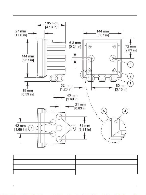
Figure 2 Wall attachment dimensions
1 Breakout for wall mounting (2x) 5 Groove for panel mount gasket
2 Hole for pipe mounting (4x) 6 Strain relief opening (3x)
3 Strain relief (3x)
4 Breakout for panel mounting
7 S train relief or ½ i nch conduit opening
(2x) Ø 21.5 mm [0.85 in]
19
Page 22

Installation
3.4 Wiring Safety Information
When making any wiring connections to the instrument, the following
warnings and notes must be adhered to, as well as any warnings and
notes found throughout the individual installation sections. For more
safety information refer to section 2.1 on page 11.
DANGER
Always disconnect power to the instrument when making any
electrical connections.
Electrostatic Discharge (ESD) Considerations
To minimize hazards and ESD risks, maintenance procedures not
requiring power to the analyzer should be performed with power
removed.
Delicate internal electronic components can be damaged by static
electricity, resulting in degraded instrument performance or eventual
failure.
The manufacturer recommends taking the following steps to prevent
ESD damage to the instrument:
• Before touching any electronic components (such as printed circuit
cards and the components on them) discharge static electricity from
the body by touching an earth-grounded metal surface such as the
chassis of an instrument or a metal conduit or pipe.
• To reduce static build-up, avoid excessive movement. Transport
static-sensitive components in anti-static containers or packaging.
• To discharge static electricity from the body and keep it
discharged, wear a wrist strap connected by a wire to earth
ground.
• Handle all static-sensitive components in a static-safe area. If
possible, use anti-static floor pads and work bench pads.
20
Page 23

Installation
3.5 Electrical installation
DANGER
Explosion hazard. Do not connect any components that are not
specified for the device. Always refer to the Hazardous Location
Control Drawing.
Prerequisites:
• Review the applicable control drawing or EC-type Examination
certificate.
• Review the electrical code regulations
• Review the regulations for electrical installations in hazardous
locations (e.g. EN 60079-10/EN 60079-14; 97/9/EC directive;
NEC; CEC; Profibus Technical Guidelines)
• Remove power or confirm non-hazardous status before making
any connections
• Confirm that the intrinsic safety of the device is maintained when
connected to other equipment such as a power supply unit.
3.5.1 Wire preparation
To remove the terminal blocks from the transmitter for sensor wiring:
1. Insert a flat screwdriver between the terminal block and the
transmitter body.
2. Use the screwdriver as a lever to lift the terminal block off the
connectors (see Figure 3 on page 22).
21
Page 24
Installation
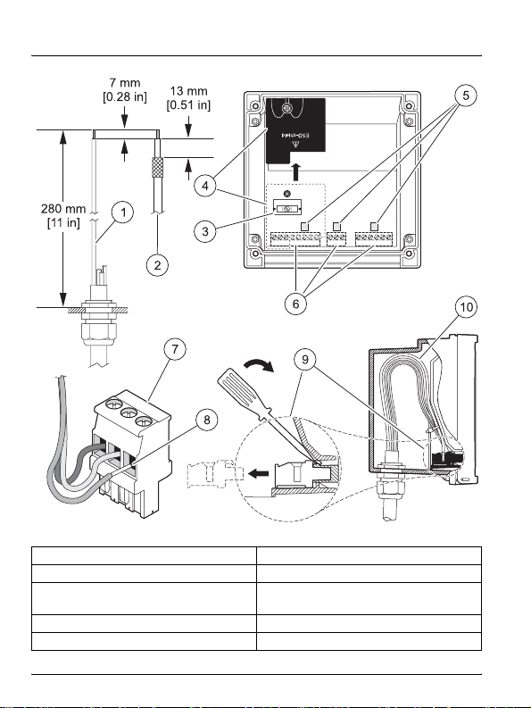
Figure 3 Wire preparation and insertion
1 Stripping lengths for cables 6 Terminals (vary by model number)
2 Stripping lengths for coaxial cables 7 Typical terminal
Cable shield connection
3
Note:
Do not connect to earth ground.
4 ESD shield removed 9 Removing terminal with screwdriver
5 Areas for screwdriver to pry terminal 10 Cable loop position in housing
8 Seat insulation against connector
22
Page 25

Installation
3.5.2 Power and communication connections
DANGER
Explosion hazard. The AC power source for the power supply unit
cannot exceed 250 VAC. Do not connect the transmitter directly to
an AC power source.
DANGER
Explosion hazard. The output voltage of the power supply unit
cannot exceed 30 VDC. The si792x transmitter must be connected
to an appropriately certified explosion-proof power supply unit.
Refer to "associated apparatus" in the control drawing or to the
EC-Type Examination Certificate for input ratings.
Prerequisites
• Trained personnel only must install or commission the
equipment.
• Follow the instructions in this user manual and the applicable
local and national codes.
• Observe the technical specifications and input ratings during
installation.
• Disconnect all power sources during wiring and installation.
• Use single wires/flexible leads up to 2.5 mm (AWG 14) for
connection to terminals.
• Do not damage the wire when stripping the insulation.
• All parameters must be set by a system administrator (Authority
Having Jurisdiction) before commissioning.
23
Page 26
Installation
3.5.2.1 si792 P and si792x P (4–20 mA/HART) wiring
DANGER
Explosion hazard. Never connect items to the transmitter that are
not specified on the control drawing/ATEX EC-type certificate.
Use Figure 4 and Table 1 to connect the power supply to the si792 P
and si792x P (4–20 mA/HART)..
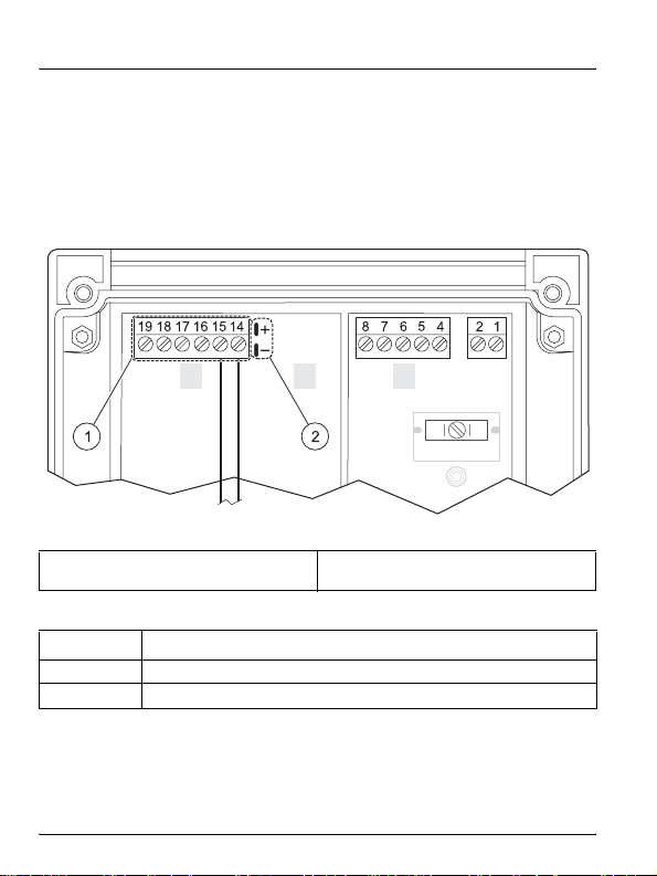
Figure 4 si792(x) P wiring
1 Wiring terminals—see Table 1
Table 1 Terminal assignments—si792(x) P
TerminalNo. Assignment
14 4–20 mA output (–)
15 4–20 mA output (+)
2 HART connection (see warnings in
section 3.6 on page 29)
24
Page 27
Installation
3.5.2.2 si792x P-FF and si792x P-PA wiring
Use Figure 5 and Table 2 to connect power and communication to the
si792x P-FF (Foundation Fieldbus) or si792x P-PA (Profibus).
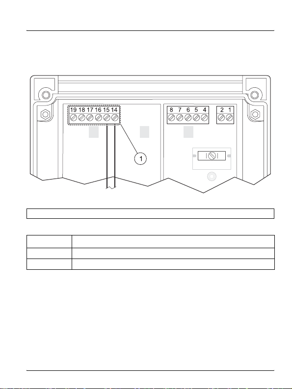
Figure 5
1 Wiring terminals—see Table 2
Table 2 Terminal assignments—si792x P-FF and si792x P-PA
Terminal No. Assignment
14 Connection from FF or Profibus PA (–)
15 Connection from FF or Profibus PA (+)
si792x P-FF and si792x P-PA wiring
3.5.3 Sensor wire connection
Important Note: Do not connect earth ground to the shield connector in
the transmitter. Connect the cable shields to the shield connector.
Refer to the following sections to connect the transmitter to a sensor:
• Hachcombination pH/ORP sensors—section 3.5.3.1 on page 26
• pH/ORP solution ground sensors—section 3.5.3.2 on page 27
• pH/ORP differential sensors—
section 3.5.3.3 on pag e 28
25
Page 28
Installation
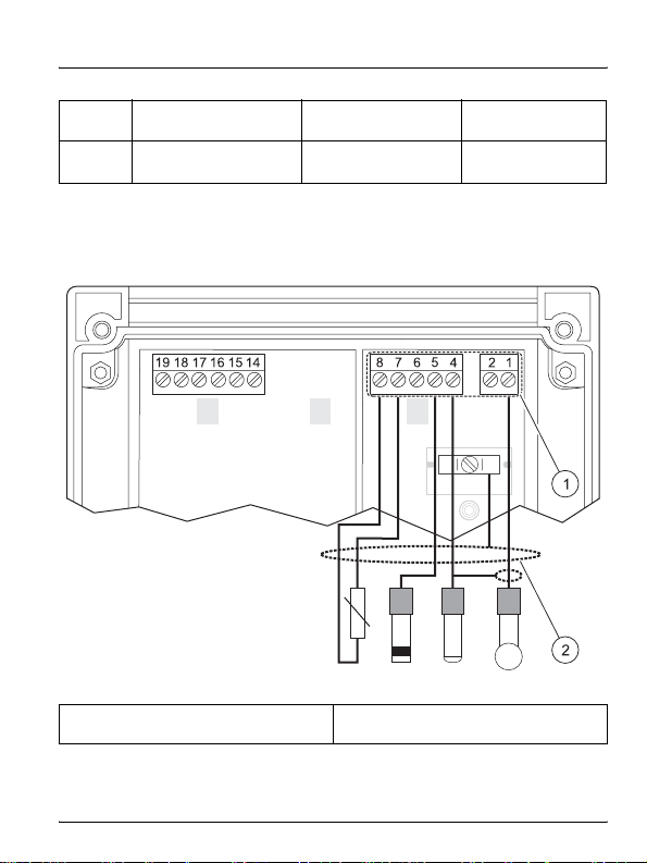
3.5.3.1 Hach combination pH/ORP sensors wiring
1. Install the jumpers shown in Figure 6.
2. Use Table 3 to wire the sensor to the transmitter.
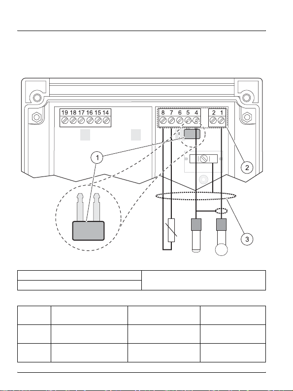
Figure 6 Wiring for Hach combination pH/ORP sensors
1 Jumper between terminal 4 and 5
2 Wiring terminals—see Table 3
Table 3 Terminal assignments—pH/ORP sensors
Terminal
Assignment
No.
1 Measure electrode
4 Reference electrode braided coaxial shield
Cable shield connection
3
Note:
Do not connect to earth ground.
Hach PC and RC
series color
coaxial cable center
wire
Six-plug
connection
coaxial cable center
wire
braided coaxial
shield
26
Page 29
Installation
Table 3 Terminal assignments—pH/ORP sensors (Continued)
RTD (resistive temp
7
device)
RTD (resistive temp
8
device)
3.5.3.2 pH/ORP sensors with solution ground wiring
Use Figure 7 and Table 4 to wire the sensor to the transmitter.
red green
white white
Figure 7 Wiring for pH/ORP sensors with solution ground
2
1 Wiring terminals—see Table 4
Cable shield connection
Note:
Do not connect to earth ground.
27
Page 30
Installation
Table 4 Terminal assignments—sensors with solution ground
TerminalNo. Assignment
1 Measure electrode
4 Reference electrode
5 Solution ground
7 RTD (resistive temperature device)
8 RTD (resistive temperature device)
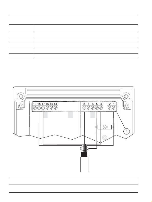
3.5.3.3 Differential pH/ORP sensor wiring
Use Figure 8 and Table 5 on page 29 to wire the sensor to
the transmitter. The pHD sensor has 7 wires (2 shield wires). The LCP
sensor has 6 wires (1 shield wire).
Figure 8
1 Wiring terminals—see Table 5 on page 29
Wiring for differential pH/ORP sensors (PDXXX/RDXXX)
28
Page 31

Installation
Table 5 Terminal assignments—differential sensors
Terminal No. Assignment Hach wire color
1 Measure electrode (pHD is Reference) red
4 Reference electrode (pHD is Measure) green
Cable shield connections (2 shield wires for
5
Hach pHD, 1 shield wire for Hach LCP)
Note:
Do not connect to earth ground.
8 RTD (resistive temperature device) yellow
17 –6 V white
18 GND black
shield
3.6 HART communication connection
DANGER
Explosion hazard. Never connect items to the transmitter that are
not specified on the control drawing. Do not connect or
disconnect any equipment unless power has been switched off or
the area is known to be non-hazardous.
DANGER
The si792x transmitter must be used with an explosion-proof
HART communication device. Refer to the appropriate control
drawing for the location of the HART (Rosemount) device.
The handheld HART communication device can only be connected to
the transmitter in US Class I, Division 1 classified locations (permitted
only by FM). Do not connect the handheld Hart communication device
to the transmitter in any Zone or Canadian Class I, Division 1 classified
location. Refer to Figure 4 on page 24 for the connector location.
29
Page 32

Installation
30
Page 33

Section 4 Interface and navigation
The si792 transmitter user interface contains a display, indicators and
keys for navigation and menu selection.
4.1 si792(x) P (4–20 mA/HART) interface
Use the arrow and enter keys to scroll through the menu and change
settings. Use the indicators to identify which mode the transmitter is in.
Refer to Figure 9 to identify the keys and indicators of the si792(x) P.
Figure 9 User interface—si792( x) P
1 Calibration key 7 Wash mode indicator (not available)
2 Configure key 8 Configuration mode indicator
3 Measure mode indicator 9 Up arrow key
4 Calibration mode indicator 10 Right arrow key
5 Alarm indicator
6 Display
11 Enter key
31
Page 34

Interface and navigation
4.2 si792x P-FF and si792x P-PA interface
Refer to Figure 10 to identify the keys and indicators of the si792x P-FF
and si792x P-PA.
Figure 10 User interface—
1 Measure key 7 Communication indicator
2 Calibration key 8 Configuration mode indicator
3 Measure mode indicator 9 Up arrow key
4 Calibration mode indicator 10 Right arrow key
5 Alarm indicator 11 Enter key
6 Display 12 Configuration mode
32
si792x P-FF and si792x P-PA
Page 35

Interface and navigation
4.3 Display
Figure 11 identifies all of the possible icons and symbols that may be
seen in the si792 transmitter display.
Figure 11 Display
1 Passcode 13 Secondary display
2 Temperature 14 Alarm mode
3 4–20 mA/HART output 15 Manual temperature on
4 Limit values (FF and Profibus PA) 16 Calibration mode
5 Alarm 17 Hold mode active
6 Sensocheck—probe error 18 Hourglass (waiting indication)
7 Calibration active 19 Measure mode active
8 Calibration interval 20 Calibration complete
9 Parameter display 21 Calibration—zero or first point
10 Enter prompt 22 Calibration—second point
11 Configuration mode
12 Main display
23 Sensofaces
33
Page 36

Interface and navigation
34
Page 37

Section 5 Operation—4–20 mA/HART
The following section describes how to operate the si792(x) P
(4–20 mA/HART) transmitters.
5.1 Measure mode
In the measure mode the display shows the pH or ORP value and the
temperature. The status bar is shown above the measure mode
indicator.
• To return to the measure mode from the configure menu, press
CONF and then ENTER.
• To return to the measure mode from the calibration menu, press
CAL and then ENTER.
Note: The waiting time for the stabilization of the measured value is
approximately 20 seconds.
5.2 Configuration
Use the configuration mode to specify the sensor, range and other
parameters for the system as shown in Table 6.
1. Press CONF and enter 1200 to enter the configuration mode.
2. Use the arrow and enter keys to change the settings. All settings
and options are shown in section 5.2.1, section 5.2.2,
section 5.2.3 and section 5.2.4.
Table 6 Configuration menu
Code Setting Passcode
o1 4–20 mA current output
tc Temperature compensation
CAL Calibration setup
AL. Alarm settings
1200
35
Page 38

Operation—4–20 mA/HART
To exit the configuration mode at any time, press
ENTER. The output current will be held for 20 seconds and the
measured value will be displayed.
Note: During configuration the transmitter remains in the Hold mode for
safety reasons. The loop current is held at the value specified in the
o1.HoLD menu option. The Sensoface icon is inactive. The
configuration mode indicator is displayed (Figure 11 on page 33).
5.2.1 Output configuration
An overview of the 4–20 mA output setup menu is shown in Table 7.
Table 7 Output setup menu—out.1
Select the parameter
o1.UniT
Specify the value for the 4 mA si gn a l (section 5.2.1.1)
o1.4mA
Specify the value for the 20 mA si g n a l (section 5.2.1.1)
o1.20mA
Set time averaging filter for reducing noise (section 5.2.1.2)
o1.Ftme Enter the time in seconds (0 to 120 seconds; default: 0 seconds)
Send a 22 mA signal during errors (section 5.2.1.3)
o1.FAil
Specify the value to output during HOLD periods (section 5.2.1.4)
o1.HoLD
pH (default) o1.EL (electrode)
ORP
Enter the pH value (–2.00 to 16.00 pH; default: 0 pH)
Enter the ORP value (–1999 to 1999 mV; default: 0 mV)
Enter the pH value (–2.00 to 16.00 pH; default: 14 pH)
Enter the ORP value (–1999 to 1999 mV; default: 14 mV)
On
Off (default)
LAST measured value (default)
FIXed
Enter the fixed value to output in mA (3.8 to 22 mA;
default: 21 mA)
CONF and then
MNU
Glass (default for EU version)
ISFET
pHD (default for standard ver-
sion; for pHD and LCP sensors)
36
Page 39

Operation—4–20 mA/HART
Press
ENTER to access a menu item. Use the ARROW KEYS to edit
values. Press
acceptable range, “Err” will be displayed and the value will not be
accepted. T o exit the menu and return to the measurement mode, press
CONF and then ENTER.
Example: Set the 4 mA current output signal to 3 pH.
1. Press
Conf and then out.1MNU.
2. Press
show o1.UniT.
3. Press
show o1.4mA.
4. Use the
03.00 pH. Press
o1.20mA.
5. Press
5.2.1.1 Output range
The upper and lower end of the pH or ORP measurement range should
correspond to the 4 mA and 20 mA signals. For example, to set a range
of 3–12 pH, set the 4 mA signal to correspond to a pH value of 3 and
the 20 mA signal to correspond to a pH value of 12.
5.2.1.2 Time averaging filter
An averaging filter is available to reduce noise in the output signal. The
filter averages readings over a specified time interval. The time interval
can be set from 0 to 120 seconds (default: 0 seconds).
When set to 0 seconds, there is no signal averaging for noise reduction.
When set to 120 seconds, the current output value will be correspond to
the process signal averaged over the last 120 seconds. Increase the
time interval to reduce the noise in the output signal.
Note: The filter acts on the output signal but not on the displayed value.
ENTER to save the settings. If a value is outside of the
CONF, enter passcode: 1200, ENTER. The display will show
ENTER to access the output setup menu. The display will
ENTER, ENTER to show the 4 mA submenu. The display will
UP ARROW and RIGHT ARROW to edit the value to
ENTER to save the value. The display will show
CONF and then ENTER to exit the configuration menu.
37
Page 40

Operation—4–20 mA/HART
5.2.1.3 Output signal during errors
When an error condition occurs, a 22 mA output signal can be sent as
a notification (default: off).
5.2.1.4 Output signal during HOLD
The output signal during hold periods can be maintained at the last
measured value (Figure 12) or fixed at a specified value (Figure 13).
The allowable range for the fixed value is 3.4 to 22 mA.
Figure 12 Output signal during HOLD—last value
1 Output signal during HOLD 2 HOLD mode time span
Figure 13 Output signal during HOLD—fixed value
1 Output signal during HOLD 2 HOLD mode time span
38
Page 41

Operation—4–20 mA/HART
5.2.2 Temperature compensation configuration
An overview of the temperature compensation setup menu is shown in
Table 8.
Table 8 Temperature compensation setup menu—tc
Select temperature unit
tc.UnIT
Select temperature probe
tc.rTD
Temperature detection during measurement
tc.MEAS
Temperature detection during calibration
tc.CAL
pH only temperature compensation of process medium
tc.LIN Enter compensation (–19.99 to 19.99%/K; default: 0% /K)
Press
values. Press
°C (default)
°F
Pt100
Pt1000 (default for EU version)
NTC300 (default for standard version with pHD and LCP sensors)
Auto (default)
Manual
Auto (default)
Manual
Enter the temperature (–20 to 200 °C; default: 25 °C)
Enter the temperature (–4.0 to 392 °F; default: 25 °F)
Enter the temperature (–20 to 200 °C; default: 25 °C)
Enter the temperature (–4 to 392 °F; default: 25 °F)
ENTER to access a menu item. Use the ARROW KEYS to edit
ENTER to save the settings. If a value is outside of the
acceptable range, “Err” will be displayed and the value will not be
accepted. T o exit the menu and return to the measurement mode, press
CONF and then ENTER.
MNU
39
Page 42

Operation—4–20 mA/HART
5.2.3 Calibration mode configuration
An overview of the calibration setup menu is shown in Table 9. Refer to
Appendix A on page 95 for buffer tables.
Table 9 Calibration mode setup menu—CAL mnu
Select pH buffer set
–01–BUF Knick/Mettler-Toledo
–02–BUF Merck Titrisols, Riedel Fixanals
–03–BUF Ciba (94)
–04–BUF NIST technical buffers
CA.SOL
Enter calibration timer interval
CA.tiME
5.2.4 Alarm settings configuration
An overview of the alarm setup menu is shown in Table 10.
Select Sensocheck
AL.SnSO
Enter alarm delay
AL.dLY 0010 sec (default) Range: 0000–0600 sec
LED in Hold mode
AL.LED
–05–BUF NIST standard buffers
–06–BUF (default) HACH buffers
–07–BUF WTW technical buffers
–08–BUF Hamilton Duracal
MAN (manual entry, for buffers not listed in this table)
DAT—Entry of offset and slope of premeasured electrodes
Enter the time interval for calibration (0 to 9999 hours; default: 0 h
to disable timer)
Table 10 Output setup menu for alarm settings
CHECK ON
CHECK OFF (default)
HOLD ON LED blinks during hold
HOLD OFF LED off during hold
Continuous Sensocheck evaluation of probe
function
40
Page 43

Section 6 Operation—Foundation
Fieldbus
The following section describes how to operate the si792x Fieldbus
transmitter. The transmitter can be operated as follows:
• Direct interface with the transmitter (section 6.1)
• Foundation Fieldbus communication (section 6.2 on page 44)
6.1 Configuration
Use the configuration mode to specify the sensor, range and other
parameters for the system.
6.1.1 Configuration steps
Complete the following steps to configure the si792 transmitter.
1. Press MEAS + CAL and enter 1200 to enter the configuration
mode.
2. Use the arrow and enter keys to change the settings. All settings
and options are shown in section 6.1.2.
To exit the configuration mode at any time, press MEAS + CAL and
ENTER. The Hold mode will be active for 20 seconds and then the
then
measured value will be displayed.
Note: During configuration the transmitter remains in the Hold mode for
safety reasons. The Sensoface icon is inactive. The configuration mode
indicator is displayed (Figure 10 on page 32).
41
Page 44

Operation—Foundation Fieldbus
6.1.2 Configuration menu
Select the process variable
In.UnIT
Select electrode type
ln.SnSR
Select temperature unit
tc.UnIT
Select temperature sensor
tc.rTD
Select temperature during measurement
tc.MEAS
Select temperature during calibration
tc.CAL
Select TC process medium
tc.LIN –19.9–19.99 %/K (default: 00.00 %/K)
pH (default) Range: –2.00–16.00 pH
ORP Range: –1500 mV–1000 mV
Glass (default for EU version)
ISFET
pHD (default for standard version, with pHD and LCP sensors)
°C (default)
°F
PT100
PT1000 (default for EU version)
300 NTC (default for standard version, with pHD and LCP sensors)
Auto (default)
Manual
Auto (default)
Manual
°C (default: 25 °C) Range: –20–150 °C
°F Range: –004–0392 °F
°C (default: 25 °C) Range: –20–100 °C
°F Range: –004–0392 °F
42
Page 45

Operation—Foundation Fieldbus
6.1.2 Configuration menu (continued)
Select calibration mode / solution
-01-BUF Mettler-Toledo
-02-BUF Merck Titrisols, Riedel Fixanals
-03-BUF Ciba (94)
-04-BUF NIST technical buffers
CA.SOL
CA.timE CAL timer interval 0000–9999 h (default: 0000h)
Select Sensocheck
AL.SnSO
LED in Hold mode
AL.LED
Enter Fieldbus address (optional)
FF.ADR 0017–0031 BUS (default: 0026 BUS)
1
Use only when there is no bus connection. The transmitter will restart and set all
parameters to default values. Individual settings must be ent ered once more.
-05-BUF NIST standard buffers
-06-BUF (default) HACH buffers
-07-BUF WTW technical buffers
-08-BUF Hamilton
MAN (manual entry, for buffers not listed in this table)
CHECK ON
CHECK OFF (default)
HOLD ON LED blinks during hold
HOLD OFF (default) LED off during hold
Continuous Sensocheck evaluation of
sensor function
1
43
Page 46

Operation—Foundation Fieldbus
6.2 Foundation Fieldbus communication
Use the Foundation Fieldbus specification to set up and configure the
si792 transmitter. The communication parameters are listed in the
following sections. The sensor can be calibrated as described in
section 6.2.4 on page 62.
6.2.1 Standard resource block (RB)
The standard resource block describes the transmitter characteristics
(manufacturer, device name, operating status, global status). The
resource block must be in automatic mode for any of the other blocks to
operate. The bus parameters for the standard resource block (RB) are
shown in Table 11.
Table 11 Bus parameters—resource block (RB)
Parameter Description Default R/W
ST_REV Static revision 0 R
TAG_DESC TAG description R/W
STRATEGY Strategy 0 R/W
ALERT_KEY Alert key 0 R/W
Target
MODE_BLK
BLOCK_ERR Block error R
RS_STATE Resource state 1 R
TEST_RW Test R/W
DD_RESOURCE DD resource R
MANUFAC_ID Manufacturer ID 0x001D6D for Hach R
DEV_TYPE Device type 0x0064 R
DEV_REV Device revision 1 R
DD_REV DD revision 1 R
Actual —
Permitted OOS, Auto
Normal Auto
(out of service)
OOS
R/W
44
Page 47

Operation—Foundation Fieldbus
Table 11 Bus parameters—resource block (RB) (continued)
Parameter Description Default R/W
GRANT_DENY
HARD_TYPES Hardware type 1 R
RESTART Restart R/W
FEATURES Feature supported Reports/ Soft W Lock R
FEATURES Feature selected Reports/ Soft W Lock R/W
CYCLE_TYPE Cycle type
CYCLES_SEL Cycle selected
MIN_CYCLE_T Min cycle time
MEMORY_SIZE Memory size R
NV_CYCLE_T Non-volatile cycle time R
FREE_SPACE Free space R
FREE_TIME Free time R
SHED_RCAS R/W
SHED_ROUT R/W
FAULT_STATE Fault state R
SET_FSTATE Set fault state 1 R/W
CLR_FSTATE Clear fault state 1 R/W
MAX_NOTIFY Max notifications 20 R
LIM_NOTIFY Limit of notification 8 R/W
CONFIRM_TIME Confirmation time
WRITE_LOCK Write locking 1 (Unlocked) R/W
UPDATE_EVT
Grant 0 R/W
Deny 0 R/W
Scheduled/
Block Execution
Scheduled/
Block Execution
1
1600
/32 ms (50ms)
1
/32 ms
640000
Unacknowledged 0 R/W
Update state 0 R
Time stamp 0 R
Static revision 0 R
Relative index 0 R/W
R
R/W
R
R/W
45
Page 48

Operation—Foundation Fieldbus
Table 11 Bus parameters—resource block (RB) (continued)
Parameter Description Default R/W
Unacknowledged R/W
BLOCK_ALM
ALARM_SUM
ACK_OPTION
WRITE_PRI Write priority 0 R/W
WRITE_ALM
ITK_VER ITK_version 4 R
DEVICE_LOCK
Alarm state R
Time stamp R
Sub-code R
Value R
Current R
Unacknowledged R
Unreported R
Disabled R/W
Automatic acknowledge
option
Unacknowledged R/W
Alarm state R
Time stamp R
Sub-code R
Value R
Locks the device for local
access.
1 byte
Data type = uns8
Range:
0 (Unlocked)
1 (Locked)
0 (Disabled) R/W
0 (Unlocked) R /W
46
Page 49

Operation—Foundation Fieldbus
6.2.2 Standard analog input block (AI)
Three Analog Input Function Blocks provide for cyclic transmission of
measured values (currently measured value with status, alarm limits,
freely selectable process parameter).
6.2.2.1 Operating modes
Use the MODE_BLK parameter to set the following operating modes:
• OOS—out of service. If not write-protected, access to all
parameters is allowed.
• MAN—manual
• Auto—online, normal state
6.2.2.2 Set the parameter and units
Use CHANNEL to set the measured parameter and units (Table 12).
The corresponding measurement unit is selected in the UNITS
subparameter of XD_SCALE (Table 13 on page 49).
Table 12 Measurement parameters and units
Channel Parameter Unit
1pH pH
2ORP mV
3 Temperature
4 Glass impedance MΩ
5 Ref. impedance kΩ
6Slope %
7 Asymmetry potential mV
°C
°F
47
Page 50

Operation—Foundation Fieldbus
6.2.2.3 Data processing
Use the L_TYPE parameter to apply a linearization function to the data.
• Direct—data is sent directly from the TB to the AI without
processing. The units for the XD_SCALE and OUT_SCALE
parameters must be identical.
• Indirect—data from the TB is linearly scaled from the input scale
(XD_SCALE) to the output scale (OUT_SCALE).
• Indirect square root—data is rescaled from the input scale
(XD_SCALE) and recalculated using a root function. Then the
value is linearly scaled to the output scale (OUT_SCALE).
6.2.2.4 Alarms
The AI block can generate block alarms and limit alarms. Use the
ACK_OPTION parameter to specify if an alarm must be acknowledged.
When the measured value status is “bad”, the AI block BLOCK_ERR
parameter indicates an Input Failure.
• Block alarms—a block error will be reported via the
BLOCK_ERR parameter (simulate active, input failure, block
configuration error, out of service (OOS)). The BLOCK_ALM
parameter sends the alarm status to the control system.
• Li mit alar ms—the measured value OUT falls outside of the limit
values (HI_HI_LIM, HI_LIM, LO_LIM, LO_LO_LIM).
If an alarm occurs, evaluate the following bus parameters:
• OUT parameter (currently measured value) in the Al block
• LAST_ERROR parameter in the transducer block
• SENSOFACE_STATUS parameter in the transducer block
48
Page 51

Operation—Foundation Fieldbus
6.2.2.5 Bus parameters for the analog input block
The bus parameters for the analog input function block (AI) are shown
in Table 13.
Table 13 Bus parameters/analog input blocks (AI)
Parameter Description Default R/W
ST_REV Static Revision 0 R
TAG_DESC TAG Description R/W
STRATEGY Strategy 0 R/W
ALERT_KEY Alert Key 0 R/W
Target OOS
MODE_BLK
BLOCK_ERR Block Error R
PV
OUT
SIMULATE
XD_SCALE
OUT_SCALE
Actual —
Permitted OOS, Auto
Normal Auto
Process Value R
Status R
Measured Value R
Status R
Simulate Status R/W
Simulate Value R/W
Transducer S tatus R
Transducer Value R
Simulate Enable / Disable R/W
High Range 100 R/W
Low Range 0 R/W
Units Index 0 R/W
Decimal Point 0 R/W
High Range 100 R/W
Low Range 0 R/W
Units Index 0 R/W
Decimal Point 0 R/W
R/W
49
Page 52

Operation—Foundation Fieldbus
Table 13 Bus parameters/analog input blocks (AI) (continued)
Parameter Description Default R/W
GRANT_DENY
IO_OPTS IO Block Options 0 R/W
STATUS_OPTS Status Options
CHANNEL Channel 1 R/W
L_TYPE Linearization Type 0 R/W
LOW_CUT Low Cut Off 0 R/W
PV_TIME Filter Time 0 R/W
FIELD_VAL
UPDATE_EVT
BLOCK_ALM
ALARM_SUM
ACK_OPTION
AlARM_HYS Alarm Hysteresis 0.50% R/W
HI_HI_PRI High High Priority 0 R/W
HI_HI_LIM High High Limit INF R/W
HI_PRI High Priority 0 R/W
HI_LIM High Limit INF R/W
LO_PRI Low Priority 0 R/W
Grant 0 R/W
Deny 0 R/W
Percent Value R
Status R
Unacknowledged 0 R/W
Update State 0 R
Time Stamp 0 R
Static Revision 0 R
Relative Index 0 R
Unacknowledged 0 R/W
Alarm State 0 R
Time Stamp 0 R
Sub-code 0 R
Current 0 R
Unacknowledged 0 R
Unreported 0 R
Disabled 0 R/W
Automatic Acknowledge
Option
0R/W
50
Page 53

Operation—Foundation Fieldbus
Table 13 Bus parameters/analog input blocks (AI) (continued)
Parameter Description Default R/W
LO_LIM Low Limit –INF R/W
LO_LO_PRI Low Low Priorit y 0 R/W
LO_LO_LIM Low Low Limit –INF R/W
Unacknowledged 0 R/W
HI_HI_ALM
HI_ALM
LO_ALM
LO_LO_ALM
Alarm State 0 R
Time Stamp 0 R
Sub-code 0 R
Value 0 R
Unacknowledged 0 R/W
Alarm State 0 R
Time Stamp 0 R
Sub-code 0 R
Value 0 R
Unacknowledged 0 R/W
Alarm State 0 R
Time Stamp 0 R
Sub-code 0 R
Value 0 R
Unacknowledged 0 R/W
Alarm State 0 R
Time Stamp 0 R
Sub-code 0 R
Value 0 R
51
Page 54

Operation—Foundation Fieldbus
6.2.2.6 Cyclic measured value status
The cyclic measured value status is shown in Table 14.
Table 14 Cyclic measured value status
Priority Quality Sub-status
Low
Good
Uncertain
Bad
High Out of Service 00 01 11 xx 0 x 1C
Good Non-Specific 10 00 00 00 0 x 80
Good Active Advisory Alarm 10 00 10 xx 0 x 88
Good Active Critical Alarm 10 00 11 xx 0 x 8C
Uncertain Non-Specific 01 00 00 xx 0 x 40
Last Usable Value (LUV) 01 00 01 xx 0 x 44
Substitute-Set 01 00 10 xx 0 x 48
Initial Value 01 00 11 xx 0 x 4C
Sensor Conversion Not Accurate 01 01 00 xx 0 x 50
Engineering Unit Violation 01 01 01 xx 0 x 54
Sub-Normal 01 01 10 xx 0 x 58
Non-Specific 00 00 00 xx 0 x 00
Sensor Failure 00 01 00 xx 0 x 10
Device Value 00 00 11 xx 0 x 0C
Bin-coding
(no limit bits)
6.2.2.7 Measured value limits—limit bits
The respective status bit is set when a condition occurs (Table 15). The
status bit is reset when the condition no longer exists.
Table 15 Limit bit description
Bin coding of limit bits Description
00 OK
01 Low-limited
10 High-limited
11 Constant
Hexcoding
52
Page 55

Operation—Foundation Fieldbus
Range
The revision value is
incremented every
time a static
parameter in the
block is changed.
Data
type
6.2.3 Transducer block
The transducer block provides for acyclic data transmission. Calibration, configuration, and
maintenance commands coming from the control station are processed in the Transducer
Table 16 Transducer block bus parameters
Block. The bus parameters for the transducer block (TB) are shown in Table 16 (default values
are in bold type).
R2
The revision of the static data
associated with the function
block. Used by the host to
Parameter Description R/W Bytes
ST_REV
determine when to re-read the
R/W 32 Default: Text
static data.
The user description of the
intended application of the
TAG-DESC
block.
R/W 2 Default: 0
The strategy field can be used
to identify a grouping of blocks.
STRATEGY
Can be used for any purpose
by the user.
Identification number that may
R/W 1 Default: 0
be used by the host system to
sort alarms and other device
information.
ALERT_KEY
53
Page 56

Operation—Foundation Fieldbus
Available modes:
Automatic, Out Of
Service
Range
Data
type
(OOS), Manual
Default: 0
Default: 0
54
Allows the user to set the
Target, Permitted, and Normal
111
R/WRR/W
device mode. Displays the
1
R/W
Actual mode.
Target
Actual
Permitted
Normal
Reflects the error status
associated with the hardware or
11822
R2
software of the block. It is a bit
string so multiple errors may be
shown.
Unacknowledged Update Stat e
R
Time St amp S t atic Rev Relative
Index
11821
R
Unacknowledged Alarm State
Time Stamp Subcode Value
Table 16 Transducer block bus parameters (continued)
Parameter Description R/W Bytes
MODE_BLK
BLOCK_ERR
UPDATE_EVENT
BLOCK_ALM
Page 57

Range
Data
type
Operation—Foundation Fieldbus
Default: 65535 =
other
0 = pH
1 = ORP
DS-65
4
1
R4
Directory that specifies the
number and the starting indices
of the transducers in the
transducer block.
R1 Default: 0
A transducer block sub-code.
XD_ERROR contains the
highest priority alarm that has
been activated in the
TB_DETAILED_STATUS
parameter.
A directory that specifies the
R36
number, starting indices, and
DD item of IDs of the data
collection in each transducer
within a transducer block. Used
by the host for efficient transfer
of information.
R
Shows the pH value and status
Value
Status
Table 16 Transducer block bus parameters (continued)
TRANSDUCER_
DIRECTORY
Parameter Description R/W Bytes
TRANSDUCER_TYPE Identifies the transducer type. R 2
XD_ERROR
COLLECTION_
DIRECTORY
Output
PRIMARY_VALUE_TYPE pH/ORP R/W 2 uns16
PRIMARY_VALUE
55
Page 58

Operation—Foundation Fieldbus
Range
16pH
-2pH
1422 (pH)
2
0 = Glass
1 = ISFET
2 = pHD
Data
type
DS-68 –2–16
442
1
DS-68 –1500–1000mV
1
DS-65 –20–200 °C
1
56
R
Shows the range of the pv
High Range
Low Range
Unit Index
Decimal Point
R4
Process ORP value and status
Value
Status
R 2 uns 16 Default: 1243 = mV
R4
Process temperature value and
status
Value
Status
Table 16 Transducer block bus parameters (continued)
Parameter Description R/W Bytes
PRIMARY_VALUE_RANGE
SENSOR_TYPE_PH Glass, ISFET, pHD R/W 2 uns 16
SENSOR_MV Sensor output in mV R 2 float
SECONDARY_VALUE_1
SECONDARY_VALUE_
UNIT_1
ISO_POTENTIAL Isopotential pH value R 4 float Default: 7 pH
SECONDARY_VALUE_2
Page 59

Range
Data
type
Operation—Foundation Fieldbus
1001 = °C
1002 = °F
0 = Automatic
1 = Manual
0 = Automatic
1 = Manual
128 = Pt100
1
200 = Pt1000
1000 = NTC30021001 = NTC8.55
R/W 2 uns16
Degree C or degree F . Changes
the unit of temperature being
displayed and transmitted.
Indicates manual or automatic
temperature compensation.
R/W 1 uns8
Turns automatic pH sensor
temp. compensation on and off.
R/W 4 float –20–200 °C
Temperature value used in
manual temp. compensation
mode.
The constant temp. value used
to calculate pH in the manual
R/W 1 uns8
R/W 4 float –20–200 °C
temp. compensation mode
Indicates manual or automatic
mode of temperature
measurement for calibration.
Temperature value used in
manual temp. compensation for
R/W 2 uns16
calibration.
Type of temperature sensor.
The value entered must
correspond to the temp.
element in the pH sensor being
used.
Table 16 Transducer block bus parameters (continued)
Temperature
SECONDARY_VALUE_
UNIT_2
Parameter Description R/W Bytes
TEMP_SENSOR_COMP
TEMP_SENSOR_MAN_
VALUE
TEMP_SENSOR_CALIB
TEMP_SENSOR_CALIB_
MAN_VALUE
TEMP_SENSOR_TYPE
57
Page 60

Operation—Foundation Fieldbus
–19.99–19.99
Default: Typically
0.00, unless solution
pH temperature
compensation is
Range
Data
type
being used.
0–1000Ω
Default: 0Ω
58
Rate of change of solution pH
with temp, used for solution pH
temp. compensation.
CAL_MAN_PH_POINT_1
Entering a value augments the
R/W 4 float
temp. compensation to correct
for changes in the actual
solution pH with temp. This
value should correspond to the
known temperature
R/W 4 float
characteristics of the process
solution.
Sets the wire impedance of the
temp. sensor. T ypically 0 unless
the wire of the sensor gets too
long.
R/W 4 float –10–10K
Desired temperature reading,
used for temperature
measurement calibration. The
temp. value entered for a single
point temp. standardization.
R/W 4 float –2–16pH
pH of buffer solution used in a
manual buffer calibration.
Table 16 Transducer block bus parameters (continued)
Parameter Description R/W Bytes
TEMPERATURE_COEFF
TEMP_WIRE_IMPEDANCE
TEMP_SENSOR_CAL
Calibration
CAL_MAN_PH_POINT_1
Page 61

Range
Data
type
Operation—Foundation Fieldbus
80–103%
Default: Theoretical
value is 100% =
59.16mV/pH,
but the actual value
is determined by a 2
point buffer
calibration.
–60–60mV
Default: Theoretical
value is 0.00 mV, but
actual value will
depend upon the
characteristics of the
pH sensor field
–60–60mV.
0–9999h
Default: 0000 h =
disable
R/W 4 uns8 –2–16pH
pH of buffer solution used in a
manual buffer calibration.
The slope of the pH electrode in
R/W 4 float
%
R/W 4 float
The zero offset resulting from a
buffer calibration or a
R/W 4 float –700–700mV
R/W 4 float
standardization
The zero offset resulting from a
buffer calibration.
Sets the calibration timer (time
in which the device should be
calibrated).
Table 16 Transducer block bus parameters (continued)
CAL_MAN_PH_POINT_2
Parameter Description R/W Bytes
CAL_SLOPE_PH
CAL_ZERO_PH
CAL_OFFSET_ISFET Sets the offset of the ISFET. R/W 4 float –200–200mV
CAL_ZERO_ORP
CALIBRATION_TIMER
59
Page 62

Operation—Foundation Fieldbus
0 = BUF
1 = MAN
2 = DAT
1 = - 01 - BUF
2 = - 02 - BUF
3 = - 03 - BUF
4 = - 04 - BUF
5 = - 05 - BUF
6 = - 06 - BUF
7 = - 07 - BUF
8 = - 08 - BUF
0 = Nop
Range
Data
type
1 = Sample
0 = Nop
1 = Sample
60
R/W 1 uns8
Sets the buffer set for
CALIBRATION_MODE.= BUF
Starts th e 1st part of pH-product
R/W 1 uns8
calibration.
R 4 float –2–16pH
R/W 4 float –2–16pH
R/W 1 uns8
R 4 float –1500–1000mV
Shows the stored value of the
first step of pH-product
calibration
Sets the value for the 2nd part
of pH-product calibration.
Starts the 1st part of ORP-
product calibration.
Shows the stored value of the
first step of ORP-product
calibration.
Table 16 Transducer block bus parameters (continued)
CALIBRATION_MODE Sets the calibration mode. R/W 1 uns8
Parameter Description R/W Bytes
CALIBRATION_MODE_
BUFFER
CAL_SAMPLE_PRD_PH
CAL_SAMPLE_PRD_PH_
STORED_VAL
CAL_PRODUCT_PH
CAL_SAMPLE_PRD_ORP
CAL_SAMPLE_PRD_ORP_
STORED_VAL
Page 63

Range
Data
type
Operation—Foundation Fieldbus
–1500–1000mV
Default: ORP
0 = Off
1 = On
0 = Off
1 = On
0...100
Default: 0 = None
0 = Good
2 = Bad
R/W 4 float
Sets the value for the 2nd part
R/W 1 uns8
of ORPproduct calibration.
Enables or disables
Sensocheck.
Shows the current status of the
R 1 uns8
Sensoface.
Table 16 Transducer block bus parameters (continued)
CAL_PRODUCT_ORP
Parameter Description R/W Bytes
Alert
SENSOCHECK
ALARM_LED_MODE Sets the LED to HOLD mode. R/W 1 uns8
LAST_ERROR Shows the last error. R 2 uns16
SENSOFACE_STATUS
Identification and local parameter setting
SW_REV_LEVEL Software revision number R 2 uns8
Default for EU version2Default for standard version
HW_REV_LEVEL Hardware revision number R 1 uns8
1
61
Page 64

Operation—Foundation Fieldbus
6.2.4 Calibration via Foundation Fieldbus
The transmitter can be calibrated via Foundation Fieldbus using the
comparison or grab sample method.
pH
1. Make sure the system is configured for pH
(PRIMARY_VALUE_TYPE = pH).
2. Collect a grab sample and set CAL_SAMPLE_PRD_PH to sample.
The pH value of the sample is stored. After writing, the parameter is
automatically reset to NOP (no operation).
3. Read the parameter CAL_SAMPLE_PRD_PH_STORED_VAL. It
contains the stored value.
4. Measure the grab sample and write the lab value in
CAL_PRODUCT_PH. The device is now calibrated.
CAL_SAMPLE_PRD_PH_STORED_VAL is reset to zero.
Note: Calibration values can also be entered directly in the
CAL_SLOPE_PH and CAL_ZERO_PH parameters.
ORP
1. Make sure the system is configured for ORP
(PRIMARY_VALUE_TYPE = ORP).
2. Collect a grab sample and set CAL_SAMPLE_PRD_ORP to
sample. The ORP value of the sample is stored. After writing, the
parameter is automatically reset to NOP (no operation).
3. Read the parameter CAL_SAMPLE_PRD_ORP_STORED_VAL. It
contains the stored value.
4. Measure the grab sample and write the lab value in
CAL_PRODUCT_ORP. The device is now calibrated.
CAL_SAMPLE_PRD_ORP_STORED_VAL is reset to zero.
62
Page 65

Section 7 Operation—Profibus PA
The following section describes how to operate the si792x P-PA
transmitter. The transmitter can be operated as follows:
• Direct interface with the transmitter (section 7.1)
• Profibus PA communication (section 7.2 on page 65)
Note: Calibration must be completed by direct interface with the
transmitter.
7.1 Configuration
Use the configuration mode to specify the sensor, range and other
parameters for the system.
7.1.1 Configuration steps
1. Press MEAS + CAL and enter 1200 to enter the configuration
mode.
2. Use the arrow and enter keys to change the settings. All settings
and options are shown in section 7.1.2.
To exit the configuration mode at any time, press MEAS + CAL and
then
ENTER. The Hold mode will be active for 20 seconds and then the
measured value will be displayed.
Note: During configuration the transmitter remains in the Hold mode for
safety reasons. The Sensoface icon is inactive. The configuration mode
indicator is displayed (Figure 11 on page 33).
63
Page 66

Operation—Profibus PA
7.1.2 Configuration menu
Select process variable pH/mV
pH (default) Range: 0.00–14.00 A change of the process variable
mV Range: –1500–1500
Select the temperature unit
Auto °C (default) The measurement and
Auto
man
manAuto
Select the temperature sensor (auto)
Enter temperature of sensor (man)
Select Sensocheck
Auto °F
man °C
man °F
°C Auto man Recorded automatically during
°F Auto man
PT100
PT1000 (default for EU version)
300 NTC (default for standard version with pHD and LCP sensors)
BUS EXT
xxx.x °C (default: 025.0 °C)
xxx.x °F
CHECK ON
CHECK OFF (default)
requires a complete configuration
calibration are automatically
recorded when the temperature
sensor is connected
Manual input during
measurement and calibration
measurement
Manual input during calibration
External temperature during
measurement (°C)
Manual input during calibration
(°C)
Continuous Sensocheck
evaluation of sensor function
64
Page 67

Operation—Profibus PA
7.1.2 Configuration menu (continued)
Select the calibration mode
-01-BUF
-02-BUF
-03-BUF Ciba (94)
-04-BUF
-05-BUF
-06-BUF
(default)
-07-BUF
-08-BUF Hamilton
DAT
MAN
Enter cal timer interval
0000–9999 h (default: 0000 h (Off))
Enter Profibus address
Edit 0001–0126 (default: 0126)
Knick /Mettler
Toledo
Merck Titrisols,
Riedel Fixanals
NIST technical
buffers
NIST standard
buffers
HACH buffers
WTW technical
buffers
Calibration mode:
Automatic with Calimatic
Direct entry of zero and slope of
premeasured electrodes
Calibration with manual buffer
entry
Make sure that the transmitter is
not communicating via Profibus
7.2 Profibus communication
Profibus uses a master/slave data exchange technique. The master
(typically a PLC) generates queries to individual slaves. The slaves, in
turn, reply back with a response to the master. A Profibus message
contains the information required to send a query or request, including
the slave address, function code, data, and a checksum. See Table 17
on page 66 for Profibus communication parameters.
65
Page 68

Operation—Profibus PA
Logbook
(default)
Text of binary message
(default)
Physical Block
(PB)
Global status
Analog input
status
Table 17 PROFIBUS communication
No. of
binary
message
1 0000 11xx Failure ERR SYSTEM Yes
2 0000 11xx Failure ERR PARAMETERS Yes
Failure ERR PH VALUE Yes
0100 0111
0100 1111
3 0000 11xx Failure ERR MEMORY Yes
4
CHK ZERO/SLOPE Yes
CHK EL. RESPONSE Yes
Failure ERR MV VALUE Yes
Failure ERR TEMP VALUE Yes
Failure CHK GLASS EL. Yes
Failure CHK REF. EL. Yes
Maintenance
req.
Maintenance
req.
0100 0111
0100 1111
0100 0111
0100 1111
0100 0111
0100 1111
0100 0111
0100 1111
5
6
7
8
10 0101 00xx
66
Cause
Factory settings
defective
Configuration data
defective, Gaincheck
Memory error
(RAM, ROM,
EPROM)
pH range violation
(pH electrode)
mV range violation
(redox
electrode)
Temp range violation
Temperature probe
Sensocheck Glass
electrode
Sensocheck
Reference electrode
Zero point/Slope 9 0101 00xx
Electrode response
time
Page 69

Operation—Profibus PA
Logbook
(default)
CAL REQUIRED
Text of binary message
(default)
Maintenance
req.
Function check CAL RUNNING
0100 0111
Calibration 12
Function check CONF RUNNING
0100 1111
0100 0111
Configuration 13
0100 1111
HOLD
Physical Block
(PB)
Global status
Analog input
status
No. of
binary
Table 17 PROFIBUS communication (continued)
message
11 0101 00xx
Calibration timer
Cal prompt
Cause
HI_HI_LIMIT PH
HI_HI_LIMIT MV
HI_LIMIT PH
HI_LIMIT MV
LO_LIMIT PH
LO_LIMIT MV
LO_LO_LIMIT PH
LO_LO_LIMIT MV
Function check HOLD X
Limit 1
Bit 1
Limit 1
Bit 2
Limit 1
Bit 3
Limit 1
Bit 4
0100 0111
0100 1111
14
(Device state =
Maintenance)
15 1000 1110
HI_HI_LIM
FB analysis
16 1000 1010
17 1000 1001
18 1000 1101
mV/mV
HI_LIM
FB analysis
mV/mV
LO_LIM
FB analysis
mV/mV
LO_LO_LIM
FB analysis
mV/mV
67
Page 70

Operation—Profibus PA
Logbook
(default)
HI_HI_LIMIT TEMP
HI_LIMIT TEMP
LO_LIMIT TEMP
Limit 2
21 1000 1001
Bit 3
Limit 2
LO_LO_LIMIT TEMP
Bit 4
22 1000 1101
Text of binary message
(default)
Limit 2
Bit 1
Limit 2
Physical Block
(PB)
Global status
Analog input
status
No. of
binary
Table 17 PROFIBUS communication (continued)
message
Bit 2
19 1000 1110
20 1000 1010
68
Cause
HI_HI_LIM
FB temperature
HI_LIM
FB temperature
LO_LIM
FB temperature
LO_LO_LIM
FB temperature
Logbook empty 23 Function check EMPTY LOGBOOK
Page 71

Section 8 Calibration
8.1 Calibration
The transmitter is adjusted to the probe through the calibration. The
available calibration methods are shown in Table 18.
Table 18 Calibration methods and passcodes
Method Passcode
pH or ORP calibration by method specified in
configuration menu (Table 9 on page 40)
Adjustment of temperature probe 1015
Cal info 0000
pH or ORP calibration by comparison
Zero pH adjustment (for ISFET type probes only)
During calibration the transmitter remains in the Hold mode for safety
reasons. The loop current is frozen at the value specified in the
o1.HoLD menu option. The Sensoface icon is inactive. The calibration
mode indicator is displayed (Figure 11 on page 33).
To exit the calibration mode at any time, press
The output current will be held for 20 seconds and the measured value
will be displayed.
8.1.1 pH calibration
The pH probe can be calibrated by automatic buffer recognition, by
manual buffer entry or by comparison to an alternate measurement
method. A one-point or two-point calibration is accepted when buffer
solutions are used. If calibration data is available for the probe, the
slope and offset can be entered.
ISFET probes or probes with an offset or isopotential other than pH 7
require an offset adjustment before calibration.
1100
1105 (not available with
si792x P-PA)
1001 (not available with
si792x P-PA)
CAL and then ENTER.
69
Page 72

Calibration
Note: Calibrations must be performed by trained personnel. Incorrectly
set parameters may result in errors in sample measurements.
Note: To reduce the response time of the probes, briefly stir the buffer
solution with the probe and then hold it still.
8.1.1.1 Calibration with automatic buffer recognition
The buffer solutions selected in the configure menu (section 5.2.3 on
page 40) must be used during calibration for accurate results. Other
buffer solutions, even those with the same nominal pH values, may
show a different temperature dependence and result in measurement
errors.
Complete the following steps to calibrate the pH probe:
1. Press
2. Remove the pH and temperature probes from the process. Clean
3. Press
4. When CAL2 is displayed, remove the probes from the first buffer
5. Complete a one-point calibration or start a two-point calibration:
CAL, enter passcode: 1100, ENTER. The display will show
CAL1.
the probes and immerse in the first buffer solution (any order).
Briefly stir the solution with the probes.
ENTER. Automatic recognition of the buf fer solution will begin.
The display will first show the hourglass and no buffer value, then
the recognized buffer value followed by the measured millivolt
value. When the measurement is complete, the display will show
CAL2.
solution and rinse thoroughly.
• One-point calibration: press
slope (%) and offset (mV) of the probe (based on 25 °C) will be
displayed.
• Two-point calibration: immerse the probes in the second buffer
solution. Press
ENTER. The buffer detection will repeat as for the
CAL to end the calibration. The
70
Page 73

Calibration
first buffer solution. When complete, the slope (%) and offset
(mV) of the probe (based on 25 °C) will be displayed.
6. Press
7. Remove the probes from the buffer, rinse and return to the process.
8.1.1.2 Calibration with manual buffer entry
For calibration with manual buffer specification, the pH value of the
buffer solution at the proper temperature must be entered. This
calibration allows for calibration with any buffer solution.
Be sure that manual calibration is selected in the configure, cal menu
(section 5.2.3 on page 40).
1. Press
2. Remove the pH and temperature probes from the process. Clean
3. Press
4. Press
5. Complete a one-point calibration or start a two-point calibration:
ENTER, ENTER to return to the measurement mode. The
HOLD mode will remain active for 20 seconds.
CAL, enter passcode: 1100, ENTER. The display will show
CAL1.
the probes and immerse in the first buffer solution (any order).
Briefly stir the solution with the probes.
ENTER. Use the UP ARROW and RIGHT ARROW to edit the
displayed pH value to match the pH of the buffer solution at the
selected temperature.
ENTER. Measurement of the buffer solution will begin. When
measurement is complete, the display will show CAL2.
• One-point calibration: press
slope (%) and offset (mV) of the probe (based on 25 °C) will be
displayed.
• Two-point calibration: immerse the probes in the second buffer
solution. Press
second buffer solution and press
ENTER. Edit the displayed pH value to match the
CAL to end the calibration. The
ENTER. Measurement of the
71
Page 74

Calibration
buffer solution will begin. When complete, the slope (%) and
offset (mV) of the probe (based on 25 °C) will be displayed.
6. Press
7. Remove the probes from the buffer, rinse and return to the process.
8.1.1.3 Enter calibration data from calibrated probes
If the slope and offset of a probe have been determined from a prior
calibration, these values can be entered into the transmitter.
Be sure that DAT is selected in the configure, cal menu (section 5.2.3
on page 40).
1. Press
2. Enter the offset mV value of the probe. Press
3. Enter the slope value of the probe in percent (%). Table 19 shows
4. Press
ENTER, ENTER to return to the measurement mode. The
HOLD mode will remain active for 20 seconds.
CAL, enter passcode: 1100, ENTER. The display will show
CAL and then a screen for offset (mV) entry.
ENTER. The value of
the slope (%) will be displayed.
the slope in percent vs. mV/pH unit for reference. Press
slope (%) and offset (mV) of the probe will be displayed.
ENTER, ENTER to return to the measurement mode. The
HOLD mode will remain active for 20 seconds.
Table 19 Slope in % vs. mV/pH unit
Slope (%) Slope (mV/pH)
78 46.2
80 47.4
82 48.5
84 49.7
86 50.9
88 52.1
90 53.3
92 54.5
ENTER. The
72
Page 75

Calibration
Table 19 Slope in % vs. mV/pH unit (Continued)
Slope (%) Slope (mV/pH)
94 55.6
96 56.8
98 58.0
100 59.2
102 60.4
8.1.1.4 Calibration by comparison— si792 (x) P (HART) and
si792x P-FF only
The probe can be calibrated by entering the sample value from
measurement in an instrument such as a laboratory or portable meter
(one-point calibration). The probe does not need to be removed from
the process during calibration. The sample temperature should
correspond to the measured process temperature for accurate results.
1. Press
2. Collect a grab sample for measurement in the lab. Press
3. Measure the grab sample with a laboratory or portable meter.
4. Press
5. Edit the displayed value to match the value measured by the
CAL, enter passcode: 1105, ENTER. The display will briefly
show CAL PRD and then StorE.
ENTER to
store the sample value in the transmitter.
The cal mode indicator will flash to indicate that calibration is not
complete. The transmitter will continue to measure and display the
current sample values.
CAL, enter passcode: 1105, ENTER to access the product
calibration once more. The display will briefly show CAL PRD and
then CALC.
laboratory or portable meter and press
ENTER. The slope and offset
will be shown.
73
Page 76

Calibration
6. Press
7. Press
Note: For comparison calibration via Foundation Fieldbus, see
section 8.1.1.4 on page 73.
8.1.1.5 Zero adjustment for ISFET probes—For si792(x) P (HART)
The nominal zero point must be adjusted each time a new ISFET or
probe with an offset or isopotential other than pH 7 is connected. If not
adjusted, the Sensoface messages will not be accurate. Complete the
following steps to adjust the zero point.
1. Press
2. Place the pH probe in a pH 7.00 buffer solution. Briefly stir the
3. Enter the temperature-corrected pH value of the buffer solution. The
4. The transmitter will measure the mV reading of the probe. The
5. Press
After adjusting the zero offset, be sure to calibrate the probe by
following one of the available procedures:
ENTER to end the calibration. The display will show the
measured value alternating with Hold.
ENTER to return to the measuring mode. The outputs will
remain in the hold mode for approximately 20 seconds.
and si792x P-FF only
CAL, enter passcode: 1001, ENTER. The display will show
CAL ZRO and then the pH value for the zero point.
solution with the probe.
value must be between 6.50 and 7.50 pH. Press
the value.
hourglass will flash. When complete, the mV value of the zero offset
of the probe will be displayed. Press
ENTER to end the zero adjustment.
• Automatic buffer recognition
• Manual buffer entry
• Product comparison method
• Data entry
ENTER.
ENTER to save
74
Page 77

Calibration
8.1.2 ORP calibration
The ORP probe is calibrated using an ORP (redox) standard solution.
The probe can also be calibrated by product comparison
(section 8.1.1.4 on page 73).
During calibration, the difference between the measured potential and
the specified potential of the calibration standard is determined. In the
measurement mode, this difference is added to the measured potential
to obtain the displayed potential (equation (1)).
mV
(1)
ORP
where:
= displayed ORP
mV
ORP
mV
= direct probe potential
meas
ΔmV = delta value, determined during calibration
The probe potential can also be related to another reference system
such as the standard hydrogen probe. In this case the temperaturecorrected potential (Table 20) of the reference probe used must be
entered during calibration. During measurement, this value is then
added to the measured potential.
Temperature
(°C)
0 249 224 –559 672
10 244 217 –564 664
20 240 211 –569 655
25 236 207 –571 651
30 233 203 –574 647
40 227 196 –580 639
50 221 188 –585 631
60 214 180 –592 623
mV
meas
mVΔ+=
Table 20 Temperature-corrected potential of
commonly used reference systems
Ag/AgCl/KCl
1 mol/L
Δ mV)
(
Ag/AgCl/KCl
3 mol/L
(Δ mV)
Thalamid
(
Δ mV)
Mercuric
sulfate
Δ mV)
(
75
Page 78

Calibration
Table 20 Temperature-corrected potential of
commonly used reference systems (Continued)
Temperature
(°C)
70 207 172 –598 613
80 200 163 –605 603
Ag/AgCl/KCl
1 mol/L
(
Δ mV)
Be sure that ORP is selected in the Configure, Output menu
(section 5.2.1 on page 36).
Be sure that the measurement and calibration temperature are the
same. The temperature behavior of the reference probe is not
automatically taken into account.
Complete the following steps to calibrate the ORP probe:
1. Press
CAL, enter passcode: 1 100, ENTER. The display will show the
mV screen to be edited.
2. Remove the ORP and temperature probes from the process. Clean
the probes and immerse in the redox standard. Briefly stir the
solution with the probes.
3. Enter the millivolt value of the redox standard solution.
4. Press
5. Press
ENTER. The display will show the delta mV value.
ENTER. The display will show the measured mV value
alternating with Hold.
6. Press
ENTER to return to the measurement mode.
7. Remove the probes from the solution, rinse and return to the
process. The HOLD mode will remain active for 20 seconds.
Ag/AgCl/KCl
3 mol/L
(
Δ mV)
Thalamid
(
Δ mV)
Mercuric
sulfate
(
Δ mV)
76
Page 79

Calibration
8.2 Temperature probe adjustment
Calibration of the temperature probe is advisable, especially for the
Pt100 temperature probe.
1. Press
2. Measure the process temperature with an external thermometer.
3. Use the
4. Press
5. The transmitter remains in HoLD mode. Press
Note: Repeat input of the process temperature value when “Err”
is displayed.
CAL, enter passcode: 1015, ENTER. CALTMP will be
displayed for 3 seconds. The process temperature will be shown.
UP ARROW and RIGHT ARROW to enter the value of the
temperature from the external thermometer.
ENTER to save the value.
ENTER again.
The transmitter remains in HoLD mode for approximately
20 seconds after calibration and returns to the measurement
mode.
77
Page 80

Calibration
78
Page 81

Section 9 Maintenance
DANGER
Explosion hazard. Only qualified personnel should conduct the
tasks described in this section of the manual.
DANGER
Electrostatic hazard. Follow the instructions in section on page 20
before conducting any maintenance tasks.
9.1 Cleaning the instrument
Use only a moistened antistatic, lint-free cloth to remove dust, dirt and
spots from the external surfaces of the transmitter. Use a mild
household cleaner if necessary.
9.2 Sensor maintenance
Refer to the user manual supplied with each sensor for specific
cleaning requirements.
79
Page 82

Maintenance
80
Page 83

Section 10 Troubleshooting
10.1 Sensoface
The Sensoface feature is active whenever Sensocheck is active. This
feature monitors the electrode for defects in the sensor or cable, and
indicates the maintenance status of the sensor (Table 21).
Table 21 Sensoface description
Sensoface Description
The probe is functioning properly.
The offset and slope of the probe are acceptable, but will
require replacement soon.
The offset and slope of the probe have reached values
which no longer ensure proper calibration or the pH probe
is defective due to a broken glass pH bulb. Replace the
electrode.
10.2 Sensocheck
The Sensocheck feature monitors the sensor electrodes and wires for
open circuits. Table 22 shows the probe types that Sensocheck
monitors. When problems are detected, the error message “Err 33” is
displayed, along with an icon corresponding to the type of problem.
Sensocheck can be switched off in the configuration menu.
Note: For confirmation a Sensoface is displayed after calibration.
Note: Set Sensocheck to off when a fast response time is required.
Table 22 Sensocheck and electrode types
Electrode type Measure probe Reference probe
Sensocheck on
1 Not available in EU
pH/ORP On On
pHD
1
Off Off
81
Page 84

Troubleshooting
10.3 Error codes
Table 23 describes the error codes.
Table 23 Error codes
Code Description Corrective action
Make sure that the correct
probe is connected to the
transmitter.
Make sure that the probe has
sufficient electrolyte.
Make sure that the probe is
in solution.
Replace probe and cable.
Make sure that the correct
probe is connected to the
transmitter.
Make sure that the probe is
in solution.
Replace probe and cable.
Check the temperature
sensor wiring.
Make sure that the correct
temperature sensor selection
in the configuration menu.
(NTC300 for pHD and LCP
sensors)
Measure resistance of the
temperature sensor in the
probe. For pHD and LCP
sensors, resistance between
the black and yellow wires
should be 250–350 ohms.
Check the loop power supply
voltage to the transmitter.
Make sure of the current
output selection (Table 7 on
page 36).
ERR 01
ERR 02
ERR 03
ERR 11
ERR 12
pH value flashes; measured
pH value is <–2 or >16 or
measured potential is
<–1500 or >1500 mV.
ORP value flashes;
measured ORP value is <–
1900 or >1900 mV
Temperature probe icon
flashes; open or short circuit;
temperature range exceeded
Current output icon flashes;
current is below 3.8 mA
Current output icon flashes;
current is above 20.5 mA
82
Page 85

Troubleshooting
Table 23 Error codes (Continued)
Code Description Corrective action
ERR 13
ERR 33
ERR 34
ERR 98
ERR 99
Current output icon flashes;
reading range value set too
large or too small
Sensocheck icon flashes;
error with glass pH probe
Sensocheck icon flashes;
error with reference
electrode
CONF flashes; configuration
or calibration data is
defective. Memory error in
the program.
FAIL flashes; EEPROM or
RAM defective
Check the range settings
(Table 7 on page 36)
First calibrate the transmitter.
If error repeats check the
following steps.
Make sure of the
configuration settings.
Clean connection terminals
and probe cap.
Replace probe and cable.
Clean connection terminals
and probe cap.
Replace probe and cable.
Jumper between terminal 4
and 5 is missing
(combination sensors only)
Return to the factory for
repair and calibration.
Return to the factory for
repair and calibration.
83
Page 86

Troubleshooting
10.4 Calibration errors
Table 24 describes the calibration error messages.
Table 24 Calibration error messages
Display Description Corrective action
Make sure that the buffer
used matches the buffer
specified in configuration.
Replace the buffer solution.
Make sure that the pH probe
has a offset potential of
approximately 0 mV in a
pH 7 buffer solution; if not
adjust the zero (page 74).
Make sure that the
temperature probe is
immersed in buffer solution
(for automatic temperature
compensation).
Make sure of the
temperature specification in
configuration.
Replace the probe.
Make sure that the buffer
used matches the buffer
specified in configuration.
Replace the buffer solution.
Make sure that the
temperature probe is
immersed in buffer solution
(for automatic temperature
compensation).
Make sure of the
temperature specification in
configuration.
Replace the probe.
Zero error icon
Slope error icon
Offset potential of pH probe
in pH 7 buffer is out of range
(± 60 mV)
Slope of pH probe is out of
range (80–103%)
84
Page 87

Troubleshooting
Table 24 Calibration error messages (Continued)
Display Description Corrective action
Make sure that the buffer(s)
used match the buffer(s)
specified in configuration.
For manual calibration, make
sure that the correct buffer is
used as specified.
CAL ERR with
calibration error
icon
CAL ERR with
calibration timer
icon
Buffer recognition problem;
mV value not correct for
specified buffer or mV values
are similar for 2 buffers.
Calibration canceled due to
large drift in mV reading.
Replace the buffer
solution(s).
Make sure of the
temperature specification in
configuration.
Make sure that the correct
probe is connected to the
transmitter.
Clean the probe.
Replace the probe.
Make sure that the buffer(s)
used match the buffer(s)
specified in configuration.
Replace the buffer
solution(s).
Make sure that the
temperature of the buffer
solution does not change
during measurement.
Make sure that the cable is
sufficiently shielded from
strong electric fields.
Make sure that the probe has
electrolyte.
Clean the probe.
Replace the probe.
85
Page 88

Troubleshooting
10.5 Diagnostic functions
Table 25 lists the diagnostic functions.
Table 25 Diagnostic functions
Function Description
View the output
current
View calibration
data
View the last error
message
View the
uncorrected probe
potential (sensor
monitor)
Specify output
current
From the measuring mode, press
current will show in the main display for five seconds, then
return to measuring mode.
From the measuring mode, press
‘0000’. The slope will show in the main display and the zero
current will show in the secondary display . Af ter 20 seconds,
the transmitter will return to the measuring mode, or press
ENTER to return immediately to the measuring mode.
From the measuring mode, press
‘0000’. The last error message will show for 20 seconds, or
ENTER to return immediately to the measuring mode.
press
After viewing the error , the message will be deleted.
From the measuring mode, press
‘2222’. The measured (uncorrected) potential will show in
the main display. Press
measurement mode.
From the measuring mode, press
‘5555’. The measured current will show in the secondary
display. The output current in the main display can be
modified.
To change the output current:
1. Select the current value with the
2. Edit the number using the
ENTER to confirm. The entered value will show in
3. Press
the secondary display. The transmitter will remain in Hold
mode.
4. To exit Hold mode, press
measuring mode.
ENTER. The output
CAL and enter passcode
CONF and enter passcode
CONF and enter passcode
ENTER to return to the
CONF and enter passcode
RIGHT ARROW key.
UP ARROW key.
CONF, then ENTER to return to
86
Page 89

Section 11 Parts and accessories
11.1 si792 P series versions
Description Catalog number
si792(x) P standard versions
si792 P, pH/ORP, C1D2 LXV500.99.70012
si792x P, pH/ORP, C1D1; ATEX Zone 1 LXV500.99.70112
si792x P-PA, pH/ORP, C1D1; ATEX Zone 1 LXV500.99.76112
si792x P-FF, pH/ORP, C1ID1; ATEX Zone 1 LXV500.99.77112
si792(x) P EU versions
si792 P, pH/ORP, C1D2 LXV500.99.70002
si792x P, pH/ORP, C1D1; ATEX Zone 1 LXV500.99.70102
si792x P-PA, pH/ORP, C1D1; ATEX Zone 1 LXV500.99.76102
si792x P-FF, pH/ORP, C1ID1; ATEX Zone 1 LXV500.99. 77102
1
Standard models are not availa ble in the EU. Standard models contain default
settings for Hach pHD and LCP sensors. Default settings can be changed by the
user.
2
Available in the EU only. EU models contain default settings for pH/ORP combination electrodes with PT1000. Default settings can be changed by t he user.
11.2 Accessories
Description Catalog number
Installation Kit,si792 LZY486
Panel-Mount Installation Kit, si792 LZY484
Pipe-Mount Installation Kit, si792 LZY483
Protective Hood, si792 LZY485
Rear Housing, si792, LZY487
si792 P pH/ORP Manual, English DOC026.52.00794
si792 Series Complete Documentation on CD DOC086.98.00794
1
2
87
Page 90

Parts and accessories
88
Page 91

Section 12 Contact information
HACH Company World
Headquarters
P.O. Box 389
Loveland, Colorado
80539-0389 U.S.A.
Tel (800) 227-HACH
(800) 227-4224
(U.S.A. only)
Fax (970) 669-2932
orders@hach.com
www.hach.com
Repair Service in Latin
America, the Caribbean,
the Far East, Indian
Subcontinent, Africa,
Europe, or the Middle
East:
Hach Company World
Headquarters,
P.O. Box 389
Loveland, Colorado,
80539-0389 U.S.A.
Tel +001 (970) 669-3050
Fax +001 (970) 669-2932
intl@hach.com
HACH LANGE LTD
Unit 1, Chestnut Road
Western Industrial Estate
IRL-Dublin 12
Tel. +353(0)1 46 02 5 22
Fax +353(0)1 4 50 93 37
info@hach-lange.ie
www.hach-lange.ie
Repair Service in the
United States:
HACH Company
Ames Service
100 Dayton Avenue
Ames, Iowa 50010
Tel (800) 227-4224
(U.S.A. only)
Fax (515) 232-3835
HACH LANGE GMBH
Willstätterstraße 11
D-40549 Düsseldorf
Tel. +49 (0)2 11 52 88-320
Fax +49 (0)2 11 52 88-210
info@hach-lange.de
www.hach-lange.de
DR. BRUNO LANGE
GES. MBH
Industriestraße 12
A-3200 Obergrafendorf
Tel. +43 (0)27 47 74 12
Fax +43 (0)27 47 42 18
info@hach-lange.at
www.hach-lange.at
Repair Service in
Canada:
Hach Sales & Service
Canada Ltd.
1313 Border Street, Unit 34
Winnipeg, Manitoba
R3H 0X4
Tel (800) 665-7635
(Canada only)
Tel (204) 632-5598
Fax (204) 694-5134
canada@hach.com
HACH LANGE LTD
Pacific Way
Salford
GB-Manchester, M50 1DL
Tel. +44 (0)161 872 14 87
Fax +44 (0)161 848 73 24
info@hach-lange.co.uk
www.hach-lange.co.uk
DR. BRUNO LANGE AG
Juchstrasse 1
CH-8604 Hegnau
Tel. +41(0)44 9 45 66 10
Fax +41(0)44 9 45 66 76
info@hach-lange.ch
www.hach-lange.ch
89
Page 92

Contact information
HACH LANGE FRANCE
S.A.S.
33, Rue du Ballon
F-93165 Noisy Le Grand
Tél. +33 (0)1 48 15 68 70
Fax +33 (0)1 48 15 80 00
info@hach-lange.fr
www.hach-lange.fr
HACH LANGE APS
Åkandevej 21
DK-2700 Brønshøj
Tel. +45 36 77 29 11
Fax +45 36 77 49 11
info@hach-lange.dk
www.hach-lange.dk
HACH LANGE S.L.U.
Edif. Arteaga Centrum
C/Larrauri, 1C- 2ª Pl.
E-48160 Derio/Vizcaya
Tel. +34 94 657 33 88
Fax +34 94 657 33 97
info@hach-lange.es
www.hach-lange.es
HACH LANGE S.R.O.
Lešanská 2a/1176
CZ-141 00 Praha 4
Tel. +420 272 12 45 45
Fax +420 272 12 45 46
info@hach-lange.cz
www.hach-lange.cz
HACH LANGE SA
Motstraat 54
B-2800 Mechelen
Tél. +32 (0)15 42 35 00
Fax +32 (0)15 41 61 20
info@hach-lange.be
www.hach-lange.be
HACH LANGE AB
Vinthundsvägen 159A
SE-128 62 Sköndal
Tel. +46 (0)8 7 9 8 05 00
Fax +46 (0)8 7 98 05 30
info@hach-lange.se
www.hach-lange.se
HACH LANGE LDA
Av. do Forte nº8
Fracção M
P-2790-072 Carnaxide
Tel. +351 214 253 420
Fax +351 214 253 429
info@hach-lange.pt
www.hach-lange.pt
HACH LANGE KFT.
Hegyalja út 7-13.
H-1016 Budapest
Tel. +36 (06)1 225 7783
Fax +36 (06)1 225 7784
info@hach-lange.hu
www.hach-lange.hu
DR. LANGE NEDERLAND
B.V.
Laan van Westroijen 2a
NL-4003 AZ Tiel
Tel. +31(0)344 63 11 30
Fax +31(0)344 63 11 50
info@hach-lange.nl
www.hach-lange.nl
HACH LANGE S.R.L.
Via Riccione, 14
I-20156 Milano
Tel. +39 02 39 23 14-1
Fax +39 02 39 23 14-39
info@hach-lange.it
www.hach-lange.it
HACH LANGE SP.ZO.O.
ul. Opolska 143 a
PL-52-013 Wrocław
Tel. +48 (0)71 342 10-83
Fax +48 (0)71 342 10-79
info@hach-lange.pl
www.hach-lange.pl
HACH LANGE S.R.L.
Str. Leonida, nr. 13
Sector 2
RO-020555 Bucuresti
Tel. +40 (0) 21 201 92 43
Fax +40 (0) 21 201 92 43
info@hach-lange.ro
www.hach-lange.ro
90
Page 93

HACH LANGE
8, Kr. Sarafo v str.
BG-1164 Sofia
Tel. +359 (0)2 963 44 54
Fax +359 (0)2 866 04 47
info@hach-lange.bg
www.hach-lange.bg
ΗΑCH LANGE E.Π.Ε.
Αυλίδος 27
GR-115 27 Αθήνα
Τηλ . +30 210 7777038
Fax +30 210 7777976
info@hach-lange.gr
www.hach-lange.gr
Contact information
HACH LANGE SU
ANALİZ SİSTEMLERİ
LTD.ŞTİ.
Hilal Mah. 75. Sokak
Arman Plaza No: 9/A
TR-06550 Çankaya/
ANKARA
Tel. +90 (0)312 440 98 98
Fax +90 (0)312 442 11 01
bilgi@hach-lange.com.tr
www.hach-lange.com.tr
HACH LANGE E.P.E.
27, Avlidos str
GR-115 27 Athens
Tel. +30 210 7777038
Fax +30 210 7777976
info@hach-lange.gr
www.hach-lange.gr
HACH LANGE D.O.O.
Fajfarjeva 15
SI-1230 Domžale
Tel. +386 (0)59 051 000
Fax +386 (0)59 051 010
info@hach-lange.si
www.hach-lange.si
91
Page 94

Section 13 Warranty, liability and complaints
The manufacturer warrants that the product supplied is free of material
and manufacturing defects and undertakes the obligation to repair or
replace any defective parts at zero cost.
The warranty period for instruments is 24 months. If a service contract
is taken out within 6 months of purchase, the warranty period is
extended to 60 months.
With the exclusion of the further claims, the supplier is liable for defects
including the lack of assured properties as follows: all those parts that
can be demonstrated to have become unusable or that can only be
used with significant limitations due to a situation present prior to the
transfer of risk, in particular due to incorrect design, poor materials or
inadequate finish will be improved or replaced, at the supplier's
discretion. The identification of such defects must be notified to the
supplier in writing without delay, however at the latest 7 days after the
identification of the fault. If the customer fails to notify the supplier, the
product is considered approved despite the defect. Further liability for
any direct or indirect damages is not accepted.
If instrument-specific maintenance and servicing work defined by the
supplier is to be performed within the warranty period by the customer
(maintenance) or by the supplier (servicing) and these requirements are
not met, claims for damages due to the failure to comply with the
requirements are rendered void.
Any further claims, in particular claims for consequential damages
cannot be made.
Consumables and damage caused by improper handling, poor
installation or incorrect use are excluded from this clause.
The manufacturer process instruments are of proven reliability in many
applications and are therefore often used in automatic control loops to
provide the most economical possible operation of the related process.
92
Page 95

Warranty, liability and complaints
To avoid or limit consequential damage, it is therefore recommended to
design the control loop such that a malfunction in an instrument results
in an automatic change over to the backup control system; this is the
safest operating state for the environment and the process.
93
Page 96

Warranty, liability and complaints
94
Page 97

Appendix A Buffer tables
Refer to the following tables for pH values of specific buffer sets at
varying temperatures.
• 01 Knick/Mettler-T oledo (Ta bl e 26 )• 05 NIST standard (Table 30)
• 02 Merck, Riedel (Table 27) • 06 Hach buffers (Table 31)
• 03 Ciba (94) buffers (Table 28) • 07 WTW buffers (Table 32)
• 04 NIST technical (Table 29) • 08 Hamilton Duracal (Table 33)
Table 26 Knick/Mettler-Toledo technical buffers
°C pH 2pH 4pH 7 pH 9
0 2.03 4.01 7.12 9.52
5 2.02 4.01 7.09 9.45
10 2.01 4.00 7.06 9.38
15 2.00 4.00 7.04 9.32
20 2.00 4.00 7.02 9.26
25 2.00 4.01 7.00 9.21
30 1.99 4.01 6.99 9.16
35 1.99 4.02 6.98 9.11
40 1.98 4.03 6.97 9.06
45 1.98 4.04 6.97 9.03
50 1.98 4.06 6.97 8.99
55 1.98 4.08 6.98 8.96
60 1.98 4.10 6.98 8.93
65 1.99 4.13 6.99 8.90
70 1.99 4.16 7.00 8.88
75 2.00 4.19 7.02 8.85
80 2.00 4.22 7.04 8.83
85 2.00 4.26 7.06 8.81
90 2.00 4.30 7.09 8.79
95 2.00 4.35 7.12 8.77
95
Page 98

Buffer tables
Table 27 Merck Titrisols, Riedel Fixanals
°C pH 2 pH 4 pH 7 pH 9 pH 12
0 2.01 4.05 7.13 9.24 12.58
5 2.01 4.04 7.07 9.16 12.41
10 2.01 4.02 7.05 9.11 12.26
15 2.00 4.01 7.02 9.05 12.10
20 2.00 4.00 7.00 9.00 12.00
25 2.00 4.01 6.98 8.95 11.88
30 2.00 4.01 6.98 8.91 11.72
35 2.00 4.01 6.96 8.88 11.67
40 2.00 4.01 6.95 8.85 11.54
45 2.00 4.01 6.95 8.82 11.44
50 2.00 4.00 6.95 8.79 11.33
55 2.00 4.00 6.95 8.76 11.19
60 2.00 4.00 6.96 8.73 11.04
65 2.00 4.00 6.96 8.72 10.97
70 2.01 4.00 6.96 8.70 10.90
75 2.01 4.00 6.96 8.68 10.80
80 2.01 4.00 6.97 8.66 10.70
85 2.01 4.00 6.98 8.65 10.59
90 2.01 4.00 7.00 8.64 10.48
95 2.01 4.00 7.02 8.64 10.37
96
Page 99

Buffer tables
Table 28 Ciba (94) buffers
°C pH 2pH 4pH 7 pH 10
0 2.04 4.00 7.10 10.30
5 2.09 4.02 7.08 10.21
10 2.07 4.00 7.05 10.14
15 2.08 4.00 7.02 10.06
20 2.09 4.01 6.98 9.99
25 2.08 4.02 6.98 9.95
30 2.06 4.00 6.96 9.89
35 2.06 4.01 6.95 9.85
40 2.07 4.02 6.94 9.81
45 2.06 4.03 6.93 9.77
50 2.06 4.04 6.93 9.73
55 2.05 4.05 6.91 9.68
60 2.08 4.10 6.93 9.66
65
70 2.07 4.11 6.92 9.57
75
80 2.02 4.15 6.93 9.52
85
90 2.04 4.20 6.97 9.43
95
1
Extrapolated values
2.07
2.04
2.03
2.05
1
1
1
1
4.10
4.13
4.17
4.22
1
1
1
1
6.92
6.92
6.95
6.99
1
1
1
1
9.61
9.54
9.47
9.38
1
1
1
1
97
Page 100

Buffer tables
Table 29 NIST technical buffers
°C pH 2 pH 4 pH 7 pH 10 pH 12
0 1.67 4.00 7.115 10.32 13.42
5 1.67 4.00 7.085 10.25 13.21
10 1.67 4.00 7.06 10.18 13.01
15 1.67 4.00 7.04 10.12 12.8
20 1.675 4.00 7.015 10.06 12.64
25 1.68 4.005 7.00 10.01 12.46
30 1.68 4.015 6.985 9.97 12.3
35 1.69 4.025 6.98 9.93 12.13
40 1.69 4.03 6.975 9.89 11.99
45 1.7 4.045 6.975 9.86 11.84
50 1.705 4.06 6.97 9.83 11.71
55 1.715 4.075 6.97
60 1.72 4.085 6.97
65 1.73 4.1 6.98
70 1.74 4.13 6.99
75 1.75 4.14 7.01
80 1.765 4.16 7.03
85 1.78 4.18 7.05
90 1.79 4.21 7.08
95 1.805 4.23 7.11
1
Extrapolated values
9.83
9.83
9.83
9.83
9.83
9.83
9.83
9.83
9.83
1
1
1
1
1
1
1
1
1
11.57
11.45
11.45
11.45
11.45
11.45
11.45
11.45
11.45
1
1
1
1
1
1
1
98
 Loading...