

Page 1

DOC023.98.90243
Transmitters si629 C
Manual
Bedienungsanleitung
Manual
Manuel d’utilisateur
Manuale di istruzioni
05/2010, Edition 1
05/2010, Heft 1
05/2010, Edición 1
05/2010, Edition 1
05/2010, Edizione 1
© HACH LANGE GmbH, 2010, All rights reserved. Printed in Spain
si629 C_HACH LANGE_Ed 0510.indd IND:1si629 C_HACH LANGE_Ed 0510.indd IND:1 20/5/10 12:06:4820/5/10 12:06:48
Page 2

si629 C_HACH LANGE_Ed 0510.indd IND:2si629 C_HACH LANGE_Ed 0510.indd IND:2 20/5/10 12:06:4820/5/10 12:06:48
Page 3

ENGLISHDEUTSCHESPAÑOLFRANÇAISITALIANOCONTACT
si629 C_HACH LANGE_Ed 0510.indd IND:3si629 C_HACH LANGE_Ed 0510.indd IND:3 20/5/10 12:06:4820/5/10 12:06:48
Page 4

si629 C_HACH LANGE_Ed 0510.indd IND:4si629 C_HACH LANGE_Ed 0510.indd IND:4 20/5/10 12:06:4820/5/10 12:06:48
Page 5

Table of contents
1. Technical Specifications . . . . . . . . . . . . . . . . . . . 3
1.1. Dimensions
. . . . . . . . . . . . . . . . . . . . . . . . . . . . 4
2. General information . . . . . . . . . . . . . . . . . . . . . . 5
2.1. Safety information
2.1.1. Use of hazard information
2.2. General product information
2.3. Items supplied
3. Installation
. . . . . . . . . . . . . . . . . . . . . . . . . . . . . . . . 7
3.1. si629 C (wall mount)
3.1.1. Assembly
3.1.2. Connections
3.2. si629 C (panel mount)
3.2.1. Assembly
3.2.2. Connections
3.3. Cell cables
3.3.1. Cells with MP-5 connector
3.3.2. Cells with connector S8
3.4. Protective wiring of switching contacts
4. Operation
. . . . . . . . . . . . . . . . . . . . . . . . . . . . . . . 14
4.1. Description
4.2. Setting up
4.3. Quick guide
4.4. Configuration
4.5. Cell constant selection
4.6. Calibration
4.6.1. Recognized standards
4.7. Programming
4.8. Measurement
4.9. Reajuste de conductividad
4.10. Manual control of relays and test 4-20 mA
4.11. Data Logger
4.12. Access codes.
. . . . . . . . . . . . . . . . . . . . . . 5
. . . . . . . . 5
. . . . . . . . . . . . . 6
. . . . . . . . . . . . . . . . . . . . . . . . . . 6
. . . . . . . . . . . . . . . . . 7
. . . . . . . . . . . . . . . . . . . . . . . . 7
. . . . . . . . . . . . . . . . . . . . . 8
. . . . . . . . . . . . . . . 10
. . . . . . . . . . . . . . . . . . . . . . . . 10
. . . . . . . . . . . . . . . . . . . . . 11
. . . . . . . . . . . . . . . . . . . . . . . . . . . . . 12
. . . . . . . 12
. . . . . . . . . 13
. . . . 13
. . . . . . . . . . . . . . . . . . . . . . . . . . . . 14
. . . . . . . . . . . . . . . . . . . . . . . . . . . . . 15
. . . . . . . . . . . . . . . . . . . . . . . . . . . 16
. . . . . . . . . . . . . . . . . . . . . . . . . . 17
. . . . . . . . . . . . . . . . . . 17
. . . . . . . . . . . . . . . . . . . . . . . . . . . . 18
. . . . . . . . . . 19
. . . . . . . . . . . . . . . . . . . . . . . . . . 20
. . . . . . . . . . . . . . . . . . . . . . . . . . 22
. . . . . . . . . . . . . . 23
. 24
. . . . . . . . . . . . . . . . . . . . . . . . . . . 25
. . . . . . . . . . . . . . . . . . . . . . . . . 26
ENGLISH
5. Maintenance
5.1. Cleaning
5.2. Fuse replacement
6. Error messages
7. Replacement parts
8. Warranty and liability
. . . . . . . . . . . . . . . . . . . . . . . . . . . . . . 27
. . . . . . . . . . . . . . . . . . . . . . . . . . . . . . 27
. . . . . . . . . . . . . . . . . . . . . . 27
. . . . . . . . . . . . . . . . . . . . . . . . . . . . 28
. . . . . . . . . . . . . . . . . . . . . . . . 29
. . . . . . . . . . . . . . . . . . . . 30
Contact information
1
si629 C_HACH LANGE_Ed 0510.indd ANG:1si629 C_HACH LANGE_Ed 0510.indd ANG:1 20/5/10 12:06:4820/5/10 12:06:48
Page 6

si629 C_HACH LANGE_Ed 0510.indd ANG:2si629 C_HACH LANGE_Ed 0510.indd ANG:2 20/5/10 12:06:4820/5/10 12:06:48
Page 7

1. Technical specifications
Measuring ranges
Conductivity 0.1 µS/cm to 200 mS/cm
Salinity 0.0 mg/l to 278 g/l
Temperature --20 to 150 °C
Measuring error
Conductivity ≤1% (±1 digit)
Salinity 1% (±1 digit)
Temperature ≤0.5°C (±1 digit)
Reproducibility
Conductivity ±0.1% (±1 digit)
Salinity ±0.1% (±1 digit)
Temperature ±0.1°C (±1 digit)
Automatic temperature compensation
With Pt 1000 probe
By entering data on the keypad
Temperature coefficient, TC
Selectable between 0 and 5 % / °C
Reference temperature , RT
Selectable between 20 and 25 °C
Accepted cells
2-pole cell, constant between 0.05 and 50 cm
-1
Recognised standards
147 µS/cm, 1413 µS/cm and 12.88 mS/cm
(25°C)
Calibration possibilities
With 1, 2 or 3 standards
Access code: 100
With possibility to readjust de conductivity value
Accepted calibration, 2 or 3 standars
Diference <30 % between the obtained cell
constants
Control mode
ON / OFF
A relay programmable as maximum or minimum
Activation relays lag 2 seconds
Language
English, German, Spanish, French, Italian, Portuguese
Display
Alphanumeric backlit LCD with 2 lines of 16
characters
Inputs and outputs
• 21 mA or the last mA value measured for the
instrument in hold
• 22 mA for the alarm with option to deactivate it
Relay
1 limit relay, with no potential. NO contact
1 limit or cleaning relay, free of potential NO
Contact
1 alarm relay, with no potential. NC Contact
Maximum load:
in CA < 24 V / < 3 A / < 72 VA
Maximum cable length
≤ 25 m
Power supply
230 or 24 VAC ±10 %, 45-65 Hz,
(115 VAC under demand)
Consumption 4 VA
Protection: Class II
Overvoltage category: II
EC Directives
Electrical security according to 2006/95/EC
Electromagnetic compatibility according to
2004/108/EC
Environmental conditions
Working temperature: 0 to 50 °C (32 to 122 °F)
Storage temperature: –20 to 65 °C (–4 to 149 °F)
Relative humidity < 80 % (non condensing)
Max. height 2.000 m. at 230 V; 3.000 at 24 V
Enclosure
si629 C (wall mount): Thermoplastic material,
protection IP55. Flame rating HB
si629 C (panel mount): Noryl,
protection IP54. Flame rating FV-1
Weight
si629 C (wall mount): 700 g
si629 C (panel mount): 600 g
Dimensions
si629 C (wall mount):
105 x 170 x 100 mm (4 x 6.7 x 3.9 in.)
si629 C (panel mount):
96 x 96 x 100 mm (3.8 x 3.8 x 3.9 in.)
Warranty
Instruments: 2 years
2 pole cell, terminal strip
Pt 1000 ATC, terminal strip
Analogic output, galvanically isolated:
• 4 to 20 mA for measurement (R máx. = 500 Ω)
Specifications are subject to change without notice.
ENGLISH
3
si629 C_HACH LANGE_Ed 0510.indd ANG:3si629 C_HACH LANGE_Ed 0510.indd ANG:3 20/5/10 12:06:4820/5/10 12:06:48
Page 8
1. Technical Specifications
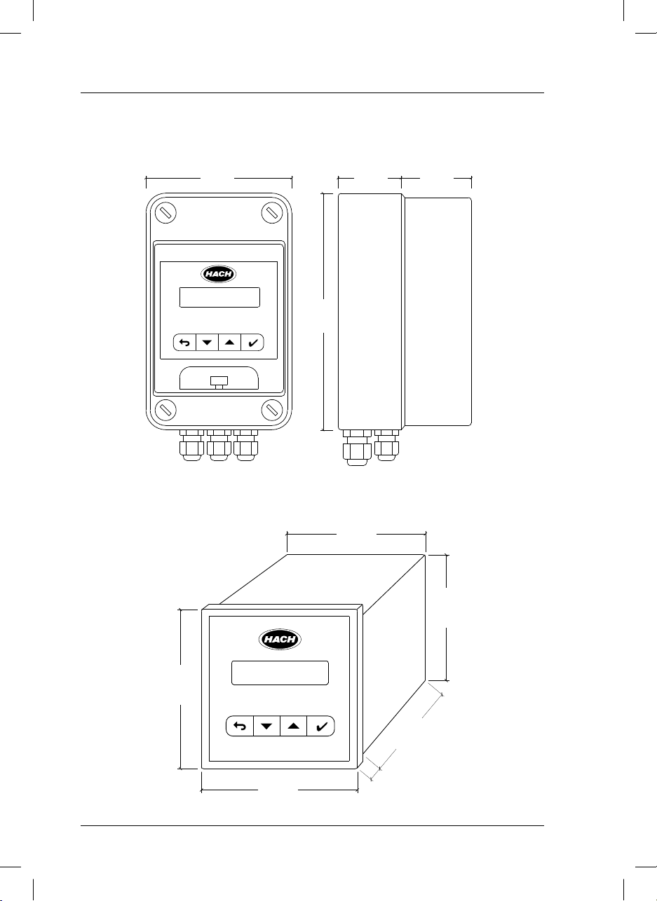
1.1. Dimensions
si629 C (wall mount)
105 mm
4.1 in
6.7 in
170 mm
45 mm
1.8 in
50 mm
2 in
si629 C (panel mount)
90 mm
3.5 in
3.5 in
90 mm
3.8 in
96 mm
80 mm
3.1 in
96 mm
3.8 in
4
si629 C_HACH LANGE_Ed 0510.indd ANG:4si629 C_HACH LANGE_Ed 0510.indd ANG:4 20/5/10 12:06:4820/5/10 12:06:48
7 mm
0.3 in
Page 9
2. General information
As a result of constant improvements to our products sometimes differences may exist between this manual
and the instructions supplied with the instrument.
ENGLISH
2.1. Safety information
Please, read carefully this information before installing and using the instrument !
Pay attention to all danger and caution statements.
2.1.1. Use of hazard information
DANGER
Indicates a potentially or imminently hazardous situation that, if not avoided, will result in death
or serious injury.
WARNING
Indicates a potentially or imminently hazardous situation that, if not avoided, may result in death
or serious injury.
CAUTION
Indicates a potentially hazardous situation that, if not avoided, may result in minor or moderate injury.
Important note
Indicates a situation that, if not avoided, could lead to damage to the instrument. Important information that requires special emphasis.
Note
Information that supplements points in the main text.
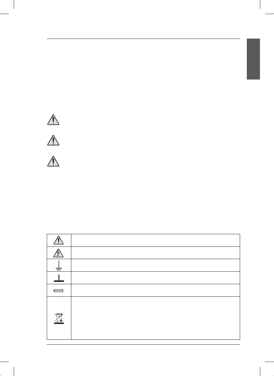
Precautionary labels
Read carefully all labels and tags attached to the instrument.
This symbol references the instruction manual for operation or safety information.
This symbol indicates that a risk of electrical shock or electrocution exists.
This symbol indicates the connection for Protective Earth.
This symbol indicates ground connection.
This symbol identifies a fuse.
Electrical equipment marked with this symbol may not be disposed of in European public disposal systems after 12 August of 2005. In conformity with European local and national regulations (EU Directive
2002/96/EC), European electrical equipment users must now return old or end-of life equipment to the
Producer for disposal at no charge to the user.
Note: For return for recycling, please contact the equipment producer or supplier for instructions on how
to return end-of-life equipment, producer-supplied electrical accessories, and all auxiliary items for proper
disposal.
5
si629 C_HACH LANGE_Ed 0510.indd ANG:5si629 C_HACH LANGE_Ed 0510.indd ANG:5 20/5/10 12:06:4820/5/10 12:06:48
Page 10

2. General information
DANGER
• Remember that the voltage across accessible
parts of the open instrument, may be dangerous
to life. Do not open the instrument when it is
connected to the power supply, there are areas
whose voltage could cause death.
• Always disconnect power to the instrument
before it is opened.
• Repair or adjustment of an opened instrument
under voltage shall be carried out only by
a qualified technician who is aware of the
hazards involved.
• Never work in an environment subject to
explosion hazards. The housing of the
instrument is not gas tight.
• The Company will not be responsible for any
physical damage caused by non authorised
work or manipulation.
• It is the responsibility of whoever uses this
instrument to consult and establish appropriate
safety and health practices and determine the
applicability of regulatory limitations prior to use.
• Before connecting the instrument to a power
supply unit, make sure that the mains voltage
lies within the range:
230 or 24 V AC ±10%, 45-65 Hz (standard
version).
115 V AC ±10%, 45-65 Hz (under demand).
Important notes
• Read carefully the manual of the instrument.
• Avoid direct sunlight over the instrument.
• Exclude the following environmental influences:
- vibrations
- atmospheric humidity higher than 80 %
- corrosive gases present
- temperature < 0 °C, or > 50 °C (< 32 °F, or >
122 °F).
- powerful electric and magnetic fields.
• Only use original accessories and spare parts.
• Have the instrument serviced only by the
Company Service.
2.2. General product information
Proper use
The si629 C is used for conductivity, salinity and temperature measurement in food industry, waste water,
in the environment, etc.
2.3. Items supplied
si629 C (wall mount)
• Instrument (with strips for connections).
• User manual.
6
si629 C_HACH LANGE_Ed 0510.indd ANG:6si629 C_HACH LANGE_Ed 0510.indd ANG:6 20/5/10 12:06:4920/5/10 12:06:49
si629 C (panel mount)
• Instrument (with strips for connections).
• Clamps to fix to the panel.
• User manual.
Page 11
3. Installation
3.1. si629 C (wall mount)
DANGER
Only qualified personnel should conduct the tasks described in this section of the manual.
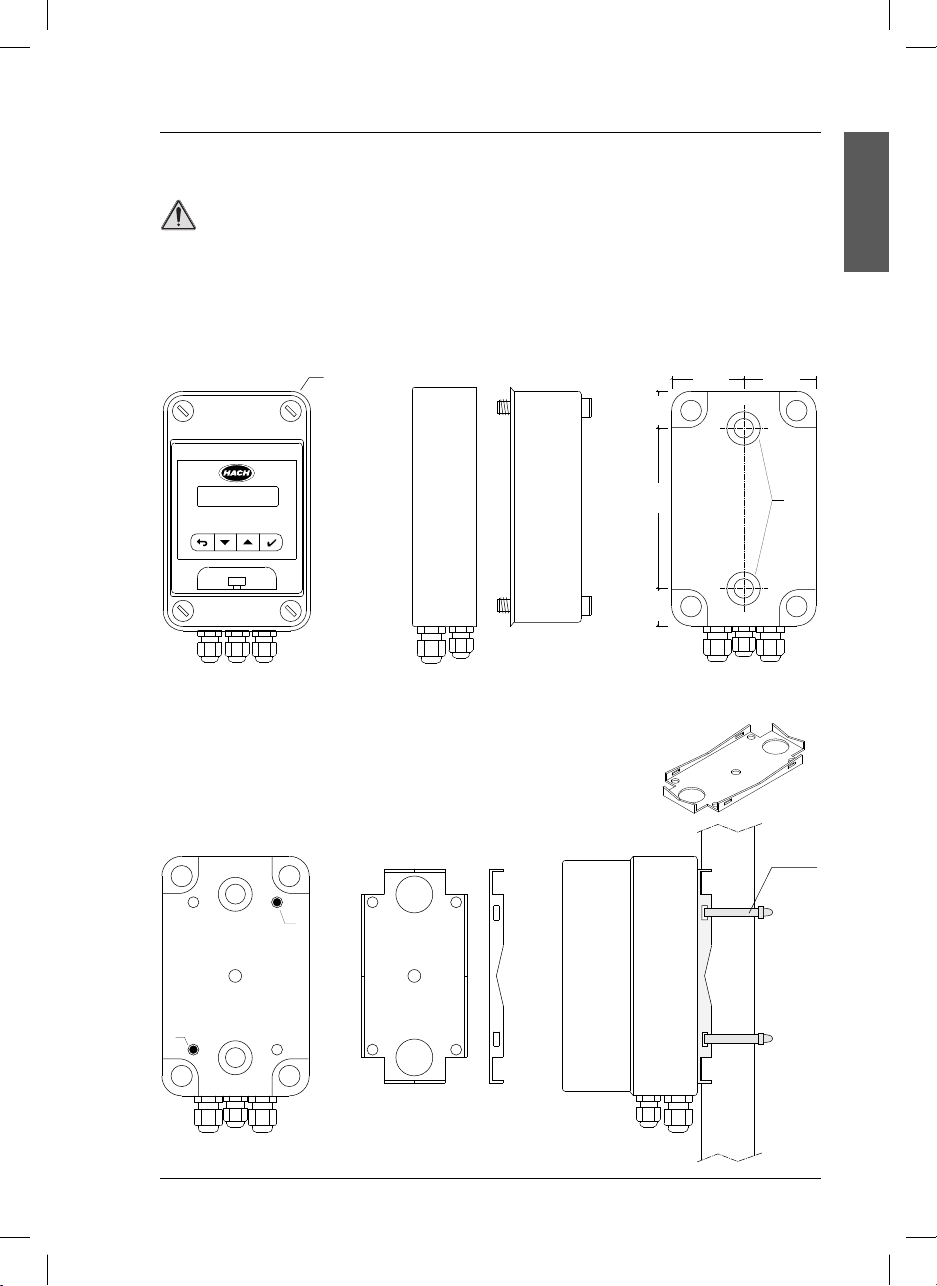
3.1.1. Assembly
Wall mounting
Open the case by unscrewing the 4 A screws.
25 mm
1 in
50 mm
2 in
A
50 mm
2 in
ENGLISH
115 mm
4.5 in
25 mm
1 in
Front view Side view Rear view
For wall mounting of the instruments, use the B drill holes indicated on the scheme.
Pipe or column mounting
Use the pipe adaptor, PN LZU9120.99.
Install the pipe adaptor on the rear part of the instrument using both C drill
holes as indicated on the figure. Fit the unit with two clamps to the column.
C
C
B
Cable
tie
Rear view Pipe adaptor Instrument mounted
7
si629 C_HACH LANGE_Ed 0510.indd ANG:7si629 C_HACH LANGE_Ed 0510.indd ANG:7 20/5/10 12:06:4920/5/10 12:06:49
Page 12
3. Installation
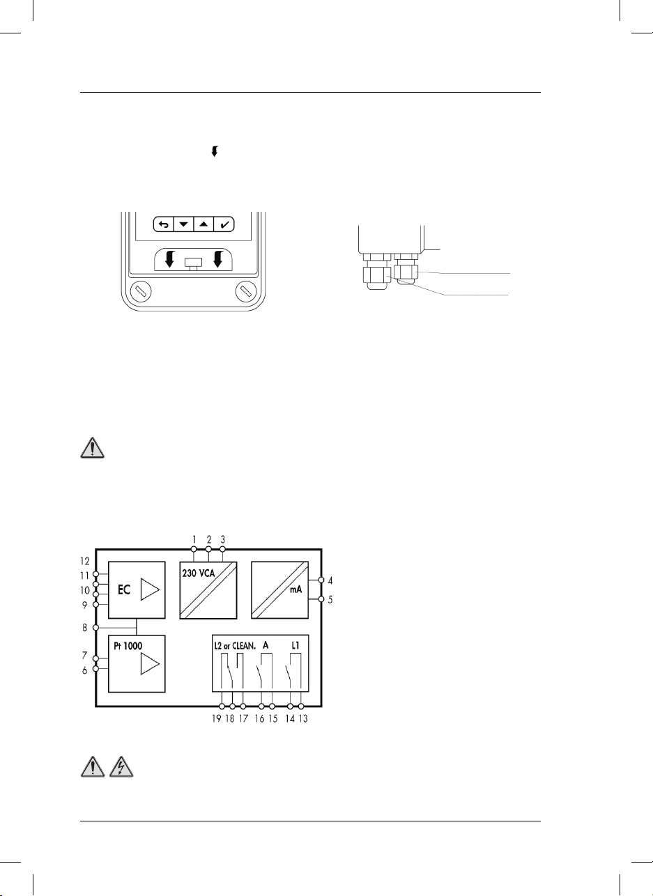
Details
To open the transparent front door, press with two
fingers the part marked with (
) in the scheme.
Cable glands.
On the lower part of the instrument there are 5
cable glands, 2 PG 7 and 3 PG 9.
PG 7 (2 units)
PG 9 (3 units)
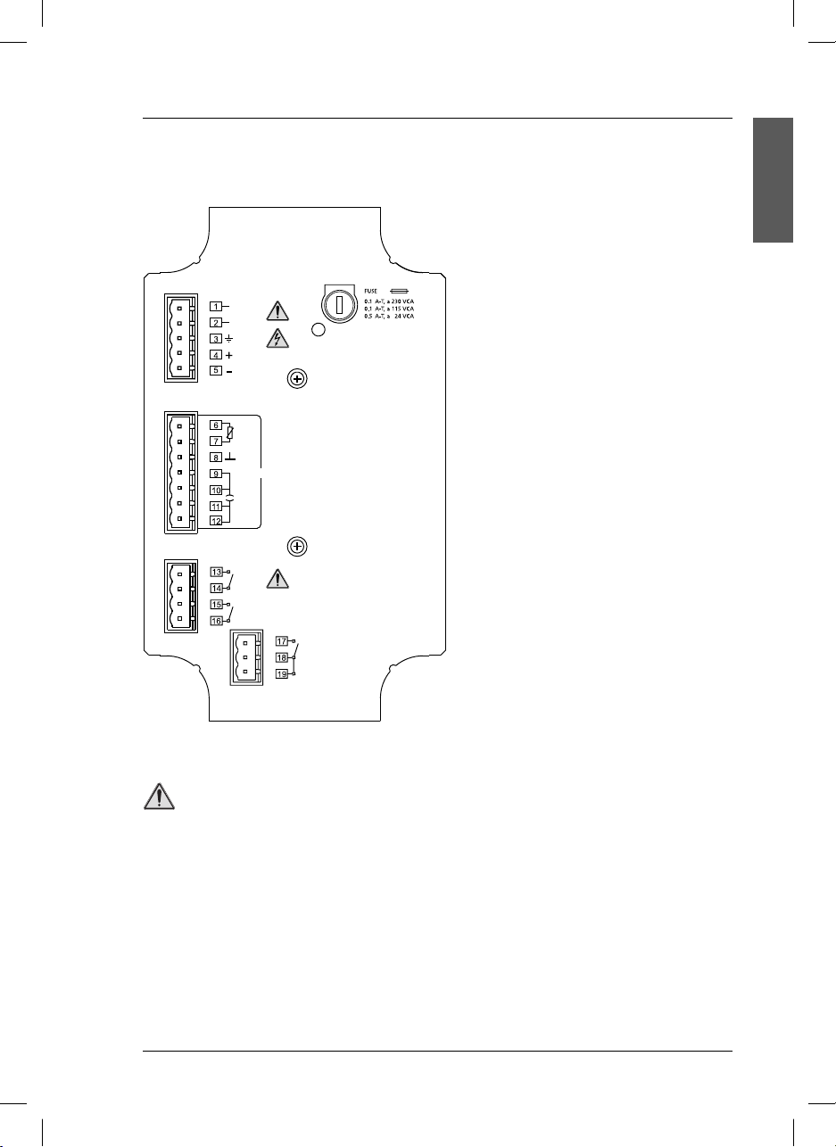
3.1.2. Connections
When making any wiring connections to the instrument, any warnings and notes found throughout the
manual must be adhered to. For more safety information see “Safety information” on page 5.
DANGER
Always disconnect power to the instrument when making any electrical connections.
System functions
1,2 Voltage 230 or 24 VCA ± 10%.
(115 VCA upon request).
3 Ground connections, see
notes (
page 9).
4,5 Current output 4-20 mA (EC).
6,7 Input for temperature probe.
8 Cell cable shielding
9 to 12 Entrada para célula de 2 polos.
13,14 Limit 1 relay contacts.
15,16 Alarm relay contacts.
17 to 19 Limit 2 or Cleaning relay contacts.
DANGER
High-voltage wiring for the instrument is protected by a protective casing. The protective casing
Important
must remain in place unless a qualified installation technician is installing wiring for power.
8
si629 C_HACH LANGE_Ed 0510.indd ANG:8si629 C_HACH LANGE_Ed 0510.indd ANG:8 20/5/10 12:06:5020/5/10 12:06:50
Page 13
3. Installation
Terminal assignment (interior panel)
Important notes:
• El si629 C does not require ground conection (3 or 4 terminals).
• In environnements with interference prob-
VCA
WHEN IT IS ON, IT INDICATES A FUSED FUSE.
4-20 mA
Pt 1000
CELL
L 1
A
lems it is recommended to connect the instrument to ground in terminal 3.
If ground connection is not available, it is
recommended to leave terminal 3 free and
connect the additional shield of the triaxial
cable to the terminal 8 (Pt 1000 shielding).
ENGLISH
L 2 / C
DANGER
Relays:
- Limit the current up to 3 A by using one fuse.
- Do not connect cables with voltage higher than 24 V.
9
si629 C_HACH LANGE_Ed 0510.indd ANG:9si629 C_HACH LANGE_Ed 0510.indd ANG:9 20/5/10 12:06:5020/5/10 12:06:50
Page 14
3. Installation
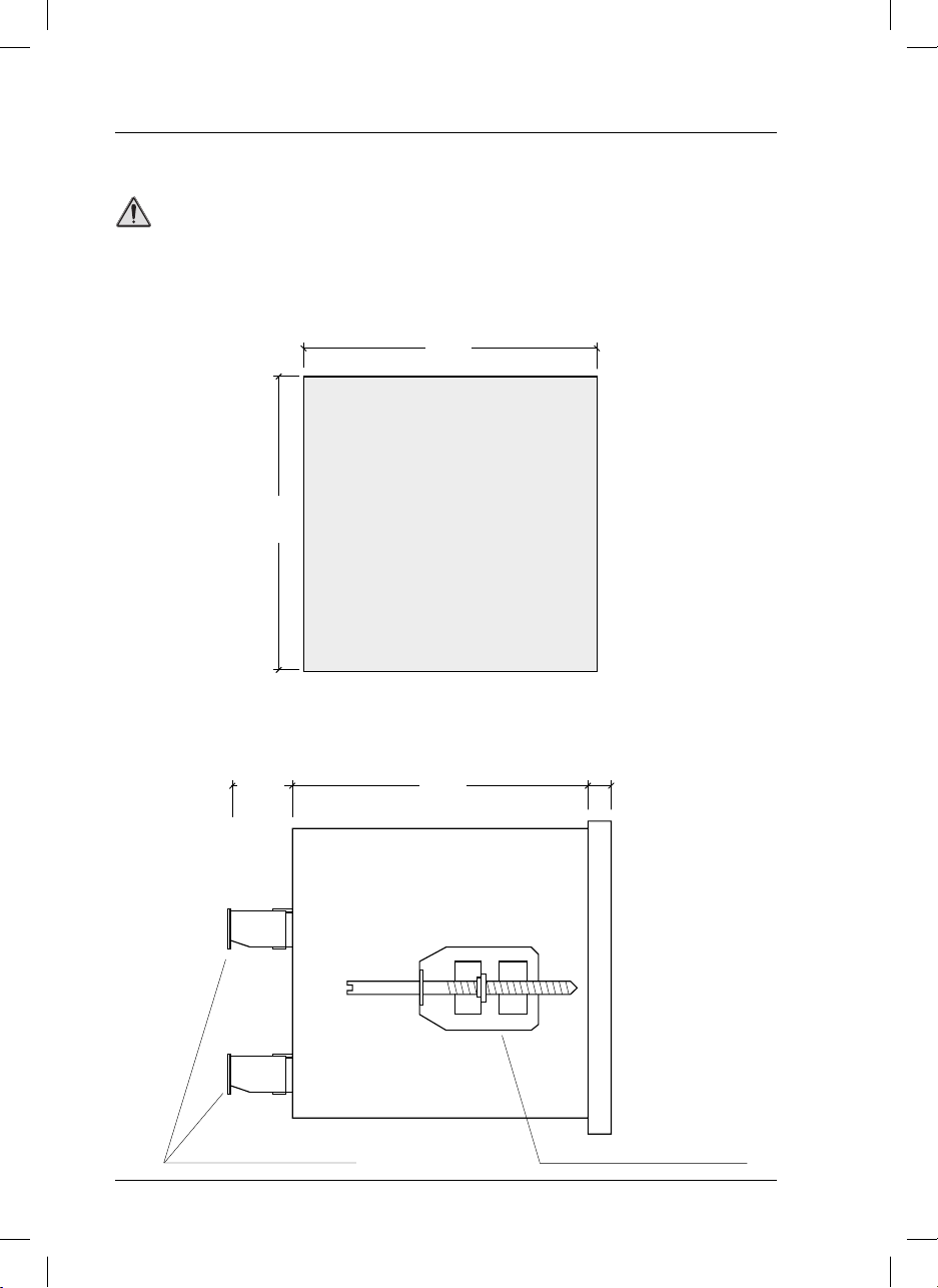
3.2. si629 C (panel mount)
DANGER
Only qualified personnel should conduct the tasks described in this section of the manual.
3.2.1. Assembly
For the si629 C mounting a drill hole is required according to the diagram.
92 mm
3.7 in
3.7 in
92 mm
Panel
After putting the instrument in the panel, it must be fitted using two clamps as indicated in the figure.
Drill hole
21 mm
0.8 in
80 mm
3.1 in
7 mm
0.3 in
Plug-in screw connector Clamp to fix to the panel
10
si629 C_HACH LANGE_Ed 0510.indd ANG:10si629 C_HACH LANGE_Ed 0510.indd ANG:10 20/5/10 12:06:5120/5/10 12:06:51
Side view
Page 15
3. Installation
When making any wiring connections to the instrument, any warnings and notes found throughout the
manual must be adhered to. For more safety information see “Safety information” on page 5.
DANGER
Always disconnect power to the instrument when making any electrical connections.
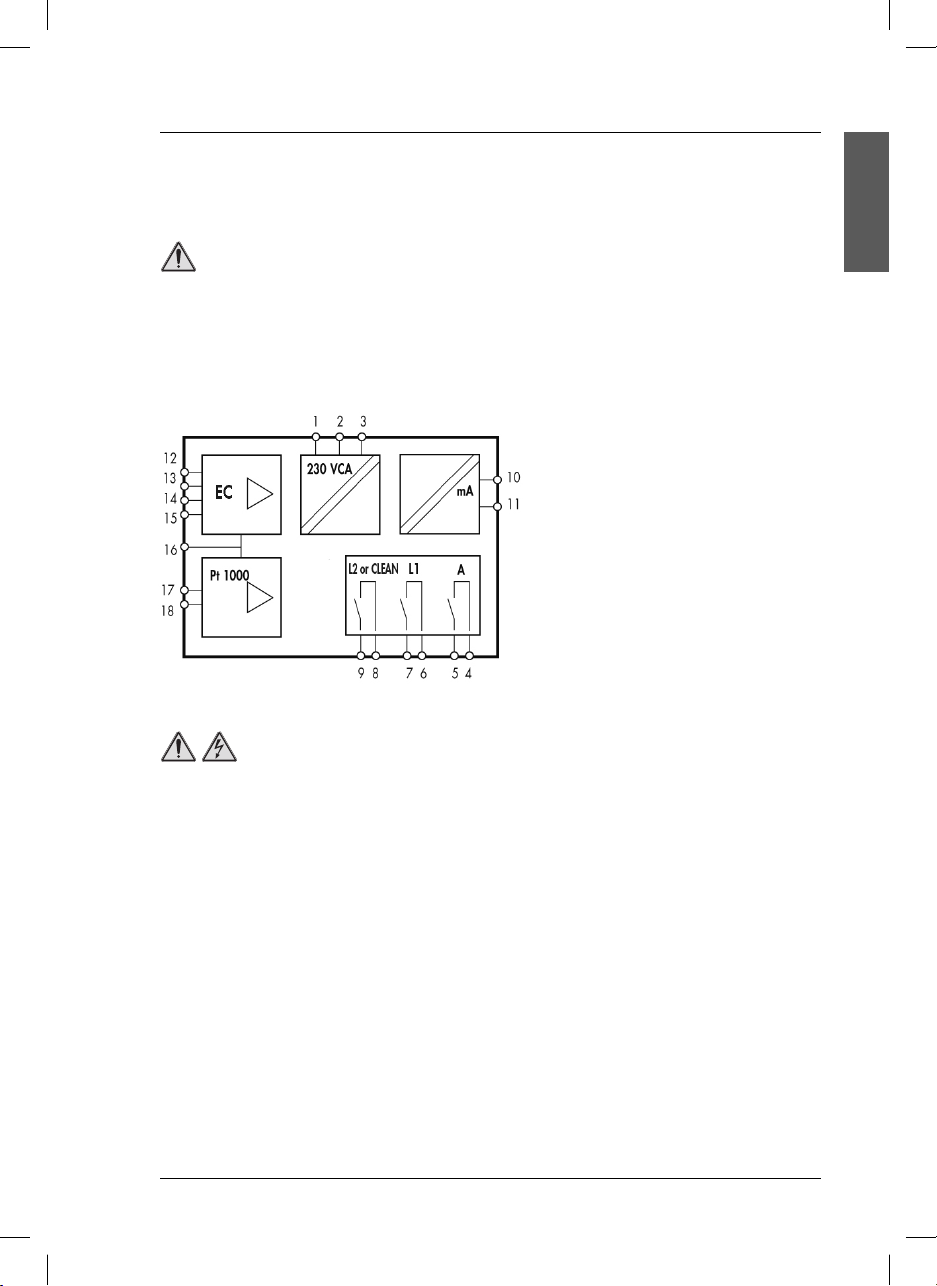
3.2.2. Connections
System functions
1 Ground connection, see Important
notes (page 12).
2,3 Power supply 230 or 24 VCA ± 10%.
(115 VCA upon request).
4,5 Alarm relay contacts.
6,7 Limit 1 relay contacts.
8,9 Limit 2 or Cleaning relay contacts.
10,11 Current output 4-20 mA (EC).
12 to 15 Input for 2 pole cell.
16 Cell cable shielding.
17,18 Input for temperature probe.
DANGER
High-voltage wiring for the instrument is protected by a protective casing. The protective casing
must remain in place unless a qualified installation technician is installing wiring for power.
ENGLISH
11
si629 C_HACH LANGE_Ed 0510.indd ANG:11si629 C_HACH LANGE_Ed 0510.indd ANG:11 20/5/10 12:06:5120/5/10 12:06:51
Page 16
3. Installation
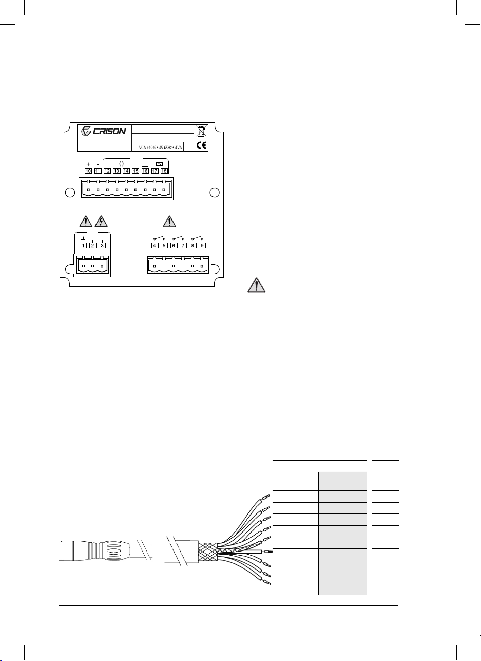
Terminal assignment (rear panel)
Important notes:
• El si629 C
does not require ground
connection (terminal 1).
• In environnements with interference problems
CRISON INSTRUMENTS, S.A.
E-08328 ALELLA - Barcelona
Made in Spain
Transmitter si629 C
S/N:
IP 54
CELL4-20 mA
it is recommended to connect the instrument to
ground using terminal 1.
It is also recommended to use shield cables
for the cell signal (triaxial cable), and the
temperature probe.
The external shield of the triaxial cable and
the temperature cable must be connected to
RED
VCA
A
L 2 / C
L
terminal 16.
DANGER
Relays:
- Limit the current up to 3 A by using
one fuse.
- Do not connect cables with voltage
higher than 24 V.
3.3. Cell cables
Compensation of the cable length
To minimize the effect of the cable resistance in a conductivity measurement, the cable length is compensated by the 4-wire system. With the Pt 1000 temperature sensor, the cable resistance has little importance.
However, in order to reduce the resistance of the conductor to a half, 2 cables have been connected to
the ends of the sensor.
3.3.1. Cells with MP-5 connector
TERMINALS
MP-5 connector, 5 contacts
si629 C
(wall mount)
618 White
618 Brown
717 Pink
7 17 Yellow
816 Shield
915 Green
10 14 Blue
11 13 Gray
12 12 Red
si629 C
(panel mount)
12
si629 C_HACH LANGE_Ed 0510.indd ANG:12si629 C_HACH LANGE_Ed 0510.indd ANG:12 20/5/10 12:06:5120/5/10 12:06:51
COLOUR
Page 17
3. Installation
3.3.2. Cells with connector S8
TERMINALS
si629 C
(wall mount)
9 12 Middle
10 13 Middle
11 14 Shield
12 15 Shield
si629 C
(panel mount)
COLOUR
ENGLISH
Important note:
Fit a jumper between terminals 9 and 10 (12 and 13 in panel mount instrument) and another between
the terminals 11 and 12 (14 and 15 in panel mount instrument).
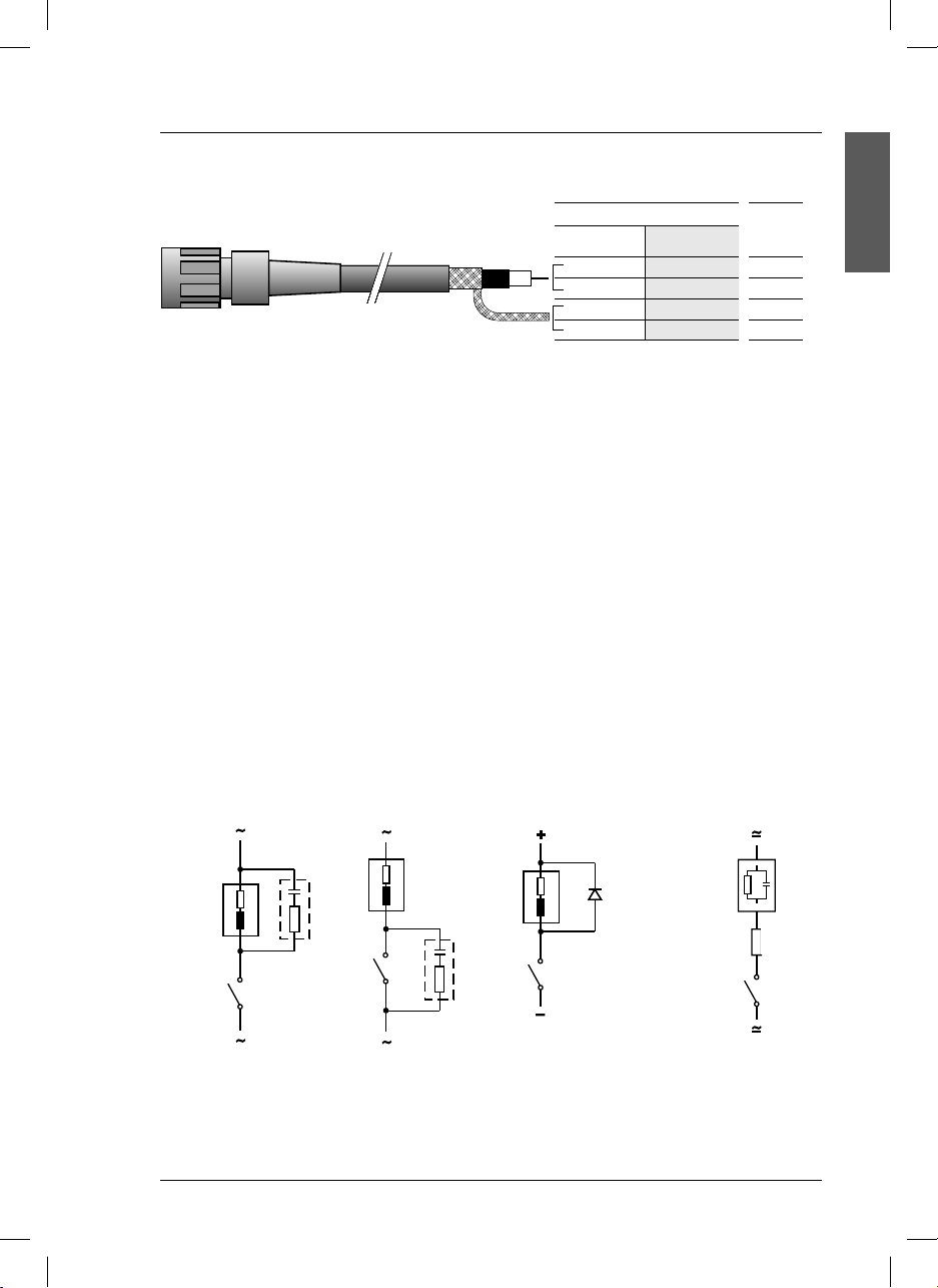
3.4. Protective wiring of switching contacts
Relay contacts are subjected to electrical erosion.
Especially with inductive and capacitive loads, the service life of the contacts will be reduced.
For suppression of sparks and arcing, components such as RC combinations, nonlinear resistors, series
resistors and diodes should be used.
Typical protective wirings
AC applications with inductive load
DC applications with
inductive load
AC/DC with
capacitive load
RC
Load
RC
Contact
relay
Typical RC at 230 VAC: Capacitor 0.1 µF/630 V
Resistor 100 Ω/1 W
Diode
1N4007
Maximum relays load: AC < 24 V / < 3 A / < 72 VA.
si629 C_HACH LANGE_Ed 0510.indd ANG:13si629 C_HACH LANGE_Ed 0510.indd ANG:13 20/5/10 12:06:5120/5/10 12:06:51
Load
R
R, for example:
5 Ω / 1 W at
24 V / 0.4 A
13
Page 18
4. Operation
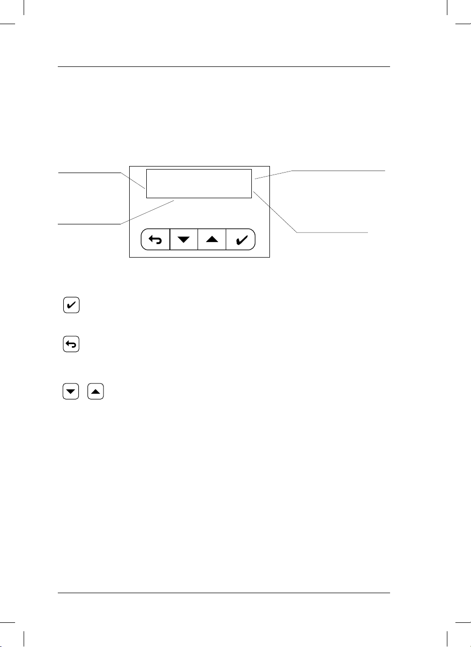
4.1. Description
Display
si629 C have an alphanumeric display that explains itself. One of the most significant screens is described below as an example:
Measured value.
MEASURING 21.3 °C
10.9µS/cm @ 25 °C
Sample temperature
Resolution:
1 °C manual selection.
0.1 °C measuring with Pt 1000
Measuring units.
Keys
Reference temperature
25 or 20 °C
ENTER.
• Horizontal movements to move forward in the “diagram”.
• Acceptance of numerical values.
ESCAPE.
• Horizontal movements to move back in the “diagram”.
• Vertical movements to move back in the “diagram”.
• To erase numerical values.
• Modification of numerical values.
• Cursor “>” movements on the screen.
14
si629 C_HACH LANGE_Ed 0510.indd ANG:14si629 C_HACH LANGE_Ed 0510.indd ANG:14 20/5/10 12:06:5220/5/10 12:06:52
Page 19
4. Operation
4.2. Setting up
Connect the si629 C to mains. At power up the first time only the following screens will appear:
ENGLISH
si629_C
V1.0
IDIOMA >Español
Italiano
Possibility to select other
language with keys.
Français
English
MEASURE
MEASURING 22.3°C
µS/cm
545
@25°
Deutsch
Português
The instrument is already measuring conductivity, with the following factory settings:
• Temperature coefficient 2% / °C.
• Cell constant C=1 cm
-1
.
• Reference temperature, RT, at 25°C.
• Relay 1, limit activated at 1000 µS/cm, and deactivated at 800 µS/cm (measuring salinity, activated
at 1 mg/l and deactivated at 0.8 mg/l).
• Relay 2, cleaning during 3 sec each hour, with 5 sec of post-cleaning time.
• Alarm relay, activation after 10 min of reading out of limits.
• Current output 4 mA = 200 µS/cm, 20 mA = 2000 µS/cm (measuring salinity
4 mA = 0.2 mg/l, 20 mA = 2 mg/l).
• Current output with the instrument in “Hold” mode, 21mA.
• Data Logger deactivated.
To modify this configuration see page 17.
15
si629 C_HACH LANGE_Ed 0510.indd ANG:15si629 C_HACH LANGE_Ed 0510.indd ANG:15 20/5/10 12:06:5320/5/10 12:06:53
Page 20
4. Operation
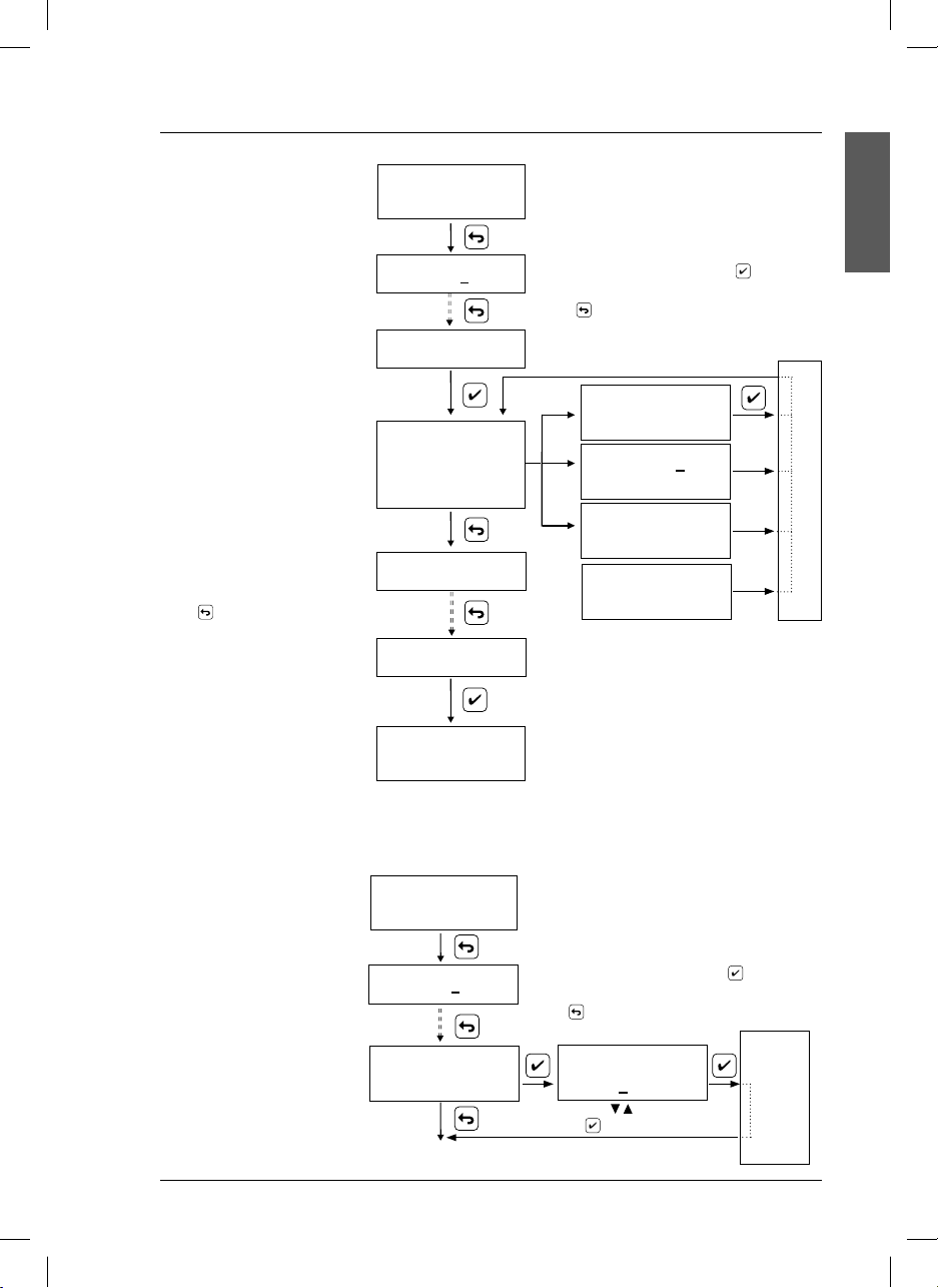
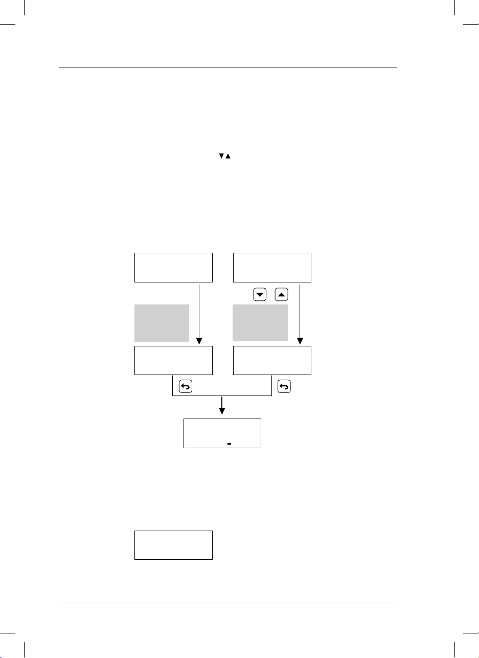
4.3. Quick guide
This page shows the instrument’s operation by blocks. It is intended to provide a quick idea about all the
instrument’s capabilities and how to gain access to them.
MEASURING 22.3°C
µS/cm
545
@25°
Security acces
code.
It limits the access
to calibration
or programming
of the instrument
CODE 000
Vary the underlined digit with
and accept with .
Authorised code = 100
by non authorised
personnel.
When the “Code” screen has been shown
for more than 30 sec. the instrument will
automatically return to MEASURE.
Instrument in “Hold” state
When being in the gray zone, the instrument is in hold state:
• Limit and cleaning relays are open.
(Alarm OFF).
• According to the configuration the current output is frozen at 21 mA or at the
mA corresponding to the last measured
value.
(*) When being in Test 4-20 the current is
the one programmed manually to be able
to carry out the test.
To quit the hold state it is necessary to return to Measure. The Current output 4-20
and the Relays will activate in 10 sec.
MEASURE
CALIBRATE
CELL
CONFIGURATION
LIMITS
ALARM
CLEANING
OUTPUT 4 to 20 mA
HOLD
LANGUAGE
MANUAL RELAY
TEST 4 to 20 mA
DATA LOGGER
See “Calibration“
(page 18)
See “Configuration“
(page 17)
See “Programming ...”
(page 20-21)
See “Manual control
of relays
(page 24)
See “Test 4-20 mA“
(page 24) (*)
See “Data logger““
(page 25) (*)
16
si629 C_HACH LANGE_Ed 0510.indd ANG:16si629 C_HACH LANGE_Ed 0510.indd ANG:16 20/5/10 12:06:5320/5/10 12:06:53
Page 21
4. Operation
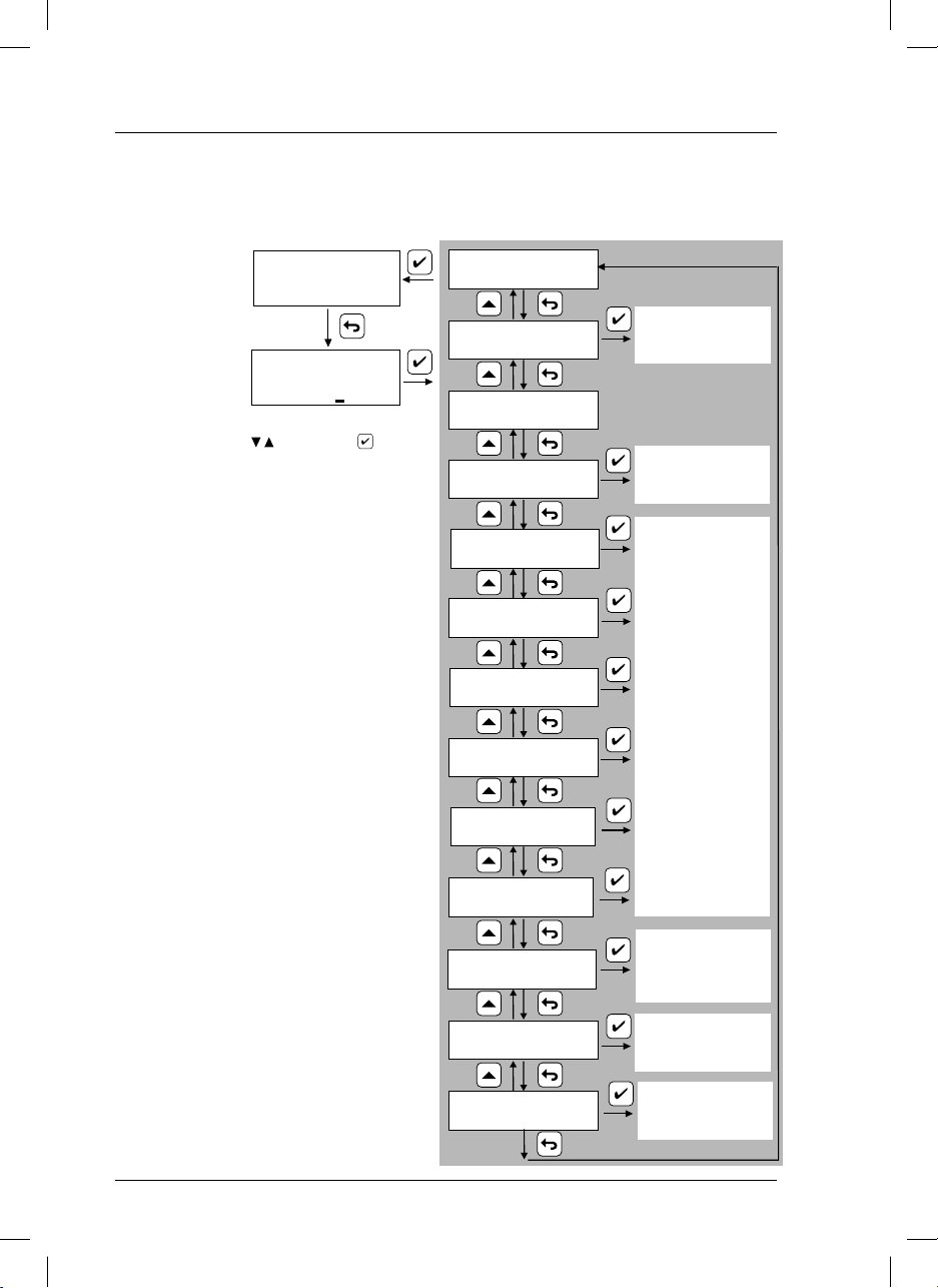
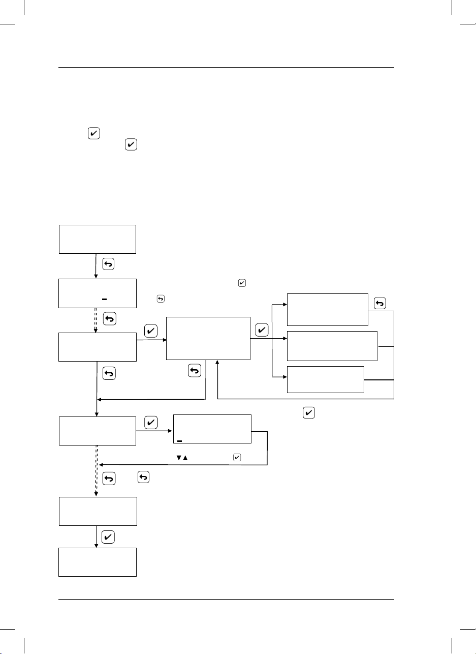
4.4. Configuration
Follow the diagram for
MEASURING 22.3°C
545µS/cm @25°C
modifying the configuration.
CODE 000
CONFIGURE
Conf. > Ref. Temp.
T.C.
Relay 2
Type measurement
Press until the display MEASURE is reached.
MEASURING 22.3°C
545µS/cm @25°C
LIMITS
MEASURE
Enter code 100 and y accept with
Press until the desired option is reached.
Ref. Temp. > 25 °C
20 °C
T.C. 2.00%
Relay 2 > Cleaning
Limit 2
STORING DATA
> Conductivity (*)
Salinity
Note: During Configuration the instrument is in
Hold state:
• Limit and cleaning relays contact are open.
(Alarm OFF).
• Current output is frozen at the value programmed in Hold.
To quit the Hold state it is necessary to return
to Measure. The Current output 4-20 and the
Relays will activate in 10
ENGLISH
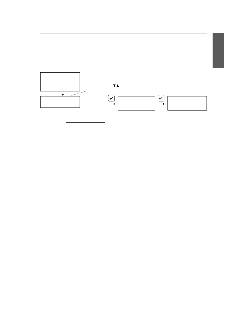
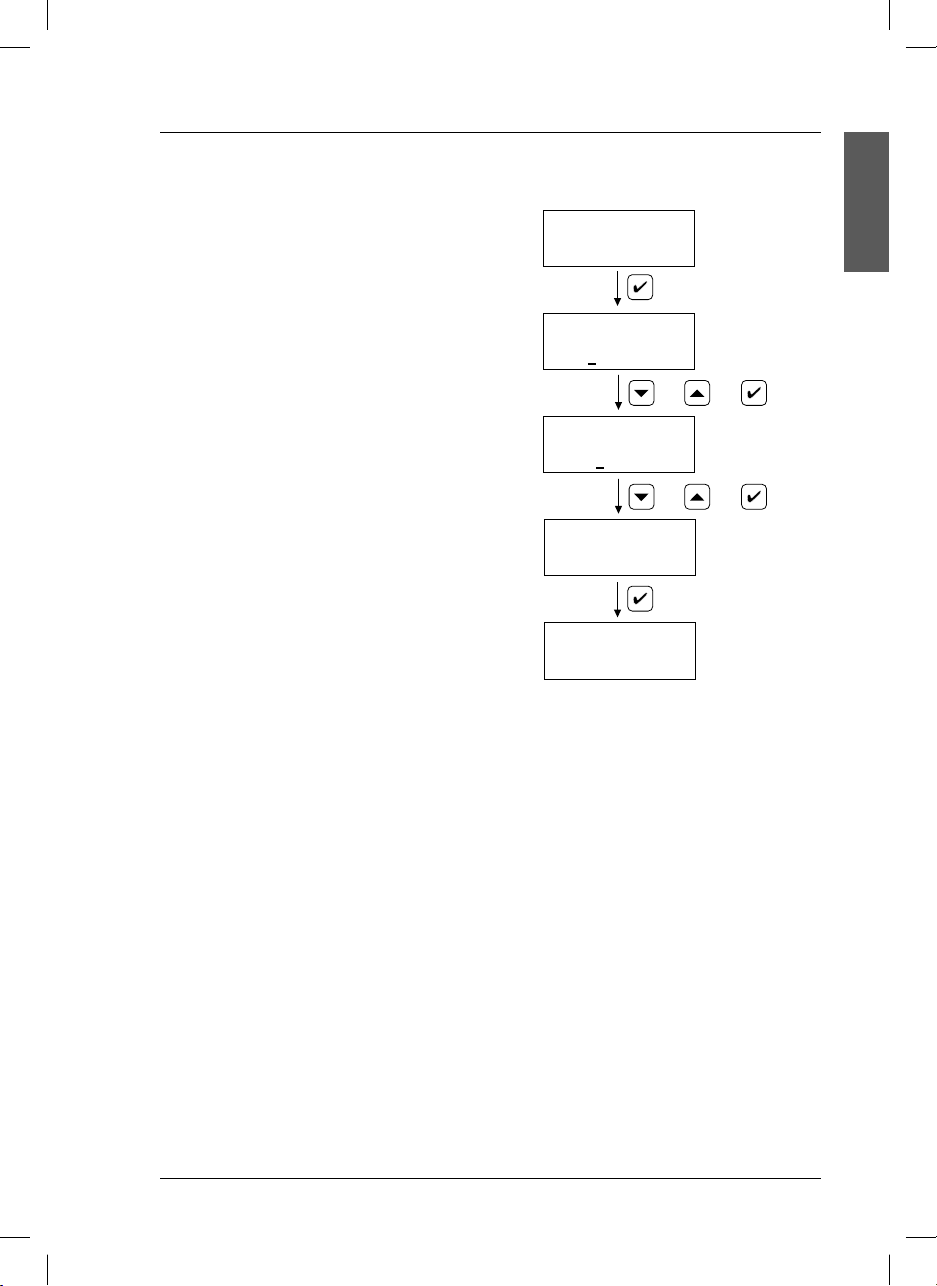
4.5. Cell constant selection
Select the constant cell before
modifying the configuration.
Select the nominal value of the
cell in use. If the exact value
is known, introduce it and no
need to calibrate.
si629 C_HACH LANGE_Ed 0510.indd ANG:17si629 C_HACH LANGE_Ed 0510.indd ANG:17 20/5/10 12:06:5420/5/10 12:06:54
MEASURING 22.3°C
545µS/cm @25°C
CODE 000
Enter code 100 and y accept with
Press until the desired option is reached.
CELL
CELL
-1
1.000 cm
Vary with and accept
with
DATA
STORING
17
Page 22
4. Operation
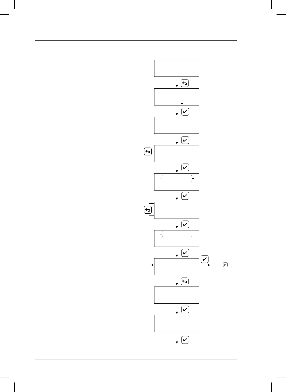
4.6. Calibration
This process involves adjusting the read values by a
conductivity measuring system (instrument and cell) according to the values of standard solutions.
Calibration is very important for highly accurate readings.
The equipment is capable of one-, two- and three-point
calibration, and automatically recognises 147µS/cm,
1413 µS/cm and 12.88 mS/cm standards.
The calibration parameters are stored in the memory
until a new calibration is performed.
MEASURING 22.3°C
545
µS/cm
@25°
CODE 000
Introduce the
code 100.
One-point calibration
This form of calibration is acceptable when measuring
conductivity values around that of the used standard.
This is the most common type of calibration. In this type,
1413 µS/cm is the most commonly-used standard.
23.2°C
Standard 147 µS/cm
Two-point calibration
This type of calibration is recommended for work in high
or low conductivity regions where accuracy is required.
The 147µS/cm and 1413 µS/cm standards should be
used for low conductivity regions, and 1413 µS/cm and
12.88 mS/cm for high conductivity measurements.
Three-point calibration
Standard 1413 µS/cm
This type of calibration is recommended when the conductivity of the samples to be measured ranges from
low to high.
Notes:
When a calibration in 2 or 3 points is performed, start
with the standard with lowest conductivity. In this way, a
contamination is avoided.
During Calibration the instrument is in Hold state:
• Limit and cleaning relays contact are open.(Alarm OFF).
• Current output is frozen at the programmed value in
Hold.
To quit the Hold state it is necessary to return to MEASURE.
The Current output 4-20 and the Relays will activate in
10 sec.
For practical reasons, in calibration is recommended
to select the temperature manually even if you have
connected a CAT probe (Pt 1000/Pt 100).
23.2°C
Standard 12.88 mS/cm
P1=147,0 µS/cm
C
P2=1413,0 µS/cm
C
CALIBRATE
CAL. 23.2°C
142.6 µS/cm
23.2°C
CAL. 23.2°C
1364 µS/cm
=0,393 cm
1
=0,397 cm
2
-1
-1
to MEASURE
If you have a
cell without CAT,
manually enter the
temperature value.
Once the reading
is stable, the
display changes
automatically.
Press to
perform 3 point
calibration.
18
si629 C_HACH LANGE_Ed 0510.indd ANG:18si629 C_HACH LANGE_Ed 0510.indd ANG:18 20/5/10 12:06:5520/5/10 12:06:55
Page 23

4. Operation
4.6.1. Recognized standards
Table of values according to temperature.
Values stored in the si629 C.
°C µS/cm µS/cm mS/cm
15.0 119 1147 10.48
16.0 122 1173 10.72
17.0 125 1199 10.95
18.0 127 1225 11.19
19.0 130 1251 11.43
20.0 133 1278 11.67
21.0 136 1305 11.91
22.0 139 1332 12.15
23.0 142 1359 12.39
24.0 145 1386 12.64
25.0 147 1413 12.88
26.0 150 1440 13.13
27.0 153 1467 13.37
28.0 156 1494 13.62
29.0 159 1522 13.87
30.0 162 1549 14.12
ENGLISH
19
si629 C_HACH LANGE_Ed 0510.indd ANG:19si629 C_HACH LANGE_Ed 0510.indd ANG:19 20/5/10 12:06:5620/5/10 12:06:56
Page 24
4. Operation
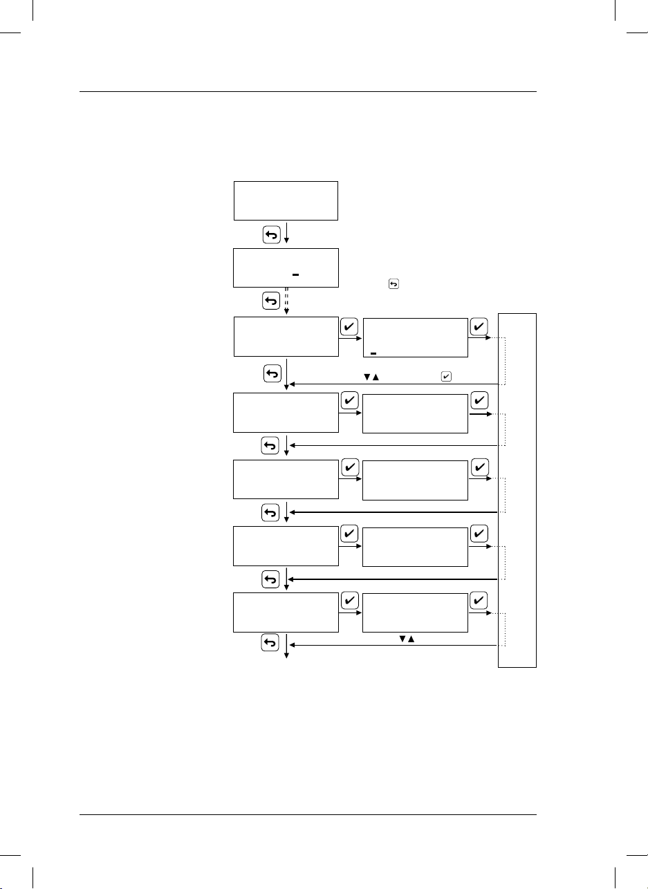
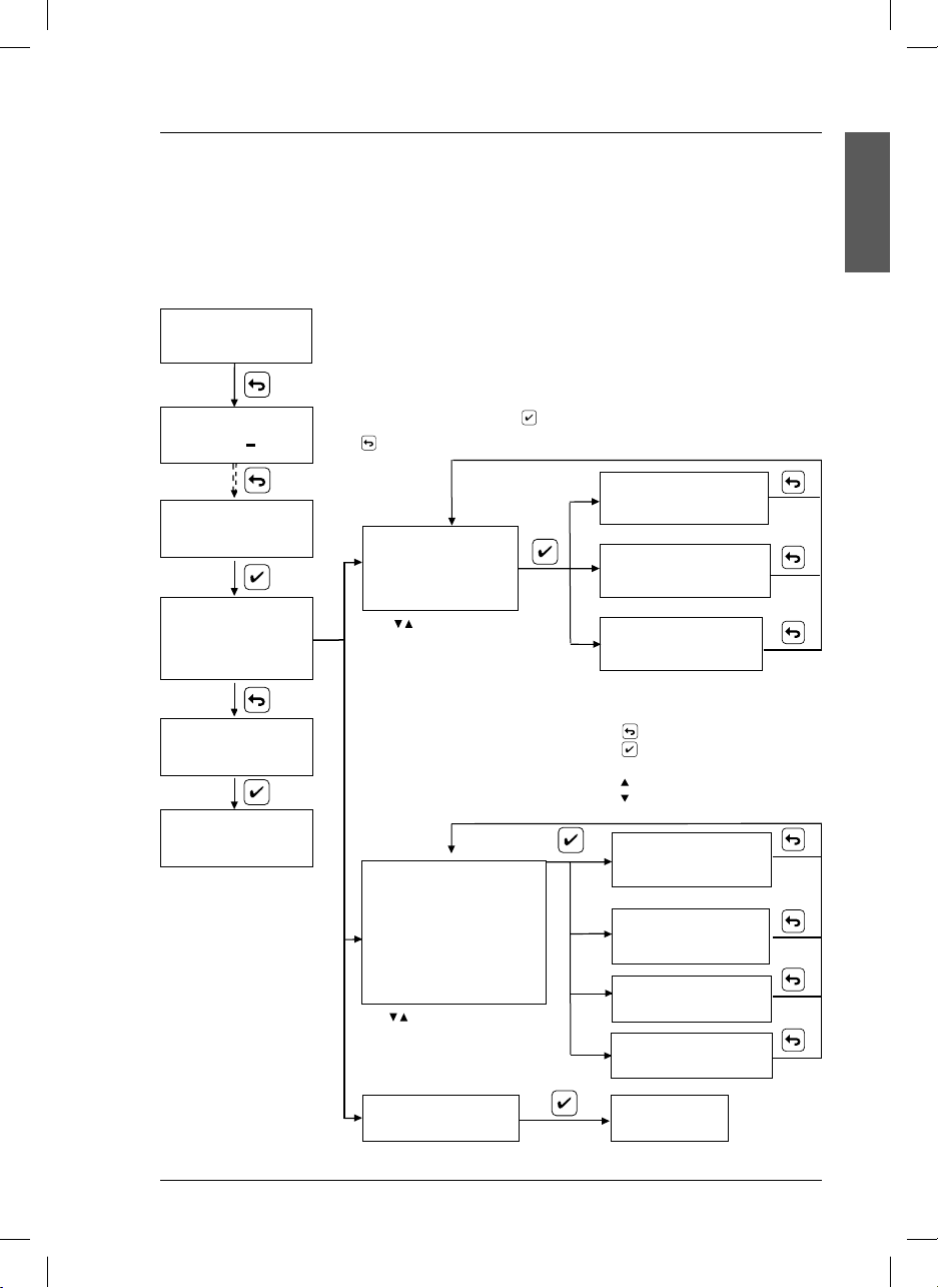
4.7. Programing
The instrument is supplied with the default configuration specified in Start-up, page 15.
To modify the default configuration and adapt it to specific applications follow the diagram below.
Limit.
Select the relay values.
Input “ON” (closed contact).
Output “OFF” (open contact).
Conductivity: between 0.0 µS &
200 mS.
Salinity: between 0.0 mg/l &
278 g/l
* LIMIT 2 / CLEANING
The option LIMIT 2 will only appear
if relay 2 is configured as a limit
relay.
Alarm
Selection of the time lag before
activating the alarm. Select between
1 and 99 seconds, minutes or hours.
0=deactivated.
Cleaning
T on: cleaning time. Min. value: 3
sec. (relay activated or cleaning).
To deactivate the cleaning function,
T on=0 must be programmed.
Toff: Cleaning deactivation time.
Min. value: 3 s (relay deactivated ).
Example: Ton: 3 sec., Toff: 1 h; it
will clean during 3 sec. each hour.
Post-cleaning time: 0 to 99 sec.
Output current.
Select de conductivity values
corresponding to the current output
(4 mA and 20 mA).
Conductivity: between 0.0 µS
& 200 mS.
Salinity: between 0.0 mg/l &
278 g/l t
Hold. Selection of the current output
when the instrument is in Hold
state: fixed at 21 mA or at the mA
corresponding to the last measured
value.
MEASURING 22.3°C
545
4 to 20 mA OUTPUT(*)
µS/cm
@25°
CODE 000
LLIMIT (*)
ALARM
CLEANING
HOLD
Continue at
the next page.
Enter code 100
Press until the desired option is reached.
ON - - - - - - OFF
1000 µS 800 µS
Vary the underligned digit with
and accept with
ALARM
01 min
CLEANING
Ton= 03 s Toff=01 h
4 mA 20 mA
STORING DATA
200 µS 2.0 mS
> 21 mA
last value
Vary with
(*) LIMIT and 4 - 20 mA OUTPUT: Allow the introduction of 5 digits. Place the decimal on the desired point.
20
si629 C_HACH LANGE_Ed 0510.indd ANG:20si629 C_HACH LANGE_Ed 0510.indd ANG:20 20/5/10 12:06:5620/5/10 12:06:56
Page 25
4. Operation
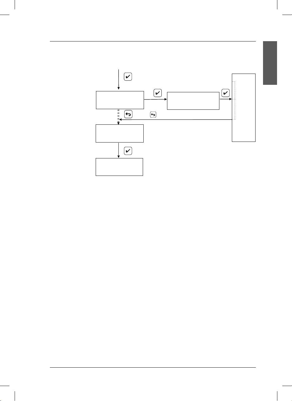
4.7. Programming (continuation)
ENGLISH
Language. Select the
language among
English, German,
Spanish, French,
Italian, Portuguese.
LANGUAGE
Italian
Press until MEASURE is reached.
MEASURE
MEASURING 22.3°C
µS/cm
545
Notas: During Programming the instrument is in Hold state:
• Limit and cleaning contact relays are open. (Alarm OFF).
• Current output is frozen at the value programmed in
Hold.
To quit the Hold state it is necessary to return to MEASURE.
The Current output 4-20 and the Relays will activate in
10 sec.
@25°
LANGUAGE > Spanish
STORING DATA
21
si629 C_HACH LANGE_Ed 0510.indd ANG:21si629 C_HACH LANGE_Ed 0510.indd ANG:21 20/5/10 12:06:5720/5/10 12:06:57
Page 26
4. Operation
4.8. Measure
Conductivity, salinity and temperature measurement
The value of the specific conductivity or salinity, the sample temperature in °C and the reference temperature appear simultaneously on the display.
If the Pt 1000 temperature probe is not connected it is necessary to inform the instrument about the
temperature of the solution using the arrow keys
Conductivity cells incorporate a Pt 1000 temperature sensor.
Conductivity measurement
.
... with Pt 1000 probe
MEASURING 22.3°C
µS/cm
545
Temperature
measured
automatically
MEASURING 22.3°C
µS/cm
545
Salinity measurement
... with Pt 1000 probe
@25°
@25°
... without Pt 1000 probe
MEASURING 25°C
545
MEASURING 22°C
565
CODE 000
µS/cm
@25°
Manually
entered
temperature
µS/cm
@25°
MEASURING 22.3°C
117.7 mg/l
22
si629 C_HACH LANGE_Ed 0510.indd ANG:22si629 C_HACH LANGE_Ed 0510.indd ANG:22 20/5/10 12:06:5720/5/10 12:06:57
Page 27
4. Operation
4.9. Conductivity readjustment
The si629 C allows readjusting the conductivity measured
value by modifying the reading that appears on the display. Previously the conductivity of the sample must have
been measured with a perfectly calibrated instrument.
During the readjustment the si629 C behaves as it was
calibrated with one buffer only.
Every time the si629 C is calibrated in the conventional
manner, the readjustment is lost.
MEASURING 18.3°C
12.15
INDIRECT CAL.
12.15 mS
INDIRECT CAL.
12.15 mS
P: 12.28mS
C: 0.700 cm
MEASURING 18.3°C
12.28
mS/cm
mS/cm
@25°
Press for more than 3 sec.
or
+
or
+
-1
@25
ENGLISH
Important: It is not possible to perform salinity readjustment.
23
si629 C_HACH LANGE_Ed 0510.indd ANG:23si629 C_HACH LANGE_Ed 0510.indd ANG:23 20/5/10 12:06:5720/5/10 12:06:57
Page 28
4. Operation
4.10. Manual control of relays and test 4-20 mA
To verify the correct functioning of the relays and 4 to 20 output, enter the options:
Manual Relay
Pressing
When releasing the
Test 4 to 20 mA
Select in the display, the µS/cm or mg/l value desired to simulate. The current output must be the
indicated in the display, according to the selected values in Programming Output 4 to 20, see page
20-21.
MEASURING 22.3°C
545
the selected relay is activated (except the alarm relay, which is deactivated).
µS/cm
@25°
CODE 000
key the selected relay is deactivated.
Enter code 100 and y accept with
Press until the desired option is reached.
RELAY LIMIT OFF
545 µS
25.0°C
MAN. R. > LIMIT 1
MAN. RELAY
CLEANING/LIMIT 2
ALARM
CLEANING R./LIMIT 2 O F F
545 µS
25.0°C
ALARM
545 µS
Press
o activate any of the relays
TEST 4-20 mA
Press up to return
to MEASURE
200 µS
Vary the underligned digit with
and accept with
MEASURE
MEASURING 22.3°C
µS/cm
Io (4 to 20) =4.00 mA
545
24
si629 C_HACH LANGE_Ed 0510.indd ANG:24si629 C_HACH LANGE_Ed 0510.indd ANG:24 20/5/10 12:06:5720/5/10 12:06:57
@25°
(ON). When not pressing ENT anymore, it
deactivates (OFF).
Nota: During Manual control of relays
and Test 4 to 20 the instrument is in
Hold state:
• Limit and cleaning contact relays are
open. (Alarm OFF).
• Current output is frozen at the value
programmed in Hold, except the
option “Test 4-20” that maintains
the manually programmed current
output for carrying out the tests.
To quit the hold state it is necessary to
return to MEASURE.
OFF
25.0°C
Page 29
4. Operation
4.11. Data Logger
The si629 C is able to store up to 200 data in memory. When the data logger is full, data will be stored
replacing the eldest ones. Data can be stored following two different criteria:
Interval: data are stored with the frequency programmed in Interval:
XX min.
MEASURING 22.3°C
µS/cm
545
@25°
Event: data are stored only if the values are higher o lower than the
programmed value, and with the selected frequency.
ENGLISH
CODE 000
DATA LOGGER
D. LOG. > View
Program
Erase
MEASURE
MEASURING 22.3°C
µS/cm
545
@25°
Enter code 100 and y accept with
Press until the desired option is reached.
Max 12-04 / 12:22
1250 µS/cm 25.2°C
VIEW > Max.
Min.
All
Press to select the
desired option.
It displays only the maximum stored reading.
Min 12-04 / 11:21
520 µS/cm 25.2°C
It displays only the minimum stored reading.
001 12-04 / 11:01
545 µS/cm
It displays all stored data. The first record will be
displayed, and then it will automatically go on
one by one every 1 sec.
Press
Press to stop the automatic view. The display
will be frozen at the last displayed record.
Press
Press
PROG. > Interval *
Event
Select the value and the unit (sec., min. or hours)
Start
Stop *
Date
Hoor
Press to select the desired option.
Select START to start the storage
of data.
Select STOP to end this option.
ERASE
25.2°C
to quit the View display.
to see data in increasing order.
to see data in decreasing order.
Intervalo
t= 30 m
Event
EC <XX.XX t= 30 m
Date
10-03-2004
Hour
12:04:56
DATA LOGGER
ERASE
To empty the
data logger
select the option
erase.
25
si629 C_HACH LANGE_Ed 0510.indd ANG:25si629 C_HACH LANGE_Ed 0510.indd ANG:25 20/5/10 12:06:5820/5/10 12:06:58
Page 30
4. Operation
4.12. Access codes
The code 100 is for access to the calibration and programming of the instrument.
There are codes with other functions:
Code Action
100 Main Menu.
401 Modification of the relay lag of the limits relays activation and deactivation.
Standard value: 2s. Programmable values: 0 to 99 s
413 Modification of the time for alarm activation when there is out of range reading.
Standard value: 60 s. Programmable values: 0 to 99 s/min/h
473 Modification of the delay time activation of the analogical output 4 to 20 mA after quitting Hold.
Standard value: 10 s. Programmable values: 0 to 99 s
497 Possibility to adjust the temperature for minimizing the effect of long cables.
26
si629 C_HACH LANGE_Ed 0510.indd ANG:26si629 C_HACH LANGE_Ed 0510.indd ANG:26 20/5/10 12:06:5920/5/10 12:06:59
Page 31

5. Maintenance
5.1. Clean the measuring instrument and accessories
Important note: Never use cleaning such as turpentine, acetone or similar products to clean the instrument
including the display and accessories.
Only clean the housing and accessories using a soft, damp cloth. Mild soap solution may also be used. Dry
the cleaned parts carefully with a soft cotton cloth.
CAUTION
When using chemicals or solvents, comply with the instructions of the producer and the general
safety rules.
5.2. Fuse replacement (only in si629 C wall mount)
DANGER
Always disconnect power to the instrument when replacing the fuse
Unscrew for fuse replacement.
ENGLISH
VCA
WHEN IT IS ON, IT INDICATES A FUSED FUSE.
4-20 mA
Pt 1000
CELL
L 1
A
L 2 / C
27
si629 C_HACH LANGE_Ed 0510.indd ANG:27si629 C_HACH LANGE_Ed 0510.indd ANG:27 20/5/10 12:06:5920/5/10 12:06:59
Page 32

6. Error messages
En calibración
On display Problem Possible causes
Error C
> 30 %
Deviation of the cell constant
value higher than 30 % of its
nominal value.
Cell “worn out”.
Error in the selection of the cell.
Verify programming
Unstable reading
Unstable reading for more
than 60 s.
Defective or dirty cell.
Standard at temperature different from ambient.
more than 1 min.
Same standard was used for both calibration
points.
Press ESC to quit calibration.
The standard used is not among the 3 in memory:
147 µS/cm, 1413 µS/cm or 12.88 mS/cm. at
25 °C. Press ESC to quit calibration.
SAME STANDARD
UNKOWN
STANDARD
°C OUT OF RANGE
1st, 2nd or 3rd standard
have the same nominal
value.
Incorrect standard solution.
Standards temperature. Standard temperature > 35 °C or < 10 °C.
Other messages
On display Problem Possible causes
OUT OF R. 22.3°C
- - - - -- mS/cm @25°
°C OUT OF RANGE
13.37 mS/cm @25°
LIMIT 22.3 °C
835 µS/cm @25°
ALARM 22.3 °C
835 µS/cm @25°
T.C.
>0.00!!!
SALITNITY ERROR
T.C. > 0.00
Measured value out of range Conductivity reading > 200 mS/cm.
Measured temperature value
out of limits.
Measured value out of the
programmed limits.
Activation of the alarm relay. The programmed relay lag for activation of the
Temperature Coefficient
selected, TC = 0
Salinity measurement with
TC=0
After 10 minutes, the current output will remain
fixed at 22 mA, the alarm will activate and the limit
relay will deactivate.
Pt 1000 probe broken or temp. < -20 or >150°C.
Verify the programmed limit values.
Verify process evolution.
alarm relay has been surpassed.
Current output will remain fixed at 22 mA. and
the limit relay remains activated.
Measurement configured as salinity. Impossible
to measure with TC=0. The instrument proposes
autimatically TC=2.
TC=0 has been programmed. To measure
salinity, modify the TC.
28
si629 C_HACH LANGE_Ed 0510.indd ANG:28si629 C_HACH LANGE_Ed 0510.indd ANG:28 20/5/10 12:06:5920/5/10 12:06:59
Page 33

7. Replacement parts
P/N Description
LZU1001.99 0.1 A, fuse for si629 C 230 and 115 VCA (only wall mount).
LZU1002.99 0.5 A, fuse for si629 C 24 VCA (only wall mount).
LZU1004.99 Clamps to fix si629 C (only panel mount).
LZU9120.99 Pipe adaptor for si629 C (only wall mount).
LZU1003.99 Coaxial cable with AS9 connector, 3 m.
LZU1005.99 Coaxial cable with AS9 connector, 5 m.
LZU1010.99 Coaxial cable with AS9 connector, 10 m.
LZU1015.99 Coaxial cable with AS9 connector, 15 m.
LZU1020.99 Coaxial cable with AS9 connector, 20 m.
LZU1025.99 Coaxial cable with AS9 connector, 25 m.
LZU9044.99
LZU9045.99
LZU9046.99
LZU9047.99
LZU9251.99
LZU1199.99
LZW9700.99 Conductivity standard solution 147 µS/cm, with certificate of analysis, 250 ml flask.
LZW9710.99 Conductivity standard solution 1413 µS/cm, with certificate of analysis, 250 ml flask.
LZW9720.99 Conductivity standard solution 12.88 mS/cm, with certificate of analysis, 250 ml flask.
LZW9730.99 Conductivity standard solution 80.4 mS/cm, with certificate of analysis, 250 ml flask.
LZW9731.99 Conductivity standard solution 80.4 mS/cm, with certificate of analysis, 1000 ml flask.
LZW9740.99 Conductivity standard solution 111.8 mS/cm, with certificate of analysis, 250 ml flask.
LZW9741.99 Conductivity standard solution 111.8 mS/cm, with certificate of analysis, 1000 ml flask.
For cells please ask for specific brochure.
Multiple cable with MP-5 connector, 3 m.
Multiple cable with MP-5 connector, 5 m.
Multiple cable with MP-5 connector, 10 m.
Multiple cable with MP-5 connector, 15 m.
Multiple cable with MP-5 connector, 20 m.
MP-5 connector, for multiple cables connectable to conductivity cells, temperature compensators and
chlorine galvanic cells.
ENGLISH
29
si629 C_HACH LANGE_Ed 0510.indd ANG:29si629 C_HACH LANGE_Ed 0510.indd ANG:29 20/5/10 12:06:5920/5/10 12:06:59
Page 34

8. Warranty and liability
The manufacturer warrants that the product supplied is free of material and manufacturing defects and
undertakes the obligation to repair or replace any defective parts at zero cost.
The warranty period for instruments is 24 months. If a service contract is taken out within 6 months of purchase, the warranty period is extended to 60 months.
With the exclusion of the further claims, the supplier is liable for defects including the lack of assured properties as follows: all those parts that, within the warranty period calculated from the day of the transfer of
risk, can be demonstrated to have become unusable or that can only be used with significant limitations
due to a situation present prior to the transfer of risk, in particular due to incorrect design, poor materials or
inadequate finish will be improved or replaced, at the supplier’s discretion. The identification of such defects
must be notified to the supplier in writing without delay, however at the latest 7 days after the identification
of the fault. If the customer fails to notify the supplier, the product is considered approved despite the defect.
Further liability for any direct or indirect damages is not accepted.
If instrument-specific maintenance and servicing work defined by the supplier is to be performed within the
warranty period by the customer (maintenance) or by the supplier (servicing) and these requirements are not
met, claims for damages due to the failure to comply with the requirements are rendered void.
Any further claims, in particular claims for consequential damages cannot be made.
Consumables and damage caused by improper handling, poor installation or incorrect use are excluded
from this clause.
The manufacturer process instruments are of proven reliability in many applications and are therefore often
used in automatic control loops to provide the most economical possible operation of the related process.
To avoid or limit consequential damage, it is therefore recommended to design the control loop such that
a malfunction in an instrument results in an automatic change over to the backup control system; this is the
safest operating state for the environment and the process.
30
si629 C_HACH LANGE_Ed 0510.indd ANG:30si629 C_HACH LANGE_Ed 0510.indd ANG:30 20/5/10 12:06:5920/5/10 12:06:59
Page 35

Inhalt
1. Technische Daten . . . . . . . . . . . . . . . . . . . . . . . . . . 3
1.1. Abmessungen
2. Allgemeine Informationen
2.1. Sicherheitshinweise
2.1.1. Bedeutung von Gefahrenhinweisen 5
2.2. Allgemeine Produktinformationen
2.3. Inhalt . . . . . . . . . . . . . . . . . . . . . . . 6
3. Montage und Installation
3.1. si629 C (Wandmontage)
3.1.1. Montage
3.1.2. Anschlüsse
3.2. si629 C (Schalttafelmontage)
3.2.1. Montage
3.2.2. Anschlüsse
3.3. Sensorkabel
3.3.1. Sensoren mit MP-5-Stecker
3.3.2. Sensoren mit S8-Stecker
3.4. Einbau von Schutzvorrichtungen für die
Relaiskontakte
4. Bedienung und Funktion
4.1. Beschreibung
4.2. Inbetriebnahme
4.3. Kurzanleitung
4.4. Einstellungen
4.5. Wahl der Zellkonstante
4.6. Kalibrierung
4.6.1.
4.7. Programmierung
4.8. Messung
4.9. Nachregelung der Leitfähigkeit
4.10. Manuelle Betätigung der Relais
und Prüfung 4 bis 20 mA
4.11. Data Logger
4.12 Zugangscodes
5. Wartung . . . . . . . . . . . . . . . . . . . . . . . . . . . . . . . 27
5.1. Reinigung des Geräts und des Zubehörs
5.2. Austausch der Sicherung
6. Fehlermeldungen
7. Ersatzteile . . . . . . . . . . . . . . . . . . . . . . . . . . . . . . . 29
8. Gewährleistung und Haftung
Contact information
. . . . . . . . . . . . . . . . . . . . . . . . . 4
. . . . . . . . . . . . . . . . 5
. . . . . . . . . . . . . . . . . . . . 5
. . . . . . . . 6
. . . . . . . . . . . . . . . . 7
. . . . . . . . . . . 7
. . . . . . . . . . . . . . . . . . . . . . . 7
. . . . . . . . . . . . . . . . . . . . . 8
. . . . . . . 10
. . . . . . . . . . . . . . . . . . . . . . . 10
. . . . . . . . . . . . . . . . . . . . . 11
. . . . . . . . . . . . . . . . . . . . . . . . . . . 12
. . . . . . . 12
. . . . . . . . . 13
. . . . . . . . . . . . . . . . . . . . . . . . . 13
. . . . . . . . . . . . . . . . . . 14
. . . . . . . . . . . . . . . . . . . . . . . . . . 14
. . . . . . . . . . . . . . . . . . . . . . . . 15
. . . . . . . . . . . . . . . . . . . . . . . . . . 16
. . . . . . . . . . . . . . . . . . . . . . . . . . 17
. . . . . . . . . . . . . . . . . 17
. . . . . . . . . . . . . . . . . . . . . . . . . . . 18
Geeignete Standards . . . . . . . . . . . 19
. . . . . . . . . . . . . . . . . . . . . . . 20
. . . . . . . . . . . . . . . . . . . . . . . . . . . . . . 22
. . . . . . . . . . 23
. . . . . . . . . . . . . . . 24
. . . . . . . . . . . . . . . . . . . . . . . . . . . 25
. . . . . . . . . . . . . . . . . . . . . . . . . 26
. . 27
. . . . . . . . . . . . . . . . 27
. . . . . . . . . . . . . . . . . . . . . . . . . 28
. . . . . . . . . . . . 30
DEUTSCH
1
si629 C_HACH LANGE_Ed 0510.indd ALE:1si629 C_HACH LANGE_Ed 0510.indd ALE:1 20/5/10 12:06:5920/5/10 12:06:59
Page 36

si629 C_HACH LANGE_Ed 0510.indd ALE:2si629 C_HACH LANGE_Ed 0510.indd ALE:2 20/5/10 12:07:0020/5/10 12:07:00
Page 37

1. Technische Daten
Messbereiche
Leitfähigkeit 0,1 µS/cm bis 200 mS/cm
Salinität 0,0 mg/l bis 278 g/l
Temperatur –20 bis 150 °C
Messfehler
Leitfähigkeit ≤ 1 % (±1 Stelle)
Salinität 1 % (±1 Stelle)
Temperatur ≤ 0,5 °C (±1 Stelle)
Reproduzierbarkeit
Leitfähigkeit ±0,1 % (±1 Stelle)
Salinität ±0,1 % (±1 Stelle)
Temperatur ±0,1 °C (±1 Stelle)
Automatische Temperaturkompensation
Mit Temperatursensor (Pt 1000) oder Dateneingabe über Tastatur
Temperaturkoeffizient, TK
Einstellbar zwischen 0-5 % / °C
Referenztemperatur, RT
Wählbar im Bereich zwischen 20 und 25 °C
Geeignete Sensoren
Mit zwei Elektroden, Zellkonstante: 0,05 bis
-1
50 cm
Geeignete Standards
147 µS/cm, 1413 µS/cm und 12,88 mS/cm
(25 °C)
Kalibrierungsoptionen
Mit 1, 2 oder 3 Standards
Zugangscode (Festcode): 100
Der Wert der Leitfähigkeit kann
nachgeregelt werden.
Kalibrierungsannahme, 2 oder 3 Standards
Abweichung < 30 % zwischen den ermittelten Zellkonstanten.
Relaiskonfiguration
EIN/AUS
Ein Relais, als oberer oder unterer Grenzwert programmierbar
Relaisverzögerung: 2 Sekunden
Sprachen
Englisch, Deutsch, Spanisch, Französisch,
Italienisch, Portugiesisch
Display
LCD, alphanumerisch, von hinten beleuchtet,
2 Zeilen zu je 16 Buchstaben
Eingänge und Ausgänge
Galvanisch isolierter Analogausgang:
• 4 bis 20 mA für die Messung (R max.= 500 Ω)
• 21 mA oder mA-Wert entsprechend dem letzten
Messwert für den Haltemodus (Hold)
• 22 mA für Alarm
Relais
1 Grenzwertrelais, potenzialfrei. Schließerkontakt
1 Grenzwertrelais oder Relais Reinigen, potenzialfrei. Schließerkontakt
1 Alarmrelais, potenzialfrei. Öffnerkontakt
Maximallast:
bei AC < 24 V / < 3 A / < 72 VA
Maximale Kabellänge
≤ 25 m
Spannungsversorgung
230 oder 24 VAC ±10 %, 45–65 Hz,
Standardausführungen
(115 VAC auf Anfrage)
Leistungsaufnahme: 4 VA
Schutzklasse II
Überspannungskategorie II
EG-Richtlinien
Gemäß Niederspannungsrichtlinie 2006/95/EG
Elektromagnetische Verträglichkeit gemäß
Richtlinie 2004/108/EG
Umgebungsbedingungen
Betriebstemperatur: 0 bis 50 °C (32 bis 122 °F)
Lagertemperatur: –20 bis 65 °C (–4 bis 149 °F)
Relative Feuchtigkeit: < 80 % (nicht kondensiert)
Max. Höhe 2.000 m bei 230 V; 3.000 m bei
24 V
Gehäuse
si629 C (Wandmontage): thermoplastisches
Material, Schutzart IP55. Brennbarkeit: HB
si629 C (Schalttafelmontage): Noryl, Schutzart
frontseitig IP54. Brennbarkeit: FV-1
Gewicht
si629 C (Wandmontage): 700 g
si629 C (Schalttafelmontage): 600 g
Abmessungen
si629 C (Wandmontage):
105 x 170 x 100 mm
si629 C (Schalttafelmontage):
96 x 96 x 100 mm
Garantie
Geräte: 2 Jahre
2-polige Messsensor, Klemmleistenanschluss
Temperatursensor, Typ Pt 1000, Klemmleistenanschluss
Die technischen Daten können jederzeit ohne
Vorankündigung geändert werden.
DEUTSCH
3
si629 C_HACH LANGE_Ed 0510.indd ALE:3si629 C_HACH LANGE_Ed 0510.indd ALE:3 20/5/10 12:07:0020/5/10 12:07:00
Page 38

1. Technische Daten
1.1. Abmessungen
si629 C (Wandmontage)
105 mm
4.1 in
6.7 in
170 mm
45 mm
1.8 in
50 mm
2 in
si629 C (Schalttafelmontage)
90 mm
3.5 in
3.5 in
90 mm
3.8 in
96 mm
80 mm
3.1 in
96 mm
3.8 in
4
si629 C_HACH LANGE_Ed 0510.indd ALE:4si629 C_HACH LANGE_Ed 0510.indd ALE:4 20/5/10 12:07:0020/5/10 12:07:00
7 mm
0.3 in
Page 39

2. Allgemeine Informationen
Da wir unsere Geräte laufend verbessern, können Unterschiede zwischen den Informationen in dieser
Bedienungsanleitung und dem von Ihnen erworbenen Gerät nicht ausgeschlossen werden.
2.1. Sicherheitshinweise
Lesen Sie die vorliegende Bedienungsanleitung vor der Montage und Installation des Geräts vollständig
durch.
Beachten Sie alle Warnetiketten.
2.1.1. Bedeutung von Gefahrenhinweisen
GEFAHR
Weist auf eine potenzielle oder unmittelbare Gefahrensituation hin, deren Nichtbeachtung zu
ernsthaften Verletzungen oder sogar zum Tod führt.
WARNUNG
Weist auf eine potenzielle oder unmittelbare Gefahrensituation hin, deren Nichtbeachtung zu
ernsthaften Verletzungen oder sogar zum Tod führen kann.
VORSICHT
Weist auf eine mögliche Gefahrensituation hin, die zu leichten bis mittelschweren Verletzungen
führen kann.
Wichtiger Hinweis: Weist auf eine Situation hin, die zu Schäden am Gerät führen kann. Wichtige
Information, die beim Umgang mit dem Gerät besonders zu beachten ist.
Hinweis: Zusätzliche Information über den Umgang mit dem Gerät.
DEUTSCH
Warnetiketten
Beachten Sie alle am Gerät angebrachten Etiketten, Schilder und Aufkleber.
Dieses Symbol verweist auf Bedienungs- und/oder Sicherheitshinweise in der Bedienungsanleitung.
Dieses Symbol weist auf Verletzungs- oder Lebensgefahr durch Stromschlag hin.
Dieses Symbol bezeichnet die Anschlussstelle für die Schutzerde.
Dieses Symbol bezeichnet die Erdung.
Dieses Symbol bezeichnet die Lage der Sicherung.
Elektrogeräte, die mit diesem Symbol gekennzeichnet sind, dürfen nach dem 12. August 2005 in Europa nicht im normalen öffentlichen Abfallsystem entsorgt werden, sondern müssen gesondert gesammelt
werden. Nach den Maßgaben der EU-Richtlinie 2002/96/EG müssen Elektro- und Elektronik-Altgeräte
von den Nutzern kostenlos zur Entsorgung an den Hersteller zurückgegeben werden können.
Hinweis: Zur Rücknahme zwecks Recycling wenden Sie sich bitte an den Hersteller oder Lieferanten des
Geräts. Bitten Sie ihn um Informationen zur Rückgabe von Elektro- und Elektronik-Altgeräten, von durch
den Hersteller geliefertem Elektrozubehör und von allen Zusatzkomponenten für die ordnungsgemäße
Entsorgung.
5
si629 C_HACH LANGE_Ed 0510.indd ALE:5si629 C_HACH LANGE_Ed 0510.indd ALE:5 20/5/10 12:07:0020/5/10 12:07:00
Page 40

2. Allgemeine Informationen
GEFAHR
• Das Gerät darf nicht geöffnet werden, wenn es
an das Stromnetz angeschlossen ist. Hierdurch
werden spannungsführende Teile freigelegt,
deren Berührung zum Tod führen kann.
• Wenn es unbedingt nötig ist, das Gerät zu öffnen,
muss dieses zuvor von allen Spannungsquellen
getrennt werden.
• Arbeiten am Geräteinneren dürfen nur von
entsprechend geschulten Technikern durchgeführt
werden, die mit den möglichen Gefahren beim
Umgang mit dem Gerät vertraut sind.
• Das Gerät darf nicht in einer Umgebung mit
Explosionsgefahr verwendet werden. Das
Gehäuse des Geräts ist nicht gasdicht.
• Hach Company kann nicht für gesundheitliche
Schäden haftbar gemacht werden, die durch
nicht fachgerechte Arbeiten am Gerät verursacht
werden.
• Der Benutzer hat selbst für ausreichende
Vorkehrungen zum Schutz seiner Sicherheit
und seiner Gesundheit zu sorgen. Vor der
Nutzung des Geräts sind die entsprechenden
Verwendungsbeschränkungen darüber hinaus
vom Benutzer selbst zu bestimmen.
• Vor dem Anlegen von Spannung an das Gerät
ist sicherzustellen, dass diese in folgendem
Bereich liegt:
230 oder 24 VAC ±10 %, 45–65 Hz
(Standardausführungen)
115 VAC ±10 %, 45–65 Hz (auf Anfrage).
Wichtige Hinweise
• Lesen Sie die Anweisungen zum Umgang mit
dem Gerät sorgfältig durch.
• Entfernen Sie Spritzer sofort. Das Gerät ist nicht
wasserdicht.
• Folgende Beanspruchungen sind zu vermeiden:
- Erschütterungen
- atmosphärische Feuchtigkeit über 80 %
- korrosive Gase
- Temperaturen < 0 °C oder > 50 °C (< 32 °F
oder > 122 °F)
- starke magnetische und elektrische Felder
• Verwenden Sie nur Original-Ersatzteile und
-Zubehör.
• Für Geräteprüfungen ist der Technische
Kundendienst von Hach Company zuständig.
2.2. Allgemeine Produktinformationen
Bestimmungsgemäßer Gebrauch
Die Transmitter der Serie si629 C werden um die Leitfähigkeit zu messen, Salzgehalt und Temperatur in der
Industrie, im Umweltbereich, in der Nahrungsmittelverarbeitung sowie in der Abwasserbehandlung verwendet.
2.3. Lieferumfang
si629 C (Wandmontage)
• Gerät (einschließlich Klemmleisten für die
Anschlüsse)
• Bedienungsanleitung
6
si629 C_HACH LANGE_Ed 0510.indd ALE:6si629 C_HACH LANGE_Ed 0510.indd ALE:6 20/5/10 12:07:0120/5/10 12:07:01
si629 C (Schalttafelmontage)
• Gerät (einschließlich Klemmleisten für die
Anschlüsse)
• Klammer zur Befestigung an der Schalttafel
• Bedienungsanleitung
Page 41

3. Montage und Installation
3.1. si629 C (Wandmontage)
GEFAHR
In diesem Kapitel beschriebene Arbeiten dürfen nur von qualifiziertem Fachpersonal vorgenommen
werden.
3.1.1. Montage
Wandmontage
Öffnen Sie eine Gehäusehälfte durch Lösen der 4 Schrauben A.
A
25 mm
1 in
50 mm
2 in
50 mm
2 in
DEUTSCH
115 mm
4.5 in
25 mm
1 in
Vorderansicht Seitenansicht Rückansicht
Verwenden Sie zur Befestigung des Geräts die Bohrungen B (s. Plan).
Mast- oder Rohrmontage
Verwenden Sie das Montageblech, TN LZU9120.99.
Befestigen Sie das Montageblech hinten am Gerät. Verwenden Sie dazu die
beiden Bohrungen C (s. Abbildung). Befestigen Sie das Gerät mit Montageblech mit zwei Kabelbindern am Rohr.
C
C
B
Kabelbinder
Rückansicht Montageblech Montiertes Gerät
7
si629 C_HACH LANGE_Ed 0510.indd ALE:7si629 C_HACH LANGE_Ed 0510.indd ALE:7 20/5/10 12:07:0120/5/10 12:07:01
Page 42

3. Montage und Installation
Details
Zum Öffnen der transparenten Frontklappe drücken
Sie mit zwei Fingern auf den in der Abbildung gekennzeichneten Bereich (
).
Verschraubungen
Unten am Gerät befinden sich 5 Stopfbüchsen,
2 PG 7 und 3 PG 9.
PG 7 (2 Stk)
PG 9 (3 Stk)
3.1.2. Anschlüsse
Beim Anschließen des Geräts sind alle Sicherheitsempfehlungen in dieser Bedienungsanleitung zu beachten. Das Kapitel „Sicherheitshinweise“ auf Seite 5 der vorliegenden Bedienungsanleitung sollte unbedingt
durchgelesen werden.
GEFAHR
Beim Herstellen elektrischer Anschlüsse muss das Gerät vom Stromnetz getrennt sein.
Blockschaltbilder
1, 2 Versorgung mit 230 oder 24 VAC ±10 %
(115 VAC auf Anfrage)
3 Erdung, siehe Wichtige Hinweise auf S. 9.
4, 5 Stromausgang 4–20 mA (CE)
6, 7 Eingang für Temperaturfühler
8 Abschirmung des Sensorkabels
9...12 Eingang für 2-polige Messsensor
13, 14 Kontakt des Grenzwertrelais 1
15, 16 Kontakt des Alarmrelais
17...19 Kontakt des Grenzwertrelais 2 oder Relais
Reinigen
GEFAHR
Die Klemmleiste für den Netzanschluss ist durch ein Gehäuse geschützt. Dieses darf nur für
die Montage- und Installationsarbeiten durch qualifiziertes Fachpersonal entfernt werden.
8
si629 C_HACH LANGE_Ed 0510.indd ALE:8si629 C_HACH LANGE_Ed 0510.indd ALE:8 20/5/10 12:07:0120/5/10 12:07:01
Page 43

3. Montage und Installation
Klemmenbelegung (innere Klemmleiste)
Wichtige Hinweise:
• Der si629 C
(Klemmen 3 oder 4).
Erdung
• In Umgebungen, in denen es zu Interferen-
VCA
WHEN IT IS ON, IT INDICATES A FUSED FUSE.
4-20 mA
Pt 1000
CELL
L 1
A
zen kommen kann, empfiehlt es sich, das
Gerät an der Klemme 3.
Ist kein Erdungsanschluss verfügbar, so
sollte die Klemme 3 frei gelassen und der
Zusatzschirm des Triaxialkabels an der
Klemme 8 (Abschirmung für Pt 1000) angeschlossen werden.
-Transmitter benötigt keine
DEUTSCH
L 2 / C
GEFAHR
Relais:
- Der Strom ist mittels einer Sicherung auf 3 A zu begrenzen.
- Keine Kabel mit einer Spannung über 24 V anschließen.
9
si629 C_HACH LANGE_Ed 0510.indd ALE:9si629 C_HACH LANGE_Ed 0510.indd ALE:9 20/5/10 12:07:0220/5/10 12:07:02
Page 44

3. Montage und Installation
3.2. si629 C (Schalttafelmontage)
GEFAHR
In diesem Kapitel beschriebene Arbeiten dürfen nur von qualifiziertem Fachpersonal vorgenommen werden.
3.2.1. Montage
Für den Einbau des si629 C-Transmitters in eine Schalttafel ist eine Vorbohrung erforderlich (s. Plan).
92 mm
3.7 in
3.7 in
92 mm
Bohrung
Schalttafel
Das in die Schalttafel eingesetzte Gerät wird mit zwei Klammern befestigt (s. Abbildung).
21 mm
0.8 in
80 mm
3.1 in
7 mm
0.3 in
Montierte Klemmleiste
Seitenansicht
Klammer zur Befestigung
an der Schalttafel
10
si629 C_HACH LANGE_Ed 0510.indd ALE:10si629 C_HACH LANGE_Ed 0510.indd ALE:10 20/5/10 12:07:0220/5/10 12:07:02
Page 45

3. Montage und Installation
Beim Anschließen des Geräts sind alle Sicherheitsempfehlungen in dieser Bedienungsanleitung zu beachten. Das Kapitel „Sicherheitshinweise“ auf Seite 5 der vorliegenden Bedienungsanleitung sollte unbedingt
durchgelesen werden.
GEFAHR
Beim Herstellen elektrischer Anschlüsse muss das Gerät vom Stromnetz getrennt sein.
3.2.2. Anschlüsse
Blockschaltbilder
GEFAHR
Die Klemmleiste für den Netzanschluss ist durch ein Gehäuse geschützt. Dieses darf
nur für die Montage- und Installationsarbeiten durch qualifiziertes Fachpersonal entfernt
werden.
DEUTSCH
1 Erdung.
Siehe Wichtige Hinweise auf S. 12.
2, 3 Versorgung mit 230 oder 24 VAC ±10 %
(115 VAC auf Anfrage)
4, 5 Kontakt des Alarmrelais
6, 7 Kontakt des Grenzwertrelais 1
8, 9 Kontakt des Grenzwertrelais 2 oder
Relais Reinigen
10, 11 Stromausgang 4 - 20 mA (CE)
12...15 Eingang für 2-polige Messsensor
16 Abschirmung des Sensorkabels
17, 18 Eingang für Temperaturfühler
11
si629 C_HACH LANGE_Ed 0510.indd ALE:11si629 C_HACH LANGE_Ed 0510.indd ALE:11 20/5/10 12:07:0220/5/10 12:07:02
Page 46

3. Montage und Installation
Klemmenbelegung (hintere Klemmleiste)
Wichtige Hinweise:
• Der si629 C-Transmitter benötigt keine Erdung (Klemme 1).
• In Umgebungen, in denen es zu Interferenzen
CRISON INSTRUMENTS, S.A.
E-08328 ALELLA - Barcelona
Made in Spain
Transmitter si629 C
S/N:
IP 54
CELL4-20 mA
kommen kann, empfiehlt es sich, das Gerät
an der Klemme 1 zu erden. Ebenso empfiehlt
es sich, geschirmte Kabel sowohl für das
Sensorsignal (Triaxialkabel) als auch für den
Temperaturfühler zu verwenden.
RED
VCA
A
L 2 / C
L
Die Abschirmungen des Triaxialkabels und
des Temperaturfühlerkabels müssen an
Klemme 16 angeschlossen werden.
GEFAHR
Relais:
- Der Strom
ist mittels einer Sicherung
auf 3 A zu begrenzen.
-
Keine Kabel mit einer Spannung über
24 V anschließen.
3.3. Sensorkabel
Ausgleich der Kabellänge
Um den Einfluss des Kabelwiderstands auf die Leitfähigkeitsmessungen so gering wie möglich zu halten,
wird die Kabellänge durch ein 4-adriges System ausgeglichen. Bei Verwendung eines Temperatursensors
vom Typ Pt 1000 spielt der Kabelwiderstand kaum eine Rolle. Dennoch schließt man an jedes Sensorende
zwei Kabel an, um den Widerstand des Leiters auf die Hälfte zu verkleinern.
3.3.1. Sensoren mit MP-5-Stecker
KLEMMEN
si629 C
(Schalttafelmontage)
MP-5-Stecker, 5 Kontakte
si629 C
(Wandmontage)
6 18 Weiß
6 18 Braun
7 17 Rosa
7 17 Gelb
8 16 Kabelschirm
9 15 Grün
10 14 Blau
11 13 Grau
12 12 Rot
12
si629 C_HACH LANGE_Ed 0510.indd ALE:12si629 C_HACH LANGE_Ed 0510.indd ALE:12 20/5/10 12:07:0320/5/10 12:07:03
FARBE
Page 47

3. Montage und Installation
3.3.2. Sensoren mit S8-Stecker
KLEMMEN
si629 C
(Wandmontage)
9 12 Innenleiter
10 13 Innenleiter
11 14 Kabelschirm
12 15 Kabelschirm
si629 C
(Schalttafelmontage)
FARBE
Wichtiger Hinweis:
Die Klemmen 9 und 10 (12 und 13 beim Schalttafelgerät) sowie Klemmen 11 und 12 (14 und 15 beim
DEUTSCH
Schalttafelgerät) miteinander verbinden.
3.4. Einbau von Schutzvorrichtungen für die Relaiskontakte
Die Relaiskontakte sind elektrischer Erosion ausgesetzt.
Induktive und kapazitive Lasten reduzieren vor allem die Lebensdauer der Kontakte.
Zur Funken- und Lichtbogenentstörung werden Komponenten wie RC-Schaltungen, nicht lineare Widerstände, in Serie geschaltete Widerstände und Dioden verwendet.
Anschluss typischer Schutzvorrichtungen
Bei Wechselstrom (AC) und induktiver Last
Bei Gleichstrom (DC) und induk-
tiver Last
Bei AC/DC und
kapazitiver Last
RC
Last
RC
Relaiskontakt
Typische RC-Schaltung bei 230 VAC: Kondensator: 0,1 µF/630 V
Widerstand: 100 Ω/1 W
Diode
1N4007
Last
R
R z. B.:
5 Ω/1 W bei
24 V/0,4 A
Maximale Relaislast: bei AC < 24 V/< 3 A/< 72 VA
13
si629 C_HACH LANGE_Ed 0510.indd ALE:13si629 C_HACH LANGE_Ed 0510.indd ALE:13 20/5/10 12:07:0320/5/10 12:07:03
Page 48

4. Bedienung und Funktion
4.1. Beschreibung
Display
Die Transmitter der Serie si629 C haben ein alphanumerisches Display. Das Display ist selbsterklärend.
Nachstehend wird das Display für die pH-Messung als Beispiel beschrieben.
Messwert
Maßeinheit
Tasten
Probentemperatur
MISST… 21,3 °C
10,9 µS/cm @ 25 °C
ENTER
• Horizontale Vorwärtsbewegung innerhalb des „Organigramms“
• Bestätigen von numerischen Werten
ESCAPE
• Horizontale Rückwärtsbewegung innerhalb des „Organigramms“
• Vertikale Bewegung innerhalb des „Organigramms“
• Löschen von numerischen Werten
• Ändern von numerischen Werten
• Bewegung des Cursors > auf dem Display
Auflösung:
1 °C manuelle Auswahl
0,1 °C Messung mit Pt 1000
Referenztemperatur:
25 oder 20 °C
14
si629 C_HACH LANGE_Ed 0510.indd ALE:14si629 C_HACH LANGE_Ed 0510.indd ALE:14 20/5/10 12:07:0420/5/10 12:07:04
Page 49

4. Bedienung und Funktion
4.2. Inbetriebnahme
Schließen Sie den si629 C-Transmitter an das Stromnetz an. Bei erstmaliger Inbetriebnahme erscheint
folgender Schriftzug im Display:
si629_C
V1.0
SPRACHE >Deutsch
Italiano
Mit den Tasten kann eine
andere Sprache gewählt werden.
Français
English
MESSEN
MISST… 22,3 °C
545
µS/cm
@25 °
DEUTSCH
Deutsch
Português
Das Gerät misst bereits die Leitfähigkeit mit folgenden Einstellungen:
• Temperaturkoeffizient 2 % / °C
• Zellkonstante C = 1 cm
-1
• Referenztemperatur, RT, 25 °C
• Das Relais 1, Grenzwert, wird bei 1000 µS/cm aktiviert und bei 800 µS/cm deaktiviert (bei einer
Salinitätsmessung wird es bei 1 mg/l aktiviert und bei 0,8 mg/l deaktiviert)
• Relais 2, stündliche Reinigung während 3 Sekunden mit 5 Sekunden dauernder Nachreinigung
• Das Alarmrelais wird aktiviert, wenn der Messwert 10 Minuten lang außerhalb des Grenzwerts liegt
• Stromausgang 4 mA = 200 µS/cm, 20 mA = 2000 µS/cm (bei Salinitätsmessung 4 mA = 0,2 mg/l,
20 mA = 2 mg/l).
• Stromausgang bei Haltemodus (Hold), 21 mA
• Data Logger deaktiviert
Auf Seite
17 erfahren Sie, wie Sie die werkseitigen Einstellungen ändern können.
15
si629 C_HACH LANGE_Ed 0510.indd ALE:15si629 C_HACH LANGE_Ed 0510.indd ALE:15 20/5/10 12:07:0420/5/10 12:07:04
Page 50

4. Bedienung und Funktion
4.3. Kurzanleitung
Auf den folgenden Seiten wird die Software des Geräts erläutert. Die Beschreibung ist in logische Einheiten
gegliedert. Dies erleichtert die Einarbeitung und den Zugriff auf die verfügbaren Funktionen.
MISST… 22,3 °C
545
µS/cm
@25 °
Zugriffscode
Der Zugriffscode
verhindert die
Beendigung des
Messvorgangs
(MISST…) und den
CODE 000
Unterstrichene Ziffer mit
ändern und mit
Autorisierter Code = 100
bestätigen
Zugriff auf die
Kalibrierung und Programmierung des Geräts
durch unbefugtes Personal.
Wenn die Verweildauer auf der Displayseite
„Code“ 30 Sekunden überschreitet, kehrt das
Gerät automatisch zu MISST... zurück.
Displayseiten bei Haltemodus (Hold)
Beim Zugriff auf die Displayseiten im
grauen Bereich bleibt das Gerät im Haltemodus:
• Die Relaiskontakte sind offen.
(Alarm AUS)
• Je nach Hold-Programmierung bleibt
der Stromausgang unverändert bei
21 mA oder beim mA-Wert entsprechend dem letzten Messwert.
Um „Hold“ zu beenden, müssen Sie zu
MISST... zurückkehren. Der Ausgang 4
bis 20 mA und die Relais werden 10 Se-
kunden nach dem Beenden von „Hold“
aktiviert.
MESSEN
KALIBRIERUNG
MESSSENSOR
EINSTELLEN
GRENZWERTE
ALARM
REINIGUNG
AUSGANG 4 bis
HOLD
SPRACHE
RELAIS MANUELL
TEST 4-20 mA
DATA LOGGER
Siehe „Kalibrierung“
(S. 18)
Siehe „Einstellungen“
(S. 17)
Siehe
„Programmierung…“
(S. 20-21)
Siehe „Manuelle Betäti-
gung der Relais“
(S. 24)
Siehe „Test 4-20 mA“
(S. 24) (*)
Siehe „Data Logger“
(S. 25) (*)
16
si629 C_HACH LANGE_Ed 0510.indd ALE:16si629 C_HACH LANGE_Ed 0510.indd ALE:16 20/5/10 12:07:0420/5/10 12:07:04
Page 51

4. Bedienung und Funktion
4.4. Einstellungen
So ändern Sie die
MISST… 22,3 °C
545 µS/cm @25 °C
Einstellungen:
CODE 000
EINSTELLEN
Einst. > T. Ref.
TK
Relais 2
Messtyp
GRENZWERTE
Drücken, bis das Menü MESSEN angezeigt wird.
MESSEN
MISST… 22,3 °C
545 µS/cm @25 °C
4.5. Wahl der Zellkonstante
Code 100 eingeben und bestätigen mit
Drücken, bis die gewünschte
Option angezeigt wird.
T. Ref. > 25 °C
20 °C
TK 2,00 %
Relais 2 > Reinigung
Grenzwert 2
SPEICHERT DATEN
> Leitfähigkeit (*)
Salinität
Hinweis: Während der Einstellung für die Messung befindet sich das Gerät im Haltemodus:
• Die Kontakte des Grenzwertrelais und des
Relais Reinigung sind offen (Alarm OFF).
• Der Stromausgang bleibt unverändert beim
für „Hold“ programmierten Wert.
Um „HOLD“ zu beenden, müssen Sie zu
MISST... zurückkehren. Der Ausgang 4-20 mA
und die Relais werden 10 Sekunden nach dem
Beenden von „Hold“ aktiviert.
DEUTSCH
Vor Änderung der
Einstellungen muss zuerst
die Zellkonstante gewählt
MISST… 22,3 °C
545 µS/cm @25 °C
werden.
CODE 000
Wählen Sie den
entsprechenden Nominalwert
der Zellkonstante. Wenn
Sie die exakte Zellkonstante
MESSSENSOR
kennen, können Sie diese
eingeben. In diesem Fall
entfällt die Kalibrierung.
si629 C_HACH LANGE_Ed 0510.indd ALE:17si629 C_HACH LANGE_Ed 0510.indd ALE:17 20/5/10 12:07:0620/5/10 12:07:06
Code 100 eingeben und bestätigen mit
Drücken, bis die gewünschte
Option angezeigt wird.
MESSSENSOR
-1
1,000 cm
Ändern mit und bestätigen
mit
DATEN
SPEICHERT
17
Page 52

4. Bedienung und Funktion
4.6. Kalibrierung
Dabei werden die Messwerte des Leitfähigkeitsmesssystems (Gerät und Sensor) mit den Werten von Standardlösungen abgeglichen.
Die Kalibrierung ist sehr wichtig, um eine hohe Messgenauigkeit zu erzielen.
Das Gerät ermöglicht unter Verwendung der Standards
mit 147 µS/cm, 1413 µS/cm oder 12,88 mS/cm eine
Ein-, Zwei- oder Drei-Punkt-Kalibrierung.
Die Kalibrierungsparameter werden bis zur Durchführung einer neuen Kalibrierung gespeichert.
Kalibrierung mit einem Punkt
Dieser Kalibriermodus wird verwendet, wenn nahe am
Wert des verwendeten Standards liegende Leitfähigkeitswerte gemessen werden.
Dies ist die am häufigsten verwendete Kalibrierungsmethode. Bei diesem Kalibrierungstyp wird am häufigsten
der Standard 1413 µS/cm verwendet.
2-Punkt-Kalibrierung
Wenn entweder im Bereich niedriger oder hoher Leitfähigkeiten gearbeitet werden muss, wird eine Zwei-PunktKalibrierung empfohlen. Deshalb werden die Standards
147 µS/cm und 1413 µS/cm für den Bereich niedriger
Leitfähigkeiten und die Standards 1413 µS/cm und
12,88 mS/cm für den Bereich hoher Leitfähigkeiten
gewählt.
3-Punkt-Kalibrierung
Eine Drei-Punkt-Kalibrierung wird empfohlen, wenn die
zu messenden Proben sowohl sehr niedrige als auch
sehr hohe Leitfähigkeitswerte aufweisen können.
Hinweise: Während der Kalibrierung befindet sich das
Gerät im Haltemodus:
• Die Relaiskontakte sind offen.
• Je nach Hold-Programmierung bleibt der Stromausgang
unverändert bei 21 mA oder beim mA-Wert entsprechend dem letzten Messwert.
Um „Hold“ zu beenden, müssen Sie zu MISST... zurückkehren. Der Ausgang 4-20 mA und die Relais werden 10 Sekunden nach dem Beenden von „Hold“ aktiviert.
Aus praktischen Gründen empfiehlt es sich, die Temperatur
bei der Kalibrierung manuell zu wählen – auch wenn ein
Temperatursensor (Pt 1000/Pt 100) angeschlossen ist.
MISST… 22,3°C
545
KALIBRIERUNG
23,2 °C
Standard 147 µS/cm
KAL. 23,2 °C
142,6 µS/cm
23,2 °C
Standard 1413 µS/cm
KAL. 23,2 °C
23,2 °C
Standard 12,88 mS/cm
P1=147,0 µS/cm
C
P2=1413,0 µS/cm
C
µS/cm
@25 °
CODE 000
1364 µS/cm
=0,393 cm
1
=0,397 cm
2
-1
-1
zu MESSUNG
Code 100
eingeben.
Wenn keine Messsensor
mit automatischer
Temperaturkompensation (ATC)
angeschlossen ist,
muss der Temperaturwert manuell
eingegeben werden.
Der Wechsel der
Displayseite erfolgt
automatisch, sobald
sich der Messwert
stabilisiert hat.
Für eine
3-PunktKalibrierung
18
si629 C_HACH LANGE_Ed 0510.indd ALE:18si629 C_HACH LANGE_Ed 0510.indd ALE:18 20/5/10 12:07:0620/5/10 12:07:06
Page 53

4. Bedienung und Funktion
4.6.1. Geeignete Standards
Die Werte in der folgenden Tabelle sind abhängig von der Temperatur angegeben.
Sie sind im Speicher des si629 C-Transmitters abgelegt.
°C µS/cm µS/cm mS/cm
15,0 119 1147 10,48
16,0 122 1173 10,72
17,0 125 1199 10,95
18,0 127 1225 11,19
19,0 130 1251 11,43
20,0 133 1278 11,67
21,0 136 1305 11,91
22,0 139 1332 12,15
23,0 142 1359 12,39
24,0 145 1386 12,64
25,0 147 1413 12,88
26,0 150 1440 13,13
27,0 153 1467 13,37
28,0 156 1494 13,62
29,0 159 1522 13,87
30,0 162 1549 14,12
DEUTSCH
19
si629 C_HACH LANGE_Ed 0510.indd ALE:19si629 C_HACH LANGE_Ed 0510.indd ALE:19 20/5/10 12:07:0720/5/10 12:07:07
Page 54

4. Bedienung und Funktion
4.7. Programmierung
Die werkseitige Standardprogrammierung finden Sie in dem Kapitel Inbetriebnahme (S. 15. Um die werkseitige Programmierung zu ändern und an konkrete Anwendungen anzupassen, folgen Sie dem Diagramm.
Grenzwert
Auswahl der Auslösewerte für das
Grenzwertrelais.
Eingang „ON“ (Kontakt geschlossen).
Ausgang „OFF“ (Kontakt offen).
Leitfähigkeit: zwischen 0,0 µS und
200 mS.
Salinität: zwischen 0,0 mg/l und
278 g/l
* GRENZWERT 2 / REINIGUNG
Die Option GRENZWERT 2 wird nur
dann angezeigt, wenn das Relais 2 als
Grenzwertrelais konfiguriert wurde.
Alarm
Auswahl der Dauer bis zur
Aktivierung des Alarms.
Wählbar im Bereich zwischen 1 und
99 Sekunden, Minuten oder Stunden.
0 = deaktiviert.
Reinigung
T on: Reinigungsdauer. Mindestwert:
3 Sekunden (Relais aktiviert oder
Reinigung).
Um die Funktion Reinigen zu
deaktivieren, programmieren Sie T
on= 0.
T off: Dauer Aktivierungssperre für
Reinigen. Mindestwert: 10 Sekunden
(Relais deaktiviert). Beispiel: T on:
3 s, T off: 1 h; Reinigungsdauer 3 s
pro Stunde.
Dauer Nachreinigung: 0 bis
99 Sekunden
Stromausgang
Auswahl der Leitfähigkeitswerte
entsprechend dem Stromausgang
(4 mA und 20 mA).
Leitfähigkeit: zwischen 0,0 µS und
200 mS.
Salinität: zwischen 0,0 mg/l und
278 g/l.
MISST… 22,3 °C
545
µS/cm
@25 °
CODE 000
GRENZWERT (*)
ALARM
REINIGUNG
AUSGANG 4-20 mA
HOLD
Fortsetzung auf der
nächsten Seite
Code 100 eingeben.
Drücken, bis die gewünschte
Option angezeigt wird.
EIN - - - - - - AUS
1000 µS 800 µS
Unterstrichene Ziffer mit
ändern und bestätigen mit
ALARM
01 min
REINIGUNG
T on=03 s T off=01 h
4 mA 20 mA
200 µS 2,0 mS
> 21 mA
Letzter
Ändern mit
SPEICHERT DATEN
Hold Auswahl des Stromausgangs,
wenn sich das Gerät im Haltemodus
befindet: unverändert bei 21 mA
oder beim mA-Wert der letzten
Messung.
(*) LIMIT und OUTPUT 4–20 mA: Eingabe von max. 5 Stellen möglich. Das Dezimaltrennzeichen kann beliebig
positioniert werden.
20
si629 C_HACH LANGE_Ed 0510.indd ALE:20si629 C_HACH LANGE_Ed 0510.indd ALE:20 20/5/10 12:07:0720/5/10 12:07:07
Page 55

4. Bedienung und Funktion
4.7. Programmierung (Fortsetzung)
Sprache Auswahl
der Arbeitssprache
(Englisch, Deutsch,
Spanisch, Französisch,
Italienisch,
Portugiesisch).
SPRACHE
Drücken, bis im Menü MESSEN angezeigt wird.
MESSEN
MISST… 22,3 °C
µS/cm
545
Hinweise: Während der Programmierung befindet
sich das Gerät im Haltemodus:
• Die Kontakte des Grenzwertrelais und des Relais
Reinigung sind offen (Alarm OFF).
• Der Stromausgang bleibt unverändert beim für
„Hold“ programmierten Wert.
Der Ausgang 4-20 mA und die Relais werden 10 Sekunden nach dem Beenden von „Hold“ aktiviert.
Um den Haltemodus zu beenden, müssen Sie zu
MISST… zurückkehren.
@25 °
SPRACHE >Español
Italiano
SPEICHERT DATEN
DEUTSCH
21
si629 C_HACH LANGE_Ed 0510.indd ALE:21si629 C_HACH LANGE_Ed 0510.indd ALE:21 20/5/10 12:07:0820/5/10 12:07:08
Page 56

4. Bedienung und Funktion
4.8. Messung
Leitfähigkeits- oder Salinitäts- und Temperaturmessung
Der spezifische Leitfähigkeits- oder Salinitätswert, die Probentemperatur in °C sowie die Referenztemperatur
werden gleichzeitig auf dem Display angezeigt.
Wenn kein Temperatursensor vom Typ Pt 1000 für automatische Temperaturkompensation (ATC) angeschlossen ist, muss die Temperatur der Messlösung über die Tasten
In die Leitfähigkeitssensoren ist ein Temperatursensor vom Typ Pt 1000 integriert.
Messen der Leitfähigkeit
... mit Pt-1000-Fühler
MISST… 22,3 °C
µS/cm
545
Temperatur
wird
automatisch
gemessen
MISST… 22,3 °C
µS/cm
545
Messen der Salinität
... mit Pt-1000-Fühler
@25 °
@25 °
CODE 000
... ohne Pt-1000-Fühler
MISST… 25 °C
µS/cm
545
Temperatur
manuell
ausgewählt
@25°
MISST… 22°C
565
µS/cm
@25 °
MISST… 22,3 °C
117,7 mg/l
22
si629 C_HACH LANGE_Ed 0510.indd ALE:22si629 C_HACH LANGE_Ed 0510.indd ALE:22 20/5/10 12:07:0820/5/10 12:07:08
Page 57

4. Bedienung und Funktion
4.9. Nachregelung der Leitfähigkeit
Beim si629 C kann ein gemessener Leitfähigkeitswert
nachgeregelt werden, sodass der auf dem Display
angezeigte Messwert korrigiert wird. Dazu muss die
MISST… 18,3 °C
mS/cm
12,15
Leitfähigkeit der Probe zuvor mit einem exakt kalibrierten Gerät gemessen werden.
Während der Nachregelung verhält sich das si629 C
so, als ob es mit einem einzigen Standard kalibriert
worden sei.
KAL. INDIREKT
12,15 mS
Bei jeder herkömmlichen Kalibrierung werden im
si629 C die vorgenommenen Einstellungen gelöscht.
KAL. INDIREKT
12,15 mS
P: 12,28 mS
C: 0,700 cm
MISST… 18,3 °C
mS/cm
12,28
Wichtiger Hinweis: Die Salinität kann nicht nachgeregelt werden.
@25 °
Länger als 3 s
gedrückt halten
oder
oder++
-1
@25
DEUTSCH
23
si629 C_HACH LANGE_Ed 0510.indd ALE:23si629 C_HACH LANGE_Ed 0510.indd ALE:23 20/5/10 12:07:0820/5/10 12:07:08
Page 58

4. Bedienung und Funktion
4.10. Manuelle Betätigung der Relais und Prüfung 4 bis 20 mA
Um die einwandfreie Funktion der Relais und des Ausgangs 4 bis 20 mA zu prüfen, müssen folgende
Optionen eingegeben werden:
Relais manuell
Durch Drücken von
Wird
nicht mehr gedrückt, wird das Relais deaktiviert.
4 bis 20 mA prüfen
Wählen Sie auf dem Display den Leitfähigkeitswert, den Sie simulieren möchten. Der auf dem Display
angezeigte Ausgangsstrom muss mit dem Wert übereinstimmen, der unter Programmierung, Ausgang
4 bis 20 mA gewählt wurde (siehe Seite 20-21.
MISST… 22,3 °C
µS/cm
545
CODE 000
RELAIS MANUELL
wird das gewählte Relais aktiviert (bzw. das Alarmrelais deaktiviert).
@25 °
Code 100 eingeben und bestätigen mit
Drücken, bis die gewünschte Option angezeigt wird.
RELAIS GRENZWERT 1 AUS
R. MAN > GRENZWERT 1
545 µS
REINIGUNG/GRENZWERT 2
ALARM
RELAIS REINIGUNG/GRENZWERT 2 AUS
545 µS
25,0 °C
25,0 °C
ALARM
545 µS
Drücken, um das Grenzwertrelais
bis
TEST 4
20 mA
200 µS
Unterstrichene Ziffer ändern mit
und bestätigen mit
Drücken, bis das Menü MESSEN angezeigt wird.
MESSEN
MISST… 22,3 °C
Io (4 bis 20) = 4,00 mA
µS/cm
545
24
si629 C_HACH LANGE_Ed 0510.indd ALE:24si629 C_HACH LANGE_Ed 0510.indd ALE:24 20/5/10 12:07:0920/5/10 12:07:09
@25 °
sowie die Relais Reinigung und Alarm zu
aktivieren. Wird nicht mehr gedrückt, werden die Relais deaktiviert.
Hinweis: Während der manuellen
Betätigung der Relais und 4 bis 20 mA
prüfen befindet sich das Gerät im
Haltemodus:
• Die Kontakte des Grenzwertrelais
und des Relais Reinigung sind offen
(Alarm OFF).
• Der Stromausgang bleibt unverändert
beim für „Hold“ programmierten
Wert, außer bei der Option „4-20 mA
prüfen“, bei der der programmierte
Stromausgang manuell eingestellt
wird, um die Prüfung durchführen zu
können.
Um den Haltemodus zu beenden,
müssen Sie zu MISST… zurückkehren.
AUS
25,0 °C
Page 59

4. Bedienung und Funktion
4.11. Data Logger
Das si629 C kann bis zu 200 Datensätze speichern. Wenn der Speicher voll ist, werden die ältesten Datensätze mit den neuen Werten überschrieben. Die Datensätze können auf zwei Arten gespeichert werden:
Intervall: Die Werte werden in einem Zeitabstand gespeichert, das in
„Intervall: XX min.“ definiert ist.
MISST… 22,3 °C
µS/cm
545
Ereignis: Die Werte werden nur dann mit dem gewählten Zeitabstand
@25 °
gespeichert, wenn sie einen Grenzwert über- oder unterschreiten.
CODE 000
DATA LOGGER
D. LOG. > Anzeigen
Programmieren
Löschen
MESSEN
MISST… 22,3 °C
545
µS/cm
@25 °
Code 100 eingeben und bestätigen mit
Drücken, bis die gewünschte Option angezeigt wird.
Max 12-04 / 12:22
1250 µS/cm 25,2 °C
ANZEIGE > Max.
Min.
Alle
Drücken, um die gewünschte
Option zu wählen.
Es wird nur der gespeicherte Höchstwert angezeigt.
Min 12-04 / 11:21
520 µS/cm 25,2 °C
Es wird nur der gespeicherte Tiefstwert angezeigt.
001 12-04 / 11:01
545 µS/cm
Es können alle gespeicherten Datensätze angezeigt werden.
Nach Anzeige des ersten Datensatzes werden die folgenden Daten
automatisch sekündlich eingeblendet.
Drücken Sie
Drücken Sie
der aktuelle Wert auf dem Display stehen bleibt.
Drücken Sie
Drücken Sie
, um die Anzeige abzubrechen.
, um die automatische Anzeige zu unterbrechen, damit
, um die Daten in zunehmender Reihenfolge anzuzeigen.
, um die Daten in abnehmender Reihenfolge anzuzeigen.
Intervall
PROG. > Intervall *
Ereignis
Start
Stop *
t= 30 m
Den Wert und die Einheit wählen (Sekunden, Minuten oder Stunden).
Ereignis
EC <XX.XX t= 30 m
Datum
Uhrzeit
Drücken, um die gewünschte
Option zu wählen.
START wählen, um die Datenerfassung zu starten.
STOP wählen, um sie zu beenden.
LÖSCHEN
Datum
10-03-2004
Uhrzeit
12:04:56
DATA LOGGER
GELÖSCHT
DEUTSCH
25,2 °C
LÖSCHEN
wählen, um
den Speicher
zu löschen.
25
si629 C_HACH LANGE_Ed 0510.indd ALE:25si629 C_HACH LANGE_Ed 0510.indd ALE:25 20/5/10 12:07:0920/5/10 12:07:09
Page 60

4. Bedienung und Funktion
4.12 Zugangscodes
Der Zugangscode 100 ist der Standardcode zum Zugriff auf die Kalibrierung und Programmierung
des Geräts. Darüber hinaus gibt es weitere Codes für Änderungen, die i. d. R. weniger häufig vorgenommen werden.
Code Bedeutung
100 Hauptmenü.
401 Änderung der Verzögerungszeit bei der Aktivierung und Deaktivierung der Grenzwertrelais.
Standardwert: 2 s. Programmierbare Werte: 0 bis 99 s.
413 Änderung der Aktivierungszeit des Alarms, der durch einen Messwert außerhalb der Skala ausgelöst wird.
Standardwert: 60 s. Programmierbare Werte: 0 bis 99 s/m/h.
473 Änderung der Verzögerungszeit bei der Aktivierung des Ausgangs 4 bis 20 mA nach dem Beenden von
„Hold“.
Standardwert: 10 s. Programmierbare Werte: 0 bis 99 s.
497 Temperaturanpassung zur Minimierung des Effekts großer Kabellängen.
26
si629 C_HACH LANGE_Ed 0510.indd ALE:26si629 C_HACH LANGE_Ed 0510.indd ALE:26 20/5/10 12:07:1020/5/10 12:07:10
Page 61

5. Wartung
5.1. Reinigung des Geräts und des Zubehörs
Wichtiger Hinweis: Verwenden Sie zur Reinigung des Geräts (einschließlich des Displays und des Zubehörs)
keine Reinigungsmittel wie Terpentin, Aceton oder ähnliche Produkte.
Reinigen Sie das Gehäuse und das Zubehör nur mit einem weichen, feuchten Tuch. Sie können auch
eine milde Seifenlösung verwenden. Trocknen Sie die gereinigten Teile vorsichtig mit einem weichen
Baumwolltuch ab.
VORSICHT
Beachten Sie die Gefahrenhinweise, die allgemeinen Sicherheitsvorschriften und die sonstigen Hinweise der Hersteller von Reagenzien.
5.2. Austausch der Sicherung (nur si629 C Wandmontage)
GEFAHR
Beim Herstellen elektrischer Anschlüsse muss das Gerät vom Stromnetz getrennt sein.
Zum Austausch der Sicherung
abschrauben
DEUTSCH
VCA
WHEN IT IS ON, IT INDICATES A FUSED FUSE.
4-20 mA
Pt 1000
CELL
L 1
A
L 2 / C
27
si629 C_HACH LANGE_Ed 0510.indd ALE:27si629 C_HACH LANGE_Ed 0510.indd ALE:27 20/5/10 12:07:1020/5/10 12:07:10
Page 62

6. Fehlermeldungen
Während der Kalibrierung
Auf dem Display Problem Mögliche Ursachen
Fehler Zellkonstante
> 30 %
Die Zellkonstante weicht
über 30 % von ihrem Nominalwert ab.
Messsensor defekt.
Messsensor falsch gewählt.
Messsensor prüfen.
Instab. Messung
Messwert länger als 60 s
instabil.
Messsensor schadhaft oder verschmutzt.
Standard hat nicht Umgebungstemperatur.
> 1 Minute
GLEICHE
STANDARDS
P. NICHT
GEEIGNET
°C AUSSERHALB DES
Standard 1, 2 oder 3 haben
den gleichen Wert.
Standardlösung wird
vom Gerät nicht erkannt.
Temperatur der Standards. Temperatur des Standards > 35 °C oder < 10 °C.
Identischer Standard an den Kalibrierungspunkten.
Drücken Sie auf ESC , um die Kalibrierung zu
beenden.
Der verwendete Standard ist nicht im Gerät gespeichert (entspricht nicht 147 µS/cm, 1413 µS/cm
oder 12,88 mS/cm bei 25 °C). Drücken Sie auf
ESC, um die Kalibrierung zu beenden.
MESSBEREICHS
Sonstige Meldungen
Auf dem Display Problem Mögliche Ursachen
AUSSERHALB
MESSBEREICH 22,3 °C
Messwert außerhalb des
Messbereichs
- - - - -- mS/cm @25 °
°C AUSSERHALB DES
MESSBEREICHS
Temperaturmesswert
außerhalb der Skala
13,37 mS/cm @25 °
GRENZWERT 22,3 °C
835 µS/cm @25 °
ALARM 22,3 °C
835 µS/cm @25 °
TK
>0,00!!!
Fehler Salinität
Messwert (mS/cm) außerhalb
der programmierten Grenzwerte L1 und/oder L2.
Aktivierung des
Alarmrelais.
Wahl eines Temperaturkoeffizienten = 0
Salinitätsmessung mit TK=0
TK > 0,00
Leitfähigkeitsmesswert > 200 mS/cm.
Nach 10 Minuten bleibt der Stromausgang unverändert bei 22 mA; der Alarm wird aktiviert, und
das Grenzwertrelais deaktiviert.
Pt-1000-Fühler defekt oder Temperatur
< –20 oder > 150 °C.
Programmierte Grenzwerte überprüfen.
Prozessablauf überprüfen.
Die Grenzwertüberschreitungsdauer der Leitfähigkeit
ist länger als die programmierte Verzögerungszeit
der Alarmrelaisaktivierung. Der Stromausgang bleibt
unverändert bei 22 mA, das Grenzwertrelais bleibt
jedoch aktiviert.
Salinitätsmessung gewählt. Es kann nicht mit einem
TK=0 gemessen werden. Das Gerät stellt automatisch einen TK=2 ein.
Es wurde ein TK=0 programmiert. Zur Salinitätsmessung muss der TK geändert werden.
28
si629 C_HACH LANGE_Ed 0510.indd ALE:28si629 C_HACH LANGE_Ed 0510.indd ALE:28 20/5/10 12:07:1120/5/10 12:07:11
Page 63

7. Ersatzteile
Code Beschreibung
LZU1001.99 0,1 A, Sicherung für si629 C 230 und 115 VAC (nur Wandmontage).
LZU1002.99 0,5 A, Sicherung für si629 C 24 VAC (nur Wandmontage).
LZU1004.99 Befestigungsklammern für si629 C (nur Schalttafelmontage).
LZU9120.99 Montageblech für si629 C (nur Wandmontage).
LZU1003.99 Koaxialkabel mit AS9-Stecker, 3 m.
LZU1005.99 Koaxialkabel mit AS9-Stecker, 5 m.
LZU1010.99 Koaxialkabel mit AS9-Stecker, 10 m.
LZU1015.99 Koaxialkabel mit AS9-Stecker, 15 m.
LZU1020.99 Koaxialkabel mit AS9-Stecker, 20 m.
LZU1025.99 Koaxialkabel mit AS9-Stecker, 25 m.
LZU9044.99 Vielfachkabel, 3 m, MP-5-Stecker.
LZU9045.99 Vielfachkabel, 5 m, MP-5-Stecker.
LZU9046.99 Vielfachkabel, 10 m, MP-5-Stecker.
LZU9047.99 Vielfachkabel, 15 m, MP-5-Stecker.
LZU9251.99 Vielfachkabel, 20 m, MP-5-Stecker.
LZU1199.99
LZW9700.99 Leitfähigkeits-Standardlösung 147 µS/cm, mit Analysezertifikat, 250-ml-Flasche.
LZW9710.99 Leitfähigkeits-Standardlösung 1413 µS/cm, mit Analysezertifikat, 250-ml-Flasche.
LZW9720.99 Leitfähigkeits-Standardlösung 12,88 mS/cm, mit Analysezertifikat, 250-ml-Flasche.
LZW9730.99 Leitfähigkeits-Standardlösung 80,4 mS/cm, mit Analysezertifikat, 250-ml-Flasche.
LZW9731.99 Leitfähigkeits-Standardlösung 80,4 mS/cm, mit Analysezertifikat, 1000-ml-Flasche.
LZW9740.99 Leitfähigkeits-Standardlösung 111,8 mS/cm, mit Analysezertifikat, 250-ml-Flasche.
LZW9741.99 Leitfähigkeits-Standardlösung 111,8 mS/cm, mit Analysezertifikat, 1000-ml-Flasche.
LZU9741.99 Leitfähigkeits-Standardlösung 111,8 mS/cm, mit Analysezertifikat, 1000-ml-Flasche.
Für Ersatzsensoren Prospekt anfordern.
MP-5-Stecker für das Kabel der Leitfähigkeitsmesssensor, des Temperaturkompensators und
der galvanischen Chlormesssensor.
DEUTSCH
29
si629 C_HACH LANGE_Ed 0510.indd ALE:29si629 C_HACH LANGE_Ed 0510.indd ALE:29 20/5/10 12:07:1120/5/10 12:07:11
Page 64

8. Gewährleistung und Haftung
Der Hersteller leistet Gewähr dafür, dass das gelieferte Produkt frei von Material- und Herstellungsfehlern ist,
und verpflichtet sich, etwaige fehlerhafte Teile kostenlos zu reparieren oder auszutauschen.
Die Garantiezeit für Geräte beträgt 24 Monate. Bei Abschluss eines Wartungsvertrags innerhalb der ersten
6 Monate nach Kauf verlängert sich die Garantiezeit auf 60 Monate.
Für Mängel, zu denen auch das Fehlen zugesicherter Eigenschaften zählt, haftet der Lieferer unter Ausschluss weiterer Ansprüche wie folgt: Alle diejenigen Teile, die innerhalb der Garantiezeit vom Tage
des Gefahrenüberganges an gerechnet nachweisbar infolge eines vor dem Gefahrenübergang liegenden
Umstandes, insbesondere wegen fehlerhafter Konstruktion, minderwertiger Werkstoffe oder mangelhafter
Ausführung, unbrauchbar werden oder deren Brauchbarkeit erheblich beeinträchtigt ist, werden nach Wahl
des Lieferers unentgeltlich ausgebessert oder ausgetauscht. Die Feststellung solcher Mängel muss dem
Lieferer unverzüglich, jedoch spätestens 7 Tage nach Feststellung des Fehlers, schriftlich gemeldet werden.
Unterlässt der Kunde diese Anzeige, gilt die Leistung trotz Mangels als genehmigt. Eine darüber hinausgehende Haftung für unmittelbare oder mittelbare Schäden besteht nicht.
Wenn vom Lieferer vorgegebene gerätespezifische Wartungs- oder Inspektionsarbeiten innerhalb der Garantiezeit durch den Kunden selbst (Wartung) oder durch den Lieferer (Inspektion) durchzuführen sind und
diese Anforderungen nicht eingehalten werden, erlöschen Ansprüche für Schäden, die sich aus der Nichtbeachtung dieser Anforderungen ergeben.
Weitergehende Ansprüche, insbesondere für Folgeschäden, können nicht geltend gemacht werden.
Verschleißteile und Beschädigungen, die durch unsachgemäße Handhabung, nicht ordnungsgemäße Installation oder nicht bestimmungsgemäßen Gebrauch entstehen, sind von dieser Bestimmung ausgeschlossen.
Die Prozessgeräte des Herstellers haben ihre Zuverlässigkeit in vielen Anwendungen unter Beweis gestellt
und werden daher häufig in automatischen Regelkreisen eingesetzt, um die wirtschaftlich günstigste Betriebsweise für den jeweiligen Prozess zu ermöglichen.
Zur Vermeidung bzw. Begrenzung von Folgeschäden empfiehlt es sich daher, den Regelkreis so zu konzipieren, dass die Störung eines Gerätes automatisch eine Umschaltung auf das Ersatz- Regelungssystem
bewirkt. Dadurch wird der für die Umwelt und den Prozess sicherste Betriebszustand hergestellt.
30
si629 C_HACH LANGE_Ed 0510.indd ALE:30si629 C_HACH LANGE_Ed 0510.indd ALE:30 20/5/10 12:07:1120/5/10 12:07:11
Page 65

Índice
1. Especificaciones técnicas . . . . . . . . . . . . . . . . . . 3
1.1. Dimensiones
2. Información general
2.1. Información de seguridad
2.1.1. Uso de avisos de peligro
2.2. Información general del producto
2.3. Contenido
3. Installación
3.1. si629 C (campo)
3.1.1. Montaje
3.1.2. Conexiones
3.2. si629 C (panel)
3.2.1. Montaje
3.2.2. Conexiones
3.3. Cables de la célula
3.3.1. Células con conector MP-5
3.3.2. Células con conector S8
3.4. Montaje de protectores para los
contactos de conmutación
4. Funcionamiento
4.1. Descripción
4.2. Puesta en marcha
4.3. Guía rápida
4.4. Configuración
4.5. Selección de la constante de la célula
4.6. Calibración
4.6.1.
4.7. Programación
4.8. Medida
4.9. Reajuste de conductividad
4.10. Accionamiento manual de los relés
y test 4 a 20 mA
4.11. Data Logger
4.12. Códigos de acceso.
5. Mantenimiento
5.1. Limpieza de instrumento y accesorios
5.2. Cambio de fusible
6. Mensajes de error
7. Piezas de recambio
8. Garantía y responsabilidad
Contact information
. . . . . . . . . . . . . . . . . . . . . . . . . . 4
. . . . . . . . . . . . . . . . . . . . . . 5
. . . . . . . . . . . . . . . 5
. . . . . . . . 5
. . . . . . . . 6
. . . . . . . . . . . . . . . . . . . . . . . . . . . . . 6
. . . . . . . . . . . . . . . . . . . . . . . . . . . . . . . 7
. . . . . . . . . . . . . . . . . . . . 7
. . . . . . . . . . . . . . . . . . . . . . . 7
. . . . . . . . . . . . . . . . . . . . 8
. . . . . . . . . . . . . . . . . . . . . . 10
. . . . . . . . . . . . . . . . . . . . . . . 10
. . . . . . . . . . . . . . . . . . . . 11
. . . . . . . . . . . . . . . . . . . . 12
. . . . . . . 12
. . . . . . . . 13
. . . . . . . . . . . . . . 13
. . . . . . . . . . . . . . . . . . . . . . . . . . . 14
. . . . . . . . . . . . . . . . . . . . . . . . . . . 14
. . . . . . . . . . . . . . . . . . . . . . 15
. . . . . . . . . . . . . . . . . . . . . . . . . . . 16
. . . . . . . . . . . . . . . . . . . . . . . . . 17
. . . 17
. . . . . . . . . . . . . . . . . . . . . . . . . . . 18
Patrones reconocidos . . . . . . . . . . . 19
. . . . . . . . . . . . . . . . . . . . . . . . . 20
. . . . . . . . . . . . . . . . . . . . . . . . . . . . . . . 22
. . . . . . . . . . . . . . 23
. . . . . . . . . . . . . . . . . . . . . . . 24
. . . . . . . . . . . . . . . . . . . . . . . . . . . 25
. . . . . . . . . . . . . . . . . . . . 26
. . . . . . . . . . . . . . . . . . . . . . . . . . . . 27
. . . . 27
. . . . . . . . . . . . . . . . . . . . . 27
. . . . . . . . . . . . . . . . . . . . . . . . 28
. . . . . . . . . . . . . . . . . . . . . . . 29
. . . . . . . . . . . . . . 30
ESPAÑOL
1
si629 C_HACH LANGE_Ed 0510.indd ESP:1si629 C_HACH LANGE_Ed 0510.indd ESP:1 20/5/10 12:07:1120/5/10 12:07:11
Page 66

si629 C_HACH LANGE_Ed 0510.indd ESP:2si629 C_HACH LANGE_Ed 0510.indd ESP:2 20/5/10 12:07:1120/5/10 12:07:11
Page 67

1. Especificaciones técnicas
Escalas de medida
Conductividad 0.1 µS/cm a 200 mS/cm
Salinidad 0.0 mg/l a 278 g/l
Temperatura --20 a 150 °C
Error de medida
Conductividad ≤1% (±1 dígito)
Salinidad 1% (±1 dígito)
Temperatura ≤0.5 °C (±1 dígito)
Reproducibilidad
Conductividad ±0.1% (±1 dígito)
Salinidad ±0.1% (±1 dígito)
Temperatura ±0.1 °C (±1 dígito)
Compensación automática temperatura
Con sonda C.A.T. (Pt 1000) o entrada datos por
teclado
Coeficiente de temperatura, CT
Variable entre 0-5 % / °C
Temperatura de referencia, TR
Seleccionable entre 20 y 25 °C
Células aceptadas
De dos electrodos, de constante 0.05 a 50 cm
Patrones reconocidos
147 µS/cm, 1413 µS/cm y 12.88 mS/cm
(25°C)
Posibilidades en calibración
Con 1, 2 ó 3 patrones.
Código de acceso fijo: 100
Con posibilidad de reajustar el valor de
conductivivad.
Aceptación de calibración, 2 ó 3 patrones
Diferencia < 30% entre los valores de constante de
célula obtenidos.
Modos de control
ON / OFF
Un relé programable como máximo o mínimo
Retardo en la actuación del relé 2 segundos
Idiomas
Inglés, Alemán, Español, Francés, Italiano, Portugués
Pantalla
LCD, alfanumérica retroiluminada,
2 líneas de 16 caracteres
Entradas y salidas
Célula de 2 polos, conexión en regleta
CAT, tipo Pt 1000, conexión en regleta
• 21 mA o el valor en mA equivalente al último
valor medido para instrumento en suspenso (hold)
• 22 mA para situación de alarma
Relés
1 relé de límite, libre de potencial. Contacto NO
1 relé de límite o lavado, libre de potencial.
Contacto NO
1 relé de alarma, libre de potencial. Contacto
NC
Carga máxima:
en CA < 24 V / < 3 A / < 72 VA
Longitud máxima cable
≤ 25 m
Alimentación
230 ó 24 VCA ±10 %, 45-65 Hz, versiones
estándar
(115 VCA bajo pedido)
Consumo 4 VA
Protección: Clase II
Categoría de sobretensión: II
Directivas CE
-1
Según norma 2006/95/EC
Compatibilidad electromagnética según norma
2004/108/EC
Condiciones ambientales
Temperatura de trabajo: 0 a 50 °C (32 a 122 °F)
Temperatura almacenamiento:
–20 a 65 °C (–4 a149 °F)
Humedad relativa < 80 % (no condensada)
Altitud máx. 2.000 m. at 230 V; 3.000 at 24 V
Contenedor
si629 C (campo) material termoplástico,
protección IP55. Clase de inflamabilidad HB
si629 C (panel) Noryl, protección frontal IP54
Clase de inflamabilidad FV-1
Peso
si629 C (campo): 700 g
si629 C (panel): 600 g
Dimensiones
si629 C (campo):
105 x 170 x 100 mm (4 x 6.7 x 3.9 in.)
si629 C (panel):
96 x 96 x 100 mm (3.8 x 3.8 x 3.9 in.)
Garantía
Instrumentos: 2 años
Salida analógica aislada galvánicamente:
• 4 a 20 mA para la medida (R máx.= 500 Ω)
Especificaciones sujetas a cambio sin previo aviso
ESPAÑOL
3
si629 C_HACH LANGE_Ed 0510.indd ESP:3si629 C_HACH LANGE_Ed 0510.indd ESP:3 20/5/10 12:07:1120/5/10 12:07:11
Page 68

1. Especificaciones técnicas
1.1. Dimensiones
si629 C (campo)
105 mm
4.1 in
6.7 in
170 mm
45 mm
1.8 in
50 mm
2 in
si629 C (panel)
90 mm
3.5 in
3.5 in
90 mm
3.8 in
96 mm
80 mm
3.1 in
96 mm
3.8 in
4
si629 C_HACH LANGE_Ed 0510.indd ESP:4si629 C_HACH LANGE_Ed 0510.indd ESP:4 20/5/10 12:07:1120/5/10 12:07:11
7 mm
0.3 in
Page 69

2. Información general
La continua mejora de nuestros instrumentos puede provocar diferencias entre la información descrita en
el presente manual y el instrumento adquirido.
2.1. Información de seguridad
Por favor asegúrese de leer completamente el siguiente manual antes de instalar el instrumento.
Esté atento a todos los símbolos de seguridad.
2.1.1. Uso de avisos de peligro
PELIGRO
Indica una situación inminente o potencialmente peligrosa que, de no evitarse, provocará la
muerte o lesiones graves.
ADVERTENCIA
Indica una situación inminente o potencialmente peligrosa que, de no evitarse, podría provocar
la muerte o lesiones graves.
ATENCIÓN
Indica una situación potencialmente peligrosa que, de no evitarse, puede provocar lesiones leves
o menos graves.
Nota importante: Indica una situación que, de no evitarse, podría averiar el instrumento. Información importante que el usuario debe tener en cuenta al manejar el instrumento.
Nota: Información adicional para el usuario sobre el manejo del instrumento.
ESPAÑOL
Símbolos de seguridad
Leer detenidamente los símbolos y etiquetas que hay en el instrumento.
Hace referencia al manual de instrucciones, para operación del instrumento o seguridad.
Indica riesgo de electrocución o choque eléctrico.
Indica la localización del tierra.
Indica la conexión a tierra.
Identifica la localización del fusible.
El equipo eléctrico marcado con este símbolo no puede ser desechado en los sistemas públicos europeos de desechos desde el 12 de agosto de 2005. Conforme a los reglamentos locales y nacionales
europeos (directiva de la UE 2002/96/EC), los usuarios de equipos eléctricos en Europa deben
devolver al productor todo equipo viejo o cuya vida útil haya terminado para que sea desechado sin
cargo para el usuario.
Nota: Para devolver equipos para su reciclaje, contáctese con el fabricante o distribuidor para así obtener instrucciones acerca de cómo devolverlos y desecharlos correctamente. Esto se aplica a equipos
que hayan alcanzado el término de su vida útil, accesorios eléctricos suministrados por el fabricante
o distribuidor y todo elemento auxiliar.
5
si629 C_HACH LANGE_Ed 0510.indd ESP:5si629 C_HACH LANGE_Ed 0510.indd ESP:5 20/5/10 12:07:1120/5/10 12:07:11
Page 70

2. Información general
PELIGRO
• No abrir el instrumento si está conectado a
la red ya que quedan expuestas zonas cuyo
voltaje puede ser causa de muerte.
• Si es inevitable abrir el instrumento, primero se
desconectará de todas las fuentes de voltaje.
• Cualquier manipulación interna la efectuará
únicamente una persona especialmente
preparada que conozca los peligros inherentes
a la operación.
• No trabajar nunca en un ambiente sujeto a
peligro de explosión. La carcasa del instrumento
no es hermética a la penetración de gases.
• La empresa no se hace responsable de ningún
daño físico ocasionado por la manipulación del
instrumento por personal no autorizado.
• El usuario tiene la responsabilidad de tomar
las medidas suficientes para su seguridad y su
salud, así como de determinar las limitaciones
correspondientes antes de su utilización
• Antes de dar tensión al instrumento, asegúrese
de que el voltaje esté entre:
230 ó 24 V CA ±10%, 45-65 Hz (versiones
estándar)
115 V CA ±10%, 45-65 Hz (bajo pedido).
Notas Importantes
• Leer cuidadosamente las instrucciones de
manejo del instrumento.
• En caso de salpicaduras limpiar inmediatamente.
El instrumento no es impermeable.
• Evitar las siguientes perturbaciones sobre el
instrumento:
- vibraciones
- humedad atmosférica superior al 80%
- gases corrosivos
- temperaturas < 0 °C, ó > 50 °C (< 32 °F, ó >
122 °F).
- campos magnéticos o eléctricos fuertes.
• Utilizar sólo recambios y accesorios originales.
• Para su revisión envíe el instrumento al Servicio
Técnico de la empresa.
2.2. Información general del producto
Uso adecuado
Los si629 C se utilizan para medir conductividad, salinidad y temperatura en la industria, en el medioambiente, en procesos alimentarios y en las aguas residuales.
2.3. Contenido
si629 C (campo)
• Instrumento (con regletas para conexiones).
• Manual.
6
si629 C_HACH LANGE_Ed 0510.indd ESP:6si629 C_HACH LANGE_Ed 0510.indd ESP:6 20/5/10 12:07:1220/5/10 12:07:12
si629 C (panel)
• Instrumento (con regletas para conexiones).
• Grapa para fijación a panel
• Manual.
Page 71

3. Instalación
3.1. si629 C (campo)
PELIGRO
Las tareas descritas en esta sección del manual del usuario sólo deben ser realizadas por personal
cualificado.
3.1.1. Montaje
En pared
Abrir por la mitad el contenedor desenroscando los 4 tornillos A.
A
25 mm
1 in
50 mm
2 in
50 mm
2 in
115 mm
4.5 in
25 mm
1 in
Vista frontal Vista lateral Vista posterior
Utilizar los taladros B indicados en el esquema para sujetar el instrumento.
En poste o tubería
Utilizar el adaptador para poste, PN LZU9120.99.
Instalarlo en la parte posterior del instrumento utilizando para ello los dos taladros C indicados en la figura. Sujetar, con dos bridas, el conjunto al poste.
C
C
B
ESPAÑOL
Brida
Vista posterior Adaptador para poste Equipo montado
7
si629 C_HACH LANGE_Ed 0510.indd ESP:7si629 C_HACH LANGE_Ed 0510.indd ESP:7 20/5/10 12:07:1220/5/10 12:07:12
Page 72

3. Instalación
Detalles
Para abrir la puerta frontal transparente, presionar
con dos dedos en la parte señalada (
) en la
figura.
Prensaestopas.
En la parte inferior del instrumento se hallan 5
prensaestopas, 2 PG 7 y 3 PG 9.
PG 7 (2 unidades)
PG 9 (3 unidades)
3.1.2. Conexiones
Durante el conexionado del instrumento deben cumplirse todas las recomendaciones de seguridad que
aparecen en este manual. Es necesario leer el apartado “Información de seguridad” en la página 5 del
presente manual.
PELIGRO
Mientras se efectúen conexiones eléctricas es necesario mantener el instrumento desconectado de
la red.
Diagramas de bloques
1,2 Alimentación 230 ó 24 VCA ± 10%.
(115 VCA bajo pedido).
3 Conexiones para tierra,
ver Notas importantes en pág. 9.
4,5 Salida de corriente 4-20 mA (CE).
6,7 Entrada para sonda de temperatura.
8 Blindaje del cable de la célula.
9 a 12 Entrada para célula de 2 polos.
13,14 Contactos del relé de límite 1.
15,16 Contactos del relé de alarma.
17 a 19 Contactos del relé de límite 2 o lavado.
PELIGRO
La regleta de conexión a red va protegida por una carcasa protectora. No eliminar dicha
carcasa excepto para que personal cualificado efectúe las tareas de instalación.
8
si629 C_HACH LANGE_Ed 0510.indd ESP:8si629 C_HACH LANGE_Ed 0510.indd ESP:8 20/5/10 12:07:1320/5/10 12:07:13
Page 73

3. Instalación
Asignación de los bornes (panel interior)
Notas importantes:
no requiere conexión a tierra
VCA
4-20 mA
Pt 1000
L 1
A
CELL
WHEN IT IS ON, IT INDICATES A FUSED FUSE.
• El si629 C
(bornes 3 ó 4).
• En ambientes con problemas de interferencias se recomienda conectar el instrumento
a tierra en el borne 3.
Si la toma de tierra no está disponible, se
aconseja dejar libres el borne 3 y conectar
la pantalla adicional del cable triaxial al
borne 8 (blindaje Pt 1000).
ESPAÑOL
L 2 / C
PELIGRO
Relés:
- Limitar la corriente a 3 A mediante el uso de un fusible.
- No conectar cables con una tensión superior a 24 V.
9
si629 C_HACH LANGE_Ed 0510.indd ESP:9si629 C_HACH LANGE_Ed 0510.indd ESP:9 20/5/10 12:07:1320/5/10 12:07:13
Page 74

3. Instalación
3.2. si629 C (panel)
PELIGRO
Las tareas descritas en esta sección del manual del usuario sólo deben ser realizadas por personal cualificado.
3.2.1. Montaje
Para la instalación del si629 C en panel se requiere un taladro previo según el esquema.
92 mm
3.7 in
3.7 in
92 mm
Taladro
Panel
Una vez colocado el instrumento en el panel es necesario fijarlo utilizando las dos grapas indicadas en
la figura.
21 mm
0.8 in
80 mm
3.1 in
7 mm
0.3 in
Regletas instaladas Grapa para fijación a panel
10
si629 C_HACH LANGE_Ed 0510.indd ESP:10si629 C_HACH LANGE_Ed 0510.indd ESP:10 20/5/10 12:07:1320/5/10 12:07:13
Vista lateral
Page 75

3. Instalación
Durante el conexionado del instrumento deben cumplirse todas las recomendaciones de seguridad que
aparecen en este manual. Es necesario leer el apartado ““Información de seguridad” en la página 5 del
presente manual.
PELIGRO
Mientras se efectúen conexiones eléctricas es necesario mantener el instrumento desconectado de
la red.
3.2.2. Conexiones
Diagramas de bloques
1 Conexión para tierra.
Ver Notas importantes en pág. 12.
2,3 Alimentación 230 ó 24 VCA ± 10%.
(115 VCA bajo pedido).
4,5 Contactos del relé de alarma.
6,7 Contactos del relé de límite 1.
8,9 Contactos del relé de límite 2 o la-
vado
10,11 Salida de corriente 4-20 mA (CE).
12 a 15 Entrada para célula de 2 polos.
16 Blindaje del cable para célula.
17,18 Entrada para sonda de temperatura.
ESPAÑOL
PELIGRO
La regleta de conexión a red va protegida por una carcasa protectora. No eliminar dicha
carcasa excepto para que personal cualificado efectúe las tareas de instalación.
11
si629 C_HACH LANGE_Ed 0510.indd ESP:11si629 C_HACH LANGE_Ed 0510.indd ESP:11 20/5/10 12:07:1420/5/10 12:07:14
Page 76

3. Instalación
Asignación de los bornes (panel posterior)
Notas importantes:
• El si629 C no requiere conexión a tierra
(borne 1).
• En ambientes con problemas de interferencias
CRISON INSTRUMENTS, S.A.
E-08328 ALELLA - Barcelona
Made in Spain
Transmitter si629 C
S/N:
IP 54
CELL4-20 mA
electromagnéticas se recomienda conectar
el instrumento a tierra mediante el borne 1.
También se recomienda utilizar cables apantallados, tanto para la señal de la célula (cable
triaxial), como para la sonda de temperatura.
RED
VCA
A
L 2 / C
L
La pantalla exterior del cable triaxial y la del
cable de temperatura deben conectarse al
borne 16.
PELIGRO
Relés:
- Limitar la
corriente a 3 A mediante el
uso de un fusible.
-
No conectar cables con una tensión
superior a 24 V.
3.3. Cables de la célula
Compensación de la longitud del cable
Para minimizar el efecto de la resistencia del cable en medida de conductividad la longitud del mismo se
compensa por el sistema de “4 hilos”. Con el sensor de temperatura Pt 1000 la resistencia del cable tiene
poca importancia. No obstante a cada extremo del sensor se conectan dos cables para reducir a la mitad
la resistencia del conductor.
3.3.1. Células con conector MP-5
BORNES
si629 C (campo) si629 C (panel)
6 18 Blanco
6 18 Marrón
Conector MP-5, 5 contactos
7 17 Rosa
7 17 Amarillo
8 16 Malla
9 15 Verde
10 14 Azul
11 13 Gris
12 12 Rojo
12
si629 C_HACH LANGE_Ed 0510.indd ESP:12si629 C_HACH LANGE_Ed 0510.indd ESP:12 20/5/10 12:07:1420/5/10 12:07:14
COLOR
Page 77

3. Instalación
3.3.2. Células con conector S8
BORNES
si629 C (campo) si629 C (panel)
9 12 Central
10 13 Central
11 14 Malla
12 15 Malla
COLOR
Nota importante:
Hacer un puente entre los bornes 9 y10 (12 y 13 en el equipo de panel) y otro entre los bornes 11 y 12
(14 y 15 en el equipo de panel).
3.4. Montaje de protectores para los contactos de conmutación
ESPAÑOL
Los contactos de los relés están sometidos a erosión eléctrica.
Las cargas inductivas y capacitivas reducen especialmente la vida útil de los contactos.
Para eliminar chispas y arcos eléctricos, se usan componentes tales como combinaciones de resistencias y
condensadores (RC), resistencias no lineales, resistencias en serie y diodos.
Conexionado de protectores típicos
En corriente alterna (CA) y carga inductiva
En CC y carga inductiva
En CA/CC y
carga capacitiva
RC
Carga
RC
Contacto
relé
RC típica a 230 VCA: Condensador 0.1 µF/630 V
Resistencia 100 Ω/1 W
Diodo
1N4007
Carga
R
R de ejemplo:
5 Ω / 1 W at
24 V / 0.4 A
Carga máxima de los relés: en AC < 24 V / < 3 A / < 72 VA.
13
si629 C_HACH LANGE_Ed 0510.indd ESP:13si629 C_HACH LANGE_Ed 0510.indd ESP:13 20/5/10 12:07:1420/5/10 12:07:14
Page 78

4. Funcionamiento
4.1. Descripción
Pantalla
La pantalla de los si629 C es alfanumérica. Se explica por sí sola. A continuación describimos, a modo
de ejemplo, una pantalla con el instrumento midiendo:
Valor medido.
Unidad de medida.
Teclas
ENTER.
• Avance horizontal dentro del “organigrama”.
• Aceptación de valores numéricos.
ESCAPE.
• Retroceso horizontal dentro del “organigrama”.
• Desplazamiento vertical dentro del “organigrama”.
• Borrado de valores numéricos.
• Modificación de valores numéricos.
• Desplazamientos del cursor > en pantalla.
MIDIENDO 21.3 °C
10.9µS/cm @ 25 °C
Temperatura de la muestra
Resolución:
1 °C selección manual.
0.1 °C medida con Pt 1000
Temperatura de referencia:
25 ó 20 °C
14
si629 C_HACH LANGE_Ed 0510.indd ESP:14si629 C_HACH LANGE_Ed 0510.indd ESP:14 20/5/10 12:07:1520/5/10 12:07:15
Page 79

4. Funcionamiento
4.2. Puesta en marcha
Conectar el si629 C a la red. En la primera puesta en marcha (y sólo en la primera) aparecerá la secuencia:
si629_C
V1.0
IDIOMA >Español
Italiano
Posibilidad de seleccionar otro
idioma mediante las teclas .
Français
English
MEDIR
MIDIENDO 22.3°C
µS/cm
545
@25°
Deutsch
Português
El instrumento ya está midiendo conductividad, con la configuración siguiente:
• Coeficiente de temperatura del 2% / °C.
• Célula de constante C=1 cm
-1
.
• Temperatura de referencia, TR, a 25°C.
• El relé 1, límite se activa en 1000 µS/cm, y se desactiva en 800 µS/cm (midiendo salinidad se activa
ESPAÑOL
en 1 mg/l y se desactiva en 0.8 mg/l).
• El relé 2, lavado 3 segundos cada hora, con 5 segundos de post-lavado.
• El relé de alarma se activa tras 10 minutos de lectura fuera de límite.
• Salida de corriente 4 mA = 200 µS/cm, 20 mA = 2000 µS/cm (midiendo salinidad 4 mA = 0.2 mg/l,
20 mA = 2 mg/l).
• Salida de corriente con instrumento en “Hold”, 21mA.
• Data Logger desactivado.
Para modificar la configuración original, ver página
17.
15
si629 C_HACH LANGE_Ed 0510.indd ESP:15si629 C_HACH LANGE_Ed 0510.indd ESP:15 20/5/10 12:07:1520/5/10 12:07:15
Page 80

4. Funcionamiento
4.3. Guía rápida
En esta página se presenta el software del instrumento por bloques. El objetivo es orientar rápidamente al
usuario sobre todas las posibilidades del instrumento y cómo acceder a ellas.
MIDIENDO 22.3°C
µS/cm
545
@25°
Código de
acceso.
El código es una
protección para
impedir la salida
de midiendo y el
CÓDIGO 000
Variar el dígito subrayado con
y aceptar con .
Código autorizado = 100
acceso a la calibración o programación del equipo por personal
no autorizado.
Si el tiempo de permanencia en la pantalla “có-
digo” es superior a 30 s el instrumento volverá
automáticamente a MIDIENDO.
Pantallas con instrumento en “suspenso”,
Hold.
Al acceder a las pantallas de la zona som-
SALIDA 4 a 20 mA
breada de gris, el instrumento queda “en
suspenso”:
• Los contactos de los relés están abiertos. (Alarma OFF)
• La salida de corriente queda fija a 21
mA o en el valor de mA equivalente al
último valor medido, según se haya programado en Hold.
(*) En la opción Test 4-20 se mantiene la
RELÉ MANUAL
corriente programada manualmente para
poder realizar los test.
TEST 4 a 20 mA
Para salir de “HOLD” es imprescindible
volver a MIDIENDO. La salida 4 a 20 y los
Relés se activan 10 seg. después de salir
DATA LOGGER
de "Hold".
MEDIR
CALIBRAR
CÉLULA
CONFIGURAR
LIMITES
ALARMA
LAVADO
HOLD
IDIOMA
Ver “Calibrar“
(pág. 18)
Ver “Configuración“
(pág. 17)
Ver “Programación ...”
(pág. 20-21)
Ver “Accionamento
manual de los relés“
(pág. 24)
Ver “Test 4-20 mA“
(pág. 24) (*)
Ver “Data logger“
(pág. 25) (*)
16
si629 C_HACH LANGE_Ed 0510.indd ESP:16si629 C_HACH LANGE_Ed 0510.indd ESP:16 20/5/10 12:07:1520/5/10 12:07:15
Page 81

4. Funcionamiento
4.4. Configuración
Para modificar la
MIDIENDO 22.3°C
545µS/cm @25°C
configuración, seguir el
esquema siguiente:
CÓDIGO 000
CONFIGURAR
Conf. > T. Ref.
C.T.
Relé 2
Tipo medida
LÍMITES
Pulsar hasta volver a la pantalla de MEDIR.
MEDIR
MIDIENDO 22.3°C
545µS/cm @25°C
Introducir el código 100 y aceptar con
Pulsar hasta llegar a la opción deseada.
T. Ref. > 25 °C
20 °C
C.T. 2.00%
Relé 2 > Lavado
Límite 2
> Conductividad (*)
GUARDANDO DATOS
Salinidad
Nota: Durante la Configuración de medida el
instrumento está “en suspenso”:
• Los contactos de los relés de límite y lavado
están abiertos (Alarma OFF).
• La salida de corriente queda fija en el valor
programado en Hold.
Para salir de “Hold” es imprescindible volver a
MIDIENDO. La Salida 4-20 y los Relés se activan 10 seg después de salir de “Hold”.
ESPAÑOL
4.5. Selección de la constante de célula
Antes de modificar la
configuración, es necesario
seleccionar la constante de
la célula.
Seleccionar el valor nominal
de constante de la célula a
usar. Si se conoce el valor
exacto, introducirlo sin
necesidad de calibrar.
si629 C_HACH LANGE_Ed 0510.indd ESP:17si629 C_HACH LANGE_Ed 0510.indd ESP:17 20/5/10 12:07:1720/5/10 12:07:17
MIDIENDO 22.3°C
545µS/cm @25°C
CÓDIGO 000
CÉLULA
Introducir el código 100 y aceptar con
Pulsar hasta llegar a la opción deseada.
CÉLULA
-1
1.000 cm
Variar con y aceptar
con
DATOS
GUARDANDO
17
Page 82

4. Funcionamiento
4.6. Calibración
Consiste en ajustar los valores leídos por un sistema de
medida de conductividad (instrumento-célula) según los
valores de unas disoluciones patrón.
La calibración es muy importante para obtener una elevada exactitud en las lecturas
El equipo permite realizar la calibración en 1, 2 ó 3 puntos,
reconociendo los patrones de 147 µS/cm, 1413 µS/cm o
12.88 mS/cm.
Los parámetros de calibración quedan almacenados
en la memoria hasta que se efectúe una nueva calibración.
MIDIENDO 22.3°C
545
CÓDIGO 000
µS/cm
@25°
CALIBRAR
Introducir el
código 100.
Calibración en un punto
Este modo de calibración es aceptable cuando se
miden valores de conductividad cercanos al valor del
patrón utilizado.
23.2°C
Patrón 147 µS/cm
Es la calibración mas habitual. El patrón mas utilizado
en este tipo de calibración es el de 1413 µS/cm.
Calibración en dos puntos
CAL. 23.2°C
142.6 µS/cm
Cuando se quiere trabajar con precisión bien en la
zona de bajas conductividades o en la de altas, se recomienda calibrar en dos puntos. Así se escogerán los
patrones de 147 µS/cm y 1413 µS/cm para la zona
Patrón 1413 µS/cm
de bajas y los de 1413 µS/cm y 12.88 mS/cm para la
de altas conductividades.
CAL. 23.2°C
Calibración en tres puntos
Se recomienda calibrar en tres puntos cuando las muestras a medir tengan conductividades que abarcan desde
la zona de bajas conductividades a la de altas.
23.2°C
Patrón 12.88 mS/cm
Notas: En calibración el instrumento está “en suspenso”:
• Los contactos de los relés están abiertos.
• La salida de corriente queda fija a 21 mA o en el valor
de mA equivalente al último valor medido, según se
haya programado en Hold.
Para salir de “Hold” es imprescindible volver a MIDIENDO.
La Salida 4-20 y los Relés se activan 10 seg. después de
salir de “Hold”.
Por razones prácticas, en calibración, se recomienda seleccionar la temperatura manualmente aunque se tenga
conectada una sonda CAT (Pt 1000/Pt 100).
P1=147,0 µS/cm
C
P2=1413,0 µS/cm
C
23.2°C
1364 µS/cm
=0,393 cm
1
=0,397 cm
2
-1
-1
a MEDIR
En caso de tener
una célula sin
CAT, introducir
manualmente el valor
de la temperatura.
El cambio de pantalla
es automático y se
produce una vez
estabilizada la
lectura.
Para calibrar
en 3 puntos.
18
si629 C_HACH LANGE_Ed 0510.indd ESP:18si629 C_HACH LANGE_Ed 0510.indd ESP:18 20/5/10 12:07:1720/5/10 12:07:17
Page 83

4. Funcionamiento
4.6.1. Patrones reconocidos
Tabla de valores en función de la temperatura.
Valores almacenados en la memoria de los si629 C.
°C µS/cm µS/cm mS/cm
15.0 119 1147 10.48
16.0 122 1173 10.72
17.0 125 1199 10.95
18.0 127 1225 11.19
19.0 130 1251 11.43
20.0 133 1278 11.67
21.0 136 1305 11.91
22.0
23.0 142 1359 12.39
24.0 145 1386 12.64
25.0 147 1413 12.88
26.0 150 1440 13.13
27.0 153 1467 13.37
28.0 156 1494 13.62
29.0 159 1522 13.87
30.0 162 1549 14.12
139 1332 12.15
ESPAÑOL
19
si629 C_HACH LANGE_Ed 0510.indd ESP:19si629 C_HACH LANGE_Ed 0510.indd ESP:19 20/5/10 12:07:1820/5/10 12:07:18
Page 84

4. Funcionamiento
4.7. Programación
El instrumento se suministra con la programación que se cita en la Puesta en marcha, pág. 15. Para modificar
la programación original y adaptarla a aplicaciones concretas, seguir el diagrama:
Límite
Selección de los valores de
actuación del relé de límite.
Entrada “ON” (contacto cerrado).
Salida “OFF” (contacto abierto).
Conductividad: entre 0.0 µS y
200 mS.
Salinidad: entre 0.0 mg/l y 278 g/l
* LIMITE 2 / LAVADO
La opción de LIMITE 2 aparecerá
únicamente si el relé 2 se ha
configurado como relé de límite.
Alarma
Selección del tiempo previo a la
activación de la alarma.
Seleccionable entre 1 a 99 seg,
min. u horas. 0=desactivado.
Lavado
T on: tiempo de lavado. Valor mín:
3 seg. (relé activado o lavando).
Para desactivar la función lavado,
programar T on= 0.
T off: tiempo de no activación de
lavado. Valor mín: 10 seg. (relé
desactivado). Ejemplo: Ton: 3 seg,
Toff: 1 h; lavará durante 3 seg.
cada hora.
Tiempo de post-lavado: 0 a 99 seg.
Salida de corriente
Selección de los valores de
conductividad correspondientes a la
salida de corriente (4 mA y 20 mA).
Conductividad: entre 0.0 µS y 200 mS.
Salinidad: entre 0.0 mg/l y
278 g/l t
MIDIENDO 22.3°C
545
SALIDA 4 a 20 mA
µS/cm
@25°
CÓDIGO 000
LÍMITE (*)
ALARMA
LAVADO
HOLD
Continua en
pág. siguiente
Introducir el código 100.
Pulsar hasta llegar a la opción deseada.
ON - - - - - - OFF
1000 µS 800 µS
Variar el dígito subrayado
con
y aceptar con
ALARMA
01 min
LAVADO
Ton= 03 s Toff=01 h
4 mA 20 mA
200 µS 2.0 mS
GUARDANDO DATOS
> 21 mA
último
Variar con
Hold. Selección de la salida de
corriente cuando el equipo está en
suspenso: fija a 21 mA o en el valor
de mA equivalente al último valor
medido.
(*) LIMITE y SALIDA 4 - 20 mA: Permite la introducción de 5 dígitos, situando el decimal en el punto que se desee.
20
si629 C_HACH LANGE_Ed 0510.indd ESP:20si629 C_HACH LANGE_Ed 0510.indd ESP:20 20/5/10 12:07:1820/5/10 12:07:18
Page 85

4. Funcionamiento
4.7. Programación (continuación)
Idioma. Selección del
idioma de trabajo entre
Inglés, Alemán,
Español, Francés,
Italiano, Portugués.
IDIOMA
Pulsar hasta volver a la pantalla de MEDIR.
MEDIR
MIDIENDO 22.3°C
µS/cm
545
Notas: Durante la Programación el instrumento está “en
suspenso”:
• Los contactos de los relés de límite y lavado están
abiertos (Alarma OFF).
• La salida de corriente queda fija en el valor programado en Hold.
La Salida 4-20 y los Relés se activan 10 seg después
de salir de Hold.
Para salir de “suspenso” es imprescindible volver a
MIDIENDO.
@25°
IDIOMA >Español
Italiano
GUARDANDO DATOS
ESPAÑOL
21
si629 C_HACH LANGE_Ed 0510.indd ESP:21si629 C_HACH LANGE_Ed 0510.indd ESP:21 20/5/10 12:07:1920/5/10 12:07:19
Page 86

4. Funcionamiento
4.8. Medida
Medida de conductividad o salinidad y temperatura
En pantalla aparecen simultáneamente el valor de la conductividad o salinidad específica, la temperatura
de la muestra en °C y la temperatura de referencia.
Si no se tiene conectada una sonda CAT tipo Pt 1000, es necesario informar al instrumento de la temperatura de la disolución medida mediante las teclas
Las células de conductividad incorporan un sensor de temperatura tipo Pt 1000.
Medir conductividad
.
... con sonda Pt 1000
automáticamente
Medir salinidad
... con sonda Pt 1000
MIDIENDO 22.3°C
µS/cm
545
Temperatura
@25°
medida
MIDIENDO 22.3°C
µS/cm
545
@25°
CÓDIGO 000
... sin sonda Pt 1000
MIDIENDO 25°C
µS/cm
545
Temperatura
seleccionada
manualmente
@25°
MIDIENDO 22°C
µS/cm
565
@25°
MIDIENDO 22.3°C
117.7 mg/l
22
si629 C_HACH LANGE_Ed 0510.indd ESP:22si629 C_HACH LANGE_Ed 0510.indd ESP:22 20/5/10 12:07:1920/5/10 12:07:19
Page 87

4. Funcionamiento
4.9. Reajuste de conductividad
El si629 C permite reajustar un valor de conductividad
medido, corrigiendo la lectura que aparece en pantalla.
Para ello previamente debe haberse medido la conductividad de la muestra con el instrumento perfectamente
calibrado.
Durante el reajuste el si629 C se comporta como si estuviera calibrado con un solo patrón.
Cada vez que se calibre de la manera convencional el
si629 C perderá los ajustes realizados.
MIDIENDO 18.3°C
12.15
CAL. INDIRECTA
12.15 mS
CAL. INDIRECTA
12.15 mS
P: 12.28mS
C: 0.700 cm
MIDIENDO 18.3°C
12.28
mS/cm
mS/cm
@25°
Pulsar durante más de 3 s.
o
+
o
+
-1
@25
ESPAÑOL
Nota importante: No es posible efectuar un reajuste de salinidad.
23
si629 C_HACH LANGE_Ed 0510.indd ESP:23si629 C_HACH LANGE_Ed 0510.indd ESP:23 20/5/10 12:07:1920/5/10 12:07:19
Page 88

4. Funcionamiento
4.10. Accionamiento manual de los relés y test 4 a 20 mA
Para verificar el correcto funcionamiento de los relés y la salida 4 a 20, entrar en las opciones:
Relé Manual
Pulsando
Al dejar de pulsar
Test 4 a 20 mA
Seleccionar, en pantalla, el valor de conductividad que se desea simular. La corriente de salida debe
ser la indicada en pantalla según los valores seleccionados en Programación, Salida 4 a 20, ver pág.
20-21.
MIDIENDO 22.3°C
545
CÓDIGO 000
RELÉ MANUAL
el relé seleccionado se activa (se desactiva en el caso de relé de alarma).
µS/cm
@25°
se desactiva.
Introducir el código 100 y aceptar con
Pulsar hasta llegar a la opción deseada.
R. MAN > LIMITE 1
LAVADO/LIMITE 2
ALARMA
RELÉ LIMITE 1 OFF
545 µS
25.0°C
RELÉ LAVADO/LIMITE 2 OFF
545 µS
25.0°C
ALARMA OF F
545 µS
25.0°C
Pulsar
TEST 4 a 20 mA
Pulsar
a la pantalla de MEDIR.
200 µS
Variar el dígito subrayado con
y aceptar con
hasta volver
MEDIR
MIDIENDO 22.3°C
µS/cm
Io (4 a 20) =4.00 mA
545
24
si629 C_HACH LANGE_Ed 0510.indd ESP:24si629 C_HACH LANGE_Ed 0510.indd ESP:24 20/5/10 12:07:1920/5/10 12:07:19
@25°
límite, de lavado y la alarma. Al dejar
de pulsar se desactivarán.
Nota: Durante el Accionamiento
manual de los relés y el Test 4 a 20 el
instrumento está “en suspenso”:
• Los contactos de los relés de límite y
lavado están abiertos (Alarma OFF).
• La salida de corriente queda fija
en el valor programado en Hold,
excepto en la opción “Test 4-20”
que mantiene salida de corriente
programada manualmente para
poder realizar los test.
Para salir de “suspenso” es
imprescindible volver a Midiendo.
para activar el relé de
Page 89

4. Funcionamiento
4.11. Data Logger
El si629 C tiene capacidad para almacenar hasta 200 datos en memoria. Una vez lleno, los datos se
irán almacenando sustituyendo los más antiguos. Estos datos pueden almacenarse según dos criterios
distintos:
Intervalo: se almacenarán con la frecuencia fijada en el dato
“Intervalo: XX min”.
MIDIENDO 22.3°C
µS/cm
545
@25°
Evento: se almacenarán sólo cuando los valores sean superiores o infe-
riores a un valor prefijado y con la frecuencia seleccionada.
CÓDIGO 000
Pulsar hasta llegar a la opción deseada.
DATA LOGGER
D. LOG. > Visualizar
Programar
Borrar
MEDIR
MIDIENDO 22.3°C
µS/cm
545
@25°
Introducir el código 100 y aceptar con
VISUAL > Max.
Min.
Todo
Pulsar para seleccionar la opción deseada.
PROG. > Intervalo *
Evento
Start
Stop *
Fecha
Hora
Pulsar para seleccionar la opción
deseada.
Seleccionar START para iniciar el
almacenaje de datos.
Seleccionar STOP para finalizarlo.
BORRAR
Max 12-04 / 12:22
1250 µS/cm 25.2°C
Sólo se visualiza la lectura máxima memorizada.
Min 12-04 / 11:21
520 µS/cm 25.2°C
Sólo se visualiza la lectura mínima memorizada.
001 12-04 / 11:01
545 µS/cm
Se visualizan todos los datos almacenados.
El primer dato aparecerá en pantalla e irán avanzando de manera automática cada 1 seg.
Pulsar
Pulsar para detener la visualización automática quedando la medida fija en pantalla.
Pulsar para ver los datos en orden creciente
Pulsar para ver los datos en orden decreciente.
25.2°C
para abandonar la visualización.
Intervalo
t= 30 m
Seleccionar el valor y la unidad (seg.,min. u horas)
Evento
EC <XX.XX t= 30 m
Fecha
10-03-2004
Hora
12:04:56
DATA LOGGER
BORRADO
Para vaciar,
seleccionar
borrar.
ESPAÑOL
25
si629 C_HACH LANGE_Ed 0510.indd ESP:25si629 C_HACH LANGE_Ed 0510.indd ESP:25 20/5/10 12:07:2020/5/10 12:07:20
Page 90

4. Funcionamiento
4.12. Códigos de acceso
El código de acceso 100 es el estandar para acceder a la calibración y programación del equipo,
sin embargo existen otros códigos que permiten modificaciones menos frecuentes:
Código Acción
100 Menú Principal.
401 Modificación del tiempo de retardo en la activación y desactivación de los relés de límite.
Valor estandar: 2 s. Valores programables: 0 a 99 s
413 Modificación del tiempo de activación de la alarma, cuando esta se produce por lectura fuera de escala.
Valor estandar: 60 s. Valores programables: 0 a 99 s/m/h
473 Modificación del tiempo de retardo en la activación de la salida 4 a 20 mA después de salir de “Hold”.
Valor estandar: 10 s. Valores programables: 0 a 99 s
497 Posibilidad de ajustar la temperatura para minimizar el efecto de largas longitudes de cable.
26
si629 C_HACH LANGE_Ed 0510.indd ESP:26si629 C_HACH LANGE_Ed 0510.indd ESP:26 20/5/10 12:07:2120/5/10 12:07:21
Page 91

5. Mantenimiento
5.1. Limpieza de instrumento y accesorios
Nota importante: Nunca utilice productos de limpieza como aguarrás, acetona o productos similares para
limpiar el instrumento, incluidos la pantalla y los accesorios.
Limpie la caja y los accesorios únicamente con un paño suave y húmedo. También se puede utilizar
una solución jabonosa suave. Seque con cuidado con un paño suave de algodón.
ATENCIÓN
Observar las advertencias de peligro, las reglas de seguridad generales y las indicaciones de los
fabricantes de reactivos.
5.2. Cambio de fusible (sólo en si629 C versión campo)
PELIGRO
Mientras se efectúen conexiones eléctricas es necesario mantener el instrumento desconectado de
la red.
VCA
4-20 mA
Pt 1000
L 1
A
CELL
WHEN IT IS ON, IT INDICATES A FUSED FUSE.
L 2 / C
Desenroscar para la sustitución
del fusible
ESPAÑOL
27
si629 C_HACH LANGE_Ed 0510.indd ESP:27si629 C_HACH LANGE_Ed 0510.indd ESP:27 20/5/10 12:07:2120/5/10 12:07:21
Page 92

6. Mensajes de error
En calibración
En pantalla Problema Posibles causas
Error Constante
> 30 %
Desviación del valor de la
constante de célula superior
al 30 % del valor nominal.
Célula estropeada.
Selección errónea de la célula.
Revisar "célula"
Medida inestable
Lectura inestable durante
más de 60 s.
Célula defectuosa o sucia.
Patrón procedente diferente del ambiente.
más de 1 minuto
Patrón idéntico en los puntos de calibración.
Pulsar ESC para salir de la calibración.
El patrón utilizado no es de los tres memorizados, 147 µS/cm, 1413 µS/cm ó 12.88 mS/cm.
a 25 °C. Pulsar ESC para salir de calibración.
PATRONES IGUALES
P. NO
RECONOCIDO
°C FUERA DE ESCALA
Patrón 1°, 2° o 3° del mismo
valor
Disolución patrón
irreconocible.
Temperatura de patrones. Temperatura de patrón > 35 °C ó < 10 °C.
Otros mensajes
En pantalla Problema Posibles causas
FUERA ESCALA 22.3°C
- - - - -- mS/cm @25°
°C FUERA DE ESCALA
13.37 mS/cm @25°
LIMITE 22.3 °C
835 µS/cm @25°
ALARMA 22.3 °C
835 µS/cm @25°
C.T.
>0.00!!!
Error salinidad
C.T. > 0.00
Valor medido fuera de
escala
Valor medido de
temperatura fuera de escala
Valor medido fuera de los
límites programados.
Activación del relé de
alarma.
Selección de un Coeficiente
de Temperatura = 0
Medida de salinidad con
C.T.=0
Lectura de conductividad > 200 mS/cm.
Tras 10 minutos la salida de corriente quedará fija
en 22 mA, se activará la alarma y se desactivará
el relé de límite.
Sonda Pt 1000 rota o temperatura < -20 ó >150°C.
Revisar valores de límite programados.
Verificar evolución del proceso.
Valor de conductividad fuera de los límites durante un tiempo > al retardo programado en el
relé de alarma. La salida de corriente queda fija
en 22 mA y el relé de límite continua activado.
Medida configurada en salinidad. No es posible
medir con un C.T.=0. El instrumento propone de
forma automática C.T.=2
Se ha programado un C.T.=0. Para medir salinidad debe modificarse el C.T.
28
si629 C_HACH LANGE_Ed 0510.indd ESP:28si629 C_HACH LANGE_Ed 0510.indd ESP:28 20/5/10 12:07:2120/5/10 12:07:21
Page 93

7. Piezas de recambio
Código Descripción
LZU1001.99 0.1 A, fusible para si629 C 230 y 115 VCA (sólo versión campo).
LZU1002.99 0.5 A, fusible para si629 C 24 VCA (sólo versión campo).
LZU1004.99 Grapas de fijación para si629 C (sólo versión panel).
LZU9120.99 Adaptador a poste para si629 C (sólo versión campo).
LZU1003.99 Cable coaxial con conector AS9, 3 m.
LZU1005.99 Cable coaxial con conector AS9, 5 m.
LZU1010.99 Cable coaxial con conector AS9, 10 m.
LZU1015.99 Cable coaxial con conector AS9, 15 m.
LZU1020.99 Cable coaxial con conector AS9, 20 m.
LZU1025.99 Cable coaxial con conector AS9, 25 m.
LZU9044.99 Cable múltiple, 3 m, conector MP-5.
LZU9045.99 Cable múltiple, 5 m, conector MP-5.
LZU9046.99 Cable múltiple, 10 m, conector MP-5.
LZU9047.99 Cable múltiple, 15 m, conector MP-5.
LZU9251.99 Cable múltiple, 20 m, conector MP-5.
LZU1199.99
LZW9700.99 Disolución patrón de conductividad 147 µS/cm, con certificado de análisis, frasco de 250 ml.
LZW9710.99 Disolución patrón de conductividad 1413 µS/cm, con certificado de análisis, frasco de 250 ml.
LZW9720.99 Disolución patrón de conductividad 12.88 mS/cm, con certificado de análisis, frasco de 250 ml.
LZW9730.99 Disolución patrón de conductividad 80.4 mS/cm, con certificado de análisis, frasco de 250 ml.
LZW9731.99 Disolución patrón de conductividad 80.4 mS/cm, con certificado de análisis, frasco de 1000 ml.
LZW9740.99 Disolución patrón de conductividad 111.8 mS/cm, con certificado de análisis, frasco de 250 ml.
LZW9741.99 Disolución patrón de conductividad 111.8 mS/cm, con certificado de análisis, frasco de 1000 ml.
Para células, solicite folleto específico.
Conector MP-5 para cable de célula de conductividad, compensador de temperatura y célula
galvánica de cloro.
ESPAÑOL
29
si629 C_HACH LANGE_Ed 0510.indd ESP:29si629 C_HACH LANGE_Ed 0510.indd ESP:29 20/5/10 12:07:2120/5/10 12:07:21
Page 94

8. Garantía y responsabilidad
El fabricante garantiza que el producto suministrado está libre de fallos de material y de fabricación y
asume la responsabilidad para realizar la reparación o el reemplazo de las piezas defectuosas sin coste
alguno.
El período de garantía para los instrumentos es de 24 meses. Si se suscribe un contrato de servicio en los
6 meses siguientes a la adquisición, el periodo de garantía se ampliará a 60 meses.
Con la exclusión de posteriores reclamaciones, el proveedor es responsable de defectos como la carencia
de las propiedades garantizadas como sigue: todas aquellas piezas que, dentro del período de garantía
calculado a partir del día de la transferencia del riesgo, se pueda demostrar que han pasado a ser inservibles o que sólo se puedan utilizar con importantes limitaciones debido a una situación presente o previa
a la transferencia del riesgo, en concreto debido a un diseño incorrecto, materiales de mala calidad o
un acabado inadecuado, se mejorarán o sustituirán, a discreción del proveedor. La detección de dichos
defectos será notificada por escrito al proveedor inmediatamente, como máximo a los 7 días a partir de
la detección del fallo. En caso que el cliente no avise al proveedor, el producto es considerado como
aprobado a pesar del defecto presente. No se acepta ninguna otra responsabilidad para cualquier tipo
de defecto directo o indirecto.
En caso que se deba ejecutar algún tipo de trabajo de mantenimiento o servicio específico del instrumento,
definido por el proveedor, dentro del período de garantía, por parte del cliente (mantenimiento) o el
proveedor (servicio) y estos requerimientos no se hayan cumplido, quedan invalidadas todas las reclamacinones relacionadas con estos defectos.
No se puede realizar ninguna otra reclamación, en particular reclamaciones por daños consecuentes.
De esta cláusula se excluyen los fungibles y daños provocados a causa de errores en el manejo, la instalación o el uso incorrecto.
Los instrumentos de proceso del fabricante han probado su fiabilidad en muchas aplicaciones y por lo
tanto se utilizan frecuentemente en lazos de control automático a efectos de ofrecer el funcionamiento más
económico posible de los procesos correspondientes.
Para evitar o limitar los daños consecutivos, se recomienda por lo tanto diseñar el bucle de control de tal
manera que un malfuncionamiento en un instrumento genere un cambio automático en el sistema de control
de salvaguardia; éste es el estado de operación más seguro para el entorno y el proceso.
30
si629 C_HACH LANGE_Ed 0510.indd ESP:30si629 C_HACH LANGE_Ed 0510.indd ESP:30 20/5/10 12:07:2120/5/10 12:07:21
Page 95

Table des matières
1. Spécifications techniques . . . . . . . . . . . . . . . . 3
1.1. Dimensions
2. Informations générales
2.1. Consignes de sécurité
2.1.1. Utilisation des informations
sur les dangers
2.2. Information général du produit
2.3. Contenu
3. Installation
3.1. si629 C (montage sur mur)
3.1.1. Montage
3.1.2. Connexions
3.2. si629 C (montage sur panneau)
3.2.1. Montage
3.2.2. Connexions
3.3. Câble de la cellule
3.3.1. Cellules avec connecteur MP-5
3.3.2. Cellules avec connecteur S8
3.4. Câblage protecteur pour contacts
à commutation
4. Fonctionnement
4.1. Description
4.2. Mise en service
4.3. Guide rapide
4.4. Configuration
4.5. Sélection de la constante de la cellule
4.6. Étalonnage
4.6.1.
4.7. Programmation
4.8. Mesure
4.9. Réajustement de conductivité
4.10. Actionnement manuel des relais
et test 4 à 20 mA
4.11. Data Logger
4.12. Codes d’accès.
5. Maintenance
5.1. Nettoyage
5.2. Remplacement des fusibles
6. Messages d’erreur
7. Pièces de rechange
8. Garantie et responsabilitéé
Contact information
. . . . . . . . . . . . . . . . . . . . . . . . . . . . 4
. . . . . . . . . . . . . . . . . . 5
. . . . . . . . . . . . . . . . . . 5
. . . . . . . . . . . . . . . . . 5
. . . . . . . . . . 6
. . . . . . . . . . . . . . . . . . . . . . . . . . . . . . 6
. . . . . . . . . . . . . . . . . . . . . . . . . . . . . . 7
. . . . . . . . 7
. . . . . . . . . . . . . . . . . . . . . . 7
. . . . . . . . . . . . . . . . . . . . . . 8
. . . . . 10
. . . . . . . . . . . . . . . . . . . . . . . . 10
. . . . . . . . . . . . . . . . . . . . . . 11
. . . . . . . . . . . . . . . . . . . . . 12
. . . 12
. . . . . 13
. . . . . . . . . . . . . . . . . . . . . . . . . 13
. . . . . . . . . . . . . . . . . . . . . . . . . . . 14
. . . . . . . . . . . . . . . . . . . . . . . . . . . . 14
. . . . . . . . . . . . . . . . . . . . . . . . 15
. . . . . . . . . . . . . . . . . . . . . . . . . . 16
. . . . . . . . . . . . . . . . . . . . . . . . . . 17
. . . . 17
. . . . . . . . . . . . . . . . . . . . . . . . . . . . 18
Etalons reconnus . . . . . . . . . . . . . . 19
. . . . . . . . . . . . . . . . . . . . . . . . 20
. . . . . . . . . . . . . . . . . . . . . . . . . . . . . . . 22
. . . . . . . . . . . . 23
. . . . . . . . . . . . . . . . . . . . . . 24
. . . . . . . . . . . . . . . . . . . . . . . . . . . 25
. . . . . . . . . . . . . . . . . . . . . . . . 26
. . . . . . . . . . . . . . . . . . . . . . . . . . . . . . 27
. . . . . . . . . . . . . . . . . . . . . . . . . . . . . 27
. . . . . . . . . . . . . . 27
. . . . . . . . . . . . . . . . . . . . . . . . 28
. . . . . . . . . . . . . . . . . . . . . . . 29
. . . . . . . . . . . . . . . 30
FRANÇAIS
1
si629 C_HACH LANGE_Ed 0510.indd FRA:1si629 C_HACH LANGE_Ed 0510.indd FRA:1 20/5/10 12:07:2120/5/10 12:07:21
Page 96

si629 C_HACH LANGE_Ed 0510.indd FRA:2si629 C_HACH LANGE_Ed 0510.indd FRA:2 20/5/10 12:07:2120/5/10 12:07:21
Page 97

1. Spécifications techniques
Échelles de mesure
Conductivité 0.1 µS/cm a 200 mS/cm
Salinité 0.0 mg/l à 278 g/l
Température –20 a 150 °C
Erreur de mesure
Conductivité ≤1% (±1 chiffre)
Salinité 1% (±1 chiffre)
Température ≤0.5 °C (±1 chiffre)
Reproductibilité
Conductivité ±0.1% (±1 chiffre)
Salinité ±0.1% (±1 chiffre)
Température ±0.1 °C (±1 chiffre)
Compensation automatique température
Avec une sonde C.A.T. (Pt 1000) ou en entrant les
chiffres au moyen du clavier
Coefficient de température, CT
Variable entre 0-5 % / °C
Température de référence, TR
Sélectionnable entre 20 y 25 °C
Cellules acceptées
De deux électrodes, de constante 0.05 à 50 cm
Etalons reconnus
147 µS/cm, 1413 µS/cm y 12.88 mS/cm (25°C)
Possibilités d’étalonnage
Avec 1, 2 ou 3 étalons
Code d’accès fixe: 100
Avec possibilité de réajuster la valeur de conductivité
Acceptation d’étalonnage, 2 ou 3 étalons
Différence < 30% entre les valeurs de constante de
cellule obtenues
Modes de contrôle
ON / OFF
1 relais programmable comme maximum ou
minimum
Retard dans l’action du relais, 2 secondes
Langues
Anglais, Allemand, Espagnol, Français, Italien,
Portugais
Ecran
LCD, alphanumérique rétro éclairé,
2 lignes de 16 caractères
Entrées et sorties
Cellule à 2 pôles, connexion sur réglette
• 21 mA ou la valeur en mA équivalent à la
dernière valeur mesurée pour instrument en
attente (hold)
• 22 mA pour situation d’alarme
Relais
1 relais de limite, sans potentiel. Contact NO
1 relais de limite ou lavage, sans potentiel.
Contact NO
1 relais d’alarme, sans potentiel. Contact NC
Charge maximale
en CA < 24 V / < 3 A / < 72 VA
Longueur max. câble
≤ 25 m
Alimentation
230 ou 24 VCA ±10 %, 45-65 Hz, versions
standard. (115 VCA basse tension)
Consommation 4 VA
Protection: Classe II
Catégorie de surtension: II
Directives CE
Sécurité électrique selon la norme 2006/95/EC
-1
Compatibilité électromagnétique selon la norme
2004/108/EC
Conditions environnementales
Température de travail:
0 à 50 °C (32 à 122 °F)
Température de stockage et transport:
–20 à 65 °C (–4 à 149 °F)
Humidité relative, non condensée 80 %
Altitude max. 2000 m à 230 V; 3000 m à 24 V
Boîtier
si629 C (mur) matériau thermoplastique, protection
IP55. Classe d'inflammabilité HB
si629 C (panneau) Noryl, protection frontale IP54
Classe d'inflammabilité FV-1
Poids
si629 C (mur): 700 g
si629 C (panneau): 600 g
Dimensions
si629 C (mur):
105 x 170 x 100 mm (4 x 6.7 x 3.9 in.)
si629 C (panneau):
96 x 96 x 100 mm (3.8 x 3.8 x 3.9 in.)
Garantie
Instrument: 2 ans
CAT, type Pt 1000, connexion en réglette
Sortie analogique isolée galvaniquement:
• 4 à 20 mA pour la mesure (R maxi = 500 Ω)
Les spécifications sont sujettes à changement sans
préavis.
FRANÇAIS
3
si629 C_HACH LANGE_Ed 0510.indd FRA:3si629 C_HACH LANGE_Ed 0510.indd FRA:3 20/5/10 12:07:2120/5/10 12:07:21
Page 98

1. Spécifications techniques
1.1. Dimensions
si629 C (montage sur mur)
105 mm
4.1 in
6.7 in
170 mm
45 mm
1.8 in
50 mm
2 in
si629 C (montage sur panneau)
90 mm
3.5 in
3.5 in
90 mm
3.8 in
96 mm
80 mm
3.1 in
96 mm
3.8 in
4
si629 C_HACH LANGE_Ed 0510.indd FRA:4si629 C_HACH LANGE_Ed 0510.indd FRA:4 20/5/10 12:07:2120/5/10 12:07:21
7 mm
0.3 in
Page 99

2. Informations générales
L’amélioration continue de nos instruments peut créer des différences entre la description du présent manuel
et l’appareil acheté.
2.1. Consignes de sécurité
Assurez vous d’avoir lu et de respecter les consignes de sécurité suivantes !
Soyez conscient de tous les symboles de sécurité.
2.1.1. Utilisation des informations sur les dangers
DANGER
Signale une situation potentiellement dangereuse ou un danger imminent qui, s’il n’est pas évité,
entraîne des blessures graves ou mortelles.
AVERTISSEMENT
Signale une situation potentiellement dangereuse ou un danger imminent qui, s’il n’est pas évité,
peut entraîner des blessures graves ou mortelles.
ATTENTION
Signale une situation potentiellement dangereuse qui, si elle n’est pas évitée, peut provoquer des
blessures légères ou sans gravité.
Remarque importante: signale une situation qui, si elle n’est pas évitée, peut endommager l’appareil. Informations importantes auxquelles il est nécessaire d’accorder une attention particulière.
Remarque: informations supplémentaires pour l’utilisateur.
Symboles de sécurité
Lisez attentivement les symboles et les étiquettes qui sont dans l’instrument.
Se référant au manuel d’instructions pour le fonctionnement de l’instrument ou la sécurité
Indique un risque d’électrocution ou de choc électrique.
Indique l’emplacement de la terre.
Indique la connexion à la terre
Déterminez l’emplacement du fusible.
L'équipement électrique marqué de ce symbole ne devra pas être détruit dans les systèmes de destruction publics Européens après le 12 août 2005. En conformité avec les dispositions européennes locales et nationales (Directive EU 2002/96/EC), les utilisateurs européens d'équipements électriques
doivent maintenant renvoyer au fabricant pour destruction les équipements anciens ou en fin de vie,
sans frais pour l'utilisateur.
Remarque: Pour le retour à des fins de recyclage, veuillez contacter le fabricant ou le fournisseur
d'équipement pour obtenir les instructions sur la façon de renvoyer l'équipement usagé, les accessoires électriques fournis par le fabricant, et tous les articles auxiliaires pour une mise au rebut
appropriée.
5
si629 C_HACH LANGE_Ed 0510.indd FRA:5si629 C_HACH LANGE_Ed 0510.indd FRA:5 20/5/10 12:07:2220/5/10 12:07:22
FRANÇAIS
Page 100

2. Informations générales
DANGER
• Ne pas démonter l’appareil lorsqu’il est
connecté au secteur: le non respect de ces
consignes expose l’utilisateur à des risques de
chocs électriques violents pouvant entraîner la
mort.
• Si l’ouverture de l’appareil est inévitable, couper préalablement toutes sources de courant.
• Toute manipulation interne de l’appareil doit
être effectuée par un technicien spécialisé
autorisé ayant connaissance des risques liés à
l’opération.
• Ne jamais travailler en atmosphère explosive !
Le boîtier de l’appareil n’est pas étanche à la
pénétration de gaz.
• La société
tout dommage(s) corporel(s) occasionné(s) par
le non respect de ces consignes de sécurité.
• L’utilisateur a la responsabilité de prendre les
mesures suffisantes pour sa propre sécurité et
santé, ainsi que de déterminer les limitations
correspondantes avant toute utilisation.
ne peut être tenu responsable de
• Avant de mettre l’appareil sous tension, vérifier
que le voltage se situe entre:
230 ou 24 VCA ±10%, 45-65 Hz (versions
standards).
115 VCA ±10%, 45-65 Hz (basse tension).
Remarques importantes:
• Lire attentivement le mode d’emploi de l’instrument.
• Essuyer régulièrement les projections de liquides. L’appareil n’est pas étanche à l’eau.
• Eviter les facteurs ambiants suivants:
- fortes vibrations
- humidité relative de l’air supérieure à 80%
- gaz corrosifs
- température < 0 °C, ou > 50 °C (< 32 °F, ou >
- champs électriques ou magnétiques puissants.
• Utiliser uniquement les pièces de rechange et
les accessoires d’origine.
• Confier la maintenance de l’appareil exclusivement au Service Après Vente de la Société.
122 °F)
2.2. Présentation du produit
Utilisation appropriée
Les si629 C sont utilisés pour mesurer la conductivité, la salinité et la température dans l'industrie, l'environnement, les processus alimentaires et les eaux résiduelles.
2.3. Contenu
si629 C (montage sur mur)
• Instrument (avec borne de raccordement
pour les connexions).
• Manuel.
6
si629 C_HACH LANGE_Ed 0510.indd FRA:6si629 C_HACH LANGE_Ed 0510.indd FRA:6 20/5/10 12:07:2220/5/10 12:07:22
si629 C (montage sur panneau)
• Instrument (avec borne de raccordement
pour les connexions).
• Vis de fixation au support.
• Manuel.
 Loading...