

Page 1

DOC023.98.90242
Transmitters si628 C
Manual
Bedienungsanleitung
Manual
Manuel d’utilisateur
Manuale di istruzioni
05/2010, Edition 1
05/2010, Heft 1
05/2010, Edición 1
05/2010, Edition 1
05/2010, Edizione 1
© HACH LANGE GmbH, 2010, All rights reserved. Printed in Spain
si628 C_HACH LANGE_Ed. 0510.indd IND:1si628 C_HACH LANGE_Ed. 0510.indd IND:1 20/5/10 11:08:3920/5/10 11:08:39
Page 2

si628 C_HACH LANGE_Ed. 0510.indd IND:2si628 C_HACH LANGE_Ed. 0510.indd IND:2 20/5/10 11:08:4020/5/10 11:08:40
Page 3

ENGLISHDEUTSCHESPAÑOLFRANÇAISITALIANOCONTACT
si628 C_HACH LANGE_Ed. 0510.indd IND:3si628 C_HACH LANGE_Ed. 0510.indd IND:3 20/5/10 11:08:4020/5/10 11:08:40
Page 4

si628 C_HACH LANGE_Ed. 0510.indd IND:4si628 C_HACH LANGE_Ed. 0510.indd IND:4 20/5/10 11:08:4020/5/10 11:08:40
Page 5

Table of contents
1. Technical Specifications . . . . . . . . . . . . . . . . . . . 3
1.1. Dimensions
. . . . . . . . . . . . . . . . . . . . . . . . . . . . 4
2. General information
2.1. Safety information
2.1.1. Use of hazard information
2.2. General product information
2.3. Items supplied
3. Installation
. . . . . . . . . . . . . . . . . . . . . . . . . . . . . . . . 7
3.1. si628 C (wall mount)
3.1.1. Assembly
3.1.2. Connections
3.2. si628 C (panel mount)
3.2.1. Assembly
3.2.2. Connections
3.3. Cell cables
3.3.1. Cells with MP-5 connector
3.3.2. Cells with connector S8
3.4. Protective wiring of switching contacts
4. Operation
. . . . . . . . . . . . . . . . . . . . . . . . . . . . . . . 14
4.1. Description
4.2. Setting up
4.3. Quick guide
4.4. Programming
4.5. Calibration.
4.5.1. Recognized standards
4.6. Measurement
4.7. Access codes
. . . . . . . . . . . . . . . . . . . . . . 5
. . . . . . . . . . . . . . . . . . . . . . 5
. . . . . . . . 5
. . . . . . . . . . . . . 6
. . . . . . . . . . . . . . . . . . . . . . . . . . 6
. . . . . . . . . . . . . . . . . 7
. . . . . . . . . . . . . . . . . . . . . . . . 7
. . . . . . . . . . . . . . . . . . . . . 8
. . . . . . . . . . . . . . . 10
. . . . . . . . . . . . . . . . . . . . . . . . 10
. . . . . . . . . . . . . . . . . . . . . 11
. . . . . . . . . . . . . . . . . . . . . . . . . . . . . 12
. . . . . . . 12
. . . . . . . . . 13
. . . . 13
. . . . . . . . . . . . . . . . . . . . . . . . . . . . 14
. . . . . . . . . . . . . . . . . . . . . . . . . . . . . 14
. . . . . . . . . . . . . . . . . . . . . . . . . . . 15
. . . . . . . . . . . . . . . . . . . . . . . . . . 16
. . . . . . . . . . . . . . . . . . . . . . . . . . . . 17
. . . . . . . . . . . . 18
. . . . . . . . . . . . . . . . . . . . . . . . . . 19
. . . . . . . . . . . . . . . . . . . . . . . . . . 20
ENGLISH
5. Maintenance
5.1. Cleaning
5.2. Fuse replacement
6. Error messages
7. Replacement parts
8. Warranty and liability
. . . . . . . . . . . . . . . . . . . . . . . . . . . . . . 21
. . . . . . . . . . . . . . . . . . . . . . . . . . . . . . 21
. . . . . . . . . . . . . . . . . . . . . . . 21
. . . . . . . . . . . . . . . . . . . . . . . . . . . . 22
. . . . . . . . . . . . . . . . . . . . . . . . 23
. . . . . . . . . . . . . . . . . . . . 24
Contact information
11
si628 C_HACH LANGE_Ed. 0510.indd ANG:1si628 C_HACH LANGE_Ed. 0510.indd ANG:1 20/5/10 11:08:4020/5/10 11:08:40
Page 6

si628 C_HACH LANGE_Ed. 0510.indd ANG:2si628 C_HACH LANGE_Ed. 0510.indd ANG:2 20/5/10 11:08:4020/5/10 11:08:40
Page 7

1. Technical specifications
Measuring ranges
Conductivity * 0.01 µS/cm to 199.9 mS/cm
* with C=0.1 cm -1 cell
°C –20.0 a 150.0
Measuring error
Conductivity ≤1% (±1 digit)
Temperature ≤0.5°C (±1 digit)
Reproducibilidad
Conductivity ±0.1% (±1 digit)
Temperature ±0.1°C (±1 digit)
Automatic temperature compensation
With temperature probe Pt 1000 or by keypad
Temperature coefficient, TC
Fixed at 2 % / °C
Reference temperature, RT
Fixed at 25 °C
Accepted cells
2 pole-cell. Constant between 0.05 and 50 cm-1
Recognised standards
147 µS/cm, 1413 µS/cm and 12.88 mS/cm
(25°C)
Calibration possibilities
With 1 or 2 standards
Access code: 100
Accepted calibration, 2 standards
Diference <30 % between the obtained cell
constants
Control mode
ON / OFF.
A relay programmable as maximum or minimum
Activation relays lag 2 seconds
Alarm relay programmable between 1 and 99 ss,
min or hours
Language
English, German, Spanish, French, Italian, Portuguese
Key pad
LCD, alphanumeric, backlit,
2 lines of 16 characters
Inputs and outputs
2 pole cell, terminal strip
Pt 1000 ATC, terminal strip
Analogic output, galvanically isolated:
• 4 to 20 mA for measurement (R max.= 500 Ω)
• 21 mA or the last mA value measured for the instrument in hold
• 22 mA for the alarm
Relés
1 limit relay, with no potential. NO contact.
1 alarm relay, with no potential. NC Contact.
Maximum load:
en CA < 24 V / < 3 A / < 72 VA
Maximum cable length
≤ 25 m
Power supply
230 or 24 VAC ±10 %, 45-65 Hz,
(115 VAC under demand)
Consumption 4 VA
Protection: Class II
Overvoltage category: II
EC Directives
Electrical security according to 2006/95/EC
Electromagnetic compatibility according to
2004/108/EC
Environmental conditions
Working temperature: 0 to 50 °C (32 to 122 °F)
Storage temperature: –20 to 65 °C (–4 to 149 °F)
Relative humidity < 80 % (non condensing)
Max. height 2.000 m. at 230 V; 3.000 at 24 V
Enclosure
si628 C (wall mount): Thermoplastic material,
protection IP55. Flame rating HB
si628 C (panel mount): Noryl,
protection IP54. Flame rating FV-1
Weight
si628 C (wall mount): 700 g
si628 C (panel mount): 600 g
Dimensions
si628 C (wall mount):
105 x 170 x 100 mm (4 x 6.7 x 3.9 in.)
si628 C (panel mount):
96 x 96 x 100 mm (3.8 x 3.8 x 3.9 in.)
Warranty
Instruments: 2 years
Specifications are subject to change without notice.
ENGLISH
3
si628 C_HACH LANGE_Ed. 0510.indd ANG:3si628 C_HACH LANGE_Ed. 0510.indd ANG:3 20/5/10 11:08:4020/5/10 11:08:40
Page 8
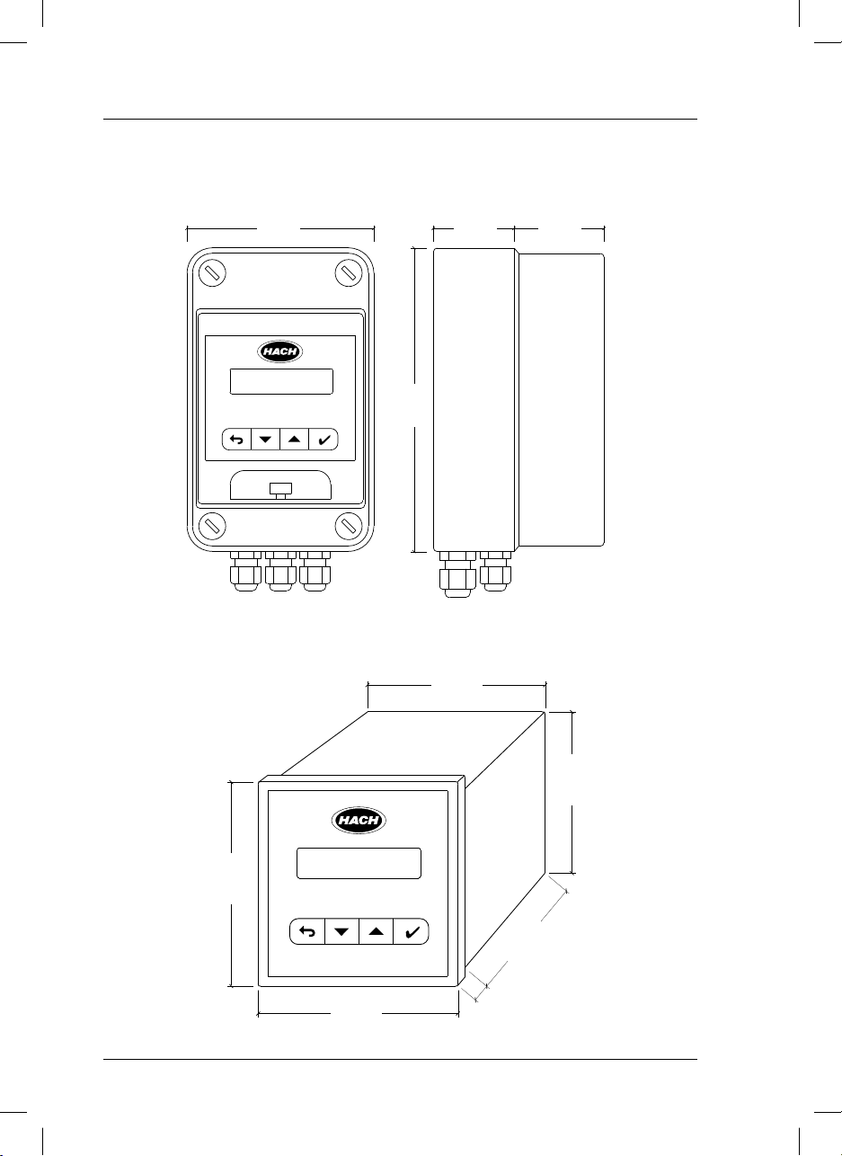
1. Technical Specifications
1.1. Dimensions
si628 C (wall mount)
105 mm
4.1 in
6.7 in
170 mm
45 mm
1.8 in
50 mm
2 in
si628 C (panel mount)
90 mm
3.5 in
3.5 in
90 mm
3.8 in
96 mm
80 mm
3.1 in
96 mm
3.8 in
4
si628 C_HACH LANGE_Ed. 0510.indd ANG:4si628 C_HACH LANGE_Ed. 0510.indd ANG:4 20/5/10 11:08:4020/5/10 11:08:40
7 mm
0.3 in
Page 9
2. General information
As a result of constant improvements to our products sometimes differences may exist between this manual
and the instructions supplied with the instrument.
ENGLISH
2.1. Safety information
Please, read carefully this information before installing and using the instrument !
Pay attention to all danger and caution statements.
2.1.1. Use of hazard information
DANGER
Indicates a potentially or imminently hazardous situation that, if not avoided, will result in death
or serious injury.
WARNING
Indicates a potentially or imminently hazardous situation that, if not avoided, may result in death
or serious injury.
CAUTION
Indicates a potentially hazardous situation that, if not avoided, may result in minor or moderate injury.
Important note
Indicates a situation that, if not avoided, could lead to damage to the instrument. Important information that requires special emphasis.
Note
Information that supplements points in the main text.
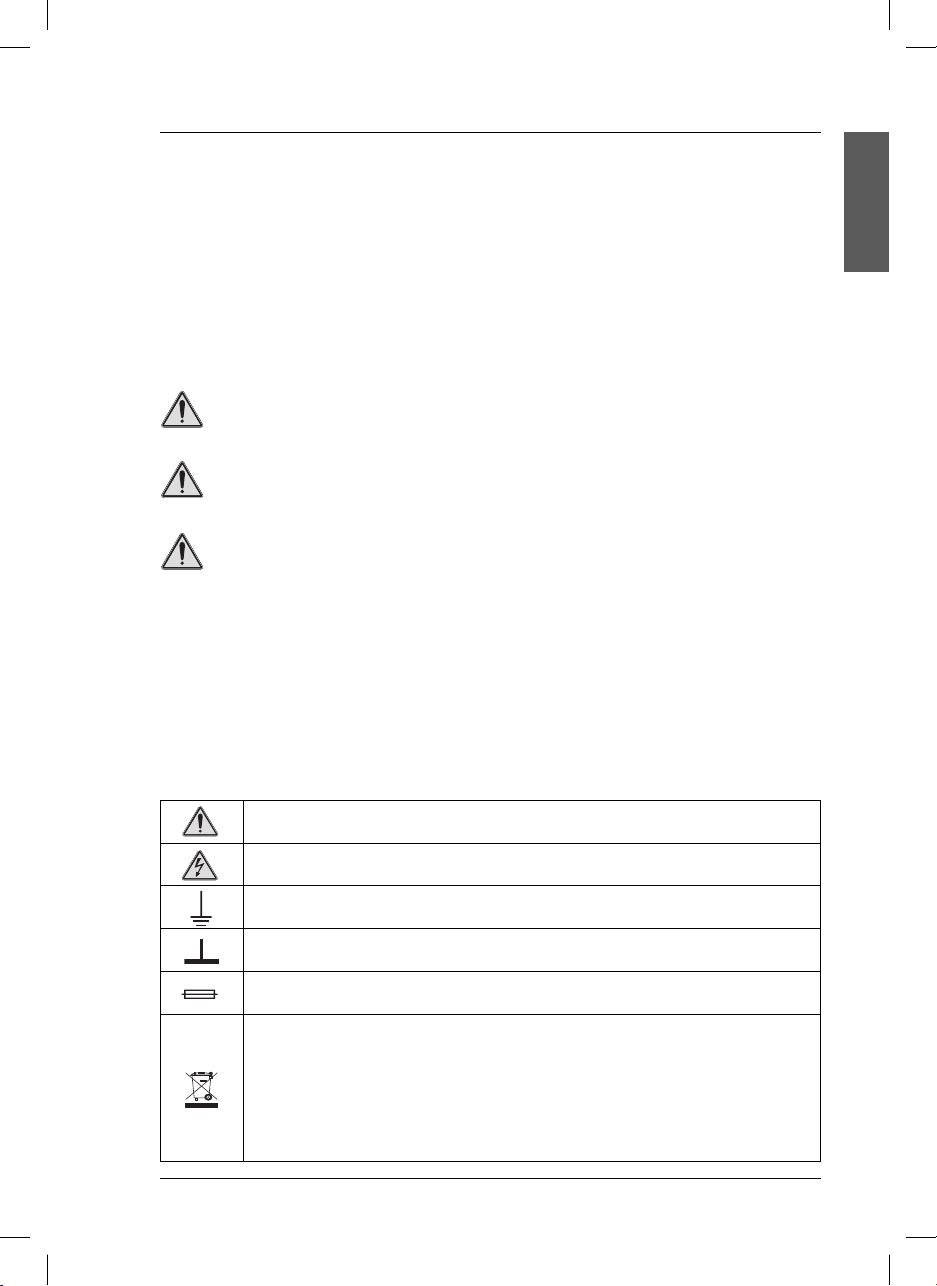
Precautionary labels
Read carefully all labels and tags attached to the instrument.
This symbol references the instruction manual for operation or safety information.
This symbol indicates that a risk of electrical shock or electrocution exists.
This symbol indicates the connection for Protective Earth.
This symbol indicates ground connection.
This symbol identifies a fuse.
Electrical equipment marked with this symbol may not be disposed of in European public disposal systems after 12 August of 2005. In conformity with European local and national regulations (EU Directive
2002/96/EC), European electrical equipment users must now return old or end-of life equipment to the
Producer for disposal at no charge to the user.
Note: For return for recycling, please contact the equipment producer or supplier for instructions on how
to return end-of-life equipment, producer-supplied electrical accessories, and all auxiliary items for proper
disposal.
5
si628 C_HACH LANGE_Ed. 0510.indd ANG:5si628 C_HACH LANGE_Ed. 0510.indd ANG:5 20/5/10 11:08:4020/5/10 11:08:40
Page 10

2. General information
DANGER
• Remember that the voltage across accessible
parts of the open instrument, may be dangerous
to life. Do not open the instrument when it is
connected to the power supply, there are areas
whose voltage could cause death.
• Always disconnect power to the instrument
before it is opened.
• Repair or adjustment of an opened instrument
under voltage shall be carried out only by
a qualified technician who is aware of the
hazards involved.
• Never work in an environment subject to
explosion hazards. The housing of the
instrument is not gas tight.
• The Company will not be responsible for any
physical damage caused by non authorised
work or manipulation.
• It is the responsibility of whoever uses this
instrument to consult and establish appropriate
safety and health practices and determine the
applicability of regulatory limitations prior to use.
• Before connecting the instrument to a power
supply unit, make sure that the mains voltage
lies within the range:
230 or 24 V AC ±10%, 45-65 Hz (standard
version).
115 V AC ±10%, 45-65 Hz (under demand).
Important notes
• Read carefully the manual of the instrument.
• Avoid direct sunlight over the instrument.
• Exclude the following environmental influences:
- vibrations
- atmospheric humidity higher than 80 %
- corrosive gases present
- temperature < 0 °C, or > 50 °C (< 32 °F, or >
122 °F).
- powerful electric and magnetic fields.
• Only use original accessories and spare parts.
• Have the instrument serviced only by the
Company Service.
2.2. General product information
Proper use
The si628 C is used for conductivity and temperature measurement in food industry, waste water, in the
environment, etc.
2.3. Items supplied
si628 C (wall mount)
• Instrument (with strips for connections).
• User manual.
6
si628 C_HACH LANGE_Ed. 0510.indd ANG:6si628 C_HACH LANGE_Ed. 0510.indd ANG:6 20/5/10 11:08:4120/5/10 11:08:41
si628 C (panel mount)
• Instrument (with strips for connections).
• Clamps to fix to the panel.
• User manual.
Page 11
3. Installation
3.1. si628 C (wall mount)
DANGER
Only qualified personnel should conduct the tasks described in this section of the manual.
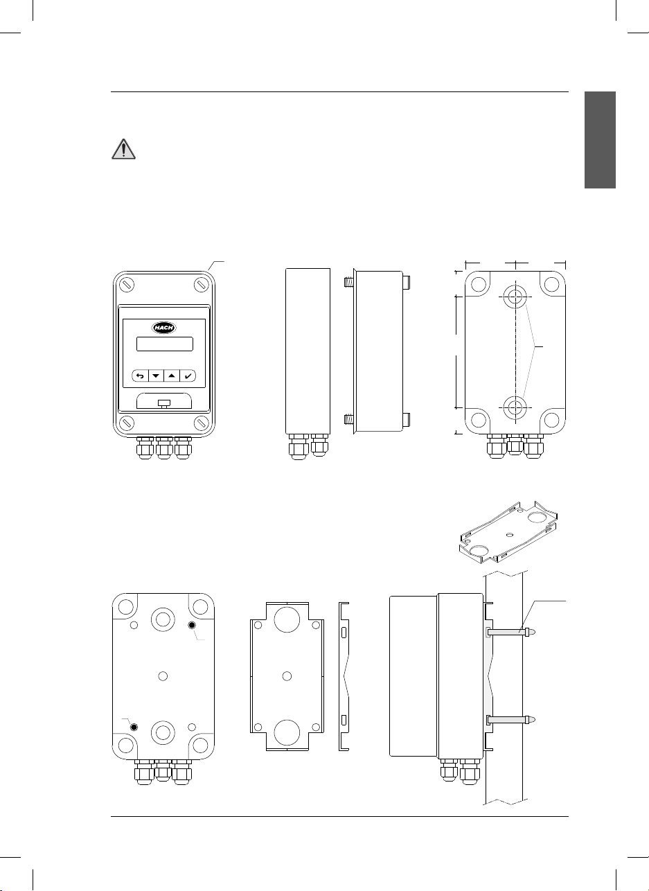
3.1.1. Assembly
Wall mounting
Open the case by unscrewing the 4 A screws.
25 mm
1 in
50 mm
2 in
A
50 mm
2 in
ENGLISH
115 mm
4.5 in
25 mm
1 in
Front view Side view Rear view
For wall mounting of the instruments, use the B drill holes indicated on the scheme.
Pipe or column mounting
Use the pipe adaptor, PN LZU9120.99.
Install the pipe adaptor on the rear part of the instrument using both C drill
holes as indicated on the figure. Fit the unit with two clamps to the column.
C
C
B
Cable
tie
Rear view Pipe adaptor Instrument mounted
7
si628 C_HACH LANGE_Ed. 0510.indd ANG:7si628 C_HACH LANGE_Ed. 0510.indd ANG:7 20/5/10 11:08:4120/5/10 11:08:41
Page 12
3. Installation
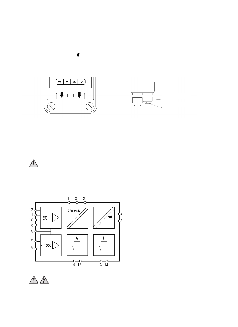
Details
To open the transparent front door, press with two
fingers the part marked with (
) in the scheme.
Cable glands.
On the lower part of the instrument there are 5
cable glands, 2 PG 7 and 3 PG 9.
PG 7 (2 units)
PG 9 (3 units)
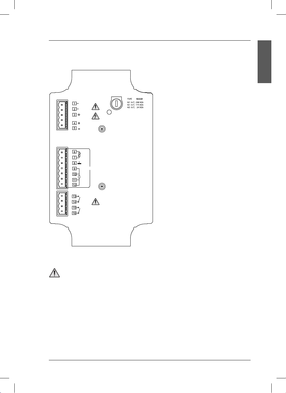
3.1.2. Connections
When making any wiring connections to the instrument, any warnings and notes found throughout the
manual must be adhered to. For more safety information see “Safety information” on page 5.
DANGER
Always disconnect power to the instrument when making any electrical connections.
System functions
1, 2 Voltage 230 or 24 VAC ± 10%.
(115 VAC under demand).
3 Ground connections, see
notes (
page 9).
4, 5 Current output 4-20 mA (EC).
6, 7 Input for temperature probe.
8 Cell cable shielding.
9 to 12 Input for 2-pole cell.
13, 14 Limit relay contacts.
15, 16 Alarm relay contacts.
DANGER
High-voltage wiring for the instrument is protected by a protective casing. The protective casing
Important
must remain in place unless a qualified installation technician is installing wiring for power.
8
si628 C_HACH LANGE_Ed. 0510.indd ANG:8si628 C_HACH LANGE_Ed. 0510.indd ANG:8 20/5/10 11:08:4220/5/10 11:08:42
Page 13
3. Installation
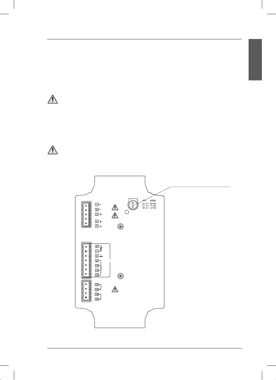
Terminal assignment (interior panel)
Important notes:
• The si628 C does not require ground connection (terminals 3).
• Connect the ground only when there could
VCA
WHEN IT IS ON, IT INDICATES A FUSED FUSE.
4-20 mA
Pt 1000
CELL
L
A
be interference problems.
ENGLISH
DANGER
Relays:
- Limit the current up to 3 A by using one fuse.
- Do not connect cables with voltage higher than 24 V.
9
si628 C_HACH LANGE_Ed. 0510.indd ANG:9si628 C_HACH LANGE_Ed. 0510.indd ANG:9 20/5/10 11:08:4220/5/10 11:08:42
Page 14
3. Installation
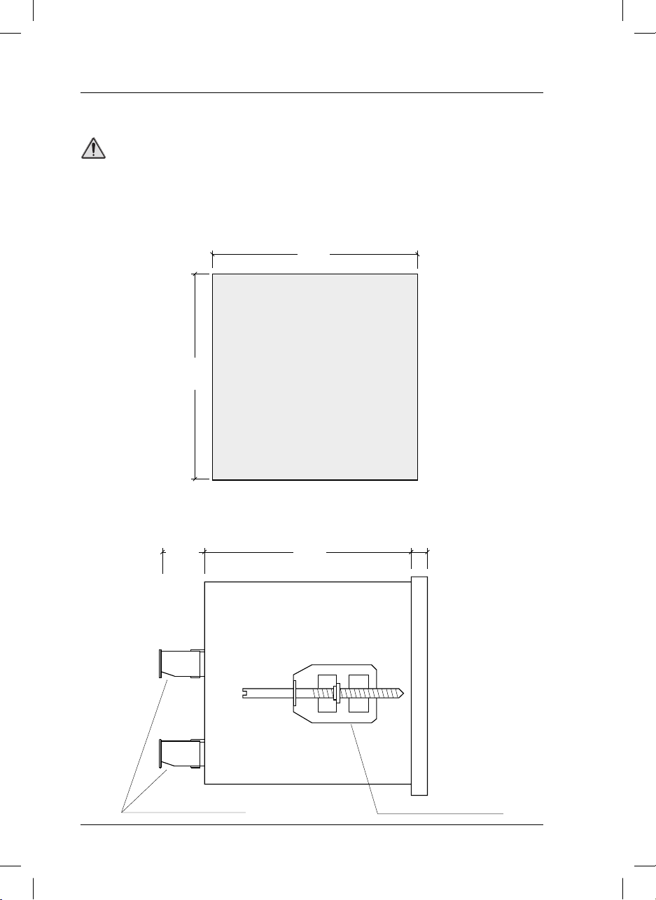
3.2. si628 C (panel mount)
DANGER
Only qualified personnel should conduct the tasks described in this section of the manual.
3.2.1. Assembly
For the si628 C mounting a drill hole is required according to the diagram.
92 mm
3.7 in
3.7 in
92 mm
Drill hole
Panel
After putting the instrument in the panel, it must be fitted using two clamps as indicated in the figure.
21 mm
0.8 in
80 mm
3.1 in
7 mm
0.3 in
Plug-in screw connector
10
si628 C_HACH LANGE_Ed. 0510.indd ANG:10si628 C_HACH LANGE_Ed. 0510.indd ANG:10 20/5/10 11:08:4320/5/10 11:08:43
Side view
Clamp to fix to the panel
Page 15
3. Installation
When making any wiring connections to the instrument, any warnings and notes found throughout the
manual must be adhered to. For more safety information see “Safety information” on page 5.
DANGER
Always disconnect power to the instrument when making any electrical connections.
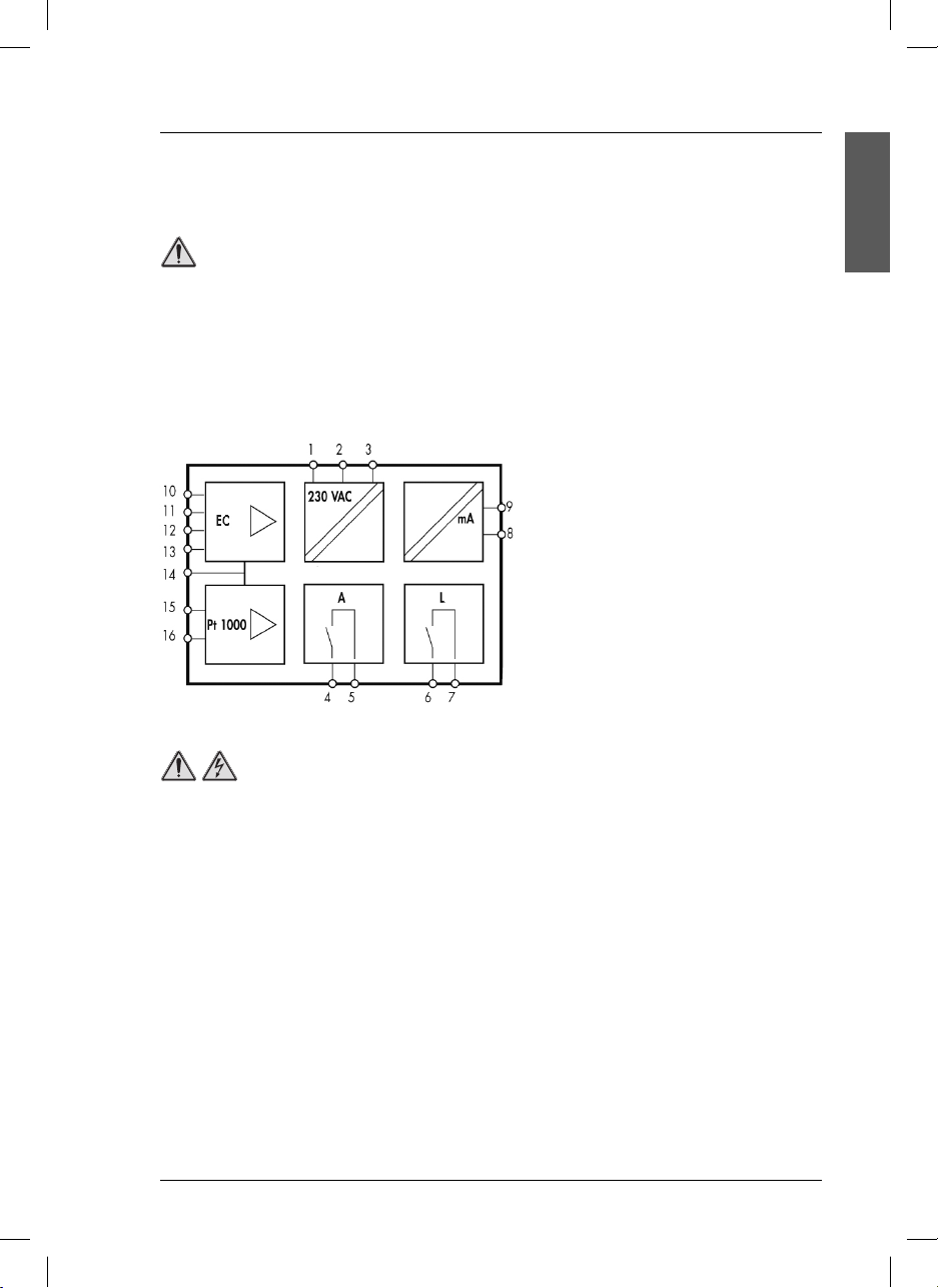
3.2.2. Connections
System functions
1 Ground connection, see Important
notes (page 12).
2, 3 Power supply 230 or 24 VAC ± 10%.
(115 VAC under demand).
4, 5 Alarm relay contacts.
6, 7 Limit relay contacts.
8, 9 Current output 4-20 mA (EC).
10 to 13 Input for 2-pole cell.
14 Cell cable shielding.
15, 16 Input for temperature probe.
DANGER
High-voltage wiring for the instrument is protected by a protective casing. The protective casing
must remain in place unless a qualified installation technician is installing wiring for power.
ENGLISH
11
si628 C_HACH LANGE_Ed. 0510.indd ANG:11si628 C_HACH LANGE_Ed. 0510.indd ANG:11 20/5/10 11:08:4320/5/10 11:08:43
Page 16
3. Installation
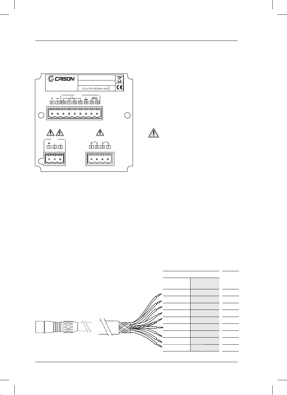
Terminal assignment (rear panel)
Notas importantes:
• El si628 C
does not require ground connec-
tion (terminal 1).
• Connect the ground only when there could
CRISON INSTRUMENTS, S.A.
E-08328 ALELLA - Barcelona
Made in Spain
CELL4-20 mA
Transmitter si628 C
S/N:
IP 54
be interference problems.
DANGER
RED
VCA
L 1 L 2
Relays:
- Limit the current up to 3 A by using
one fuse.
- Do not connect cables with voltage
higher than 24 V.
3.3. Cell cables
Compensation of the cable length
To minimize the effect of the cable resistance in a conductivity measurement, the cable length is compensated by the 4-wire system. With the Pt 1000 temperature sensor, the cable resistance has little importance.
However, in order to reduce the resistance of the conductor to a half, 2 cables have been connected to
the ends of the sensor.
3.3.1. Cells with MP-5 connector
MP-5 connector, 5 contacts
TERMINALS
si628 C
(wall mount)
616 White
616 Brown
715 Pink
7 15 Yellow
814 Shield
913 Green
10 12 Blue
11 11 Gray
12 10 Red
si628 C
(panel mount)
COLOUR
12
si628 C_HACH LANGE_Ed. 0510.indd ANG:12si628 C_HACH LANGE_Ed. 0510.indd ANG:12 20/5/10 11:08:4320/5/10 11:08:43
Page 17
3. Installation
3.3.2. Cells with connector S8
TERMINALS
si628 C
(wall mount)
9 13 Middle
10 12 Middle
11 11 Shield
12 10 Shield
si628 C
(panel mount)
COLOUR
ENGLISH
Important note:
Fit a jumper between terminals 9 and 10 (12 and 13 in panel mount instrument) and another between
the terminals 11 and 12 (10 and 11 in panel mount instrument).
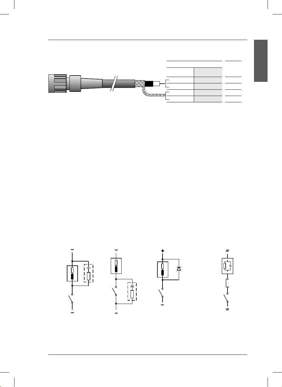
3.4. Protective wiring of switching contacts
Relay contacts are subjected to electrical erosion.
Especially with inductive and capacitive loads, the service life of the contacts will be reduced.
For suppression of sparks and arcing, components such as RC combinations, nonlinear resistors, series
resistors and diodes should be used.
Typical protective wirings
AC applications with inductive load
DC applications with
inductive load
AC/DC with
capacitive load
RC
Load
RC
Contact
relay
Typical RC at 230 VAC: Capacitor 0.1 µF/630 V
Resistor 100 Ω/1 W
Diode
1N4007
Maximum relays load: AC < 24 V / < 3 A / < 72 VA.
si628 C_HACH LANGE_Ed. 0510.indd ANG:13si628 C_HACH LANGE_Ed. 0510.indd ANG:13 20/5/10 11:08:4320/5/10 11:08:43
Load
R
R, for example:
5 Ω / 1 W at
24 V / 0.4 A
13
Page 18
4. Operation
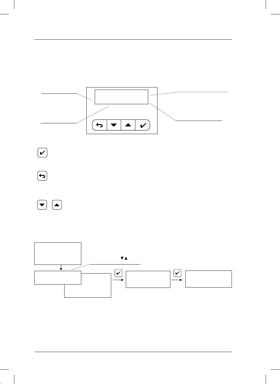
4.1. Description
Display
si628 C have an alphanumeric display that explains itself. One of the most significant screens is described below as an example:
Measured value.
Measuring units.
Keys
MEASURING 23.2 °C
538 µS/cm @25 °C
ENTER.
• Horizontal movements to move forward in the “diagram”.
• Acceptance of numerical values.
ESCAPE.
• Horizontal movements to move back in the “diagram”.
• Vertical movements to move back in the “diagram”.
• To erase numerical values.
• Modification of numerical values.
• Cursor “>” movements on the screen.
Sample temperature
Resolution:
1 °C manual selection.
0.1 °C measuring with Pt 1000
Reference temperature
4.2. Setting up
Connect the si628 C to mains. At power up the first time only the following screens will appear:
si628_C
V1.0
LANGUAGE >Español
Italiano
The instrument is already measuring conductivity,
with the following configuration:
• Temperature coefficient, CT, fixed at 2% / °C.
• Cell constant C=1 cm
• Reference temperature, RT, fixed at 25°C.
• Limit relay is activated at 1000 µS/cm, and
desactivated at 800 µS/cm.
14
si628 C_HACH LANGE_Ed. 0510.indd ANG:14si628 C_HACH LANGE_Ed. 0510.indd ANG:14 20/5/10 11:08:4420/5/10 11:08:44
Possibility to select other
language with keys.
Français
English
Deutsch
Português
-1
.
MEASURE S/cm
• Alarm relay is activated after 1minute with the
reading out of limit.
• Output current 4 mA = 200 µS/cm, 20 mA =
2000 µS/cm.
To modify the default configuration (except from
the temperature Coefficient and the reference temperature) see page 16.
MEASURING 22.3°C
µS/cm
545
@25°
Page 19
4. Operation
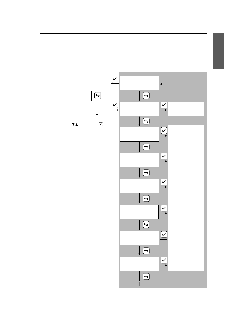
4.3. Quick guide
This page shows the instrument’s operation by blocks. It is intended to provide a quick idea about all the
instrument’s capabilities and how to gain access to them
MEASURING 22.3°C
545
µS/cm
@25°
MEASURE S/cm
ENGLISH
Security access
code.
It limits the access
to calibration
or programming
of the instrument
CÓDIGO 000
Vary the underlined digit with
and accept with .
Authorised code = 100
by non authorised
people.
When the “Code” screen has been shown for
more than 30 sec. the instrument will automatically
return to MEASURE.
Instrument in hold state.
When being in the grey zone, the
instrument is in hold state:
• Contact relays are opened.
• According to the configuration, the
current output is frozen at 21 mA or
at the mA corresponding to the last
measured value.
To quit the hold state it is necessary to
return to MEASURE. The current output
4 to 20 will activate in 10 sec.
CALIBRATE
CELL
LIMIT
ALARM
OUTPUT 4-20 MA
HOLD
LANGUAGE
See “calibration... “
( page 17)
See “programming...”
( page 16)
15
si628 C_HACH LANGE_Ed. 0510.indd ANG:15si628 C_HACH LANGE_Ed. 0510.indd ANG:15 20/5/10 11:08:4520/5/10 11:08:45
Page 20
4. Operation
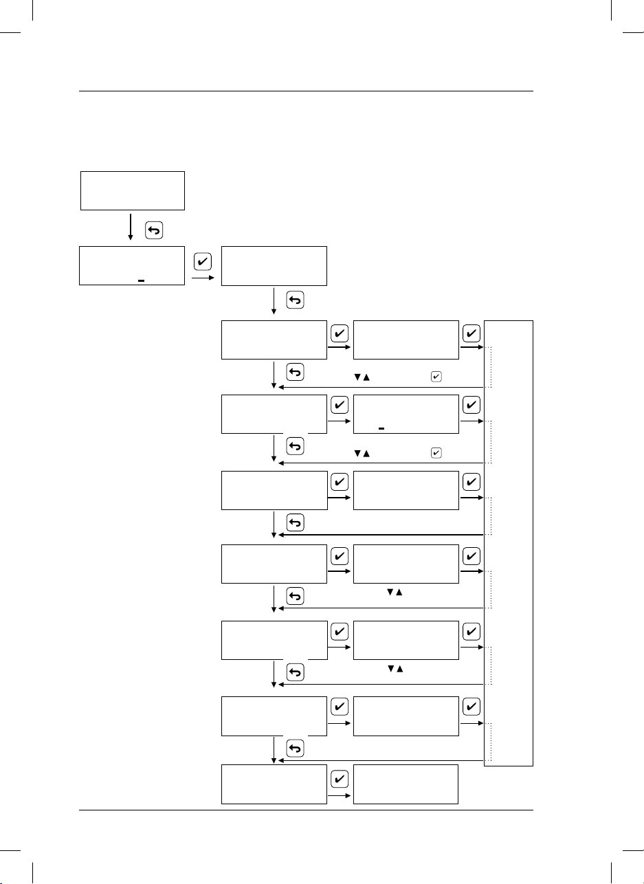
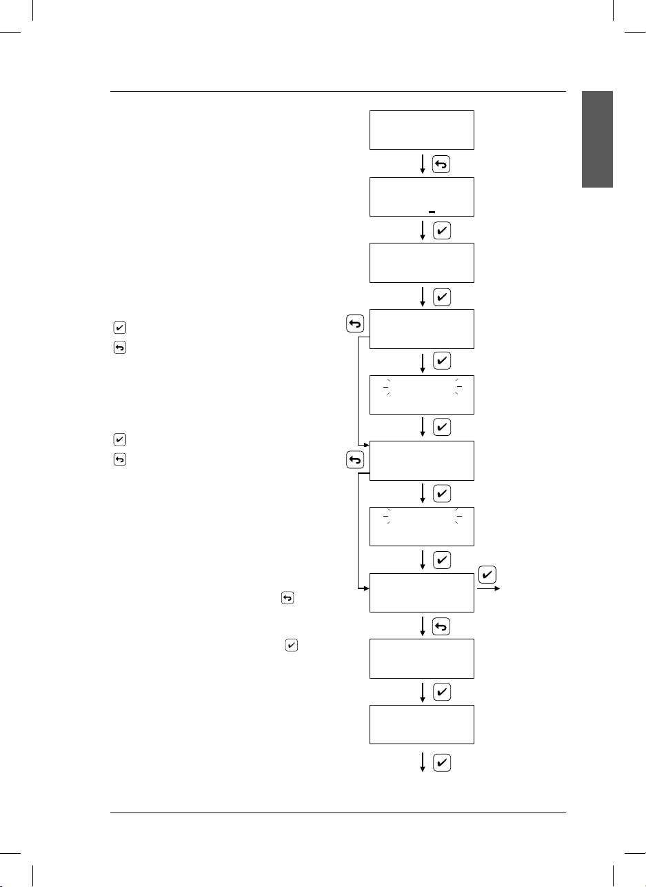
4.4. Programming
The instrument is supplied with the default configuration specified in Setting up, page 14.
To modify the default configuration and adapt it to specific applications follow the diagram below.
MEASURING 22.3°C
µS/cm
545
@25°
CODE 000
Enter code 100.
Select the nominal value of cell
constant to be used. If the exact
value is known, it can be directly
entered, avoiding the calibration
procedure.
Selection of the functioning
values of the corresponding
relays.
Input “ON” (closed contact).
Output “OFF” (open contact).
Selectable values between
0.0 µS and 200 mS.
Select the time before the alarm
activation.
Selectable between 1 to 99 min
or hours. 0= deactivated.
Select the conductivity values
corresponding to the Current
Output (4 mA and 20 mA).
Selectable values between
0.0 µS and 200 mS.
CALIBRATE
CELL
LIMIT (*)
ALARM
OUTPUT 4-20 mA
Note: When programming, the instrument is
in hold state:
• The contact relays are open.
• The current output is frozen at 21 mA.
To quit the hold state it is necessary to return
to MEASURE.
CONST:
1.000 cm
Vary the underlined digit with
and accept with
–1
ON - - - - - - OFF
1000 µS 800 µS
Vary the underlined digit with
and accept with
ALARM:
01 min
4 mA 20 mA
pH: 0.0 2.0 mS
Vary with
STORING DATA
Selection of the current output
when the instrument is in Hold
state: fixed at 21 mA or at the
mA corresponding to the last
measured value.
Selection of the working
language: English, German,
Spanish, French, Italian,
Portuguese.
(*) LIMIT and OUTPUT 4-20 mA:
Allows the introduction of five
digits, placing the decimal point
you want.
16
si628 C_HACH LANGE_Ed. 0510.indd ANG:16si628 C_HACH LANGE_Ed. 0510.indd ANG:16 20/5/10 11:08:4520/5/10 11:08:45
HOLD
LANGUAGE
MEASURE S/cm
> 21 mA
last
Vary with
LANGUAGE > Español
Italiano
MEASURING 22.3°C
µS/cm
545
@25°
Page 21
4. Operation
4.5. Calibration
With the calibration the instrument adapts to the cell
MEASURING 22.3°C
545
and its variations with time. Therefore a periodical calibration is necessary.
Calibration can be carried out with 1 or 2 standards,
to be selected between: 147 µS/cm, 1413 µS/cm or
12.88 mS/cm. If it appears an anomaly during the
calibration process an error message will be displayed
(see page 22).
If the cell constant value is exactly known, it can be
manually entered (see page 16) avoiding the calibration procedure.
starts calibration with the standard 147 µS/cm.
selects the next standard, 1413 µS/cm, to perform
calibration.
Theoretical value of the standard at the calibration
temperature.
starts calibration with standard 1413 µS/cm.
selects the next standard, 12.88 mS/cm, to perform
calibration.
23.2°C
Standard 147 µS/cm
Standard 1413 µS/cm
µS/cm
@25°
CODE 000
CALIBRATE
CAL. 23.2°C
142.6 µS/cm
23.2°C
CAL. 23.2°C
1364 µS/cm
ENGLISH
Introduce the code
100.
If you have a cell
without CAT, manually
enter the temperature
value.
Once the reading
is stable, the
display changes
automatically.
Calibration can be carried out with 1 or 2 standards. If the
calibration is with only one standard, press
P1, first standard used. C1, cell constant.
If the calibration was with 2 standards, press
P2 and C2.
.
to display
23.2°C
Standard 12.88 mS/cm
P1=147,0 µS/cm
C
=0,393 cm
1
-1
Press to
perform
calibration with
this standard.
P2=1413,0 µS/cm
C
=0,397 cm
Note: In calibration the instrument is in Hold state:
• Contact relays are opened.
• Current output is fixed at 21 mA.
To quit the Hold estate it is necessary to return to MEASURE.
si628 C_HACH LANGE_Ed. 0510.indd ANG:17si628 C_HACH LANGE_Ed. 0510.indd ANG:17 20/5/10 11:08:4620/5/10 11:08:46
2
to MEASURE
-1
17
Page 22

4. Operation
4.5.1. Recognized standards
Table of values according to temperature.
Values stored in the si628 C.
°C µS/cm µS/cm mS/cm
15.0 119 1147 10.48
16.0 122 1173 10.72
17.0 125 1199 10.95
18.0 127 1225 11.19
19.0 130 1251 11.43
20.0 133 1278 11.67
21.0 136 1305 11.91
22.0 139 1332 12.15
23.0 142 1359 12.39
24.0 145 1386 12.64
25.0 147 1413 12.88
26.0 150 1440 13.13
27.0 153 1467 13.37
28.0 156 1494 13.62
29.0 159 1522 13.87
30.0 162 1549 14.12
18
si628 C_HACH LANGE_Ed. 0510.indd ANG:18si628 C_HACH LANGE_Ed. 0510.indd ANG:18 20/5/10 11:08:4720/5/10 11:08:47
Page 23
4. Operation
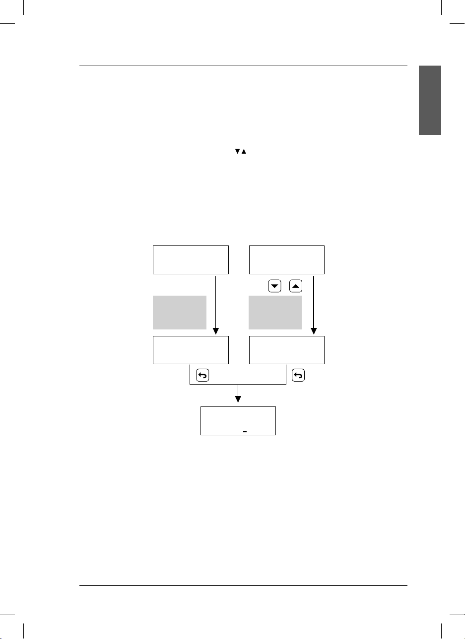
4.6. Measure
Conductivity and temperature measurement
The value of the specific conductivity, the sample temperature in °C and the reference temperature
appear simultaneously on the display.
If the Pt 1000 temperature probe is not connected it is necessary to inform the instrument about the
temperature of the solution using the arrow keys
Conductivity cells incorporate a Pt 1000 temperature sensor.
Conductivity measurement
... with Pt 1000 probe ... without Pt 1000 probe
.
ENGLISH
MEASURING 22.3°C
µS/cm
545
Temperature
automatically
@25°
measured
MEASURING 22.3°C
µS/cm
545
@25°
CODE 000
MEASURING 25°C
µS/cm
545
temperature
@25°
Manually
entered
MEASURING 22°C
µS/cm
565
@25°
19
si628 C_HACH LANGE_Ed. 0510.indd ANG:19si628 C_HACH LANGE_Ed. 0510.indd ANG:19 20/5/10 11:08:4720/5/10 11:08:47
Page 24
4. Operation
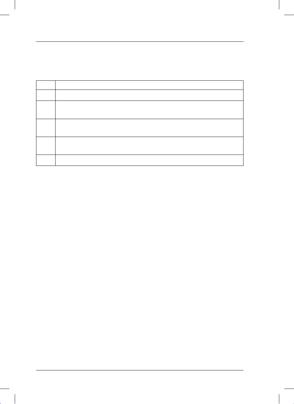
4.7. Access codes
The code 100 is for access to the calibration and programming of the instrument.
There are codes with other functions:
Code Action
100 Main Menu.
401 Modification of the relay lag of the limits relays activation and deactivation.
Standard value: 2s. Programmable values: 0 to 99 s
413 Modification of the time for alarm activation when there is out of range reading.
Standard value: 60 s. Programmable values: 0 to 99 s/min/h
473 Modification of the delay time activation of the analogical output 4 to 20 mA after quitting Hold.
Standard value: 10 s. Programmable values: 0 to 99 s
497 Possibility to adjust the temperature for minimizing the effect of long cables.
20
si628 C_HACH LANGE_Ed. 0510.indd ANG:20si628 C_HACH LANGE_Ed. 0510.indd ANG:20 20/5/10 11:08:4720/5/10 11:08:47
Page 25
5. Maintenance
5.1. Clean the measuring instrument and accessories
Important note: Never use cleaning such as turpentine, acetone or similar products to clean the instrument
including the display and accessories.
Only clean the housing and accessories using a soft, damp cloth. Mild soap solution may also be used. Dry
the cleaned parts carefully with a soft cotton cloth.
CAUTION
When using chemicals or solvents, comply with the instructions of the producer and the general
safety rules.
5.2. Fuse replacement (only in si628 C wall mount)
DANGER
Always disconnect power to the instrument when replacing the fuse
Unscrew for fuse replacement.
ENGLISH
VCA
WHEN IT IS ON, IT INDICATES A FUSED FUSE.
4-20 mA
Pt 1000
CELL
L
A
21
si628 C_HACH LANGE_Ed. 0510.indd ANG:21si628 C_HACH LANGE_Ed. 0510.indd ANG:21 20/5/10 11:08:4720/5/10 11:08:47
Page 26
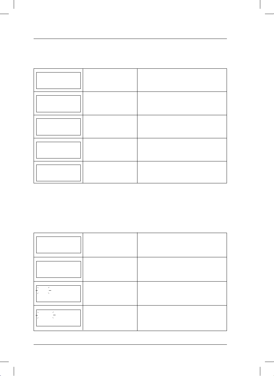
6. Error messages
During calibration
On display Problem Possible causes
Error C
Unstable reading
> 30 %
Deviation of the cell constant
value higher than 30 % of its
nominal value.
Unstable reading for more
than 60 s.
Cell “worn out”.
Error in the selection of the cell.
Verify programming.
Defective or dirty cell.
Standard from the refrigerator.
more than 1 min.
Same standard was used for both calibration
points.
Press ESC to quit calibration.
The standard used is not among the 3 in memory:
147 µS/cm, 1413 µS/cm or 12.88 mS/cm. at
25 °C. Press ESC to quit calibration.
SAME STANDARD
UNKOWN
STANDARD
°C OUT OF RANGE
1st and 2nd buffer have the
same nominal value.
Incorrect buffer solution.
Standards temperature. Standard temperature > 35 °C or < 10 °C.
Other messages
On display Problem Possible causes
OUT OF R. 22.3°C
Measured value out of
range.
- - - - -- mS/cm @25°
Conductivity reading > 200 mS/cm.
After 1 minute, the current output will remain fixed
at 22 mA.
°C OUT OF RANGE
Measured temperature value
out of limits.
13.37 mS/cm @25°
LIMIT 22.3 °C
835 µS/cm @25°
ALARM 22.3°C
Measured value out of the
programmed limits
L1 and/or L2.
Activation of the alarm relay
835 µS/cm @25°C
22
si628 C_HACH LANGE_Ed. 0510.indd ANG:22si628 C_HACH LANGE_Ed. 0510.indd ANG:22 20/5/10 11:08:4820/5/10 11:08:48
Pt 1000 probe broken or temp. < –20 or >150°C.
After 1 minute the current output will remain fixed
at 22 mA.
Verify the programmed limit values.
Verify process evolution.
The conductivity value is off limits for longer than
the programmed delay of alarm relay activation.
The current output will be set at 22 mA, but the
limit will continue to relay on.
Page 27

7. Replacement parts
P/N Description
LZU1001.99 0.1 A, fuse for si628 C 230 and 115 VCA (only wall mount).
LZU1002.99 0.5 A, fuse for si628 C 24 VCA (only wall mount).
LZU1004.99 Clamps to fix si628 C (only panel mount).
LZU9120.99 Pipe adaptor for si628 C (only wall mount).
LZU1003.99 Coaxial cable with AS9 connector, 3 m.
LZU1005.99 Coaxial cable with AS9 connector, 5 m.
LZU1010.99 Coaxial cable with AS9 connector, 10 m.
LZU1015.99 Coaxial cable with AS9 connector, 15 m.
LZU1020.99 Coaxial cable with AS9 connector, 20 m.
LZU1025.99 Coaxial cable with AS9 connector, 25 m.
LZU9044.99
LZU9045.99
LZU9046.99
LZU9047.99
LZU9251.99
LZU1199.99
LZW9700.99 Conductivity standard solution 147 µS/cm, with certificate of analysis, 250 ml flask.
LZW9710.99 Conductivity standard solution 1413 µS/cm, with certificate of analysis, 250 ml flask.
LZW9720.99 Conductivity standard solution 12.88 mS/cm, with certificate of analysis, 250 ml flask.
LZW9730.99 Conductivity standard solution 80.4 mS/cm, with certificate of analysis, 250 ml flask.
LZW9731.99 Conductivity standard solution 80.4 mS/cm, with certificate of analysis, 1000 ml flask.
LZW9740.99 Conductivity standard solution 111.8 mS/cm, with certificate of analysis, 250 ml flask.
LZW9741.99 Conductivity standard solution 111.8 mS/cm, with certificate of analysis, 1000 ml flask.
For cells please ask for specific brochure.
Multiple cable with MP-5 connector, 3 m.
Multiple cable with MP-5 connector, 5 m.
Multiple cable with MP-5 connector, 10 m.
Multiple cable with MP-5 connector, 15 m.
Multiple cable with MP-5 connector, 20 m.
MP-5 connector, for multiple cables connectable to conductivity cells, temperature compensators and
chlorine galvanic cells.
ENGLISH
23
si628 C_HACH LANGE_Ed. 0510.indd ANG:23si628 C_HACH LANGE_Ed. 0510.indd ANG:23 20/5/10 11:08:4820/5/10 11:08:48
Page 28

8. Warranty and liability
The manufacturer warrants that the product supplied is free of material and manufacturing defects and
undertakes the obligation to repair or replace any defective parts at zero cost.
The warranty period for instruments is 24 months. If a service contract is taken out within 6 months of purchase, the warranty period is extended to 60 months.
With the exclusion of the further claims, the supplier is liable for defects including the lack of assured properties as follows: all those parts that, within the warranty period calculated from the day of the transfer of
risk, can be demonstrated to have become unusable or that can only be used with significant limitations
due to a situation present prior to the transfer of risk, in particular due to incorrect design, poor materials or
inadequate finish will be improved or replaced, at the supplier’s discretion. The identification of such defects
must be notified to the supplier in writing without delay, however at the latest 7 days after the identification
of the fault. If the customer fails to notify the supplier, the product is considered approved despite the defect.
Further liability for any direct or indirect damages is not accepted.
If instrument-specific maintenance and servicing work defined by the supplier is to be performed within the
warranty period by the customer (maintenance) or by the supplier (servicing) and these requirements are not
met, claims for damages due to the failure to comply with the requirements are rendered void.
Any further claims, in particular claims for consequential damages cannot be made.
Consumables and damage caused by improper handling, poor installation or incorrect use are excluded
from this clause.
The manufacturer process instruments are of proven reliability in many applications and are therefore often
used in automatic control loops to provide the most economical possible operation of the related process.
To avoid or limit consequential damage, it is therefore recommended to design the control loop such that
a malfunction in an instrument results in an automatic change over to the backup control system; this is the
safest operating state for the environment and the process.
24
si628 C_HACH LANGE_Ed. 0510.indd ANG:24si628 C_HACH LANGE_Ed. 0510.indd ANG:24 20/5/10 11:08:4820/5/10 11:08:48
Page 29

Inhalt
1. Technische Daten . . . . . . . . . . . . . . . . . . . . . . . . . . 3
1.1. Abmessungen
2. Allgemeine Informationen . . . . . . . . . . . . 5
2.1. Sicherheitshinweise
2.1.1. Bedeutung von Gefahrenhinweisen
2.2. Allgemeine Produktinformationen
2.3. Inhalt
. . . . . . . . . . . . . . . . . . . . . . . . . . . . . . . 6
. . . . . . . . . . . . . . . . . . . . . . . . . 4
. . . . . . . . . . . . . . . . . . . . . 5
5
. . . . . . . . . 6
3. Montage und Installation
3.1. si628 C (Wandmontage)
3.1.1. Montage
3.1.2. Anschlüsse
3.2. si628 C (Schalttafelmontage)
3.2.1. Montage
3.2.2. Anschlüsse
3.3. Zellenkabel
. . . . . . . . . . . . . . . . . . . . . . . . . . . . 12
. . . . . . . . . . . . . . . . . . 7
. . . . . . . . . . . . . 7
. . . . . . . . . . . . . . . . . . . . . . . . 7
. . . . . . . . . . . . . . . . . . . . . . . 8
. . . . . . . . 10
. . . . . . . . . . . . . . . . . . . . . . . . 10
. . . . . . . . . . . . . . . . . . . . . . . 11
3.4. Einbau von Schutzvorrichtungen für die
Relaiskontakte
4. Bedienung und Funktion
4.1. Beschreibung
4.2. Inbetriebnahme
4.3. Kurzanleitung
4.4. Programmierung
4.5. Kalibrierung
4.5.1. Geeignete Standards
4.6. Messung
4.7. Zugangscodes
5. Wartung
. . . . . . . . . . . . . . . . . . . . . . . . . . . . . . . 21
5.1. Reinigung des Geräts und des Zubehörs
. . . . . . . . . . . . . . . . . . . . . . . . . . 13
. . . . . . . . . . . . . . . . . . 14
. . . . . . . . . . . . . . . . . . . . . . . . . . 14
. . . . . . . . . . . . . . . . . . . . . . . . 14
. . . . . . . . . . . . . . . . . . . . . . . . . . 15
. . . . . . . . . . . . . . . . . . . . . . . . 16
. . . . . . . . . . . . . . . . . . . . . . . . . . . 17
. . . . . . . . . . . . . 18
. . . . . . . . . . . . . . . . . . . . . . . . . . . . . . 19
. . . . . . . . . . . . . . . . . . . . . . . . . 20
. . 21
5.2. Austausch der Sicherung . . . . . . . . . . . . . . . . 21
DEUTSCH
6. Fehlermeldungen
7. Ersatzteile
8. Gewährleistung und Haftung
. . . . . . . . . . . . . . . . . . . . . . . . . 22
. . . . . . . . . . . . . . . . . . . . . . . . . . . . . . . 23
. . . . . . . . . . . . 24
Contact information
1
si628 C_HACH LANGE_Ed. 0510.indd ALE:1si628 C_HACH LANGE_Ed. 0510.indd ALE:1 20/5/10 11:08:4820/5/10 11:08:48
Page 30

si628 C_HACH LANGE_Ed. 0510.indd ALE:2si628 C_HACH LANGE_Ed. 0510.indd ALE:2 20/5/10 11:08:4820/5/10 11:08:48
Page 31

1. Technische Daten
Messbereiche
Leitfähigkeit* 0,01 µS/cm bis 199,9 mS/cm
*mit Messzelle C = 0,1 cm
-1
°C: –20,0 bis 150,0
Messfehler
Leitfähigkeit ≤ 1 % (±1 Stelle)
Temperatur ≤ 0,5 °C (±1 Stelle)
Reproduzierbarkeit
Leitfähigkeit ±0,1 % (±1 Stelle)
Temperatur ±0,1 °C (±1 Stelle)
Automatische Temperaturkompensation
Mit Temperatursensor (Pt 1000) oder
Dateneingabe über Tastatur
Temperaturkoeffizient, TK
Konstant 2 % / °C
Referenztemperatur, RT
Konstant 25 °C
Geeignete Messzellen
Mit zwei Elektroden, Zellkonstante: 0,05 bis
-1
50 cm
Geeignete Standards
147 µS/cm, 1413 µS/cm und 12,88 mS/cm
(25 °C)
Kalibrierungsoptionen
Mit 1 oder 2 Standards
Zugangscode (Festcode): 100
Kalibrierungsannahme, 2 Standards
Abweichung < 30 % zwischen den ermittelten
Zellkonstanten
Relaiskonfiguration
EIN/AUS
1 Relais, als oberer oder unterer Grenzwert
programmierbar
Relaisverzögerung: 2 Sekunden
Alarmrelais, zwischen 1 und 99 Sekunden, Minuten oder Stunden programmierbar
Sprachen
Englisch, Deutsch, Spanisch, Französisch, Italienisch,
Portugiesisch
Display
LCD, alphanumerisch, von hinten beleuchtet,
2 Zeilen zu je 16 Buchstaben
Eingänge und Ausgänge
Galvanisch isolierter Analogausgang:
• 4 bis 20 mA für die Messung (R max.= 500 Ω)
• 21 mA oder mA-Wert entsprechend dem letzten
Messwert für den Haltemodus (Hold)
• 22 mA für Alarm
Relais
1 Grenzwertrelais, potenzialfrei. Schließerkontakt
1 Alarmrelais, potenzialfrei. Öffnerkontakt
Maximallast:
bei AC < 24 V / < 3 A / < 72 VA
Maximale Kabellänge
≤ 25 m
Spannungsversorgung
230 oder 24 VAC ±10 %, 45–65 Hz,
Standardausführungen. (115 VAC auf Anfrage)
Leistungsaufnahme: 4 VA
Schutzklasse II
Überspannungskategorie II
EG-Richtlinien
Gemäß Niederspannungsrichtlinie 2006/95/EG
Elektromagnetische Verträglichkeit gemäß
Richtlinie 2004/108/EG
Umgebungsbedingungen
Betriebstemperatur:
0 bis 50 °C (32 bis 122 °F)
Lagertemperatur:
-20 bis 65 °C (-4 bis 149 °F)
Relative Feuchtigkeit: < 80 % (nicht kondensiert)
Max. Höhe 2.000 m bei 230 V; 3.000 m bei 24 V
Gehäuse
si628 C (Wandmontage): thermoplastisches
Material, Schutzart IP55
si628 C (Schalttafelmontage): Noryl, Schutzart
frontseitig IP54. Brennbarkeit: FV-1
Gewicht
si628 C (Wandmontage): 700 g
si628 C (Schalttafelmontage): 600 g
Abmessungen
si628 C (Wandmontage):
105 x 170 x 100 mm (4 x 6,7 x 3,9 in)
si628 C (Schalttafelmontage):
96 x 96 x 100 mm (3,8 x 3,8 x 3,9 in)
Garantie
Geräte: 2 Jahre
2-polige Messzelle, Klemmleistenanschluss
Temperatursensor, Typ Pt 1000, Klemmleistenanschluss
Technische Daten können jederzeit ohne Vorankündigung geändert werden.
DEUTSCH
. Brennbarkeit: HB
3
si628 C_HACH LANGE_Ed. 0510.indd ALE:3si628 C_HACH LANGE_Ed. 0510.indd ALE:3 20/5/10 11:08:4820/5/10 11:08:48
Page 32

1. Technische Daten
1.1. Abmessungen
si628 C (Wandmontage)
105 mm
4.1 in
6.7 in
170 mm
45 mm
1.8 in
50 mm
2 in
si628 C (Schalttafelmontage)
90 mm
3.5 in
3.5 in
90 mm
3.8 in
96 mm
80 mm
3.1 in
96 mm
3.8 in
4
si628 C_HACH LANGE_Ed. 0510.indd ALE:4si628 C_HACH LANGE_Ed. 0510.indd ALE:4 20/5/10 11:08:4820/5/10 11:08:48
7 mm
0.3 in
Page 33

2. Allgemeine Informationen
Da wir unsere Geräte laufend verbessern, können Unterschiede zwischen den Informationen in dieser
Bedienungsanleitung und dem von Ihnen erworbenen Gerät nicht ausgeschlossen werden.
2.1. Sicherheitshinweise
Lesen Sie die vorliegende Bedienungsanleitung vor der Montage und Installation des Geräts vollständig
durch.
Beachten Sie alle Warnetiketten.
2.1.1. Bedeutung von Gefahrenhinweisen
GEFAHR
Weist auf eine potenzielle oder unmittelbare Gefahrensituation hin, deren Nichtbeachtung zu
ernsthaften Verletzungen oder sogar zum Tod führt.
WARNUNG
Weist auf eine potenzielle oder unmittelbare Gefahrensituation hin, deren Nichtbeachtung zu
ernsthaften Verletzungen oder sogar zum Tod führen kann.
VORSICHT
Weist auf eine mögliche Gefahrensituation hin, die zu leichten bis mittelschweren Verletzungen
führen kann.
Wichtiger Hinweis: Weist auf eine Situation hin, die zu Schäden am Gerät führen kann. Wichtige
Information, die beim Umgang mit dem Gerät besonders zu beachten ist.
Hinweis: Zusätzliche Information über den Umgang mit dem Gerät.
DEUTSCH
Warnetiketten
Beachten Sie alle am Gerät angebrachten Etiketten, Schilder und Aufkleber.
Dieses Symbol verweist auf Bedienungs- und/oder Sicherheitshinweise in der Bedienungsanleitung.
Dieses Symbol weist auf Verletzungs- oder Lebensgefahr durch Stromschlag hin.
Dieses Symbol bezeichnet die Anschlussstelle für die Schutzerde.
Dieses Symbol bezeichnet die Erdung.
Dieses Symbol bezeichnet die Lage der Sicherung.
Elektrogeräte, die mit diesem Symbol gekennzeichnet sind, dürfen nach dem 12. August 2005 in Europa
nicht über das normale öffentliche Abfallsystem entsorgt werden, sondern müssen gesondert gesammelt
werden. Nach den Maßgaben der EU-Richtlinie 2002/96/EG müssen Elektro- und Elektronik-Altgeräte
von den Nutzern kostenlos zur Entsorgung an den Hersteller zurückgegeben werden können.
Hinweis: Zur Rücknahme zwecks Recycling wenden Sie sich bitte an den Hersteller oder Lieferanten des
Geräts. Bitten Sie ihn um Informationen zur Rückgabe von Elektro- und Elektronik-Altgeräten, von durch
den Hersteller geliefertem Elektrozubehör und von allen Zusatzkomponenten für die ordnungsgemäße
Entsorgung.
5
si628 C_HACH LANGE_Ed. 0510.indd ALE:5si628 C_HACH LANGE_Ed. 0510.indd ALE:5 20/5/10 11:08:4820/5/10 11:08:48
Page 34

2. Allgemeine Informationen
GEFAHR
• Das Gerät darf nicht geöffnet werden, wenn es
an das Stromnetz angeschlossen ist. Hierdurch
werden spannungsführende Teile freigelegt,
deren Berührung zum Tod führen kann.
• Wenn es unbedingt nötig ist, das Gerät zu öffnen,
muss dieses zuvor von allen Spannungsquellen
getrennt werden.
• Arbeiten am Geräteinneren dürfen nur von
entsprechend geschulten Technikern durchgeführt
werden, die mit den möglichen Gefahren beim
Umgang mit dem Gerät vertraut sind.
• Das Gerät darf nicht in einer Umgebung mit
Explosionsgefahr verwendet werden. Das
Gehäuse des Geräts ist nicht gasdicht.
• Hach Company kann nicht für gesundheitliche
Schäden haftbar gemacht werden, die durch
nicht fachgerechte Arbeiten am Gerät verursacht
werden.
• Der Benutzer hat selbst für ausreichende
Vorkehrungen zum Schutz seiner Sicherheit
und seiner Gesundheit zu sorgen. Vor der
Nutzung des Geräts sind die entsprechenden
Verwendungsbeschränkungen darüber hinaus
vom Benutzer selbst zu bestimmen.
• Vor dem Anlegen von Spannung an das Gerät
ist sicherzustellen, dass diese in folgendem
Bereich liegt:
230 oder 24 VAC ±10 %, 45–65 Hz
(Standardausführungen)
115 VAC ±10 %, 45–65 Hz (auf Anfrage).
Wichtige Hinweise
• Lesen Sie die Anweisungen zum Umgang mit
dem Gerät sorgfältig durch.
• Entfernen Sie Spritzer sofort. Das Gerät ist nicht
wasserdicht.
• Folgende Beanspruchungen sind zu vermeiden:
- Erschütterungen
- atmosphärische Feuchtigkeit über 80 %
- korrosive Gase
- Temperaturen < 0 °C oder > 50 °C (< 32 °F
oder > 122 °F)
- starke magnetische und elektrische Felder
• Verwenden Sie nur Original-Ersatzteile und
-Zubehör.
• Für Geräteprüfungen ist der Technische
Kundendienst von Hach Company zuständig.
2.2. Allgemeine Produktinformationen
Bestimmungsgemäßer Gebrauch
Die Transmitter der Serie si628 C werden für Leitfähigkeits- und Temperaturmessungen in der Industrie, im
Umweltbereich, in der Nahrungsmittelverarbeitung sowie in der Abwasserbehandlung verwendet.
2.3. Lieferumfang
si628 C (Wandmontage)
• Gerät (einschließlich Klemmleisten für die
Anschlüsse)
• Bedienungsanleitung
6
si628 C_HACH LANGE_Ed. 0510.indd ALE:6si628 C_HACH LANGE_Ed. 0510.indd ALE:6 20/5/10 11:08:4920/5/10 11:08:49
si628 C (Schalttafelmontage)
• Gerät (einschließlich Klemmleisten für die
Anschlüsse)
• Klammer zur Befestigung an der Schalttafel
• Bedienungsanleitung
Page 35

3. Montage und Installation
3.1. si628 C (Wandmontage)
GEFAHR
In diesem Kapitel beschriebene Arbeiten dürfen nur von qualifiziertem Fachpersonal vorgenommen
werden.
3.1.1. Montage
Wandmontage
Öffnen Sie eine Gehäusehälfte durch Lösen der 4 Schrauben A.
A
25 mm
1 in
50 mm
2 in
50 mm
2 in
DEUTSCH
115 mm
4.5 in
25 mm
1 in
Vorderansicht Seitenansicht Rückansicht
Verwenden Sie zur Befestigung des Geräts die Bohrungen B (s. Plan).
Mast- oder Rohrmontage
Verwenden Sie das Montageblech, TN LZU9120.99.
Befestigen Sie das Montageblech hinten am Gerät. Verwenden Sie dazu die
beiden Bohrungen C (s. Abbildung). Befestigen Sie das Gerät mit Montageblech mit zwei Kabelbindern am Rohr.
C
C
B
Kabelbinder
Rückansicht Montageblech Montiertes Gerät
7
si628 C_HACH LANGE_Ed. 0510.indd ALE:7si628 C_HACH LANGE_Ed. 0510.indd ALE:7 20/5/10 11:08:4920/5/10 11:08:49
Page 36

3. Montage und Installation
Details
Zum Öffnen der transparenten Frontklappe drücken
Sie mit zwei Fingern auf den in der Abbildung gekennzeichneten Bereich (
).
Verschraubungen
Unten am Gerät befinden sich 5 Stopfbüchsen,
2 PG 7 und 3 PG 9.
PG 7 (2 Stk)
PG 9 (3 Stk)
3.1.2. Anschlüsse
Beim Anschließen des Geräts sind alle Sicherheitsempfehlungen in dieser Bedienungsanleitung zu beachten. Das Kapitel „Sicherheitshinweise“ auf Seite 5 der vorliegenden Bedienungsanleitung sollte unbedingt
durchgelesen werden.
GEFAHR
Beim Herstellen elektrischer Anschlüsse muss das Gerät vom Stromnetz getrennt sein.
Blockschaltbilder
1, 2 Versorgung mit 230 oder 24 VAC
±10 %
(115 VAC auf Anfrage)
3 Erdung,
siehe Wichtige Hinweise auf S. 9.
4, 5 Stromausgang 4–20 mA (CE)
6, 7 Eingang für Temperaturfühler
8 Abschirmung des Zellenkabels
9...12 Eingang für 2-polige Messzelle
13, 14 Kontakt des Grenzwertrelais
15, 16 Kontakt des Alarmrelais
GEFAHR
Die Klemmleiste für den Netzanschluss ist durch ein Gehäuse geschützt. Dieses darf nur für die
Montage- und Installationsarbeiten durch qualifiziertes Fachpersonal entfernt werden.
8
si628 C_HACH LANGE_Ed. 0510.indd ALE:8si628 C_HACH LANGE_Ed. 0510.indd ALE:8 20/5/10 11:08:4920/5/10 11:08:49
Page 37

3. Montage und Installation
Klemmenbelegung (innere Klemmleiste)
Wichtige Hinweise:
• Der si628 C-Transmitter
(Klemme 3).
Erdung
• Nur in Umgebungen, in denen es zu In-
VCA
WHEN IT IS ON, IT INDICATES A FUSED FUSE.
4-20 mA
Pt 1000
CELL
L
A
terferenzen kommen kann, ist eine Erdung
erforderlich.
benötigt keine
DEUTSCH
GEFAHR
Relais:
- Der Strom ist mittels einer Sicherung auf 3 A zu begrenzen.
- Keine Kabel mit einer Spannung über 24 V anschließen.
9
si628 C_HACH LANGE_Ed. 0510.indd ALE:9si628 C_HACH LANGE_Ed. 0510.indd ALE:9 20/5/10 11:08:5020/5/10 11:08:50
Page 38

3. Montage und Installation
3.2. si628 C (Schalttafelmontage)
GEFAHR
In diesem Kapitel beschriebene Arbeiten dürfen nur von qualifiziertem Fachpersonal vorgenommen werden.
3.2.1. Montage
Für den Einbau des si628 C-Transmitters in eine Schalttafel ist eine Vorbohrung erforderlich (s. Plan).
92 mm
3.7 in
3.7 in
92 mm
Bohrung
Schalttafel
Das in die Schalttafel eingesetzte Gerät wird mit zwei Klammern befestigt (s. Abbildung).
21 mm
0.8 in
80 mm
3.1 in
7 mm
0.3 in
Montierte Klemmleiste
Seitenansicht
Klammer zur Befestigung
an der Schalttafel
10
si628 C_HACH LANGE_Ed. 0510.indd ALE:10si628 C_HACH LANGE_Ed. 0510.indd ALE:10 20/5/10 11:08:5020/5/10 11:08:50
Page 39

3. Montage und Installation
Beim Anschließen des Geräts sind alle Sicherheitsempfehlungen in dieser Bedienungsanleitung zu beachten. Das Kapitel „Sicherheitshinweise“ auf Seite 5 der vorliegenden Bedienungsanleitung sollte unbedingt
durchgelesen werden.
GEFAHR
Beim Herstellen elektrischer Anschlüsse muss das Gerät vom Stromnetz getrennt sein.
3.2.2. Anschlüsse
Blockschaltbilder
GEFAHR
Die Klemmleiste für den Netzanschluss ist durch ein Gehäuse geschützt. Dieses darf nur für die
Montage- und Installationsarbeiten durch qualifiziertes Fachpersonal entfernt werden.
DEUTSCH
1 Erdung, siehe
Wichtige Hinweise auf S. 12.
2, 3 Versorgung mit 230 oder 24 VAC
±10 %
(115 VAC auf Anfrage)
4, 5 Kontakt des Alarmrelais
6, 7 Kontakt des Grenzwertrelais
8, 9 Stromausgang 4–20 mA (CE)
10...13 Eingang für 2-polige Messzelle
14 Abschirmung des Zellenkabels
15, 16 Eingang für Temperaturfühler
11
si628 C_HACH LANGE_Ed. 0510.indd ALE:11si628 C_HACH LANGE_Ed. 0510.indd ALE:11 20/5/10 11:08:5020/5/10 11:08:50
Page 40

3. Montage und Installation
Klemmenbelegung (hintere Klemmleiste)
Wichtige Hinweise:
• Der si628 C-Transmitter
(Klemme 1).
dung
benötigt keine Er-
• Nur in Umgebungen, in denen es zu In-
CRISON INSTRUMENTS, S.A.
E-08328 ALELLA - Barcelona
Made in Spain
CELL4-20 mA
Transmitter si628 C
S/N:
IP 54
terferenzen kommen kann, ist eine Erdung
erforderlich.
GEFAHR
RED
VCA
L 1 L 2
Relais:
- Der Strom ist mittels einer Sicherung
auf 3 A zu begrenzen.
- Keine Kabel mit einer Spannung über
24 V anschließen.
3.3. Zellenkabel
Ausgleich der Kabellänge
Um den Einfluss des Kabelwiderstands auf die Leitfähigkeitsmessungen so gering wie möglich zu halten,
wird die Kabellänge durch ein 4-adriges System ausgeglichen. Bei Verwendung eines Temperatursensors
vom Typ Pt 1000 spielt der Kabelwiderstand kaum eine Rolle. Dennoch schließt man an jedes Sensorende
zwei Kabel an, um den Widerstand des Leiters auf die Hälfte zu verkleinern.
3.3.1. Messzellen mit MP-5-Stecker
MP-5-Stecker, 5 Kontakte
KLEMMEN
si628 C
(Wandmontage)
616
616
715
715
814
913
10 12
11 11
12 10
si628 C
(Schalttafelmontage)
FARBE
Weiß
Braun
Rosa
Gelb
Kabelschirm
Grün
Blau
Grau
Rot
12
si628 C_HACH LANGE_Ed. 0510.indd ALE:12si628 C_HACH LANGE_Ed. 0510.indd ALE:12 20/5/10 11:08:5120/5/10 11:08:51
Page 41

3. Montage und Installation
3.3.2. Messzellen mit S8-Stecker
KLEMMEN
si628 C
(Wandmontage)
913
10 12
11 11
12 10
si628 C
(Schalttafelmontage)
FARBE
Innenleiter
Innenleiter
Kabelschirm
Kabelschirm
Wichtiger Hinweis:
Die Klemmen 9 und 10 (12 und 13 beim Schalttafelgerät) sowie Klemmen 11 und 12 (10 und 11 beim
DEUTSCH
Schalttafelgerät) miteinander verbinden.
3.4. Einbau von Schutzvorrichtungen für die Relaiskontakte
Die Relaiskontakte sind elektrischer Erosion ausgesetzt.
Induktive und kapazitive Lasten reduzieren vor allem die Lebensdauer der Kontakte.
Zur Funken- und Lichtbogenentstörung werden Komponenten wie RC-Schaltungen, nicht lineare Widerstände, in Serie geschaltete Widerstände und Dioden verwendet.
Anschluss typischer Schutzvorrichtungen
Bei Wechselstrom (AC) und induktiver Last
Bei Gleichstrom (DC)
und induktiver Last
Bei AC/DC und
kapazitiver Last
RC
Last
RC
Relaiskontakt
Typische RC-Schaltung bei 230 VAC: Kondensator: 0,1 µF/630 V
Widerstand: 100 Ω/1 W
Diode
1N4007
Last
R
R z. B.:
5 Ω/1 W bei
24 V/0,4 A
Maximale Relaislast: bei AC < 24 V/< 3 A/< 72 VA
13
si628 C_HACH LANGE_Ed. 0510.indd ALE:13si628 C_HACH LANGE_Ed. 0510.indd ALE:13 20/5/10 11:08:5120/5/10 11:08:51
Page 42

4. Bedienung und Funktion
4.1. Beschreibung
Display
Die Transmitter der Serie si628 C haben ein alphanumerisches Display. Das Display ist selbsterklärend.
Nachstehend wird das Display für die pH-Messung als Beispiel beschrieben.
Messwert
Maßeinheit
Tasten
MISST… 23,2 °C
538 µS/cm @25 °C
ENTER
• Horizontale Vorwärtsbewegung innerhalb des „Organigramms“
• Bestätigen von numerischen Werten
ESCAPE
• Horizontale Rückwärtsbewegung innerhalb des „Organigramms“
• Vertikale Bewegung innerhalb des „Organigramms“
• Löschen von numerischen Werten
• Ändern von numerischen Werten
• Bewegung des Cursors > auf dem Display
Probentemperatur
Auflösung:
1 °C manuelle Auswahl
0,1 °C Messung mit Pt 1000
Referenztemperatur
4.2. Inbetriebnahme
Schließen Sie den si628 C-Transmitter an das Stromnetz an. Bei der ersten Inbetriebnahme erscheint folgender
Schriftzug im Display:
si628_C
V1.0
SPRACHE
>Deutsch
Italiano
Das Gerät misst bereits die Leitfähigkeit mit folgenden Einstellungen:
• Temperaturkoeffizient, TK, konstant 2 % / °C
• Zellkonstante C = 1 cm
• Referenztemperatur, RT, konstant 25 °C.
• Das Grenzwertrelais wird bei 1000 µS/cm aktiviert und bei 800 µS/cm deaktiviert.
14
si628 C_HACH LANGE_Ed. 0510.indd ALE:14si628 C_HACH LANGE_Ed. 0510.indd ALE:14 20/5/10 11:08:5220/5/10 11:08:52
Mit den Tasten kann eine andere Sprache gewählt werden.
-1
Français
English
MESSUNG S/cm
MISST… 22,3°C
µS/cm
545
• Das Alarmrelais wird aktiviert, wenn der Messwert
1 Minute lang außerhalb des Grenzwerts liegt.
• Stromausgang 4 mA = 200 µS/cm, 20 mA =
2000 µS/cm
Auf Seite 16 erfahren Sie, wie Sie die werkseitigen
Einstellungen (ausgenommen Temperaturkoeffizient
und Referenztemperatur) ändern können.
@25°
Page 43

4. Bedienung und Funktion
4.3. Kurzanleitung
Auf den folgenden Seiten wird die Software des Geräts erläutert. Die Beschreibung ist in logische Einheiten
gegliedert. Dies erleichtert die Einarbeitung und den Zugriff auf die verfügbaren Funktionen.
MISST… 22,3°C
545
µS/cm
@25°
MESSUNG S/cm
Zugriffscode
Der Zugriffscode
verhindert die
Beendigung des
Messvorgangs
CODE 000
Unterstrichene Ziffer mit
ändern und mit
Autorisierter Code = 100
bestätigen.
KALIBRIERUNG
(MISST…) und
den Zugriff auf
die Kalibrierung und Programmierung des Geräts durch unbefugtes Personal.
Wenn die Verweildauer auf der Displayseite
„Code“ 30 Sekunden überschreitet,
kehrt das Gerät automatisch zu MISST...
zurück.
Displayseiten bei Haltemodus (Hold)
OUTPUT 4-20 mA
Beim Zugriff auf die Displayseiten im grauen
Bereich bleibt das Gerät im Haltemodus:
• Die Relaiskontakte sind offen.
• Je nach Hold-Programmierung bleibt der
Stromausgang unverändert bei 21 mA
oder beim mA-Wert entsprechend dem
letzten Messwert.
Um den Haltemodus zu beenden, müssen Sie
zu MISST… zurückkehren. Bei der Rückkehr
zur Messung bleibt das Gerät 10 Sekunden
im Haltemodus.
ZELLE
LIMIT
ALARM
HOLD
SPRACHE
Siehe „Kalibrierung…“
(S. 17)
Siehe
„Programmierung…“
(S. 16)
DEUTSCH
15
si628 C_HACH LANGE_Ed. 0510.indd ALE:15si628 C_HACH LANGE_Ed. 0510.indd ALE:15 20/5/10 11:08:5220/5/10 11:08:52
Page 44

4. Bedienung und Funktion
4.4. Programmierung
Die werkseitigen Standardeinstellungen finden Sie im Kapitel Inbetriebnahme (S. 14 unten). 14. Um die werkseitige Programmierung zu ändern und an konkrete Anwendungen anzupassen, folgen Sie dem Diagramm.
MISST… 22,3°C
µS/cm
545
Code 100 eingeben.
Wählen Sie den entsprechenden
Nominalwert der Zellkonstante.
Wenn Sie die exakte Zellkonstante
kennen, können Sie diese eingeben. In diesem Fall entfällt die
Kalibrierung.
Auswahl der Auslösewerte für das
Grenzwertrelais.
Eingang „ON“ (Kontakt geschlossen).
Ausgang „OFF“ (Kontakt offen).
Wählbar im Bereich zwischen
0,0 µS und 200 mS.
Auswahl der Dauer bis zur Aktivierung des Alarms.
Wählbar im Bereich zwischen 1
und 99 Sekunden, Minuten oder
Stunden. 0 = deaktiviert.
Auswahl der Leitfähigkeitswerte
entsprechend dem Stromausgang
(4 mA und 20 mA).
Wählbar im Bereich zwischen
0,0 µS und 200 mS.
Auswahl des Stromausgangs, wenn
sich das Gerät im Haltemodus befindet: unverändert bei 21 mA oder
beim mA-Wert entsprechend dem
letzten Messwert.
Verzögerungszeit des Relais nach
Hold: 10 s.
Auswahl der Arbeitssprache (Englisch, Deutsch, Spanisch, Französisch oder Italienisch).
(*) LIMIT und OUTPUT 4–20 mA:
Eingabe von max. 5 Stellen möglich. Das Dezimaltrennzeichen
kann beliebig positioniert werden.
@25°
CODE 000
KALIBRIERUNG
OUTPUT 4-20 mA
MESSUNG S/cm
ZELLE
LIMIT (*)
ALARM
HOLD
SPRACHE
Hinweis: Während der Programmierung befindet sich das Gerät im Haltemodus:
• Die Relaiskontakte sind offen.
• Der Stromausgang bleibt unverändert bei
21 mA.
Um den Haltemodus zu beenden, müssen Sie
zu MISST... ZURÜCKKEHREN.
CONST:
1,000 cm
Ändern mit
und bestätigen mit
–1
EIN - - - - - - AUS
1000 µS 800 µS
Unterstrichene Ziffer ändern mit
und bestätigen mit
ALARM:
01 min
4 mA 20 mA
pH: 0.0 2.0 mS
Ändern mit
SPEICHERT DATEN
> 21 mA
Letzter
Ändern mit
SPRACHE > Deutsch
Italiano
MISST… 22,3°C
µS/cm
545
@25°
16
si628 C_HACH LANGE_Ed. 0510.indd ALE:16si628 C_HACH LANGE_Ed. 0510.indd ALE:16 20/5/10 11:08:5320/5/10 11:08:53
Page 45

4. Bedienung und Funktion
4.5. Kalibrierung
Die Kalibrierung ermöglicht eine Anpassung des Geräts
MISST… 22,3°C
545
an die Messzelle sowie an altersbedingte Veränderungen der Messzelle. Das Gerät sollte regelmäßig kalibriert werden.
Die Kalibrierung kann mit 1 oder 2 Standards durchgeführt werden. Es kann zwischen 147 µS/cm, 1413 µS/
cm und 12,88 mS/cm gewählt werden.
Wenn bei der Kalibrierung ein Fehler auftritt, erscheint
eine Fehlermeldung (siehe Seite 22).
Wenn Sie die exakte Zellkonstante kennen, können Sie
KALIBRIERUNG
diese manuell eingeben (siehe Seite 16). In diesem Fall
ist keine Kalibrierung erforderlich.
23,2 °C
Standard 147 µS/cm
Starten der Kalibrierung mit dem Standard 147 µS/cm.
Auswählen des nächsten Standards (1413 µS/cm) für
die Kalibrierung.
Theoretischer Wert des Standards bei Kalibrierungstemperatur.
CAL. 23,2 °C
142,6 µS/cm
Standard 1413 µS/cm
Starten der Kalibrierung mit dem Standard 1413 µS/cm.
Auswählen des nächsten Standards (12,88 mS/cm) für
die Kalibrierung.
CAL. 23,2 °C
µS/cm
@25°
CODE 000
23,2 °C
1364 µS/cm
Code 100
eingeben.
DEUTSCH
Wenn keine Messzelle
mit automatischer
Temperaturkompensation
(ATC) angeschlossen ist,
muss der Temperaturwert
manuell eingegeben
werden.
Der Wechsel der
Displayseite erfolgt
automatisch, sobald
sich der Messwert
stabilisiert hat.
Die Kalibrierung kann mit 1 oder 2 Standards durchgeführt
werden. Falls nur mit einem Standard kalibriert werden soll,
drücken Sie so oft wie nötig auf
P1, erster verwendeter Standard. C1, ermittelte Zellkonstante.
Falls mit 2 Standards kalibriert wurde, drücken Sie auf
Daraufhin werden P2 und C2 angezeigt.
Hinweise: Während der Kalibrierung befindet sich das
Gerät im Haltemodus:
• Die Relaiskontakte sind offen.
• Der Stromausgang bleibt unverändert bei 21 mA.
Um „Hold“ zu beenden, müssen Sie zu MISST... zurückkehren.
si628 C_HACH LANGE_Ed. 0510.indd ALE:17si628 C_HACH LANGE_Ed. 0510.indd ALE:17 20/5/10 11:08:5420/5/10 11:08:54
.
Standard 12,88 mS/cm
P1=147,0 µS/cm
C
=0,393 cm
1
P2=1413,0 µS/cm
C
=0,397 cm
2
zu MESSUNG
-1
-1
23,2 °C
Für die
Kalibrierung
mit diesem
Standard.
17
Page 46

4. Bedienung und Funktion
4.5.1. Geeignete Standards
Die Werte in der folgenden Tabelle sind abhängig von der Temperatur angegeben.
Sie sind im Speicher des si628 C-Transmitters abgelegt.
°C µS/cm µS/cm mS/cm
15,0 119 1147 10,48
16,0 122 1173 10,72
17,0 125 1199 10,95
18,0 127 1225 11,19
19,0 130 1251 11,43
20,0 133 1278 11,67
21,0 136 1305 11,91
22,0 139 1332 12,15
23,0 142 1359 12,39
24,0 145 1386 12,64
25,0 147 1413 12,88
26,0 150 1440 13,13
27,0 153 1467 13,37
28,0 156 1494 13,62
29,0 159 1522 13,87
30,0 162 1549 14,12
18
si628 C_HACH LANGE_Ed. 0510.indd ALE:18si628 C_HACH LANGE_Ed. 0510.indd ALE:18 20/5/10 11:08:5520/5/10 11:08:55
Page 47

4. Bedienung und Funktion
4.6. Messung
Leitfähigkeits- und Temperaturmessung
Der spezifische Leitfähigkeitswert, die Probentemperatur in °C sowie die Referenztemperatur werden gleichzeitig am Display angezeigt.
Wenn kein Temperatursensor vom Typ Pt 1000 für automatische Temperaturkompensation (ATC) angeschlossen ist, muss die Temperatur der Messlösung über die Tasten
In die Leitfähigkeitsmesszellen ist ein Temperatursensor vom Typ Pt 1000 integriert.
eingegeben werden.
Messen der Leitfähigkeit
... mit Pt-1000-Fühler ... ohne Pt-1000-Fühler
MISST… 22,3°C
µS/cm
545
Temperatur wird
MISST… 22,3°C
545
@25°
automatisch
gemessen
µS/cm
@25°
545
wird automatisch
565
CODE 000
MISST… 25°C
µS/cm
@25°
Temperatur
gewählt
MISST… 22°C
µS/cm
@25°
DEUTSCH
19
si628 C_HACH LANGE_Ed. 0510.indd ALE:19si628 C_HACH LANGE_Ed. 0510.indd ALE:19 20/5/10 11:08:5520/5/10 11:08:55
Page 48

4. Bedienung und Funktion
4.7. Zugangscodes
Der Zugangscode 100 ist der Standardcode zum Zugriff auf die Kalibrierung und Programmierung
des Geräts. Darüber hinaus gibt es weitere Codes für Änderungen, die i. d. R. weniger häufig vorgenommen werden.
Code Bedeutung
100 Hauptmenü.
401 Änderung der Verzögerungszeit bei der Aktivierung und Deaktivierung der Grenzwertrelais.
Standardwert: 2 s. Programmierbare Werte: 0 bis 99 s.
413 Änderung der Aktivierungszeit des Alarms, der durch einen Messwert außerhalb der Skala ausgelöst wird.
Standardwert: 60 s. Programmierbare Werte: 0 bis 99 s/m/h.
473 Änderung der Verzögerungszeit bei der Aktivierung des Ausgangs 4 bis 20 mA nach dem Beenden von
„Hold“.
Standardwert: 10 s. Programmierbare Werte: 0 bis 99 s. Der Wert der Aktivierungsverzögerung
des Ausgangs 4–20 mA wird beim Zugriff auf MESSUNG geändert.
497 Temperaturanpassung zur Minimierung des Effekts großer Kabellängen.
20
si628 C_HACH LANGE_Ed. 0510.indd ALE:20si628 C_HACH LANGE_Ed. 0510.indd ALE:20 20/5/10 11:08:5520/5/10 11:08:55
Page 49

5. Wartung
5.1. Reinigung des Geräts und des Zubehörs
Wichtiger Hinweis: Verwenden Sie zur Reinigung des Geräts (einschließlich des Displays und des Zubehörs)
keine Reinigungsmittel wie Terpentin, Aceton oder ähnliche Produkte.
Reinigen Sie das Gehäuse und das Zubehör nur mit einem weichen, feuchten Tuch. Sie können auch
eine milde Seifenlösung verwenden. Trocknen Sie die gereinigten Teile vorsichtig mit einem weichen
Baumwolltuch ab.
VORSICHT
Beachten Sie die Gefahrenhinweise, die allgemeinen Sicherheitsvorschriften und die sonstigen Hinweise der Hersteller von Reagenzien.
5.2. Austausch der Sicherung (nur si628 C Wandmontage)
GEFAHR
Beim Herstellen elektrischer Anschlüsse muss das Gerät vom Stromnetz getrennt sein.
Zum Austausch der Sicherung
abschrauben
DEUTSCH
VCA
WHEN IT IS ON, IT INDICATES A FUSED FUSE.
4-20 mA
Pt 1000
CELL
L
A
21
si628 C_HACH LANGE_Ed. 0510.indd ALE:21si628 C_HACH LANGE_Ed. 0510.indd ALE:21 20/5/10 11:08:5520/5/10 11:08:55
Page 50

6. Fehlermeldungen
Während der Kalibrierung
Auf dem Display Problem Mögliche Ursachen
Konstanten Fehler
> 30 %
Instab. Messung > 1
Die Zellkonstante weicht
über 30 % von ihrem
Nominalwert ab.
Messwert länger als 60 s
instabil.
Messzelle defekt.
Messzelle falsch gewählt.
Programmierung überprüfen.
Messzelle schadhaft oder verschmutzt.
Standard wurde dem Kühlschrank entnommen.
Minute
Identischer Standard an den beiden Kalibrierungspunkten. Drücken Sie auf ESC , um die
Kalibrierung zu beenden.
Der verwendete Standard ist nicht im Gerät gespeichert (entspricht nicht 147 µS/cm, 1413 µS/
cm oder 12,88 mS/cm bei 25 °C). Drücken Sie
auf ESC , um die Kalibrierung zu beenden.
PATTERNS SAME
NO ANERKANNTEN
STANDARD
°C AUSSERHALB DES
Standard 1 und 2 haben
den gleichen Wert.
Standardlösung wird
vom Gerät nicht erkannt.
Temperatur der Standards. Temperatur des Standards > 35 °C oder < 10 °C.
MESSBEREICHS
Sonstige Meldungen
Auf dem Display Problem Mögliche Ursachen
AUSSERHALB DES
MESSBEREICHS 22.3°C
- - - - -- mS/cm @25°
°C AUSSERHALB DES
MESSBEREICHS
13.37 mS/cm @25°
LIMIT 22.3 °C
835 µS/cm @25°
Messwert außerhalb des
Messbereichs
Temperaturmesswert
außerhalb der Skala
Messwert (mS/cm) außerhalb
der programmierten Grenzwerte L1 und/oder L2.
Leitfähigkeitsmesswert > 200 mS/cm.
Nach 1 Minute bleibt der Stromausgang unverändert bei 22 mA; der Alarm wird aktiviert, und das
Grenzwertrelais deaktiviert.
Pt-1000-Fühler defekt oder Temperatur < -20 oder
> 150 °C. Nach 1 Minute bleibt der Stromausgang
unverändert bei 22 mA; der Alarm wird aktiviert,
und das Grenzwertrelais deaktiviert.
Programmierte Grenzwerte überprüfen.
Prozessablauf überprüfen.
ALARM 22.3°C
Die Aktivierung des
Alarmrelais
835 µS/cm @25°C
22
si628 C_HACH LANGE_Ed. 0510.indd ALE:22si628 C_HACH LANGE_Ed. 0510.indd ALE:22 20/5/10 11:08:5620/5/10 11:08:56
Der Leitfähigkeitswert liegt länger als die programmierte Verzögerungszeit der Aktivierung des
Alarmrelais außerhalb der Grenzwerte.
Der Stromausgang bleibt unverändert bei 22 mA,
das Grenzwertrelais bleibt jedoch aktiviert.
Page 51

7. Ersatzteile
Code Beschreibung
LZU1001.99 0,1 A, Sicherung für si628 C 230 und 115 VAC (nur Wandmontage).
LZU1002.99 0,5 A, Sicherung für si628 C 24 VAC (nur Wandmontage).
LZU1004.99 Befestigungsklammern für si628 C (nur Schalttafelmontage).
LZU9120.99 Montageblech für si628 C (nur Wandmontage).
LZU1003.99 Koaxialkabel mit AS9-Stecker, 3 m.
LZU1005.99 Koaxialkabel mit AS9-Stecker, 5 m.
LZU1010.99 Koaxialkabel mit AS9-Stecker, 10 m.
LZU1015.99 Koaxialkabel mit AS9-Stecker, 15 m.
LZU1020.99 Koaxialkabel mit AS9-Stecker, 20 m.
LZU1025.99 Koaxialkabel mit AS9-Stecker, 25 m.
LZU9044.99 Vielfachkabel, 3 m, MP-5-Stecker.
LZU9045.99 Vielfachkabel, 5 m, MP-5-Stecker.
LZU9046.99 Vielfachkabel, 10 m, MP-5-Stecker.
LZU9047.99 Vielfachkabel, 15 m, MP-5-Stecker.
LZU9251.99 Vielfachkabel, 20 m, MP-5-Stecker.
LZU1199.99
LZW9700.99 Leitfähigkeits-Standardlösung 147 µS/cm, mit Analysezertifikat, 250-ml-Flasche.
LZW9710.99 Leitfähigkeits-Standardlösung 1413 µS/cm, mit Analysezertifikat, 250-ml-Flasche.
LZW9720.99 Leitfähigkeits-Standardlösung 12,88 mS/cm, mit Analysezertifikat, 250-ml-Flasche.
LZW9730.99 Leitfähigkeits-Standardlösung 80,4 mS/cm, mit Analysezertifikat, 250-ml-Flasche.
LZW9731.99 Leitfähigkeits-Standardlösung 80,4 mS/cm, mit Analysezertifikat, 1000-ml-Flasche.
LZW9740.99 Leitfähigkeits-Standardlösung 111,8 mS/cm, mit Analysezertifikat, 250-ml-Flasche.
LZW9741.99 Leitfähigkeits-Standardlösung 111,8 mS/cm, mit Analysezertifikat, 1000-ml-Flasche.
Für Ersatzmesszellen Prospekt anfordern.
MP-5-Stecker für das Kabel der Leitfähigkeitsmesszelle, des Temperaturkompensators und
der galvanischen Chlormesszelle.
DEUTSCH
23
si628 C_HACH LANGE_Ed. 0510.indd ALE:23si628 C_HACH LANGE_Ed. 0510.indd ALE:23 20/5/10 11:08:5620/5/10 11:08:56
Page 52

8. Gewährleistung und Haftung
Der Hersteller leistet Gewähr dafür, dass das gelieferte Produkt frei von Material- und Herstellungsfehlern ist,
und verpflichtet sich, etwaige fehlerhafte Teile kostenlos zu reparieren oder auszutauschen.
Die Garantiezeit für Geräte beträgt 24 Monate. Bei Abschluss eines Wartungsvertrags innerhalb der ersten
6 Monate nach Kauf verlängert sich die Garantiezeit auf 60 Monate.
Für Mängel, zu denen auch das Fehlen zugesicherter Eigenschaften zählt, haftet der Lieferer unter Ausschluss weiterer Ansprüche wie folgt: Alle diejenigen Teile, die innerhalb der Garantiezeit vom Tage
des Gefahrenüberganges an gerechnet nachweisbar infolge eines vor dem Gefahrenübergang liegenden
Umstandes, insbesondere wegen fehlerhafter Konstruktion, minderwertiger Werkstoffe oder mangelhafter
Ausführung, unbrauchbar werden oder deren Brauchbarkeit erheblich beeinträchtigt ist, werden nach Wahl
des Lieferers unentgeltlich ausgebessert oder ausgetauscht. Die Feststellung solcher Mängel muss dem
Lieferer unverzüglich, jedoch spätestens 7 Tage nach Feststellung des Fehlers, schriftlich gemeldet werden.
Unterlässt der Kunde diese Anzeige, gilt die Leistung trotz Mangels als genehmigt. Eine darüber hinausgehende Haftung für unmittelbare oder mittelbare Schäden besteht nicht.
Wenn vom Lieferer vorgegebene gerätespezifische Wartungs- oder Inspektionsarbeiten innerhalb der Garantiezeit durch den Kunden selbst (Wartung) oder durch den Lieferer (Inspektion) durchzuführen sind und
diese Anforderungen nicht eingehalten werden, erlöschen Ansprüche für Schäden, die sich aus der Nichtbeachtung dieser Anforderungen ergeben.
Weitergehende Ansprüche, insbesondere für Folgeschäden, können nicht geltend gemacht werden.
Verschleißteile und Beschädigungen, die durch unsachgemäße Handhabung, nicht ordnungsgemäße Installation oder nicht bestimmungsgemäßen Gebrauch entstehen, sind von dieser Bestimmung ausgeschlossen.
Die Prozessgeräte des Herstellers haben ihre Zuverlässigkeit in vielen Anwendungen unter Beweis gestellt
und werden daher häufig in automatischen Regelkreisen eingesetzt, um die wirtschaftlich günstigste Betriebsweise für den jeweiligen Prozess zu ermöglichen.
Zur Vermeidung bzw. Begrenzung von Folgeschäden empfiehlt es sich daher, den Regelkreis so zu konzipieren, dass die Störung eines Gerätes automatisch eine Umschaltung auf das Ersatz- Regelungssystem
bewirkt. Dadurch wird der für die Umwelt und den Prozess sicherste Betriebszustand hergestellt.
24
si628 C_HACH LANGE_Ed. 0510.indd ALE:24si628 C_HACH LANGE_Ed. 0510.indd ALE:24 20/5/10 11:08:5620/5/10 11:08:56
Page 53

Índice
1. Especificaciones técnicas . . . . . . . . . . . . . . . . . . 3
1.1. Dimensiones
2. Información general . . . . . . . . . . . . . . . . . 5
2.1. Información de seguridad
2.1.1. Uso de avisos de peligro
2.2. Información general del producto
2.3. Contenido
. . . . . . . . . . . . . . . . . . . . . . . . . . . 4
. . . . . . . . . . . . . . . 5
. . . . . . . . . 5
. . . . . . . . 6
. . . . . . . . . . . . . . . . . . . . . . . . . . . . . 6
3. Instalación
3.1. si628 C (campo)
3.1.1. Montaje
3.1.2. Conexiones
3.2. si628 C (panel)
3.2.1. Montaje
3.2.2. Conexiones
3.3. Cable de la célula
3.3.1. Células con conector MP-5
3.3.2. Células con conector S8
. . . . . . . . . . . . . . . . . . . . . . . . . . . . . . . . 7
. . . . . . . . . . . . . . . . . . . . . . 7
. . . . . . . . . . . . . . . . . . . . . . . . . 7
. . . . . . . . . . . . . . . . . . . . . . 8
. . . . . . . . . . . . . . . . . . . . . . . 10
. . . . . . . . . . . . . . . . . . . . . . . . . 10
. . . . . . . . . . . . . . . . . . . . . . 11
. . . . . . . . . . . . . . . . . . . . . . 12
. . . . . . . 12
. . . . . . . . 13
3.4. Montaje de protectores para los
contactos de conmutación
4. Funcionamiento
4.1. Descripción
. . . . . . . . . . . . . . . . . . . . . . . . . . . 14
. . . . . . . . . . . . . . . . . . . . . . . . . . . . 14
4.2. Puesta en marcha
4.3. Guía rápida
4.4. Programación
4.5. Calibración.
. . . . . . . . . . . . . . . . . . . . . . . . . . . 15
. . . . . . . . . . . . . . . . . . . . . . . . . . 16
. . . . . . . . . . . . . . . . . . . . . . . . . . . 17
4.5.1. Patrones reconocidos
4.6. Medida
. . . . . . . . . . . . . . . . . . . . . . . . . . . . . . . 19
4.7. Códigos de acceso
5. Mantenimiento
. . . . . . . . . . . . . . . . . . . . . . . . . . . . 21
5.1. Limpieza de instrumento y accesorios
5.2. Cambio de fusible
. . . . . . . . . . . . . . . 13
. . . . . . . . . . . . . . . . . . . . . . 14
. . . . . . . . . . . . . 18
. . . . . . . . . . . . . . . . . . . . . 20
. . . . . 21
. . . . . . . . . . . . . . . . . . . . . . 21
ESPAÑOL
6. Mensajes de error
7. Piezas de recambio
8. Garantía y responsabilidad
. . . . . . . . . . . . . . . . . . . . . . . . 22
. . . . . . . . . . . . . . . . . . . . . . . 23
. . . . . . . . . . . . . . 24
Contact information
1
si628 C_HACH LANGE_Ed. 0510.indd ESP:1si628 C_HACH LANGE_Ed. 0510.indd ESP:1 20/5/10 11:08:5620/5/10 11:08:56
Page 54

si628 C_HACH LANGE_Ed. 0510.indd ESP:2si628 C_HACH LANGE_Ed. 0510.indd ESP:2 20/5/10 11:08:5620/5/10 11:08:56
Page 55

1. Especificaciones técnicas
Escalas de medida
Conductividad * 0.01 µS/cm a 199.9 mS/cm
* con célula C=0.1 cm
-1
°C –20.0 a 150.0
Error de medida
Conductividad ≤1% (±1 dígito)
Temperatura ≤0.5°C (±1 dígito)
Reproducibilidad
Conductividad ±0.1% (±1 dígito)
Temperatura ±0.1°C (±1 dígito)
Compensación automática de temperatura
Con sonda C.A.T. (Pt 1000) o entrada datos por
teclado
Coeficiente de temperatura, CT
Fijo 2 % / °C
Temperatura de referencia, TR
Fija a 25 °C
Células aceptadas
De dos electrodos, de constante 0.05 a 50 cm
Patrones reconocidos
147 µS/cm, 1413 µS/cm y 12.88 mS/cm (25°C)
Posibilidades en calibración
Con 1 ó 2 patrones
Código de acceso fijo: 100
Aceptación de calibración, 2 patrones
Diferencia < 30% entre los valores de constante
de célula obtenidos
Modo de control
ON/OFF
1 relé programable como máximo o mínimo
Retardo en la actuación del relé 2 segundos
Relé de alarma programable entre 1 y 99 seg,
min u horas
Idiomas
Inglés, Alemán, Español, Francés, Italiano, Portugués
Pantalla
LCD, alfanumérica retroiluminada,
2 líneas de 16 caracteres
Entradas y Salidas
Célula de 2 polos, conexión en regleta
CAT, tipo Pt 1000, conexión en regleta
• 21 mA o el valor en mA equivalente al último
valor medido para instrumento en suspenso (hold)
• 22 mA para situación de alarma
Relés
1 relé de límite, libre de potencial. Contacto NO
1 relé de alarma, libre de potencial. Contacto NC
Carga máxima:
en CA < 24 V / < 3 A / < 72 VA
Longitud máxima cable
≤ 25 m
Alimentación
230 ó 24 VCA ±10 %, 45-65 Hz, versiones
estándar. (115 VCA bajo pedido)
Consumo 4 VA
Protección: Clase II
Categoría de sobretensión: II
Directivas CE
Según norma 2006/95/EC
Compatibilidad electromagnética según norma
-1
2004/108/EC
Condiciones ambientales
Temperatura de trabajo:
0 a 50 °C (32 a 122 °F)
Temperatura almacenamiento:
–20 a 65 °C (–4 a 149 °F)
Humedad relativa < 80 % (no condensada)
Altitud máx. 2.000 m. at 230 V; 3.000 at 24 V
Contenedor
si628 C (campo) material termoplástico,
protección IP55
si628 C (panel) Noryl, protección frontal IP54
Clase de inflamabilidad FV-1
Peso
si628 C (campo): 700 g
si628 C (panel): 600 g
Dimensiones
si628 C (campo):
105 x 170 x 100 mm (4 x 6.7 x 3.9 in.)
si628 C (panel):
96 x 96 x 100 mm (3.8 x 3.8 x 3.9 in.)
Garantía
Instrumentos: 2 años
Salida analógica aislada galvánicamente:
• 4 a 20 mA para la medida (R máx.= 500 Ω)
Especificaciones sujetas a cambio sin previo aviso.
ESPAÑOL
. Clase de inflamabilidad HB
3
si628 C_HACH LANGE_Ed. 0510.indd ESP:3si628 C_HACH LANGE_Ed. 0510.indd ESP:3 20/5/10 11:08:5620/5/10 11:08:56
Page 56

1. Especificaciones técnicas
1.1. Dimensiones
si628 C (campo)
105 mm
4.1 in
6.7 in
170 mm
45 mm
1.8 in
50 mm
2 in
si628 C (panel)
90 mm
3.5 in
3.5 in
90 mm
3.8 in
96 mm
80 mm
3.1 in
96 mm
3.8 in
4
si628 C_HACH LANGE_Ed. 0510.indd ESP:4si628 C_HACH LANGE_Ed. 0510.indd ESP:4 20/5/10 11:08:5620/5/10 11:08:56
7 mm
0.3 in
Page 57

2. Información general
La continua mejora de nuestros instrumentos puede provocar diferencias entre la información descrita en
el presente manual y el instrumento adquirido.
2.1. Información de seguridad
Por favor asegúrese de leer completamente el siguiente manual antes de instalar el instrumento.
Esté atento a todos los símbolos de seguridad.
2.1.1. Uso de avisos de peligro
PELIGRO
Indica una situación inminente o potencialmente peligrosa que, de no evitarse, provocará la
muerte o lesiones graves.
ADVERTENCIA
Indica una situación inminente o potencialmente peligrosa que, de no evitarse, podría provocar
la muerte o lesiones graves.
ATENCIÓN
Indica una situación potencialmente peligrosa que, de no evitarse, puede provocar lesiones leves
o menos graves.
Nota importante: Indica una situación que, de no evitarse, podría averiar el instrumento. Información importante que el usuario debe tener en cuenta al manejar el instrumento.
Nota: Información adicional para el usuario sobre el manejo del instrumento.
ESPAÑOL
Símbolos de seguridad
Leer detenidamente los símbolos y etiquetas que hay en el instrumento.
Hace referencia al manual de instrucciones, para operación del instrumento o seguridad.
Indica riesgo de electrocución o choque eléctrico.
Indica la localización del tierra.
Indica la conexión a tierra.
Identifica la localización del fusible.
El equipo eléctrico marcado con este símbolo no puede ser desechado en los sistemas públicos europeos de desechos desde el 12 de agosto de 2005. Conforme a los reglamentos locales y nacionales
europeos (directiva de la UE 2002/96/EC), los usuarios de equipos eléctricos en Europa deben
devolver al productor todo equipo viejo o cuya vida útil haya terminado para que sea desechado sin
cargo para el usuario.
Nota: Para devolver equipos para su reciclaje, contáctese con el fabricante o distribuidor para así obtener instrucciones acerca de cómo devolverlos y desecharlos correctamente. Esto se aplica a equipos
que hayan alcanzado el término de su vida útil, accesorios eléctricos suministrados por el fabricante
o distribuidor y todo elemento auxiliar.
5
si628 C_HACH LANGE_Ed. 0510.indd ESP:5si628 C_HACH LANGE_Ed. 0510.indd ESP:5 20/5/10 11:08:5620/5/10 11:08:56
Page 58

2. Información general
PELIGRO
• No abrir el instrumento si está conectado a
la red ya que quedan expuestas zonas cuyo
voltaje puede ser causa de muerte.
• Si es inevitable abrir el instrumento, primero se
desconectará de todas las fuentes de voltaje.
• Cualquier manipulación interna la efectuará
únicamente una persona especialmente
preparada que conozca los peligros inherentes
a la operación.
• No trabajar nunca en un ambiente sujeto a
peligro de explosión. La carcasa del instrumento
no es hermética a la penetración de gases.
• La empresa no se hace responsable de ningún
daño físico ocasionado por la manipulación del
instrumento por personal no autorizado.
• El usuario tiene la responsabilidad de tomar
las medidas suficientes para su seguridad y su
salud, así como de determinar las limitaciones
correspondientes antes de su utilización
• Antes de dar tensión al instrumento, asegúrese
de que el voltaje esté entre:
230 ó 24 V CA ±10%, 45-65 Hz (versiones
estándar)
115 V CA ±10%, 45-65 Hz (bajo pedido).
Notas Importantes
• Leer cuidadosamente las instrucciones de
manejo del instrumento.
• En caso de salpicaduras limpiar inmediatamente.
El instrumento no es impermeable.
• Evitar las siguientes perturbaciones sobre el
instrumento:
- vibraciones
- humedad atmosférica superior al 80%
- gases corrosivos
- temperaturas < 0 °C, ó > 50 °C (< 32 °F, ó >
122 °F).
- campos magnéticos o eléctricos fuertes.
• Utilizar sólo recambios y accesorios originales.
• Para su revisión envíe el instrumento al Servicio
Técnico de la empresa.
2.2. Información general del producto
Uso adecuado
Los si628 C se utilizan para medir conductividad y temperatura en la industria, en el medioambiente, en
procesos alimentarios y en las aguas residuales.
2.3. Contenido
si628 C (campo)
• Instrumento (con regletas para conexiones).
• Manual.
6
si628 C_HACH LANGE_Ed. 0510.indd ESP:6si628 C_HACH LANGE_Ed. 0510.indd ESP:6 20/5/10 11:08:5720/5/10 11:08:57
si628 C (panel)
• Instrumento (con regletas para conexiones).
• Grapa para fijación a panel
• Manual.
Page 59

3. Instalación
3.1. si628 C (campo)
PELIGRO
Las tareas descritas en esta sección del manual del usuario sólo deben ser realizadas por personal
cualificado.
3.1.1. Montaje
En pared
Abrir por la mitad el contenedor desenroscando los 4 tornillos A.
A
25 mm
1 in
50 mm
2 in
50 mm
2 in
115 mm
4.5 in
25 mm
1 in
Vista frontal Vista lateral Vista posterior
Utilizar los taladros B indicados en el esquema para sujetar el instrumento.
En poste o tubería
Utilizar el adaptador para poste, PN LZU9120.99.
Instalarlo en la parte posterior del instrumento utilizando para ello los dos taladros C indicados en la figura. Sujetar, con dos bridas, el conjunto al poste.
C
C
B
ESPAÑOL
Brida
Vista posterior Adaptador para poste Equipo montado
7
si628 C_HACH LANGE_Ed. 0510.indd ESP:7si628 C_HACH LANGE_Ed. 0510.indd ESP:7 20/5/10 11:08:5720/5/10 11:08:57
Page 60

3. Instalación
Detalles
Para abrir la puerta frontal transparente, presionar
con dos dedos en la parte señalada (
) en la
figura.
Prensaestopas.
En la parte inferior del instrumento se hallan 5
prensaestopas, 2 PG 7 y 3 PG 9.
PG 7 (2 unidades)
PG 9 (3 unidades)
3.1.2. Conexiones
Durante el conexionado del instrumento deben cumplirse todas las recomendaciones de seguridad que
aparecen en este manual. Es necesario leer el apartado “Información de seguridad” en la página 5 del
presente manual.
PELIGRO
Mientras se efectúen conexiones eléctricas es necesario mantener el instrumento desconectado de
la red.
Diagramas de bloques
1, 2 Alimentación 230 ó 24 VCA ± 10%.
(115 VCA bajo pedido).
3 Conexión para tierra,
ver Notas importantes en pág. 9.
4, 5 Salida de corriente 4-20 mA (CE).
6, 7 Entrada para sonda de temperatura.
8 Blindaje del cable de la célula.
9 a 12 Entrada para célula de 2 polos.
13, 14 Contacto del relé de límite.
15, 16 Contacto del relé de alarma.
PELIGRO
La regleta de conexión a red va protegida por una carcasa protectora. No eliminar dicha
carcasa excepto para que personal cualificado efectúe las tareas de instalación.
8
si628 C_HACH LANGE_Ed. 0510.indd ESP:8si628 C_HACH LANGE_Ed. 0510.indd ESP:8 20/5/10 11:08:5720/5/10 11:08:57
Page 61

3. Instalación
Asignación de los bornes (panel interior)
Notas importantes:
no requiere conexión a tierra
VCA
4-20 mA
Pt 1000
L
A
• El si628 C
(borne 3).
• Conectar la tierra sólo en ambientes con
problemas de interferencias.
WHEN IT IS ON, IT INDICATES A FUSED FUSE.
CELL
ESPAÑOL
PELIGRO
Relés:
- Limitar la corriente a 3 A mediante el uso de un fusible.
- No conectar cables con una tensión superior a 24 V.
9
si628 C_HACH LANGE_Ed. 0510.indd ESP:9si628 C_HACH LANGE_Ed. 0510.indd ESP:9 20/5/10 11:08:5820/5/10 11:08:58
Page 62

3. Instalación
3.2. si628 C (panel)
PELIGRO
Las tareas descritas en esta sección del manual del usuario sólo deben ser realizadas por personal cualificado.
3.2.1. Montaje
Para la instalación del si628 C en panel se requiere un taladro previo según el esquema.
92 mm
3.7 in
3.7 in
92 mm
Taladro
Panel
Una vez colocado el instrumento en el panel es necesario fijarlo utilizando las dos grapas indicadas en
la figura.
21 mm
0.8 in
80 mm
3.1 in
7 mm
0.3 in
Regletas instaladas Grapa para fijación a panel
10
si628 C_HACH LANGE_Ed. 0510.indd ESP:10si628 C_HACH LANGE_Ed. 0510.indd ESP:10 20/5/10 11:08:5820/5/10 11:08:58
Vista lateral
Page 63

3. Instalación
Durante el conexionado del instrumento deben cumplirse todas las recomendaciones de seguridad que
aparecen en este manual. Es necesario leer el apartado ““Información de seguridad” en la página 5 del
presente manual.
PELIGRO
Mientras se efectúen conexiones eléctricas es necesario mantener el instrumento desconectado de
la red.
3.2.2. Conexiones
Diagramas de bloques
1 Conexión para tierra, ver
Notas importantes en pág. 12.
2, 3 Alimentación 230 ó 24 VCA ± 10%.
(115 VCA bajo pedido).
4, 5 Contacto del relé de alarma.
6, 7 Contacto del relé de límite.
8, 9 Salida de corriente 4-20 mA (CE).
10 a 13 Entrada para célula de 2 polos.
14 Blindaje del cable de la célula.
15, 16 Entrada para sonda de temperatura.
ESPAÑOL
PELIGRO
La regleta de conexión a red va protegida por una carcasa protectora. No eliminar dicha
carcasa excepto para que personal cualificado efectúe las tareas de instalación.
11
si628 C_HACH LANGE_Ed. 0510.indd ESP:11si628 C_HACH LANGE_Ed. 0510.indd ESP:11 20/5/10 11:08:5920/5/10 11:08:59
Page 64

3. Instalación
Asignación de los bornes (panel posterior)
Notas importantes:
• El si628 C
no requiere conexión a tierra
(borne 1).
• Conectar la tierra sólo en ambientes con
CRISON INSTRUMENTS, S.A.
E-08328 ALELLA - Barcelona
Made in Spain
CELL4-20 mA
Transmitter si628 C
S/N:
IP 54
problemas de interferencias.
PELIGRO
RED
VCA
L 1 L 2
Relés:
- Limitar la corriente a 3 A mediante el
uso de un fusible.
- No conectar cables con una tensión
superior a 24 V.
3.3. Cable de la célula
Compensación de la longitud del cable
Para minimizar el efecto de la resistencia del cable en medida de conductividad la longitud del mismo se
compensa por el sistema de “4 hilos”. Con el sensor de temperatura Pt 1000 la resistencia del cable tiene
poca importancia. No obstante a cada extremo del sensor se conectan dos cables para reducir a la mitad
la resistencia del conductor.
3.3.1. Células con conector MP-5
BORNES
si628 C (campo) si628 C (panel)
6 16 Blanco
6 16 Marrón
Conector MP-5, 5 contactos
7 15 Rosa
7 15 Amarillo
8 14 Malla
9 13 Verde
10 12 Azul
11 11 Gris
12 10 Rojo
12
si628 C_HACH LANGE_Ed. 0510.indd ESP:12si628 C_HACH LANGE_Ed. 0510.indd ESP:12 20/5/10 11:08:5920/5/10 11:08:59
COLOR
Page 65

3. Instalación
3.3.2. Células con conector S8
BORNES
si628 C (campo) si628 C (panel)
9 13 Central
10 12 Central
11 11 Malla
12 10 Malla
COLOR
Nota importante:
Hacer un puente entre los bornes 9 y10 (12 y 13 en el equipo de panel) y otro entre los bornes 11 y 12
(10 y 11 en el equipo de panel).
3.4. Montaje de protectores para los contactos de conmutación
ESPAÑOL
Los contactos de los relés están sometidos a erosión eléctrica.
Las cargas inductivas y capacitivas reducen especialmente la vida útil de los contactos.
Para eliminar chispas y arcos eléctricos, se usan componentes tales como combinaciones de resistencias y
condensadores (RC), resistencias no lineales, resistencias en serie y diodos.
Conexionado de protectores típicos
En corriente alterna (CA) y carga inductiva
En CC y carga inductiva
En CA/CC y
carga capacitiva
RC
Carga
RC
Contacto
relé
RC típica a 230 VCA: Condensador 0.1 µF/630 V
Resistencia 100 Ω/1 W
Diodo
1N4007
Carga
R
R de ejemplo:
5 Ω / 1 W at
24 V / 0.4 A
Carga máxima de los relés: en AC < 24 V / < 3 A / < 72 VA.
13
si628 C_HACH LANGE_Ed. 0510.indd ESP:13si628 C_HACH LANGE_Ed. 0510.indd ESP:13 20/5/10 11:08:5920/5/10 11:08:59
Page 66

4. Funcionamiento
4.1. Descripción
Pantalla
La pantalla de los si628 C es alfanumérica. Se explica por sí sola. A continuación describimos, a modo
de ejemplo, una pantalla con el instrumento midiendo:
Valor medido.
Unidad de medida.
Teclas
MIDIENDO 23.2 °C
538 µS/cm @25 °C
ENTER.
• Avance horizontal dentro del “organigrama”.
• Aceptación de valores numéricos.
ESCAPE.
• Retroceso horizontal dentro del “organigrama”.
• Desplazamiento vertical dentro del “organigrama”.
• Borrado de valores numéricos.
• Modificación de valores numéricos.
• Desplazamientos del cursor > en pantalla.
Temperatura de la muestra
Resolución:
1 °C selección manual.
0.1 °C medida con Pt 1000
Temperatura de referencia
4.2. Puesta en marcha
Conectar el si628 C a la red. En la primera puesta en marcha (y sólo en la primera) aparecerá la secuencia:
si628_C
V1.0
IDIOMA >Español
Italiano
El instrumento ya está midiendo conductividad,
con la configuración siguiente:
• Coeficiente de temperatura, CT, fijo del 2% / °C.
• Célula de constante C=1 cm
• Temperatura de referencia, TR, fija a 25°C.
• El relé límite se activa en 1000 µS/cm, y se
desactiva en 800 µS/cm.
14
si628 C_HACH LANGE_Ed. 0510.indd ESP:14si628 C_HACH LANGE_Ed. 0510.indd ESP:14 20/5/10 11:09:0020/5/10 11:09:00
Posibilidad de seleccionar otro
idioma mediante las teclas .
Français
English
Deutsch
Português
-1
.
MEDIR S/cm
• El relé de alarma se activa tras 1 minuto de
• Salida de corriente 4 mA = 200 µS/cm, 20
Para modificar la configuración original (excepto
el Coeficiente de temperatura y la temperatura de
referencia), ver página 16.
lectura fuera de límite.
mA = 2000 uS/cm.
MIDIENDO 22.3°C
545
µS/cm
@25°
Page 67

4. Funcionamiento
4.3. Guía rápida
En esta página se presenta el software del instrumento por bloques. El objetivo es orientar rápidamente al
usuario sobre todas las posibilidades del instrumento y cómo acceder a ellas.
MIDIENDO 22.3°C
545
µS/cm
@25°
MEDIR S/cm
Código de
acceso.
El código es
una protección
para impedir
la salida de
CÓDIGO 000
Variar el dígito subrayado con
y aceptar con .
Código autorizado = 100
MIDIENDO y el
acceso a la calibración o programación del
equipo por personal no autorizado.
Si el tiempo de permanencia en la pantalla
“código” es superior a 30 s el instrumento
volverá automáticamente a MIDIENDO.
Pantallas con el instrumento en “suspenso”,
Hold.
Al acceder a las pantallas de la zona sombreada de gris, el instrumento queda “en
suspenso”:
• Los contactos de los relés están abiertos.
• La salida de corriente queda fija a 21 mA
o en el valor de mA equivalente al último
valor medido, según se haya programado
en Hold.
Para salir de “suspenso” es imprescindible
volver a MIDIENDO. Al volver a medir el instrumento permanece en Hold 10 seg.
CALIBRAR
CÉLULA
LÍMITE
ALARMA
SALIDA 4-20 mA
HOLD
IDIOMA
Ver “calibración ... “
(pág. 17)
ESPAÑOL
Ver “programación...”
(pág. 16)
15
si628 C_HACH LANGE_Ed. 0510.indd ESP:15si628 C_HACH LANGE_Ed. 0510.indd ESP:15 20/5/10 11:09:0020/5/10 11:09:00
Page 68

4. Funcionamiento
4.4. Programación
El instrumento se suministra con la configuración que se cita en puesta en marcha, final de pág. 14.
Para modificar la programación original y adaptarla a aplicaciones concretas seguir el diagrama.
MIDIENDO 22.3°C
µS/cm
545
@25°
CÓDIGO 000
Introducir el código 100.
Seleccionar el valor nominal de
constante de la célula a usar. Si
se conoce el valor exacto, introducirlo sin necesidad de calibrar.
Selección de los valores de actuación del relé de límite.
Entrada “ON” (contacto cerrado).
Salida “OFF” (contacto abierto).
Seleccionable entre 0.0 µS y
200 mS.
Selección del tiempo previo a la
activación de la alarma.
Seleccionable entre 1 a 99 seg,
min. u horas. 0=desactivado.
Selección de los valores de
conductividad correspondientes
a la salida de corriente (4 mA y
20 mA).
Seleccionable entre 0.0 µS y
200 mS.
Selección de la salida de corriente cuando el equipo está en
suspenso: fija a 21 mA o en el
valor de mA equivalente al último
valor medido.
Tiempo de retardo de control tras
Hold: 10 s.
Selección del idioma de trabajo
entre Inglés, Alemán, Español,
Francés, Italiano, Portugués.
CALIBRAR
CÉLULA
LÍMITE (*)
ALARMA
SALIDA 4-20 mA
HOLD
IDIOMA
Nota: Durante la programación el instrumento
está “en suspenso”:
• Los contactos de los relés están abiertos.
• La salida de corriente queda fija a 21 mA.
Para salir de “suspenso” es imprescindible
volver a MIDIENDO.
CONST:
1.000 cm
Variar con
y aceptar con
–1
ON - - - - - - OFF
1000 µS 800 µS
Variar el dígito subrayado
con
y aceptar con
ALARMA:
01 min
4 mA 20 mA
pH: 0.0 2.0 mS
Variar con
GUARDANDO DATOS
> 21 mA
Útimo
Variar con
IDIOMA > Español
Italiano
(*) LIMITE y SALIDA 4 - 20 mA:
Permite la introducción de 5
dígitos, situando el decimal en el
punto que se desee.
16
si628 C_HACH LANGE_Ed. 0510.indd ESP:16si628 C_HACH LANGE_Ed. 0510.indd ESP:16 20/5/10 11:09:0120/5/10 11:09:01
MEDIR S/cm
MIDIENDO 22.3°C
µS/cm
545
@25°
Page 69

4. Funcionamiento
4.5. Calibración
Con la calibración el instrumento se adapta a la célula y
MIDIENDO 22.3°C
µS/cm
545
a las variaciones que ésta va sufriendo en el tiempo. De
ahí la necesidad de calibrar periódicamente.
La calibración se puede efectuar con 1 ó 2 patrones a
elegir entre: 147 µS/cm, 1413 µS/cm ó 12.88 mS/cm.
CÓDIGO 000
Si en el proceso de calibración se produce alguna anomalía aparecerá un mensaje de error (ver pág. 22).
Si se conoce exactamente el valor de la constante de
la célula, éste puede ser introducido manualmente (ver
pág. 16) evitando el proceso de calibración.
Inicia la calibración con el patrón de 147 µS/cm.
selecciona el siguiente patrón, 1413 µS/cm, para
calibrar.
23.2°C
Patrón 147 µS/cm
CAL. 23.2°C
Valor teórico del patrón a la temperatura de calibración.
inicia la calibración con el patrón de 1413 µS/cm.
selecciona el siguiente patrón, 12.88 mS/cm, para
calibrar.
142.6 µS/cm
23.2°C
Patrón 1413 µS/cm
CAL. 23.2°C
1364 µS/cm
@25°
CALIBRAR
Introducir el código
100
En caso de tener
una célula sin
CAT, introducir
manualmente el valor
de la temperatura.
El cambio de pantalla
es automático y se
produce una vez
estabilizada la
lectura.
ESPAÑOL
La calibración se puede efectuar con 1 ó 2 patrones. Si
se desea calibrar con un sólo patrón pulsar
necesarias.
P1, primer patrón utilizado. C1, constante de célula determinada.
En caso de haber calibrado con 2 patrones pulsando
aparecerán P2 y C2.
las veces
23.2°C
Patrón 12.88 mS/cm
P1=147,0 µS/cm
C
=0,393 cm
1
-1
Para calibrar
con este
patrón.
P2=1413,0 µS/cm
C
=0,397 cm
Notas: En calibración el instrumento está “en suspenso”
• Los contactos de los relés están abiertos.
• La salida de corriente queda fija a 21 mA
Para salir de “Hold” es imprescindible volver a MIDIENDO.
si628 C_HACH LANGE_Ed. 0510.indd ESP:17si628 C_HACH LANGE_Ed. 0510.indd ESP:17 20/5/10 11:09:0220/5/10 11:09:02
2
a MEDIR
-1
17
Page 70

4. Funcionamiento
4.5.1. Patrones reconocidos
Tabla de valores en función de la temperatura.
Valores almacenados en la memoria de los si628 C.
°C µS/cm µS/cm mS/cm
15.0 119 1147 10.48
16.0 122 1173 10.72
17.0 125 1199 10.95
18.0 127 1225 11.19
19.0 130 1251 11.43
20.0 133 1278 11.67
21.0 136 1305 11.91
22.0 139 1332 12.15
23.0 142 1359 12.39
24.0
25.0 147 1413 12.88
26.0 150 1440 13.13
27.0 153 1467 13.37
28.0 156 1494 13.62
29.0 159 1522 13.87
30.0 162 1549 14.12
145 1386 12.64
18
si628 C_HACH LANGE_Ed. 0510.indd ESP:18si628 C_HACH LANGE_Ed. 0510.indd ESP:18 20/5/10 11:09:0320/5/10 11:09:03
Page 71

4. Funcionamiento
4.6. Medida
Medida de conductividad y temperatura
En pantalla aparecen simultáneamente el valor de la conductividad específica, la temperatura de la muestra
en °C y la temperatura de referencia.
Si no se tiene conectada una sonda CAT tipo Pt 1000, es necesario informar al instrumento de la temperatura de la disolución medida mediante las teclas
Las células de conductividad incorporan un sensor de temperatura tipo Pt 1000.
Medir conductividad
... con sonda Pt 1000 ... sin sonda Pt 1000
.
MIDIENDO 22.3°C
µS/cm
545
Temperatura
automáticamente
@25°
medida
MIDIENDO 22.3°C
µS/cm
545
@25°
CÓDIGO 000
MIDIENDO 25°C
µS/cm
545
Temperatura
seleccionada
manualmente
@25°
MIDIENDO 22°C
µS/cm
565
@25°
ESPAÑOL
19
si628 C_HACH LANGE_Ed. 0510.indd ESP:19si628 C_HACH LANGE_Ed. 0510.indd ESP:19 20/5/10 11:09:0320/5/10 11:09:03
Page 72

4. Funcionamiento
4.7. Códigos de acceso
El código de acceso 100 es el estándar para acceder a la calibración y programación del equipo,
sin embargo existen otros códigos que permiten modificaciones menos frecuentes:
Código Acción
100 Menú principal.
401 Modificación del tiempo de retardo en la activación y desactivación de los relés de límite.
Valor estandar: 2 s. Valores programables: 0 a 99 s
413 Modificación del tiempo de activación de la alarma, cuando esta se produce por lectura fuera de escala.
Valor estandar: 60 s. Valores programables: 0 a 99 s/m/h
473 Modificación del tiempo de retardo en la activación de la salida 4 a 20 mA después de salir de “Hold”.
Valor estandar: 10 s. Valores programables: 0 a 99 s. Cambia el valor del retardo de activación
del 4-20 mA al entrar a medir.
497 Posibilidad de ajustar la temperatura para minimizar el efecto de largas longitudes de cable.
20
si628 C_HACH LANGE_Ed. 0510.indd ESP:20si628 C_HACH LANGE_Ed. 0510.indd ESP:20 20/5/10 11:09:0320/5/10 11:09:03
Page 73

5. Mantenimiento
5.1. Limpieza de instrumento y accesorios
Nota importante: Nunca utilice productos de limpieza como aguarrás, acetona o productos similares para
limpiar el instrumento, incluidos la pantalla y los accesorios.
Limpie la caja y los accesorios únicamente con un paño suave y húmedo. También se puede utilizar
una solución jabonosa suave. Seque con cuidado con un paño suave de algodón.
ATENCIÓN
Observar las advertencias de peligro, las reglas de seguridad generales y las indicaciones de los
fabricantes de reactivos.
5.2. Cambio de fusible (sólo en si628 C versión campo)
PELIGRO
Mientras se efectúen conexiones eléctricas es necesario mantener el instrumento desconectado de
la red.
ESPAÑOL
Desenroscar para la sustitución
del fusible
VCA
WHEN IT IS ON, IT INDICATES A FUSED FUSE.
4-20 mA
Pt 1000
CELL
L
A
21
si628 C_HACH LANGE_Ed. 0510.indd ESP:21si628 C_HACH LANGE_Ed. 0510.indd ESP:21 20/5/10 11:09:0320/5/10 11:09:03
Page 74

6. Mensajes de error
En calibración
En pantalla Problema Posibles causas
Error Constante
> 30 %
Medida inestable
Desviación del valor de la
constante de célula superior
al 30 % del valor nominal.
Lectura inestable durante
más de 60 s.
Célula estropeada.
Selección errónea de la célula.
Revisar programación
Célula defectuosa o sucia.
Patrón procedente de la nevera.
más de 1 minuto
Patrón idéntico en los 2 puntos de calibración.
Pulsar ESC para salir de la calibración.
El patrón utilizado no es de los tres memorizados, 147 µS/cm, 1413 µS/cm ó 12.88 mS/cm.
a 25 °C. Pulsar ESC para salir de calibración.
PATRONES IGUALES
P. NO
RECONOCIDO
°C FUERA DE ESCALA
Patrón 1° y 2° del mismo
valor
Disolución patrón
irreconocible.
Temperatura de patrones. Temperatura de patrón > 35 °C ó < 10 °C.
Otros mensajes
En pantalla Problema Posibles causas
FUERA ESCALA 22.3°C
- - - - -- mS/cm @25°
°C FUERA DE ESCALA
13.37 mS/cm @25°
LIMITE 22.3 °C
835 µS/cm @25°
Valor medido fuera de
escala
Valor medido de
temperatura fuera de escala
Valor medido fuera de los límites programados L1 y/o L2.
Lectura de conductividad > 200 mS/cm.
Tras 1 minuto la salida de corriente quedará fija
en 22 mA, se activará la alarma y se desactivará
el relé de límite.
Sonda Pt 1000 rota o temperatura < -20 ó >150°C.
Tras 1 minuto la salida de corriente quedará fija en
22 mA, se activará la alarma y se desactivará el
relé de límite.
Revisar valores de límite programados.
Verificar evolución del proceso.
ALARMA 22.3°C
Activación del relé de alarma
835 µS/cm @25°C
22
si628 C_HACH LANGE_Ed. 0510.indd ESP:22si628 C_HACH LANGE_Ed. 0510.indd ESP:22 20/5/10 11:09:0420/5/10 11:09:04
El valor de conductividad está fuera de los límites
durante un tiempo superior al retardo programado
de activación del relé de alarma.
La salida de corriente quedará fija en 22 mA,
pero el relé de límite continuará activado.
Page 75

7. Piezas de recambio
Código Descripción
LZU1001.99 0.1 A, fusible para si628 C 230 y 115 VCA (sólo versión campo).
LZU1002.99 0.5 A, fusible para si628 C 24 VCA (sólo versión campo).
LZU1004.99 Grapas de fijación para si628 C (sólo versión panel).
LZU9120.99 Adaptador a poste para si628 C (sólo versión campo).
LZU1003.99 Cable coaxial con conector AS9, 3 m.
LZU1005.99 Cable coaxial con conector AS9, 5 m.
LZU1010.99 Cable coaxial con conector AS9, 10 m.
LZU1015.99 Cable coaxial con conector AS9, 15 m.
LZU1020.99 Cable coaxial con conector AS9, 20 m.
LZU1025.99 Cable coaxial con conector AS9, 25 m.
LZU9044.99 Cable múltiple, 3 m, conector MP-5.
LZU9045.99 Cable múltiple, 5 m, conector MP-5.
LZU9046.99 Cable múltiple, 10 m, conector MP-5.
LZU9047.99 Cable múltiple, 15 m, conector MP-5.
LZU9251.99 Cable múltiple, 20 m, conector MP-5.
LZU1199.99
LZW9700.99 Disolución patrón de conductividad 147 µS/cm, con certificado de análisis, frasco de 250 ml.
LZW9710.99 Disolución patrón de conductividad 1413 µS/cm, con certificado de análisis, frasco de 250 ml.
LZW9720.99 Disolución patrón de conductividad 12.88 mS/cm, con certificado de análisis, frasco de 250 ml.
LZW9730.99 Disolución patrón de conductividad 80.4 mS/cm, con certificado de análisis, frasco de 250 ml.
LZW9731.99 Disolución patrón de conductividad 80.4 mS/cm, con certificado de análisis, frasco de 1000 ml.
LZW9740.99 Disolución patrón de conductividad 111.8 mS/cm, con certificado de análisis, frasco de 250 ml.
LZW9741.99 Disolución patrón de conductividad 111.8 mS/cm, con certificado de análisis, frasco de 1000 ml.
Per le cellule, richiesta brochure specifica.
Conector MP-5 para cable de célula de conductividad, compensador de temperatura y célula
galvánica de cloro.
ESPAÑOL
23
si628 C_HACH LANGE_Ed. 0510.indd ESP:23si628 C_HACH LANGE_Ed. 0510.indd ESP:23 20/5/10 11:09:0420/5/10 11:09:04
Page 76

8. Garantía y responsabilidad
El fabricante garantiza que el producto suministrado está libre de fallos de material y de fabricación y
asume la responsabilidad para realizar la reparación o el reemplazo de las piezas defectuosas sin coste
alguno.
El período de garantía para los instrumentos es de 24 meses. Si se suscribe un contrato de servicio en los
6 meses siguientes a la adquisición, el periodo de garantía se ampliará a 60 meses.
Con la exclusión de posteriores reclamaciones, el proveedor es responsable de defectos como la carencia
de las propiedades garantizadas como sigue: todas aquellas piezas que, dentro del período de garantía
calculado a partir del día de la transferencia del riesgo, se pueda demostrar que han pasado a ser inservibles o que sólo se puedan utilizar con importantes limitaciones debido a una situación presente o previa
a la transferencia del riesgo, en concreto debido a un diseño incorrecto, materiales de mala calidad o
un acabado inadecuado, se mejorarán o sustituirán, a discreción del proveedor. La detección de dichos
defectos será notificada por escrito al proveedor inmediatamente, como máximo a los 7 días a partir de
la detección del fallo. En caso que el cliente no avise al proveedor, el producto es considerado como
aprobado a pesar del defecto presente. No se acepta ninguna otra responsabilidad para cualquier tipo
de defecto directo o indirecto.
En caso que se deba ejecutar algún tipo de trabajo de mantenimiento o servicio específico del instrumento,
definido por el proveedor, dentro del período de garantía, por parte del cliente (mantenimiento) o el
proveedor (servicio) y estos requerimientos no se hayan cumplido, quedan invalidadas todas las reclamacinones relacionadas con estos defectos.
No se puede realizar ninguna otra reclamación, en particular reclamaciones por daños consecuentes.
De esta cláusula se excluyen los fungibles y daños provocados a causa de errores en el manejo, la instalación o el uso incorrecto.
Los instrumentos de proceso del fabricante han probado su fiabilidad en muchas aplicaciones y por lo
tanto se utilizan frecuentemente en lazos de control automático a efectos de ofrecer el funcionamiento más
económico posible de los procesos correspondientes.
Para evitar o limitar los daños consecutivos, se recomienda por lo tanto diseñar el bucle de control de tal
manera que un malfuncionamiento en un instrumento genere un cambio automático en el sistema de control
de salvaguardia; éste es el estado de operación más seguro para el entorno y el proceso.
24
si628 C_HACH LANGE_Ed. 0510.indd ESP:24si628 C_HACH LANGE_Ed. 0510.indd ESP:24 20/5/10 11:09:0420/5/10 11:09:04
Page 77

Table des matières
1. Spécifications techniques . . . . . . . . . . . . . . . . 3
1.1. Dimensions
. . . . . . . . . . . . . . . . . . . . . . . . . . . . 4
2. Informations générales
2.1. Consignes de sécurité
. . . . . . . . . . . . . . . . . . 5
. . . . . . . . . . . . . . . . . . 5
2.1.1. Utilisation des informations
sur les dangers
2.2. Information général du produit
2.3. Contenu
3. Installation
. . . . . . . . . . . . . . . . . . . . . . . . . . . . . . 6
. . . . . . . . . . . . . . . . . . . . . . . . . . . . . . 7
3.1. si628 C (montage sur mur)
3.1.1. Montage
3.1.2. Connexions
3.2. si628 C (montage sur panneau)
3.2.1. Montage
3.2.2. Connexions
3.3. Câble de la cellule
3.3.1. Cellules avec connecteur MP-5
3.3.2. Cellules avec connecteur S8
. . . . . . . . . . . . . . . . . 5
. . . . . . . . . . 6
. . . . . . . . 7
. . . . . . . . . . . . . . . . . . . . . . 7
. . . . . . . . . . . . . . . . . . . . . . 8
. . . . . 10
. . . . . . . . . . . . . . . . . . . . . . . . 10
. . . . . . . . . . . . . . . . . . . . . . 11
. . . . . . . . . . . . . . . . . . . . . 12
. . . 12
. . . . . 13
3.4. Câblage protecteur pour contacts
à commutation
4. Fonctionnement
4.1. Description
4.2. Mise en service
4.3. Guide rapide
4.4. Programmation
4.5. Étalonnage.
4.5.1.
4.6. Mesure
4.7. Codes d’accès
. . . . . . . . . . . . . . . . . . . . . . . . . 13
. . . . . . . . . . . . . . . . . . . . . . . . . . . 14
. . . . . . . . . . . . . . . . . . . . . . . . . . . . 14
. . . . . . . . . . . . . . . . . . . . . . . . 14
. . . . . . . . . . . . . . . . . . . . . . . . . . 15
. . . . . . . . . . . . . . . . . . . . . . . . . 16
. . . . . . . . . . . . . . . . . . . . . . . . . . . . 17
Étalons reconnus . . . . . . . . . . . . . . . . . 18
. . . . . . . . . . . . . . . . . . . . . . . . . . . . . . . 19
. . . . . . . . . . . . . . . . . . . . . . . . . 20
FRANÇAIS
5. Maintenance
5.1. Nettoyage
5.2. Remplacement des fusibles
6. Messages d’erreur
7. Pièces de rechange
8. Garantie et responsabilité
. . . . . . . . . . . . . . . . . . . . . . . . . . . . . . 21
. . . . . . . . . . . . . . . . . . . . . . . . . . . . . 21
. . . . . . . . . . . . . . 21
. . . . . . . . . . . . . . . . . . . . . . . . 22
. . . . . . . . . . . . . . . . . . . . . . . 23
. . . . . . . . . . . . . . . . 24
Contact information
11
si628 C_HACH LANGE_Ed. 0510.indd FRA:1si628 C_HACH LANGE_Ed. 0510.indd FRA:1 20/5/10 11:09:0420/5/10 11:09:04
Page 78

si628 C_HACH LANGE_Ed. 0510.indd FRA:2si628 C_HACH LANGE_Ed. 0510.indd FRA:2 20/5/10 11:09:0420/5/10 11:09:04
Page 79

1. Spécifications techniques
Echelles de mesure
Conductivité * 0.01 µS/cm a 199.9 mS/cm
* cavec cellule C=0.1 cm
-1
°C –20.0 a 150.0
Erreur de mesure
Conductivité ≤1% (±1 chiffre)
Température ≤0.5°C (±1 chiffre)
Reproductibilité
Conductivité ±0.1% (±1 chiffre)
Température ±0.1°C (±1 chiffre)
Compensation automatique de température
Par clavier ou avec sonde C.A.T. (Pt 1000)
Coefficient de température, CT
Fixe à % / °C
Température de réference, TR
Fiixe à 25 °C
Cellule acceptée
Deux électrodes, constante entre 0.05 et 50 cm
Etalons reconnus
147 µS/cm, 1413 µS/cm y 12.88 mS/cm (25°C)
Possibilités d’étalonnage
Avec 1 ou 2 étalons
Code d’accès fixe: 100
Acceptation d'étalonnage, 2 étalons
Différence < 30% entre les constantes de cellule
obtenues
Mode de contrôle
ON/OFF
1 relé programmable (valeur minimale et maximale)
Délai d'activation des relais, 2 secs
Relais alarme programmable entre 1 et 99 seg,
min ou heures
Langues
Anglais, Allemand, Espagnol, Français, Italien,
Portugais
Ecran
LCD, alphanumérique rétro éclairé,
2 lignes de 16 caractères
Entrées et Sorties
Cellule avec 2 électrodes, connexion sur borne
CAT, type Pt 1000, connexion sur borne de raccordement.
Sortie analogique isolée galvaniquement
• 4 à 20 mA pour la mesure (R max.= 500 Ω)
• 21 mA hold
• 22 mA alarme
Relais
1 relais de limitation, sans potentiel. Contact NON
1 relais d’alerme, sans potentiel. Contact NON
Charge maximale:
en CA < 24 V / < 3 A / < 72 VA
Longueur max. câble
≤ 25 m
Alimentation
230 ou 24 VCA ±10 %, 45-65 Hz, versions standard
(115 VCA basse tension)
Consommation 4 VA
Protection: Classe II
Catégorie de surtension: II
Directives CE
Sécurité électrique selon la norme 2006/95/EC
-1
Compatibilité électromagnétique selon la norme
2004/108/EC
Conditions environnementales
Température de travail:
0 à 50 °C (32 à 122 °F)
Température de stockage et transport:
–20 à 65 °C (–4 à 149 °F)
Humidité relative, non condensée 80 %
Altitude max. 2000 m à 230 V; 3000 m à 24 V
Boîtier
si628 C (mur) matériau thermoplastique, protection IP5
si628 C (panneau) Noryl, protection frontale IP54
Classe d'inflammabilité FV-1
Poids
si628 C (mur): 700 g
si628 C (panneau): 600 g
Dimensions
si628 C (mur):
105 x 170 x 100 mm (4 x 6.7 x 3.9 in.)
si628 C (panneau):
96 x 96 x 100 mm (3.8 x 3.8 x 3.9 in.)
Garantie
Instrument: 2 ans
Les spécifications sont sujettes à changement sans
préavis
FRANÇAIS
5. Classe d'inflammabilité HB
3
si628 C_HACH LANGE_Ed. 0510.indd FRA:3si628 C_HACH LANGE_Ed. 0510.indd FRA:3 20/5/10 11:09:0420/5/10 11:09:04
Page 80

1. Spécifications techniques
1.1. Dimensions
si628 C (montage sur mur)
105 mm
4.1 in
6.7 in
170 mm
45 mm
1.8 in
50 mm
2 in
si628 C (montage sur panneau)
90 mm
3.5 in
3.5 in
90 mm
3.8 in
96 mm
80 mm
3.1 in
96 mm
3.8 in
4
si628 C_HACH LANGE_Ed. 0510.indd FRA:4si628 C_HACH LANGE_Ed. 0510.indd FRA:4 20/5/10 11:09:0420/5/10 11:09:04
7 mm
0.3 in
Page 81

2. Informations générales
L’amélioration continue de nos instruments peut créer des différences entre la description du présent manuel
et l’appareil acheté.
2.1. Consignes de sécurité
Assurez vous d’avoir lu et de respecter les consignes de sécurité suivantes !
Soyez conscient de tous les symboles de sécurité.
2.1.1. Utilisation des informations sur les dangers
DANGER
Signale une situation potentiellement dangereuse ou un danger imminent qui, s’il n’est pas évité,
entraîne des blessures graves ou mortelles.
AVERTISSEMENT
Signale une situation potentiellement dangereuse ou un danger imminent qui, s’il n’est pas évité,
peut entraîner des blessures graves ou mortelles.
ATTENTION
Signale une situation potentiellement dangereuse qui, si elle n’est pas évitée, peut provoquer des
blessures légères ou sans gravité.
Remarque importante: signale une situation qui, si elle n’est pas évitée, peut endommager l’appareil. Informations importantes auxquelles il est nécessaire d’accorder une attention particulière.
Remarque: informations supplémentaires pour l’utilisateur.
Symboles de sécurité
Lisez attentivement les symboles et les étiquettes qui sont dans l’instrument.
Se référant au manuel d’instructions pour le fonctionnement de l’instrument ou la sécurité
Indique un risque d’électrocution ou de choc électrique.
Indique l’emplacement de la terre.
Indique la connexion à la terre
Déterminez l’emplacement du fusible.
L'équipement électrique marqué de ce symbole ne devra pas être détruit dans les systèmes
de destruction publics Européens après le 12 août 2005. En conformité avec les dispositions
européennes locales et nationales (Directive EU 2002/96/EC), les utilisateurs européens
d'équipements électriques doivent maintenant renvoyer au fabricant pour destruction les équipements
anciens ou en fin de vie, sans frais pour l'utilisateur.
Remarque: Pour le retour à des fins de recyclage, veuillez contacter le fabricant ou le fournisseur
d'équipement pour obtenir les instructions sur la façon de renvoyer l'équipement usagé, les
accessoires électriques fournis par le fabricant, et tous les articles auxiliaires pour une mise au rebut
appropriée.
5
si628 C_HACH LANGE_Ed. 0510.indd FRA:5si628 C_HACH LANGE_Ed. 0510.indd FRA:5 20/5/10 11:09:0420/5/10 11:09:04
FRANÇAIS
Page 82

2. Informations générales
DANGER
• Ne pas démonter l’appareil lorsqu’il est
connecté au secteur: le non respect de ces
consignes expose l’utilisateur à des risques de
chocs électriques violents pouvant entraîner la
mort.
• Si l’ouverture de l’appareil est inévitable, couper préalablement toutes sources de courant.
• Toute manipulation interne de l’appareil doit
être effectuée par un technicien spécialisé
autorisé ayant connaissance des risques liés à
l’opération.
• Ne jamais travailler en atmosphère explosive !
Le boîtier de l’appareil n’est pas étanche à la
pénétration de gaz.
• La société
tout dommage(s) corporel(s) occasionné(s) par
le non respect de ces consignes de sécurité.
• L’utilisateur a la responsabilité de prendre les
mesures suffisantes pour sa propre sécurité et
santé, ainsi que de déterminer les limitations
correspondantes avant toute utilisation.
ne peut être tenu responsable de
• Avant de mettre l’appareil sous tension, vérifier
que le voltage se situe entre:
230 ou 24 VCA ±10%, 45-65 Hz (versions
standards).
115 VCA ±10%, 45-65 Hz (basse tension).
Remarques importantes:
• Lire attentivement le mode d’emploi de l’instrument.
• Essuyer régulièrement les projections de liquides. L’appareil n’est pas étanche à l’eau.
• Eviter les facteurs ambiants suivants:
- fortes vibrations
- humidité relative de l’air supérieure à 80%
- gaz corrosifs
- température < 0 °C, ou > 50 °C (< 32 °F, ou >
- champs électriques ou magnétiques puissants.
• Utiliser uniquement les pièces de rechange et
les accessoires d’origine.
• Confier la maintenance de l’appareil exclusivement au Service Après Vente de la Société.
122 °F)
2.2. Présentation du produit
Utilisation appropriée
Les si628 C sont utilisés pour mesurer la conductivité et la température dans diverses industries telles que
l'industrie chimique, environnementale, alimentaire, traitement des eaux, etc.
2.3. Contenu
si628 C (montage sur mur)
• Instrument (avec borne de raccordement
pour les connexions).
• Manuel.
6
si628 C_HACH LANGE_Ed. 0510.indd FRA:6si628 C_HACH LANGE_Ed. 0510.indd FRA:6 20/5/10 11:09:0520/5/10 11:09:05
si628 C (montage sur panneau)
• Instrument (avec borne de raccordement
pour les connexions).
• Vis de fixation au support.
• Manuel.
Page 83

3. Installation
3.1. si628 C (montage sur mur)
DANGER
Seul le personnel qualifié est autorisé à exécuter les tâches décrites dans la présente section du
manuel d'utilisation.
3.1.1. Montage
Mural
Ouvrir le boîtier en deux en dévissant les 4 vis A.
A
25 mm
1 in
50 mm
2 in
50 mm
2 in
115 mm
4.5 in
25 mm
1 in
Vue frontale
Vue latérale
Vue postérieure
Pour fixer l’appareil au mur, utiliser les trous pré perforés B comme indiqué sur le schéma
Sur poteau ou tuyauterie
Utiliser l’adaptateur pour poteaux, PN LZU9120.99.
Installer l’adaptateur à l’arrière de l’appareil en utilisant les 2 trous pré
perforés C comme indiqué sur le schéma. A l’aide de 2 colliers de serrage,
fixer l’appareil au poteau ou tuyau selon le cas.
C
C
B
FRANÇAIS
Collier de
serrage
Vue postérieure
si628 C_HACH LANGE_Ed. 0510.indd FRA:7si628 C_HACH LANGE_Ed. 0510.indd FRA:7 20/5/10 11:09:0520/5/10 11:09:05
Adaptateur pour poteaux
Appareil monté
7
Page 84

3. Installation
Détails
Pour ouvrir la porte frontale transparente, exercer
une pression sur la zone signalée (
) sur la figure.
Presse-étoupes
Sur la partie inférieure de l’appareil se trouvent
5 presse-étoupes, 2 PG 7 et 3 PG 9.
PG 7 (2 unités)
PG 9 (3 unités)
3.1.2. Connexions
Pendant le câblage de l’instrument doit être convaincu que les recommandations de sécurité dans ce manuel.
Il est nécessaire de lire les «Consignes de sécurité» à la page 5 de ce manuel.
DANGER
Tandis que les connexions électriques sont réalisées est nécessaire de conserver l’instrument hors du
réseau.
Diagramme du système
1, 2 Alimentation 230 ou 24 VCA ± 10%.
(115 VCA basse tension).
3 Raccordements à la terre, voir
Remarques importantes en pág. 9.
4, 5 Sortie de courant 4-20 mA (CE).
6, 7 Raccordements pour sonde de
température.
8 Blindage du câble de cellule.
9 à 12 Raccordement pour céllule.
13, 14 Contacts des relais, limites.
15, 16 Contacts des relais, alarme.
DANGER
Le borne de raccordement est protégé par une coquille de protection. Ne retirez pas le
couvercle, sauf pour le personnel qualifié pour effectuer toutes les tâches d'installation.
8
si628 C_HACH LANGE_Ed. 0510.indd FRA:8si628 C_HACH LANGE_Ed. 0510.indd FRA:8 20/5/10 11:09:0620/5/10 11:09:06
Page 85

3. Installation
Assignation des bornes de raccordement (panneau intérieur)
Remarques importantes:
ne nécessite pas de
VCA
4-20 mA
Pt 1000
L
A
• Le si628 C
raccordement à la terre (borne 3).
• Raccorder à la terre úniquement en
milieux à problèmes d'interférences.
WHEN IT IS ON, IT INDICATES A FUSED FUSE.
CELL
DANGER
Relais:
- Limiter le courant à 3 A l’aide d’un fusible.
- Ne connectez pas les câbles avec une tension supérieure à 24 V.
9
si628 C_HACH LANGE_Ed. 0510.indd FRA:9si628 C_HACH LANGE_Ed. 0510.indd FRA:9 20/5/10 11:09:0620/5/10 11:09:06
FRANÇAIS
Page 86

3. Installation
3.2. si628 C (montage sur panneau)
DANGER
Seul le personnel qualifié est autorisé à exécuter les tâches décrites dans la présente section du
manuel d'utilisation.
3.2.1. Montage
Pour encastrer le si628 C il est nécessaire de découper son support en respectant les mesures indiquées
ci-dessous.
3.7 in
92 mm
92 mm
3.7 in
Ouverture
Support
Une fois l’instrument encastré, il est nécessaire de le maintenir en place à l’aide des 2 vis de fixation (voir
figure ci-dessous).
21 mm
0.8 in
Bornes de raccordement installées
10
si628 C_HACH LANGE_Ed. 0510.indd FRA:10si628 C_HACH LANGE_Ed. 0510.indd FRA:10 20/5/10 11:09:0620/5/10 11:09:06
80 mm
3.1 in
Vue latérale
7 mm
0.3 in
Vis de fixation au support
Page 87

3. Installation
Pendant le câblage de l’instrument doit être convaincu que les recommandations de sécurité dans ce manuel.
Il est nécessaire de lire les «Consignes de sécurité» à la page 5 de ce manuel.
DANGER
Tandis que les connexions électriques sont réalisées est nécessaire de conserver l’instrument hors du
réseau.
3.2.2. Connexions
Diagramme du système
1 Raccordement à la terre, voir
Remarques importantes (page 12).
2, 3 Alimentation 230 VCA ± 10%.
(115 VCA basse tension).
4, 5 Contacts des relais, alarme.
6, 7 Contacts des relais, limite.
8, 9 Sortie de courant 4-20 mA (CE).
10 à 13 Raccordements pour la cellule.
14 Blindage du câble de la cellule.
15, 16 Raccordement pour sonde de
température.
DANGER
Le borne de raccordement est protégé par une coquille de protection. Ne retirez pas le
couvercle, sauf pour le personnel qualifié pour effectuer toutes les tâches d'installation.
11
si628 C_HACH LANGE_Ed. 0510.indd FRA:11si628 C_HACH LANGE_Ed. 0510.indd FRA:11 20/5/10 11:09:0720/5/10 11:09:07
FRANÇAIS
Page 88

3. Installation
Assignation des bornes de raccordement (panneau postérieur)
Remarques importantes:
• El si628 C
à la terre
ne nécessite pas de raccordement
(borne 1).
• Raccorder à la terre úniquement en milieux
CRISON INSTRUMENTS, S.A.
E-08328 ALELLA - Barcelona
Made in Spain
CELL4-20 mA
Transmitter si628 C
S/N:
IP 54
à problèmes d'interférences.
DANGER
RED
VCA
L 1 L 2
Relais:
- Limiter le courant à 3 A l’aide d’un
fusible.
- Ne connectez pas les câbles avec une
tension supérieure à 24 V.
3.3. Câble de la cellule
Compensation de la longueur du câble
Pour diminuer l'effet de la résistance du câble sur la mesure de la conductivité, la longueur de ce dernier
est compensée par un "système à 4 fils". Pour le capteur de température Pt1000, la résistance du câble a
peu d'importance. Cependant, à chaque extrémité du capteur, on relie deux câbles pour réduire de moitié
la résistance du conducteur.
3.3.1. Cellules avec connecteur MP-5
BORNES
si628 C
(mur) si628 C (panneau)
6 16 Blanc
6 16 Marron
Conector MP-5, 5 contactos
7 15 Rose
7 15 Jaune
8 14 Maille
9 13 Vert
10 12 Bleu
11 11 Gris
12 10 Rouge
12
si628 C_HACH LANGE_Ed. 0510.indd FRA:12si628 C_HACH LANGE_Ed. 0510.indd FRA:12 20/5/10 11:09:0720/5/10 11:09:07
COLOUR
Page 89

3. Installation
3.3.2. Cellules avec connecteur S8
BORNES
si628 C
(mur) si628 C (panneau)
9 13 Central
10 12 Central
11 11 Maille
12 10 Maille
COLOUR
Remarque importante:
Faire un pont entre les bornes 9 et 10 (12 et 13 dans l'équipe de panneau) et un autre entre les bornes
11 et 12 (10 et 11 dans l'équipe de panneau).
3.4. Câblage protecteur pour contacts à commutation
Les contacts de relais sont soumis à l’érosion électrique.
Les charges inductives et capacitives réduisent d’autant plus la vie de ces contacts.
L’utilisation combinée de composants électriques tels que résistances et condensateurs, résistances non
linéaires, résistances en séries et diodes permettent d’éliminer tous risques d’étincelles et arcs électriques.
Câblages protecteurs typiques
En courant atternatif (CA) et charge inductive
En courant continu
et charge inductive
En CA/CC et
charge capacitive
FRANÇAIS
RC
Charge
RC
Contact
relais
RC typique à 230 VCA: Condensateur 0.1 µF/630 V
Résistance 100 Ω/1 W
Diode
1N4007
Charge
R
exemple de R:
5 Ω / 1 W at
24 V / 0.4 A
Charge maximale des relais: en CA < 24 V / < 3 A / < 72 VA.
13
si628 C_HACH LANGE_Ed. 0510.indd FRA:13si628 C_HACH LANGE_Ed. 0510.indd FRA:13 20/5/10 11:09:0720/5/10 11:09:07
Page 90

4. Fonctionnement
4.1. Description
Ecran
Les si628 C disposent d’un écran alphanumérique très simple d’utilisation. L’exemple ci-dessous montre
les caractéristiques principales de cet écran.
Valeur mesurée.
Unité de mesure.
Touches
MESURANT 23.2 °C
538 µS/cm @25 °C
ENTER.
• Déplacement horizontal permettant d’avancer dans le”menu”.
• Sert aussi à valider les valeurs numériques.
ESCAPE.
• Déplacement horizontal permettant de reculer dans le”menu”.
• Déplacement vertical permettant d’avancer dans le”menu”.
• Sert aussi à effacer les valeurs numériques.
• Modification des valeurs numériques.
• Servent aussi à déplacer le curseur > à l’écran.
Température de l'échantillon
Résolution:
1 °C en sélection manuelle
0.1 °C en utilisant le Pt 1000
Température de référence
4.2. Mise en service
Connecter le si628 C au réseau électrique. Lors de la première mise en service de l’appareil (et ce uniquement
lors de la première) le message suivant s’affiche :
si628_C
V1.0
IDIOMA >Español
Italiano
L'appareil mesure déjà la conductivité, avec la
configuration suivante :
• Coefficient de température, CT, fixe à 2% / °C.
• Constante de cellule C=1 cm
• Température de référence, TR, fixe à 25°C.
• Le relais limite est activé à 1000 µS/cm et désactivé à 800µS/cm.
14
si628 C_HACH LANGE_Ed. 0510.indd FRA:14si628 C_HACH LANGE_Ed. 0510.indd FRA:14 20/5/10 11:09:0820/5/10 11:09:08
Possibilité de sélectionner une autre
langue à l’aide des touches
Français
English
Deutsch
Português
-1
.
MESURER S/cm
• Le relais d'alarme est activé après une minute de
lecture hors limite.
• Sortie courant 4 mA = 200 µS/cm, 20 mA =
2000 µS/cm.
Pour modifier la configuration d'origine, (sauf le
Coefficient de Température et la Température de
référence), se référer à la page 16.
.
MESURANT 22.3°C
µS/cm
545
@25°
Page 91

4. Fonctionnement
4.3. Guide rapide
Cette page présente à l’utilisateur sous forme de diagramme les différentes possibilités d’utilisation de
l’instrument.
MESURANT 22.3°C
545
µS/cm
@25°
MESURER S/cm
Code d'accès
Il limite l'accès
du personnel
non autorisé
aux fonctions
importantes de
CODE 000
Changer le nombre souligné
et valider avec .
avec
Code d’accés autorisé = 100.
ETALONNAGE
l'appareil (étalonnage, programme,…)
Après 30s d'affichage de l'écran du code
d'accès, l'appareil revient automatiquement en
mode MESURE.
Appareil en mode attente (HOLD)
SORTIE 4-20 mA
Lorsque l'on se déplace dans la zone de gris,
l'appareil se met automatiquement en mode
attente (HOLD).
• Les contacts des relais sont ouverts.
• La sortie de courant est fixée à 21 mA ou
à la valeur de courant (en mA ) équivalente à la dernière valeur mesurée.
Pour sortir du mode Hold il est nécessaire de
revenir au mode MESURE. Avant de se remettre à mesurer, l'appareil reste en attente
10 secondes
CELLULE
LIMITE
ALARME
HOLD
LANGUE
Voir “étalonnage ... “
(page 17)
Voir “programmation...”
(page 16)
FRANÇAIS
15
si628 C_HACH LANGE_Ed. 0510.indd FRA:15si628 C_HACH LANGE_Ed. 0510.indd FRA:15 20/5/10 11:09:0820/5/10 11:09:08
Page 92

4. Fonctionnement
4.4. Programmation
L'appareil est livré programmé et est configuré de la manière décrite dans la section mise en service
(bas de page 14). Pour modifier la programmation d'origine et adapter l'appareil à la réalisation
MESURANT 22.3°C
µS/cm
545
@25°
CODE 000
Introduire le code d’accès 100.
Choisir la valeur nominale de
constante de la cellule à utiliser.
Si on connaît la valeur précise,
l'introduire sans avoir besoin
d'étalonner.
Sélection des valeurs de mise en
marche de relais limite.
Entrée "ON" (contact fermé).
Sortie "OFF" (contact ouvert).
Valeurs sélectionnables entre
0.0 µS et 200 mS.
d'applications spécifiques, suivre le diagramme ci-dessous
Note: Lors de la programmation, l’appareil se
met en attente:
• Les contacts des relais sont ouverts.
• La sortie de courant est fixée à 21 mA.
ETALONNAGE
Pour sortir du mode Hold il est nécessaire de
revenir au mode MESURE.
CONST:
CELLULE
1.000 cm
Changer avec
et accepter avec
–1
ON - - - - - - OFF
LIMITE (*)
1000 µS 800 µS
Changer le nombre souligné
avec
et accepter avec
Sélection du temps préalable à
l'activation de l'alarme.
Sélectionnable entre 0 à 99 sec,
min ou heure. 0=désactivé.
Sélection des valeurs de conductivité correspondantes à 4 mA et
20 mA. Valeurs sélectionnables
entre 0.0 µS et 200 mS.
Sélection de la sortie de courant
lorsque l'appareil est en attente:
fixée à 21 mA ou équivalente à
la dernière valeur mesurée.
Temps d'attente en sortie du
mode HOLD = 10 sec.
Sélection du langage. Choix
entre Anglais, Allemand,
Espagnol, Français, Italien et
Portugais.
(*) LIMITE et SORTIE 4-20 mA :
permet l'introduction de 5 digits,
en plaçant la décimale à l'endroit souhaité
16
si628 C_HACH LANGE_Ed. 0510.indd FRA:16si628 C_HACH LANGE_Ed. 0510.indd FRA:16 20/5/10 11:09:0920/5/10 11:09:09
ALARME
SORTIE 4-20 mA
HOLD
LANGUE
MESURER S/cm
ALARME:
01 min
4 mA 20 mA
pH: 0.0 2.0 mS
Changer avec
> 21 mA
Dernier
Changer avec
LANGUE > Español
Italiano
MESURANT 22.3°C
µS/cm
545
@25°
GARDANT DONNEES
Page 93

4. Fonctionnement
4.5. Étalonnage
Grâce à l'étalonnage, l'appareil s'adapte à l'électrode
MESURANT 22.3°C
µS/cm
545
et à ses variations en fonction du temps. Il est recommandé une calibration périodique.
L'étalonnage peut être effectué avec 1 ou 2 étalons à
choisir entre : 147µS/cm, 1413µS/cm ou 12,88 mS/cm.
CODE 000
Si une anomalie se produit lors du processus d'étalonnage, un message d'erreur apparaîtra (ver pág. 22).
Si on connaît précisément la valeur de la constante de
la cellule, on peut l'introduire manuellement (voir p.16),
sans étalonner.
commence l'étalonnage avec l'étalon 147 µS/cm.
propose l'étalon suivant : 1413µS/cm pour étalonner.
Valeur théorique du étalon à la température d'étalonnage.
commence l'étalonnage avec l'étalon 1413 µS/cm.
propose l'étalon suivant 12.88mS/cm pour étalonner.
ETALONNAGE
23.2°C
Étalon 147 µS/cm
CAL. 23.2°C
142.6 µS/cm
23.2°C
Étalon 1413 µS/cm
CAL. 23.2°C
L'étalonnage peut être effectué avec 1 ou 2 étalons. Si on
souhaite calibrer avec un seul étalon appuyer plusieurs fois
sur .
1364 µS/cm
23.2°C
P1, premier étalon utilisé. C1, constante de la cellule fixée.
Dans le cas d'un étalonnage avec 2 étalons, en appuyant
sur
P2 et C2 apparaissent.
Étalon 12.88 mS/cm
P1=147,0 µS/cm
C
@25°
=0,393 cm
1
Introduire le code
100
Avec une cellule
sans CAT, introduire
manuellement
la valeur de la
température.
L’écran change
automatiquement une
fois que la lecture est
stable.
FRANÇAIS
Pour étalonner
avec cet
étalon.
-1
Notes: Lors de la programmation, l'appareil se met en
attente:
• Les contacts des relais sont ouverts.
• La sortie de courant est fixée à la valeur programée en hold.
Pour sortir du mode HOLD il est nécessaire de revenir au mode
MESURE. Avant de se remettre à mesurer, l'appareil reste en
attente 10 secondes.
si628 C_HACH LANGE_Ed. 0510.indd FRA:17si628 C_HACH LANGE_Ed. 0510.indd FRA:17 20/5/10 11:09:1020/5/10 11:09:10
P2=1413,0 µS/cm
C
=0,397 cm
2
-1
a MESURER
17
Page 94

4. Fonctionnement
4.5.1. Étalons reconnus
Tableau des valeurs en fonction de la température.
Valeurs stockées dans la mémoire des si628 C.
°C µS/cm µS/cm mS/cm
15.0 119 1147 10.48
16.0 122 1173 10.72
17.0 125 1199 10.95
18.0 127 1225 11.19
19.0 130 1251 11.43
20.0 133 1278 11.67
21.0 136 1305 11.91
22.0
23.0 142 1359 12.39
24.0 145 1386 12.64
25.0 147 1413 12.88
26.0 150 1440 13.13
27.0 153 1467 13.37
28.0 156 1494 13.62
29.0 159 1522 13.87
30.0 162 1549 14.12
139 1332 12.15
18
si628 C_HACH LANGE_Ed. 0510.indd FRA:18si628 C_HACH LANGE_Ed. 0510.indd FRA:18 20/5/10 11:09:1120/5/10 11:09:11
Page 95

4. Fonctionnement
4.6. Mesure
Mesure du conductivité et de la température
La valeur de conductivité et la température en °C apparaissent simultanément à l'écran.
La température est mesurée lorsque l'appareil est connecté à une sonde C.A.T. de type Pt 1000. Lorsque
la sonde C.A.T. n'est pas disponible, il est nécessaire d'informer l'appareil de la température de la
solution mesurée à l'aide des flèches
Les cellules de conductivité disposent d'un capteur de température de type Pt 1000.
Mesure du conductivité
... avec sonde Pt 1000 ... sans sonde Pt 1000
.
MESURANT 22.3°C
µS/cm
545
Température
automatiquement
@25°
mesure
MESURANT 22.3°C
µS/cm
545
@25°
CODE 000
MESURANT 25°C
µS/cm
545
Température
manuellement
@25°
sélectionné
MESURANT 22°C
µS/cm
565
@25°
FRANÇAIS
19
si628 C_HACH LANGE_Ed. 0510.indd FRA:19si628 C_HACH LANGE_Ed. 0510.indd FRA:19 20/5/10 11:09:1120/5/10 11:09:11
Page 96

4. Funcionamiento
4.7. Codes d’accès
Le code d’accès 100 est la norme pour l’accès au calibrage et la programmation des équipements,
cependant, il existe d’autres codes qui permettent des changements moins fréquents:
Code Action
100 Menu principal.
401 Modification du temps de retard dans l’activation et la désactivation de la limite de relais.
Valeur standard: 2 s. Les valeurs programmables: 0 à 99 s
413 Changer l’heure de l’alarme lorsque cela se produit parce que la lecture hors-échelle.
Valeur standard: 60 s. Programmable Valeurs: 0 à 99 s/m/h
473 Modification du temps de retard dans l’activation de la sortie 4 à 20 mA au moment du départ de “Hold”.
Valeur standard: 10 s. Les valeurs programmables: 0 à 99 s
497 Possibilité d’ajuster la température afin de minimiser l’effet de grandes longueurs de câble.
20
si628 C_HACH LANGE_Ed. 0510.indd FRA:20si628 C_HACH LANGE_Ed. 0510.indd FRA:20 20/5/10 11:09:1120/5/10 11:09:11
Page 97

5. Maintenance
5.1. Nettoyage de l’instrument et accessoires
Remarque importante: n’utilisez jamais d’agents nettoyants comme de la térébenthine, de l’acétone
ou des produits similaires pour nettoyer l’instrument, notamment l’écran et les accessoires.
Utilisez uniquement un chiffon doux humidifié pour nettoyer le boîtier et les accessoires. Vous pouvez
également utiliser une solution légèrement savonneuse.
Séchez soigneusement les pièces nettoyées à l’aide d’un chiffon doux en coton.
ATTENTION
Respecter les instructions du fabricant pour les produits chimiques et solvants employés, ainsi que les
règles de sécurité courantes au laboratoire.
5.2. Remplacement des fusibles (uniquement si628 C version montage sur mur)
DANGER
Tandis que les connexions électriques sont réalisées est nécessaire de conserver l’instrument hors du
réseau.
Dévissez pour remplacer
le fusible
VCA
WHEN IT IS ON, IT INDICATES A FUSED FUSE.
4-20 mA
Pt 1000
CELL
L
A
21
si628 C_HACH LANGE_Ed. 0510.indd FRA:21si628 C_HACH LANGE_Ed. 0510.indd FRA:21 20/5/10 11:09:1120/5/10 11:09:11
FRANÇAIS
Page 98

6. Messages d’erreur
Lors de l’étalonnage
A l’écran Problème Causes possibles
Erreur constante
> 30 %
Mesure instable
Déviation de la valeur de la
constante de la cellule supérieure
à 30% de la valeur nominale.
Lecture instable pendant plus
de 60 s.
Cellule défectueuse.
Sélection erronée de la cellule.
Vérifier la programmation.
Cellule défectueuse ou sale.
Étalon trop froid.
> 1 minute
Étalon identique utilisé pour les 2 points d’étalonnage. Appuyer sur ESC pour sortir du mode
Étalonnage.
Le modèle utilisé est des trois mémorisé, 147 µs / cm,
1413 µS / cm ou 12.88 mS / cm. à 25° C.
Appuyez sur ESC pour quitter de l'étalonnage.
ÉTALONS EGAUX
ETALON INCONNU
Étalons 1 et 2 de la même
valeur.
Étalon non reconnu
Température des étalons. Température des étalons > à 35 °C ou < 10 °C.
°C HORS CRITERES
Autres messages
A l’écran Problème Causes possibles
HORS CRITERES 22.3°C
- - - - -- mS/cm @25°
Valeur mesurée hors critères
Conductivité mesurée > 200 mS/cm. Après une
minute la sortie du courant sera fixée à 22 mA.
L'alarme est activée, le relais de limite désactivé.
°C HORS CRITERES
Valeur de température mesurée hors critères
13.37 mS/cm @25°
LIMIT 22.3 °C
835 µS/cm @25°
ALARME 22.3°C
Valeur mesurée hors des
limites programmée.
L1 et/ou L2.
Activation du relais d'alarme.
835 úS/cm @25°C
22
si628 C_HACH LANGE_Ed. 0510.indd FRA:22si628 C_HACH LANGE_Ed. 0510.indd FRA:22 20/5/10 11:09:1120/5/10 11:09:11
Sonde Pt 1000 déteriorée ou temperature <-–20
ou> 150°C. Si le message s’affiche à l’écran 1
minute ou plus, la sortie de courant se fige automatiquement à 22mA. L'alarme est activée; le relais de
limite désactivé.
Vérifier les valeurs programmées.
Vérifier l’évolution du processus.
La valeur de la conductivité est hors limite pendant un temps supérieur à celui programmé pour
activer le relais d'alarme. La sortie du courant est
fixée à 22mA. Le relais de limite est tjrs activé.
Page 99

7. Pièces de rechange
Code Description
LZU1001.99 0.1 A, fusible pour le si628 C 230 et 115 VCA (version seul montage sur mur).
LZU1002.99 0.5 A, fusible pour le si628 C 24 VCA (version seul montage sur mur).
LZU1004.99 Vis de fixation pour le si628 C (version seul montage sur panneau).
LZU9120.99 Adapter au pôle pour si628 C (version seul montage sur mur).
LZU1003.99 Câble coaxial avec connecteur AS9, 3 m.
LZU1005.99 Câble coaxial avec connecteur AS9, 5 m.
LZU1010.99 Câble coaxial avec connecteur AS9, 10 m.
LZU1015.99 Câble coaxial avec connecteur AS9, 15 m.
LZU1020.99 Câble coaxial avec connecteur AS9, 20 m.
LZU1025.99 Câble coaxial avec connecteur AS9, 25 m.
LZU9044.99 Câble multiple, 3 m, connecteur MP-5.
LZU9045.99 Câble multiple, 5 m, connecteur MP-5.
LZU9046.99 Câble multiple, 10 m, connecteur MP-5.
LZU9047.99 Câble multiple, 15 m, connecteur MP-5.
LZU9251.99 Câble multiple, 20 m, connecteur MP-5.
LZU1199.99
LZW9700.99 Solution étalon de conductivité 147 µS/cm, avec certificat d’analyse, bouteille de 250 ml.
LZW9710.99 Solution étalon de conductivité 1413 µS/cm, avec certificat d’analyse, bouteille de 250 ml.
LZW9720.99 Solution étalon de conductivité 12.88 mS/cm, avec certificat d’analyse, bouteille de 250 ml.
LZW9730.99 Solution étalon de conductivité 80.4 mS/cm, avec certificat d’analyse, bouteille de 250 ml.
LZW9731.99 Solution étalon de conductivité 80.4 mS/cm, avec certificat d’analyse, bouteille de 1000 ml.
LZW9740.99 Solution étalon de conductivité 111.8 mS/cm, avec certificat d’analyse, bouteille de 250 ml.
LZW9741.99 Solution étalon de conductivité 111.8 mS/cm, avec certificat d’analyse, bouteille de 1000 ml.
Pour les cellules, demande de brochure spécifique.
Connecteur MP-5 pour câble de la cellule de conductivité, compensateur de température et cellule
galvanique de chlore.
FRANÇAIS
23
si628 C_HACH LANGE_Ed. 0510.indd FRA:23si628 C_HACH LANGE_Ed. 0510.indd FRA:23 20/5/10 11:09:1120/5/10 11:09:11
Page 100

8. Garantie et responsabilité
Le fabricant garantit que le produit fourni est dépourvu de défauts au niveau des matériaux et de la fabrication et s’engage à réparer ou remplacer gratuitement les pièces défectueuses.
La durée de garantie des instruments est de 24 mois. La signature d’un contrat d’entretien dans les 6 mois
suivant l’achat porte la durée de garantie à 60 mois.
Le fournisseur est responsable des vices, notamment l’absence de biens garantis, à l’exclusion de toute autre
demande, de la manière suivante : le fournisseur choisira d’améliorer ou de remplacer toutes les pièces
qui, au cours de la période de garantie calculée à partir du jour du transfert des risques, sont indubitablement inutilisables ou dont le fonctionnement est nettement compromis à la suite d’un événement survenu
avant le transfert des risques, en particulier en raison de vices de conception, de matériaux ou de finition.
L’identification de tels défauts doit être notifiée immédiatement (et, au plus tard, dans les 7 jours suivant
l’identification) au fournisseur par écrit. Si le client n’informe pas le fournisseur, le produit est considéré
comme accepté, en dépit du défaut. Le fournisseur ne peut alors être tenu responsable des dommages
directs ou indirects.
Si des travaux de maintenance ou d’entretien spécifiques à l’instrument et définis par le fournisseur devant
être effectués par le client (maintenance) ou le fournisseur (entretien) au cours de la période de garantie
ne sont pas réalisés, les réclamations émises suite aux détériorations occasionnées par le non-respect des
exigences sont considérées comme nulles.
Aucune autre réclamation, pour des dommages consécutifs notamment, ne peut être effectuée.
Les consommables, ainsi que les détériorations occasionnées par une manipulation incorrecte, une mauvaise installation ou une utilisation non conforme ne sont pas inclus dans cette clause.
Les instruments de traitement du fabricant disposent d’une fiabilité prouvée dans de nombreuses applications
et sont donc souvent utilisés dans les boucles de contrôle automatiques pour assurer le fonctionnement le
plus économique possible du processus en question.
Afin d’éviter ou de limiter les dommages consécutifs, il est donc recommandé de concevoir la boucle de
contrôle de telle manière qu’une anomalie de l’instrument entraîne un basculement automatique vers le
système de contrôle auxiliaire. Il s’agit de l’état de fonctionnement le plus sûr pour l’environnement et le
processus.
24
si628 C_HACH LANGE_Ed. 0510.indd FRA:24si628 C_HACH LANGE_Ed. 0510.indd FRA:24 20/5/10 11:09:1120/5/10 11:09:11
 Loading...