

Page 1

DOC023.98.90241
Transmitters si627 P
Manual
Bedienungsanleitung
Manual
Manuel d’utilisateur
Manuale di istruzioni
05/2010, Edition 1
05/2010, Heft 1
05/2010, Edición 1
05/2010, Edition 1
05/2010, Edizione 1
© HACH LANGE GmbH, 2010, All rights reserved. Printed in Spain
si627 P_HACH_LANGE_Ed.0510.indd IND:1si627 P_HACH_LANGE_Ed.0510.indd IND:1 20/5/10 10:50:4220/5/10 10:50:42
Page 2

si627 P_HACH_LANGE_Ed.0510.indd IND:2si627 P_HACH_LANGE_Ed.0510.indd IND:2 20/5/10 10:50:4220/5/10 10:50:42
Page 3

ENGLISHDEUTSCHESPAÑOLFRANÇAISITALIANOCONTACT
si627 P_HACH_LANGE_Ed.0510.indd IND:3si627 P_HACH_LANGE_Ed.0510.indd IND:3 20/5/10 10:50:4220/5/10 10:50:42
Page 4

si627 P_HACH_LANGE_Ed.0510.indd IND:4si627 P_HACH_LANGE_Ed.0510.indd IND:4 20/5/10 10:50:4220/5/10 10:50:42
Page 5

Table of contents
1. Technical specifications . . . . . . . . . . . . . . . . . . . 3
1.1. Dimensions
. . . . . . . . . . . . . . . . . . . . . . . . . . . . 4
2. General information
2.1. Safety information
2.1.1. Use of hazard information
2.2. General product information
2.3. Items supplied
3. Installation
. . . . . . . . . . . . . . . . . . . . . . . . . . . . . . . 7
3.1. si627 P
3.1.1. Assembly
3.1.2. Connections
3.2. Electrode cable
4. Operation
. . . . . . . . . . . . . . . . . . . . . . . . . . . . . . . 11
4.1. Description
4.2. Setting up
4.3. Quick guide
4.4. Programming to measure pH
4.5. Programming to measure ORP
4.6. Operation of 4 to 20 output and relays
. . . . . . . . . . . . . . . . . . . . . . 5
. . . . . . . . . . . . . . . . . . . . . . 5
. . . . . . . 5
. . . . . . . . . . . . 6
. . . . . . . . . . . . . . . . . . . . . . . . . 6
. . . . . . . . . . . . . . . . . . . . . . . . . . . . . . 7
. . . . . . . . . . . . . . . . . . . . . . 7
. . . . . . . . . . . . . . . . . . . . 8
. . . . . . . . . . . . . . . . . . . . . . . . 10
. . . . . . . . . . . . . . . . . . . . . . . . . . . . 11
. . . . . . . . . . . . . . . . . . . . . . . . . . . . . 11
. . . . . . . . . . . . . . . . . . . . . . . . . . . 12
. . . . . . . . . . . . 13
. . . . . . . . . . . 14
. . . 15
4.7. Calibration of pH electrode . . . . . . . . . . 16
4.8. Recognized Buffers and Redox standard
4.9. Measurement
5. Maintenance
5.1. Cleaning
6. Error messages
. . . . . . . . . . . . . . . . . . . . . . . . . . 17
. . . . . . . . . . . . . . . . . . . . . . . . . . . . . . 18
. . . . . . . . . . . . . . . . . . . . . . . . . . . . . . 18
. . . . . . . . . . . . . . . . . . . . . . . . . . . . 19
. 17
ENGLISH
7. Replacement parts
8. Warranty and liability
. . . . . . . . . . . . . . . . . . . . . . . . 20
. . . . . . . . . . . . . . . . . . . . 21
Contact information
1
si627 P_HACH_LANGE_Ed.0510.indd ANG:1si627 P_HACH_LANGE_Ed.0510.indd ANG:1 20/5/10 10:50:4220/5/10 10:50:42
Page 6

si627 P_HACH_LANGE_Ed.0510.indd ANG:2si627 P_HACH_LANGE_Ed.0510.indd ANG:2 20/5/10 10:50:4220/5/10 10:50:42
Page 7

1. Technical specifications
Measuring ranges
pH –2.00 to 16.00
mV –1500 to 1500
°C –20.0 to 150.0
Measurement error
≤ 0.02 pH, ≤ 1 mV, ≤ 0.5 °C (± 1 digit)
Reproducibility
± 0.01 pH, ± 1 mV, ± 0.1 °C (± 1 digit)
Automatic temperature compensation
With temperature probe Pt 1000 or by keypad
pH calibration options
Default access password: 100
With 1,2 or 3 buffer solutions
Automatic buffer recognition
T echnical (at 25 °C) pH 2.00, 4.01, 7.00, 9.21
and 10.90
Criteria to accept calibration
Slope 85 to 103 %.
Asymmetry potential ≤ 60 mV
Language
English, German, Spanish, French, Italian,
Portuguese
Keypad
LCD, alphanumeric, backlit,
2 lines of 16 characters
Inputs and outputs
Electrode, BNC connector
ATC, Pt 1000 or Pt 100, terminal strip connection
Analogic signal, galvanically isolated
• 4 to 20 mA for measurement (R max.= 500 Ohm)
• 21 mA or the last mA value measured for the
instrument in hold
• 22 mA for the alarm
Maximum cable length
≤ 25 m
Power supply
230 or 24 VAC ±10 %, 45-65 Hz,
(115 VAC under demand)
Consumption 4 VA
Protection: Class II
Overvoltage category: II
EC Directives
Electrical security according to 2006/95/EC
Electromagnetic compatibility according to
2004/108/EC
Environmental conditions
Working temperature: 0 to 50 °C (32 to 122 °F)
Storage temperature: –20 to 65 °C (–4 to 149 °F)
Relative humidity < 80 % (non condensing)
Max. height 2.000 m. at 230 V; 3.000 at 24 V
Enclosure
si627 P : Noryl, protection IP54.
Flame rating FV-1
Weight
600 g
Dimensions
96 x 96 x 100 mm (3.8 x 3.8 x 3.9 in.)
Warranty
Instruments: 2 years
Specifications are subject to change without
notice.
ENGLISH
3
si627 P_HACH_LANGE_Ed.0510.indd ANG:3si627 P_HACH_LANGE_Ed.0510.indd ANG:3 20/5/10 10:50:4220/5/10 10:50:42
Page 8

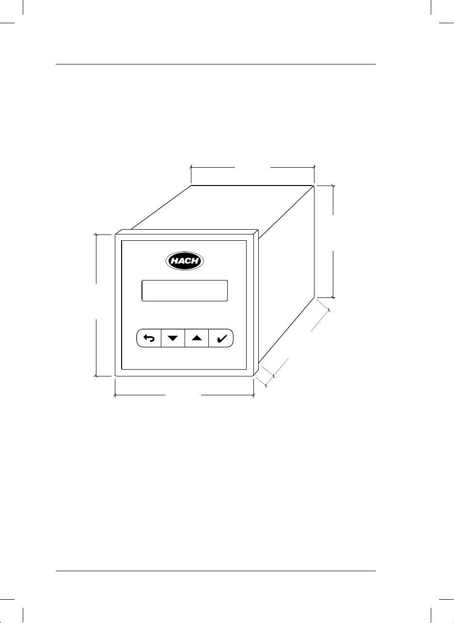
1. Technical specifications
1.1. Dimensions
si627 P
3.8 in
96 mm
90 mm
3.5 in
3.5 in
90 mm
80 mm
3.1 in
96 mm
3.8 in
4
si627 P_HACH_LANGE_Ed.0510.indd ANG:4si627 P_HACH_LANGE_Ed.0510.indd ANG:4 20/5/10 10:50:4220/5/10 10:50:42
7 mm
0.3 in
Page 9
2. General information
As a result of constant improvements to our products sometimes differences may exist between this manual
and the instructions supplied with the instrument.
ENGLISH
2.1. Safety information
Please, read carefully this information before installing and using the instrument !
Pay attention to all danger and caution statements.
2.1.1. Use of hazard information
DANGER
Indicates a potentially or imminently hazardous situation that, if not avoided, will result in death
or serious injury.
WARNING
Indicates a potentially or imminently hazardous situation that, if not avoided, may result in death
or serious injury.
CAUTION
Indicates a potentially hazardous situation that, if not avoided, may result in minor or moderate injury.
Important note
Indicates a situation that, if not avoided, could lead to damage to the instrument. Important information that requires special emphasis.
Note
Information that supplements points in the main text.
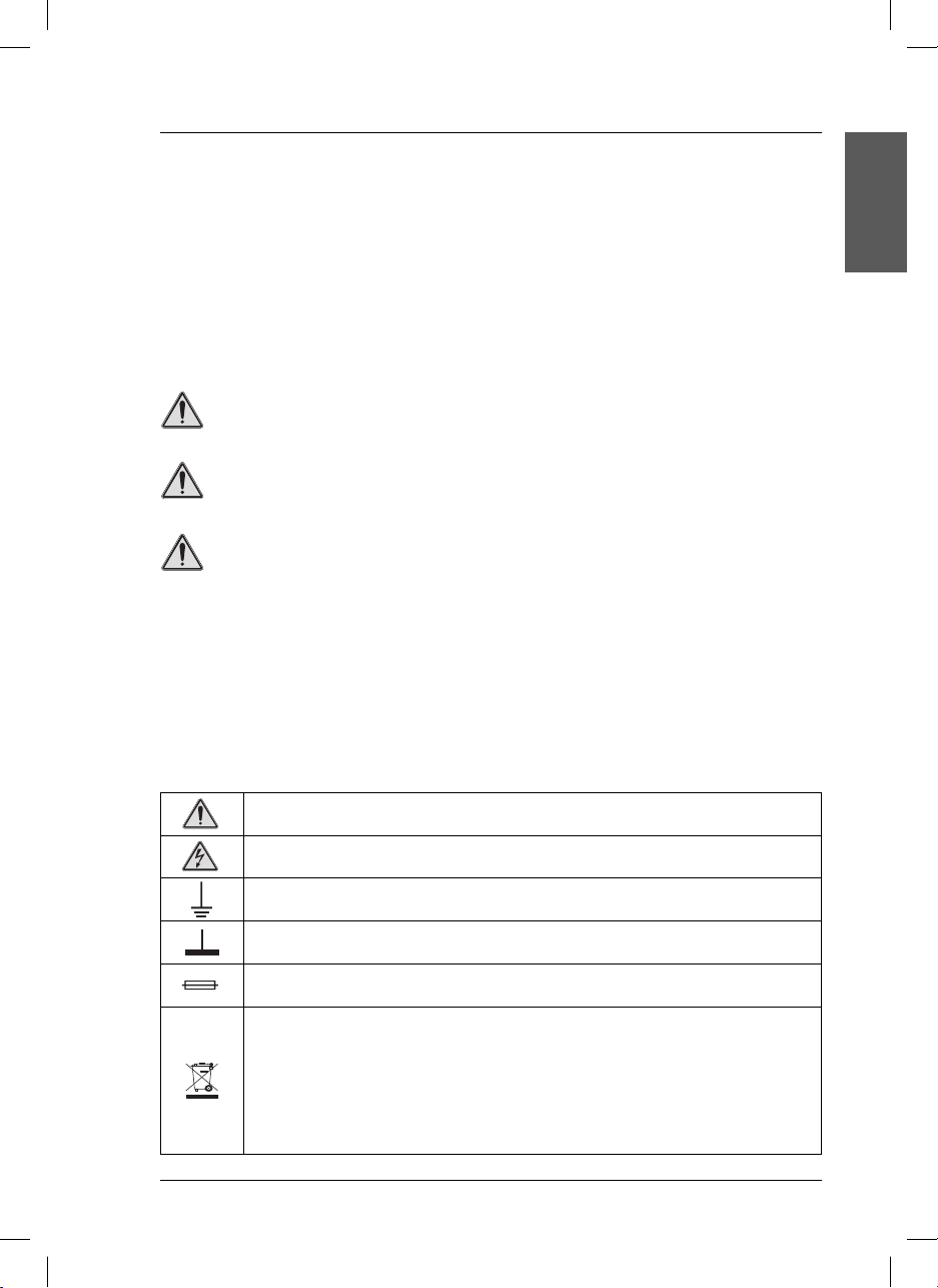
Precautionary labels
Read carefully all labels and tags attached to the instrument.
This symbol references the instruction manual for operation or safety information.
This symbol indicates that a risk of electrical shock or electrocution exists.
This symbol indicates the connection for Protective Earth.
This symbol indicates ground connection.
This symbol identifies a fuse.
Electrical equipment marked with this symbol may not be disposed of in European public disposal systems after 12 August of 2005. In conformity with European local and national regulations (EU Directive
2002/96/EC), European electrical equipment users must now return old or end-of life equipment to the
Producer for disposal at no charge to the user.
Note: For return for recycling, please contact the equipment producer or supplier for instructions on how
to return end-of-life equipment, producer-supplied electrical accessories, and all auxiliary items for proper
disposal.
5
si627 P_HACH_LANGE_Ed.0510.indd ANG:5si627 P_HACH_LANGE_Ed.0510.indd ANG:5 20/5/10 10:50:4220/5/10 10:50:42
Page 10

2. General information
DANGER
• Remember that the voltage across accessible
parts of the open instrument, may be dangerous
to life. Do not open the instrument when it is
connected to the power supply, there are areas
whose voltage could cause death.
• Always disconnect power to the instrument
before it is opened.
• Repair or adjustment of an opened instrument
under voltage shall be carried out only by
a qualified technician who is aware of the
hazards involved.
• Never work in an environment subject to
explosion hazards. The housing of the
instrument is not gas tight.
• The Company will not be responsible for any
physical damage caused by non authorised
work or manipulation.
• It is the responsibility of whoever uses this
instrument to consult and establish appropriate
safety and health practices and determine the
applicability of regulatory limitations prior to use.
• Before connecting the instrument to a power
supply unit, make sure that the mains voltage
lies within the range:
230 or 24 V AC ±10%, 45-65 Hz (standard
version).
115 V AC ±10%, 45-65 Hz (under demand).
Important notes
• Read carefully the manual of the instrument.
• Avoid direct sunlight over the instrument.
• Exclude the following environmental influences:
- vibrations
- atmospheric humidity higher than 80 %
- corrosive gases present
- temperature < 0 °C, or > 50 °C (< 32 °F, or >
122 °F).
- powerful electric and magnetic fields.
• Only use original accessories and spare parts.
• Have the instrument serviced only by the
Company Service.
2.2. General product information
Proper use
The si627 P is used for pH or redox potential and temperature measurement in the chemical industry, food
process and waste-water treatment.
2.3. Items supplied si627 P
• Instrument (with strips for connections).
• BNC connector.
• Clamps to fix to the panel.
• User manual.
6
si627 P_HACH_LANGE_Ed.0510.indd ANG:6si627 P_HACH_LANGE_Ed.0510.indd ANG:6 20/5/10 10:50:4420/5/10 10:50:44
Page 11

3. Installation
3.1. si627 P
DANGER
Only qualified personnel should conduct the tasks described in this section of the manual.
ENGLISH
3.1.1. Assembly
For the si627 P mounting a drill hole is required according to the diagram.
92 mm
3.7 in
3.7 in
92 mm
After putting the instrument in the panel, it must be fitted using two clamps as indicated in the figure.
21 mm
0.8 in
Drill hole
Panel
80 mm
3.1 in
7 mm
0.3 in
BNC connector
for electrode
Plug-in screw connector Clamp to fix to the panel
si627 P_HACH_LANGE_Ed.0510.indd ANG:7si627 P_HACH_LANGE_Ed.0510.indd ANG:7 20/5/10 10:50:4420/5/10 10:50:44
Side view
7
Page 12
3. Installation
When making any wiring connections to the instrument, any warnings and notes found throughout the
manual must be adhered to. For more safety information see “Safety information” on page 5.
DANGER
Always disconnect power to the instrument when making any electrical connections.
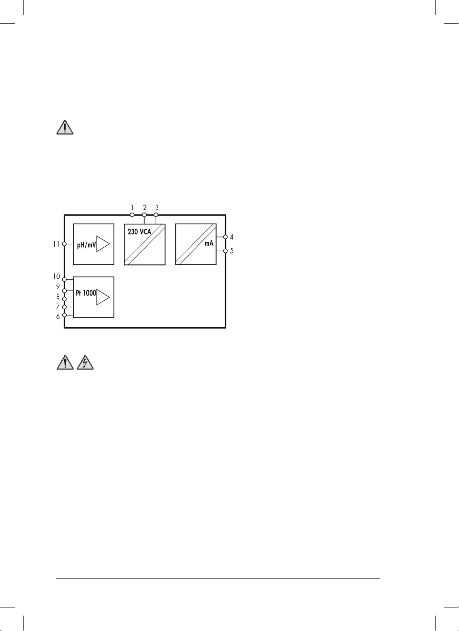
3.1.2. Connections
System functions
1 Ground connection.
See Important notes (page 9).
2,3 Power supply 230 VAC ± 10%.
(24 or 115 VAC under demand).
4,5 Current output 4-20 mA (pH or mV).
6...9 Temperature probe input.
10 Shield for temperature probe.
11 pH or redox electrode input.
High-voltage wiring for the instrument is protected by a protective casing. The protective casing
DANGER
must remain in place unless a qualified installation technician is installing wiring for power.
8
si627 P_HACH_LANGE_Ed.0510.indd ANG:8si627 P_HACH_LANGE_Ed.0510.indd ANG:8 20/5/10 10:50:4420/5/10 10:50:44
Page 13
3. Installation
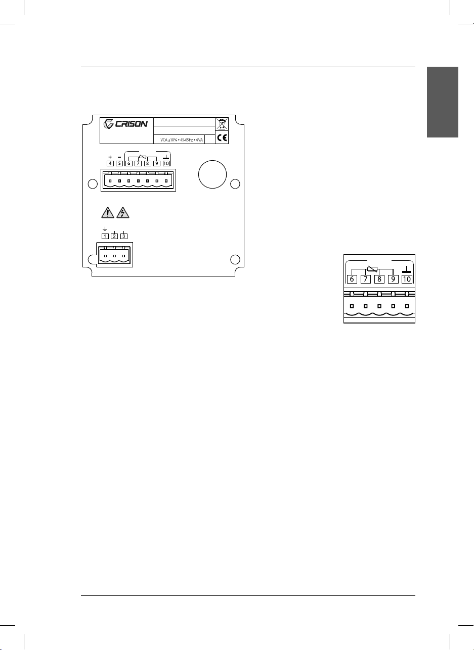
Terminal assignment (rear panel)
CRISON INSTRUMENTS, S.A.
E-08328 ALELLA - Barcelona
Made in Spain
4-20 mA Pt 1000
VCA
Transmitter si627 P
S/N:
ELECTRODE
IP 54
pH / mV
Important notes:
ENGLISH
• The si627 P does not require ground connection (terminal 1).
• In environments with interference problems it
is recommended to connect the instrument to
ground in terminal 1.
It is also recommended to use shielding cable,
both for the electrode signal (triaxial cable) and
the temperature probe.
The external shield of the triaxial cable and the
probe cable must be connected to terminal 10.
• If the temperature probe has a 2-wire cable instead of a 4-wire, fit
a jumper between ter-
Pt 1000
minals 6 and 7 and
another one between
8 and 9, as indicated
in the scheme.
9
si627 P_HACH_LANGE_Ed.0510.indd ANG:9si627 P_HACH_LANGE_Ed.0510.indd ANG:9 20/5/10 10:50:4520/5/10 10:50:45
Page 14
3. Installation
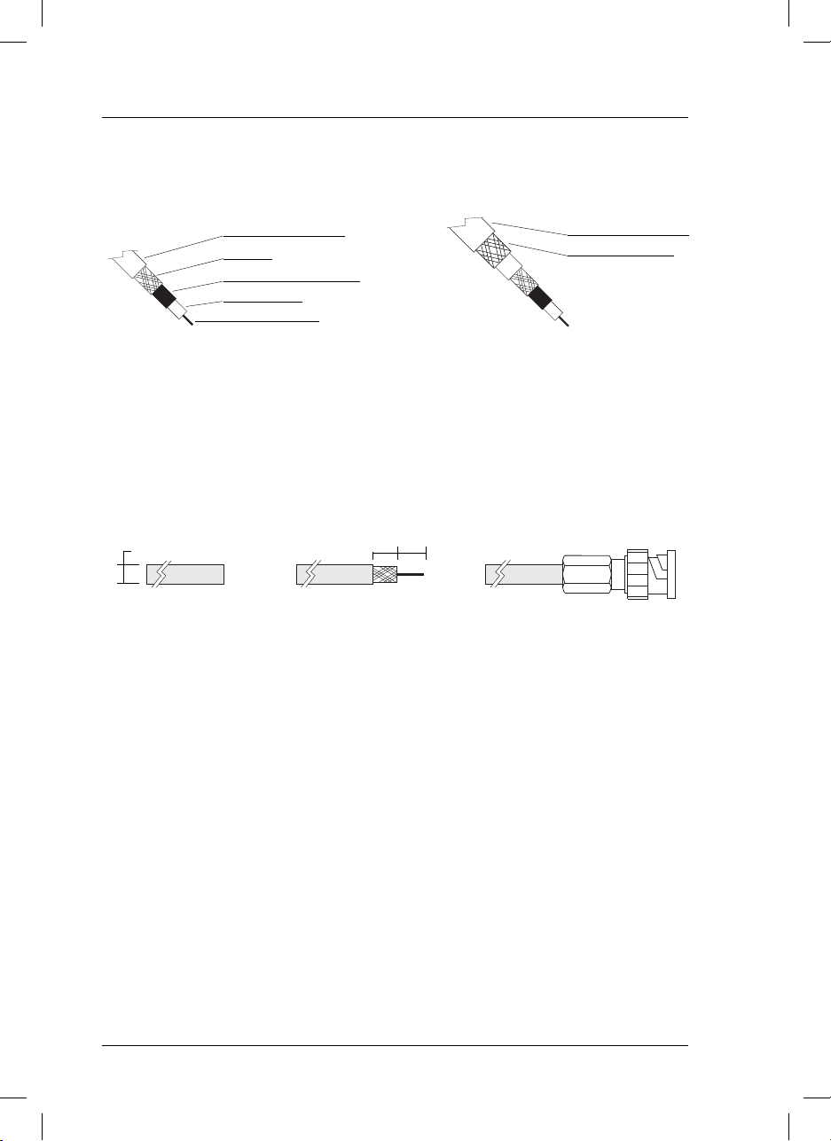
3.2. Electrode cable
Coaxial cable
PVC protector Ø 5 mm.
Shielding
Plastic conductor (black).
PE insulation.
Triaxial cable
PVC protector Ø 7 mm.
Additional shielding.
(See Important notes
page 9).
Inner conductor.
Installation of BNC connector to the cable
The instrument is supplied with a BNC connector, to be screwed directly (without weldings) to the coaxial
cable. To assemble it, the cable must be prepared and the connector screwed (see diagram below).
7 mm
5 mm
Ø
0,2 in
0,3 in
7 mm
0,3 in
Coaxial cable Cable preparation Cable with connector already screwed
Using a triaxial cable the connector is assemblied in the same way as with the coaxial cable, leaving
the “additional” shielding and the outer protector out of the connector. The additional shielding must be
connected to ground.
10
si627 P_HACH_LANGE_Ed.0510.indd ANG:10si627 P_HACH_LANGE_Ed.0510.indd ANG:10 20/5/10 10:50:4520/5/10 10:50:45
Page 15
4. Operation
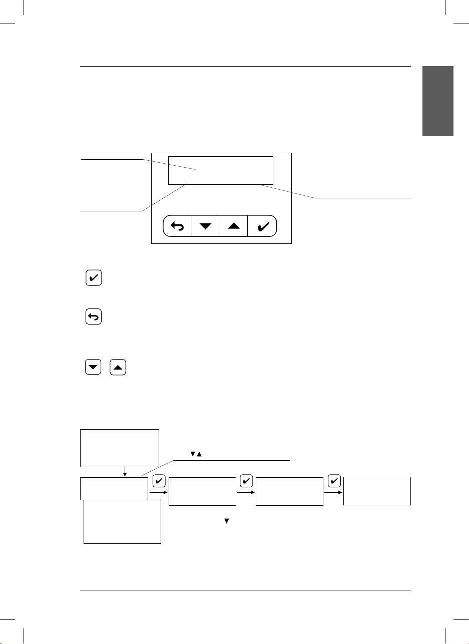
4.1. Description
Display
si627 P have an alphanumeric display that explains itself. One of the most significant screens is described below as an example:
Measured value.
ENGLISH
MEASURE
pH 7.34 25.2 °C
Sample temperature
Measuring unit.
Resolution:
1 °C manual selection.
0.1°C measuring with Pt1000.
Teclas
ENTER.
• Horizontal movements to move forward in the “diagram”.
• Acceptance of numerical values.
ESCAPE.
• Horizontal movements to move back in the “diagram”.
• Vertical movements to move back in the “diagram”.
• To erase numerical values.
• Modification of numerical values.
• Cursor “>” movements on the screen.
4.2. Setting-up
Connect the si627 P to mains. At power up the first time only the following screens will appear:
si627_P
V1.0
IDIOMA >Español
Italiano
Français
English
Deutsch
Português
Instrument is already measuring pH, with the following factory settings::
• Current output: 4 mA = pH 0, 20 mA = pH 14.
To modify this configuration see pages 13 and 14.
si627 P_HACH_LANGE_Ed.0510.indd ANG:11si627 P_HACH_LANGE_Ed.0510.indd ANG:11 20/5/10 10:50:4520/5/10 10:50:45
Possibility to select other language
with keys.
MEASURE : >pH
mV MEASURE pH & °C
Attention. Possibility to
change to mV with
key.
MEASURE
PH 7.34 25.2 °C
11
Page 16
4. Operation
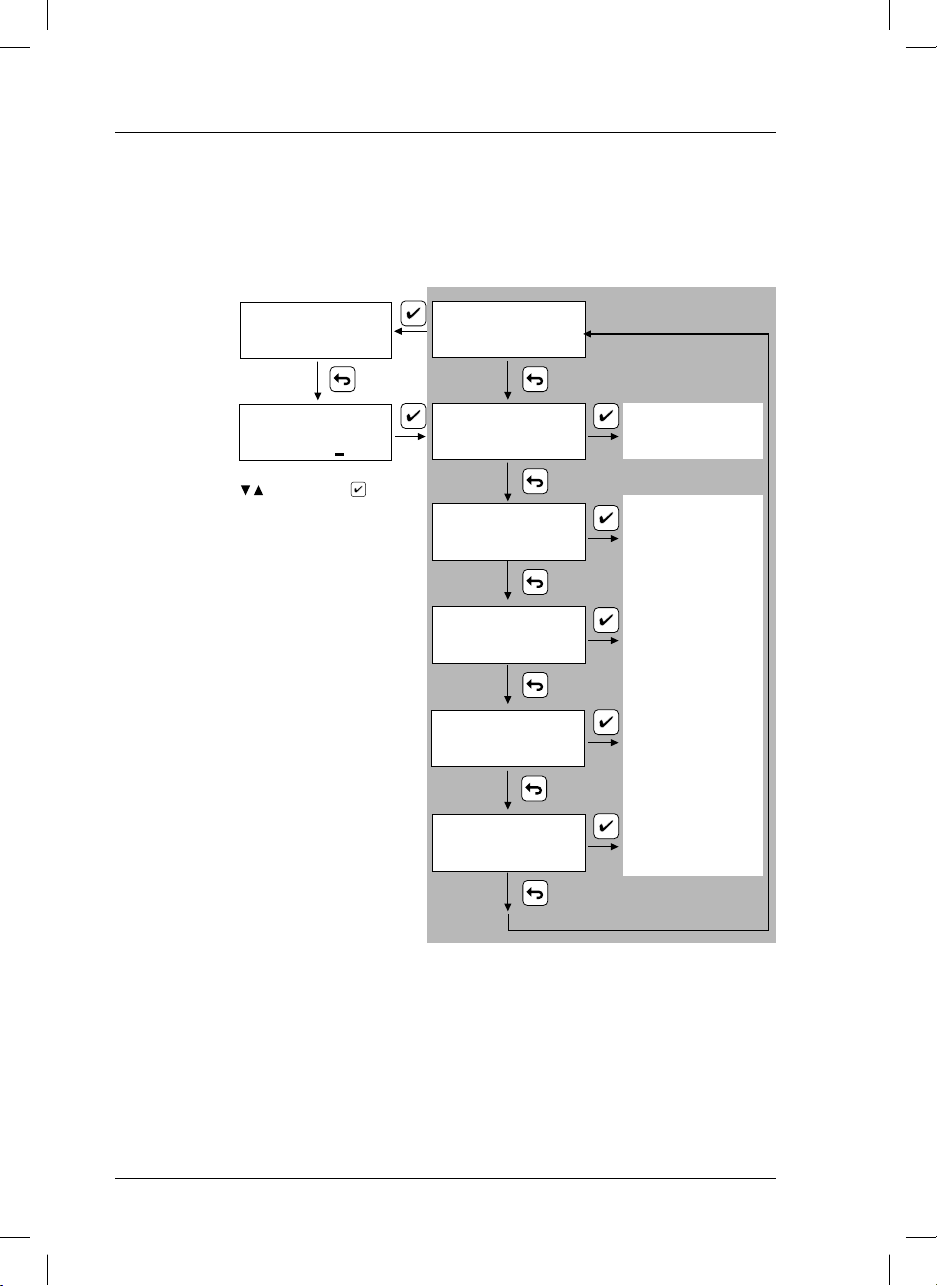
4.3. Quick guide
This page shows the instrument’s operation by blocks. It is intended to provide a quick idea about all the
instrument’s capabilities and how to gain access to them.
MEASURE
pH 7.34 25.2 °C
MEASURE pH & °C
Security access
code.
It limits the access to calibration or programming of the ins trument by non au-
CODE 000
Vary the underlined digit with
and accept with .
Authorised code = 100.
CALIBRATE
TYPE OF MEASURE
thorised people.
When the “Code” screen has been shown for
more than 30 sec. the instrument will automatically return to MEASURE.
OUTPUT 4-20 mA
LANGUAGE
See “calibration“
(page 16)
See “programming ...”
(pages 13-14)
HOLD
Instrument in hold state.
When being in the grey zone, the instrument is in hold state:
• According to the configuration the current output is frozen at 21 mA or at the mA corresponding
to the last measured value.
To quit the hold state it is necessary to return to MEASURE. The Current output 4 to 20 and the Relays
will activate in 10 sec.
12
si627 P_HACH_LANGE_Ed.0510.indd ANG:12si627 P_HACH_LANGE_Ed.0510.indd ANG:12 20/5/10 10:50:4620/5/10 10:50:46
Page 17
4. Operation
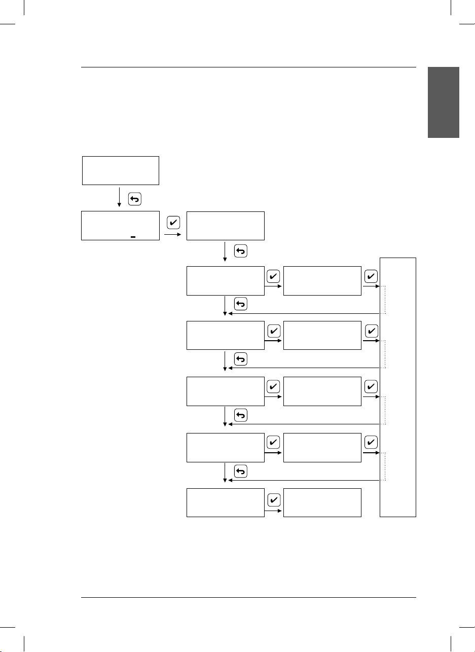
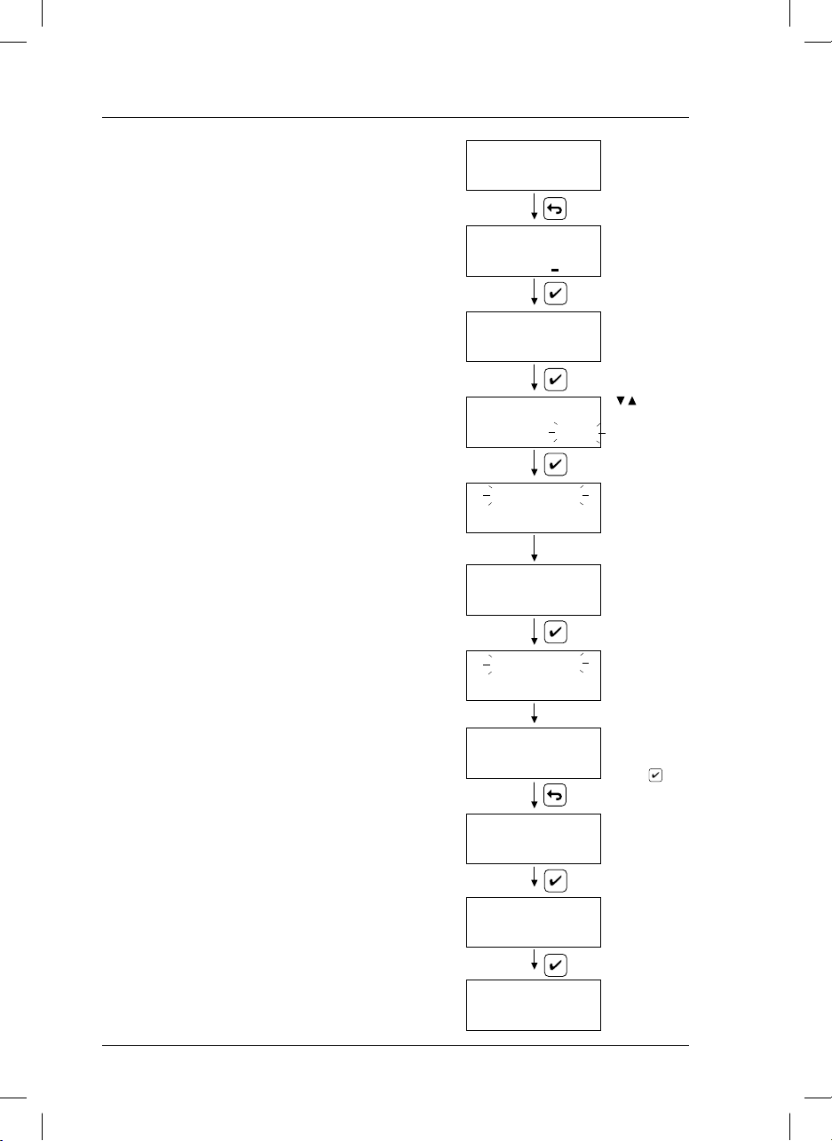
4.4. Programming to measure pH
This instrument is supplied programmed as a pH transmitter-controller with the configuration indicated
in the Setting up, at the end of page 11.
To modify the default configuration and adapt it to specific applications follow the diagram below.
MEASURE
pH 7.34 25.2 °C
CODE
000
Introduce the code 100
CALIBRATE
ENGLISH
TYPE OF MEASURE
Output current.
Selection of pH values corresponding to 4 mA and 20 mA.
Selectable values between
pH 0.0 and 14.0.
Hold.
Selection of the current output
when the instrument is in hold,
fixed at 21 mA or equivalent to
the last value
Language.
Selection of the working
language: English, German,
Spanish, French, Italian or
Portuguese.
MEASURE pH & °C
OUTPUT 4-20 mA
HOLD
LANGUAGE
UNITS: > pH
mV
4 mA 20 mA
pH: 0.0 pH: 14.0
> 21 mA
LAST
Language > Español
Italiano
MEASURE
pH 7.34 25.2 °C
STORING DATA
13
si627 P_HACH_LANGE_Ed.0510.indd ANG:13si627 P_HACH_LANGE_Ed.0510.indd ANG:13 20/5/10 10:50:4620/5/10 10:50:46
Page 18
4. Operation
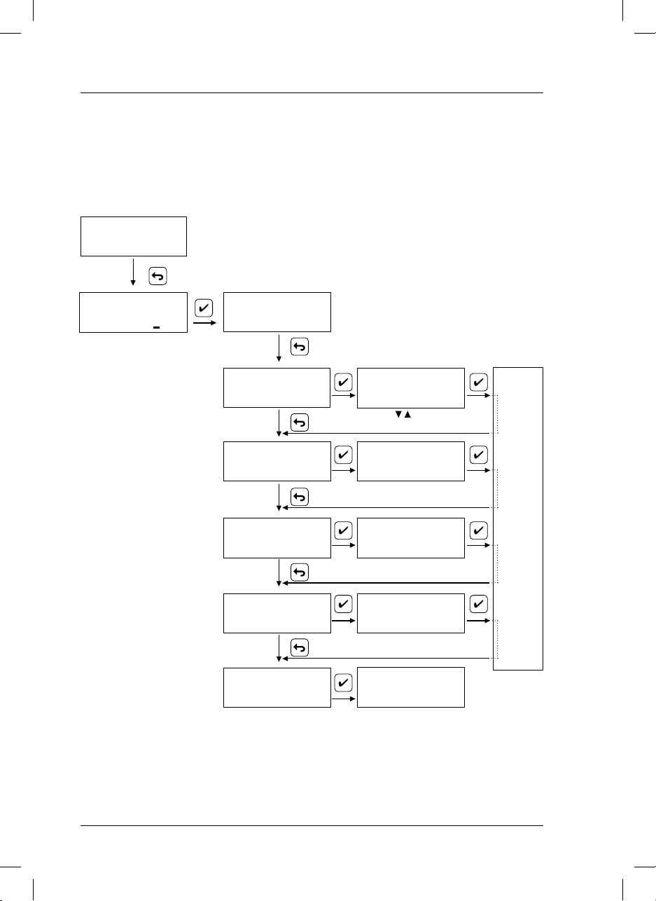
4.5. Programming to measure ORP (redox). mV range
The instrument is supplied programmed to measure pH. To change the measuring unit (pH) to mV go to Settingup, after selecting the language, see page 12, or follow the diagram below until TYPE OF MEASURE.
MEASURE
pH 7.34 25.2 °C
CODE
000
Introduce the code 100
Output current.
Selection of mV values corresponding to 4 mA and 20 mA.
Selectable values between
± 1500 mV.
Hold.
Selection of the current output
when the instrument is in hold,
fixed at 21 mA or equivalent to
the last value
Language.
Selection of the working language:
English, German, Spanish, French,
Italian or Portuguese.
CALIBRATE
TYPE OF MEASURE
OUTPUT 4-20 mA
HOLD
LANGUAGE
MEASURE pH & °C
UNITS
: pH
> mV
Variar con
4 mA 20 mA
-500 mV +500 mV
> 21 mA
LAST
Language > Español
Italiano
MEASURE
pH 7.34 25.2 °C
STORING DATA
14
si627 P_HACH_LANGE_Ed.0510.indd ANG:14si627 P_HACH_LANGE_Ed.0510.indd ANG:14 20/5/10 10:50:4720/5/10 10:50:47
Page 19
4. Operation
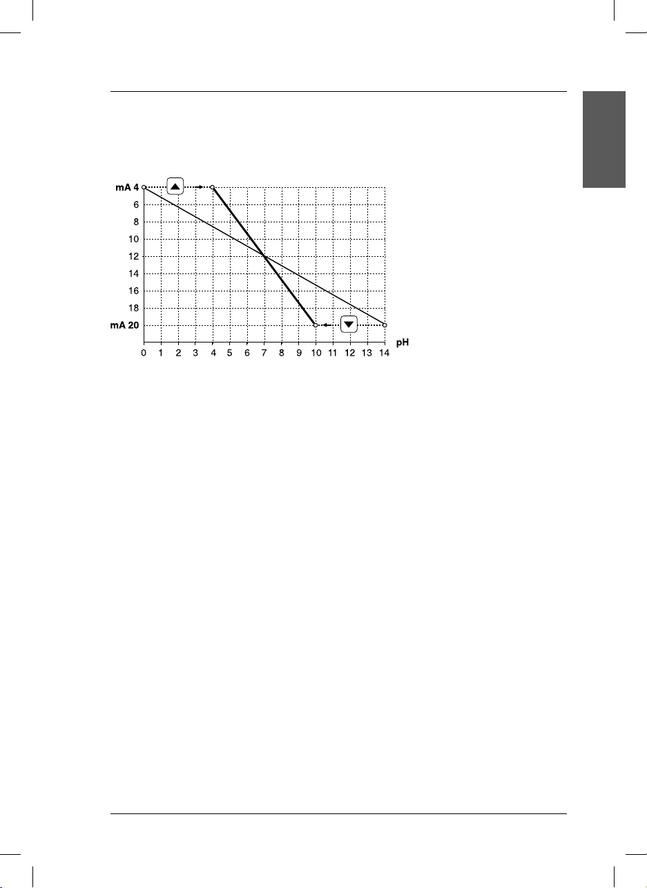
4.6. Operation of 4 to 20 outputs and Relays
Current output 4 to 20 mA depending on the pH
a b
a = Factory default values
b = Example of values user-programmed
The analogic output offers 3 levels of different currents:
• 4 to 20 mA for measurement signal (pH or mV).
• 21 mA frozen, or the last mA value measured, when the instrument is in Hold state.
• 22 mA frozen, with the message OUT OF RANGE on display during 1 minute or more. Alarm.
ENGLISH
15
si627 P_HACH_LANGE_Ed.0510.indd ANG:15si627 P_HACH_LANGE_Ed.0510.indd ANG:15 20/5/10 10:50:4820/5/10 10:50:48
Page 20
4. Operation
4.7. Calibration of pH electrode
To measure pH correctly, the electrode and instrument set
MEASURE
pH 7.34 25.2 °C
needs to be calibrated regularly with buffer solutions.
The instrument is capable of one-, two- and three-point calibration. The calibration parameters are stored in the memory until a new calibration is performed.
CODE 000
If an anomaly occurs during calibration an error message
will appear on-screen (see page 19).
One-point calibration
CALIBRATE
This form of calibration is acceptable when pH values
around that of the buffer used are being measured.
One-point calibration only corrects the asymmetry potential
of the electrode.
INSERT 1 st BUFFER
25°C
Two-point calibration
This is the most common type of calibration. We recommend pH 7 for the first buffer, and pH 4 or 9 for the second,
depending on whether you will be working in the acid or
CALIBRATING
pH 7.02 19°C
alkaline region.
In addition to asymmetry potential, calibration with two
buffers also compensates the electrode slope or sensitivity
loss.
INSERT 2 nd BUFFER
Three-point calibration
This type of calibration is recommended when measurements
are made across the entire pH scale. It is also used when a
great deal of accuracy is required in a certain region.
CALIBRATING
pH 4.00 19°C
For the first point pH 7 is recommended. For the second and
third points, two of the remaining values must be chosen (pH
2.00, 4.01, 9.21, 10.90, at 25˚C).
Three-point calibration compensates the asymmetry of the
INSERT 3d BUFFER
electrode and its sensitivity in acid and alkaline regions.
During calibraTIOn instrument is in hold state:
Notes:
• Current output is frozen at 21 mA or at last value.
To quit the
Press ESC to quit the calibration, from any screen, without
storing data.
For practical reasons, CRISON recommeds to select
temperature manually during calibraTIOn, even if you have
an ATC probe connected (Pt 1000)
hold state it is necessary to return to mEASURE.
59.26 mV/pH
ASYMMETRY POT.
0 mV
CALIBRATION OK
SLOPE
Introduce the
code 100
The buffer
temperature
can be introduced by the
, keys.
The display
shifts automatically when
the reading is
stable.
Press
to perform a
3-point calibration.
16
si627 P_HACH_LANGE_Ed.0510.indd ANG:16si627 P_HACH_LANGE_Ed.0510.indd ANG:16 20/5/10 10:50:4820/5/10 10:50:48
Page 21
4. Operation
4.8. Recognized Buffers
Table of values according to temperature.
Values stored in the si627 P
°C pH
0 2.01 4.01 7.12 9.52 11.45
10 2.01 4.00 7.06 9.38 11.20
20 2.00 4.00 7.02 9.26 11.00
25 2.00 4.01 7.00 9.21 10.90
30 2.00 4.01 6.99 9.16 10.81
40 2.00 4.03 6.97 9.06 10.64
50 2.00 4.06 6.97 8.99 10.48
60 2.00 4.10 6.98 8.93 10.23
70 2.01 4.16 7.00 8.88 10.19
80 2.01 4.22 7.04 8.83 10.06
90 2.01 4.30 7.09 8.79 9.93
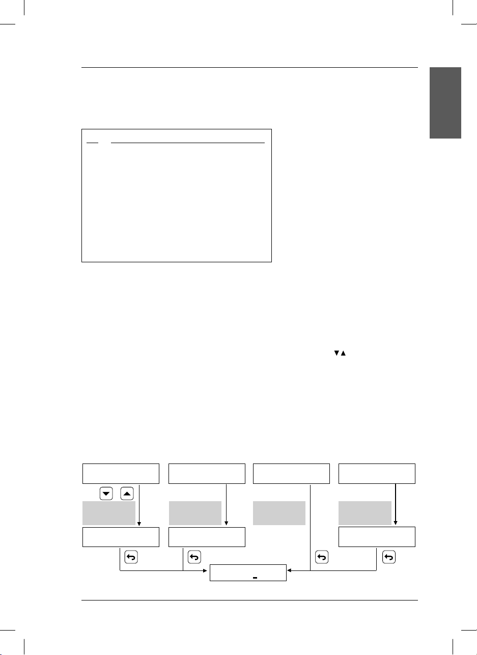
4.9. Measurement
pH and temperature measurement
The pH value and the temperature in °C appear simultaneously on the display. The instrument is usually
measuring pH (see page 13).
The temperature is measured when an A.T.C. Pt 1000 is connected. Otherwise, it is necessary to inform
the instrument about the temperature of the measured solution using the keys
.
ENGLISH
ORP (redox) measurement. mV range
To measure redox potential the instrument must be programmed to measure mV (see page 14).
The temperature is measured when an A.T.C. Pt 1000 is connected.
The redox potential (mV) of the solutions is affected by temperature. Nevertheless the instrument does not
carry out any compensation. Hence it is impossible to introduce the process temperature manually.
pH measurement... mV measurement...
...without A.T.C. Pt 1000 ...with A.T.C. Pt 1000 ...without A.T.C. Pt 1000 ...with A.T.C. Pt 1000
MEASURE
pH 7.34 25 °C
Temperature
selected
manually
MEASURE
pH 7.34 17 °C
MEASURE
pH 7.34 25.2 °C
Temperature
measured
automatically
MEASURE
pH 7.34 25.1 °C
MEASURE
375 mV
Temperature
not indicated
CODE 000
si627 P_HACH_LANGE_Ed.0510.indd ANG:17si627 P_HACH_LANGE_Ed.0510.indd ANG:17 20/5/10 10:50:4820/5/10 10:50:48
MEASURE
375 mV 21.3 °C
Temperature
totally
independent
MEASURE
375 mV 21.4 °C
17
Page 22

5. Maintenance
5.1. Clean the measuring instrument and accessories
Important note: Never use cleaning such as turpentine, acetone or similar products to clean the instrument
including the display and accessories.
Only clean the housing and accessories using a soft, damp cloth. Mild soap solution may also be used. Dry
the cleaned parts carefully with a soft cotton cloth.
CAUTION
When using chemicals or solvents, comply with the instructions of the producer and the general
safety rules.
18
si627 P_HACH_LANGE_Ed.0510.indd ANG:18si627 P_HACH_LANGE_Ed.0510.indd ANG:18 20/5/10 10:50:4820/5/10 10:50:48
Page 23
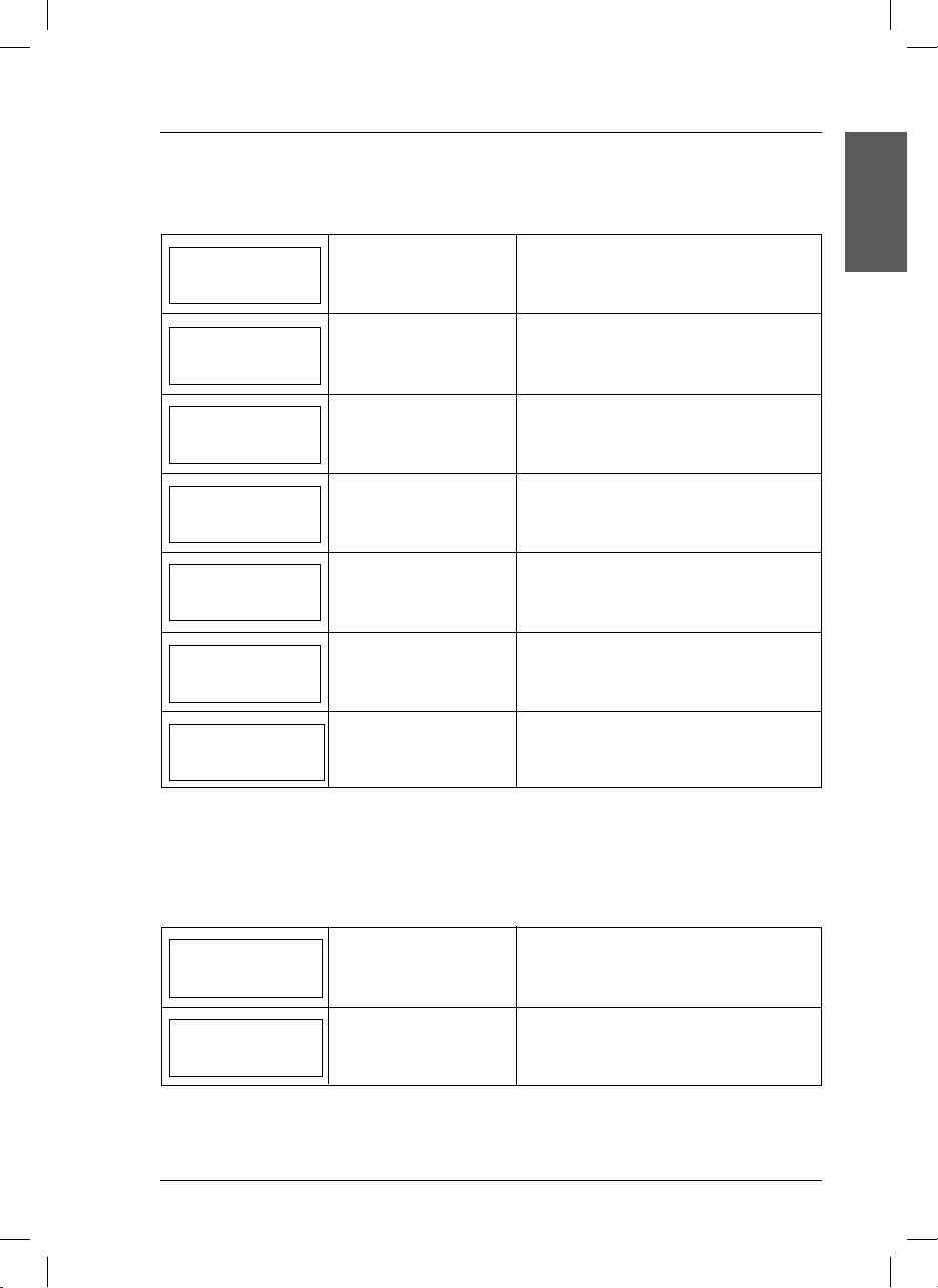
6. Error messages
During calibration
On display Problem Possible causes
Asymmetry Potential
> 60 mV
Electrode asymmetry
potential > 60 mV.
Electrode “worn out”.
Buffer solutions contaminated.
ENGLISH
Sensitivity
< 85 %
Sensitivity
> 103 %
Buffer solutions at
different temperature
Unstable reading
more than 1 min
SAME BUFFER
SOLUTIONS
UNKNOWN
BUFFER SOLUTION
Electrode slope < 85 % of
theoretical value.
Electrode slope > 103 % of
theoretical value.
Buffers temperature.
Unstable reading for more
than 60 seconds.
1st and 2nd buffer solutions
are the same.
Incorrect buffer solution.
Electrode “worn out”.
Buffer solutions contaminated.
Electrode “worn out”.
Buffer solutions contaminated.
The temperature difference between both buffer
solutions used in calibration is > 3 °C.
Press ESC to quit.
Electrode defective or dirty, see miscellaneous solutions. Variation of buffer solution temperature.
(i.e. when stored previously in the refrigerator).
Same standard was used for both calibration steps.
Electrode is broken or cable defective.
Press ESC to quit.
Same standard was used for both calibration steps.
Electrode is broken or cable defective.
Press ESC to quit.
Other messages
On display Problem Possible causes
Measured value out of
OUT OF RANGE
°C OUT OF RANGE
si627 P_HACH_LANGE_Ed.0510.indd ANG:19si627 P_HACH_LANGE_Ed.0510.indd ANG:19 20/5/10 10:50:4920/5/10 10:50:49
range.
Measured temperature out
of range.
pH value < -2 or > 16, mV < –1500 or > 1500.
The current output will be frozen at 22 mA.
(Alarm).
Pt 1000 broken or temperature < –20 or >
. The current output will be frozen at 22
150°C
mA. (Alarm)
19
Page 24

7. Replacement parts
P/N Description
LZU1004.99 Clamps to fix si629 P (only panel mount).
LZU9106.99 BNC connector, straight, for coaxial cable Ø 5 (manual assembly, without special tools).
LZU9188.99 BNC Connector, L-shaped, for coaxial cable (manual assembly, without special tools).
LZU1003.99 Coaxial cable with AS9 connector, 3 m.
LZU1005.99 Coaxial cable with AS9 connector, 5 m.
LZU1010.99 Coaxial cable with AS9 connector, 10 m.
LZU1015.99 Coaxial cable with AS9 connector, 15 m.
LZU1020.99 Coaxial cable with AS9 connector, 20 m.
LZU1025.99 Coaxial cable with AS9 connector, 25 m.
LZW9463.99 pH buffer solution 4.01, with certificate of analysis, 250 ml flask.
LZW9466.99 pH buffer solution 4.01, with certificate of analysis, 1000 ml flask.
LZW9464.98 pH buffer solution 7.00, with certificate of analysis, 250 ml flask.
LZW9467.98 pH buffer solution 7.00, with certificate of analysis, 1000 ml flask.
LZW9465.99 pH buffer solution 9.21, with certificate of analysis, 250 ml flask.
LZW9468.99 pH buffer solution 9.21, with certificate of analysis, 1000 ml flask.
LZW9400.99 Standard redox solution of 220 mV, 250 ml flask.
LZW9401.99 Standard redox solution of 220 mV, 1000 ml flask.
For electrodes please ask for specific brochure.
20
si627 P_HACH_LANGE_Ed.0510.indd ANG:20si627 P_HACH_LANGE_Ed.0510.indd ANG:20 20/5/10 10:50:4920/5/10 10:50:49
Page 25

8. Warranty and liability
The manufacturer warrants that the product supplied is free of material and manufacturing defects and
undertakes the obligation to repair or replace any defective parts at zero cost.
The warranty period for instruments is 24 months. If a service contract is taken out within 6 months of purchase, the warranty period is extended to 60 months.
With the exclusion of the further claims, the supplier is liable for defects including the lack of assured properties as follows: all those parts that, within the warranty period calculated from the day of the transfer of
risk, can be demonstrated to have become unusable or that can only be used with significant limitations
due to a situation present prior to the transfer of risk, in particular due to incorrect design, poor materials or
inadequate finish will be improved or replaced, at the supplier’s discretion. The identification of such defects
must be notified to the supplier in writing without delay, however at the latest 7 days after the identification
of the fault. If the customer fails to notify the supplier, the product is considered approved despite the defect.
Further liability for any direct or indirect damages is not accepted.
If instrument-specific maintenance and servicing work defined by the supplier is to be performed within the
warranty period by the customer (maintenance) or by the supplier (servicing) and these requirements are not
met, claims for damages due to the failure to comply with the requirements are rendered void.
Any further claims, in particular claims for consequential damages cannot be made.
Consumables and damage caused by improper handling, poor installation or incorrect use are excluded
from this clause.
The manufacturer process instruments are of proven reliability in many applications and are therefore often
used in automatic control loops to provide the most economical possible operation of the related process.
To avoid or limit consequential damage, it is therefore recommended to design the control loop such that
a malfunction in an instrument results in an automatic change over to the backup control system; this is the
safest operating state for the environment and the process.
ENGLISH
21
si627 P_HACH_LANGE_Ed.0510.indd ANG:21si627 P_HACH_LANGE_Ed.0510.indd ANG:21 20/5/10 10:50:4920/5/10 10:50:49
Page 26

si627 P_HACH_LANGE_Ed.0510.indd ANG:22si627 P_HACH_LANGE_Ed.0510.indd ANG:22 20/5/10 10:50:4920/5/10 10:50:49
Page 27

Inhalt
1. Technische Daten . . . . . . . . . . . . . . . . . . . . . . . . . . 3
1.1. Abmessungen
2. Allgemeine Informationen . . . . . . . . . . . . 5
2.1. Sicherheitshinweise
2.1.1. Bedeutung von Gefahrenhinweisen
2.2. Allgemeine Produktinformationen
2.3. Inhalt
. . . . . . . . . . . . . . . . . . . . . . . . . 4
. . . . . . . . . . . . . . . . . . . . . 5
5
. . . . . . . . . 6
. . . . . . . . . . . . . . . . . . . . . . . . 6
3. Installation
3.1. si627 P
3.1.1. Montage
3.1.2. Anschlüsse
3.2. Elektrodenkabel
4. Bedienung und Funktion
4.1. Beschreibung
4.2. Inbetriebnahme
4.3. Kurzanleitung
4.4. Programmierung für die pH-Messung
4.5. Programmierung für die ORP-Messung
4.6. Betrieb des Ausgangs 4 bis 20 mA
4.7. Kalibrierung der pH-Elektrode
4.8.
4.9. Messung
5. Wartung
5.1. Reinigung des Geräts und des Zubehörs
6. Fehlermeldungen
7. Ersatzteile
8. Gewährleistung und Haftung
. . . . . . . . . . . . . . . . . . . . . . . . . . . . . . . . 7
. . . . . . . . . . . . . . . . . . . . . . . . . . . . . . . 7
. . . . . . . . . . . . . . . . . . . . . . . . 7
. . . . . . . . . . . . . . . . . . . . . . . 8
. . . . . . . . . . . . . . . . . . . . . . . . 10
. . . . . . . . . . . . . . . . . . 11
. . . . . . . . . . . . . . . . . . . . . . . . . . 11
. . . . . . . . . . . . . . . . . . . . . . . . 11
. . . . . . . . . . . . . . . . . . . . . . . . . . 12
. . . . . 13
. . . . 14
. . . . . . 15
. . . . . . . . . . . . 16
Geeignete pH-Puffer . . . . . . . . . . . . . . . . . . . . 17
. . . . . . . . . . . . . . . . . . . . . . . . . . . . . . 17
. . . . . . . . . . . . . . . . . . . . . . . . . . . . . . . 18
. . 18
. . . . . . . . . . . . . . . . . . . . . . . . . 19
. . . . . . . . . . . . . . . . . . . . . . . . . . . . . . . 20
. . . . . . . . . . . . 21
Kontaktdaten
DEUTSCH
1
si627 P_HACH_LANGE_Ed.0510.indd ALE:1si627 P_HACH_LANGE_Ed.0510.indd ALE:1 20/5/10 10:50:4920/5/10 10:50:49
Page 28

si627 P_HACH_LANGE_Ed.0510.indd ALE:2si627 P_HACH_LANGE_Ed.0510.indd ALE:2 20/5/10 10:50:4920/5/10 10:50:49
Page 29

1. Technische Daten
Messbereiche
pH: –2,00 bis 16,00
mV: –1500 bis 1500
°C: –20,0 bis 150,0
Messfehler
≤ 0,02 pH, ≤ 1 mV, ≤ 0,5 °C (±1 Stelle)
Reproduzierbarkeit
±0,01 pH, ±1 mV, ±0,1 °C (±1 Stelle)
Automatische Temperaturkompensation
Mit Temperatursensor (Pt 1000) oder
Dateneingabe über Tastatur
Kalibrierungsoptionen (pH)
Zugangscode (Festcode): 100
Mit 1, 2 oder 3 Puffern
Automatische Puffererkennung
Technischer pH 2,00, 4,01, 7,00, 9,21 und
10,90 (bei 25 °C).
Kriterien für die Annahme der
Kalibrierung
Steilheitsbereich: 85 bis 103 %
Asymmetriepotential: ≤ 60 mV
Sprachen
Englisch, Deutsch, Spanisch, Französisch,
Italienisch, Portugiesisch
Display
LCD, alphanumerisch, von hinten beleuchtet,
2 Zeilen zu je 16 Buchstaben
Eingänge und Ausgänge
Elektrode, BNC-Stecker
Temperatursensor, Typ Pt 1000,
Klemmleistenanschluss
Galvanisch isolierter Analogausgang
• 4 bis 20 mA für die Messung (R max.= 500 Ω)
• 21 mA oder mA-Wert entsprechend dem
letzten Messwert für den Haltemodus (Hold)
• 22 mA für Alarm
Maximale Kabellänge
≤ 25 m
Spannungsversorgung
230 oder 24 VAC ±10 %, 45–65 Hz,
Standardausführungen
(115 VAC auf Anfrage)
Leistungsaufnahme: 4 VA
Schutzklasse II
Überspannungskategorie II
EG-Richtlinien
Gemäß Niederspannungsrichtlinie 2006/95/EG
Elektromagnetische Verträglichkeit gemäß
Richtlinie 2004/108/EG
Umgebungsbedingungen
Betriebstemperatur:
0 bis 50 °C (32 bis 122 °F)
Lagertemperatur:
-20 bis 65 °C (-4 bis 149 °F)
Relative Feuchtigkeit: < 80 % (nicht kondensiert)
Max. Höhe 2.000 m bei 230 V; 3.000 m bei
24 V
Gehäuse
si627 P Noryl, frontseitiger Schutz IP54.
Brennbarkeit: FV-1
Gewicht
600 g
Abmessungen
96 x 96 x 100 mm
Garantie
Geräte: 2 Jahre
Technische Daten können jederzeit ohne Vorankündigung geändert werden.
DEUTSCH
3
si627 P_HACH_LANGE_Ed.0510.indd ALE:3si627 P_HACH_LANGE_Ed.0510.indd ALE:3 20/5/10 10:50:4920/5/10 10:50:49
Page 30
1. Technische Daten
1.1. Abmessungen
si627 P
3.8 in
96 mm
90 mm
3.5 in
3.5 in
90 mm
80 mm
3.1 in
96 mm
3.8 in
4
si627 P_HACH_LANGE_Ed.0510.indd ALE:4si627 P_HACH_LANGE_Ed.0510.indd ALE:4 20/5/10 10:50:4920/5/10 10:50:49
7 mm
0.3 in
Page 31

2. Allgemeine Informationen
Da wir unsere Geräte laufend verbessern, können Unterschiede zwischen den Informationen in dieser
Bedienungsanleitung und dem von Ihnen erworbenen Gerät nicht ausgeschlossen werden.
2.1. Sicherheitshinweise
Lesen Sie die vorliegende Bedienungsanleitung vor der Montage und Installation des Geräts vollständig
durch.
Beachten Sie alle Warnetiketten.
2.1.1. Bedeutung von Gefahrenhinweisen
GEFAHR
Weist auf eine potenzielle oder unmittelbare Gefahrensituation hin, deren Nichtbeachtung zu
ernsthaften Verletzungen oder sogar zum Tod führt.
WARNUNG
Weist auf eine potenzielle oder unmittelbare Gefahrensituation hin, deren Nichtbeachtung zu
ernsthaften Verletzungen oder sogar zum Tod führen kann.
VORSICHT
Weist auf eine mögliche Gefahrensituation hin, die zu leichten bis mittelschweren Verletzungen
führen kann.
Wichtiger Hinweis: Weist auf eine Situation hin, die zu Schäden am Gerät führen kann. Wichtige
Information, die beim Umgang mit dem Gerät besonders zu beachten ist.
Hinweis: Zusätzliche Information über den Umgang mit dem Gerät.
DEUTSCH
Warnetiketten
Beachten Sie alle am Gerät angebrachten Etiketten, Schilder und Aufkleber.
Dieses Symbol verweist auf Bedienungs- und/oder Sicherheitshinweise in der Bedienungsanleitung.
Dieses Symbol weist auf Verletzungs- oder Lebensgefahr durch einen Stromschlag hin.
Dieses Symbol bezeichnet die Anschlussstelle für die Schutzerde.
Dieses Symbol bezeichnet die Erdung.
Dieses Symbol bezeichnet die Lage der Sicherung.
Elektrogeräte, die mit diesem Symbol gekennzeichnet sind, dürfen nach dem 12. August 2005 in Europa nicht im normalen öffentlichen Abfallsystem entsorgt werden, sondern müssen gesondert gesammelt
werden. Nach den Maßgaben der EU-Richtlinie 2002/96/EG müssen Elektro- und Elektronik-Altgeräte
von den Nutzern kostenlos zur Entsorgung an den Hersteller zurückgegeben werden können.
Hinweis: Zur Rücknahme zwecks Recycling wenden Sie sich bitte an den Hersteller oder Lieferanten des
Geräts. Bitten Sie ihn um Informationen zur Rückgabe von Elektro- und Elektronik-Altgeräten, von durch
den Hersteller geliefertem Elektrozubehör und von allen Zusatzkomponenten für die ordnungsgemäße
Entsorgung.
5
si627 P_HACH_LANGE_Ed.0510.indd ALE:5si627 P_HACH_LANGE_Ed.0510.indd ALE:5 20/5/10 10:50:4920/5/10 10:50:49
Page 32

2. Allgemeine Informationen
GEFAHR
• Das Gerät darf nicht geöffnet werden, wenn es
an das Stromnetz angeschlossen ist. Hierdurch
werden spannungsführende Teile freigelegt,
deren Berührung zum Tod führen kann.
• Wenn es unbedingt nötig ist, das Gerät zu öffnen,
muss dieses zuvor von allen Spannungsquellen
getrennt werden.
• Arbeiten am Geräteinneren dürfen nur von
entsprechend geschulten Technikern durchgeführt
werden, die mit den möglichen Gefahren beim
Umgang mit dem Gerät vertraut sind.
• Das Gerät darf nicht in einer Umgebung mit
Explosionsgefahr verwendet werden. Das
Gehäuse des Geräts ist nicht gasdicht.
• Hach Company kann nicht für gesundheitliche
Schäden haftbar gemacht werden, die durch
nicht fachgerechte Arbeiten am Gerät verursacht
werden.
• Der Benutzer hat selbst für ausreichende
Vorkehrungen zum Schutz seiner Sicherheit
und seiner Gesundheit zu sorgen. Vor der
Nutzung des Geräts sind die entsprechenden
Verwendungsbeschränkungen darüber hinaus
vom Benutzer selbst zu bestimmen.
• Vor dem Anlegen von Spannung an das Gerät
ist sicherzustellen, dass diese in folgendem
Bereich liegt:
230 oder 24 VAC ±10 %, 45–65 Hz
(Standardausführungen)
115 VAC ±10 %, 45–65 Hz (auf Anfrage).
Wichtige Hinweise
• Lesen Sie die Anweisungen zum Umgang mit
dem Gerät sorgfältig durch.
• Entfernen Sie Spritzer sofort. Das Gerät ist nicht
wasserdicht.
• Folgende Beanspruchungen sind zu vermeiden:
- Erschütterungen
- atmosphärische Feuchtigkeit über 80 %
- korrosive Gase
- Temperaturen < 0 °C oder > 50 °C (< 32 °F
oder > 122 °F)
- starke magnetische und elektrische Felder
• Verwenden Sie nur Original-Ersatzteile und
-Zubehör.
• Für Geräteprüfungen ist der Technische
Kundendienst von Hach Company zuständig.
2.2. Allgemeine Produktinformationen
Bestimmungsgemäßer Gebrauch
Das si627 P wird zur Messung von pH- und Redoxwerten in Industrie und Umwelt, bei der Lebensmittelverarbeitung und für Abwasser eingesetzt.
2.3. Inhalt si627 P
• Gerät (einschließlich Klemmleisten für die Anschlüsse)
• BNC-Stecker
• Klammer zur Befestigung an der Schalttafel
• Bedienungsanleitung
6
si627 P_HACH_LANGE_Ed.0510.indd ALE:6si627 P_HACH_LANGE_Ed.0510.indd ALE:6 20/5/10 10:50:5120/5/10 10:50:51
Page 33

3. Montage und Installation
3.1. si627 P
GEFAHR
In diesem Kapitel beschriebene Arbeiten dürfen nur von qualifiziertem Fachpersonal vorgenommen werden.
3.1.1. Montage und Installation
Zur Installation des si627 P in einer Schalttafel ist eine der Zeichnung entsprechende Vorbohrung
erforderlich.
92 mm
3.7 in
DEUTSCH
3.7 in
92 mm
Bohrung
Schalttafel
Das in die Schalttafel eingesetzte Gerät wird mit zwei Klammern befestigt (s. Abbildung).
21 mm
0.8 in
80 mm
3.1 in
7 mm
0.3 in
BNC-Stecker
Elektrode
Montierte Klemmleiste Klammer zur Befestigung an
Seitenansicht
der Schalttafel
7
si627 P_HACH_LANGE_Ed.0510.indd ALE:7si627 P_HACH_LANGE_Ed.0510.indd ALE:7 20/5/10 10:50:5120/5/10 10:50:51
Page 34

3. Montage und Installation
Beim Anschließen des Geräts sind alle Sicherheitsempfehlungen in dieser Bedienungsanleitung zu beachten. Das Kapitel „Sicherheitshinweise“ auf Seite 5 der vorliegenden Bedienungsanleitung sollte unbedingt
durchgelesen werden.
GEFAHR
Beim Herstellen elektrischer Anschlüsse muss das Gerät vom Stromnetz getrennt sein.
3.1.2. Anschlüsse
Blockschaltbilder
1 Erdung.
Siehe Wichtige Hinweise auf S. 9.
2,3 Versorgung mit 230 VAC ±10 %
(24 VAC oder 115 VAC auf Anfrage)
4,5 Ausgangsstrom 4 - 20 mA
(pH oder mV).
6...9 Eingang für Temperaturfühler
10 Abschirmung des Temperaturfühlers
11 Eingang für pH- oder Redox-Elektrode
GEFAHR
Die Klemmleiste für den Netzanschluss ist durch ein Gehäuse geschützt. Dieses darf nur für die
Montage- und Installationsarbeiten durch qualifiziertes Fachpersonal entfernt werden.
8
si627 P_HACH_LANGE_Ed.0510.indd ALE:8si627 P_HACH_LANGE_Ed.0510.indd ALE:8 20/5/10 10:50:5120/5/10 10:50:51
Page 35

3. Montage und Installation
Klemmenbelegen (hintere Klemmleiste)
CRISON INSTRUMENTS, S.A.
E-08328 ALELLA - Barcelona
Made in Spain
4-20 mA Pt 1000
VCA
Transmitter si627 P
S/N:
ELECTRODE
IP 54
pH / mV
Wichtige Hinweise:
• Der si627 P-Transmitter benötigt keine Erdung
(Klemme 1).
• In Umgebungen, in denen es zu Interferenzen
kommen kann, empfiehlt es sich, das Gerät an
der Klemme 1 zu erden und das Triaxialkabel
zu verwenden; der Zusatzschirm wird an der
Klemme 1 angeschlossen.
Ist kein Erdungsanschluss verfügbar, so sollte
DEUTSCH
die Klemme 1 frei gelassen und der Zusatzschirm des Triaxialkabels an der Klemme 10
(Abschirmung für Pt 1000) angeschlossen
werden.
• Ist das Kabel des Temperaturfühlers 2-adrig
(statt 4-adrig), so ist eine Brücke zwischen
den Klemmen 6
Pt 1000
und 7 sowie
zwischen den
Klemmen 8 und
9 notwendig
(s. Plan).
9
si627 P_HACH_LANGE_Ed.0510.indd ALE:9si627 P_HACH_LANGE_Ed.0510.indd ALE:9 20/5/10 10:50:5120/5/10 10:50:51
Page 36

3. Montage und Installation
3.2. Elektrodenkabel
Koaxialkabel
PVC-Schutz, Ø 5 mm
Schirm
Leitfähiger Kunststoff (schwarz)
PE-Isolierung
Innenleiter
Triaxialkabel
PVC-Schutz, Ø 7 mm
Zusatzschirm
(Siehe Wichtige Hin-
weise
auf S. 9).
Montage des BNC-Steckers am Kabel
Im Lieferumfang ist ein BNC-Stecker enthalten, der direkt (ohne Löten) am Koaxialkabel angebracht werden kann.
Zur Montage wird das Kabelende (gemäß Abbildung) vorbereitet und der Stecker auf das Kabel aufgedreht.
5 mm
Ø
0,2 in
7 mm
0,3 in
7 mm
0,3 in
Koaxialkabel Vorbereitetes Kabel Kabel mit aufgedrehtem Stecker
Bei einem Triaxialkabel wird der Stecker auf die gleiche Art montiert; der Zusatzschirm und der Außenschutz bleiben jedoch außerhalb des Steckers. Der Zusatzschirm muss geerdet werden.
10
si627 P_HACH_LANGE_Ed.0510.indd ALE:10si627 P_HACH_LANGE_Ed.0510.indd ALE:10 20/5/10 10:50:5220/5/10 10:50:52
Page 37

4. Bedienung und Funktion
4.1. Beschreibung
Display
Die Transmitter der Serie si627 P haben ein alphanumerisches Display. Das Display ist selbsterklärend.
Nachstehend wird das Display für die pH-Messung als Beispiel beschrieben.
Messwert
MISST...
pH 7,34 25,2 °C
Probentemperatur
Maßeinheit
Tasten
ENTER
• Horizontale Vorwärtsbewegung innerhalb des „Organigramms“
• Bestätigen von numerischen Werten
ESCAPE
• Horizontale Rückwärtsbewegung innerhalb des „Organigramms“
• Vertikale Bewegung innerhalb des „Organigramms“
• Löschen von numerischen Werten
Auflösung:
1 °C manuelle Auswahl
0,1 °C Messung mit Pt 1000
DEUTSCH
• Ändern von numerischen Werten
• Bewegung des Cursors > auf dem Display
4.2. Inbetriebnahme
Schließen Sie den si627 P-Transmitter an das Stromnetz an. Bei der ersten Inbetriebnahme erscheint folgender
Schriftzug im Display:
si627_P
V1.0
SPRACHE >Español
Das Gerät misst bereits den pH-Wert mit folgenden Einstellungen:
• Stromausgang 4 mA = pH 0, 20 mA = pH 14
Auf den Seiten
si627 P_HACH_LANGE_Ed.0510.indd ALE:11si627 P_HACH_LANGE_Ed.0510.indd ALE:11 20/5/10 10:50:5220/5/10 10:50:52
Italiano
Français
English
13-14 erfahren Sie, wie Sie die werkseitigen Einstellungen ändern können.
Mit den Tasten kann eine andere Sprache gewählt werden.
MESSUNG VON:
>pH
mV
Hinweis: mV kann auch
mit der Taste
geändert werden.
MESSUNG pH
und °C
MISST…
PH 7,34 25,2 °C
11
Page 38

4. Bedienung und Funktion
4.3. Kurzanleitung
Auf den folgenden Seiten wird die Software des Geräts erläutert. Die Beschreibung ist in logische Einheiten
gegliedert. Dies erleichtert die Einarbeitung und den Zugriff auf die verfügbaren Funktionen.
MISST…
pH 7,34 25,2 °C
MESSUNG pH und °C
Zugriffscode
Der Zugriffscode
verhindert die
Beendigung des
Messvorgangs
CODE 000
Unterstrichene Ziffer mit
ändern und mit
Autorisierter Code = 100
bestätigen.
und den Zugriff
auf die Kalibrierung und Programmierung des
Geräts durch unbefugtes Personal.
Wenn die Verweildauer auf der Displayseite
„Code“ 30 Sekunden überschreitet, kehrt das
Gerät automatisch zu MISST... zurück.
KALIBRIERUNG
MESSART
OUTPUT 4-20 mA
HOLD
SPRACHE
Siehe „Kalibrierung…“
(Seite 16)
Siehe „Programmie-
rung…“
(S. 13-14)
Displayseiten bei Haltemodus (Hold)
Beim Zugriff auf die Displayseiten im grauen Bereich bleibt das Gerät im Haltemodus:
• Die Relaiskontakte sind offen.
• Je nach Hold-Programmierung bleibt der Stromausgang unverändert bei 21 mA oder beim mA-Wert
entsprechend dem letzten Messwert.
Um den Haltemodus zu beenden, müssen Sie zu MISST… zurückkehren. Bei der Rückkehr zur Messung
bleibt das Gerät 10 Sekunden im Haltemodus.
12
si627 P_HACH_LANGE_Ed.0510.indd ALE:12si627 P_HACH_LANGE_Ed.0510.indd ALE:12 20/5/10 10:50:5220/5/10 10:50:52
Page 39

4. Bedienung und Funktion
4.4. Programmierung für die pH-Messung
Das Gerät wurde werkseitig als pH-Transmitter/Controller programmiert. Die Originaleinstellungen
finden Sie im Kapitel Inbetriebnahme (Seite 11 unten).
Um die werkseitige Programmierung zu ändern und an konkrete Anwendungen anzupassen, folgen
Sie dem Diagramm.
MISST…
pH 7,34 25,2 °C
DEUTSCH
CODE 000
Code 100 eingeben.
Stromausgang Auswahl der mVWerte entsprechend 4 mA und
20 mA .
Werte wählbar im Bereich
pH 0,0 und 14,0.
Hold Auswahl des Stromausgangs, wenn sich das Gerät im
Haltemodus befindet: unverändert
bei 21 mA oder beim mA-Wert
entsprechend dem letzten Messwert.
Sprache Auswahl der
Arbeitssprache (Englisch, Deutsch,
Spanisch, Französisch, Italienisch
oder Portugiesisch).
MESSUNG pH und °C
KALIBRIERUNG
MESSART
OUTPUT 4-20 mA
HOLD
SPRACHE
MESSUNG VON: >
pH
mV
4 mA 20 mA
pH: 0,0 pH: 14,0
> 21 mA
Letzter
SPRACHE >
Deutsch
Italiano
MISST…
pH 7,34 25,2 °C
SPEICHERT DATEN
13
si627 P_HACH_LANGE_Ed.0510.indd ALE:13si627 P_HACH_LANGE_Ed.0510.indd ALE:13 20/5/10 10:50:5320/5/10 10:50:53
Page 40

4. Bedienung und Funktion
4.5. Programmierung für die ORP-Messung( Redox) – mV-Skala
Das Gerät wurde werkseitig für die pH-Messung programmiert. Die Änderung der Maßeinheit (pH) auf mV ist
bei der Inbetriebnahme nach der Sprachauswahl möglich (siehe S. 12). Alternativ folgen Sie dem nachstehenden Organigramm bis MESSART.
MISST…
pH 7,34 25,2 °C
CODE 000
Code 100 eingeben.
Stromausgang
Auswahl der mV-Werte
entsprechend 4 mA und 20 mA.
Werte wählbar im Bereich
±1500 mV.
Hold Auswahl des Stromausgangs, wenn sich das Gerät im
Haltemodus befindet: unverändert
bei 21 mA oder beim mA-Wert
entsprechend dem letzten Messwert.
Sprache Auswahl der Arbeitssprache (Englisch, Deutsch,
Spanisch, Französisch oder Italienisch).
MESSUNG mV und °C
KALIBRIERUNG
MESSART
OUTPUT 4-20 mA
HOLD
SPRACHE
MESSUNG VON
:
pH
> mV
Ändern mit
4 mA 20 mA
-500 mV +500 mV
> 21 mA
Letzter
SPRACHE >
Deutsch
Italiano
MISST…
375 mV 25,2 °C
SPEICHERT DATEN
14
si627 P_HACH_LANGE_Ed.0510.indd ALE:14si627 P_HACH_LANGE_Ed.0510.indd ALE:14 20/5/10 10:50:5420/5/10 10:50:54
Page 41

4. Bedienung und Funktion
4.6. Betrieb des Ausgangs 4 bis 20 mA
Stromausgang 4 bis 20 mA
a b
a = werkseitig programmierte Werte
b = Beispiel für benutzerprogrammierte
Werte
DEUTSCH
Der Analogausgang liefert 3 verschiedene Strompegel:
• 4 bis 20 mA für das Messsignal (pH oder mV).
• Unverändert 21 mA oder letzter Messwert, wenn sich das Gerät im Haltemodus (Hold) befindet.
• Unverändert 22 mA, wenn auf dem Display 1 Minute oder länger die Meldung „Außerhalb des Messbereichs“ erscheint. Alarm.
15
si627 P_HACH_LANGE_Ed.0510.indd ALE:15si627 P_HACH_LANGE_Ed.0510.indd ALE:15 20/5/10 10:50:5420/5/10 10:50:54
Page 42

4. Bedienung und Funktion
4.7. Kalibrierung der pH-Elektrode
Für eine korrekte ph-Messung ist eine regelmäßige Kalibrie-
MISST…
pH 7,34 25,2 °C
rung von Gerät und Elektrode erforderlich.
Die Kalibrierung kann mit einem, zwei oder drei Punkten
erfolgen. Die Kalibrierungsparameter werden bis zur
Durchführung einer neuen Kalibrierung gespeichert.
CODE 000
Wenn bei der Kalibrierung ein Fehler auftritt, erscheint
eine Fehlermeldung (siehe Seite 19).
Kalibrierung mit einem Punkt
KALIBRIERUNG
Diese Kalibrierung kann für Messwerte im Pufferbereich
eingesetzt werden.
Bei der Kalibrierung mit einem Punkt wird lediglich die
Asymmetrie der Elektrode korrigiert.
Puffer 1 einführen
25°C
2-Punkt-Kalibrierung
Dies ist die am häufigsten verwendete Kalibrierungsmethode. Es sollte zuerst mit einem Puffer mit pH 7 und dann
mit einem zweiten Puffer mit pH 4 oder 9 kalibriert werden.
KALIBRIERT…
pH 7,02 19°C
Bei der Kalibrierung mit zwei Puffern wird außer dem
Asymmetriepotential die Steilheit oder der Empfindlichkeitsverlust der Elektrode ausgeglichen.
Puffer 2 einführen
3-Punkt-Kalibrierung
Diese Kalibrierung ist zu empfehlen, wenn gewöhnlich im
gesamten pH-Bereich gemessen wird, oder wenn eine hohe
Genauigkeit in einem bestimmten Bereich erforderlich ist.
Als erster Puffer empfiehlt sich pH 7. Als zweiter und dritter
KALIBRIERT…
pH 4,00 19°C
Punkt müssen zwei der übrigen Werte gewählt werden (pH
2,00, 4,01, 9,21, 10,90 bei 25˚C).
Bei der 3-Punkt-Kalibrierung wird sowohl die Asymmetrie
der Elektrode als auch ihre Empfindlichkeit im sauren sowie
Puffer 3 einführen
im alkalinen Bereich korrigiert.
STEILHEIT
Hinweise: Während der Kalibrierung befindet sich das Gerät
im Haltemodus:
• Die Relaiskontakte sind offen.
• Der Stromausgang bleibt unverändert bei 21 mA.
Um „Hold“ zu beenden, müssen Sie zu MISST… zurückkehren.
Um die Kalibrierung ohne Datenspeicherung abzubrechen,
drücken Sie auf einer beliebigen Displayseite auf ESC.
Aus praktischen Gründen empfiehlt es sich, die Temperatur
bei der Kalibrierung
Temperatursensor (Pt 1000) angeschlossen ist.
manuell zu wählen – auch wenn ein
59,26 mV/pH
ASYMMETRIEPOTENTIAL
0 mV
KALIBRIERUNG OK
Code 100
eingeben.
Die Temperatur der
Puffer mit den
Tasten
eingeben.
Der Wechsel
der Displayseite erfolgt
automatisch,
sobald sich
der Messwert
stabilisiert
hat.
Drücken Sie
, um
mit 3 Punkten zu
kalibrieren.
16
si627 P_HACH_LANGE_Ed.0510.indd ALE:16si627 P_HACH_LANGE_Ed.0510.indd ALE:16 20/5/10 10:50:5420/5/10 10:50:54
Page 43

4. Bedienung und Funktion
4.8. Geeignete pH-Puffer
Die Werte in der folgenden Tabelle sind abhängig von der Temperatur angegeben.
Sie sind im Speicher des si627 P-Transmitters abgelegt.
SDgrC pH
0 2,01 4,01 7,12 9,52 11,45
10 2,01 4,00 7,06 9,38 11,20
20 2,00 4,00 7,02 9,26 11,00
25 2,00 4,01 7,00 9,21 10,90
30 2,00 4,01 6,99 9,16 10,81
40 2,00 4,03 6,97 9,06 10,64
50 2,00 4,06 6,97 8,99 10,48
60 2,00 4,10 6,98 8,93 10,23
70 2,01 4,16 7,00 8,88 10,19
80 2,01 4,22 7,04 8,83 10,06
90 2,01 4,30 7,09 8,79 9,93
DEUTSCH
4.9. Messung
pH- und Temperaturmessung
Der pH-Wert und die Temperatur (in °C) werden gleichzeitig am Display angezeigt.
Das Gerät misst normalerweise den pH-Wert, sofern es für die pH-Messung programmiert wurde (siehe S. 13).
Die Temperatur kann ebenfalls gemessen werden, wenn zuvor ein Temperatursensor vom Typ Pt 1000 angeschlossen wurde. Andernfalls muss die Temperatur der Messlösung über die Tasten eingegeben werden.
ORP-Messung (Redox) – mV-Skala
Zur Messung von Redoxpotentialen muss das Gerät für die mV-Messung programmiert sein (siehe S. 14).
Die Temperatur kann ebenfalls gemessen werden, wenn zuvor ein Temperatursensor vom Typ Pt 1000 angeschlossen wurde.
Das Redoxpotential (mV) einer Lösung wird von der Temperatur beeinflusst; das Gerät führt jedoch
keine Art von Ausgleich durch. Aus diesem Grund ist es nicht möglich, die Prozesstemperatur manuell
auszuwählen.
... ohne Pt-1000-Fühler ... mit Pt-1000-Fühler ... ohne Pt-1000-Fühler ... mit Pt-1000-Fühler
MISST…
pH 7,34 25 °C
Temperatur
manuell
ausgewählt
MISST…
pH 7,34 17 °C
si627 P_HACH_LANGE_Ed.0510.indd ALE:17si627 P_HACH_LANGE_Ed.0510.indd ALE:17 20/5/10 10:50:5520/5/10 10:50:55
pH-Messung ... mV-Messung ...
MISST…
pH 7,34 25,2 °C
Temperatur
automatische
Messung
MISST…
pH 7,34 25,1 °C
MISST…
375 mV
Temperatur
nicht angegeben
unabhängig
375 mV 21,4 °C
CODE 000
MISST…
375 mV 21,3 °C
Temperatur
völlig
MISST…
17
Page 44

5. Wartung
5.1. Reinigung des Geräts und des Zubehörs
Wichtiger Hinweis: Verwenden Sie zur Reinigung des Geräts (einschließlich des Displays und des Zubehörs)
keine Reinigungsmittel wie Terpentin, Aceton oder ähnliche Produkte.
Reinigen Sie das Gehäuse und das Zubehör nur mit einem weichen, feuchten Tuch. Sie können auch
eine milde Seifenlösung verwenden. Trocknen Sie die gereinigten Teile vorsichtig mit einem weichen
Baumwolltuch ab.
VORSICHT
Beachten Sie die Gefahrenhinweise, die allgemeinen Sicherheitsvorschriften und die sonstigen Hinweise der Hersteller von Reagenzien.
18
si627 P_HACH_LANGE_Ed.0510.indd ALE:18si627 P_HACH_LANGE_Ed.0510.indd ALE:18 20/5/10 10:50:5520/5/10 10:50:55
Page 45

6. Fehlermeldungen
Während der Kalibrierung
Auf dem Display Problem Mögliche Ursachen
Asymmetrie Pot.
> 60 mV
Empfindlichkeit
< 85 %
Empfindlichkeit
> 103 %
Puffer mit
Temp-Differenz
Instab. Messung > 1
Minute
GLEICHE PUFFER
P. NICHT GEEIGNET
Asymmetriepotential der
Elektrode > 60 mV.
Steilheit der Elektrode
< 85 % des theoretischen
Werts.
Steilheit der Elektrode
< 103 % des theoretischen
Werts.
Temperatur der Puffer.
Messwert länger als 60 s
instabil.
Puffer 1, 2 und 3 haben den
gleichen Wert.
Pufferlösung wird
vom Gerät nicht erkannt.
Elektrodenverschleiß.
Pufferlösungen kontaminiert.
Elektrodenverschleiß.
Pufferlösungen kontaminiert.
Elektrodenverschleiß.
Pufferlösungen kontaminiert.
Der Temperaturunterschied zwischen den beiden
Puffern ist > 3 °C.
Drücken Sie auf ESC , um die Kalibrierung zu
beenden.
Elektrode schadhaft oder verschmutzt, siehe verschiedene Lösungen.
Puffer wurde dem Kühlschrank entnommen.
Identischer Puffer an den beiden Kalibrierungspunkten.
Elektrode defekt oder Kabel schadhaft. Drücken Sie
auf ESC , um die Kalibrierung zu beenden.
Der verwendete Puffer ist nicht im Gerät gespeichert (entspricht nicht pH 7,00, 4,01 oder 9,21
bei 25 °C).
Drücken Sie auf ESC , um die Kalibrierung zu
beenden.
DEUTSCH
Sonstige Meldungen
Auf dem Display Problem Mögliche Ursachen
AUSSERHALB DES
Messwert außerhalb des
Messbereichs
MESSBEREICHS
°C AUSSERHALB DES
Temperaturmesswert außerhalb der Skala
MESSBEREICHS
si627 P_HACH_LANGE_Ed.0510.indd ALE:19si627 P_HACH_LANGE_Ed.0510.indd ALE:19 20/5/10 10:50:5520/5/10 10:50:55
Messwert pH < 0 oder > 14, mV < -1500 oder
> 1500. Wenn diese Meldung 1 Minute oder
länger auf dem Display angezeigt wird, bleibt der
Stromausgang unverändert bei 22 mA (Alarm).
Pt-1000-Fühler defekt oder Temperatur < -20 oder
> 150 °C Wenn diese Meldung 1 Minute oder
länger auf dem Display angezeigt wird, bleibt der
Stromausgang unverändert bei 22 mA (Alarm).
19
Page 46

7. Ersatzteile
Code Beschreibung
LZU1004.99 Befestigungsklammern für si627 P.
LZU9106.99 Gerader BNC-Stecker,
LZU9188.99 Abgewinkelter BNC-Stecker, für Koaxialkabel (manuelle Montage ohne Spezialwerkzeug).
LZU1003.99 Koaxialkabel mit AS9-Stecker, 3 m.
LZU1005.99 Koaxialkabel mit AS9-Stecker, 5 m.
LZU1010.99 Koaxialkabel mit AS9-Stecker, 10 m.
LZU1015.99 Koaxialkabel mit AS9-Stecker, 15 m.
LZU1020.99 Koaxialkabel mit AS9-Stecker, 20 m.
LZU1025.99 Koaxialkabel mit AS9-Stecker, 25 m.
LZW9463.99 Pufferlösung pH 4,01, mit Analysezertifikat, 250-ml-Flasche.
LZW9466.99 Pufferlösung pH 4,01, mit Analysezertifikat, 1000-ml-Flasche.
LZW9464.98 Pufferlösung pH 7,00, mit Analysezertifikat, 250-ml-Flasche.
LZW9467.98 Pufferlösung pH 7,00, mit Analysezertifikat, 1000-ml-Flasche.
LZW9465.99 Pufferlösung pH 9,21, mit Analysezertifikat, 250-ml-Flasche.
LZW9468.99 Pufferlösung pH 9,21, mit Analysezertifikat, 1000-ml-Flasche.
LZW9400.99 Redox-Standardlösung 220 mV, 250-ml-Flasche.
LZW9401.99 Redox-Standardlösung 220 mV, 1000-ml-Flasche.
Für Ersatzelektroden Prospekt anfordern.
für Koaxialkabel Ø 5 mm (manuelle Montage ohne Spezialwerkzeug).
20
si627 P_HACH_LANGE_Ed.0510.indd ALE:20si627 P_HACH_LANGE_Ed.0510.indd ALE:20 20/5/10 10:50:5520/5/10 10:50:55
Page 47

8. Gewährleistung und Haftung
Der Hersteller leistet Gewähr dafür, dass das gelieferte Produkt frei von Material- und Herstellungsfehlern ist,
und verpflichtet sich, etwaige fehlerhafte Teile kostenlos zu reparieren oder auszutauschen.
Die Garantiezeit für Geräte beträgt 24 Monate. Bei Abschluss eines Wartungsvertrags innerhalb der ersten
6 Monate nach Kauf verlängert sich die Garantiezeit auf 60 Monate.
Für Mängel, zu denen auch das Fehlen zugesicherter Eigenschaften zählt, haftet der Lieferer unter Ausschluss weiterer Ansprüche wie folgt: Alle diejenigen Teile, die innerhalb der Garantiezeit vom Tage
des Gefahrenüberganges an gerechnet nachweisbar infolge eines vor dem Gefahrenübergang liegenden
Umstandes, insbesondere wegen fehlerhafter Konstruktion, minderwertiger Werkstoffe oder mangelhafter
Ausführung, unbrauchbar werden oder deren Brauchbarkeit erheblich beeinträchtigt ist, werden nach Wahl
des Lieferers unentgeltlich ausgebessert oder ausgetauscht. Die Feststellung solcher Mängel muss dem
Lieferer unverzüglich, jedoch spätestens 7 Tage nach Feststellung des Fehlers, schriftlich gemeldet werden.
Unterlässt der Kunde diese Anzeige, gilt die Leistung trotz Mangels als genehmigt. Eine darüber hinausgehende Haftung für unmittelbare oder mittelbare Schäden besteht nicht.
Wenn vom Lieferer vorgegebene gerätespezifische Wartungs- oder Inspektionsarbeiten innerhalb der Garantiezeit durch den Kunden selbst (Wartung) oder durch den Lieferer (Inspektion) durchzuführen sind und
diese Anforderungen nicht eingehalten werden, erlöschen Ansprüche für Schäden, die sich aus der Nichtbeachtung dieser Anforderungen ergeben.
Weitergehende Ansprüche, insbesondere für Folgeschäden, können nicht geltend gemacht werden.
DEUTSCH
Verschleißteile und Beschädigungen, die durch unsachgemäße Handhabung, nicht ordnungsgemäße Installation oder nicht bestimmungsgemäßen Gebrauch entstehen, sind von dieser Bestimmung ausgeschlossen.
Die Prozessgeräte des Herstellers haben ihre Zuverlässigkeit in vielen Anwendungen unter Beweis gestellt
und werden daher häufig in automatischen Regelkreisen eingesetzt, um die wirtschaftlich günstigste Betriebsweise für den jeweiligen Prozess zu ermöglichen.
Zur Vermeidung bzw. Begrenzung von Folgeschäden empfiehlt es sich daher, den Regelkreis so zu konzipieren, dass die Störung eines Gerätes automatisch eine Umschaltung auf das Ersatz- Regelungssystem
bewirkt. Dadurch wird der für die Umwelt und den Prozess sicherste Betriebszustand hergestellt.
21
si627 P_HACH_LANGE_Ed.0510.indd ALE:21si627 P_HACH_LANGE_Ed.0510.indd ALE:21 20/5/10 10:50:5520/5/10 10:50:55
Page 48

si627 P_HACH_LANGE_Ed.0510.indd ALE:22si627 P_HACH_LANGE_Ed.0510.indd ALE:22 20/5/10 10:50:5520/5/10 10:50:55
Page 49

Índice
1. Especificaciones técnicas . . . . . . . . . . . . . . . . . . 3
1.1. Dimensiones
2. Información general . . . . . . . . . . . . . . . . . 5
2.1. Información de seguridad
2.1.1. Uso de avisos de peligro
2.2. Información general del producto
2.3. Contenido
. . . . . . . . . . . . . . . . . . . . . . . . . . . 4
. . . . . . . . . . . . . . . 5
. . . . . . . . . 5
. . . . . . . . 6
. . . . . . . . . . . . . . . . . . . . . . . . . . . . . 6
3. Instalación
3.1. si627 P
3.1.1. Montaje
3.1.2. Conexiones
3.2. Cable del electrodo
4. Funcionamiento
4.1. Descripción
4.2. Puesta en marcha
4.3. Guía rápida
4.4. Programación para medir pH
4.5. Programación para medir P.O.R.
4.6. Funcionamiento de salida 4 a 20 mA
4.7. Calibración del electrodo de pH
4.8.
4.9. Medida
5. Mantenimiento
5.1. Limpieza de instrumento y accesorios
6. Mensajes de error
7. Piezas de recambio
8. Garantía y responsabilidad
. . . . . . . . . . . . . . . . . . . . . . . . . . . . . . . . 7
. . . . . . . . . . . . . . . . . . . . . . . . . . . . . . . 7
. . . . . . . . . . . . . . . . . . . . . . . . . 7
. . . . . . . . . . . . . . . . . . . . . . 8
. . . . . . . . . . . . . . . . . . . . . 10
. . . . . . . . . . . . . . . . . . . . . . . . . . . 11
. . . . . . . . . . . . . . . . . . . . . . . . . . . . 11
. . . . . . . . . . . . . . . . . . . . . . 11
. . . . . . . . . . . . . . . . . . . . . . . . . . . 12
. . . . . . . . . . . . 13
. . . . . . . . . 14
. . . . 15
. . . . . . . . . 16
Soluciones buffer de pH reconocidos . . . . . 17
. . . . . . . . . . . . . . . . . . . . . . . . . . . . . . . 17
. . . . . . . . . . . . . . . . . . . . . . . . . . . . 18
. . . . . 18
. . . . . . . . . . . . . . . . . . . . . . . . 19
. . . . . . . . . . . . . . . . . . . . . . . 20
. . . . . . . . . . . . . . 21
Contact information
ESPAÑOL
1
si627 P_HACH_LANGE_Ed.0510.indd ESP:1si627 P_HACH_LANGE_Ed.0510.indd ESP:1 20/5/10 10:50:5520/5/10 10:50:55
Page 50

si627 P_HACH_LANGE_Ed.0510.indd ESP:2si627 P_HACH_LANGE_Ed.0510.indd ESP:2 20/5/10 10:50:5620/5/10 10:50:56
Page 51

1. Especificaciones técnicas
Escalas de medida
pH –2.00 a 16.00
mV –1500 a 1500
°C –20.0 a 150.0
Error de medida
≤ 0.02 pH, ≤ 1 mV, ≤ 0.5 °C (± 1 dígito)
Reproducibilidad
± 0.01 pH, ± 1 mV, ± 0.1 °C (± 1 dígito)
Compensación automática de temperatura
Con sonda C.A.T. (Pt 1000) o entrada datos por
teclado
Posibilidades en calibración pH
Código de acceso fijo: 100
Con 1, 2 ó 3 soluciones buffer
Reconocimiento automático de soluciones
buffer
Técnicos pH 2.00, 4.01, 7.00, 9.21 y 10.90 (a
25 °C).
Criterios de aceptación de calibración
Pendiente 85 a 103 %
Potencial de asimetría ≤ 60 mV
Idiomas
Inglés, Alemán, Español, Francés, Italiano,
Portugués
Pantalla
LCD, alfanumérica retroiluminada,
2 líneas de 16 caracteres
Entradas y Salidas
Electrodo, conector BNC
CAT, tipo Pt 1000, conexión en regleta
Salida analógica aislada galvánicamente
• 4 a 20 mA para la medida (R máx.= 500 Ω)
• 21 mA o el valor en mA equivalente al último
valor medido para instrumento en suspenso
(hold)
• 22 mA para situación de alarma
Longitud máxima cable
≤ 25 m
Alimentación
230 ó 24 VCA ±10 %, 45-65 Hz, versiones
estándar
(115 VCA bajo pedido)
Consumo 4 VA
Protección: Clase II
Categoría de sobretensión: II
Directivas CE
Según norma 2006/95/EC
Compatibilidad electromagnética según norma
2004/108/EC
Condiciones ambientales
Temperatura de trabajo:
0 a 50 °C (32 a 122 °F)
Temperatura almacenamiento:
–20 a 65 °C (–4 a 149 °F)
Humedad relativa < 80 % (no condensada)
Altitud máx. 2.000 m. at 230 V; 3.000 at 24 V
Contenedor
si627 P Noryl, protección frontal IP54. Clase de
inflamabilidad FV-1
Peso
600 g
Dimensiones
96 x 96 x 100 mm (3.8 x 3.8 x 3.9 in.)
Garantía
Instrumentos: 2 años
Especificaciones sujetas a cambio sin previo aviso.
ESPAÑOL
3
si627 P_HACH_LANGE_Ed.0510.indd ESP:3si627 P_HACH_LANGE_Ed.0510.indd ESP:3 20/5/10 10:50:5620/5/10 10:50:56
Page 52

1. Especificaciones técnicas
1.1. Dimensiones
si627 P
3.8 in
96 mm
90 mm
3.5 in
3.5 in
90 mm
80 mm
3.1 in
96 mm
3.8 in
4
si627 P_HACH_LANGE_Ed.0510.indd ESP:4si627 P_HACH_LANGE_Ed.0510.indd ESP:4 20/5/10 10:50:5620/5/10 10:50:56
7 mm
0.3 in
Page 53

2. Información general
La continua mejora de nuestros instrumentos puede provocar diferencias entre la información descrita en
el presente manual y el instrumento adquirido.
2.1. Información de seguridad
Por favor asegúrese de leer completamente el siguiente manual antes de instalar el instrumento.
Esté atento a todos los símbolos de seguridad.
2.1.1. Uso de avisos de peligro
PELIGRO
Indica una situación inminente o potencialmente peligrosa que, de no evitarse, provocará la
muerte o lesiones graves.
ADVERTENCIA
Indica una situación inminente o potencialmente peligrosa que, de no evitarse, podría provocar
la muerte o lesiones graves.
ATENCIÓN
Indica una situación potencialmente peligrosa que, de no evitarse, puede provocar lesiones leves
o menos graves.
Nota importante: Indica una situación que, de no evitarse, podría averiar el instrumento. Información importante que el usuario debe tener en cuenta al manejar el instrumento.
Nota: Información adicional para el usuario sobre el manejo del instrumento.
ESPAÑOL
Símbolos de seguridad
Leer detenidamente los símbolos y etiquetas que hay en el instrumento.
Hace referencia al manual de instrucciones, para operación del instrumento o seguridad.
Indica riesgo de electrocución o choque eléctrico.
Indica la localización del tierra.
Indica la conexión a tierra.
Identifica la localización del fusible.
El equipo eléctrico marcado con este símbolo no puede ser desechado en los sistemas públicos europeos de desechos desde el 12 de agosto de 2005. Conforme a los reglamentos locales y nacionales
europeos (directiva de la UE 2002/96/EC), los usuarios de equipos eléctricos en Europa deben
devolver al productor todo equipo viejo o cuya vida útil haya terminado para que sea desechado sin
cargo para el usuario.
Nota: Para devolver equipos para su reciclaje, contáctese con el fabricante o distribuidor para así obtener instrucciones acerca de cómo devolverlos y desecharlos correctamente. Esto se aplica a equipos
que hayan alcanzado el término de su vida útil, accesorios eléctricos suministrados por el fabricante
o distribuidor y todo elemento auxiliar.
5
si627 P_HACH_LANGE_Ed.0510.indd ESP:5si627 P_HACH_LANGE_Ed.0510.indd ESP:5 20/5/10 10:50:5620/5/10 10:50:56
Page 54

2. Información general
PELIGRO
•
No abrir el instrumento si está conectado a
la red ya que quedan expuestas zonas cuyo
voltaje puede ser causa de muerte.
• Si es inevitable abrir el instrumento, primero se
desconectará de todas las fuentes de voltaje.
• Cualquier manipulación interna la efectuará
únicamente una persona especialmente
preparada que conozca los peligros inherentes
a la operación.
• No trabajar nunca en un ambiente sujeto a
peligro de explosión. La carcasa del instrumento
no es hermética a la penetración de gases.
• La empresa no se hace responsable de ningún
daño físico ocasionado por la manipulación del
instrumento por personal no autorizado.
• El usuario tiene la responsabilidad de tomar
las medidas suficientes para su seguridad y su
salud, así como de determinar las limitaciones
correspondientes antes de su utilización
• Antes de dar tensión al instrumento, asegúrese
de que el voltaje esté entre:
230 ó 24 V CA ±10%, 45-65 Hz (versiones
estándar)
115 V CA ±10%, 45-65 Hz (bajo pedido).
Notas Importantes
• Leer cuidadosamente las instrucciones de
manejo del instrumento.
• En caso de salpicaduras limpiar inmediatamente.
El instrumento no es impermeable.
• Evitar las siguientes perturbaciones sobre el
instrumento:
- vibraciones
- humedad atmosférica superior al 80%
- gases corrosivos
- temperaturas < 0 °C, ó > 50 °C (< 32 °F, ó >
122 °F).
- campos magnéticos o eléctricos fuertes.
• Utilizar sólo recambios y accesorios originales.
• Para su revisión envíe el instrumento al Servicio
Técnico de la empresa.
2.2. Información general del producto
Uso adecuado
Los si627 P se utilizan para medir pH o redox y temperatura en la industria, en el medioambiente, en
procesos alimentarios y en las aguas residuales.
2.3. Contenido si627 P
• Instrumento (con regletas para conexiones).
• Connector BNC.
• Grapa para fijación a panel
• Manual.
6
si627 P_HACH_LANGE_Ed.0510.indd ESP:6si627 P_HACH_LANGE_Ed.0510.indd ESP:6 20/5/10 10:50:5720/5/10 10:50:57
Page 55

3. Instalación
3.1. si627 P
PELIGRO
Las tareas descritas en esta sección del manual del usuario sólo deben ser realizadas por personal cualificado.
3.1.1. Montaje
Para la instalación del si627 P en panel se requiere un taladro previo según el esquema.
92 mm
3.7 in
3.7 in
92 mm
Taladro
ESPAÑOL
Panel
Una vez colocado el instrumento en el panel es necesario fijarlo utilizando las dos grapas indicadas en
la figura.
21 mm
0.8 in
Conector BNC
electrodo
80 mm
3.1 in
7 mm
0.3 in
Regleta instalada Grapa para fijación a panel
si627 P_HACH_LANGE_Ed.0510.indd ESP:7si627 P_HACH_LANGE_Ed.0510.indd ESP:7 20/5/10 10:50:5720/5/10 10:50:57
Vista lateral
7
Page 56

3. Instalación
Durante el conexionado del instrumento deben cumplirse todas las recomendaciones de seguridad que
aparecen en este manual. Es necesario leer el apartado ““Información de seguridad” en la página 5 del
presente manual.
PELIGRO
Mientras se efectúen conexiones eléctricas es necesario mantener el instrumento desconectado de
la red.
3.1.2. Conexiones
Diagramas de bloques
1 Conexión para tierra.
Ver Notas importantes (pág. 9).
2,3 Alimentación 230 VCA ± 10%.
(24 VCA ó 115 VCA bajo pedido).
4,5 Salida de corriente 4-20 mA
(pH o mV).
6...9 Entrada para sonda de temperatura.
10 Blindaje de la sonda de temperatura.
11 Entrada para electrodo de pH o redox.
PELIGRO
La regleta de conexión a red va protegida por una carcasa protectora. No eliminar dicha
carcasa excepto para que personal cualificado efectúe las tareas de instalación.
8
si627 P_HACH_LANGE_Ed.0510.indd ESP:8si627 P_HACH_LANGE_Ed.0510.indd ESP:8 20/5/10 10:50:5720/5/10 10:50:57
Page 57

3. Instalación
Asignación de los bornes (panel posterior)
CRISON INSTRUMENTS, S.A.
E-08328 ALELLA - Barcelona
Made in Spain
4-20 mA Pt 1000
VCA
Transmitter si627 P
S/N:
IP 54
pH / mV
ELECTRODE
Notas importantes:
• El si627 P no requiere conexión a tierra
(borne 1).
• En ambientes con problemas de interferencias
se recomienda conectar el instrumento a tierra
en el borne 1 y utilizar el cable triaxial, conectando la pantalla adicional en el borne 1.
Si la toma de tierra no está disponible, se
aconseja dejar libre el borne 1 y conectar la
pantalla adicional del cable triaxial al borne
10 (blindaje Pt 1000).
• Si el cable de la sonda de temperatura es
de 2 hilos, y no de
4, se debe realizar
Pt 1000
un puente entre los
bornes 6 y 7 y otro
entre el 8 y el 9,
tal como se indica
en el esquema.
ESPAÑOL
9
si627 P_HACH_LANGE_Ed.0510.indd ESP:9si627 P_HACH_LANGE_Ed.0510.indd ESP:9 20/5/10 10:50:5820/5/10 10:50:58
Page 58

3. Instalación
3.2. Cable del electrodo
Cable coaxial
Protector PVC Ø 5 mm.
Pantalla.
Plástico conductor (negro).
Aislamiento PE.
Cable triaxial
Protector PVC Ø 7 mm.
Pantalla adicional.
(Ver Notas importantes
en pág. 9).
Conductor interno.
Instalación del conector BNC al cable
El instrumento se suministra con un conector BNC, directamente “roscable” (sin soldaduras) al cable coaxial.
Para montarlo basta con preparar el extremo del cable (según esquema) y roscar el conector en el mismo.
5 mm
Ø
0.2 in
7 mm
0.3 in
7 mm
0.3 in
Cable coaxial Cable preparado Cable con conector roscado
En un cable triaxial el conector se instala igual que en el coaxial, quedando fuera del conector la “pantalla
adicional” y el protector externo. La pantalla adicional debe conectarse a tierra.
10
si627 P_HACH_LANGE_Ed.0510.indd ESP:10si627 P_HACH_LANGE_Ed.0510.indd ESP:10 20/5/10 10:50:5820/5/10 10:50:58
Page 59

4. Funcionamiento
4.1. Descripción
Pantalla
La pantalla de los si627 P es alfanumérica. Se explica por sí sola. A continuación describimos, a modo
de ejemplo, una pantalla con el instrumento midiendo pH:
Valor medido.
MIDIENDO
pH 7.34 25.2 °C
Temperatura de la muestra
Unidad de medida.
Teclas
ENTER.
• Avance horizontal dentro del “organigrama”.
• Aceptación de valores numéricos.
ESCAPE.
• Retroceso horizontal dentro del “organigrama”.
• Desplazamiento vertical dentro del “organigrama”.
• Borrado de valores numéricos.
Resolución:
1 °C selección manual.
0.1 °C medida con Pt 1000
ESPAÑOL
• Modificación de valores numéricos.
• Desplazamientos del cursor > en pantalla.
4.2. Puesta en marcha
Conectar el si627 P a la red. En la primera puesta en marcha (y sólo en la primera) aparecerá la secuencia:
si627_P
V1.0
IDIOMA >Español
Italiano
Français
English
Deutsch
Português
El instrumento ya está midiendo pH, con la configuración siguiente:
• Salida de corriente 4 mA = pH 0, 20 mA = pH 14.
Para modificar la configuración original ver páginas
si627 P_HACH_LANGE_Ed.0510.indd ESP:11si627 P_HACH_LANGE_Ed.0510.indd ESP:11 20/5/10 10:50:5920/5/10 10:50:59
Posibilidad de seleccionar otro
idioma mediante las teclas
MEDIDA DE: >pH
mV MEDIR pH y °C
Atención. Oportunidad de
cambiar a mV con tecla
.
.
13 y 14.
MIDIENDO
PH 7.34 25.2 °C
11
Page 60

4. Funcionamiento
4.3. Guía rápida
En esta página se presenta el software del instrumento por bloques. El objetivo es orientar rápidamente al
usuario sobre todas las posibilidades del instrumento y cómo acceder a ellas.
MIDIENDO
pH 7.34 25.2 °C
MEDIR pH y °C
Código de
acceso.
El código es una
protección para
impedir la salida
de midiendo y el
acceso a la cali-
CÓDIGO 000
Variar el dígito subrayado con
y aceptar con .
Código autorizado = 100
TIPO DE MEDIDA
bración o programación del equipo por personal no autorizado.
Si el tiempo de permanencia en la pantalla “código” es superior a 30 s el instrumento volverá
automáticamente a MIDIENDO.
SALIDA 4-20 mA
CALIBRAR
HOLD
IDIOMA
Ver “calibración ... “
(page 16)
Ver “programación...”
(pág. 13-14)
Pantallas con instrumento en “suspenso”, Hold.
Al acceder a las pantallas de la zona sombreada de gris, el instrumento queda “en suspenso”:
• La salida de corriente queda fija a 21 mA o en el valor de mA equivalente al último valor medido,
según se haya programado en Hold.
Para salir de “suspenso” es imprescindible volver a MIDIENDO. Al volver a medir el instrumento permanece en Hold 10 seg.
12
si627 P_HACH_LANGE_Ed.0510.indd ESP:12si627 P_HACH_LANGE_Ed.0510.indd ESP:12 20/5/10 10:50:5920/5/10 10:50:59
Page 61

4. Funcionamiento
4.4. Programación para medir pH
El instrumento se suministra programado como un transmisor-controlador de pH y con la configuración
que se cita en puesta en marcha, final de página 11.
Para modificar la programación original y adaptarla a aplicaciones concretas seguir el diagrama.
MIDIENDO
pH 7.34 25.2 °C
CÓDIGO 000
Introducir el código 100.
Salida de corriente. Selección de
los valores de pH correspondientes
a 4 mA y 20 mA.
Valores seleccionables entre
pH 0.0 y 14.0.
Hold. Selección de la salida de
corriente cuando el equipo está
en suspenso: fija a 21 mA o en el
valor de mA equivalente al último
valor medido.
Idioma. Selección del idioma
de trabajo entre Inglés, Alemán,
Español, Francés, Italiano y
Portugués.
CALIBRAR
TIPO DE MEDIDA
SALIDA 4-20 mA
HOLD
IDIOMA
MEDIR pH y °C
MEDIDA DE: > pH
mV
4 mA 20 mA
pH: 0.0 pH: 14.0
> 21 mA
Útimo
IDIOMA > Español
Italiano
MIDIENDO
pH 7.34 25.2 °C
ESPAÑOL
GUARDANDO DATOS
13
si627 P_HACH_LANGE_Ed.0510.indd ESP:13si627 P_HACH_LANGE_Ed.0510.indd ESP:13 20/5/10 10:51:0020/5/10 10:51:00
Page 62

4. Funcionamiento
4.5. Programación para medir P.O.R. (redox). Escala mV
El instrumento se suministra programado en origen para medir pH. El cambio de la unidad de medida (pH)
a mV puede hacerse en la puesta en marcha, después de seleccionar el idioma, ver pág. 12, y también
siguiendo el presente organigrama hasta TIPO DE MEDIDA.
MIDIENDO
pH 7.34 25.2 °C
CÓDIGO 000
Introducir el código 100.
Salida de corriente.
Selección de los valores de mV
correspondientes a 4 mA y 20 mA.
Valores seleccionables entre
± 1500 mV.
Hold. Selección de la salida de
corriente cuando el equipo está
en suspenso: fija a 21 mA o en el
valor de mA equivalente al último
valor medido.
Idioma. Selección del idioma de
trabajo entre Inglés, Alemán,
Español, Francés, Italiano y
Portugués.
CALIBRAR
TIPO DE MEDIDA
SALIDA 4-20 mA
HOLD
IDIOMA
MEDIR mV y °C
MEDIDA DE
: pH
> mV
Variar con
4 mA 20 mA
-500 mV +500 mV
> 21 mA
Útimo
IDIOMA > Español
Italiano
MIDIENDO
375 mV 25.2 °C
GUARDANDO DATOS
14
si627 P_HACH_LANGE_Ed.0510.indd ESP:14si627 P_HACH_LANGE_Ed.0510.indd ESP:14 20/5/10 10:51:0120/5/10 10:51:01
Page 63

4. Funcionamiento
4.6. Funcionamiento de la salida 4 a 20 mA
Corriente de salida 4 a 20 mA
a b
a = Valores programados en origen
b = Ejemplo de valores programados por
el usuario
La salida analógica proporciona 3 niveles de corriente distintos:
• De 4 a 20 mA para la señal medida (pH o mV).
• De 21 mA fijos o del último valor medido, cuando el instrumento se halla en suspenso (hold).
• De 22 mA fijos, con el mensaje fuera de escala en pantalla durante 1 minuto o más. Alarma.
ESPAÑOL
15
si627 P_HACH_LANGE_Ed.0510.indd ESP:15si627 P_HACH_LANGE_Ed.0510.indd ESP:15 20/5/10 10:51:0120/5/10 10:51:01
Page 64

4. Funcionamiento
4.7. Calibración del electrodo de pH
Una correcta medida de pH implica la calibración perió-
MIDIENDO
pH 7.34 25.2 °C
dica del conjunto instrumento-electrodo con soluciones
buffer.
La calibración puede efectuarse en uno, dos o tres puntos.
Los parámetros de calibración quedan almacenados en la
CÓDIGO 000
memoria hasta que se efectúe una nueva calibración.
Si en el proceso de calibración se produce alguna anomalía aparecerá un mensaje de error (ver pág. 19).
Calibración en un punto
Este modo de calibración es aceptable cuando se miden
valores cercanos al valor del buffer utilizado.
Calibrando en un punto se corrige sólo el potencial de
asimetría del electrodo.
Poner 1r buffer
25°C
Calibración en dos puntos
Es la calibración más habitual. Se recomienda como primer buffer el de pH 7 y como segundo pH 4 ó 9.
CALIBRANDO
pH 7.02 19°C
Calibrando con dos soluciones buffer se compensa, además del potencial de asimetría, la pendiente o la pérdida
de sensibilidad del electrodo.
Poner 2do buffer
Calibración en tres puntos
Este tipo de calibración se aconseja cuando habitualmente
se mide en toda la escala de pH. Y también cuando se
requiere mucha precisión en una determinada zona.
Como primer buffer se aconseja pH 7. Como segundo y
CALIBRANDO
pH 4.00 19°C
tercer punto deben elegirse dos de los valores restantes
(pH 2.00, 4.01, 9.21, 10.90, a 25˚C).
Calibrando en tres puntos se compensa la asimetría del
electrodo y su sensibilidad tanto en la zona ácida como en
Poner 3r tampón
la alcalina.
PENDIENTE
Notas: En calibración el instrumento está “en suspenso”
• La salida de corriente queda fija a 21 mA
Para salir de “Hold” es imprescindible volver a midiendo.
Para abandonar la calibración sin almacenar los datos
pulsar ESC desde cualquier pantalla.
Por razones prácticas, en calibración, s
seleccionar la temperatura manualmente aunque se tenga
conectada una sonda CAT (Pt 1000).
e recomienda
59.26 mV/pH
POTENCIAL ASIMETRIA
0 mV
CALIBRACIÓN OK
CALIBRAR
Introducir el
código 100
Con las
teclas ,
introducir la
temperatura
de los soluciones buffer
El cambio de
pantalla es
automático y
se produce
una vez estabilizada la
lectura
Pulsar
si se desea
calibrar en
3 puntos.
16
si627 P_HACH_LANGE_Ed.0510.indd ESP:16si627 P_HACH_LANGE_Ed.0510.indd ESP:16 20/5/10 10:51:0120/5/10 10:51:01
Page 65

4. Funcionamiento
4.8. Soluciones buffer de pH reconocidos
Tabla de valores en función de la temperatura.
Valores almacenados en la memoria de los si627P.
°C pH
0 2.01 4.01 7.12 9.52 11.45
10 2.01 4.00 7.06 9.38 11.20
20 2.00 4.00 7.02 9.26 11.00
25 2.00 4.01 7.00 9.21 10.90
30 2.00 4.01 6.99 9.16 10.81
40 2.00 4.03 6.97 9.06 10.64
50 2.00 4.06 6.97 8.99 10.48
60 2.00 4.10 6.98 8.93 10.23
70 2.01 4.16 7.00 8.88 10.19
80 2.01 4.22 7.04 8.83 10.06
90 2.01 4.30 7.09 8.79 9.93
4.9. Medida
Medida de pH y temperatura
En pantalla aparecen simultáneamente el valor de pH y la temperatura en °C.
El instrumento está normalmente midiendo pH, si se ha programado para medir pH, (ver pág. 13).
La temperatura puede también ser medida si previamente se ha conectado una sonda CAT tipo Pt 1000. Si no,
es necesario informar al instrumento de la temperatura de la disolución medida mediante las tecla .
ESPAÑOL
Medida de P.O.R. (redox). Escala mV
Para medir potenciales redox, el instrumento debe estar programado para medir mV. (ver pág. 14).
La temperatura puede también ser medida si previamente se ha conectado una sonda CAT tipo Pt 1000.
El valor del potencial redox (mV) de una disolución se ve afectado por la temperatura, sin embargo
los instrumentos no efectúan ningún tipo de compensación. Por esta razón no es posible seleccionar
manualmente en el instrumento la temperatura del proceso.
medir pH ... Medir mV ...
... sin sonda Pt 1000 ... con sonda Pt 1000 ... sin sonda Pt 1000 ... con sonda Pt 1000
MIDIENDO
pH 7.34 25 °C
Temperatura
seleccionada
manualmente
MIDIENDO
pH 7.34 17 °C
MIDIENDO
pH 7.34 25.2 °C
Temperatura
medida
automáticamente
MIDIENDO
pH 7.34 25.1 °C
MIDIENDO
375 mV
Temperatura
no indicada
CÓDIGO 000
si627 P_HACH_LANGE_Ed.0510.indd ESP:17si627 P_HACH_LANGE_Ed.0510.indd ESP:17 20/5/10 10:51:0220/5/10 10:51:02
MIDIENDO
375 mV 21.3 °C
Temperatura
totalmente
independiente
MIDIENDO
375 mV 21.4 °C
17
Page 66

5. Mantenimiento
5.1. Limpieza de instrumento y accesorios
Nota importante: Nunca utilice productos de limpieza como aguarrás, acetona o productos similares para
limpiar el instrumento, incluidos la pantalla y los accesorios.
Limpie la caja y los accesorios únicamente con un paño suave y húmedo. También se puede utilizar
una solución jabonosa suave. Seque con cuidado con un paño suave de algodón.
ATENCIÓN
Observar las advertencias de peligro, las reglas de seguridad generales y las indicaciones de los
fabricantes de reactivos.
18
si627 P_HACH_LANGE_Ed.0510.indd ESP:18si627 P_HACH_LANGE_Ed.0510.indd ESP:18 20/5/10 10:51:0220/5/10 10:51:02
Page 67

6. Mensajes de error
En calibración
En pantalla Problema Posibles causas
Pot. asimetría
> 60 mV
Sensibilidad
< 85 %
Sensibilidad
> 103 %
Soluciones buffer a
diferente temp
Medida inestable
más de 1 minuto
BUFFER IGUALES
T. NO RECONOCIDO
Potencial de asimetría del
electrodo > 60 mV.
Pendiente del electrodo
< 85 % del valor teórico.
Pendiente del electrodo
> 103 % del valor teórico.
Temperatura de soluciones
buffer.
Lectura inestable durante
más de 60 s.
Buffer 1º 2º y 3ª del mismo
valor.
Solución buffer
irreconocible.
Electrodo agotado.
Soluciones buffer contaminadas.
Electrodo agotado.
Soluciones buffer contaminadas.
Electrodo agotado.
Soluciones buffer contaminadas.
La diferencia de temperatura entre los dos soluciones buffer es > a 3 °C.
Pulsar ESC para salir de Calibración.
Electrodo defectuoso o sucio, ver disoluciones
diversas.
Buffer procedente de la nevera.
Buffer idéntico en los 2 puntos de calibración.
Electrodo roto o cable defectuoso.
Pulsar ESC para salir de la calibración.
El buffer utilizado no es de los tres memorizados,
pH 7.00, 4.01 ó 9.21 a 25 °C
Pulsar ESC para salir de calibración.
ESPAÑOL
Otros mensajes
En pantalla Problema Posibles causas
FUERA DE ESCALA
°C FUERA DE ESCALA
si627 P_HACH_LANGE_Ed.0510.indd ESP:19si627 P_HACH_LANGE_Ed.0510.indd ESP:19 20/5/10 10:51:0220/5/10 10:51:02
Valor medido fuera de
escala
Valor medido de temperatura fuera de escala
Lectura pH < 0 ó > 14, mV < -1500 ó > 1500.
Tras 1 minuto con este mensaje en pantalla la salida de corriente quedará fija en 22 mA (Alarma).
Sonda Pt 1000 rota o temperatura <-20 ó > 150°C
Tras 1 minuto con este mensaje en pantalla la salida
de corriente quedará fija en 22 mA (Alarma).
19
Page 68

7. Piezas de recambio
Código Descripción
LZU1004.99 Grapas de fijación para si627 P.
LZU9106.99 Conector BNC recto,
LZU9188.99 Conector BNC acodado, para cable coaxial (montaje manual, sin herramientas especiales).
LZU1003.99 Cable coaxial con conector AS9, 3 m.
LZU1005.99 Cable coaxial con conector AS9, 5 m.
LZU1010.99 Cable coaxial con conector AS9, 10 m.
LZU1015.99 Cable coaxial con conector AS9, 15 m.
LZU1020.99 Cable coaxial con conector AS9, 20 m.
LZU1025.99 Cable coaxial con conector AS9, 25 m.
LZW9463.99 Solución buffer pH 4.01, con certificado de análisis, frasco de 250 ml.
LZW9466.99 Solución buffer pH 4.01, con certificado de análisis, frasco de 1000 ml.
LZW9464.98 Solución buffer pH 7.00, con certificado de análisis, frasco de 250 ml.
LZW9467.98 Solución buffer pH 7.00, con certificado de análisis, frasco de 1000 ml.
LZW9465.99 Solución buffer pH 9.21, con certificado de análisis, frasco de 250 ml.
LZW9468.99 Solución buffer pH 9.21, con certificado de análisis, frasco de 1000 ml.
LZW9400.99 Disolución patrón redox de 220 mV, frasco de 250 ml.
LZW9401.99 Disolución patrón redox de 220 mV, frasco de 1000 ml.
Para electrodos, solicite folleto específico.
para cable coaxial Ø 5 (montaje manual, sin herramientas especiales).
20
si627 P_HACH_LANGE_Ed.0510.indd ESP:20si627 P_HACH_LANGE_Ed.0510.indd ESP:20 20/5/10 10:51:0220/5/10 10:51:02
Page 69

8. Garantía y responsabilidad
El fabricante garantiza que el producto suministrado está libre de fallos de material y de fabricación y
asume la responsabilidad para realizar la reparación o el reemplazo de las piezas defectuosas sin coste
alguno.
El período de garantía para los instrumentos es de 24 meses. Si se suscribe un contrato de servicio en los
6 meses siguientes a la adquisición, el periodo de garantía se ampliará a 60 meses.
Con la exclusión de posteriores reclamaciones, el proveedor es responsable de defectos como la carencia
de las propiedades garantizadas como sigue: todas aquellas piezas que, dentro del período de garantía
calculado a partir del día de la transferencia del riesgo, se pueda demostrar que han pasado a ser inservibles o que sólo se puedan utilizar con importantes limitaciones debido a una situación presente o previa
a la transferencia del riesgo, en concreto debido a un diseño incorrecto, materiales de mala calidad o
un acabado inadecuado, se mejorarán o sustituirán, a discreción del proveedor. La detección de dichos
defectos será notificada por escrito al proveedor inmediatamente, como máximo a los 7 días a partir de
la detección del fallo. En caso que el cliente no avise al proveedor, el producto es considerado como
aprobado a pesar del defecto presente. No se acepta ninguna otra responsabilidad para cualquier tipo
de defecto directo o indirecto.
En caso que se deba ejecutar algún tipo de trabajo de mantenimiento o servicio específico del instrumento,
definido por el proveedor, dentro del período de garantía, por parte del cliente (mantenimiento) o el
proveedor (servicio) y estos requerimientos no se hayan cumplido, quedan invalidadas todas las reclamacinones relacionadas con estos defectos.
No se puede realizar ninguna otra reclamación, en particular reclamaciones por daños consecuentes.
De esta cláusula se excluyen los fungibles y daños provocados a causa de errores en el manejo, la instalación o el uso incorrecto.
Los instrumentos de proceso del fabricante han probado su fiabilidad en muchas aplicaciones y por lo
tanto se utilizan frecuentemente en lazos de control automático a efectos de ofrecer el funcionamiento más
económico posible de los procesos correspondientes.
Para evitar o limitar los daños consecutivos, se recomienda por lo tanto diseñar el bucle de control de tal
manera que un malfuncionamiento en un instrumento genere un cambio automático en el sistema de control
de salvaguardia; éste es el estado de operación más seguro para el entorno y el proceso.
ESPAÑOL
21
si627 P_HACH_LANGE_Ed.0510.indd ESP:21si627 P_HACH_LANGE_Ed.0510.indd ESP:21 20/5/10 10:51:0220/5/10 10:51:02
Page 70

si627 P_HACH_LANGE_Ed.0510.indd ESP:22si627 P_HACH_LANGE_Ed.0510.indd ESP:22 20/5/10 10:51:0220/5/10 10:51:02
Page 71

Table des matières
1. Spécifications techniques . . . . . . . . . . . . . . . . 3
1.1. Dimensions
. . . . . . . . . . . . . . . . . . . . . . . . . . . . 4
2. Informations générales
2.1. Consignes de sécurité
. . . . . . . . . . . . . . . . . . . 5
. . . . . . . . . . . . . . . . . . 5
2.1.1. Utilisation des informations
sur les dangers
2.2. Information général du produit
2.3. Contenu
3. Installation
3.1. si627 P
. . . . . . . . . . . . . . . . . . . . . . . . . . . . . . 6
. . . . . . . . . . . . . . . . . . . . . . . . . . . . . . . 7
. . . . . . . . . . . . . . . . . . . . . . . . . . . . . . . 7
3.1.1. Montage
3.1.2. Connexions
3.2. Câble de l’électrode
4. Fonctionnement
4.1. Description
. . . . . . . . . . . . . . . . . . . . . . . . . . . 11
. . . . . . . . . . . . . . . . . . . . . . . . . . . 11
4.2. Mise en service
4.3. Guide rapide
4.4. Programation pour mesurer pH
4.5. Programation pour mesurer P.O.R.
4.6. Fonctionnement de la sortie 4 à 20 mA
4.7. Étalonnage de l’électrode de pH
4.8.
Tampons de pH reconnus . . . . . . . . . . . 17
. . . . . . . . . . . . . . . . . 5
. . . . . . . . . . 6
. . . . . . . . . . . . . . . . . . . . . . . . 7
. . . . . . . . . . . . . . . . . . . . . . 8
. . . . . . . . . . . . . . . . . . . 10
. . . . . . . . . . . . . . . . . . . . . . . 11
. . . . . . . . . . . . . . . . . . . . . . . . . 12
. . . . . . . . . . 13
. . . . . . . 14
. . 15
. . . . . . . . 16
4.9. Mesure . . . . . . . . . . . . . . . . . . . . . . . . . . . . . . 17
5. Maintenance
5.1. Nettoyage
. . . . . . . . . . . . . . . . . . . . . . . . . . . . . . 18
. . . . . . . . . . . . . . . . . . . . . . . . . . . . 18
FRANÇAIS
6. Messages d’erreur
7. Pièces de rechange
8. Garantie et responsabilité
. . . . . . . . . . . . . . . . . . . . . . . . 19
. . . . . . . . . . . . . . . . . . . . . . . 20
. . . . . . . . . . . . . . . . 21
Contact information
1
si627 P_HACH_LANGE_Ed.0510.indd FRA:1si627 P_HACH_LANGE_Ed.0510.indd FRA:1 20/5/10 10:51:0320/5/10 10:51:03
Page 72

2
si627 P_HACH_LANGE_Ed.0510.indd FRA:2si627 P_HACH_LANGE_Ed.0510.indd FRA:2 20/5/10 10:51:0320/5/10 10:51:03
Page 73

1. Spécifications techniques
Echelles de mesure
pH –2.00 à 16.00
mV –1500 à 1500
°C –20.0 à 150.0
Erreur de mesure
≤ 0.02 pH, ≤ 1 mV, ≤ 0.5 °C (± 1 chiffre)
Reproductibilité
± 0.01 pH, ± 1 mV, ± 0.1 °C (± 1 chiffre)
Compensation automatique de température
Par clavier ou avec sonde C.A.T. Pt 1000
Options d’étalonnage du pH
Code d’accès fixe: 100
Avec 1, 2 ou 3 étalons
Reconnaissance automatique de tampons
Techniques (à 25 °C) pH 2.00, 4.01, 7.00, 9.21
et 10.90
Critères d’acceptation d’étalonnage
Pente 85 à 103 %.
Potentiel d’asymétrie ≤ 60 mV
Langues
Anglais, Allemand, Espagnol, Français, Italien,
Portugais
Ecran
LCD, alphanumérique rétro éclairé,
2 lignes de 16 caractères
Entrées et Sorties
Electrode, connecteur BNC
CAT, type Pt 1000, connexion sur borne de raccordement
Sortie analogique isolée galvaniquement
• 4 à 20 mA pour la mesure (R max.= 500 Ω)
• 21 mA hold ou équivalente à la dernière valeur
mesurée (en mA).
• 22 mA alarme
Longueur max. câble
≤ 25 m.
Alimentation
230 ou 24 VCA ±10 %, 45-65 Hz, versions standard
(115 VCA basse tension)
Consommation 4 VA
Protection: Classe II
Catégorie de surtension: II
Directives CE
Sécurité électrique selon la norme 2006/95/EC
Compatibilité électromagnétique selon la norme
2004/108/EC
Conditions environnementales
Température de travail: 0 à 50 °C (32 à122 °F)
Température de stockage et transport:
–20 à 65 °C (–4 à149 °F)
Humidité relative, non condensée 80 %
Altitude max. 2000 m à 230 V; 3000 m à 24 V
Boîtier
si627 P Noryl, protection frontale IP54
Classe d'inflammabilité FV-1
Poids
600 g
Dimensions
96 x 96 x 100 mm (3.8 x 3.8 x 3.9 in.)
Garantie
Instrument: 2 ans
Les spécifications sont sujettes à changement sans préavis
FRANÇAIS
3
si627 P_HACH_LANGE_Ed.0510.indd FRA:3si627 P_HACH_LANGE_Ed.0510.indd FRA:3 20/5/10 10:51:0320/5/10 10:51:03
Page 74

1. Spécifications techniques
1.1. Dimensions
si627 P
3.8 in
96 mm
90 mm
3.5 in
3.5 in
90 mm
80 mm
3.1 in
96 mm
3.8 in
4
si627 P_HACH_LANGE_Ed.0510.indd FRA:4si627 P_HACH_LANGE_Ed.0510.indd FRA:4 20/5/10 10:51:0320/5/10 10:51:03
7 mm
0.3 in
Page 75

2. Informations générales
L’amélioration continue de nos instruments peut créer des différences entre la description du présent manuel
et l’appareil acheté.
2.1. Consignes de sécurité
Assurez vous d’avoir lu et de respecter les consignes de sécurité suivantes !
Soyez conscient de tous les symboles de sécurité.
2.1.1. Utilisation des informations sur les dangers
DANGER
Signale une situation potentiellement dangereuse ou un danger imminent qui, s’il n’est pas évité,
entraîne des blessures graves ou mortelles.
AVERTISSEMENT
Signale une situation potentiellement dangereuse ou un danger imminent qui, s’il n’est pas évité,
pourrait impliquer des blessures graves ou mortelles.
ATTENTION
Signale une situation potentiellement dangereuse qui, si elle n’est pas évitée, peut provoquer des
blessures légères ou sans gravité.
Remarque importante: signale une situation qui, si elle n’est pas évitée, peut endommager l’appareil. Informations importantes auxquelles il est nécessaire d’accorder une attention particulière.
Remarque: informations supplémentaires pour l’utilisateur.
Symboles de sécurité
Lisez attentivement les symboles et les étiquettes qui sont dans l’instrument.
Se référant au manuel d’instructions pour le fonctionnement de l’instrument ou la sécurité
Indique un risque d’électrocution ou de choc électrique.
Indique l’emplacement de la terre.
Indique la connexion à la terre
Déterminez l’emplacement du fusible.
L'équipement électrique marqué de ce symbole ne devra pas être détruit dans les systèmes de destruction publics Européens après le 12 août 2005. En conformité avec les dispositions européennes locales et nationales (Directive EU 2002/96/EC), les utilisateurs européens d'équipements électriques
doivent maintenant renvoyer au fabricant pour destruction les équipements anciens ou en fin de vie,
sans frais pour l'utilisateur.
Remarque: Pour le retour à des fins de recyclage, veuillez contacter le fabricant ou le fournisseur
d'équipement pour obtenir les instructions sur la façon de renvoyer l'équipement usagé, les accessoires électriques fournis par le fabricant, et tous les articles auxiliaires pour une mise au rebut
appropriée.
5
si627 P_HACH_LANGE_Ed.0510.indd FRA:5si627 P_HACH_LANGE_Ed.0510.indd FRA:5 20/5/10 10:51:0320/5/10 10:51:03
FRANÇAIS
Page 76

2. Informations générales
DANGER
•
Ne pas démonter l’appareil lorsqu’il est
connecté au secteur: le non respect de ces
consignes expose l’utilisateur à des risques de
chocs électriques violents pouvant entraîner la
mort.
• Si l’ouverture de l’appareil est inévitable, couper préalablement toutes sources de courant.
• Toute manipulation interne de l’appareil doit
être effectuée par un technicien spécialisé
autorisé ayant connaissance des risques liés à
l’opération.
• Ne jamais travailler en atmosphère explosive !
Le boîtier de l’appareil n’est pas étanche à la
pénétration de gaz.
• La société
tout dommage(s) corporel(s) occasionné(s) par
le non respect de ces consignes de sécurité.
• L’utilisateur a la responsabilité de prendre les
mesures suffisantes pour sa propre sécurité et
santé, ainsi que de déterminer les limitations
correspondantes avant toute utilisation.
ne peut être tenu responsable de
• Avant de mettre l’appareil sous tension, vérifier
que le voltage se situe entre:
230 ou 24 VCA ±10%, 45-65 Hz (versions
standards).
115 VCA ±10%, 45-65 Hz (basse tension).
Remarques importantes:
• Lire attentivement le mode d’emploi de l’instrument.
• Essuyer régulièrement les projections de liquides. L’appareil n’est pas étanche à l’eau.
• Eviter les facteurs ambiants suivants:
- fortes vibrations
- humidité relative de l’air supérieure à 80%
- gaz corrosifs
- température < 0 °C, ou > 50 °C (< 32 °F, ou >
- champs électriques ou magnétiques puissants.
• Utiliser uniquement les pièces de rechange et
les accessoires d’origine.
• Confier la maintenance de l’appareil exclusivement au Service Après Vente de la Société.
122 °F)
2.2. Présentation du produit
Utilisation appropriée
Les si627 P sont utilisés pour mesurer le pH, potentiel redox et température dans diverses industries telles
que l’industrie chimique, environnementale, alimentaire, traitement des eaux, etc.
2.3. Contenu si627 P
• Instrument (avec borne de raccordement pour les connexions).
• Connecteur BNC.
• Vis de fixation au support.
• Manuel.
6
si627 P_HACH_LANGE_Ed.0510.indd FRA:6si627 P_HACH_LANGE_Ed.0510.indd FRA:6 20/5/10 10:51:0320/5/10 10:51:03
Page 77

3. Installation
3.1. si627 P
DANGER
Seul le personnel qualifié est autorisé à exécuter les tâches décrites dans la présente section du
manuel d'utilisation.
3.2.1. Montage
Pour encastrer le si627 P il est nécessaire de découper son support en respectant les mesures indiquées
ci-dessous.
3.7 in
92 mm
92 mm
3.7 in
Panel
Une fois l’instrument encastré, il est nécessaire de le maintenir en place à l’aide des 2 vis de fixation (voir
figure ci-dessous).
21 mm
0.8 in
Connecteur pour
électrode BNC
Borne de
raccordement installée
si627 P_HACH_LANGE_Ed.0510.indd FRA:7si627 P_HACH_LANGE_Ed.0510.indd FRA:7 20/5/10 10:51:0320/5/10 10:51:03
80 mm
3.1 in
Vue latérale
7 mm
0.3 in
Vis de fixation au support
7
FRANÇAIS
Page 78

3. Installation
Pendant le câblage de l’instrument doit être convaincu que les recommandations de sécurité dans ce manuel.
Il est nécessaire de lire les «Consignes de sécurité» à la page 5 de ce manuel.
DANGER
Tandis que les connexions électriques sont réalisées est nécessaire de conserver l’instrument hors du
réseau.
3.2.2. Connexions
Diagramme du système
1 Raccordement à la terre. Voir Remarques
importantes (page 9).
2,3 Alimentation 230 VCA ± 10%.
(24 VCA ó 115 VCA basse tension).
4,5 Sortie de courant 4 à 20 mA
(pH ou mV).
6 à 9 Raccordements pour sonde de tempéra-
ture.
10 Blindage de la sonde de température.
17 Raccordement pour électrode de pH ou
redox.
DANGER
Le borne de raccordement est protégé par une coquille de protection. Ne retirez pas le
couvercle, sauf pour le personnel qualifié pour effectuer toutes les tâches d'installation.
8
si627 P_HACH_LANGE_Ed.0510.indd FRA:8si627 P_HACH_LANGE_Ed.0510.indd FRA:8 20/5/10 10:51:0420/5/10 10:51:04
Page 79

3. Installation
Assignation des bornes de raccordement (panneau postérieur)
CRISON INSTRUMENTS, S.A.
E-08328 ALELLA - Barcelona
Made in Spain
4-20 mA Pt 1000
VCA
Transmitter si627 P
S/N:
IP 54
pH / mV
ELECTRODE
Remarques importantes:
• Le si627 P ne nécessite pas de raccordement
à la terre (Borne 1).
• Pour une utilisation en milieux à problèmes
d’interférences il est tout de même recommandé de raccorder l’instrument à la terre
par la borne 1 et d’utiliser un câble triaxial,
connectant la gaine conductrice tressée additionnelle à la borne 1. Si la prise de terre n’est
pas disponible, il est conseillé de laisser la
borne 1 libre et de connecter la gaine conductrice tressée additionnelle du câble triaxial à la
borne 10 (blindage Pt 1000).
• Si le câble de la sonde de température est
à double fil, et non quadruple, il sera nécessaire de réaliser
un pont entre les
Pt 1000
bornes 6 et 7 ainsi
qu’entre les bornes
8 et 9 comme indiqué sur le schéma.
FRANÇAIS
9
si627 P_HACH_LANGE_Ed.0510.indd FRA:9si627 P_HACH_LANGE_Ed.0510.indd FRA:9 20/5/10 10:51:0420/5/10 10:51:04
Page 80

3. Installation
3.2. Câble de l’électrode
Câble coaxial
Gaine PVC Ø 5 mm.
Blindage (Gaine conductrice tressée).
Gaine plastique conductrice (noire).
Isolant PE.
Câble triaxial
Gaine PVC Ø 7 mm.
Blindage additionnel
(Voir Remarques
importantes (page 9).
Conducteur interne.
Montage du connecteur BNC sur câble
L’appareil est livré avec un connecteur BNC, vissable directement (sans soûdures) sur le câble coaxial. Pour le
monter, il suffit de préparer l’extrémité du câble (selon schéma) et de visser le connecteur sur ce dernier.
5 mm
Ø
0.2 in
7 mm
0.3 in
7 mm
0.3 in
Câble coaxial Câble préparé Câble avec connecteur vissé
Le montage du connecteur BCN sur câble triaxial est identique au montage sur câble coaxial, il suffit juste
de laisser le blindage additionnel et la gaine PVC externe hors du connecteur et de raccorder ce même
blindage additionnel à la terre.
10
si627 P_HACH_LANGE_Ed.0510.indd FRA:10si627 P_HACH_LANGE_Ed.0510.indd FRA:10 20/5/10 10:51:0520/5/10 10:51:05
Page 81

4. Fonctionnement
4.1. Description
Ecran
Les si627 P disposent d’un écran alphanumérique très simple d’utilisation. L’exemple ci-dessous montre
les caractéristiques principales de cet écran.
Valeur mesurée
MESURANT
pH 7.34 25.2 °C
Température de l’échantillon
Unité de mesure.
Touches
ENTER.
• Déplacement horizontal permettant d’avancer dans le”menu”.
• Sert aussi à valider les valeurs numériques.
ESCAPE.
• Déplacement horizontal permettant de reculer dans le”menu”.
• Déplacement vertical permettant d’avancer dans le”menu”.
• Sert aussi à effacer les valeurs numériques.
Résolution:
1 °C en sélection manuelle
0.1 °C en utilisant le Pt 1000
ou Pt 100
• Modification des valeurs numériques.
• Servent aussi à déplacer le curseur > à l’écran.
4.2. Mise en service
Connecter le si627 P au réseau électrique. Lors de la première mise en service de l’appareil (et ce uniquement
lors de la première) le message suivant s’affiche :
si627_P
V1.0
LANGUE >Español
Italiano
Français
English
Deutsch
Português
L’appareil mesure déjà le pH, avec la configuration suivante :
• Sortie courant 4 mA = pH 0, 20 mA = pH 14.
Pour modifier la configuration d’origine, se référer aux pages 13 et 27.
si627 P_HACH_LANGE_Ed.0510.indd FRA:11si627 P_HACH_LANGE_Ed.0510.indd FRA:11 20/5/10 10:51:0520/5/10 10:51:05
Possibilité de sélectionner une autre
langue à l’aide des touches
UNITÉ: >pH
mV MESURER pH & °C
Attention.Possibilité de passer
en mV avec la touche
.
MESURANT
PH 7.34 25.2 °C
11
FRANÇAIS
Page 82

4. Fonctionnement
4.3. Guide rapide
Cette page présente à l’utilisateur sous forme de diagramme les différentes possibilités d’utilisation de
l’instrument.
MESURANT
pH 7.34 25.2 °C
MESURER pH & °C
Code d’accès
Il limite l’accès
du personnel
non autorisé
aux fonctions
importantes de
l’appareil (éta-
CODE 000
Changer le nombre souligné
avec
et valider avec
Code d’accés autorisé = 100.
ETALONNAGE
TYPE DE MESURE
lonnage, programme,…)
Après 30 s d’affichage de l’écran du code
d’accès, l’appareil revient automatiquement en
mode mesure.
SORTIE 4-20 mA
Voir “étalonnage“
(pág. 16)
Voir “programmation...”
(pages 13-14)
HOLD
LANGUE
Appareil en mode attente (HOLD)
Lorsque l’on se déplace dans la zone de gris, l’appareil se met automatiquement en mode attente
(HOLD).
• La sortie de courant est fixée à 21 mA ou à la valeur de courant (en mA ) équivalente à la dernière
valeur mesurée.
Pour sortir du mode HOLD il est nécessaire de revenir au mode MESURE. Avant de se remettre à mesurer,
l’appareil reste en attente 10 secondes.
12
si627 P_HACH_LANGE_Ed.0510.indd FRA:12si627 P_HACH_LANGE_Ed.0510.indd FRA:12 20/5/10 10:51:0620/5/10 10:51:06
Page 83

4. Fonctionnement
4.4. Programmation pour la mesure du pH
L’appareil est livré programmé en tant que transmetteur - contrôleur de pH et est configuré de la manière
décrite dans la section mise en service (bas de page 11).
Pour modifier la programmation d’origine et adapter l’appareil à la réalisation d’applications spécifiques,
suivre le diagramme ci-dessous
MESURANT
pH 7.34 25.2 °C
CODE 000
Introduire le code d’accès 100
Sortie de courant. Sélection des
valeurs de pH correspondantes à
4 mA et 20 mA.
Valeurs sélectionnables entre
pH 0.0 et 14.0.
Hold. Sélection de la sortie de
courant lorsque l’appareil est
en attente: fixée à 21 mA ou
équivalente à la dernière valeur
mesurée.
Langue. Sélection du langage.
Choix entre Anglais, Allemand,
Espagnol, Français, Italien et
.
Portugais
ETALONNAGE
TYPE DE MESURE
SORTIE 4-20 mA
HOLD
LANGUE
MESURER pH & °C
UNITÉ: > pH
mV
4 mA 20 mA
pH: 0.0 pH: 14.0
> 21 mA
Dernier
LANGUE > Español
Italiano
MESURANT
pH 7.34 25.2 °C
FRANÇAIS
GARDANT DONNÉES
13
si627 P_HACH_LANGE_Ed.0510.indd FRA:13si627 P_HACH_LANGE_Ed.0510.indd FRA:13 20/5/10 10:51:0620/5/10 10:51:06
Page 84

4. Fonctionnement
4.5. Programmation pour la mesure du P.O.R. (redox) Echelle en mV
L’appareil est livré programmé originellement pour la mesure du pH. Le changement d’unité de mesure (de
pH à mV) peut être réalisé dans la section mise en service, une fois la langue sélectionnée (voir bas de page
12) ou en suivant le diagramme ci-dessous jusqu’à l’option TYPE DE MESURE.
MESURANT
pH 7.34 25.2 °C
CODE
000
Introduire le code d’accès 100.
Sortie de courant. Sélection des
valeurs de mV correspondantes à
4 mA et 20 mA.
Valeurs sélectionnables entre
± 1500 mV
Hold. Sélection de la sortie de
courant lorsque l’appareil est en
attente: fixée a 21 mA ou équivalente à la dernière valeur mesurée
(en mA).
Langue. Sélection du langage.
Choix entre Anglais, Allemand,
Espagnol, Français, Italien et
.
Portugais
MESURER pH & °C
ETALONNAGE
TYPE DE MESURE
SORTIE 4-20 mA
HOLD
LANGUE
MESURES DE
: pH
> mV
Modifier avec
4 mA 20 mA
-500 mV +500 mV
> 21 mA
Dernier
LANGUE > Español
Italiano
MESURANT
375 mV 25.2 °C
GARDANT DONNÉES
14
si627 P_HACH_LANGE_Ed.0510.indd FRA:14si627 P_HACH_LANGE_Ed.0510.indd FRA:14 20/5/10 10:51:0720/5/10 10:51:07
Page 85

4. Fonctionnement
4.6. F onctionnement de la sortie 4 à 20 mA
Courant de sortie 4 à 20 mA
a b
a = Valeurs programmées d’origine
b = Exemple de valeurs programmées par
l’utilisateur.
La sortie analogique offre 3 niveaux de courants distincts:
• De 4 à 20 mA pour le signal de mesure (pH ou mV).
• De 21 mA fixe ou égal à la dernière valeur mesurée, lorsque l’appareil est en attente (hold).
• De 22 mA fixe, avec le message HORS CRITERES s’affichant à l’écran pendant 1 minute ou plus. Alarme.
15
si627 P_HACH_LANGE_Ed.0510.indd FRA:15si627 P_HACH_LANGE_Ed.0510.indd FRA:15 20/5/10 10:51:0820/5/10 10:51:08
FRANÇAIS
Page 86

4. Fonctionnement
4.7. Etalonnage de l’électrode de pH
La mesure correcte du pH implique l’étalonnage périodique de
MESURANT
pH 7.34 25.2 °C
l’ensemble instrument-électrode à l’aide de solutions tampon.
L’instrument permet d’effectuer l’étalonnage sur 1, 2 ou 3 points.
Les paramètres d’étalonnage restent stockés en mémoire
jusqu’à ce qu’un nouvel étalonnage soit effectué.
Si une anomalie se produit lo
rs du processus d’étalonnage,
CODE 000
un message d’erreur apparaîtra (voir page 19).
Étalonnage sur un point
ÉTALONNAGE
Ce mode d’étalonnage est acceptable pour mesurer des valeurs de pH proches de la valeur du tampon utilisé.
L’étalonnage sur un point permet uniquement de corriger le
potentiel d’asymétrie.
Tampon SVP
25°C
Étalonnage sur deux points
C’est l’étalonnage le plus courant. Nous recommandons
d’utiliser comme premier tampon celui de pH 7, et comme
deuxième tampon, celui de pH 4 ou 9, d’accord avec la
CALIBRANDO
pH 7.02 19°C
zone de travaille (acide ou alcaline).
Outre le potentiel d’asymétrie, l’étalonnage avec deux
tampons permet de compenser la perte de sensibilité de
l’électrode (pente).
2e tampon SVP
Étalonnage sur trois points
Ce type d’étalonnage est conseillé pour mesurer habituellement dans l’ensemble de l’échelle de pH et pour obtenir une
grande précision dans une zone déterminée.
ÉTALONNANT
pH 4.00 19°C
Pour le premier point, nous recommandons d’utiliser le
pH 7. Pour le deuxième et le troisième points, vous devez
choisir deux des valeurs restantes (pH 2.00, 4.01, 9.21,
10.90, a 25˚C).
3e tampon SVP
Cette étalonnage compense l’asymétrie de l’électrode et sa
sensibilité, aussi bien dans la zone acide que dans la zone
alcaline.
Notes: Lorsqu’en mode CALIBRATION, l’appareil est
“en attente” (HOLD):
• La sortie de courant est fixée à 21 mA.
Pour sortir du mode attente (HOLD) il est nécessaire de
revenir au mode MESURE.
Pour abandonner l’étalonnage sans stocker les données
appuyer avc ESC depuis tout écran.
Pour des raisons pratiques, en mode ETALONNAGE, on
recommande la sélection manuelle de la température sauf si
l’appareil est connecté à une sonde C.A.T. (Pt 1000).
PENDANT
59.26 mV/pH
POT. ASYMÉTRIE
0 mV
ÉTALONNAGE OK
Introduire le
code d’accès
100.
Avec les
touches
introduire la
température
des solutions
étalon.
L’écran change
automatiquement une fois
que la lecture
est stable.
Appuyer avec
pour étalonner
dans 3 points
16
si627 P_HACH_LANGE_Ed.0510.indd FRA:16si627 P_HACH_LANGE_Ed.0510.indd FRA:16 20/5/10 10:51:0820/5/10 10:51:08
Page 87

4. Fonctionnement
4.8. Tampons de pH reconnus
Tableau des valeurs en fonction de la température
Valeurs stockées dans la mémoire des si627 P.
°C pH
0 2.01 4.01 7.12 9.52 11.45
10 2.01 4.00 7.06 9.38 11.20
20 2.00 4.00 7.02 9.26 11.00
25 2.00 4.01 7.00 9.21 10.90
30 2.00 4.01 6.99 9.16 10.81
40 2.00 4.03 6.97 9.06 10.64
50 2.00 4.06 6.97 8.99 10.48
60 2.00 4.10 6.98 8.93 10.23
70 2.01 4.16 7.00 8.88 10.19
80 2.01 4.22 7.04 8.83 10.06
90 2.01 4.30 7.09 8.79 9.93
4.9. Mesure
Mesure du pH et de la température
La valeur de pH et la température en °C apparaissent simultanément à l’écran.
L’instrument mesure pH normalement, s’il a été programmé pour mesurer le pH, (voir page 13).
La température est mesurée lorsque l’appareil est connecté à une sonde C.A.T. de type Pt 1000. Lorsque
la sonde C.A.T. n’est pas disponible, il est nécessaire d’informer l’appareil de la température de la solution
mesurée à l’aide des flèches
.
Mesure du P.O.R. (redox). Echelle en mV
Pour mesurer le P.O.R., l’appareil doit être programmé pour mesurer en mV. (Voir page 14).
La température est mesurée lorsque l’appareil est connecté à une sonde C.A.T. de type Pt 1000.
Le potentiel redox (mV) d’une dissolution est affecté par la température. Toutefois, aucun type de
compensation n’est effectué par l’appareil. Pour cette raison, il n’est pas possible de sélectionner la
température du processus manuellement.
mesure du pH ... mesure du mV ...
... sans sonde Pt 1000 ... avec sonde Pt 1000 ... sans sonde Pt 1000 ... avec sonde Pt 1000
MESURANT
pH 7.34 25 °C
Température
sélectionnée
manuellement
MESURANT
pH 7.34 17 °C
MESURANT
pH 7.34 25.2 °C
Température
sélectionnée
automatiquement
MESURANT
pH 7.34 25.1 °C
MESURANT
375 mV
Température
non indiquée
CODE 000
si627 P_HACH_LANGE_Ed.0510.indd FRA:17si627 P_HACH_LANGE_Ed.0510.indd FRA:17 20/5/10 10:51:0820/5/10 10:51:08
MESURANT
375 mV 21.3 °C
Température
totalement
indépendante
MESURANT
375 mV 21.4 °C
17
FRANÇAIS
Page 88

5. Maintenance
5.1. Nettoyage de l’instrument et accessoires
Remarque importante: n’utilisez jamais d’agents nettoyants comme de la térébenthine, de l’acétone
ou des produits similaires pour nettoyer l’instrument, notamment l’écran et les accessoires.
Utilisez uniquement un chiffon doux humidifié pour nettoyer le boîtier et les accessoires. Vous pouvez
également utiliser une solution légèrement savonneuse.
Séchez soigneusement les pièces nettoyées à l’aide d’un chiffon doux en coton.
ATTENTION
Respecter les instructions du fabricant pour les produits chimiques et solvants employés, ainsi que les
règles de sécurité courantes au laboratoire.
18
si627 P_HACH_LANGE_Ed.0510.indd FRA:18si627 P_HACH_LANGE_Ed.0510.indd FRA:18 20/5/10 10:51:0920/5/10 10:51:09
Page 89

6. Messages d’erreur
Lors de l’étalonnage
A l’écran Problème Causes possibles
Pot. asymetrie
> 60 mV
Sensibilité
< 85 %
Sensibilité
> 103 %
Tampons à
temp. différente
Mesure instable
> 1 minute
TAMPONS EGAUX
TAMPON INCONNU
Potenciel d’asymétrie de
l’électrode > 60 mV.
Pente de l’électrode
< 85 % de la valeur théorique
Pente de l’électrode
>103% de la valeur théorique
Température des tampons.
Lecture instable pendant plus
de 60 s.
Tampons 1 et 2 de la même
valeur.
Solution tampon inconnue.
Electrode usée.
Solutions tampon contaminées.
Electrode usée.
Solutions tampon contaminées.
Electrode usée.
Solutions tampon contaminées.
La différence de température entre les 2 tampons
est > à 3 °C.
Appuyer sur ESC pour sortir du mode Etalonnage.
Electrode défectueuse ou sale, voir solutions
diverses.
Tampon trop froid.
Tampon identique utilisé pour les 2 points d’étalonnage.
Electrode cassée ou câble défectueux.
Appuyer sur ESC pour sortir du mode Etalonnage.
La valeur de l’étalon utilisé ne correspond à aucune
des 3 en mémoire, pH 7.00, 4.01 ou 9.21 à 25°C
Appuyer sur ESC pour sortir du mode Etalonnage.
FRANÇAIS
Autres messages
A l’écran Problème Causes possibles
Valeur mesurée hors critères
HORS CRITERES
Valeur de température
°C HORS CRITERES
si627 P_HACH_LANGE_Ed.0510.indd FRA:19si627 P_HACH_LANGE_Ed.0510.indd FRA:19 20/5/10 10:51:0920/5/10 10:51:09
mesurée hors critères
Lecture pH < 0 ou > 14, mV < –1500 ou > 1500.
Si le message s’affiche à l’écran 1 minute ou plus,
la sortie de courant se fige automatiquement à
22mA (Alarme).
Sonde Pt 1000 déteriorée ou temperature <–20 ou
> 150°C. Si le message s’affiche à l’écran 1 minute
ou plus, la sortie de courant se fige automatiquement à 22mA (Alarme).
19
Page 90

7. Pièces de rechange
Code Description
LZU1004.99 Vis de fixation pour le si627 P (version seul montage sur panneau).
LZU9106.99
LZU9188.99 Connecteur BNC coudé pour câble coaxial (manuel de montage sans outils spéciaux).
LZU1003.99 Câble coaxial avec connecteur AS9, 3 m.
LZU1005.99 Câble coaxial avec connecteur AS9, 5 m.
LZU1010.99 Câble coaxial avec connecteur AS9, 10 m.
LZU1015.99 Câble coaxial avec connecteur AS9, 15 m.
LZU1020.99 Câble coaxial avec connecteur AS9, 20 m.
LZU1025.99 Câble coaxial avec connecteur AS9, 25 m.
LZW9463.99 Solution tampon pH 4.01, avec certificat d’analyse, bouteille de 250 ml.
LZW9466.99 Solution tampon pH 4.01, avec certificat d’analyse, bouteille de 1000 ml.
LZW9464.98 Solution tampon pH 7.00, avec certificat d’analyse, bouteille de 250 ml.
LZW9467.98 Solution tampon pH 7.00, avec certificat d’analyse, bouteille de 1000 ml.
LZW9465.99 Solution tampon pH 9.21, avec certificat d’analyse, bouteille de 250 ml.
LZW9468.99 Solution tampon pH 9.21, avec certificat d’analyse, bouteille de 1000 ml.
LZW9400.99 Solution étalon Redox de 220 mV, bouteille de 250 ml.
LZW9401.99 Solution étalon Redox de 220 mV, bouteille de 1000 ml.
Pour les électrodes, demande de brochure spécifique.
Connecteur BNC droit pour câble coaxial o 5 (manuel de montage sans outils spéciaux).
20
si627 P_HACH_LANGE_Ed.0510.indd FRA:20si627 P_HACH_LANGE_Ed.0510.indd FRA:20 20/5/10 10:51:0920/5/10 10:51:09
Page 91

8. Garantie et responsabilité
Le fabricant garantit que le produit fourni est dépourvu de défauts au niveau des matériaux et de la fabrication et s’engage à réparer ou remplacer gratuitement les pièces défectueuses.
La durée de garantie des instruments est de 24 mois. La signature d’un contrat d’entretien dans les 6 mois
suivant l’achat porte la durée de garantie à 60 mois.
Le fournisseur est responsable des vices, notamment l’absence de biens garantis, à l’exclusion de toute autre
demande, de la manière suivante : le fournisseur choisira d’améliorer ou de remplacer toutes les pièces
qui, au cours de la période de garantie calculée à partir du jour du transfert des risques, sont indubitablement inutilisables ou dont le fonctionnement est nettement compromis à la suite d’un événement survenu
avant le transfert des risques, en particulier en raison de vices de conception, de matériaux ou de finition.
L’identification de tels défauts doit être notifiée immédiatement (et, au plus tard, dans les 7 jours suivant
l’identification) au fournisseur par écrit. Si le client n’informe pas le fournisseur, le produit est considéré
comme accepté, en dépit du défaut. Le fournisseur ne peut alors être tenu responsable des dommages
directs ou indirects.
Si des travaux de maintenance ou d’entretien spécifiques à l’instrument et définis par le fournisseur devant
être effectués par le client (maintenance) ou le fournisseur (entretien) au cours de la période de garantie
ne sont pas réalisés, les réclamations émises suite aux détériorations occasionnées par le non-respect des
exigences sont considérées comme nulles.
Aucune autre réclamation, pour des dommages consécutifs notamment, ne peut être effectuée.
Les consommables, ainsi que les détériorations occasionnées par une manipulation incorrecte, une mauvaise installation ou une utilisation non conforme ne sont pas inclus dans cette clause.
Les instruments de traitement du fabricant disposent d’une fiabilité prouvée dans de nombreuses applications
et sont donc souvent utilisés dans les boucles de contrôle automatiques pour assurer le fonctionnement le
plus économique possible du processus en question.
Afin d’éviter ou de limiter les dommages consécutifs, il est donc recommandé de concevoir la boucle de
contrôle de telle manière qu’une anomalie de l’instrument entraîne un basculement automatique vers le
système de contrôle auxiliaire. Il s’agit de l’état de fonctionnement le plus sûr pour l’environnement et le
processus.
21
si627 P_HACH_LANGE_Ed.0510.indd FRA:21si627 P_HACH_LANGE_Ed.0510.indd FRA:21 20/5/10 10:51:0920/5/10 10:51:09
FRANÇAIS
Page 92

si627 P_HACH_LANGE_Ed.0510.indd FRA:22si627 P_HACH_LANGE_Ed.0510.indd FRA:22 20/5/10 10:51:0920/5/10 10:51:09
Page 93

Indice
1. Specifiche tecniche . . . . . . . . . . . . . . . . . . . . . . . . 3
1.1. Dimensioni
. . . . . . . . . . . . . . . . . . . . . . . . . . . . 4
2. Informazioni generali
2.1. Informazioni sulla sicurezza
2.1.1. Informazioni sui rischi
2.2. Informazioni generali del prodotto
2.3. Contenuto
3. Installazione
3.1. si627 P
. . . . . . . . . . . . . . . . . . . . . . . . . . . . . . 7
. . . . . . . . . . . . . . . . . . . . . . . . . . . . . 7
3.1.1. Montaggio
3.1.2. Connessioni
3.2. Cavo dell’elettrodo
4. Funzionamento
4.1. Descrizione
4.2. Messa in funzione
4.3. Guida rapida
4.4. Programmazione per misurare pH
4.5. Programmazione per misurare P.O.R.
. . . . . . . . . . . . . . . . . . . . . 5
. . . . . . . . . . . . 5
. . . . . . . . . . . 5
. . . . . . 6
. . . . . . . . . . . . . . . . . . . . . . . . . . . . . 6
. . . . . . . . . . . . . . . . . . . . 7
. . . . . . . . . . . . . . . . . . . 8
. . . . . . . . . . . . . . . . . . . . 10
. . . . . . . . . . . . . . . . . . . . . . . . . . . . 11
. . . . . . . . . . . . . . . . . . . . . . . . . . . 11
. . . . . . . . . . . . . . . . . . . . . 11
. . . . . . . . . . . . . . . . . . . . . . . . . 12
. . . . . . . 13
. . . 14
4.6. Funzionamento della uscita 4 a 20 mA . . 15
4.7. Calibrazione dell’elettrodo di pH
4.8. Tamponi di pH riconosciuti
4.9. Misura
5. Manutenzione
5.1. Pulito
6. Messaggi di errore
. . . . . . . . . . . . . . . . . . . . . . . . . . . . . . 17
. . . . . . . . . . . . . . . . . . . . . . . . . . . . 18
. . . . . . . . . . . . . . . . . . . . . . . . . . . . . . 18
. . . . . . . . . . . . . . . . . . . . . . . 19
. . . . . . . . 16
. . . . . . . . . . . . . 17
7. Pezzi di ricambio
8. Garanzia e responsabilità
. . . . . . . . . . . . . . . . . . . . . . . . . 20
. . . . . . . . . . . . . . . 21
Contact information
1
si627 P_HACH_LANGE_Ed.0510.indd ITA:1si627 P_HACH_LANGE_Ed.0510.indd ITA:1 20/5/10 10:51:0920/5/10 10:51:09
ITALIANO
Page 94

2
si627 P_HACH_LANGE_Ed.0510.indd ITA:2si627 P_HACH_LANGE_Ed.0510.indd ITA:2 20/5/10 10:51:0920/5/10 10:51:09
Page 95

1. Specifiche tecniche
Scale di misura
pH –2.00 a 16.00
mV –1500 a 1500
°C –20.0 a 150.0
Errore di misura
≤ 0.02 pH, ≤ 1 mV, ≤ 0.5 °C (± 1 cifra)
Riproducibilità
± 0.01 pH, ± 1 mV, ± 0.1 °C (± 1 cifra)
Compensazione automatica temperatura
Con sonda Pt1000 o per introduzioni dati da
tastiera
Possibilità in calibrazione pH
Codice accesso fisso: 100
Con 1,2 o 3 standards
Riconoscimento automatico dei tamponi
Tecnici (a 25 °C) pH 2.00, 4.01, 7.00, 9.21, 10.90
Criterio d´accettazione calibrazione
Pendenza 85 a 103 %
Potenziale d’asimmetria ≤ 60 mV
Lingue
Inglese, Tedesco, Spagnolo, Francese, Italiano,
Portoghese
Display
LCD, alfanumerico retroilluminato
2 linee di 16 caratteri
Entrate ed uscite
Elettrodo connettore BNC
CAT, tipo Pt1000, connessione a morsettiera
Uscita analogica isolata galvanicamente
• 4 a 20 mA per la misura (R max.= 500 Ω)
•
21 mA o fissa all´ultimo valore di mA inviato per
strumento in attesa (hold)
• 22 mA per situazione di allarme
Lunghezza massima del cavo
≤ 25 m
Alimentazione
230 o 24 VCA ±10 %, 45-65 Hz,
(115 VCA su ordinazione)
Consumo energetico 4 VA
Protezione classe II
Categoria di sovratensione: II
Directivas CE
Conforme alla norma 2006/95/EC
Compatibilità elettromagnetica conforme alla
norma 2004/108/EC
Condizioni ambientali
Temperatura di lavoro
0 a 50 °C (32 a 122 °F)
Temperatura di immagazzinamento:
–20 a 65 °C (–4 e149 °F)
Umidità relativa, non condensata ≤ 80 %
Altitudine mas. 2.000 m a 230 V; 3.000 m a 24 V
Contenitore
si627 P: Noryl, protezione IP54
Classe di infiammabilità FV-1
Peso
600 g
Dimensioni
96 x 96 x 100 mm (3.8 x 3.8 x 3.9 in.)
Garanzia
Strumenti: 2 anni
Specifiche soggette a cambi senza preavviso
ITALIANO
3
si627 P_HACH_LANGE_Ed.0510.indd ITA:3si627 P_HACH_LANGE_Ed.0510.indd ITA:3 20/5/10 10:51:0920/5/10 10:51:09
Page 96

1. Specifiche tecniche
1.1. Dimensioni
si627 P
3.8 in
96 mm
90 mm
3.5 in
3.5 in
90 mm
80 mm
3.1 in
96 mm
3.8 in
4
si627 P_HACH_LANGE_Ed.0510.indd ITA:4si627 P_HACH_LANGE_Ed.0510.indd ITA:4 20/5/10 10:51:0920/5/10 10:51:09
7 mm
0.3 in
Page 97

2. Informazioni generali
Le continue modifiche per migliorare i nostri strumenti possono provocare differenze tra le informazioni
descritte nel presente manuale e lo strumento acquistato.
2.1. Informazioni sulla sicurezza
Leggere ed assicurarsi del compimento delle seguenti misure di sicurezza!
Fare attenzione a tutti i simboli di sicurezza.
2.1.1. Informazioni sui rischi
PERICOLO
Indica una situazione di pericolo potenziale o imminente che, se non evitata, causerà lesioni
gravi o il decesso.
ATTENZIONE
Indica una situazione di pericolo potenziale o imminente che, se non evitata, può causare lesioni
gravi o il decesso.
AVVERTENZA
Indica una situazione potenzialmente pericolosa che, se non evitata, può causare infortuni di
modesta o moderata gravità
Nota importante: Indica una situazione che, se non evitata, può causare danni allo strumento.
Informazione che necessita particolare evidenza.
Nota: Informazioni aggiuntive per l’utente.
Simboli di sicurezza
Leggere attentamente i simboli e le etichette che sono lo strumento.
Fare riferimento al manuale d'istruzioni, per operazioni sullo strumento o di sicurezza.
Indica rischio di folgorazione o shock elettrico.
Indica la localizzazione della "terra".
Indica la connessione a "terra".
Indica la localizzazione del fusibile.
Dopo il 12 Agosto 2005 le apparecchiature elettriche contrassegnate con questo simbolo non possono
essere smaltite secondo i sistemi di smaltimento pubblici europei. In conformità alle normative europee
locali e nazionali, (Direttiva UE 2002/96/EC), gli utilizzatori delle apparecchiature elettriche europee
devono restituire le apparecchiature al produttore al termine del loro utilizzo per lo smaltimento, senza
costi aggiuntivi.
Nota: Per la restituzione al fine del riciclaggio, si prega di contattare il produttore dell’apparecchio o
il fornitore, che dovranno indicare come restituire l’apparecchio usato.
5
si627 P_HACH_LANGE_Ed.0510.indd ITA:5si627 P_HACH_LANGE_Ed.0510.indd ITA:5 20/5/10 10:51:0920/5/10 10:51:09
ITALIANO
Page 98

2. Informazioni generali
PERICOLO
• Aprendo lo strumento, si scoprono parti che
conducono corrente, e pertanto non lo si deve
aprire quando questo è collegato alla rete.
• Se è proprio necessario aprire lo strumento
quando collegato, per prima cosa scollegare
tutte le fonti di voltaggio.
• Qualsiasi manipolazione interna dovrà unicamente effettuarsi tramite personale preparato,
che conosca perfettamente i pericoli relativi
all’operazione.
• Non lavorare in ambienti a rischio di esplosione. L’involucro dello strumento non è ermetico alla penetrazione dei gas.
• La Società si dichiara non responsabile di
alcun danno fisico generato dalla manipolazione dello strumento da parte di personale
non autorizzato.
• L’utilizzatore ha la responsabilità di prendere
le misure preventive necessarie alla sua sicurezza e alla sua salute e valutare le limitazioni
relative all’utilizzo.
• Prima di dare tensione allo strumento, assicurarsi che il voltaggio sia entro:
230 or 24 V CA ±10%, 45-65 Hz (versione
standard)
115 V CA ±10%, 45-65 Hz (su ordinazione)
Note importanti:
• Leggere attentamente il manuale di istruzioni.
• In caso di contatto con liquidi, pulire immediatamente. Lo strumento non è a tenuta stagna.
• Evitare i seguenti effetti ambientali:
- vibrazioni
- umidità atmosferica > 80 %
- gas corrosivi
- temperature < 5°C e > 40 °C
- campi magnetici o elettrici di forte intensità.
• Utilizzare solo ricambi ed accessori originali.
• Per la revisione dello strumento rivolgersi al
Servizio Tecnico della Società.
2.2. Informazioni generali del prodotto
L'uso appropriato
I si627 P può essere utilizzato per misure di pH o redox e temperatura nell’industria, per controlli ambientali e nel controllo delle acque reflue.
2.3. Contenuto si627 P
• Strumento (con morsettiere per i collegamenti).
• Connettore BNC.
• Elemento di fissaggio al pannello.
• Manuale.
6
si627 P_HACH_LANGE_Ed.0510.indd ITA:6si627 P_HACH_LANGE_Ed.0510.indd ITA:6 20/5/10 10:51:1020/5/10 10:51:10
Page 99

3. Installazione
3.1. si627
PERICOLO
Le operazioni descritte nel presente capitolo del manuale devono essere eseguite esclusivamente
da personale qualificato.
3.1.1. Montaggio
Per l’installazione del si627 P a pannello è necessario un foro come in figura.
92 mm
3.7 in
3.7 in
92 mm
Dopo aver collocato lo strumento nel pannello è necessario fissarlo utilizzando le due morsettiere indicate
in figura.
21 mm
0.8 in
Foro
Panel
80 mm
3.1 in
7 mm
0.3 in
ITALIANO
Connettore BNC
elettrodo
Morsettiera installata Elemento di fissaggio al pannello
si627 P_HACH_LANGE_Ed.0510.indd ITA:7si627 P_HACH_LANGE_Ed.0510.indd ITA:7 20/5/10 10:51:1020/5/10 10:51:10
Vista laterale
7
Page 100

3. Installazione
Durante la connessione dello strumento bisogna seguire tutte le raccomandazioni di sicurezza presenti in
questo manuale. E' necessario leggere il paragrafo "Informazioni sulla sicurezza" a pagina 5 del presente
manuale.
PERICOLO
Mentre si effettuano collegamenti elettrici è necessario mantenere lo strumento scollegato dalla rete
elettrica.
3.1.2. Connessioni
Diagramma a blocchi
1 Collegamento a terra, vedere
Note importanti en pág. 9.
2,3 Alimentazione 230 VCA ± 10%.
(24 VCA o115 VCA su ordinazione).
4,5 Uscita di corrente 4-20 mA (pH o mV).
6...9 Entrata sonda di temperatura.
10 Blindaggio, vedere Precauzioni.
11 Entrata per elettrodo di pH o redox.
PERICOLO
La morsettiera di connessione alla rete elettrica deve essere provvista di una protezione. Tale
protezione può essere rimossa solo da personale qualificato al momento dell'installazione.
8
si627 P_HACH_LANGE_Ed.0510.indd ITA:8si627 P_HACH_LANGE_Ed.0510.indd ITA:8 20/5/10 10:51:1020/5/10 10:51:10
 Loading...