

Page 1
DOC022.98.90258
Manual
Bedienungsanleitung
Manuel utilisateur
07/2010, Edition 1
07/2010, Heft 1
07/2010, Edition 1
© HACH LANGE GmbH, 2010, All rights reserved. Printed in Spain
sensION+ DO 6_HACH_LANGE_0710.indd 1sensION+ DO 6_HACH_LANGE_0710.indd 1 14/9/10 10:53:2914/9/10 10:53:29
Page 2

sensION+ DO 6_HACH_LANGE_0710.indd 2sensION+ DO 6_HACH_LANGE_0710.indd 2 14/9/10 10:53:3014/9/10 10:53:30
Page 3

ENGLISH
sensION+ DO 6_HACH_LANGE_0710.indd 3sensION+ DO 6_HACH_LANGE_0710.indd 3 14/9/10 10:53:3014/9/10 10:53:30
FRANÇAIS DEUTSCH
CONTACT
Page 4

sensION+ DO 6_HACH_LANGE_0710.indd 4sensION+ DO 6_HACH_LANGE_0710.indd 4 14/9/10 10:53:3014/9/10 10:53:30
Page 5

Table of contents
1. Technical Specifications . . . . . . . . . . . . . . . . . . . . . . . 3
2. General information . . . . . . . . . . . . . . . . . . . . . . . . . 4
2.1. Safety information . . . . . . . . . . . . . . . . . . . . . . . . . 4
2.1.1. Use of hazard information . . . . . . . . . . . . . . 4
2.1.2. Precautionary labels . . . . . . . . . . . . . . . . . . 4
2.2. General product information . . . . . . . . . . . . . . . . . . 4
3. Installation . . . . . . . . . . . . . . . . . . . . . . . . . . . . . . . . 5
3.1. Contents . . . . . . . . . . . . . . . . . . . . . . . . . . . . . . . . 5
3.1.1. Component list . . . . . . . . . . . . . . . . . . . . . . 5
3.1.2. Accessories . . . . . . . . . . . . . . . . . . . . . . . . 5
3.2. Battery power . . . . . . . . . . . . . . . . . . . . . . . . . . . . 6
3.2.1. Inserting the batteries . . . . . . . . . . . . . . . . . 6
3.3. Disconnecting/connecting the sensor . . . . . . . . . . . . 7
3.4. Carrying case . . . . . . . . . . . . . . . . . . . . . . . . . . . . 7
4. Start-up . . . . . . . . . . . . . . . . . . . . . . . . . . . . . . . . 8
4.1. General information . . . . . . . . . . . . . . . . . . . . . . . . 8
4.2. User interface and browsing . . . . . . . . . . . . . . . . . . 8
4.2.1. Keyboard and display . . . . . . . . . . . . . . . . . 8
5. Set-up . . . . . . . . . . . . . . . . . . . . . . . . . . . . . . . . 9
5.1. Atmospheric pressure . . . . . . . . . . . . . . . . . . . . . . . 9
5.2. Salinity . . . . . . . . . . . . . . . . . . . . . . . . . . . . . . . . 9
6. Operation . . . . . . . . . . . . . . . . . . . . . . . . . . . . . . . . 9
6.1. Polarisation . . . . . . . . . . . . . . . . . . . . . . . . . . . . . . 10
6.2. Measurement. . . . . . . . . . . . . . . . . . . . . . . . . . . . . 10
6.2.1. Stability measuring . . . . . . . . . . . . . . . . . . . 11
6.2.2. Continuous measuring . . . . . . . . . . . . . . . . . 11
6.3. Changing measuring units (%/mg/L) . . . . . . . . . . . . 11
6.4. Calibration . . . . . . . . . . . . . . . . . . . . . . . . . . . . . . 12
6.4.1. One-point calibration . . . . . . . . . . . . . . . . . 12
6.4.1.1. Preparation . . . . . . . . . . . . . . . . . 12
6.4.1.2. Calibration . . . . . . . . . . . . . . . . . 12
6.4.2. Two-point calibration . . . . . . . . . . . . . . . . . 13
6.4.2.1. Preparation . . . . . . . . . . . . . . . . . 13
6.4.2.2. Calibration . . . . . . . . . . . . . . . . . 13
6.5. Manual calibration . . . . . . . . . . . . . . . . . . . . . . . . . 14
6.5.1. Preparation . . . . . . . . . . . . . . . . . . . . . . . . 14
6.5.2. Calibration . . . . . . . . . . . . . . . . . . . . . . . . 14
6.6. Readjusting temperature . . . . . . . . . . . . . . . . . . . . . 15
6.7. Restoring factory settings . . . . . . . . . . . . . . . . . . . . . 16
6.8. Disabling auto power off . . . . . . . . . . . . . . . . . . . . 16
6.9. Changing temperature units . . . . . . . . . . . . . . . . . . 16
6.10. Display backlighting . . . . . . . . . . . . . . . . . . . . . . . . 17
6.11. Shutting down the instrument . . . . . . . . . . . . . . . . . 17
7. Maintenance . . . . . . . . . . . . . . . . . . . . . . . . . . . . . . . 18
7.1. Cleaning the measuring instrument and accessories . . 18
7.2. Storing the instrument . . . . . . . . . . . . . . . . . . . . . . 18
7.3. Changing batteries. . . . . . . . . . . . . . . . . . . . . . . . . 18
8. Error messages . . . . . . . . . . . . . . . . . . . . . . . . . . . . . 19
9. Accessories and spare parts . . . . . . . . . . . . . . . . . . 20
10. Warranty, liability and complaints . . . . . . . . . . . . . 21
Contact Information
ENGLISH
1
sensION+ DO 6_HACH_LANGE_0710.indd ANG:1sensION+ DO 6_HACH_LANGE_0710.indd ANG:1 14/9/10 10:53:3014/9/10 10:53:30
Page 6

sensION+ DO 6_HACH_LANGE_0710.indd ANG:2sensION+ DO 6_HACH_LANGE_0710.indd ANG:2 14/9/10 10:53:3014/9/10 10:53:30
Page 7
1. Specifications
Subject to change without notice.
Specifications
Display
Keypad
Measuring ranges
Reproducibility (± 1 digit)
Measuring error (± 1 digit)
Temperature
Temperature compensation
Correction of salinity and
atmospheric pressure
Standard calibrations
Liquid crystal, backlit, with pictograms
Membrane, 5 keys
Saturation 0.0 to 199.9% and 200 to 250% (25°C)
Concentration 0.00 to 19.99 mg/L and 20.0 to 22.0 mg/L (25°C)
Dissolved oxygen ≤ 0.2 of the measured value
Temperature ≤ 0.1 °C (≤ 0.1 °F)
Dissolved oxygen ≤ 0.5 of the measured value
Temperature ≤ 0.2 °C (≤ 0.4 °F)
0.0 to 50.0°C (0 to 122°F)
Automatic, with NTC sensor
Automatic, with manual data entry
At 1 or 2 points. 0% and 100% saturation
Dimensions of the measuring instrument and ambient conditions
Operating temperature
Storage temperature
Ambient conditions
Weight
Size
0 °C to 50 °C (32 °F to 122 °F)
–15 °C to 65 °C (5 °F to 149 °F)
80% relative humidity (non-condensing)
300 g
186 x 73 x 38 mm
Additional technical data
Energy management
Type of protection
Power supply (batteries)
Connector
Automatic power off after 5 minutes of inactivity
IP 67
Three 1.5V AA batteries. Autonomy of over 500 hours
MP-5, five-contact multipin
Warranty
Warranty
2 years
ENGLISH
3
sensION+ DO 6_HACH_LANGE_0710.indd ANG:3sensION+ DO 6_HACH_LANGE_0710.indd ANG:3 14/9/10 10:53:3014/9/10 10:53:30
Page 8
2. General information
As a result of constant improvements to our products sometimes differences may exist between this manual
and the instructions supplied with the instrument.
2.1. Safety information
Please, read carefully this information before installing and using the instrument !
Pay attention to all danger and caution statements.
2.1.1. Use of hazard information
DANGER
Indicates a potentially or imminently hazardous situation that, if not avoided, will result in death
or serious injury.
WARNING
Indicates a potentially or imminently hazardous situation that, if not avoided, may result in death
or serious injury.
CAUTION
Indicates a potentially hazardous situation that, if not avoided, may result in minor or moderate
injury.
Important note: Indicates a situation that, if not avoided, could lead to damage to the instrument.
Important information that requires special emphasis.
Note: Information that supplements points in the main text.
2.1.2. Precautionary labels
Read all labels and tags attached to the instrument. Personal injury or damage to the instrument could
occur if not observed.
This symbol references the instruction manual for operation or safety information.
Electrical equipment marked with this symbol may not be disposed of in European public disposal
systems after 12 August of 2005. In conformity with European local and national regulations (EU
Directive 2002/96/EC), European electrical equipment users must now return old or end-of life
equipment to the Producer for disposal at no charge to the user.
Note: For return for recycling, please contact the equipment producer or supplier for instructions on
how to return end-of-life equipment, producer-supplied electrical accessories, and all auxiliary items
for proper disposal.
2.2. General information
The
sensION ™+ DO 6
the saturation (in %) or the concentration (in mg/L) and the temperature of the sample. The atmospheric pressure and
salt content are automatically corrected.
Before being able to read a measurement, you will need to connect a sensor (Fig. 3, pg. 7).
4
sensION+ DO 6_HACH_LANGE_0710.indd ANG:4sensION+ DO 6_HACH_LANGE_0710.indd ANG:4 14/9/10 10:53:3014/9/10 10:53:30
is a polarographic measuring instrument for dissolved oxygen. The instrument measures
Page 9
3. Installation
WARNING
Risk of falling. Measurements are made directly in situ with this instrument. To prevent the risk of
falling, ensure compliance with all local safety regulations on securing with ropes and on the use of
adequate protective clothing and footwear.
Risk of injury. Do not attach the measuring instrument to your body. The measuring sensor could
be accidentally caught in a motor or stirrer and could endanger the user through the connected
sensor cable.
ENGLISH
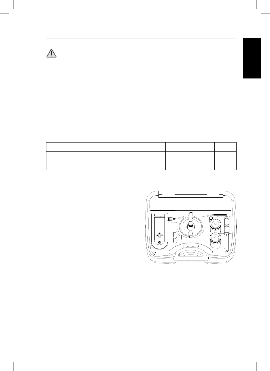
3.1. Content of
sensION ™+ DO 6
3.1.1. Component list
Code Instrument Sensor Accessories Batteries Manual
LPV4500.98.0002
LPV4551.98.0002
sensION ™+ DO 6
sensION ™+ DO 6
–– ––
LZW5120.97.0002
✓✓
✓✓✓
3.1.2. Accesorios
• Carrying case.
• Sensor electrolyte (25 mL).
• Replacement membrane
• Two 90-mL bottles for sample and sensor
cleaning.
• Tube for calibration.
sensION™
DO6
Fig. 1. Equipment composition
After removing the instrument, check each part for possible damage. All components on the attached list
must be present. If there are any missing or damaged parts, contact the manufacturer or distributor.
5
sensION+ DO 6_HACH_LANGE_0710.indd ANG:5sensION+ DO 6_HACH_LANGE_0710.indd ANG:5 14/9/10 10:53:3014/9/10 10:53:30
Page 10
3. Installation
+
+
+
3.2. Battery power
WARNING
Risk of fire or explosion. Use only AA alkaline batteries for the measuring instrument and ensure that
the batteries are correctly inserted in their compartment. Inserting batteries incorrectly can damage
the instrument and cause fires or explosions.
The measuring instrument works with three batteries (1.5 V, AA).
The batteries supplied have a useful life of approximately 500 hours.
Important note: never use different types of batteries together.
Important note: if the measuring instrument is not going to be used for a long period of time, remove
the batteries to prevent leakage in the instrument.
3.2.1. Inserting the batteries
1. Open the lid of the battery compartment by pressing and pulling on the tab.
2. Insert the batteries supplied (1.5 V AA). Note the polarity markings inside the battery compartment.
3. Close the lid of the battery compartment.
1
2
3
Tab
1
Battery compartment lid
4
Fig. 2. Inserting the batteries
6
sensION+ DO 6_HACH_LANGE_0710.indd ANG:6sensION+ DO 6_HACH_LANGE_0710.indd ANG:6 14/9/10 10:53:3114/9/10 10:53:31
2
Batteries
3
Battery compartment
4
Page 11
3. Installation
3.3. Disconnecting/connecting the sensor
The
sensION ™+ DO 6
Sensor disconnection
Sensor connection
Important: do not unscrew the connector.
kits are supplied with the sensor attached to the instrument.
Fig. 3. Disconnecting/connecting the sensor to the measuring instrument
ENGLISH
3.4. Carrying case
The carrying case can be used as a support for both, instrument and sensor, see figure:
Electrode position
when it is not in use.
7
sensION+ DO 6_HACH_LANGE_0710.indd ANG:7sensION+ DO 6_HACH_LANGE_0710.indd ANG:7 14/9/10 10:53:3114/9/10 10:53:31
Page 12
4. Start-up
4.1. General information
Important note: before start-up, make sure that the sensor is connected to the measuring instrument.
1. Connect the sensor (if necessary) to the measuring
instrument (Fig. 3, pg. 7).
2. Turn on the instrument.
3. Perform calibration (see pg. 12-14).
4. Take measurement (see pg.10).
Note: With the instrument switched off,
- Press the
measuring.
- Press the
calibration.
4.2 User interface and navigation
4.2.1 Keyboard and display
Figure 4 indicates the instrument keys and display.
key and the instrument will begin
key and the instrument will begin
Software version. Instrument
serial number.
Display
1 Measured DO values (mg/L or %).
Standby screen.
2 Temperature.
1
4
2
3
8
sensION+ DO 6_HACH_LANGE_0710.indd ANG:8sensION+ DO 6_HACH_LANGE_0710.indd ANG:8 14/9/10 10:53:3214/9/10 10:53:32
5
Fig. 4. Keypad description
3 Measuring time (hh:mm:ss).
4 Units of measurement.
5 Battery indicator.
Keypad
- Instrument on/off.
- Display light on.
- Start of measuring.
- Start of calibration.
- Selection of temperature units.
- Entry of numerical values during
set-up.
Page 13
5. Set-up
The
sensION ™+ DO 6
is supplied with the following
parameters:
– Atmospheric pressure: 1013 mb.
– Salinity: 0.0 g/L.
To display and/or modify these parameters, follow the diagram below.
ENGLISH
2 s
2 s 2 s
2 s
2 s
2 s
5.1. Atmospheric pressure
Enter the atmospheric pressure value for the instrument to make the relevant compensation.
5.2. Salinity
Enter the salinity value of the sample to be measured. This is determined with a conductivity measurement.
Important note: salinity only affects the DO concentration
measurement (mg/L).
Conversion table
specific conductivity/salinity
Conductivity (mS/cm) NaCl (g/L)
1.9 1.0
3.7 2.0
7.3 4.0
10.9 6.0
17.8 10.1
25.8 15.1
33.6 20.2
41.2 25.4
48.9 30.6
56.3 35.8
62.2 40.0
69.4 45.3
75.7 50.0
9
sensION+ DO 6_HACH_LANGE_0710.indd ANG:9sensION+ DO 6_HACH_LANGE_0710.indd ANG:9 14/9/10 10:53:3314/9/10 10:53:33
Page 14

6. Operation
6.1. Polarisation
The sensor must be connected and polarized before calibration. The measuring instrument polarizes the
sensor whenever it is connected, even if it is switched off.
Required polarisation
The sensor must be polarised 6 hours before use if:
• it is not connected to the measuring instrument
• the batteries have been inserted for the first time, they are running low or they need changing
The sensor must be polarised for 10 approximately minutes if the sensor is disconnected from the measuring
instrument for less than 5 minutes.
6.2. Measurement
1. Press to turn on the instrument.
2. Remove the sensor protector.
3. Clean the sensor with deionized water.
4. Stir the sensor uniformly in the sample, holding it by the top.
Important notes: the instrument must be calibrated before taking the first reading.
The DO sensor consumes oxygen in the measured solution; hence, the liquid in contact with the membrane
needs to be renewed for a correct measurement. Otherwise, the reading will gradually drop. Gently stir the
liquid to be measured using the sensor. The minimum flow must be 0.3 mL/s.
Before measuring, the sensor must be fully polarised.
Salt content affects oxygen measurement when the result is expressed in mg/L and it must be adjusted
manually. To do this, measure the conductivity of the sample, determine the salt content (see table on pg. 9) and
manually enter it in the instrument.
10
sensION+ DO 6_HACH_LANGE_0710.indd ANG:10sensION+ DO 6_HACH_LANGE_0710.indd ANG:10 14/9/10 10:53:3314/9/10 10:53:33
Page 15
6. Operation
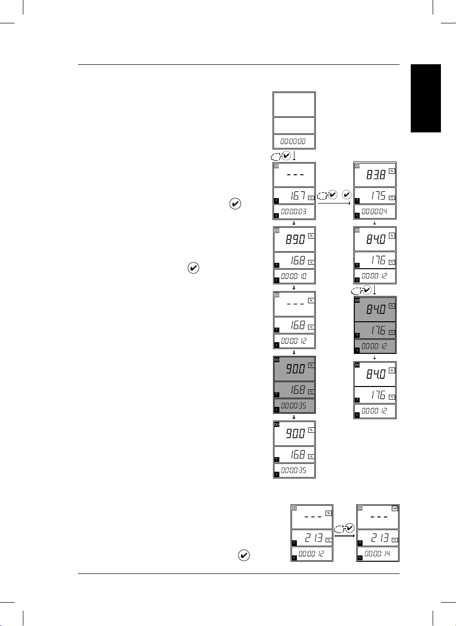
6.2.1. Stability measuring
Follow the diagram.
The reading is not locked on the screen until the sensor signal varies less than 0.1% DO (0.125 nA) for
15 sec.
Once the reading has stabilized, the screen lights up
for 2 sec.
6.2.2. Continuous measuring
Once stability measuring has begun, press the
key twice.
The instrument displays the measured value directly on
screen at all times.
The continuous reading should always be started after
beginning a stability reading (see diagram).
To end a continuous reading, press
.
The display will light up for 2 sec.
Note: if the measuring instrument is not used for 5 minutes, it will shut off automatically.
Stability
measuring
ENGLISH
Continuous
measuring
+
6.3. Changing measuring units (%/mg/L)
To change the units of measurement from % to mg/L or vice versa.
In Stability measuring, hold down
sensION+ DO 6_HACH_LANGE_0710.indd ANG:11sensION+ DO 6_HACH_LANGE_0710.indd ANG:11 14/9/10 10:53:3314/9/10 10:53:33
the
key for 2 s.
2 s
11
Page 16
6. Operation
6.4. Calibration
The sensor and the measuring instrument must be calibrated correctly to obtain precise measurements.
Important notes:
The sensor must be connected and polarized before calibration (see sensor manual).
During calibration, the membrane must not enter into contact with the surface of the water. The membrane
must remain dry since water droplets can affect calibration.
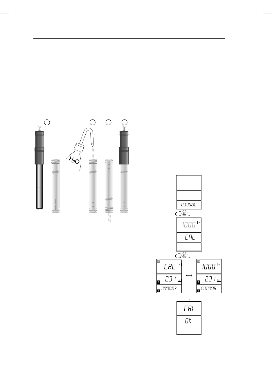
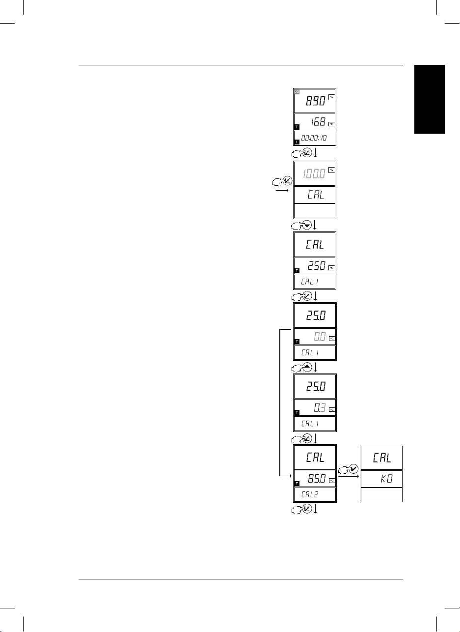
6.4.1. One-point calibration
1 2 3 4
6.4.1.1. Preparation
1. Unscrew the sensor protector.
2. Add a small amount of water to the
calibrator tube.
3. Empty the excess water by shaking
gently.
4. Screw the calibrator tube to the sensor.
Fig. 5. Preparación
6.4.1.2. Calibration
Follow the diagram.
One-point calibration is performed in air saturated water,
100% DO.
This is the most common type of calibration.
Note:
If calibration is not performed correctly, the membrane must
be cleaned and the electrolyte changed (see sensor manual).
The calibration is correct if an oxygen content of over 98% is
displayed when taking a measurement in the calibrator tube.
A value of over 99% is optimal.
If the measuring instrument is not used for 5 minutes, it shuts
off automatically.
Screw the
sensor
to the 1st tube.
12
sensION+ DO 6_HACH_LANGE_0710.indd ANG:12sensION+ DO 6_HACH_LANGE_0710.indd ANG:12 14/9/10 10:53:3414/9/10 10:53:34
Page 17
6. Operation
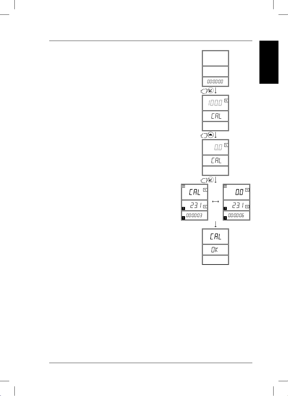
6.4.2. Two-point calibration
6.4.2.1. Preparation
1. Unscrew the sensor protector.
2. Dip the sensor into an oxygen-free solution.
3. Stir the sensor gently.
6.4.2.2. Calibration
Follow the diagram.
Note:
To perform a two-point calibration, you must be certain
that the solution is oxygen-free; otherwise, one-point
calibration (100% DO) using the calibrator tube is
preferable.
If calibration is not performed correctly, the membrane
must be cleaned and the electrolyte changed (see sensor manual). The calibration is correct if an oxygen
content of over 98% is displayed when taking a measurement in the calibrator tube. A value of over 99%
is optimal.
If the measuring instrument is not used for 5 minutes, it
shuts off automatically.
ENGLISH
Dip the sensor into an
oxygen-free
solution
13
sensION+ DO 6_HACH_LANGE_0710.indd ANG:13sensION+ DO 6_HACH_LANGE_0710.indd ANG:13 14/9/10 10:53:3414/9/10 10:53:34
Page 18
6. Operation
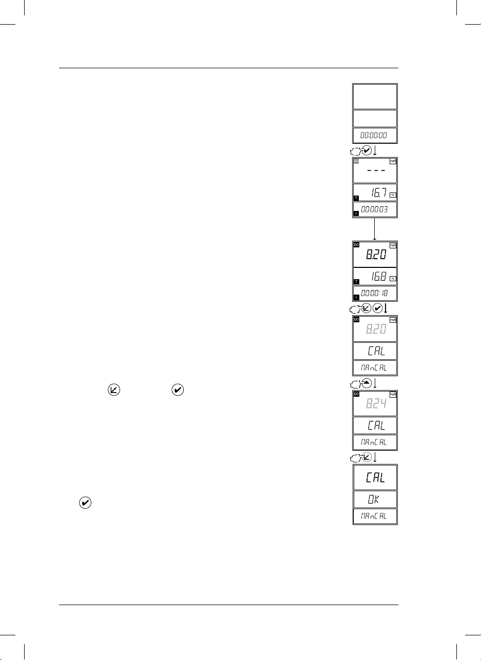
6.5. Manual calibration
Important note: before turning on the instrument, check that the DO
sensor is connected and polarised.
Manual readjustment of the dissolved oxygen measured within the
range.
When readjusting DO, the instrument behaves as though it were performing a one-point calibration.
6.5.1. Preparation
1. Unscrew the sensor protector.
2. Rinse the sensor with deionized water.
3. Dip the sensor into the solution in which manual calibration is to be
performed.
Note: Before beginning manual calibration, you must take a measurement in the standard to be used in the calibration.
6.5.2. Calibration
Stir gently holding the sensor by the handle.
Follow the diagram.
(1)
(1)
Hold down
and then press .
Note: If the measuring instrument is not used for 5 minutes, it shuts off
automatically.
If errors occur during calibration, an error message will appear on screen
(see pg. 19).
Before beginning manual calibration, you must take a measurement in the
standard to be used in the calibration.
Important note: to exit calibration without saving the adjustment,
press
14
sensION+ DO 6_HACH_LANGE_0710.indd ANG:14sensION+ DO 6_HACH_LANGE_0710.indd ANG:14 14/9/10 10:53:3414/9/10 10:53:34
.
Page 19
6. Operation
6.6. Readjusting temperature
The instrument can correct the deviation of a temperature
probe (built into DO sensors) at 25°C and 85°C (77°F
and 185°F).
This allows the instrument to be used as a precision thermometer.
Follow the diagram.
2 s
ENGLISH
Enter the correction of the
temperature sensor at
25 °C (77 °F).
Enter the correction of the
temperature sensor at
85 °C (185 °F).
To exit adjustment without saving the data.
15
sensION+ DO 6_HACH_LANGE_0710.indd ANG:15sensION+ DO 6_HACH_LANGE_0710.indd ANG:15 14/9/10 10:53:3514/9/10 10:53:35
Page 20
6. Operation
6.7. Restoring factory settings
The current calibration can be erased and restored to the factory
settings.
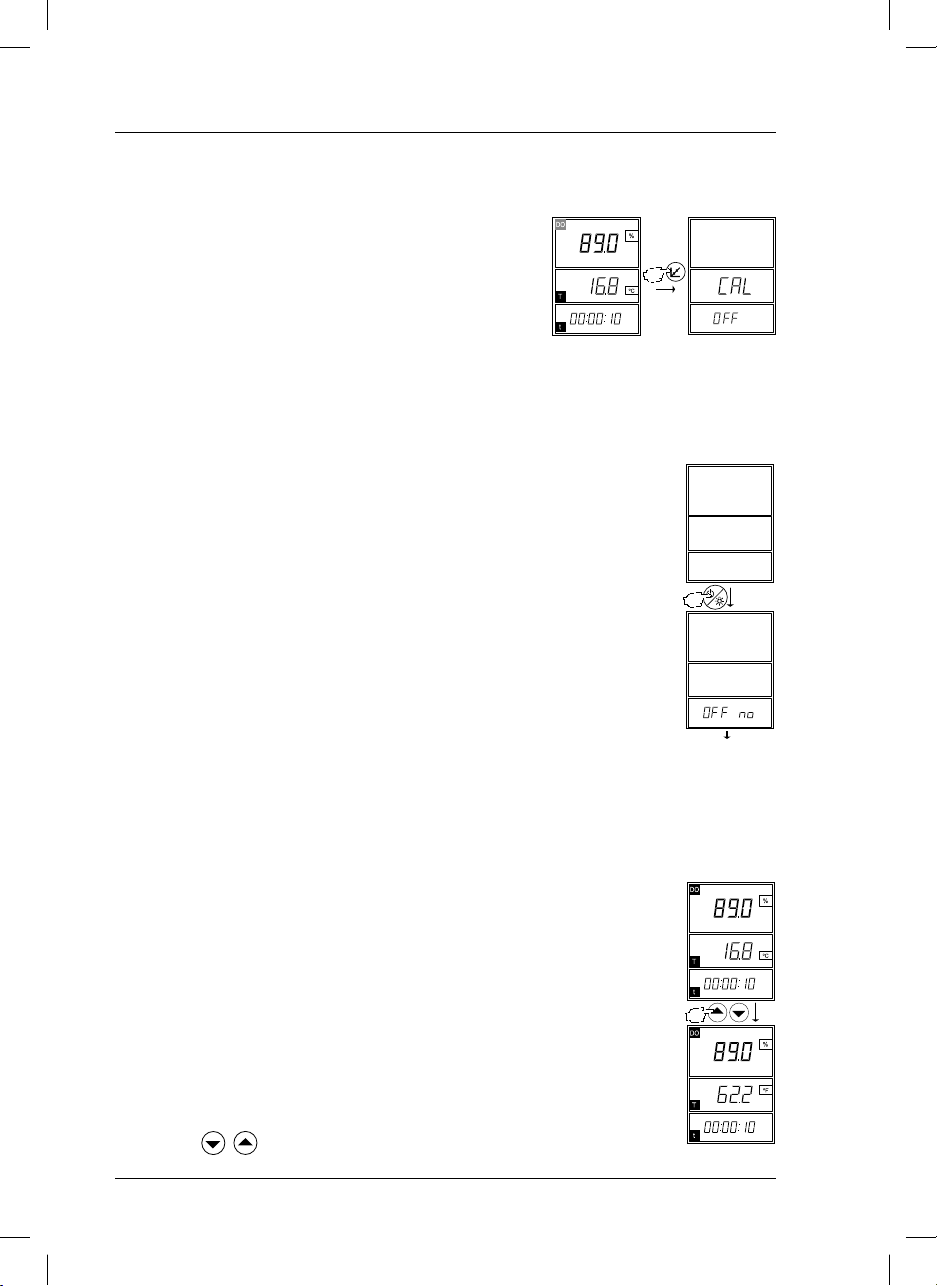
6.8. Disabling auto power off
If the measuring instrument is not used for 5 minutes, it turns itself off
automatically. This automatic power off feature can be disabled.
2 s
2 s
Automatic power
off is disabled
etc.
6.9. Changing temperature units
The instrument is shipped ready to measure temperature and express the values in °C.
Follow the diagram to change the units to °F.
Stable measurement
(1)
(1) Press the
16
sensION+ DO 6_HACH_LANGE_0710.indd ANG:16sensION+ DO 6_HACH_LANGE_0710.indd ANG:16 14/9/10 10:53:3514/9/10 10:53:35
keys simultaneously.
Page 21
6. Operation
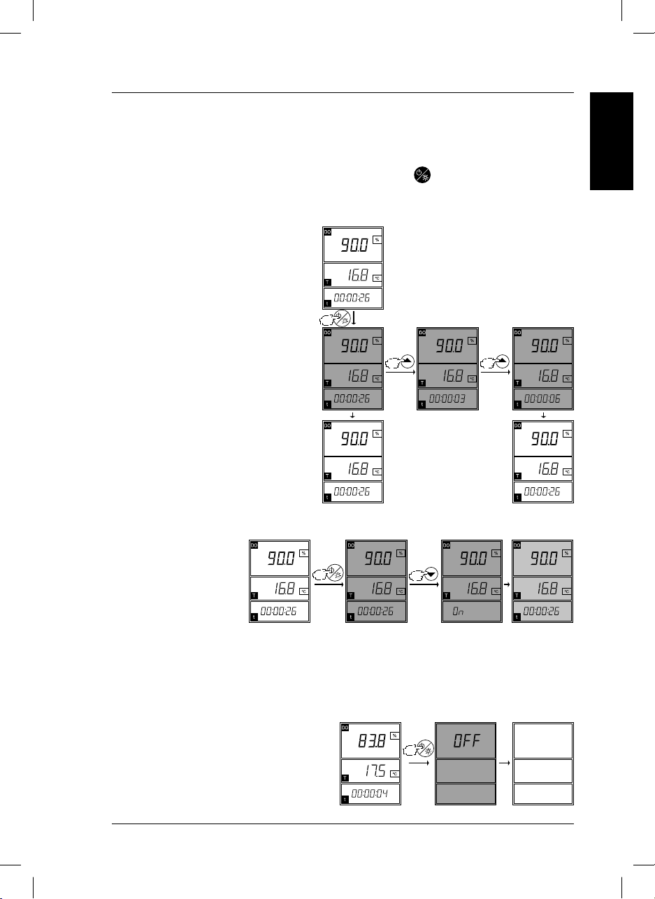
6.10. Display backlighting
At the end of a measurement, whether in stability or continuous, the screen automatically lights up for 2
seconds.
The user can also light up the screen at any other time by pressing
, which will backlight the screen
for 3 seconds.
Changing backlighting time
Follow the diagram.
Notes: only the time of the manual
backlighting of the display can be
modified.
You cannot change the automatic
backlighting time (2 sec.) after
completing a measurement.
By increasing the display’s
backlighting time, you reduce the
autonomy of the instrument (battery
life).
Immediately
inmediatamente
3 s 6 s
ENGLISH
Continuous backlighting
In low-light environments, it
is advisable to work with the
screen lit.
Note: backlighting the display
reduces the autonomy of the
instrument (battery life).
6.11. Shutting down the instrument
Follow the diagram below.
2 s
17
sensION+ DO 6_HACH_LANGE_0710.indd ANG:17sensION+ DO 6_HACH_LANGE_0710.indd ANG:17 14/9/10 10:53:3514/9/10 10:53:35
Page 22
7. Maintenance
ATTENTION!
Potentially dangerous to skin and eyes with chemical/biological exposure.
The tasks described in this section of the manual should only be performed by qualified personnel.
7.1. Cleaning the measuring instrument and accessories
Important note: never use cleaning products such as turpentine, acetone or similar products to clean the
instrument, including the screen and accessories.
Only clean the carrying case and accessories with a soft damp cloth.
A mild soap solution can also be used. Dry the clean parts carefully with a soft cotton cloth.
7.2. Storing the instrument
When preparing to store the instrument for long periods of time, remove the batteries to prevent leakage
and subsequent damage to the measuring instrument.
7.3. Changing batteries
WARNING
Risk of fire or explosion. Use only AA alkaline batteries for the measuring instrument and ensure that
the batteries are correctly inserted in their compartment. Inserting batteries incorrectly can damage
the measuring instrument and cause fires or explosions.
The batteries supplied have a useful life of approximately 500 hours.
1. Press
2. Disconnect the sensor.
3. Open the lid of the battery compartment (Fig. 2, pg. 6).
4. Remove the old batteries.
5. Insert the new batteries (1.5V AA). Note the polarity markings inside the battery compartment.
Important note: never use different types of batteries together.
6. Close the lid of the battery compartment.
18
sensION+ DO 6_HACH_LANGE_0710.indd ANG:18sensION+ DO 6_HACH_LANGE_0710.indd ANG:18 14/9/10 10:53:3514/9/10 10:53:35
to turn off the instrument.
Page 23
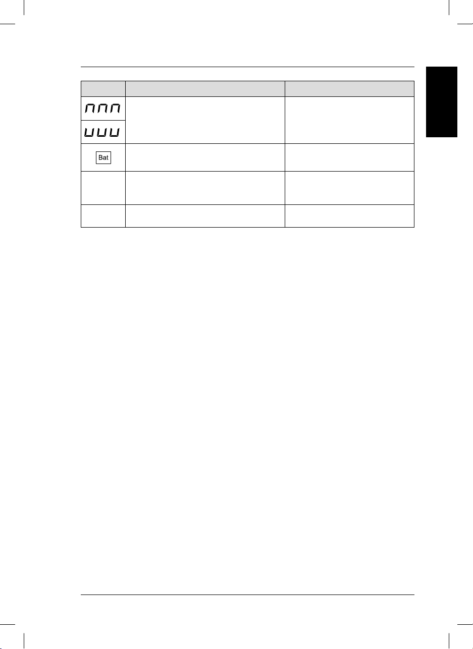
8. Error messages
Display Caused by Action
- Measurement of D.O. or temperature out of range.
- In calibration:
- Standard 0%: limits <0 nA and >2nA
- Standard 100%: limits <30 nA and >110 nA
Low battery charge. Replace the batteries.
Check standards.
Check sensor.
ENGLISH
Unstable reading during a stability measurement or
during calibration.
E1
180-second timeout.
Exceeded upper limit of sensor current during
E2
measurement ≥250 nA
Check sensor.
Check polarisation.
Check flow.
Check sensor.
19
sensION+ DO 6_HACH_LANGE_0710.indd ANG:19sensION+ DO 6_HACH_LANGE_0710.indd ANG:19 14/9/10 10:53:3614/9/10 10:53:36
Page 24

9. Accessories and spare parts
Code Description
LZW9991.99 Carrying case.
LZW5120.97.0002 DO sensor (polarographic), with 3 m cable, MP-5 connector. Accessories: 1 membrane.
LZW9811.99 Electrolyte for DO sensor 51 20, 25 mL.
LZW5123.99 Tube for DO sensor calibration, 51 20.
LZW9314.99 90-mL bottle for sample and sensor cleaning.
LZW5125.99 Replacement DO membrane for DO sensor 51 20.
20
sensION+ DO 6_HACH_LANGE_0710.indd ANG:20sensION+ DO 6_HACH_LANGE_0710.indd ANG:20 14/9/10 10:53:3614/9/10 10:53:36
Page 25

10. Warranty, liability and complaints
The manufacturer warrants that the product supplied is free of material and manufacturing defects and undertakes
the obligation to repair or replace any defective parts at zero cost. The warranty period for instruments is 24
months.
With the exclusion of the further claims, the supplier is liable for defects including the lack of assured properties
as follows: all those parts that can be demonstrated to have become unusable or that can only be used with
significant limitations due to a situation present prior to the transfer of risk, in particular due to incorrect design,
poor materials or inadequate finish will be improved or replaced, at the supplier’s discretion. The identification
of such defects must be notified to the supplier in writing without delay, however at the latest 7 days after the
identification of the fault. If the customer fails to notify the supplier, the product is considered approved despite
the defect. Further liability for any direct or indirect damages is not accepted.
If instrument-specific maintenance and servicing work defined by the supplier is to be performed within the
warranty period by the customer (maintenance) or by the supplier (servicing) and these requirements are not met,
claims for damages due to the failure to comply with the requirements are rendered void.
Any further claims, in particular claims for consequential damages cannot be made.
Consumables and damage caused by improper handling, poor installation or incorrect use are excluded from
this clause.
ENGLISH
21
sensION+ DO 6_HACH_LANGE_0710.indd ANG:21sensION+ DO 6_HACH_LANGE_0710.indd ANG:21 14/9/10 10:53:3614/9/10 10:53:36
Page 26

sensION+ DO 6_HACH_LANGE_0710.indd ANG:22sensION+ DO 6_HACH_LANGE_0710.indd ANG:22 14/9/10 10:53:3614/9/10 10:53:36
Page 27

Inhaltsverzeichnis
1. Technische Daten . . . . . . . . . . . . . . . . . . . . . . . . . . . . 3
2. Allgemeine Informationen . . . . . . . . . . . . . . . . . . . . 4
2.1. Sicherheitshinweise . . . . . . . . . . . . . . . . . . . . . . . . 4
2.1.1. Bedeutung von Gefahrenhinweisen . . . . . . . . 4
2.1.2. Warnetiketten . . . . . . . . . . . . . . . . . . . . . . 4
2.2. Allgemeine Informationen . . . . . . . . . . . . . . . . . . . . 4
3. Installation . . . . . . . . . . . . . . . . . . . . . . . . . . . . . . . . 5
3.1. Inhalt . . . . . . . . . . . . . . . . . . . . . . . . . . . . . . . . 5
3.1.1. Lieferumfang . . . . . . . . . . . . . . . . . . . . . . . 5
3.1.2. Zubehör . . . . . . . . . . . . . . . . . . . . . . . . . . 5
3.2. Batteriebetrieb . . . . . . . . . . . . . . . . . . . . . . . . . . . . 6
3.2.1. Einlegen der Batterien . . . . . . . . . . . . . . . . . 6
3.3. Trennen/Anschließen des Sensors . . . . . . . . . . . . . . 7
3.4. Transportkoffer . . . . . . . . . . . . . . . . . . . . . . . . . . . . . 7
4. Inbetriebnahme . . . . . . . . . . . . . . . . . . . . . . . . . . . . . 8
4.1. Allgemeine Informationen . . . . . . . . . . . . . . . . . . . . 8
4.2. Benutzeroberfläche und Bedienung . . . . . . . . . . . . . 8
4.2.1. Tastatur und Display . . . . . . . . . . . . . . . . . . 8
5. Einstellungen . . . . . . . . . . . . . . . . . . . . . . . . . . . . . . . 9
5.1. Luftdruck . . . . . . . . . . . . . . . . . . . . . . . . . . . . . . . . 9
5.2. Salinität . . . . . . . . . . . . . . . . . . . . . . . . . . . . . . . . 9
6. Bedienung und Funktion . . . . . . . . . . . . . . . . . . . . . . 9
6.1. Polarisation . . . . . . . . . . . . . . . . . . . . . . . . . . . . . . 10
6.2. Messung . . . . . . . . . . . . . . . . . . . . . . . . . . . . . . . . 10
6.2.1. Messung mit Stabilisierung. . . . . . . . . . . . . . 11
6.2.2. Kontinuierliche Messung . . . . . . . . . . . . . . . 11
6.3. Änderung der Messeinheiten (%/mg/l) . . . . . . . . . . . 11
6.4. Kalibrierung . . . . . . . . . . . . . . . . . . . . . . . . . . . . . 12
6.4.1. Ein-Punkt-Kalibrierung . . . . . . . . . . . . . . . . . 12
6.4.1.1. Vorbereitung . . . . . . . . . . . . . . . . 12
6.4.1.2. Kalibrierung . . . . . . . . . . . . . . . . 12
6.4.2. Zwei-Punkt-Kalibrierung . . . . . . . . . . . . . . . . 13
6.4.2.1. Vorbereitung . . . . . . . . . . . . . . . . 13
6.4.2.2. Kalibrierung . . . . . . . . . . . . . . . . 13
6.5. Manuelle Kalibrierung . . . . . . . . . . . . . . . . . . . . . . 14
6.5.1. Vorbereitung . . . . . . . . . . . . . . . . . . . . . . . 14
6.5.2. Kalibrierung . . . . . . . . . . . . . . . . . . . . . . . . 14
6.6. Nachregelung der Temperatur . . . . . . . . . . . . . . . . . 15
6.7. Wiederherstellung der Werkseinstellungen . . . . . . . . 16
6.8. Deaktivierung der automatischen Abschaltung . . . . . . 16
6.9. Umschalten der Temperaturmesseinheiten . . . . . . . . . 16
6.10. Display-Beleuchtung . . . . . . . . . . . . . . . . . . . . . . . . 17
6.11. Ausschalten des Geräts . . . . . . . . . . . . . . . . . . . . . . 17
7. Wartung . . . . . . . . . . . . . . . . . . . . . . . . . . . . . . . . 18
7.1. Reinigung des Messgeräts und Zubehörs . . . . . . . . . 18
7.2. Lagerung des Geräts . . . . . . . . . . . . . . . . . . . . . . . 18
7.3. Batteriewechsel . . . . . . . . . . . . . . . . . . . . . . . . . . . 18
8. Fehlermeldungen . . . . . . . . . . . . . . . . . . . . . . . . . . . . 19
9. Zubehör und Ersatzteile . . . . . . . . . . . . . . . . . . . . . . 20
10. Gewährleistung, Haftung und Reklamationen. . . . 21
Contact Information
DEUTSCH
1
sensION+ DO 6_HACH_LANGE_0710.indd ALE:1sensION+ DO 6_HACH_LANGE_0710.indd ALE:1 14/9/10 10:53:3614/9/10 10:53:36
Page 28

sensION+ DO 6_HACH_LANGE_0710.indd ALE:2sensION+ DO 6_HACH_LANGE_0710.indd ALE:2 14/9/10 10:53:3614/9/10 10:53:36
Page 29

1. Technische Daten
Technische Daten können jederzeit ohne Vorankündigung geändert werden.
Technische Daten
Display
Tastatur
Messbereiche
Wiederholbarkeit (± 1 Dezimalstelle)
Messfehler (± 1 Dezimalstelle)
Temperatur
Temperaturkompensation
Korrektur der Salinität
und des Luftdrucks
Standardkalibrierungen
Abmessungen des Messgerätes und Umgebungsbedingungen
Betriebstemperatur
Lagerungstemperatur
Umgebungsbedingungen
Gewicht
Größe
Sonstige technische Daten
Energieverwaltung
Schutzklasse
Stromversorgung (Batterie) 3 Batterien Typ AA 1,5V
Stecker
Garantie
Garantie
LCD-Grafikdisplay mit Hintergrundbeleuchtung und Piktogrammen
Fünf Tasten mit PET-Abdeckung
Sättigung 0,0 bis 199,9 % und 200 bis 250 % (25 °C)
Konzentration
Gelöster Sauerstoff ≤ 0,2 des Messwerts
Temperatur ≤ 0,1 °C (≤ 0.1 °F)
Gelöster Sauerstoff ≤ 0,5 des Messwerts
Temperatur ≤ 0,2 °C (≤ 0.4 °F)
0,0 bis 50,0 °C (0 bis 122°F)
Automatisch, mit NTC-Sensor
Automatisch bei manueller Dateneingabe
In ein oder zwei Punkten. Sättigung 0 % und 100 %
von 0 °C bis 50 °C (32 °F bis 122 °F)
von -15 °C bis 65 °C (5 °F bis 149 °F)
80 % relative Luftfeuchtigkeit (nicht kondensierend)
300 g
186 x 73 x 38 mm
Automatische Abschaltung nach fünf Minuten Inaktivität.
IP 67
Betriebsdauer mehr als 500 Stunden
MP-5, mehrpolig mit fünf Kontakten
Zwei Jahre
0,00 bis 19,99 mg/l und 20,0 bis 22,0 g/l
(25 °C)
DEUTSCH
3
sensION+ DO 6_HACH_LANGE_0710.indd ALE:3sensION+ DO 6_HACH_LANGE_0710.indd ALE:3 14/9/10 10:53:3614/9/10 10:53:36
Page 30

2. Allgemeine Informationen
Da wir unsere Geräte laufend verbessern, können Unterschiede zwischen den Informationen in dieser
Bedienungsanleitung und dem von Ihnen erworbenen Gerät nicht ausgeschlossen werden.
2.1. Sicherheitshinweise
Lesen Sie die vorliegende Bedienungsanleitung vor der Montage und Installation des Geräts vollständig durch.
Beachten Sie alle Warnetiketten.
2.1.1. Bedeutung von Gefahrenhinweisen
GEFAHR
Weist auf eine potenzielle oder unmittelbare Gefahrensituation hin, deren Nichtbeachtung zu
ernsthaften Verletzungen oder sogar zum Tod führt.
WARNUNG
Weist auf eine potenzielle oder unmittelbare Gefahrensituation hin, deren Nichtbeachtung zu
ernsthaften Verletzungen oder sogar zum Tod führen kann.
VORSICHT
Weist auf eine mögliche Gefahrensituation hin, die zu leichten bis mittelschweren Verletzungen
führen kann.
Wichtiger Hinweis: Weist auf eine Situation hin, die zu Schäden am Gerät führen kann. Wichtige
Information, die beim Umgang mit dem Gerät besonders zu beachten ist.
Hinweis: Zusätzliche Information über den Umgang mit dem Gerät.
2.1.2. Warnetiketten
Beachten Sie alle am Gerät angebrachten Etiketten, Schilder und Aufkleber.
Dieses Symbol verweist auf Bedienungs- und/oder Sicherheitshinweise in der Bedienungsanleitung.
Elektrogeräte, die mit diesem Symbol gekennzeichnet sind, dürfen nach dem 12. August 2005 in Europa nicht im normalen öffentlichen Abfallsystem entsorgt werden, sondern müssen gesondert gesammelt
werden. Nach den Maßgaben der EU-Richtlinie 2002/96/EG müssen Elektro- und Elektronik-Altgeräte
von den Nutzern kostenlos zur Entsorgung an den Hersteller zurückgegeben werden können.
Hinweis: Zur Rücknahme zwecks Recycling wenden Sie sich bitte an den Hersteller oder Lieferanten des
Geräts. Bitten Sie ihn um Informationen zur Rückgabe von Elektro- und Elektronik-Altgeräten, von durch
den Hersteller geliefertem Elektrozubehör und von allen Zusatzkomponenten für die ordnungsgemäße
Entsorgung.
2.2. Allgemeine Informationen
Der
sensION ™+ DO 6
wird die Sättigung (in %) oder die Konzentration (in mg/l) sowie die Temperatur der Probe. Der Luftdruck
und der Salzgehalt werden automatisch korrigiert.
Um einen Messwert bestimmen zu können, muss vorher ein Sensor angeschlossen werden (Abb. 3, S. 7).
4
sensION+ DO 6_HACH_LANGE_0710.indd ALE:4sensION+ DO 6_HACH_LANGE_0710.indd ALE:4 14/9/10 10:53:3614/9/10 10:53:36
ist ein Gerät zur polarografischen Messung von gelöstem Sauerstoff. Gemessen
Page 31

3. Installation
WARNUNG
Sturzgefahr. Messungen werden mit diesem Gerät direkt vor Ort vorgenommen. Zur Vermeidung
von Stürzen müssen alle geltenden Sicherheitsvorschriften bzgl. der Verwendung von Trageriemen
und der Verwendung der entsprechenden Sicherheitskleidung eingehalten werden.
Verletzungsgefahr. Halten Sie das Messgerät stets im ausreichenden Abstand vom Körper.
Der Mess-Sensor könnte sich aus Versehen an einem Objektträger oder Rührer verfangen und den
Benutzer so durch das Sensorkabel gefährden.
3.1. Lieferumfang des
sensION ™+ DO 6
3.1.1. Lieferumfang
Code Gerät Sensor Zubehör Batterien
LPV4500.98.0002
LPV4551.98.0002
sensION ™+ DO 6
sensION ™+ DO 6
–– ––
LZW5120.97.0002
✓✓✓
3.1.2. Zubehör
• Hartschalenkoffer.
• Elektrolyt für den Sensor (25 ml).
• Ersatzmembran.
• Zwei 90-ml-Flaschen zum Einmessen und Spülen
des Sensors.
• Kalibrierhülsen
sensION™
DO6
Abb. 1. Lieferumfang
Bedienungs-
anleitung
✓✓
DEUTSCH
Überprüfen Sie unmittelbar nach dem Auspacken des Messgeräts alle Einzelteile auf Beschädigungen. Alle
aufgeführten Bestandteile müssen vorhanden sein. Falls eines der Teile fehlt oder beschädigt ist, wenden
Sie sich an den Hersteller oder den Händler.
5
sensION+ DO 6_HACH_LANGE_0710.indd ALE:5sensION+ DO 6_HACH_LANGE_0710.indd ALE:5 14/9/10 10:53:3614/9/10 10:53:36
Page 32

3. Installation
+
+
+
3.2. Batteriebetrieb
WARNUNG
Brand- und Explosionsgefahr. Verwenden Sie für das Messgerät ausschließlich Alkali-Batterien
vom Typ AA und vergewissern Sie sich, dass die Batterien ordnungsgemäß in das vorgesehene
Batteriefach eingelegt wurden. Falsch eingesetzte Batterien können zu Schäden am Gerät, Bränden
oder zu Explosionen führen.
Für den Betrieb benötigt das Messgerät drei Batterien (Typ AA mit 1,5 V).
Die mitgelieferten Batterien verfügen über eine Lebensdauer von ca. 500 Stunden.
Wichtiger Hinweis: Verwenden Sie niemals unterschiedliche Batterietypen gleichzeitig.
Wichtiger Hinweis: Wird das Messgerät über einen längeren Zeitraum hinweg nicht verwendet,
nehmen Sie die Batterien heraus, damit diese nicht eventuell im Gerät auslaufen.
3.2.1. Einlegen der Batterien
1. Drücken Sie zum Öffnen des Batteriefachdeckels die Lasche nach unten und ziehen Sie dann daran.
2. Legen Sie die im Lieferumfang enthaltenen Batterien (Typ AA mit 1,5 V) ein. Beachten Sie dabei die
Polaritätsmarkierungen im Batteriefach.
3. Schließen Sie den Batteriefachdeckel.
1
2
3
Lasche
1
Batteriefachdeckel
2
Batterien
4
Abb. 2. Einlegen der Batterien
6
sensION+ DO 6_HACH_LANGE_0710.indd ALE:6sensION+ DO 6_HACH_LANGE_0710.indd ALE:6 14/9/10 10:53:3714/9/10 10:53:37
3
Batteriefach
4
Page 33

3. Installation
3.3. Trennen/Anschließen des Sensors.
Der Sensor ist bereits ab Werk an das Gerät angeschlossen.
Trennen des Sensors
Anschließen des Sensors
Abb. 3. Trennen/Anschließen des Sensors an das Messgerät
Wichtiger Hinweis: Schrauben Sie den Stecker nicht ab.
DEUTSCH
3.4. Transportkoffer
Der Transportkoffer kann als Elektroden- und Messgeräthalter verwendet werden.
Position der Elektrode
wenn diese nicht
verwendet wird.
7
sensION+ DO 6_HACH_LANGE_0710.indd ALE:7sensION+ DO 6_HACH_LANGE_0710.indd ALE:7 14/9/10 10:53:3714/9/10 10:53:37
Page 34

4. Inbetriebnahme
4.1. Allgemeine Informationen
Wichtiger Hinweis: Stellen Sie vor der Inbetriebnahme sicher, dass der Sensor an das Messgerät an-
geschlossen ist.
1. Schließen Sie (falls erforderlich) den Sensor an
das Messgerät an (Abb. 3, S. 7).
2. Schalten Sie das Gerät ein.
3. Führen Sie die Kalibrierung durch (siehe Seiten 12-14).
4. Führen Sie die Messung durch (siehe Seite 10).
Hinweis: Wenn das Gerät ausgeschaltet ist:
- Drücken Sie die Taste
, um direkt zur Messung zu wechseln.
Software-Version. Seriennummer
des Geräts.
- Drücken Sie die Taste , um direkt zur Kalibrierung zu wechseln.
4.2 Benutzeroberfläche und Bedienung
4.2.1 Tastatur und Display
Abbildung 4 zeigt die Tasten und das Display des Geräts.
Display
1 Messwerte GS (mg/l oder %)
2 Temperatur
1
4
2
3
5
3 Dauer der Messung (hh:mm:ss)
4 Messeinheiten
5 Batterieanzeige
Tastatur
- Gerät ein-/ausschalten
- Display-Beleuchtung einschalten
- Start der Messung
- Start der Kalibrierung
- Auswahl der Temperatureinheiten
- Eingabe numerischer Werte während der Konfiguration
Startbildschirm.
Abb. 4. Tastaturbelegung
8
sensION+ DO 6_HACH_LANGE_0710.indd ALE:8sensION+ DO 6_HACH_LANGE_0710.indd ALE:8 14/9/10 10:53:3914/9/10 10:53:39
Page 35

5. Einstellungen
Das
sensION ™+ DO 6
den folgenden Werkseinstellungen
ausgeliefert:
– Luftdruck: 1013 mbar
– Salinität: 0,0 g/l.
Um diese Werte anzuzeigen
bzw. zu ändern, folgen Sie
nebenstehendem Schema.
wird mit
2 s 2 s
2 s
2 s
2 s
DEUTSCH
2 s
5.1. Luftdruck
Geben Sie den Luftdruckwert ein, damit das Gerät die entsprechende Kompensation vornimmt.
5.2. Salinität
Geben Sie den Salzgehalt der zu messenden Probe ein. Dieser
wird durch eine Leitfähigkeitsmessung ermittelt.
Wichtiger Hinweis: Die Salinität wirkt sich nur auf die
Messung der Konzentration des gelösten Sauerstoffs aus. (mg/l).
sensION+ DO 6_HACH_LANGE_0710.indd ALE:9sensION+ DO 6_HACH_LANGE_0710.indd ALE:9 14/9/10 10:53:3914/9/10 10:53:39
Umrechnungstabelle
spezifische Leitfähigkeit/Salinität
Leitfähigkeit (mS/cm) NaCl (g/l)
1,9 1,0
3,7 2,0
7,3 4,0
10,9 6,0
17,8 10,1
25,8 15,1
33,6 20,2
41,2 25,4
48,9 30,6
56,3 35,8
62,2 40,0
69,4 45,3
75,7 50,0
9
Page 36

6. Bedienung und Funktion
6.1. Polarisation
Vor der Kalibrierung muss der Sensor angeschlossen und polarisiert werden. Ist der Sensor an das Messgerät angeschlossen, wird er auch vom ausgeschalteten Messgerät polarisiert.
Erforderliche Polarisation
Der Sensor muss sechs Stunden vor der Verwendung polarisiert werden, wenn:
• er nicht an das Messgerät angeschlossen ist
• zum ersten Mal Batterien eingesetzt wurden, die Batterien so gut wie leer sind oder ausgetauscht werden
müssen.
Der Sensor muss ca. zehn Minuten polarisiert werden, wenn er weniger als fünf Minuten nicht an das
Messgerät angeschlossen war.
6.2. Messung
1. Drücken Sie , um das Gerät einzuschalten.
2. Entfernen Sie die Schutzkappe vom Sensor.
3. Spülen Sie den Sensor mit destilliertem Wasser.
4. Halten Sie den Sensor am Kopfteil fest, und rühren Sie die Probe gleichmäßig.
Wichtige Hinweise: Vor der ersten Messung muss das Gerät kalibriert werden.
Der Sauerstoffsensor verbraucht Sauerstoff der Messlösung; aus diesem Grund ist es für eine korrekte
Messung erforderlich, die Flüssigkeit, die mit der Membran in Kontakt gekommen ist, auszutauschen. Wird
die Flüssigkeit nicht ausgetauscht, sinkt der Messwert langsam ab. Es wird empfohlen, die Flüssigkeit
vorsichtig mit dem Sensor selbst zu rühren. Die Mindestanströmung beträgt 0,3 ml/s.
Vor der Messung muss der Sensor vollständig polarisiert werden.
Der Salzgehalt wirkt sich auf die Sauerstoffmessung aus, wenn das Ergebnis in mg/l angezeigt wird, und
muss manuell angepasst werden. Hierfür messen Sie die Leitfähigkeit der Probe, bestimmen den Salzgehalt
(siehe Tabelle S. 9) und geben diesen in das Gerät ein.
10
sensION+ DO 6_HACH_LANGE_0710.indd ALE:10sensION+ DO 6_HACH_LANGE_0710.indd ALE:10 14/9/10 10:53:3914/9/10 10:53:39
Page 37

6. Bedienung und Funktion
6.2.1. Messung mit Stabilisierung
Folgen Sie nebenstehendem Schema.
Der Messwert erscheint erst fest im Display, wenn sich
das Sensorsignal innerhalb von 15 Sekunden um weniger als 0,1 % gelösten Sauerstoff (0,125 nA) verändert.
Nach der Stabilisierung des Messwerts wird das Display zwei Sekunden lang beleuchtet.
6.2.2. Kontinuierliche Messung
Nachdem Sie die Messung mit Stabilisierung eingeleitet haben, drücken Sie zweimal auf die Taste
Das Messgerät zeigt direkt auf dem Display den zum jeweiligen Zeitpunkt gemessenen Wert an.
Der kontinuierlichen Messung geht stets das Einleiten einer Messung
mit Stabilisierung (siehe Schema) voraus.
Um die kontinuierliche Messung zu beenden, drücken Sie die Taste
.
Das Display wird zwei Sekunden lang beleuchtet.
Hinweis: Wird das Messgerät fünf Minuten lang
nicht benutzt, schaltet es sich automatisch aus.
.
Messung mit
Stabilisierung
Kontinuierliche
Messung
+
DEUTSCH
6.3. Änderung der Messeinheiten
(%/mg/l)
So ändern Sie die Messeinheiten von % auf mg/l oder
umgekehrt.
Messung mit Stabilisierung: Halten Sie
die Taste
sensION+ DO 6_HACH_LANGE_0710.indd ALE:11sensION+ DO 6_HACH_LANGE_0710.indd ALE:11 14/9/10 10:53:3914/9/10 10:53:39
zwei Sekunden lang gedrückt.
2 s
11
Page 38

6. Bedienung und Funktion
6.4. Kalibrierung
Um genau Messwerte zu erhalten, müssen Sensor und Messgerät korrekt kalibriert werden.
Wichtige Hinweise:
Vor der Kalibrierung muss der Sensor angeschlossen und polarisiert werden (siehe Bedienungsanleitung
des Sensors).
Während der Kalibrierung darf die Membran nicht in Berührung mit der Wasseroberfläche gelangen. Die
Membran muss trocken sein, da Wassertropfen die Kalibrierung beeinträchtigen können.
6.4.1. Ein-Punkt-Kalibrierung
6.4.1.1. Vorbereitung
1 2 3 4
Abb. 5. Vorbereitung
6.4.1.2. Kalibrierung
Folgen Sie nebenstehendem Schema.
Die Ein-Punkt-Kalibrierung wird in durch Wasserdampf gesättigter Luft vorgenommen, 100 % gelöster Sauerstoff.
Dies ist die am häufigsten verwendete Kalibriermethode.
1. Schrauben Sie die Schutzkappe vom
Sensor ab.
2. Geben Sie etwas Wasser in das Kalibrierröhrchen.
3. Schütteln Sie das überschüssige
Wasser leicht ab.
4. Schrauben Sie das Kalibrierröhrchen
auf den Sensor.
Den Sensor in
das
Röhrchen
erste
schrauben.
Hinweise:
Bei nicht korrekt durchgeführter Kalibrierung muss die Membran gereinigt und der Elektrolyt ausgetauscht werden (siehe
Bedienungsanleitung des Sensors). Die Kalibrierung wurde
korrekt durchgeführt, wenn bei einer Messung im Kalibrierröhrchen ein Sauerstoffgehalt von mehr als 98 % angezeigt
wird. Ein Wert über 99 % ist der bestmögliche Wert.
Wird das Messgerät fünf Minuten lang nicht benutzt, schaltet es sich automatisch aus.
12
sensION+ DO 6_HACH_LANGE_0710.indd ALE:12sensION+ DO 6_HACH_LANGE_0710.indd ALE:12 14/9/10 10:53:4014/9/10 10:53:40
Page 39

6. Bedienung und Funktion
6.4.2. Zwei-Punkt-Kalibrierung
6.4.2.1. Vorbereitung
1. Schrauben Sie die Schutzkappe vom Sensor ab.
2. Führen Sie den Sensor in eine sauerstofffreie Lö-
sung ein.
3. Schütteln Sie den Sensor vorsichtig.
6.4.2.2. Kalibrierung
Folgen Sie nebenstehendem Schema.
Hinweise:
Für eine Zwei-Punkt-Kalibrierung ist es unbedingt erforderlich, dass die zu verwendende Lösung frei von
Sauerstoff ist. Andernfalls ist eine Ein-Punkt-Kalibrierung
(100 % gelöster Sauerstoff) mittels Kalibrierröhrchen
vorzuziehen.
Bei nicht korrekt durchgeführter Kalibrierung muss die
Membran gereinigt und der Elektrolyt ausgetauscht
werden (siehe Bedienungsanleitung des Sensors). Die
Kalibrierung wurde korrekt durchgeführt, wenn bei
einer Messung im Kalibrierröhrchen ein Sauerstoffgehalt von mehr als 98 % angezeigt wird. Ein Wert über
99 % ist der bestmögliche Wert.
Wird das Messgerät fünf Minuten lang nicht benutzt,
schaltet es sich automatisch aus.
Führen Sie
den Sensor
in eine sauerstofffreie
Lösung ein.
DEUTSCH
13
sensION+ DO 6_HACH_LANGE_0710.indd ALE:13sensION+ DO 6_HACH_LANGE_0710.indd ALE:13 14/9/10 10:53:4014/9/10 10:53:40
Page 40

6. Bedienung und Funktion
6.5. Manuelle Kalibrierung
Wichtiger Hinweis: Überprüfen Sie vor dem Einschalten des Geräts,
dass der Sauerstoffsensor angeschlossen und polarisiert ist.
Passen Sie den Messwert des gelösten Sauerstoffs manuell auf einen beliebigen Wert des Messbereichs an.
Eine Neueinstellung des gelösten Sauerstoffs hat auf das Gerät denselben Effekt wie eine Ein-Punkt-Kalibrierung.
6.5.1. Vorbereitung
1. Schrauben Sie die Schutzkappe vom Sensor ab.
2. Reinigen Sie den Sensor mit destilliertem Wasser.
3. Führen Sie den Sensor in die Lösung für die manuelle Kalibrierung
ein.
Hinweis: Vor einer manuellen Kalibrierung muss unbedingt eine Mes-
sung mit dem Standard ausgeführt werden, der für die Kalibrierung
verwendet werden soll.
6.5.2. Kalibrierung
Halten Sie den Sensor am Schaft und schütteln Sie ihn vorsichtig.
Folgen Sie nebenstehendem Schema.
(1)
(1)
Halten Sie die Taste
.
gedrückt und drücken Sie dann die Taste
Hinweise: Wird das Messgerät fünf Minuten lang nicht benutzt, schal-
tet es sich automatisch aus.
Wenn bei der Kalibrierung ein Fehler auftritt, erscheint auf dem Display
eine Fehlermeldung (siehe S. 19).
Vor einer manuellen Kalibrierung muss unbedingt eine Messung mit
dem Standard ausgeführt werden, der für die Kalibrierung verwendet
werden soll.
Wichtiger Hinweis: Um die Kalibrierung abzubrechen, ohne die
Einstellung zu speichern, drücken Sie die Taste
14
sensION+ DO 6_HACH_LANGE_0710.indd ALE:14sensION+ DO 6_HACH_LANGE_0710.indd ALE:14 14/9/10 10:53:4114/9/10 10:53:41
.
Page 41

6. Bedienung und Funktion
6.6. Nachregelung der
Temperatur
Das Gerät ermöglicht die Korrektur der Abweichung, die
eine Temperatursonde (integriert in den Sauerstoffsensor)
bei 25 °C und 85 °C aufweist.
Auf diese Weise kann das Gerät wie ein Präzisionsthermometer verwendet werden.
Folgen Sie nebenstehendem Schema.
2 s
DEUTSCH
Geben Sie die Korrektur
des Temperatursensors bei
Geben Sie die Korrektur
des Temperatursensors bei
sensION+ DO 6_HACH_LANGE_0710.indd ALE:15sensION+ DO 6_HACH_LANGE_0710.indd ALE:15 14/9/10 10:53:4114/9/10 10:53:41
25 °C ein.
85 °C ein.
So brechen Sie
die Einstellung
ab, ohne die
Daten zu speichern.
15
Page 42

6. Bedienung und Funktion
6.7. Wiederherstellung der Werkseinstellungen
Die aktuelle Kalibrierung kann gelöscht und auf
Werkseinstellung zurückgesetzt werden.
6.8. Deaktivierung der automatischen
Abschaltung
Wird das Messgerät fünf Minuten lang nicht benutzt, schaltet es sich
automatisch aus. Diese automatische Abschaltung kann deaktiviert werden.
2 s
2 s
Die automatische Abschaltung
ist deaktiviert.
etc.
6.9. Änderung der Temperaturmesseinheiten
Ab Werk ist das Gerät auf Temperaturmessungen in °C eingestellt.
Um die Messeinheit auf °F umzuschalten, folgen Sie nebenstehendem Schema.
Stabile Messung
(1)
(1)
Drücken Sie gleichzeitig die Tasten
16
sensION+ DO 6_HACH_LANGE_0710.indd ALE:16sensION+ DO 6_HACH_LANGE_0710.indd ALE:16 14/9/10 10:53:4114/9/10 10:53:41
.
Page 43

6. Bedienung und Funktion
6.10. Display-Beleuchtung
Nach Abschluss einer Messung (unabhängig davon, ob mit Stabilisierung oder kontinuierlicher Messung) schaltet
sich die Display-Beleuchtung automatisch zwei Sekunden lang ein.
Die Display-Beleuchtung lässt sich darüber hinaus jederzeit mithilfe der Taste
dauer beträgt in diesem Fall drei Sekunden.
Änderung der
Beleuchtungsdauer
Folgen Sie nebenstehendem Schema.
Hinweise: Es kann lediglich der
Zeitraum für die manuell aktivierte
Beleuchtung des Displays geändert
werden.
Die automatische Beleuchtungsdauer
(zwei Sekunden) nach Abschluss
einer Messung kann nicht geändert
werden.
Durch Verlängerung der
Beleuchtungsdauer des Displays
verkürzt sich die Lebensdauer der
Batterien.
Immediately
unmittelbar
3 s 6 s
aktivieren. Die Beleuchtungs-
DEUTSCH
Dauerbeleuchtung
In nicht ausreichend
beleuchteten Umgebungen
empfiehlt es sich, die DisplayBeleuchtung dauerhaft
einzuschalten.
Hinweis: Durch
Verlängerung der
Beleuchtungsdauer des
Displays verkürzt sich die
Lebensdauer der Batterien.
6.11. Ausschalten des Geräts
Folgen Sie nebenstehendem Schema.
2 s
17
sensION+ DO 6_HACH_LANGE_0710.indd ALE:17sensION+ DO 6_HACH_LANGE_0710.indd ALE:17 14/9/10 10:53:4114/9/10 10:53:41
Page 44

7. Wartung
ACHTUNG
Potenzielle Gefährdung für Augen und Haut bei Kontakt mit chemischen/biologischen Substanzen.
In diesem Kapitel beschriebene Arbeiten dürfen nur von qualifiziertem Fachpersonal vorgenommen
werden.
7.1. Reinigung von Messgerät und Zubehör
Wichtiger Hinweis: Verwenden Sie zur Reinigung des Messgeräts, einschließlich des Displays und
Zubehörs, niemals Produkte wie Reinigungsbenzin, Aceton oder ähnliche Produkte.
Reinigen Sie den Hartschalenkoffer und das Zubehör nur mit einem sauberen, feuchten Tuch.
Sie können auch eine milde Seifenlösung verwenden. Trocknen Sie die gereinigten Teile vorsichtig mit einem
weichen Baumwolltuch ab.
7.2. Lagerung des Geräts
Wenn Sie das Messgerät über einen längeren Zeitraum nicht nutzen, entnehmen Sie die Batterien, um ein
Auslaufen im Inneren des Geräts und Folgeschäden zu vermeiden.
7.3. Batteriewechsel
WARNUNG
Brand- und Explosionsgefahr. Verwenden Sie für das Messgerät ausschließlich Alkali-Batterien
vom Typ AA und vergewissern Sie sich, dass die Batterien ordnungsgemäß in das vorgesehene
Batteriefach eingelegt wurden. Falsch eingesetzte Batterien können zu Schäden am Gerät, Bränden
oder zu Explosionen führen.
Die mitgelieferten Batterien verfügen über eine Lebensdauer von ca. 500 Stunden.
1. Drücken Sie zum Ausschalten des Geräts die Taste
2. Trennen Sie den Sensor.
3. Öffnen Sie den Batteriefachdeckel (Abb. 2, S. 6).
4. Nehmen Sie die alten Batterien heraus.
5. Setzen Sie die neuen Batterien ein (AA, Spannung 1,5 V). Beachten Sie dabei die Polaritätsmarkierun-
gen im Batteriefach.
Wichtiger Hinweis: Verwenden Sie niemals unterschiedliche Batterietypen gleichzeitig.
6. Schließen Sie den Batteriefachdeckel.
18
sensION+ DO 6_HACH_LANGE_0710.indd ALE:18sensION+ DO 6_HACH_LANGE_0710.indd ALE:18 14/9/10 10:53:4214/9/10 10:53:42
.
Page 45

8. Fehlermeldungen
Display Ursache Messung
- D.O. Messung oder Temperatur außerhalb des
Messbereichs
- Bei Kalibrierung:
- Standard 0%: Grenzen <0 nA und >2nA
- Standard 100%: Grenzen <30 nA und >110 nA
Niedriger Batteriestand. Tauschen Sie die Batterien aus.
Überprüfen Sie den Standard.
Überprüfen Sie den Sensor.
Instabiler Messwert bei Messung mit Stabilisierung
oder bei Kalibrierung.
E1
Zeitlimit von 180 Sekunden.
Sensorstrom während der Messung außerhalb des
E2
Messbereichs ≥250 nA
Überprüfen Sie den Sensor.
Stellen Sie sicher, dass der Sensor
ausreichend lange polarisiert wurde.
Überprüfen Sie die Anströmung.
Überprüfen Sie den Sensor.
DEUTSCH
19
sensION+ DO 6_HACH_LANGE_0710.indd ALE:19sensION+ DO 6_HACH_LANGE_0710.indd ALE:19 14/9/10 10:53:4214/9/10 10:53:42
Page 46

9. Zubehör und Ersatzteile
Code Beschreibung
LZW9990.99
LZW5120.97.0002 D.O. Sensor (polarographisch), mit 3m Kabel, MP-5 Anschluss. Zubehör: 1 Ersatzmembran
LZW9811.99 Elektrolyt für D.O. Sensor 51 20, 25 ml
LZW5123.99 Kalibrierhülse für D.O Sensor 5120
LZW9314.99 90-ml-Flaschen zum Einmessen und Spülen des Sensors.
LZW5125.99 Ersatzmembran für D.O. Sensor 5120
Transportkoffer
20
sensION+ DO 6_HACH_LANGE_0710.indd ALE:20sensION+ DO 6_HACH_LANGE_0710.indd ALE:20 14/9/10 10:53:4214/9/10 10:53:42
Page 47

10. Gewährleistung, Haftung und Reklamationen
Der Hersteller gewährleistet, dass das gelieferte Produkt frei von Material- und Verarbeitungsfehlern ist und
verpflichtet sich, etwaige fehlerhafte Teile kostenlos instand zu setzen oder auszutauschen. Die Verjährungsfrist
für Mängelansprüche beträgt bei Geräten 24 Monate
Für Mängel, zu denen auch das Fehlen zugesicherter Eigenschaften zählt, haftet der Lieferer unter Ausschluss
weiterer Ansprüche wie folgt: Alle diejenigen Teile sind nach Wahl des Lieferers unentgeltlich auszubessern oder
neu zu liefern, die innerhalb des Gewährleistungszeitraums vom Tage des Gefahrenüberganges an gerechnet,
nachweisbar infolge eines vor dem Gefahrenübergang liegenden Umstandes, insbesondere wegen fehlerhafter Bauart, schlechter Baustoffe oder mangelhafter Ausführung unbrauchbar werden oder deren Brauchbarkeit
erheblich beeinträchtigt wurde. Nach Ermessen des Lieferers werden diese Mängel beseitigt oder Teile oder
das Gerät ausgetauscht. Die Feststellung solcher Mängel muss dem Lieferer unverzüglich, jedoch spätestens 7
Tage nach Feststellung des Fehlers, schriftlich gemeldet werden. Unterlässt der Kunde diese Anzeige, gilt die
Leistung trotz Mangels als genehmigt. Eine darüber hinausgehende Haftung für irgendwelchen unmittelbaren
oder mittelbaren Schaden besteht nicht.
Sind vom Lieferer vorgegebene gerätespezifische Wartungs- oder Inspektionsarbeiten innerhalb des Gewährleistungszeitraums durch den Kunden selbst durchzuführen (Wartung) oder durch den Lieferer durchführen zu lassen
(Inspektion) und werden diese Vorgaben nicht ausgeführt, so erlischt der Anspruch für die Schäden, die durch
die Nichtbeachtung der Vorgaben entstanden sind.
Weitergehende Ansprüche, insbesondere auf Ersatz von Folgeschäden, können nicht geltend gemacht werden.
Verschleißteile und Beschädigungen, die durch unsachgemäße Handhabung, unsichere Montage oder nicht
bestimmungsgerechten Einsatz entstehen, sind von dieser Regelung ausgeschlossen.
DEUTSCH
21
sensION+ DO 6_HACH_LANGE_0710.indd ALE:21sensION+ DO 6_HACH_LANGE_0710.indd ALE:21 14/9/10 10:53:4214/9/10 10:53:42
Page 48

sensION+ DO 6_HACH_LANGE_0710.indd ALE:22sensION+ DO 6_HACH_LANGE_0710.indd ALE:22 14/9/10 10:53:4214/9/10 10:53:42
Page 49

Table des matières
1. Spécifications . . . . . . . . . . . . . . . . . . . . . . . . . . . . . . . 3
2. Information générale . . . . . . . . . . . . . . . . . . . . . . . . 4
2.1. Consignes de sécurité . . . . . . . . . . . . . . . . . . . . . . . 4
2.1.1. Utilisation des informations sur les dangers . . 4
2.1.2. Symboles de sécurité. . . . . . . . . . . . . . . . . . 4
2.2. Information générale . . . . . . . . . . . . . . . . . . . . . . . 4
3. Installation . . . . . . . . . . . . . . . . . . . . . . . . . . . . . . . . 5
3.1. Contenu . . . . . . . . . . . . . . . . . . . . . . . . . . . . . . . . 5
3.1.1. Composition de l'appareil . . . . . . . . . . . . . . 5
3.1.2. Accessoires . . . . . . . . . . . . . . . . . . . . . . . . 5
3.2. Alimentation à piles . . . . . . . . . . . . . . . . . . . . . . . . 6
3.2.1. Insertion des piles . . . . . . . . . . . . . . . . . . . . 6
3.3. Déconnexion/Connexion du capteur . . . . . . . . . . . . 7
3.4. Mallette de transport. . . . . . . . . . . . . . . . . . . . . . . . 7
4. Mise en marche . . . . . . . . . . . . . . . . . . . . . . . . . . . . . 8
4.1. Information générale . . . . . . . . . . . . . . . . . . . . . . . 8
4.2. Interface d'utilisateur et navigation . . . . . . . . . . . . . . 8
4.2.1. Clavier et écran . . . . . . . . . . . . . . . . . . . . . 8
5. Configuration . . . . . . . . . . . . . . . . . . . . . . . . . . . . . . . 9
5.1. Pression atmosphérique . . . . . . . . . . . . . . . . . . . . . 9
5.2. Salinité . . . . . . . . . . . . . . . . . . . . . . . . . . . . . . . . 9
6. Fonctionnement . . . . . . . . . . . . . . . . . . . . . . . . . . . . . 9
6.1. Polarisation . . . . . . . . . . . . . . . . . . . . . . . . . . . . . . 10
6.2. Mesure . . . . . . . . . . . . . . . . . . . . . . . . . . . . . . . . 10
6.2.1. Mesure par stabilité . . . . . . . . . . . . . . . . . . 11
6.2.2. Mesure en continu. . . . . . . . . . . . . . . . . . . . 11
6.3. Changement d'unités de mesure (%/mg/l) . . . . . . . . 11
6.4. Étalonnage . . . . . . . . . . . . . . . . . . . . . . . . . . . . . . 12
6.4.1. Étalonnage sur 1 point . . . . . . . . . . . . . . . . 12
6.4.1.1. Préparation . . . . . . . . . . . . . . . . . 12
6.4.1.2. Étalonnage . . . . . . . . . . . . . . . . . 12
6.4.2. Étalonnage sur 2 points . . . . . . . . . . . . . . . . 13
6.4.2.1. Préparation . . . . . . . . . . . . . . . . . 13
6.4.2.2. Étalonnage . . . . . . . . . . . . . . . . . 13
6.5. Étalonnage manuel . . . . . . . . . . . . . . . . . . . . . . . . 14
6.5.1. Préparation . . . . . . . . . . . . . . . . . . . . . . . . 14
6.5.2. Étalonnage . . . . . . . . . . . . . . . . . . . . . . . . 14
6.6. Réajustement de la température . . . . . . . . . . . . . . . . 15
6.7. Rétablissement des réglages d'usine . . . . . . . . . . . . . 16
6.8. Déconnexion de l'arrêt automatique . . . . . . . . . . . . . 16
6.9. Changement d'unités de mesure de température . . . . 16
6.10. Éclairage de l'écran . . . . . . . . . . . . . . . . . . . . . . . 17
6.11. Arrêt de l'instrument . . . . . . . . . . . . . . . . . . . . . . . 17
7. Entretien . . . . . . . . . . . . . . . . . . . . . . . . . . . . . . . . 18
7.1. Nettoyage de l'instrument de mesure
et des accessoires . . . . . . . . . . . . . . . . . . . . . . . . . 18
7.2. Stockage de l'instrument . . . . . . . . . . . . . . . . . . . . 18
7.3. Remplacement des piles . . . . . . . . . . . . . . . . . . . . . 18
8. Messages d’erreur . . . . . . . . . . . . . . . . . . . . . . . . . . . 19
9. Accessoires et pièces de rechange . . . . . . . . . . . . . 20
10. Garantie, responsabilité et réclamations . . . . . . . . 21
Contact Information
FRANÇAIS
1
sensION+ DO 6_HACH_LANGE_0710.indd FRA:1sensION+ DO 6_HACH_LANGE_0710.indd FRA:1 14/9/10 10:53:4214/9/10 10:53:42
Page 50

sensION+ DO 6_HACH_LANGE_0710.indd FRA:2sensION+ DO 6_HACH_LANGE_0710.indd FRA:2 14/9/10 10:53:4214/9/10 10:53:42
Page 51

1. Spécifications
Ces spécifications peuvent être modifiées sans avis préalable.
Spécifications
Écran
Clavier
Gammes de mesure
Reproductibilité (± 1 chiffre)
Erreur de mesure (± 1 chiffre)
Température
Compensation de la température
Correction de la salinité et
de la pression atmosphérique
Étalonnages standard
Dimensions de l'instrument de mesure et conditions environnementales
Température de fonctionnement
Température de stockage
Conditions environnementales
Poids
Dimensions
Données techniques supplémentaires
Gestion d'énergie
Type de protection
Fuente de alimentación (pilas) 3 piles de 1.5V, type AA
Connecteur
Garantie
Garantie
À cristaux liquides, rétro-éclairé, avec pictogrammes.
À membrane, 5 touches
Saturation 0.0 à 199.9% et 200 à 250% (25 °C)
Concentration 0.00 à 19.99 mg/l et 20.0 à 22.0 (25 °C)
Oxygène dissous ≤ 0.2 de la valeur mesurée
Température ≤ 0.1 °C (≤ 0.1 °F)
Oxygène dissous ≤ 0.5 de la valeur mesurée
Température ≤ 0.2 °C (≤ 0.4 °F)
0.0 à 50.0 °C (0 à 122 °F)
Automatique, avec capteur type NTC
Automatique, avec entrée manuelle des valeurs
Sur 1 ou 2 points. 0% et 100% de saturation
De 0 °C à 50 °C (de 32 °F à 122 °F)
De –15 °C à 65 °C (de 5 °F à 149 °F)
80% d'humidité relative (sans condensation)
300 g
186 x 73 x 38 mm
Déconnexion automatique au bout de 5 minutes d'inactivité.
IP 67
Autonomie de plus de 500 heures
MP-5, à broches multiples à 5 contacts
2 ans
FRANÇAIS
3
sensION+ DO 6_HACH_LANGE_0710.indd FRA:3sensION+ DO 6_HACH_LANGE_0710.indd FRA:3 14/9/10 10:53:4214/9/10 10:53:42
Page 52

2. Information générale
L’amélioration continue de nos instruments peut créer des différences entre la description du présent manuel
et l’appareil acheté.
2.1. Consignes de sécurité
Assurez vous d’avoir lu et de respecter les consignes de sécurité suivantes !
Soyez conscient de tous les symboles de sécurité.
2.1.1. Utilisation des informations sur les dangers
DANGER
Signale une situation potentiellement dangereuse ou un danger imminent qui, s’il n’est pas évité,
entraîne des blessures graves ou mortelles.
AVERTISSEMENT
Signale une situation potentiellement dangereuse ou un danger imminent qui, s’il n’est pas évité,
pourrait impliquer des blessures graves ou mortelles.
ATTENTION
Signale une situation potentiellement dangereuse qui, si elle n’est pas évitée, peut provoquer des
blessures légères ou sans gravité.
Remarque importante: signale une situation qui, si elle n’est pas évitée, peut endommager l’appareil. Informations importantes auxquelles il est nécessaire d’accorder une attention particulière.
Remarque: informations supplémentaires pour l’utilisateur.
2.1.2. Symboles de sécurité
Lisez attentivement les symboles et les étiquettes qui sont dans l’instrument.
Se référant au manuel d’instructions pour le fonctionnement de l’instrument ou la sécurité
L'équipement électrique marqué de ce symbole ne devra pas être détruit dans les systèmes
de destruction publics Européens après le 12 août 2005. En conformité avec les dispositions
européennes locales et nationales (Directive EU 2002/96/EC), les utilisateurs européens
d'équipements électriques doivent maintenant renvoyer au fabricant pour destruction les équipements
anciens ou en fin de vie, sans frais pour l'utilisateur.
Remarque: Pour le retour à des fins de recyclage, veuillez contacter le fabricant ou le fournisseur
d'équipement pour obtenir les instructions sur la façon de renvoyer l'équipement usagé, les
accessoires électriques fournis par le fabricant, et tous les articles auxiliaires pour une mise au rebut
appropriée.
2.2. Information générale
Le
sensION ™+ DO 6
mesure la saturation (en %) ou la concentration (en mg/l) et la température de l'échantillon. La pression
atmosphérique et le contenu en sel sont corrigés automatiquement.
Avant de pouvoir déterminer une valeur de mesure, brancher un capteur (Fig. 3, page 7).
4
sensION+ DO 6_HACH_LANGE_0710.indd FRA:4sensION+ DO 6_HACH_LANGE_0710.indd FRA:4 14/9/10 10:53:4214/9/10 10:53:42
est un instrument de mesure polarographique pour oxygène dissous. L'instrument
Page 53

3. Installation
AVERTISSEMENT
Risque de chute. Les mesures se réalisent directement in situ avec cet instrument. Pour éviter les
chutes, respecter toutes les normes de sécurité locales relatives à la fixation au moyen de cordons
et à l'utilisation de vêtements et de chaussures de sécurité adéquats.
Risque de lésion. Ne pas fixer l’instrument de mesure sur le corps. Le capteur de mesure pourrait
s’accrocher accidentellement à une glissière ou un agitateur et pourrait mettre l’utilisateur en danger
à cause du câble du capteur branché.
3.1. Contenu du
sensION ™+ DO 6
3.1.1. Composition de l'appareil
Code Appareil Capteur Accessoires Batteries Manuel
LPV4500.98.0002
LPV4551.98.0002
sensION ™+ DO 6
sensION ™+ DO 6
–– ––
LZW5120.97.0002
✓✓
✓✓✓
3.1.2. Accessoires
• Mallette de transport.
• Électrolyte pour capteur (25 ml).
• Membrane de rechange
• 2 flacons de 90 ml pour échantillon et
lavage du capteur.
• Tube pour étalonnage.
sensION™
DO6
Fig. 1. Composition de l'appareil
FRANÇAIS
Après avoir retiré l'instrument, vérifier chaque pièce au cas où elles seraient endommagées. Tous les
composants de la liste ci-dessus doivent être présents. S'il manque une pièce ou bien s'il y en a une
endommagée, veuillez contacter le fabricant ou le distributeur.
5
sensION+ DO 6_HACH_LANGE_0710.indd FRA:5sensION+ DO 6_HACH_LANGE_0710.indd FRA:5 14/9/10 10:53:4214/9/10 10:53:42
Page 54

3. Installation
+
+
+
3.2. Alimentation à piles
AVERTISSEMENT
Risque d'incendie ou d'explosion. Utiliser seulement des piles alcalines AA pour l'instrument de
mesure et s'assurer qu'elles sont correctement insérées dans leur compartiment. L'introduction
incorrecte des piles peut produire des dégâts sur l'instrument, des incendies ou des explosions.
L'instrument de mesure fonctionne avec trois piles (AA de 1,5 V).
Les piles fournies ont une durée de vie d'environ 500 heures.
Remarque importante : Ne jamais utiliser différents types de piles en même temps.
Remarque importante : Si l'instrument de mesure ne devait pas être utilisé pendant une longue
période, retirer les piles pour éviter les fuites dans l'instrument.
3.2.1. Insertion des piles
1. Appuyer et tirer sur la languette pour ouvrir le couvercle du compartiment des piles.
2. Insérer les piles fournies (AA de 1,5 V) Tenir compte des marques de polarité á l'intérieur du compartiment
des piles.
3. Fermer le couvercle du compartiment.
1
2
3
Languette
1
Couvercle du compartiment des piles
4
Fig. 2. Insertion des piles
6
sensION+ DO 6_HACH_LANGE_0710.indd FRA:6sensION+ DO 6_HACH_LANGE_0710.indd FRA:6 14/9/10 10:53:4314/9/10 10:53:43
2
Piles
3
Compartiment des piles
4
Page 55

3. Installation
3.3. Déconnexion/Connexion du capteur
Le kit du
sensION ™+ DO 6
Déconnexion du capteur
Connexion du capteur
Fig. 3. Déconnexion/Connexion du capteur à l'instrument de mesure
Remarque importante : Ne pas dévisser le connecteur.
est fourni avec le capteur connecté à l'appareil.
3.4. Mallette de transport
La mallette de transport peut s’utiliser comme support pour l’instrument et le capteur, voir figure:
Position de l’électrode
quand elle n’est pas
utilisée.
7
sensION+ DO 6_HACH_LANGE_0710.indd FRA:7sensION+ DO 6_HACH_LANGE_0710.indd FRA:7 14/9/10 10:53:4414/9/10 10:53:44
FRANÇAIS
Page 56

4. Mise en marche
4.1. Information générale
Remarque importante : Avant la mise en marche, il est nécessaire de s'assurer que le capteur est branché
à l'instrument de mesure.
1. Brancher (si nécessaire) le capteur à
l'instrument de mesure (Fig. 3, page 7).
2. Allumer l'instrument.
3. Réaliser l'étalonnage (voir pages 12-14).
4. Réaliser la mesure (voir page 10).
Remarque : Avec l'instrument éteint,
- Appuyer sur la touche
pour que l'instrument effectue directement la mesure.
Version du logiciel. Nº de série de
l'instrument.
Écran de repos.
- Appuyer sur la touche pour que l'instrument effectue directement l'étalonnage.
4.2. Interface utilisateur et navigation
4.2.1 Clavier et écran
La Figure 4 présente les touches et l'écran de l'instrument.
Écran
1 Valeurs mesurées DO (mg/l o %).
2 Température.
1
4
2
3
5
3 Temps de mesure (h:min.s)
4 Unité de mesure.
5 Indicateur de batterie.
Clavier
- Arrêt/Marche de l'instrument.
- Allumage de l'écran.
- Sert à lancer de la mesure
- Sert à lancer le processus
d’étalonnage.
- Sélection d'unités de
température.
- Introduction de valeurs
numériques durant la
configuration.
Fig. 4. Description du clavier
8
sensION+ DO 6_HACH_LANGE_0710.indd FRA:8sensION+ DO 6_HACH_LANGE_0710.indd FRA:8 14/9/10 10:53:4514/9/10 10:53:45
Page 57

5. Configuration
Le
sensION ™+ DO 6
l'usine configuré avec les paramètres
suivants:
– Pression atmosphérique : 1013 mb
– Salinité : 0.0 g/l.
Pour visualiser et/ou modifier ces
paramètres, suivre le schéma ci-joint.
sort de
2 s
2 s 2 s
2 s
2 s
2 s
5.1. Pression atmosphérique
Introduire la valeur de la pression atmosphérique pour que l'appareil effectue la compensation adéquate.
5.2. Salinité
Introduire la valeur de la salinité de l'échantillon à mesurer.
Celle-ci se détermine en mesurant la conductivité.
Remarque importante : La salinité a uniquement des
conséquences sur la mesure de concentration d'O.D. (mg/l).
Tableau de conversion
Conductivité spécifique/salinité
Conductivité (mS/cm) NaCl (g/l)
1.9 1.0
3.7 2.0
7.3 4.0
10.9 6.0
17.8 10.1
25.8 15.1
33.6 20.2
41.2 25.4
48.9 30.6
56.3 35.8
62.2 40.0
69.4 45.3
75.7 50.0
FRANÇAIS
9
sensION+ DO 6_HACH_LANGE_0710.indd FRA:9sensION+ DO 6_HACH_LANGE_0710.indd FRA:9 14/9/10 10:53:4614/9/10 10:53:46
Page 58

6. Fonctionnement
6.1. Polarisation
Le capteur doit être connecté et polarisé avant l'étalonnage. L'instrument de mesure polarise le capteur à
condition qu'il soit connecté, même s'il est éteint.
Polarisation requise
Le capteur doit être polarisé 6 heures avant d'être utilisé si:
• il n'est pas connecté à l'instrument de mesure.
• les piles ont été placées pour la première fois, sont faibles ou s'il faut les changer.
Le capteur doit être polarisé pendant 10 minutes environ si le capteur se déconnecte de l'instrument de
mesure pendant moins de 5 minutes.
6.2. Mesure
1. Appuyer sur la touche pour allumer l'appareil.
2. Retirer le protecteur du capteur.
3. Laver le capteur avec de l’eau distillée.
4. Agiter le capteur dans l'échantillon uniformément, en le tenant par la partie supérieure.
Remarques Importantes : L'instrument doit être étalonné avant d'effectuer la première lecture.
Le capteur d'O.D. consomme de l'oxygène de la solution mesurée, donc pour effectuer une mesure correcte,
remplacer le liquide au contact de la membrane. Si le liquide n’est pas renouvelé, la lecture diminuera
lentement. Il est conseillé d'agiter légèrement le liquide à mesurer avec le capteur. Le débit minimum doit
être de 0,3 ml/s.
Avant de mesurer, le capteur doit être complètement polarisé.
Le contenu en sel a des conséquences sur la mesure d'oxygène lorsque le résultat est exprimé en mg/l et
doit être ajusté manuellement. Pour ce faire, mesurer la conductivité de l'échantillon, déterminer le contenu
en sel (voir tableau page 9) puis l'introduire dans l'instrument.
10
sensION+ DO 6_HACH_LANGE_0710.indd FRA:10sensION+ DO 6_HACH_LANGE_0710.indd FRA:10 14/9/10 10:53:4614/9/10 10:53:46
Page 59

6. Fonctionnement
6.2.1. Mesure par stabilité
Suivre le schéma ci-joint.
La lecture s'affichera sur l'écran une fois que le signal
du capteur variera de moins de 0.1% O.D. (0.125 nA)
pendant 15 s.
Une fois la lecture stabilisée, l'écran s'allumera pendant
2 s.
6.2.2. Mesure en continu
Appuyer 2 fois sur la touche après avoir commencé la mesure par stabilité.
L'instrument affiche directement sur l'écran la valeur
mesurée à tout moment.
La lecture en continu doit toujours être lancée après
avoir commencé une lecture par stabilité (voir
schéma).
Pour terminer une lecture en continu, appuyer sur la
touche
.
L'écran s'allumera pendant 2 s.
Remarque : Au bout de 5 minutes d'inactivité, l'instrument de mesure s'éteint automatiquement.
Mesure par
stabilité
Mesure
en continu
+
6.3. Changement d'unités de mesure
(%/mg/l)
Pour passer d'une unité de mesure de % en mg/l ou vice-versa.
Mesure par stabilité: Appuyer sur la
touche
sensION+ DO 6_HACH_LANGE_0710.indd FRA:11sensION+ DO 6_HACH_LANGE_0710.indd FRA:11 14/9/10 10:53:4614/9/10 10:53:46
de façon prolongée pendant 2 s.
2 s
11
FRANÇAIS
Page 60

6. Fonctionnement
6.4. Étalonnage
Le capteur et l'instrument de mesure doivent être correctement étalonnés pour obtenir des mesures précises.
Remarques Importantes :
Le capteur doit être connecté et polarisé avant l'étalonnage (voir le manuel du capteur).
Pendant l'étalonnage, la membrane ne doit pas être au contact de la surface de l'eau. La membrane doit
être sèche, car les gouttes d'eau peuvent altérer l'étalonnage.
6.4.1. Étalonnage sur 1 point
1 2 3 4
6.4.1.1. Préparation
1. Retirer le protecteur du capteur.
2. Introduire une petite quantité d'eau
dans le tube calibrateur.
3. Vider l'excès d'eau en secouant
légèrement.
4. Visser le tube calibrateur au capteur.
Fig. 5. Préparation
6.4.1.2. Étalonnage
Suivre le schéma ci-joint.
L'étalonnage sur 1 point s'effectue en air saturé de vapeur
d'eau, 100% d'O.D.
C’est l’étalonnage le plus courant.
Remarques :
Si l'étalonnage n'est pas réalisé correctement, nettoyer la
membrane et changer l'électrolyte (voir le manuel du capteur). L'étalonnage est correct si, en effectuant une mesure
dans le tube calibrateur, il y a un contenu en oxygène de
plus de 98%. La valeur optimale est supérieure à 99%.
Au bout de 5 minutes d'inactivité, l'instrument de mesure
s'éteint automatiquement.
Visser le
capteur
au 1er tube.
12
sensION+ DO 6_HACH_LANGE_0710.indd FRA:12sensION+ DO 6_HACH_LANGE_0710.indd FRA:12 14/9/10 10:53:4614/9/10 10:53:46
Page 61

6. Fonctionnement
6.4.2. Étalonnage sur 2 points
6.4.2.1. Préparation
1. Retirer le protecteur du capteur.
2. Introduire le capteur dans une solution exempte
d'oxygène.
3. Agiter légèrement le capteur.
6.4.2.2. Étalonnage
Suivre le schéma ci-joint.
Remarques :
Avant d'effectuer l'étalonnage sur 2 points, s'assurer
que la solution qui va être utilisée est exempte d'oxygène, en cas contraire il est préférable de réaliser un
étalonnage sur 1 point (100% O.D.) en utilisant le tube
calibrateur.
Si l'étalonnage n'est pas réalisé correctement, nettoyer
la membrane et changer l'électrolyte (voir le manuel
du capteur). L'étalonnage est correct si, en effectuant
une mesure dans le tube calibrateur, il y a un contenu
en oxygène de plus de 98%. La valeur optimale est
supérieure à 99%.
Au bout de 5 minutes d'inactivité, l'instrument de mesure s'éteint automatiquement.
Introduire le
capteur dans
une solution
exempte
d'oxygène
13
sensION+ DO 6_HACH_LANGE_0710.indd FRA:13sensION+ DO 6_HACH_LANGE_0710.indd FRA:13 14/9/10 10:53:4714/9/10 10:53:47
FRANÇAIS
Page 62

6. Fonctionnement
6.5. Étalonnage manuel
Remarque importante : Avant d'allumer l'instrument, vérifier que le capteur d'O.D. est branché et polarisé.
Réajustement manuel de l'oxygène dissous mesuré sur n'importe quelle
valeur de l'échelle.
En effectuant un réajustement d'O.D., l'instrument se comporte comme s'il
effectuait un étalonnage sur 1 point.
6.5.1. Préparation
1. Retirer le protecteur du capteur.
2. Laver le capteur avec de l’eau distillée.
3. Introduire le capteur dans la solution où va être effectué l'étalonnage
manuel.
Remarque : Avant de commencer un étalonnage manuel, il est indispensable de réaliser une mesure sur l'étalon qui va être utilisé pour
l'étalonnage.
6.5.2. Étalonnage
Agiter légèrement en prenant le capteur par le manche.
Suivre le schéma ci-joint.
(1)
(1)
Appuyer de façon prolongée sur la touche
touche
.
et appuyer sur la
Remarques : Au bout de 5 minutes d'inactivité, l'instrument de mesure
s'éteint automatiquement.
En cas d’anomalie au cours de l'étalonnage, un message d’erreur
s’affichera (voir page 19).
Avant de commencer un étalonnage manuel, il est indispensable de
réaliser une mesure sur l'étalon qui va être utilisé pour l'étalonnage.
Remarque importante : Pour abandonner l'étalonnage sans enregistrer
le réglage, appuyer sur la touche
14
sensION+ DO 6_HACH_LANGE_0710.indd FRA:14sensION+ DO 6_HACH_LANGE_0710.indd FRA:14 14/9/10 10:53:4714/9/10 10:53:47
.
Page 63

6. Fonctionnement
6.6. Réajustement de température
L'instrument permet de corriger la déviation que présente
une sonde de température (introduite dans les capteurs
d'O.D.) à 25 °C et 85 °C (77 °F et 185 °F).
L'instrument peut ainsi être utilisé comme un thermomètre
de précision.
Suivre le schéma ci-joint.
2 s
Introduire la correction du
capteur de température à
25 °C (77 °F).
Introduire la correction du
capteur de température à
85 °C (185 °F).
Pour arrêter le
réglage sans
mémoriser les
données.
15
sensION+ DO 6_HACH_LANGE_0710.indd FRA:15sensION+ DO 6_HACH_LANGE_0710.indd FRA:15 14/9/10 10:53:4714/9/10 10:53:47
FRANÇAIS
Page 64

6. Fonctionnement
6.7. Rétablissement des réglages d'usine
L'étalonnage actuel peut être effacé pour le rétablir avec les
réglages d'usine.
6.8. Déconnexion de l'arrêt automatique
Au bout de 5 minutes d'inactivité, l'instrument de mesure s'éteint automatiquement.
Cet arrêt automatique peut être désactivé.
2 s
2 s
L'arrêt automatique
est désactivé
etc.
6.9. Changement d'unités de mesure de température
L'instrument sort de l'usine prêt à mesurer la température et l'exprimer en °C.
Pour passer les unités en °F, suivre le schéma
Mesure stable
(1)
(1) Appuyer sur les touches
16
sensION+ DO 6_HACH_LANGE_0710.indd FRA:16sensION+ DO 6_HACH_LANGE_0710.indd FRA:16 14/9/10 10:53:4714/9/10 10:53:47
simultanément.
Page 65

6. Fonctionnement
6.10. Éclairage de l'écran
A la fin d'une mesure, qu'elle soit par stabilité ou en continu, l'écran s'allume automatiquement pendant 2
secondes.
L'utilisateur peut en outre allumer l'écran à n'importe quel moment en appuyant sur la touche
l'écran restera allumée pendant 3 secondes.
Modification du temps d'éclairage
Suivre le schéma ci-joint.
Remarques : On peut modifier
uniquement le temps d'éclairage
manuel de l'écran.
On ne peut pas modifier le temps
d'éclairage automatique (2 s.) à la
fin d'une mesure.
L'augmentation du temps d'éclairage
de l'écran fait diminuer l'autonomie
de l'instrument (durée des batteries).
Immediately
inmediatamente
3 s 6 s
, de cette façon
Éclairage continu
Dans des milieux peu éclairés,
il est conseillé de travailler
avec l'écran allumé de façon
permanente.
Remarque : L'éclairage
de l'écran fait diminuer
l'autonomie de l'instrument
(durée des batteries).
6.11. Arrêt de l'instrument
Suivre le schéma ci-joint.
2 s
17
sensION+ DO 6_HACH_LANGE_0710.indd FRA:17sensION+ DO 6_HACH_LANGE_0710.indd FRA:17 14/9/10 10:53:4814/9/10 10:53:48
FRANÇAIS
Page 66

7. Entretien
ATTENTION
Potentiellement dangereux pour les yeux et la peau en cas d'exposition chimique/biologique.
Les opérations décrites dans cette section du mode d’emploi doivent seulement être réalisées par un
personnel qualifié.
7.1. Nettoyage de l'instrument de mesure et des accessoires
Remarque importante : Ne jamais utiliser de produits de nettoyage comme l’essence de térébenthine, l’acétone
ou des produits similaires pour nettoyer l'instrument, y compris l'écran et les accessoires.
Nettoyer la mallette de transport et les accessoires avec un chiffon doux et humide uniquement.
On peut aussi utiliser une solution à base de savon doux. Sécher soigneusement avec un chiffon doux en
coton.
7.2. Stockage de l'instrument
Avant de stocker l'instrument pour une période prolongée, extraire les piles pour éviter les fuites et les
dégâts ultérieurs de l'instrument de mesure.
7.3. Remplacement des piles
AVERTISSEMENT
Risque d'incendie ou d'explosion Utiliser seulement des piles alcalines AA pour l'instrument de me-
sure et s'assurer qu'elles sont correctement insérées dans leur compartiment. L'introduction incorrecte
des piles peut produire des dégâts sur l'instrument de mesure, des incendies ou des explosions.
Les piles fournies ont une durée de vie d'environ 500 heures.
1. Appuyer sur la touche pour arrêter l'instrument.
2. Débrancher le capteur.
3. Ouvrir le couvercle du compartiment des piles (Fig. 2, page 6).
4. Extraire les piles usagées.
5. Insérer les piles neuves (AA de 1,5 V) Tenir compte des marques de polarité á l'intérieur du comparti-
ment des piles.
Remarque importante : Ne jamais utiliser différents types de piles en même temps.
6. Fermer le couvercle du compartiment des piles.
18
sensION+ DO 6_HACH_LANGE_0710.indd FRA:18sensION+ DO 6_HACH_LANGE_0710.indd FRA:18 14/9/10 10:53:4814/9/10 10:53:48
Page 67

8. Messages d'erreur
Écran Cause Mesure
- Mesure d'O.D. ou de température hors gamme.
- Durant l'étalonnage:
- Étalon 0%: limites <0 nA et >2nA
- Étalon 100%: limites <30 nA et >110 nA
Piles faibles. Remplacer les piles.
Vérifier capteur.
Vérifier étalons.
Lecture instable durant une mesure par stabilité ou
durant l'étalonnage.
E1
Temps limite 180 secondes.
Durant la mesure, la limite maximale de courant du
E2
capteur ≥250 nA a été dépassée.
Vérifier capteur.
Vérifier polarisation.
Vérifier débit.
Brancher un nouveau capteur.
FRANÇAIS
19
sensION+ DO 6_HACH_LANGE_0710.indd FRA:19sensION+ DO 6_HACH_LANGE_0710.indd FRA:19 14/9/10 10:53:4814/9/10 10:53:48
Page 68

9. Accessoires et pièces de rechange
Code Description
LZW9991.99 Mallette de transport.
LZW5120.97.0002
LZW9811.99 Électrolyte pour capteur d'O.D. 51 20, 25 ml.
LZW5123.99 Tube pour étalonnage pour capteur d'O.D. 51 20.
LZW9314.99 Flacon de 90 ml pour échantillon et lavage du capteur.
LZW5125.99 Membrane de rechange d'O.D. pour capteur d'O.D. 51 20.
Capteur d'O.D. (polarographique), avec câble de 3 m, connecteur MP-5.
Accessoires: 1 membrane.
20
sensION+ DO 6_HACH_LANGE_0710.indd FRA:20sensION+ DO 6_HACH_LANGE_0710.indd FRA:20 14/9/10 10:53:4814/9/10 10:53:48
Page 69

10. Garantie, responsabilité et réclamations
Le fabricant garantit que le produit livré est exempt de vice matériel et de fabrication et s’engage à réparer ou
remplacer, à ses frais, toute pièce défectueuse. Les instruments sont garantis pour une période de 24 mois.
Le fournisseur est responsable des vices, notamment l’absence de biens garantis, à l’exclusion de toute autre
demande, de la manière suivante : le fournisseur choisira d’améliorer ou de remplacer toutes les pièces qui
sont indubitablement inutilisables ou dont l’utilité est nettement compromise à la suite d’un événement survenu
avant le transfert des risques, en particulier en raison de vices de conception, de matériaux ou de finition. Le
client est tenu de notifier immédiatement par écrit au fournisseur la constatation de tels défauts et au plus tard
dans un délai de 7 jours après la constatation du vice. En l’absence de notification au fournisseur, le produit est
considéré comme accepté en dépit du vice constaté. Le fournisseur ne peut être tenu responsable d’aucun autre
dommage, direct ou indirect.
Si, pendant la garantie, conformément aux consignes prescrites par le fournisseur, certains travaux de maintenance ou d’entretien spécifiques à l’appareil sont à effectuer par le client (maintenance) ou à faire faire par
le fournisseur (entretien) et que ces travaux ne sont pas effectués, le client perdra tout droit à réparation des
dommages dus au non-respect de ces prescriptions.
Aucune autre réclamation ne sera acceptée, en particulier celles liées à des dommages immatériels.
Les consommables ainsi que les dommages causés par une manipulation inadaptée, une mauvaise installation
ou un usage incorrect de l’appareil sont exclus de la présente clause.
21
sensION+ DO 6_HACH_LANGE_0710.indd FRA:21sensION+ DO 6_HACH_LANGE_0710.indd FRA:21 14/9/10 10:53:4814/9/10 10:53:48
FRANÇAIS
Page 70

sensION+ DO 6_HACH_LANGE_0710.indd FRA:22sensION+ DO 6_HACH_LANGE_0710.indd FRA:22 14/9/10 10:53:4814/9/10 10:53:48
Page 71

Contact Information
HACH Company
World Headquarters
P.O. Box 389
Loveland, Colorado
80539-0389 U.S.A.
Tel (800) 227-HACH
(800) -227-4224
(U.S.A. only)
Fax (970) 669-2932
orders@hach.com
www.hach.com
Repair Service in Latin
America, the Caribbean, the
Far East, Indian Subcontinent,
Africa, Europe, or the Middle
East:
Hach Company World
Headquarters,
P.O. Box 389
Loveland, Colorado,
80539-0389 U.S.A.
Tel +001 (970) 669-3050
Fax +001 (970) 669-2932
intl@hach.com
HACH LANGE LTD
Unit 1, Chestnut Road
Western Industrial Estate
IRL-Dublin 12
Tel. +353(0)1 46 02 5 22
Fax +353(0)1 4 50 93 37
info@hach-lange.ie
www.hach-lange.ie
Repair Service in the
United States:
HACH Company
Ames Service
100 Dayton Avenue
Ames, Iowa 50010
Tel (800) 227-4224
(U.S.A. only)
Fax (515) 232-3835
HACH LANGE GMBH
Willstätterstraße 11
D-40549 Düsseldorf
Tel. +49 (0)2 11 52 88-320
Fax +49 (0)2 11 52 88-210
info@hach-lange.de
www.hach-lange.de
HACH LANGE GMBH
Hütteldorferstr. 299/Top 6
A-1140 Wien
Tel. +43 (0)1 9 12 16 92
Fax +43 (0)1 9 12 16 92-99
info@hach-lange.at
www.hach-lange.at
Repair Service in Canada:
Hach Sales & Service
Canada Ltd.
1313 Border Street, Unit 34
Winnipeg, Manitoba
R3H 0X4
Tel (800) 665-7635
(Canada only)
Tel (204) 632-5598
Fax (204) 694-5134
canada@hach.com
HACH LANGE LTD
Pacifi c Way
Salford
GB-Manchester, M50 1DL
Tel. +44 (0)161 872 14 87
Fax +44 (0)161 848 73 24
info@hach-lange.co.uk
www.hach-lange.co.uk
HACH LANGE
Rorschacherstrasse 30 a
CH-9424 Rheineck
Tel. +41(0)71 886 91 11
Fax +41(0)71 886 91 66
info@hach-lange.ch
www.hach-lange.ch
HACH LANGE FRANCE S.A.S.
8, mail Barthélémy Thimonnier
Lognes
F-77437 Marne-La-Vallée
cedex 2
Tél. +33 (0)8 20 20 14 14
Fax +33 (0)1 69 67 34 99
info@hach-lange.fr
www.hach-lange.fr
HACH LANGE APS
Åkandevej 21
DK-2700 Brønshøj
Tel. +45 36 77 29 11
Fax +45 36 77 49 11
info@hach-lange.dk
www.hach-lange.dk
sensION+ DO 6_HACH_LANGE_0710.indd CON:1sensION+ DO 6_HACH_LANGE_0710.indd CON:1 14/9/10 10:53:4814/9/10 10:53:48
HACH LANGE SA
Motstraat 54
B-2800 Mechelen
Tél. +32 (0)15 42 35 00
Fax +32 (0)15 41 61 20
info@hach-lange.be
www.hach-lange.be
HACH LANGE AB
Vinthundsvägen 159A
SE-128 62 Sköndal
Tel. +46 (0)8 7 98 05 00
Fax +46 (0)8 7 98 05 30
info@hach-lange.se
www.hach-lange.se
DR. LANGE NEDERLAND B.V.
Laan van Westroijen 2a
NL-4003 AZ Tiel
Tel. +31(0)344 63 11 30
Fax +31(0)344 63 11 50
info@hach-lange.nl
www.hach-lange.nl
HACH LANGE LDA
Av. do Forte n°8
Fracção M
P-2790-072 Carnaxide
Tel. +351 214 253 420
Fax +351 214 253 429
info@hach-lange.pt
www.hach-lange.pt
1
CONTACT
Page 72

Contact Information
HACH LANGE SP.ZO.O.
ul. Opolska 143 a
PL-52-013 Wrocław
Tel. +48 (0)71 342 10-83
Fax +48 (0)71 342 10-79
info@hach-lange.pl
www.hach-lange.pl
HACH LANGE KFT.
Vöröskereszt utca. 8-10.
H-1222 Budapest XXII. ker.
Tel. +36 (06)1 225 7783
Fax +36 (06)1 225 7784
info@hach-lange.hu
www.hach-lange.hu
HACH LANGE SU
ANALİZ SİSTEMLERİ
LTD.ŞTİ.
Hilal Mah. 75. Sokak
Arman Plaza No: 9/A
TR-06550 Çankaya/ANKARA
Tel. +90 (0)312 440 98 98
Fax +90 (0)312 442 11 01
bilgi@hach-lange.com.tr
www.hach-lange.com.tr
HACH LANGE E.P.E.
27, Avlidos str
GR-115 27 Athens
Tel. +30 210 7777038
Fax +30 210 7777976
info@hach-lange.gr
www.hach-lange.gr
HACH LANGE S.R.O.
Lešanská 2a/1176
CZ-141 00 Praha 4
Tel. +420 272 12 45 45
Fax +420 272 12 45 46
info@hach-lange.cz
www.hach-lange.cz
HACH LANGE S.R.L.
Str. Căminului nr. 3
Sector 2
RO-021741 Bucureşti
Tel. +40 (0) 21 205 30 03
Fax +40 (0) 21 205 30 17
info@hach-lange.ro
www.hach-lange.ro
HACH LANGE D.O.O.
Fajfarjeva 15
SI-1230 Domžale
Tel. +386 (0)59 051 000
Fax +386 (0)59 051 010
info@hach-lange.si
www.hach-lange.si
HACH LANGE D.O.O.
Ivana Severa bb
42 000 Varaždin
Tel. +385 (0) 42 305 086
Fax +385 (0) 42 305 087
info@hach-lange.hr
www.hach-lange.hr
HACH LANGE S.R.O.
Roľnícka 21
SK-831 07 Bratislava –
Vajnory
Tel. +421 (0)2 4820 9091
Fax +421 (0)2 4820 9093
info@hach-lange.sk
www.hach-lange.sk
HACH LANGE
8, Kr. Sarafov str.
BG-1164 Sofi a
Tel. +359 (0)2 963 44 54
Fax +359 (0)2 866 15 26
info@hach-lange.bg
www.hach-lange.bg
ΗΑCH LANGE E.Π.Ε.
Αυλίδος 27
GR-115 27 Αθήνα
Τηλ . +30 210 7777038
Fax +30 210 7777976
info@hach-lange.gr
www.hach-lange.gr
HACH LANGE MAROC
SARLAU
Villa 14 – Rue 2 Casa Plaisance
Quartier Racine Extension
MA-Casablanca 20000
Tél. +212 (0)522 97 95 75
Fax +212 (0)522 36 89 34
info-maroc@hach-lange.com
www.hach-lange.ma
2
sensION+ DO 6_HACH_LANGE_0710.indd CON:2sensION+ DO 6_HACH_LANGE_0710.indd CON:2 14/9/10 10:53:4814/9/10 10:53:48
Page 73

sensION+ DO 6_HACH_LANGE_0710.indd CON:3sensION+ DO 6_HACH_LANGE_0710.indd CON:3 14/9/10 10:53:4814/9/10 10:53:48
Page 74

sensION+ DO 6_HACH_LANGE_0710.indd CON:4sensION+ DO 6_HACH_LANGE_0710.indd CON:4 14/9/10 10:53:4814/9/10 10:53:48
 Loading...