

Page 1
DOC026.52.80437
SD900 Portable Sampler
03/2014, Edition 1
User Manual
Page 2

Page 3

Table of Contents
Specifications..............................................................................................................3
General information..................................................................................................4
Safety information........................................................................................................5
Use of hazard information....................................................................................5
Precautionary labels.............................................................................................5
Certification........................................................................................................... 5
Product overview.........................................................................................................6
Product components....................................................................................................7
Installation.....................................................................................................................8
Confined space precautions........................................................................................8
Mechanical installation
Site installation guidelines....................................................................................8
Install the sampler in a manhole...........................................................................9
Install the distributor or full-bottle shutoff (optional)..............................................9
Prepare the sampler.............................................................................................9
Clean the sample bottles...............................................................................9
Install a single bottle......................................................................................9
Install the first bottle for multiple sample collections.....................................9
Install multiple bottles..................................................................................10
Plumb the sampler......................................................................................11
Electrical installation..................................................................................................12
Controller connections........................................................................................12
Connect a flow meter.......................................................................................... 13
Connect a PC or communications network........................................................13
Connect an SDI-12 device.................................................................................. 14
Connect the sampler to power............................................................................ 14
Calculate the pump cycle time............................................................................ 15
Close the cover..........................................................................................................16
................................................................................................. 8
Set the power to on.................................................................................................16
User interface and navigation............................................................................16
Operation.....................................................................................................................17
Main menu overview..................................................................................................17
Configure the system settings...................................................................................17
Configure the SDI-12 device..............................................................................18
Set up a sampling program........................................................................................ 19
Time based collection.........................................................................................21
Use variable volume....................................................................................21
Do not use variable volume.........................................................................21
Flow based collection.........................................................................................21
Use counts for the flow source....................................................................21
Use 4–20 mA input for the flow source.......................................................22
Review or modify program settings....................................................................22
Save or load programs.......................................................................................22
Restore the default settings................................................................................22
Constant Time Variable Volume (CTVV) sampling............................................23
1
Page 4

Table of Contents
Start or stop a program..............................................................................................24
View the program status............................................................................................24
Manual operation.......................................................................................................24
Collect a grab sample.........................................................................................24
Move the distributor arm.....................................................................................25
Start or stop the pump........................................................................................25
View data...................................................................................................................25
View the sample history...................................................................................... 25
View the event log..............................................................................................26
Event log information
Erase the event log.....................................................................................26
View data from SDI-12 devices..........................................................................26
Volume calibration.....................................................................................................27
Calibrate the liquid sensor..................................................................................27
Restore the default calibration............................................................................27
Calibrate the sample volume with the liquid sensor...........................................27
Calibrate the sample volume manually............................................................... 28
Verify the sample volume...................................................................................28
Full bottle shutoff.......................................................................................................28
Activate the full bottle shutoff.............................................................................. 29
Enable the full bottle shutoff...............................................................................29
Full bottle shutoff in non-continuous mode.........................................................29
Full bottle shut off in continuous mode...............................................................29
Full bottle shutoff and timed bottle mode....................................................30
Full bottle shutoff exception conditions............................................................... 30
................................................................................... 26
Advanced sampling................................................................................................30
Send output signal at program completion................................................................30
Send output signal with sample cycle (special output)..............................................31
Operate from an external signal (setpoint sample)....................................................31
Use an SDI-12 device for setpoint sampling .....................................................31
Set multiple start and stop times................................................................................ 32
Collect first flush stormwater samples.......................................................................33
Set variable intervals.................................................................................................33
Timed bottle sets.......................................................................................................34
Maintenance...............................................................................................................34
Clean the instrument.................................................................................................. 35
Replace the desiccant...............................................................................................35
Pump maintenance....................................................................................................36
Replace the pump tubing.................................................................................... 36
Clean the rotor....................................................................................................38
Replace the distributor arm tube................................................................................ 39
Fuse replacement......................................................................................................39
Troubleshooting.......................................................................................................39
General troubleshooting............................................................................................39
Error messages.........................................................................................................40
Diagnostic tests.........................................................................................................42
Replacement parts and accessories...............................................................42
2
Page 5
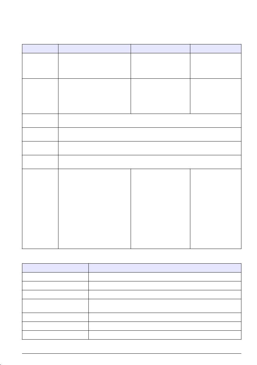
Specifications
Specifications are subject to change without notice.
SD900 Portable Sampler
Specification Standard base Compact base Composite base
Dimensions Diameter: 50.5 cm (19.9 in.)
Height: 69.4 cm (27.3 in.)
Weight 15 kg (35.6 lb) with 1-L
Enclosure Impact-resistant ABS, 3-section construction; double-walled base with 2.54 cm (1 in.)
Sample
temperature
Strainers 316 stainless steel in standard size, high velocity or low profile for shallow depth applications
Sample intake
tubing
Sample bottle
capacity
polyethylene bottles (24x)
14.8 kg (32.6 lb) with 10-L (2.5 gal)
polyethylene container (1x)
insulation—direct bottle contact with ice.
0–60 °C (32–140 °F)
and Teflon® or 316 stainless steel in standard size
9.5 mm (3/8 in.) I.D. vinyl or Teflon-lined polyethylene
1-L (0.26 gal) polyethylene and/or
350-mL (11.83 oz) glass bottles
(24x)
2.3-L (0.6 gal) polyethylene and/or
1.9-L (0.5 gal) glass bottles (8x)
3.8-L (1 gal) polyethylene and/or
3.8-L (1 gal) glass bottles (4x)
3.8-L (1 gal) polyethylene and/or
3.8-L (1 gal) glass bottles (2x)
21-L (5.5 gal) or 15-L (4 gal)
polyethylene composite container
or 20-L (5.25 gal) polyethylene or
10-L (2.5 gal) polyethylene or 10-L
(2.5 gal) glass (1x)
Diameter: 44.1 cm (17.4 in.)
Height: 61 cm (24 in.)
12.2 kg (27 lb) with 575-mL
(19.44 oz) polyethylene
bottles (24x)
12.9 kg (28.3 lb) with 10-L
(2.5 gal) polyethylene
container (1x)
575-mL (19.44 oz)
polyethylene bottles (24x)
950-mL (32.12 oz) glass
bottles (8x)
10-L (2.5 gal) polyethylene
bottle (1x)
10-L (2.5 gal) glass bottle
(1x)
Diameter: 50.28 cm
(19.8 in.)
Height: 79.75 cm
(31.4 in.)
15 kg (36 lb) with 950mL (32.12 oz) glass
bottles (12x)
21-L (5.5 gal)
polyethylene bottle (1x)
SD controller
Specification Details
Dimensions (W x H x D) 29.2 x 17.1 x 26.4 cm (11½ x 6¾ x 103/8 in.)
Weight 4.2 kg (9.26 lb)
Enclosure PC/ABS blend, NEMA 4X, 6, IP 67
Power requirements 15 VDC supplied by a 8754500 power supply; 15 VDC supplied by an integral
Overload protection 7 A, DC line fuse for the pump
Operating temperature 0 to 50 °C (32 to 122 °F)
Storage temperature –30 to 60 °C (–22 to 140 °F)
power supply
English 3
Page 6
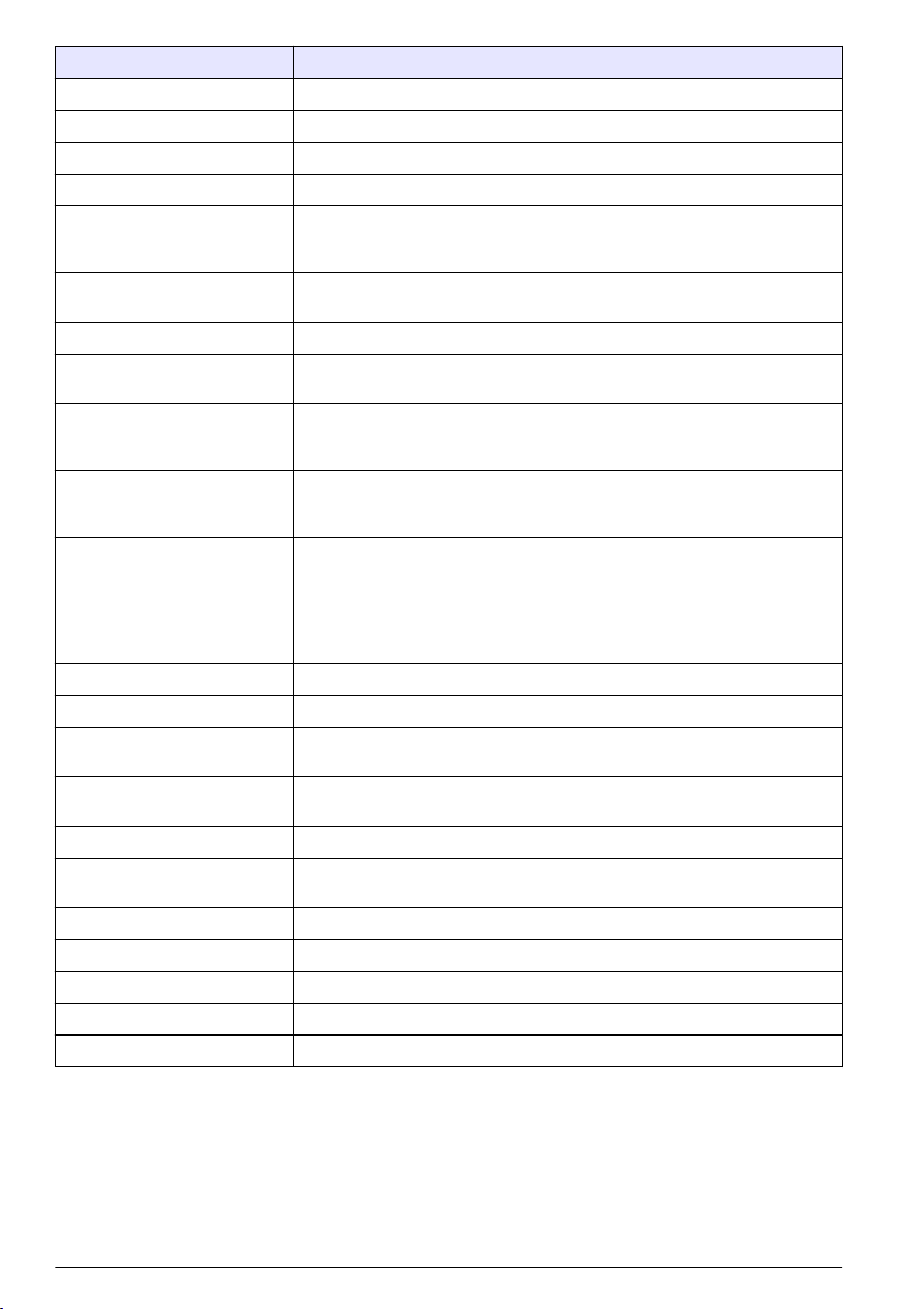
Specification Details
Storage/operating humidity 100% condensing
Pump Peristaltic high speed, with spring-mounted Nylatron rollers
Pump enclosure IP37
Pump tubing 9.5 mm ID x 15.9 OD mm (3/8 in. ID x 5/8 in. OD) silicone
Pump tubing life 20,000 sample cycles with: 1 L (0.3 gal) sample volume, 1 rinse, 6 minute
Vertical sample lift Maximum 8.5 m (28 ft) for: 8.8 m (29 ft) of 3/8-in. vinyl intake tube at sea level
Pump flow rate 4.8 L/min (1.25 gpm) at 1 m (3 ft) vertical lift with 3/8-in. intake tube typical
Sample volume Programmable in 10-mL (0.34 oz) increments from 10 to 10,000 mL (3.38 oz
Sample volume repeatability
(typical)
Sample volume accuracy
(typical)
Sampling modes Pacing: Time-fixed, flow-fixed, time-variable, flow-variable, constant time
Run modes Continuous or non-continuous with user-entered number of samples
Multiple programs Stores up to three sampling programs
Transfer velocity (typical) 0.9 m/s (2.9 ft/s) with: 4.6 m (15 ft) vertical lift, 4.9 m (16 ft) of 3/8-in. vinyl
Liquid sensor Ultrasonic. Body: Ultem® NSF ANSI standard 51 approved, USP Class VI
Sample history Up to 510 records
Air purge Air purged automatically before and after each sample. The duration
Event log 510 records
Connections Power, auxiliary, serial communications, distributor, SDI-12
Wetted materials Stainless steel, polyethylene, Teflon, Ultem, silicone
Communications RS232, Modbus, SDI-12
Warranty 1 year
pacing interval, 4.9 m (16 ft) of 3/8 in. intake tube, 4.6 m (15 ft) of vertical lift,
21 °C (70 °F) sample temperature
at 20–25 °C (68–77 °F)
to 2.6 gal)
±5% of 200 mL sample volume using uncalibrated liquid detect with: 4.6 m
(15 ft) vertical lift, 4.9 m (16 ft) of 3/8-in. vinyl intake tube, single bottle, full
bottle shut-off at room temperature and 1524 m (5000 ft) elevation
±10% of 200 mL sample volume using uncalibrated liquid detect with: 4.6 m
(15 ft) vertical lift, 4.9 m (16 ft) of 3/8-in. vinyl intake tube, single bottle, full
bottle shut-off at room temperature and 1524 m (5000 ft) elevation
variable volume (CTVV).
Refer to Constant Time Variable Volume (CTVV) sampling on page 23.
Distribution: Single bottle composite, multi-bottle composite, multi-bottle
discrete, bottles per sample, samples per bottle, combination of bottles per
sample, samples per bottle
intake tubing, 21 °C (70 °F) and 1524 m (5000 ft) elevation
compliant
automatically compensates for varying intake tube lengths.
General information
In no event will the manufacturer be liable for direct, indirect, special, incidental or consequential
damages resulting from any defect or omission in this manual. The manufacturer reserves the right to
make changes in this manual and the products it describes at any time, without notice or obligation.
Revised editions are found on the manufacturer’s website.
4 English
Page 7
Safety information
N O T I C E
The manufacturer is not responsible for any damages due to misapplication or misuse of this product including,
without limitation, direct, incidental and consequential damages, and disclaims such damages to the full extent
permitted under applicable law. The user is solely responsible to identify critical application risks and install
appropriate mechanisms to protect processes during a possible equipment malfunction.
Please read this entire manual before unpacking, setting up or operating this equipment. Pay
attention to all danger and caution statements. Failure to do so could result in serious injury to the
operator or damage to the equipment.
Make sure that the protection provided by this equipment is not impaired. Do not use or install this
equipment in any manner other than that specified in this manual.
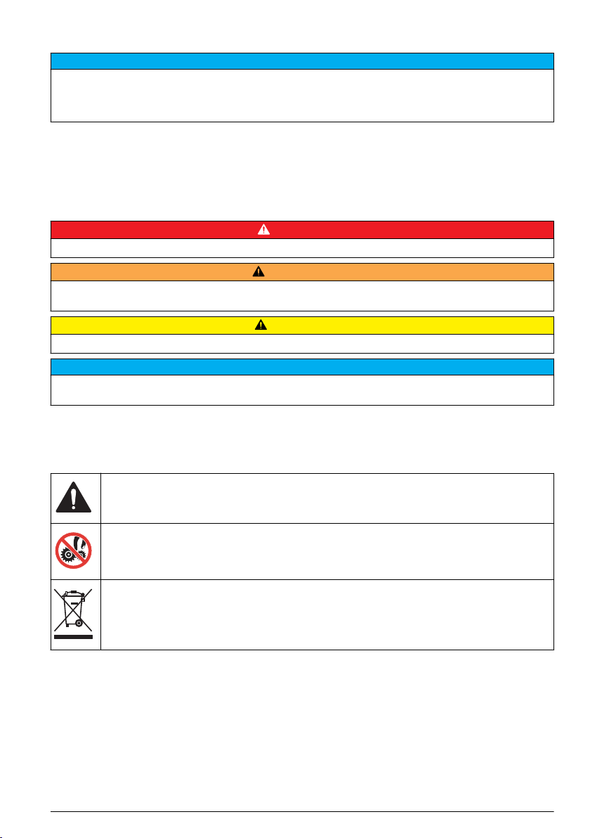
Use of hazard information
Indicates a potentially or imminently hazardous situation which, if not avoided, will result in death or serious injury.
Indicates a potentially or imminently hazardous situation which, if not avoided, could result in death or serious
injury.
Indicates a potentially hazardous situation that may result in minor or moderate injury.
Indicates a situation which, if not avoided, may cause damage to the instrument. Information that requires special
emphasis.
Precautionary labels
Read all labels and tags attached to the instrument. Personal injury or damage to the instrument
could occur if not observed. A symbol on the instrument is referenced in the manual with a
precautionary statement.
This is the safety alert symbol. Obey all safety messages that follow this symbol to avoid potential
injury. If on the instrument, refer to the instruction manual for operation or safety information.
D A N G E R
W A R N I N G
C A U T I O N
N O T I C E
This symbol indicates a potential pinch hazard.
Electrical equipment marked with this symbol may not be disposed of in European domestic or public
disposal systems. Return old or end-of-life equipment to the manufacturer for disposal at no charge to
the user.
Certification
Canadian Radio Interference-Causing Equipment Regulation, IECS-003, Class A:
Supporting test records reside with the manufacturer.
This Class A digital apparatus meets all requirements of the Canadian Interference-Causing
Equipment Regulations.
Cet appareil numérique de classe A répond à toutes les exigences de la réglementation canadienne
sur les équipements provoquant des interférences.
FCC Part 15, Class "A" Limits
English 5
Page 8
Supporting test records reside with the manufacturer. The device complies with Part 15 of the FCC
Rules. Operation is subject to the following conditions:
1. The equipment may not cause harmful interference.
2. The equipment must accept any interference received, including interference that may cause
undesired operation.
Changes or modifications to this equipment not expressly approved by the party responsible for
compliance could void the user's authority to operate the equipment. This equipment has been tested
and found to comply with the limits for a Class A digital device, pursuant to Part 15 of the FCC rules.
These limits are designed to provide reasonable protection against harmful interference when the
equipment is operated in a commercial environment. This equipment generates, uses and can
radiate radio frequency energy and, if not installed and used in accordance with the instruction
manual, may cause harmful interference to radio communications. Operation of this equipment in a
residential area is likely to cause harmful interference, in which case the user will be required to
correct the interference at their expense. The following techniques can be used to reduce
interference problems:
1. Disconnect the equipment from its power source to verify that it is or is not the source of the
interference.
2. If the equipment is connected to the same outlet as the device experiencing interference, connect
the equipment to a different outlet.
3. Move the equipment away from the device receiving the interference.
4. Reposition the receiving antenna for the device receiving the interference.
5. Try combinations of the above.
Product overview
D A N G E R
Chemical or biological hazards. If this instrument is used to monitor a treatment process and/or
chemical feed system for which there are regulatory limits and monitoring requirements related to
public health, public safety, food or beverage manufacture or processing, it is the responsibility of the
user of this instrument to know and abide by any applicable regulation and to have sufficient and
appropriate mechanisms in place for compliance with applicable regulations in the event of malfunction
of the instrument.
C A U T I O N
Fire hazard. This product is not designed for use with flammable liquids.
The SD900 Portable Sampler collects liquid samples at specified intervals and keeps the samples in
bottles or containers. Use the sampler for a wide variety of aqueous applications and for toxic
pollutants and suspended solids. Set up
the sampler with different retainers, bottles or containers.
Refer to Figure 1.
6 English
Page 9
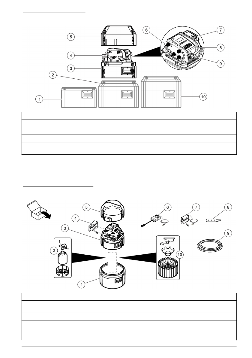
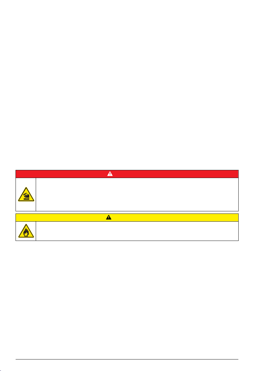
Figure 1 Product overview
1 Compact base 6 Controller connections
2 Standard insulated base 7 Pump
3 Center section 8 Controller
4 Power source 9 Liquid sensor
5 Top cover 10 Standard insulated base for 21-L (5.5 gal)
container
Product components
Make sure that all components have been received. Refer to Figure 2. If any items are missing or
damaged, contact the manufacturer or a sales representative immediately.
Figure 2 Product components
1 Base (Standard, compact or composite) 6 Battery charger (optional)
2 Components for a single-bottle option (bottle and
support can change)
3 Center section with controller 8 Strainer
4 Battery (optional) 9 Intake tubing, vinyl or Teflon-lined
5 Top cover 10 Components for a multiple-bottle option (bottles
7 AC power supply (optional)
and retainers can change)
English 7
Page 10
Installation
D A N G E R
Multiple hazards. Only qualified personnel must conduct the tasks described in this section of the
document.
Confined space precautions
D A N G E R
Explosion hazard. Training in pre-entry testing, ventilation, entry procedures, evacuation/rescue
procedures and safety work practices is necessary before entering confined spaces.
The information that follows is supplied to help users understand the dangers and risks that are
associated with entry into confined spaces.
On April 15, 1993, OSHA's final ruling on CFR 1910.146, Permit Required Confined Spaces, became
law. This standard directly affects more than 250,000 industrial sites in the United States and was
created to protect the health and safety of workers in confined spaces.
Definition of a confined space:
A confined space is any location or enclosure that has (or has the immediate potential for) one or
more of the following conditions:
• An atmosphere with an oxygen concentration that is less than 19.5% or more than 23.5% and/or a
hydrogen sulfide (H2S) concentration that is more than 10 ppm.
•
An atmosphere that can be flammable or explosive due to gases, vapors, mists, dusts or fibers.
• Toxic materials which upon contact or inhalation can cause injury, impairment of health or death.
Confined spaces are not designed for human occupancy. Confined spaces have a restricted entry
and contain known or potential hazards. Examples of confined spaces include manholes, stacks,
pipes, vats, switch vaults and other similar locations.
Standard safety procedures must always be obeyed before entry into confined spaces and/or
locations where hazardous gases, vapors, mists, dusts or fibers can be present. Before entry into a
confined space, find and read all procedures that are related to confined space entry.
Mechanical installation
Site installation guidelines
D A N G E R
Explosion hazard. The instrument is not approved for installation in hazardous locations.
Refer to the guidelines that follow for the site location evaluation.
• Obey all the safety precautions if the sampler is installed in a confined space. Refer to Confined
space precautions on page 8.
• Make sure that the temperature at the location is in the specification range. Refer to Specifications
on page 3.
• Install the sampler on a level surface or hang the sampler with the suspension harness, the
support bracket or the spanner bar. Refer to Install the sampler in a manhole on page 9 and to
the applicable installation documentation.
• As near the sample source as possible to decrease analysis delay. Refer to Plumb the sampler
on page 11.
• For limitations on transport velocity and maximum vertical lift, refer to Specifications on page 3.
8 English
Page 11
Install the sampler in a manhole
Install the sampler above the sample water in a manhole. Install the sampler
support bracket. Install the spanner bar inside the manhole. The spanner bar is supported by
pressure against the walls. The support bracket has the same width as the manhole cover. Install the
support bracket directly below the cover for support. Refer to Replacement parts and accessories
on page 42. Refer to the documentation supplied with the accessories to install the sampler.
with a spanner bar or a
Install the distributor or full-bottle shutoff (optional)
The distributor or full-bottle shutoff assembly is typically installed at the factory. Refer to the
distributor or full-bottle shutoff documentation for installation.
Prepare the sampler
Clean the sample bottles
Clean the sample bottles and caps with a brush, water and a mild detergent. Flush the containers
with fresh water followed by a distilled water rinse.
Install a single bottle
Use a single bottle to collect one composite sample. When the bottle is full, the full bottle shut-off
stops the sample program.
1. Clean the sample bottles. Refer to Clean the sample bottles on page 9.
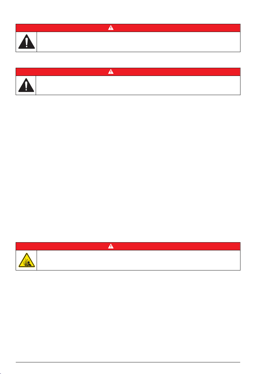
2. Install the sample bottle as shown in Figure 3.
Figure 3 Single bottle installation
1 Polyethylene bottle, 10 L (2.5 gal) (1918) 6 Polyethylene bottle, 21 L (5.5 gal) (6494)
2 Glass bottle, 10 L (2.5 gal) (6559) 7 Compact base (8975)
3 Support (1502) 8 Standard insulated base (8976)
4 Polyethylene bottle, 15 L (4 gal) (1367) 9 Standard insulated base for 21 L (5.5 gal) bottle
5 Polyethylene bottle, 19 L (5 gal) (6498)
(8561)
Install the first bottle for multiple sample collections
Use multiple bottles to collect samples into separate bottles or into more than one bottle. The
distributor moves the sample tube above each bottle. Install the bottles in the sampler base as shown
in Figure 4. Install the first sample bottle (number 1) below the label in the sampler base. Install the
remaining bottles in increasing numbers in the direction shown by the label. Refer to Figure 5
on page 11 for a diagram of necessary components.
9
English
Page 12
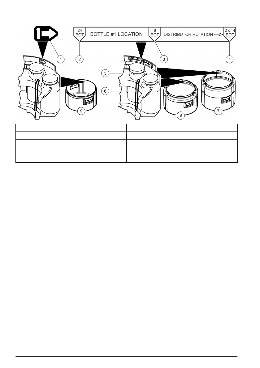
Figure 4 Bottle number 1 installation
1 Bottle number 1 location (compact base) 6 Elastic straps
2 Bottle number 1 location for 24 bottles 7 Standard insulated base for 21 L (5.5 gal) bottle
3 Bottle number 1 location for 8 bottles 8 Standad insulated base
4 Bottle number 1 location for 2 or 4 bottles 9 Compact base
5 Retainer
Install multiple bottles
When multiple bottles are installed, a distributor arm moves the sample tube over each bottle.
Sample collection automatically stops when the specified number of samples have been collected.
1. Clean the sample bottles. Refer to Clean the sample bottles on page
9.
2. Install the first sample bottle (number 1) below the label in the sampler base. Refer to Install the
first bottle for multiple sample collections
on page 9.
3. Assemble the sample bottles as shown in Figure 5. For eight or more bottles, make sure that the
first bottle goes next to the bottle one indicator in the clockwise direction.
4. Put the bottle assembly in the sampler. For eight or more bottles, align the wires in the slots in the
bottom tray.
10 English
Page 13
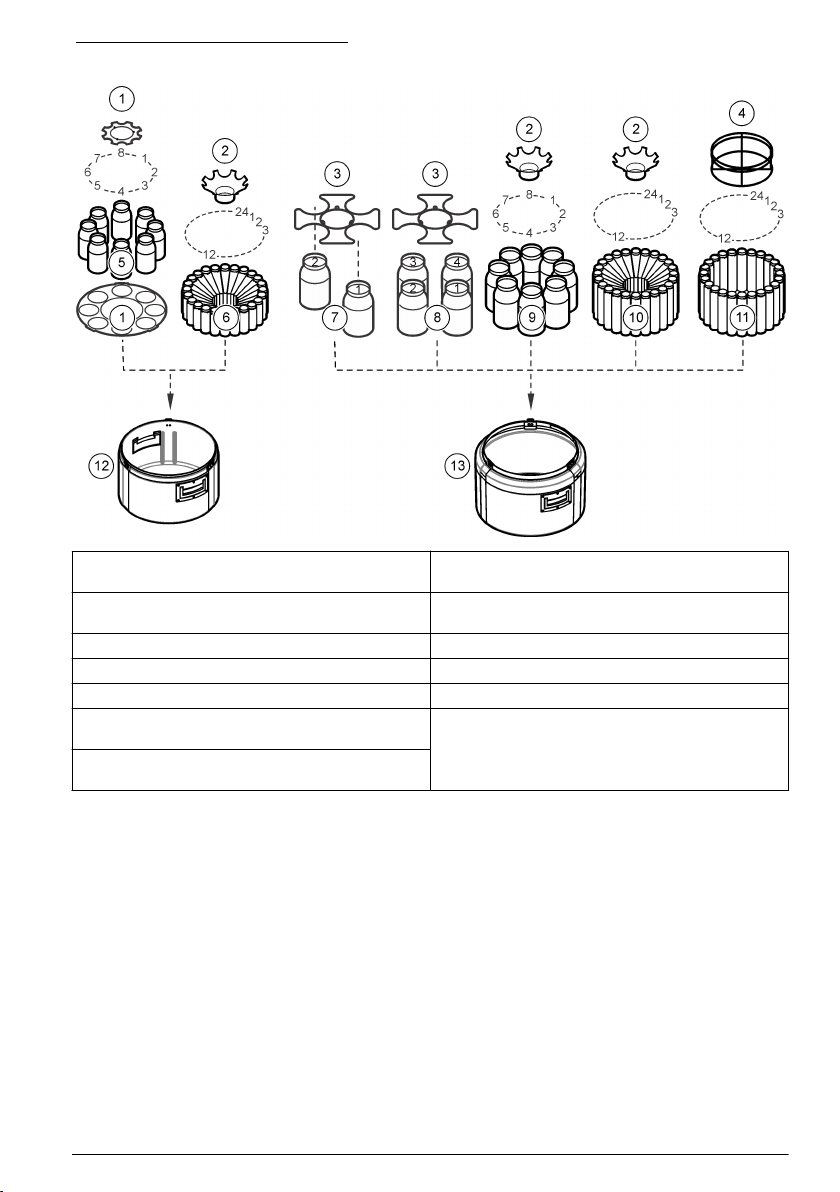
Figure 5 Multiple bottle installation
1 Positioner/retainer (2347) 8 Glass bottles, 3.8 L (1 gal), (4x) (2216) or
2 Retainer (1422) 9 Glass bottles, 1.9 L (0.5 gal), (8x) (1118) or
3 Retainer (2190) 10 Polyethylene bottles, 1 L (0.26 gal), (24x) (737)
4 Retainer (2189) 11 Glass bottles, 350 mL (11.83 oz), (24x) (732)
5 Glass bottles, 950 mL (32.12 oz) (8x) (2348) 12 Compact base (8975)
6 Polyethylene bottles, 575 mL (19.44 oz), (24x)
(1369)
7 Glass bottles, 3.8 L (1 gal), (2x) (2214) or
polyethylene bottles, 3.8 L (1 gal), (2x) (2215)
polyethylene bottles, 3.8 L (1 gal), (4x) (2217)
polyethylene bottles, 2.3 L (0.61 gal), (8x) (657)
13 Standard base (8976)
Plumb the sampler
Install the strainer in the middle of the sample stream (not near the surface or the bottom) to make
sure that a representative sample is collected. Refer to Figure 6. Refer to Figure 7 for the intake tube
installation.
1. Connect the tubing to the sampler as shown in Figure 7.
Note: Use connection kit 2186 if Teflon-lined tubing is used.
2. Install the intake tube and strainer in the main stream of the sample source where the water is
turbulent and well-mixed.
• Make the intake tube as short as possible.
•
Keep the intake tube at a maximum vertical slope so that the tube drains completely between
samples.
Note: If a vertical slope is not possible or if the tube is pressurized, disable the liquid sensor. Calibrate the
sample volume manually. Refer to Calibrate the sample volume manually on page 28.
• Make sure that the intake tube is not pinched.
English 11
Page 14
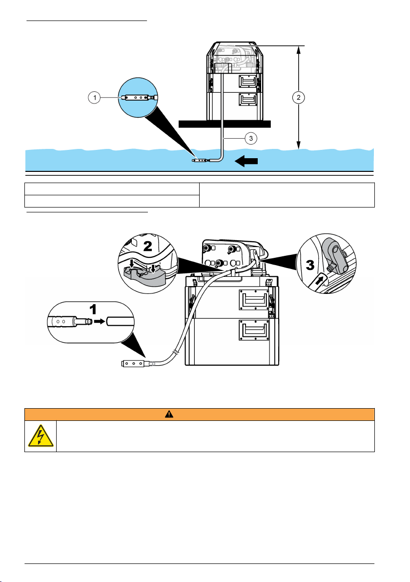
Figure 6 Instrument installation
1 Strainer 3 Intake tube
2 Vertical lift
Figure 7 Intake tube installation
Electrical installation
Controller connections
W A R N I N G
Electrical shock hazard. Externally connected equipment must have an applicable country safety
standard assessment.
Figure 8 shows the connections that can be made to the controller.
12 English
Page 15
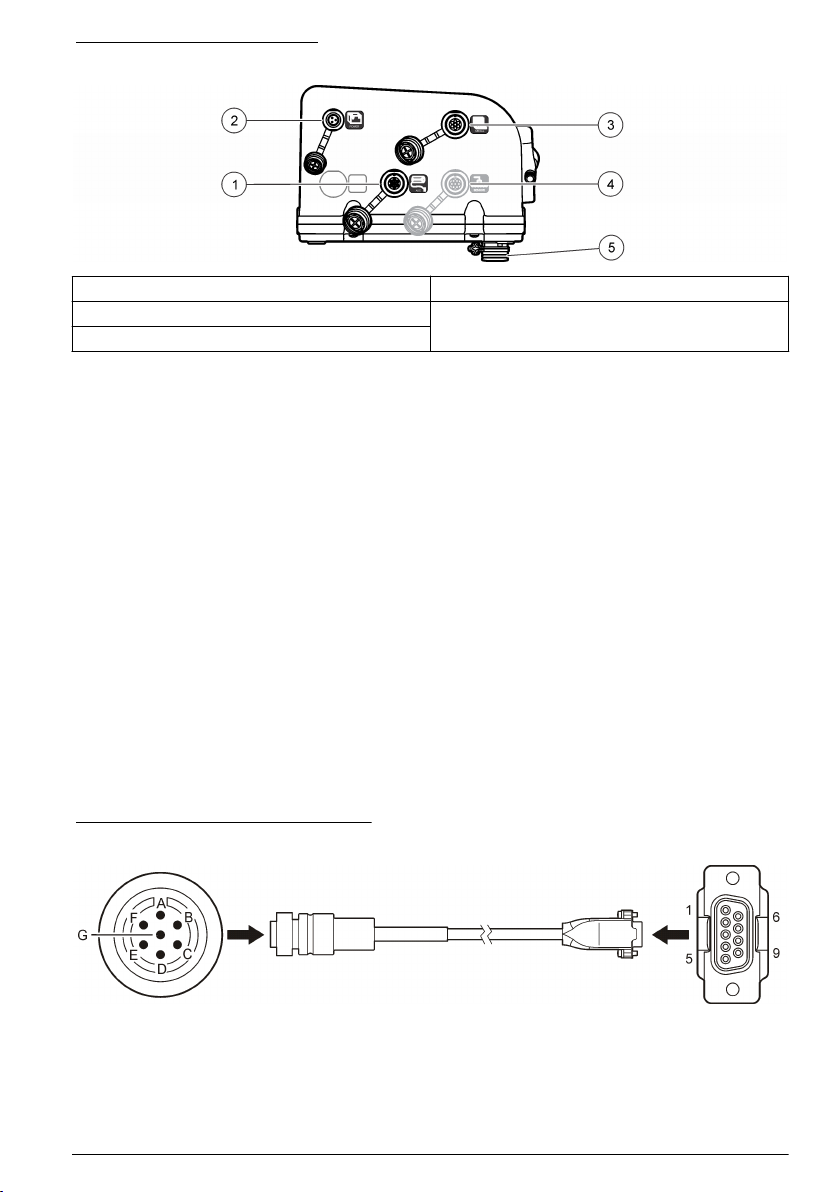
Figure 8 Controller connectors
1 Auxiliary device 4 SDI-12 device option
2 Power supply 5 Distributor/full bottle shut-off
3 Serial communications
Connect a flow meter
Connect a flow meter to the controller to start or stop the sampler when the sample flow goes above
or below a specified value.
Items to collect:
• Multi-purpose full cable for Sigma flow meters (or 980 half cable for the model 980 flow meter).
•
Optional splitter for additional connections. Two or more splitters can be connected in series.
1. Connect one end of the cable to the flow meter. For the model 980 flow meter, refer to the model
980 flow meter user manual.
2. Connect the other end of the cable to the auxiliary device connector on the controller.
Note: If the flow meter has a 6-pin cable, use the 6-pin to 7-pin adapter cable.
Connect a PC or communications network
Connect a PC or a communications network to the controller to transfer data or to configure the
sampler.
Items to collect:
• Serial cable, 7-pin RS232 to DB-9 (refer to Figure 9). Connections: B to 5 (signal ground); D to
3 (RCD); F to 2 (TXD); G (ground).
1. Connect one end of the serial cable to the communications device or network.
2. Connect the other end of the cable to the serial communications connector on the controller.
Figure 9 Serial communications cable
English 13
Page 16

Connect an SDI-12 device
N O T I C E
Measurement errors can occur due to electrical transients from sources such as lightning or large electrical
motors. These errors can cause unexpected sample acquisition or a missed sample when the controller is
programmed for setpoint sampling based on sonde measurements. Use a power line filter or connect the
controller to a different branch circuit to reduce the possibility of transients.
The controller supplies power to the SDI-12 device. Use the 15 m (50 ft) cable or the 30 m (100 ft)
cable to connect a sonde to the controller. Refer to Figure 10.
Note: A separate power supply for the sonde is necessary for data logging by the sonde.
The SDI-12 interface is enabled only when a connected device is found by the controller. The scan
for a sensor occurs automatically. The address that is assigned to the SDI-12 device is automatically
detected by the controller.
Figure 10 Sonde connection
1 Sonde 4 SDI-12 connector
2 Sonde bulkhead connector 5 15 or 30 m (50 or 100 ft) cable
3 6-pin cable connector
Connect the sampler to power
Electrocution hazard. If this equipment is used outdoors or in potentially wet locations, a Ground Fault
Circuit Interrupt (GFCI/GFI) device must be used for connecting the equipment to its main power
source.
Fire hazard. Install a 15 A circuit breaker in the power line. A circuit breaker can be the local power
disconnect, if located in close proximity to the equipment.
Electrocution hazard. Protective Earth Ground (PE) connection is required.
Electrocution hazard. Make sure that there is easy access to the local power disconnect.
14 English
D A N G E R
D A N G E R
D A N G E R
W A R N I N G
Page 17

W A R N I N G
Electric shock hazard. The power supply can overheat when the time between pump cycles is too
short.
N O T I C E
Make sure that the pump cycle time will not cause the power supply to overheat. Refer to Calculate the pump
cycle time on page
15.
Connect the sampler to a battery or to an AC power supply. Refer to the illustrated steps that follow.
Calculate the pump cycle time
The pump must stay off for a minimum time period between sample cycles so that the power supply
does not overheat.
1. Calculate the total amount of time that the pump will run continuously during a sample cycle.
Include all stages: pre-purge, intake rinse, sample, sample retries and post-purge.
2. Find the minimum amount of time that the pump must stay off between sample cycles from
Figure 11.
3. Make sure that the pacing or time interval in the sampler program lets the pump stay off between
sample cycles for the minimum amount of time.
English 15
Page 18

Figure 11 Pump on and off times at 50 °C (122 ºF)
1 Time (in minutes) that the pump must stay off 3 Example: if the pump is on continuously for
2 Time (in minutes) that the pump is on continuously
5 minutes, the pump must stay off for 15 minutes.
Close the cover
To close the cover, align the latch plates as shown in Figure 12 and close the latches.
Figure 12 Latch plates alignment
Set the power to on
Push the power button to set the power to on or off. Make sure that the power supply (AC power or
battery power) is correctly installed.
User interface and navigation
The controller keypad is shown in Figure 13. Use the MENU key to set up sampling programs,
configure the controller settings or complete the diagnostic tests. Use the arrows, ENTER and BACK
keys to scroll through the menu, make selections and enter values. Look for arrows on the bottom or
side of the display screen to know when more options are available.
16 English
Page 19

Figure 13 Controller keypad
1 POWER 5 MENU 9 STATUS
2 VOLUME CALIBRATION 6 ENTER 10 RUN/HALT PROGRAM
3 STOP 7 BACK 11 MANUAL OPERATION
4 LED 8 ARROW KEYS
Operation
Main menu overview
The main menu contains four options for sampler operation, monitoring or data management.
Table 1 Sampler menu overview
Menu option Description
Program setup Create, review or set up a sampling program
Status Display the status of the current program
Diagnostics Review and manage data or test the operation of components
System setup Change the controller settings or calibrate the liquid sensor
Configure the system settings
1. Push MENU.
2. Go to SYSTEM SETUP.
3. Change the applicable options.
Option Description
Time/date setup Set the time (24-hour format) and date.
Communication Select the baud rate (19200, 38400, 57600 or 115200) and protocol (Modbus RTU or
ASCII) for the serial port.
English 17
Page 20

Option Description
Setup base Select the sampler base (All weather refrigerated, refrigerated, portable standard or
Language Select the language of the controller.
Liq sensor cal Calibrate the liquid sensor or set to default.
Set contrast Adjust the contrast of the LCD screen.
Pump duty cycle Change the pump duty cycle. Range: 50% to 100% (default: 100%).
Password setup Set up a password to control access to the program setup and the system setup menus.
Tubing life Set a reminder when the pump tubing is to be changed. Go to ENABLE>RESET
SDI–12 (optional) Configure the operation of an SDI–12 device. This option is shown only when a device is
portable compact).
Select ENABLE>YES to set a new password or ENABLE>NO to activate the current
password. If the password is set for the first time, use 900900 as the current password.
CYCLES to reset the pump cycle count to 0. Go to ENABLE>CYCLE LIMIT to change
the number of pump cycles that is used for the reminder. Go to ENABLE>STATUS to
show the current number of pump cycle counts.
found.
Configure the SDI-12 device
A sensor such as a sonde can connect to the optional SDI-12 interface. The controller can get up to
nine measurements from one SDI-12 sensor. The sensor data can then be used as a trigger in
setpoint sampling applications. Configure the parameter type and unit, and set how often the
SDI-12 device is scanned for new measurement data.
1. Select Menu>System Setup>SDI-12.
Note: The SDI-12 option is only shown when an SDI-12 device is found by the controller.
2. Select one of the options:
Option Description
DISPLAY SONDE Shows information about the device such as the vendor name, model name,
CFG PARAMETERS Gives a name and measurement unit to the SDI-12 channel. Each channel is initially
SCAN INTERVAL Sets the time interval when measurement data is refreshed in the controller. Short
SDI-12 address, protocol version, number of available measurements and the warmup time.
shown with a generic reference indicator in the same order that is set in the
SDI-12 device. Table 2 shows the measurements that are supported by the controller.
Note: It may be necessary to configure the SDI-12 interface for the sonde.
time intervals decrease the battery life.
Dissolved oxygen (DO) mg/L, % saturation x.xx
18 English
Table 2 Supported measurements
Measurement Unit Resolution
Ammonia (NH3) mg/L-N x.xx
Ammonium (NH4+) mg/L-N, mV x.xxxx
Chloride (Cl-) mg/L-N, mV x.xxxx
Chlorophyll µg/L, V x.xx
Conductivity mS/cm, µS/cm x.xxx
Ext. Sonde Pwr V, % x.xxxx
HOCl ppm, V x.xxxx
1
Page 21

Table 2 Supported measurements (continued)
Measurement Unit Resolution
Int. Sonde Pwr V, % x.xxxx
Level m, ft, psi x.xxx
NH3+NH4 mg/L-N x.xxxx
Nitrate (NO3-) mg/L-N, mV x.xx
ORP mV x
PAR µE/S/n2 x.xxxx
pH pH unit x.xx
Phycocyanin cells/mL, mV x.xx
Phycoerythrin cells, mV x.xx
raw TDG mV x.xxxx
ref PAR µE/S/n2 x.xxxx
Resistivity kΩ/cm x.xxx
Rhodamine ppb, V x.xx
Salinity ppt x.xxxx
Total Dissolved Solids g/L x.xx
Temperature C, F, K x.xx
Total Dissolved Gas mmHg, psi x.xxxx
Transmission %, V, %660 nm, v660 nm x.xxxx
Turbidity NTU, V x.x
1
The number of decimal places shown on the controller display
1
Set up a sampling program
A sampling program includes all of the parameters that are necessary to collect samples
automatically. Collect the samples at regular intervals or when the sampling program is complete.
1. Push MENU.
2. Go to PROGRAM SETUP>MODIFY ALL. The first screen is shown.
3. Select or enter the values for each parameter. Use the left and right arrow keys to move left or
right. Use the up and down arrow keys to change a value. Change the units if necessary (gal or
mL) with the arrow keys.
Option Description
Bottles Bottle quantity: the number of bottles in the sampler (1, 2, 4, 8 or 24).
Full BTL shutoff: Enabled/Disabled. If enabled, the controller checks for bottle
overflow conditions.
Bottle volume: the volume capacity of each bottle. Range: 50–65000 mL (0.01 -
17.17 gal)
English 19
Page 22

Option Description
Intake tubing Tubing length: the length of the intake tubing from the strainer to the liquid sensor.
Range: 100–3000 cm or 3–99 ft. An accurate length is necessary to get an accurate
sample volume.
Intake tube type: the diameter and material of the intake tubing (¼ in. vinyl, 3/8 in.
vinyl or 3/8 in. Teflon).
Program delay Enable/disable: when enabled, the sampling program starts at a specified time or
number of counts. Date and time: the date and time when the program starts (24hour format). Counts: the number of counts or pulses from a flow meter when the
program will start (1 to 9999 counts). If the sample pacing is later set to time, the
program delay will be disabled.
Sample
pacing/collection
Time based—Refer to Time based collection on page 21.
Note: When CTVV is used:
• The liquid sensor is always enabled.
• The sample distribution is composite.
• The run mode is non-continuous.
• The first sample is taken after the interval.
• Flow source is always 4–20 mA input.
Flow based—Refer to Flow based collection on page 21.
Sample distribution Deliver samples to all>YES
Each sample is delivered to all bottles. End after last: program stops after the last
sample (1–999). Continuous: program continues until it is stopped manually.
Deliver samples to all>NO
Samples are delivered to a subset of bottles (Figure 14). Samples/bottle: the number
of samples to be collected in each bottle (1–999). Bottles/sample: The number of
bottles that will contain the same sample.
Liquid sensor Enable or disabled. If disabled, the sample volume must be calibrated by time.
Sample volume The volume of each sample in mL (1 gal = 3785.4 mL). If bottles/sample mode is
used, each bottle receives a full sample volume (10–10,000 mL). Make sure that the
sample volume does not exceed the bottle volume. Sample volumes are rounded to
the nearest 10 mL.
Intake rinses The number of intake tube rinses before a sample is collected (0–3).
Sample retries The number of sampling tries after a sampling failure occurs (0–3).
Site ID The name for the sampling location (up to 12 characters). The site ID is used as the
preset name if the program is saved.
Advanced sampling Goes to the advanced sampling menu. If necessary, configure the options in the
Advanced Sampling menu.
Run program The creation of the basic sampling program finishes. The sampler prompts the user
to start or cancel the program.
Figure 14 Two samples per bottle (left) versus two bottles per sample (right)
20 English
Page 23

Time based collection
1. Select or enter the values for each option.
Option Description
Pacing interval Collect samples at regular time intervals, in hours and minutes (0:01–999:00).
Take first sample The program starts immediately or after the first interval.
Variable volume Specify whether the sample volumes vary (flow based). If yes, refer to Use variable
Use variable volume
Sample pacing is constant time variable volume (CTVV).
1. Select or enter the values for each option.
Option Description
Select unit Select the flow units to use.
Map 4 mA input Enter the flow rate that agrees with 4 mA input.
Map 20 mA input Enter the flow rate that agrees with 20 mA input.
Average flow rate Specify the average flow rate for the site (1–999,999). The units are specified by
Time volume desired Specify the total volume to be collected during the sample program
Collection period Specify the total collection period in hours and minutes (0:01–999:00).
Minimum sample volume If the flow volume is not sufficient to collect this minimum volume, the sample is
volume on page 21. If no, refer to Do not use variable volume on page 21.
the units selected above.
(10–10,000 ml).
skipped (10–10,000 ml).
Do not use variable volume
1. Select or enter the values for the option.
Option Description
Take first sample Select whether the program starts immediately or after the first time interval has passed.
Flow based collection
Specify the flow source for flow based sampling:
• Counts—Refer to Use counts for the flow source
• 4–20 mA input—Refer to Use 4–20 mA input for the flow source on page 22.
Use counts for the flow source
1. Select or enter the values for each option.
Option Description
Take sample every Collect samples at regular flow intervals, in counts (1–9999 counts).
Overrride time Collect a sample if the flow volume is very low.
on page 21.
English 21
Page 24

Option Description
Time The maximum time between samples (0:01–999:00). The timer starts again after each
Take first sample The program starts immediately or after the first time interval.
sample is collected.
Use 4–20 mA input for the flow source
1. Select or enter the values for each option.
Option Description
Select unit Selects the flow units to use.
Map 4 mA input Enter the flow rate that would agree with the 4 mA input.
Map 20 mA input Enter the flow rate that would agree with the 20 mA input.
Take sample every Enter the total flow after which the sample has to be drawn.
Override time Select enable to push a sample to be collected if the flow volume is unusually low.
Time The maximum time between samples (0:01–999:00). The timer starts again after each
Sample volume Enter the volume to be collected per sample. If bottles/sample mode is selected, each
sample is collected.
bottle receives a full sample volume (100–10,000 mL). This option is skipped if variable
volume is selected.
Review or modify program settings
To review or change Individual settings for an existing sampling program:
1. Push MENU.
2. Go to PROGRAM SETUP. Select one of the options.
Option Description
Modify selected Change any of the program settings.
Review Review the program settings.
Save or load programs
Up to three sampling programs can be saved as presets for later use. If any changes are made to a
preset program after it is loaded, the program must be saved again to keep the changes.
1. Push MENU.
2. Go to PROGRAM SETUP>PRESETS.
3. Select one of the preset numbers (P1, P2 or P3).
Note: If a program is already stored, the site ID for that program is shown to the right of the preset number. If
no program is stored, the preset field is empty.
4. Select one of the options.
Option Description
STORE CURRENT Store the current program as a preset.
LOAD PROGRAM Open the selected preset program.
Restore the default settings
The restore option sets all of the program parameters to the default settings.
22 English
Page 25

1. Push MENU.
2. Go to PROGRAM SETUP>RESTORE.
3. Select YES.
Constant Time Variable Volume (CTVV) sampling
CTVV samples are taken at user-specified constant (fixed) time intervals. However, the actual
volume of each sample is based on the:
• Known average flow rate of the site
•
Actual metered flow rate at the time of sampling
• Total sample volume desired
• User-specified collection period
• Specified sampling interval
The volume of individual sampling can vary and depends on the flow volumes of the stream at
various intervals within the collection period. The total sample collected during the entire period can
be slightly above or below the necessary total volume. For these reasons, the manufacturer
recommends that a sampling container is used that has a larger volume than the necessary total
volume. When CTVV is used for sampling:
• Sample distribution menus are not available when CTVV is selected, only composite sampling is
supported.
• The liquid sensor is always enabled.
• The sample distribution is composite.
• The run mode is non-continuous.
• The first sample is taken after the interval.
• Flow source is always 4–20 mA input.
The instrument finds the sample volume, based on user inputs and actual metered flow volume. For
example, the entered values are:
• Average flow rate (historical, site specific): 150 gph
• Sampling interval: 2 minutes
• Total sample volume desired: 1500 mL
• Collection period: 30 minutes
Calculation 1: Total number of samples
Collection period ÷ Sampling interval = 30 minutes ÷ 2 minutes = 15 samples
Calculation 2: Average sample volume
Total sample volume desired ÷ Total number of samples = 1500 mL ÷ 15 Samples = 100 mL/sample
Calculation 3: Sample volume per unit of flow rate
Average sample volume ÷ Average flow rate = (100 mL/sample) ÷ 150 gph = 0.66 mL/gph
Calculation 4: Collect actual sample volume
• If the 4–20 mA flow source is used and the flow rate measured is 140 gph, use sample volumes
per unit of flow rate x actual metered flow rate.
0.66 mL/gph x 140 gph = 92.4 mL. The sampler will pull a 90 mL sample (rounded off from
92.4 mL).
• If the flow pulses are used and every pulse count is 2 gallons and 2 counts are received in
2 minutes, the flow rate is 120 gph.
Sample volumes per unit of flow rate x actual metered flow rate
0.66 mL/gph x 120 gph = 79.2 mL. The sampler will pull a 80 mL sample (rounded off from
79.2 mL).
English 23
Page 26

Start or stop a program
Use the RUN/HALT PROGRAM key to start or stop a program. Up to 12 user-defined start/stop
times/dates can be set. A program must be stopped before the program or system setup can be
changed.
The status reads RUNNING (while a program runs) or HALTED (when temporarily stopped by the
user). Use the RIGHT arrow to get information about the program while it runs.
• Power supply voltage
•
Inhibit mode (none, setpoint trigger, program delay, user start, storm trigger, full bottle and setpoint
delay)
• Sample summary (number of samples tried, missed and remaining)
• Next sample information (sample number and the bottle number of the next sample)
• Flow information when variable volume is enabled (current flow and the flow since the program
started)
• Time before the next sample
• Program the start time
1. Push RUN/HALT PROGRAM.
2. Select one of the options.
Option Description
Start Starts the currently loaded program. The status changes to RUNNING.
Halt Stops the program temporarily. The status changes to HALTED.
Resume The program resumes from the point at which it was halted. The status changes to
Start over The program starts from the beginning. The status changes to RUNNING.
End program Stops the currently running program. The status changes to COMPLETE.
RUNNING.
View the program status
The current status of main and/or stormwater programs and of SDI-12 measurements can be shown.
1. Push STATUS or select STATUS from the main menu.
2. If multiple programs are in operation, select one of the programs. The program status is shown.
3. Review the program status. Push the right arrow to see additional information.
Status Description
READY The program is ready to start. The power supply voltage and the current time are shown.
RUNNING The program is in operation.
HALTED The program was stopped temporarily by the user.
COMPLETE All of the programmed sample cycles are complete, or the program was stopped by the user.
Manual operation
Use manual operation to collect a grab sample, move the distributor arm or operate the pump.
Collect a grab sample
Collect a grab sample to make sure that the sample volume is correct or to bypass the sample
program.
1. Put the tubing from the outlet side of the pump into a sample container.
2. Put the intake tubing into the sample water.
24 English
Page 27

3. Push MANUAL OPERATION.
4. Select GRAB SAMPLE.
5. Enter the volume to collect and push ENTER.
Note: The grab sample volume can only be changed if the liquid sensor is enabled.
The intake tubing is purged and then the specified volume of sample is collected. The intake tube
is purged again.
Move the distributor arm
Move the distributor arm manually to put a grab sample in a specific bottle or to make sure that the
distributor arm position is correct.
1. Push MANUAL OPERATION.
2. Select MOVE DISTRIB. The current bottle number is shown.
3. Enter the number of the bottle over which the distributor arm will be moved.
4. Push ENTER. The distributor arm moves to the selected bottle.
Note: To stop the distributor arm at any time, push STOP.
Start or stop the pump
The pump can be operated manually to collect a sample or purge the intake tubing.
1. Push MANUAL OPERATION.
2. Select OPERATE PUMP.
3. Select the direction:
Option Description
Run forward The pump operates in the forward direction to collect a sample and deposit the sample in a
Run backward The pump operates in the reverse direction to purge the intake tubing.
4. Push STOP to stop the pump.
sample container.
View data
Data can be viewed from one of the status screens or from the diagnostics menu.
View the sample history
The sample history shows the sample number, bottle number, sample volume, result and time/date
for each sample.
get the additional information, download the sample history with the SampleView program. If a
program is in operation or has been halted, the sample history is shown for the current program. If
the program is complete, the sample history is shown for the most recently completed sampling
program. The sample history is automatically erased when a new program is started.
The following results can be shown:
• Success—the sample was drawn successfully.
• Bottle full—the full bottle shut-off was activated.
• Rinse error—an error occurred during the rinse cycle.
• User abort—a user pushed the STOP key to end the sample cycle.
• Arm faulty—the distributor arm did not move correctly.
• Pump fault—a fault occurred when the pump was operating.
• Purge fail—an error occurred during the purge cycle.
• Sample time out—liquid was not detected within the timeout period.
• Power fail—a power failure occurred during sampling.
• Low flow—sample was missed due to insufficient flow.
Flow information is recorded when a sampler program is run with CTVV pacing. To
English 25
Page 28

1. Select DIAGNOSTICS>SAMPLE HISTORY from the main menu to view the sample history.
2. The sample history shows the sample numbers, bottle numbers and brief result for each sample.
Select a sample from the list and push ENTER to view the complete details.
View the event log
View the event log to see details about the events that have been recorded.
1. Go to DIAGNOSTICS>EVENT LOG.
2. Select DISPLAY. The event log shows the date and event.
3. Select an event from the list, then push ENTER to see the complete details.
The top bar shows the event number and the total number of events in the event log. For
example, 01/80 will be shown for event number 1 and a total number of 80 events. The time/date,
event description and any additional data for the selected event is shown.
Event log information
The event log records information on these events:
•
Power on—power was connected to the controller.
• Power fail—power was intentionally or unintentionally disconnected from the controller without first
turning the power off.
• Firmware update—a new version of firmware was installed.
• Pump fault—a fault occurred when the pump was operating.
• Arm faulty—the distributor arm did not move correctly.
• Low memory battery—the internal battery should be replaced.
• User on—a user turned the power on using the power key.
• User off—a user turned the power off using the power key.
• Program start—the sample program was started.
• Program resume—a program was resumed from the halt state.
• Program halt—a program was halted.
• Program complete—a program was completed.
• Grab sample—a grab sample was taken.
• Change tube—the maximum pump cycle counts have expired.
• SDI-12 timeout—indicates a communication error on the SDI-12 interface.
• High setpoint on—indicates that a user-specified high setpoint is activated, the measurement
channel of interest and the current measurement value.
• High setpoint off—indicates that a user-specified high setpoint is cleared, the measurement
channel of interest and the current measurement value.
• Low setpoint on—indicates when a user-specified low setpoint is activated, the measurement
channel of interest and the current measurement value.
• Low setpoint off—indicates when a user-specified low setpoint is cleared, the measurement
channel of interest and the current measurement value.
Erase the event log
Erase the event log after event details have been reviewed to reduce the number of entries that are
shown.
1. Select DIAGNOSTICS>EVENT LOG from the main menu to erase the event log.
2. Select ERASE.
3. Select YES to confirm the deletion.
View data from SDI-12 devices
If a sonde is detected on the SDI-12 interface and the sonde provides measurement data, the user
can view the current status of these measurements. Push STATUS or select STATUS in the main
menu.
26 English
Page 29

The measurement status screen shows current measurement of each channel on the sonde which
includes the measurement name and unit assigned to each specific channel. The measurements will
be updated based on the user-defined scan interval. Navigation arrows on the screen indicate
whether additional channel information is available. CH0..CHX indicates the current position within
the available channels.
Volume calibration
The sample volume can be calibrated automatically with the liquid sensor or manually. When the
liquid sensor is used for volume calibration, the sensor is adjusted to accurately measure all
programmed volumes. If the liquid sensor is disabled, the volume for samples, rinses and stormwater
must be calibrated manually.
For typical applications, tap water can be used for the volume calibration. If the sample composition
is significantly different from typical water samples, calibrate the sampler with the liquid to be
collected. All programs must be stopped before calibration.
Calibrate the liquid sensor
The accuracy of the liquid sensor varies with the type of liquid that is sampled. For example, the
volume of a highly turbid sample may not be as accurate as that of clear water. The liquid sensor can
be calibrated with the sample water to improve volume accuracy.
1. Put the intake tubing into the sample water.
2. Push MENU.
3. Go to PROGRAM SETUP>MODIFY SELECTED>LIQUID SENSOR>ENABLE to make sure that
the liquid sensor is enabled.
4. Go to SYSTEM SETUP>LIQ SENSOR CAL.
5. Select PERFORM CAL.
6. Select START. The pump operates in reverse to purge the intake tube. The pump then operates
in the forward direction.
7. Look at the sample flow in the intake tube to make sure that the sample goes through the liquid
sensor.
8. When the sample goes through the liquid sensor and no bubbles are present, push STOP. The
intake tube is automatically purged. The liquid sensor calibration is complete.
9. Select DONE to exit or REPEAT to do the calibration again.
Restore the default calibration
The volume calibration for the liquid sensor can be returned to the default factory settings.
1. Select PROGRAM SETUP>MODIFY SELECTED>LIQUID SENSOR>ENABLE to make sure that
the liquid sensor is enabled.
2. Push VOLUME CALIBRATION and select RESET CAL. The volume calibration is set to the
default settings. The message “value has been reset to 0” will be shown.
Calibrate the sample volume with the liquid sensor
Calibrate the sample volume with the liquid sensor enabled to adjust sample volumes slightly.
1. Go to PROGRAM SETUP>MODIFY SELECTED>LIQUID SENSOR>ENABLE to make sure that
the liquid sensor is enabled.
2. Put the intake tubing into the sample water or tap water.
Note: Use the sample water for best accuracy.
3. Put the tubing from the outlet side of the pump into a graduated cylinder.
4. Push VOLUME CALIBRATION and select CALIBRATION.
5. Select START. The pump operates in reverse to purge the intake tube. The pump then operates
in the forward direction and collects the sample volume that is specified in the sampling program.
The pump operates in reverse to purge the intake tube.
English 27
Page 30

6. When the sample has been collected, select DONE. Compare the volume of the sample in the
graduated cylinder with the sample volume that is entered in the program setup menu.
7. If the volume that was collected is different from the sample volume in the current program, enter
the volume that was actually collected. Push ENTER. The sensor is adjusted to accurately
measure all programmed volumes.
8. Select START to start the sampling program or CANCEL to exit the volume calibration menu.
Calibrate the sample volume manually
When the liquid sensor is disabled, all volumes must be calibrated manually by time. The sample
volume is calibrated for the volume specified in the current program. If the sample volume is changed
in the program, the sample volume must be calibrated again for the new volume.
1. Select PROGRAM SETUP>MODIFY SELECTED>LIQUID SENSOR>DISABLE to make sure that
the liquid sensor is disabled.
2. Put the intake tubing into the sample water or tap water.
3. Put the tubing from the outlet side of the pump into a graduated cylinder.
4. Push VOLUME CALIBRATION. If more than one volume is shown, select one of the volumes for
calibration.
5. Select START. The pump operates in reverse to purge the intake tube. The pump then operates
in the forward direction and starts to collect the sample.
6. Stop the pump at the selected volume or rinse location:
• Sample volume: push STOP
collected.
• Rinse: push STOP when the liquid in the intake tubing gets to the liquid detector.
• Storm volume: push STOP when the volume specified in the stormwater program is collected.
7. Select DONE to go to the next volume calibration or REPEAT to do the calibration again.
8. When all volumes have been calibrated, select DONE.
9. Connect the outlet tubing to the tube fitting on the sampler.
10. Select START to start the sampling program or CANCEL to exit.
when the volume that is specified in the main program is
Verify the sample volume
To make sure that the sample volume is accurate, take a grab sample. Do not go back into
calibration to check the volume since the volume compensation is reset to zero at the start of a
calibration.
1. Push MANUAL OPERATION.
2. Select GRAB SAMPLE.
3. Put the intake tubing into the sample water.
4. Put the tubing from the outlet side of the pump into a graduated cylinder.
5. If the liquid sensor is enabled, enter the volume to be verified.
6. If the liquid sensor is disabled, enter the volume that is specified in the program.
7. Push ENTER. The pump cycle starts (purge-sample-purge).
8. Compare the volume that was collected in the graduated cylinder to the expected volume. If the
collected volume is not correct, do the volume calibration again.
Full bottle shutoff
Programs can sometimes cause bottles to overflow. If the full bottle shutoff option is activated and
enabled, a program stops when one or more bottles is close to an overflow condition. The program
will not run again until the full bottle condition is reset.
28 English
Page 31

Activate the full bottle shutoff
The full bottle shutoff option must be activated before it can be enabled. After activation, the option
remains available until the controller firmware is upgraded. After a firmware upgrade, the full bottle
option must be activated again.
1. If necessary, push any key on the controller to take it out of sleep mode.
2. Push and hold the MENU key for more than 30 seconds. The display shows FB SHUTOFF
AVAILABLE.
Enable the full bottle shutoff
1. Push MENU.
2. Select PROGRAM SETUP>MODIFY SELECTED>BOTTLE.
3. Select the BOTTLE QUANTITY and confirm.
4. In the list of FULL BTL SHUTOFF options, select ENABLE.
To disable full bottle shutoff, select DISABLE.
Full bottle shutoff in non-continuous mode
In non-continuous mode, sample collection is not monitored while the program runs. The controller
tries to find possible overflow conditions before the program starts. Table 3 gives the specified check
criteria for different configurations.
Table 3 Configuration and controller checks
Configuration Check criteria
Multiple composite sampling (deliver samples
to all bottles)
Samples per bottle distribution The number of samples per bottle multiplied by the sample
Storm water enabled The first flush (FF) sample volume is less than the bottle
Storm water enabled with first flush bottles set
to 1
Storm water enabled with multiple first flush
bottles and distribution set to samples per
bottle
Timed bottle (TB) set is enabled and
configured to run in non-continuous mode
The number of samples multiplied by the sample volume is less
than the bottle volume.
volume is less than the bottle volume.
volume.
The number of FF samples to collect multiplied by the FF
sample volume is less than the bottle volume.
The number of FF samples per bottle multiplied by the FF
sample volume is less than the bottle volume.
The number of samples per TB multiplied by the sample volume
is less than the bottle volume.
If any of the checks fail, the display shows an INVALID PROGRAM message and the program will
not run. Navigate to MENU>MODIFY ALL to correct the program, or disable the full bottle shutoff.
If the results of the necessary checks are satisfactory or the full bottle shutoff is disabled, the
program will run.
Full bottle shut off in continuous mode
In continuous mode, sample collection is monitored while the program runs. The controller does not
do any checks before the program is started.
If the bottle capacity is one sample volume less than the maximum capacity, the sample collection is
halted. An event is recorded in the event log with a date and time stamp. The display shows a
HALTED BOTTLE FULL? message and the program enters the PROGRAM HALT state.
Push a key on the controller to clear the warning message. The program stays in the halted state to
let bottles be emptied and replaced as necessary.
Push RUN/HALT PROGRAM to start the program again. Select from four options:
English 29
Page 32

• RESUME—Continue the program from where it halted
• START OVER—Start the program from the beginning
•
END PROGRAM—Stop the program
• CANCEL—Stay in the halted state
If RESUME is selected, the display shows a BOTTLES EMPTIED? message. Select YES or NO:
• YES—The controller starts to monitor the sample collection again.
Note: The controller acts as if the bottles are now empty even if they are not.
• NO—The program does not resume sample collection but stays in the HALTED state if the bottle
full condition was detected earlier.
Full bottle shutoff and timed bottle mode
In order to use the full bottle shutoff when timed bottle is enabled, the timed bottle run mode must be
set to END AFTER LAST.
If an attempt is made to run timed bottle in continuous mode, a NOT ALLOWED error screen shows
TB CONTINUOUS NOT POSSIBLE WITH FULL BTL.
If this error occurs, push ENTER to acknowledge the message. In the TB MODE screen that shows,
select END AFTER LAST.
If it is necessary to run timed bottle in continuous mode, disable the full bottle shutoff.
Full bottle shutoff exception conditions
Full bottle shutoff does not prevent bottles from being over or under filled when certain exception
conditions occur. Such conditions can occur if:
• The liquid sensor is disabled and the manual calibration is incorrect.
• The liquid sensor is enabled but does not operate correctly or has bad calibration.
• Bottles are emptied but the program is not halted (controller does not know bottles are empty and
activates full bottle shut off too soon).
• The program is halted but the user gives incorrect feedback:
• Bottles are empty but the user selects NO in the BOTTLES EMPTIED? screen.
• Bottles are not empty but the user selects YES in the BOTTLES EMPTIED? screen.
Advanced sampling
Send output signal at program completion
A 12 VDC signal can be sent through pin F of the auxiliary connector at the completion of a sampling
program or when the full bottle shut-off is activated. The signal stays on for 61 seconds.
The output signal can be used to:
• Start another sampler. Cascading samplers require a cascading cable (8757300). The slave
sampler must enable setpoint sampling and start on an external trigger.
• Activate a relay or other device when the program is complete.
To transfer the sample history to an external Sigma 950 flow meter, program complete must be
disabled. In addition, the special output must be enabled and configured to assert after the sample
cycle is complete.
1. Select PROGRAM SETUP>MODIFY SELECTED>ADV SAMPLING from the main menu.
2. Select PGM COMPLT O/P>ENABLE. The message “Bottle number output disabled on pin F” will
be shown. The bottle number output to send sample history to a Sigma 950 flow meter will be
disabled.
3. Select ENTER to activate the output signal.
30 English
Page 33

Send output signal with sample cycle (special output)
The special output option sends a 12 VDC signal through pin E of the auxiliary connector during or
after a sample cycle.
There are five possible configurations:
• After cycle—4-second pulse at the end of each sample cycle. This option is used to signal an
external device that a sample cycle is complete.
•
Entire cycle—during the entire sample cycle, includes all purge and rinse cycles.
• During sample—during the sample intake portion of the cycle only, ignores all purges and rinse
cycles.
• Missed sample—4-second pulse in the event of a missed sample. A missed sample can be
caused by a distributor error, purge fail, rinse fail, sample timeout, full bottle or pump fault.
• Trouble output—4-second pulse when a low main battery or low memory battery error occurs.
Two configurations are necessary to transfer sample history to an external flow meter:
• First, the program complete output needs to be disabled to enable the bottle number output. The
bottle number output transmits whether the sample was taken successfully or not and which bottle
received the sample.
• Second, the special output needs to be enabled and configured to assert "After Each Sample".
The sample history will be transferred to the external Sigma 950.
1. Select PROGRAM SETUP>MODIFY SELECTED>ADV SAMPLING from the main menu.
2. Select SPECIAL OUTPUT>ENABLE.
3. Select one of the output options:
• AFTER CYCLE—at the completion of each sample cycle
• ENTIRE CYCLE—during the entire sample cycle
• DURING SAMPLE—during the sample intake
• MISSED SAMPLE—in the event of a missed sample
• TROUBLE OUTPUT—when a low main battery or low memory battery error occurs
Operate from an external signal (setpoint sample)
The setpoint sample option starts and stops the sampler after a signal is received from an external
device such as a flow meter. The current program status shows when the sample program is
inhibited by an external device.
Note: Setpoint and stormwater sampling cannot be enabled at the same time.
1. Select PROGRAM SETUP>MODIFY SELECTED>ADV SAMPLING from the main menu.
2. Select SETPT SAMPLE>SETPT TRIGGER>EXT TRIGGER >ENABLE.
3. Select SETPT SAMPLE>SETPT CONTROL and select one of the setpoint options:
Option Description
START ON SETPT The sampling program operates until the program is complete.
START/STOP The sampling program operates until the external signal is no longer received.
4. To use a setpoint delay, enter a delay time in hours and/or minutes. The delay time starts when
the external signal is received. The program starts when the delay time expires.
Use an SDI-12 device for setpoint sampling
When an SDI-12 device is connected to the controller, the measurements can be used as setpoint
sampling triggers (in addition to the external inhibit). A maximum of one measurement trigger can be
enabled that is independent of the external trigger. If multiple triggers are enabled, the program starts
from at least one trigger and stops when all triggers are cleared.
English 31
Page 34

Each trigger can be defined as a high or low setpoint. Additionally, an optional deadband value can
be set. A deadband prevents the trigger from rapidly changing between active and inactive states
when the measurement value is near the setpoint. Refer to Figure 15.
1. Go to PROGRAM SETUP>MODIFY SELECTED>ADV SAMPLING>SETPT SAMPLE>SETPT
TRIGGER.
2. Select a measurement channel.
Note: A check mark is shown when a channel is enabled as a trigger.
3. Enter a setpoint trigger within the range that is shown.
4. Enter an optional deadband value.
5. Select ENABLE.
6. Select SETPT CONTROL to define how the sample program will operate.
Option Description
START ON SETPT The sampling program operates until the program is complete.
START/STOP The sampling program operates until the trigger is cleared.
7. To use a setpoint delay, enter a delay time in hours and/or minutes. The delay time starts when
the setpoint trigger becomes active. The program starts when the delay time expires.
Note: Setpoint control and delay options are global settings that are applied to all triggers.
Figure 15 High setpoint example
1 Channel value 3 Setpoint trigger off 5 Setpoint value
2 Setpoint trigger on 4 Deadband 6 Scan intervals
Set multiple start and stop times
A sampling schedule can be set up to start sampling at a specified start time and stop at a specified
stop time. Up to twelve start and stop times can be specified.
1. Select PROGRAM SETUP>MODIFY SELECTED>ADV SAMPLING from the main menu.
2. Select STRT/STOP TIME>ENABLE.
3. If the sample program is configured for multiple bottles, select the distribution option.
Option Description
ENABLE Put the first sample in bottle 1 at each start time.
DISABLE Continue the distribution sequence from the last stop time.
4. Enter the time (24-hour format) and date for the first start time.
32 English
Page 35

5. Enter the time (24-hour format) and date for the first stop time.
6. Continue to add start and stop times as necessary.
Collect first flush stormwater samples
The stormwater option collects first flush (FF) samples or initial runoff during storm conditions when
pollutants are typically at high concentrations. The first flush samples are collected at timed intervals
and can be started by an external device. A stormwater program can operate at the same time as the
main program. First flush samples are usually collected within 30 minutes of a storm. The stormwater
program has these capabilities:
• Collect grab samples at up to 24 different time intervals. First flush and main program flowweighted composite samples are automatically segregated. The first flush sample volume may be
set independently of the sample volume for the flow-weighted composite.
•
Initiation by an external device. A dry contact closure across pins B and D on the auxiliary
connector, held closed for at least 61 seconds, is necessary.
• For multiple bottles, the sampler can be programmed to collect one large “first flush” sample (or
small multiple samples) at timed interval(s). The number of bottles segregated for the first flush
sample is selectable. Concurrently, flow-weighted samples are collected from the beginning of the
storm until all remaining bottle(s) are filled, or after a specified time has elapsed.
Note: NPDES requirements typically requests that the first three hours of a storm be monitored. If the flow volume
is lower than expected, flow-weighted sampling can continue for a long time as the flow rates decrease and the
sample intervals become longer.
1. Go to PROGRAM SETUP>MODIFY SELECTED>ADV SAMPLING.
2. Select STORMWATER>ENABLE.
3. Select how the program will start.
Option Description
Immediate The user starts the sampling program.
External The sampling program starts when a signal is received by an external device.
4. If configured for a single bottle, enter the number of first flush (FF) samples to collect.
5. If configured for multiple bottles, enter the number of bottles to be used for first flush collection.
6. Enter the multi-bottle distribution mode.
• Samples per bottle—more than one sample is collected in each bottle
•
Bottles per sample—more than one bottle is used to collect each sample.
7. Enter the number of samples per bottle or bottles per sample.
8. Enter the time interval between each first flush sample cycle. The intervals can be different. The
sum of the intervals is equal to the total length of the stormwater collection period.
Note: The number of intervals is determined by the number of bottles and the distribution mode.
9. Enter the volume of each first flush sample.
10. Select whether a time limit will be used.
Option Description
ENABLE The sampling program stops after a specified time. Enter the time.
DISABLE The sampling program operates until the program is complete.
Set variable intervals
Variable time intervals (hours and minutes) or flow intervals (counts) can be set for sample cycles.
Variable intervals cannot be enabled when CTVV is enabled.
English 33
Page 36

1. Select PROGRAM SETUP>MODIFY SELECTED>ADV SAMPLING from the main menu.
2. Select VARIABLE INTVL>ENABLE.
3. Enter the time or count interval between each sample cycle and push ENTER to save the interval.
Up to 99 intervals can be entered.
Timed bottle sets
The timed bottle option makes a single sampler operate like multiple samplers. This option is useful
for situations such as high flow versus low flow days. The sampler is configured to start a sampling
program in multiple parts. The first part of the program starts for a user-specified time interval. The
second part then operates for a user-specified time interval, followed by the third part, etc.
The sample bottles are also divided into multiple sets. The first set of bottles is assigned to part one
of the sampling program. The second set of bottles is assigned to part two of the sampling program,
etc.
A timed bottle program can run at the same time as the storm program, setpoint sampling and
variable intervals.
When enabled with variable intervals, the timed bottle option will collect samples in each timed bottle
set based on the specified variable intervals. When a timed bottle set switch occurs upon expiration
of the trigger time, the variable interval index is reset.
Note: Timed bottle can be enabled only if the sampler is configured with multiple bottles, non-composite mode and
the distribution mode is set to Bottles/Sample.
1. Go to PROGRAM SETUP>MODIFY SELECTED>ADVANCED SAMPLING.
2. Select TIME BOTTLE>ENABLE.
3. Enter the number of samples to be collected in each timed bottle set.
4. Select one of the timed bottle trigger time methods.
Option Description
24 HR FORMAT The time that must expire every day before one bottle set switches to the next bottle set.
DURATION As long as the controller is not inhibited, the trigger timer starts when RUN is pushed and
START is selected.
The bottle set size is shown.
5. Select when the program will stop.
Option Description
CONTINUOUS The program must be stopped manually.
END AFTER LAST The program stops when the last sample is collected in the last bottle of the last timed
Note: If Take 1st Sample is set to IMMEDIATE on the controller, the first sample of every timed bottle set is
taken immediately. If Take 1st Sample is set to AFTER THE INTERVAL, the first sample of every timed bottle
set is taken after the first interval.
bottle set.
Maintenance
D A N G E R
Multiple hazards. Only qualified personnel must conduct the tasks described in this section of the
document.
34 English
Page 37

D A N G E R
Electrocution hazard. Remove power from the instrument before doing maintenance or service
activities.
W A R N I N G
Biohazard exposure. Obey safe handling protocols during contact with sample bottles and sampler
components.
W A R N I N G
Multiple hazards. The technician must make sure that the equipment operates safely and correctly
after maintenance procedures.
Clean the instrument
C A U T I O N
Fire hazard. Do not use flammable agents to clean the instrument.
N O T I C E
Do not clean the controller compartment heater with liquids of any kind.
If water is not sufficient to clean the controller and the pump, disconnect the controller and move the
controller away from the sampler. Allow sufficient time for the controller and pump to dry before the
parts are re-installed and put back into service.
Clean the sampler as follows:
• Sampler enclosure—Clean the internal and external surfaces with a damp cloth and a mild
detergent. Do not use abrasive cleaners or solvents.
•
Sample bottles—Clean the bottles with a brush and water and a mild detergent. Rinse with fresh
water and then with distilled water. Use an autoclave to clean glass bottles if necessary.
Replace the desiccant
A desiccant cartridge in the controller absorbs moisture and prevents corrosion. Monitor the
desiccant color through the window (Figure 16). Fresh desiccant is yellow. When the color is green,
replace the desiccant.
1. Unscrew and remove the desiccant cartridge (Figure 16).
2. Remove the plug and discard the spent desiccant.
3. Fill the desiccant tube with fresh desiccant.
4. Install the plug.
5. Apply grease to the O-ring.
6. Install the desiccant tube in the controller.
English 35
Page 38

Figure 16 Desiccant cartridge
1 Plug 3 O-ring
2 Desiccant tube 4 Desiccant window
Pump maintenance
C A U T I O N
Pinch hazard. Remove power from the instrument before maintenance or service activities are done.
Replace the pump tubing
N O T I C E
Use of tubing other than that supplied by the manufacturer can cause excessive wear on mechanical parts and/or
poor pump performance.
Examine the pump tubing for wear where the rollers rub against the tubing. Replace the tubing when
the reminder message is shown or when the tubing shows signs of wear.
Pre-requisites:
• Pump tubing—pre-cut or bulk 4.6 m or 15.2 m (15 ft or 50 ft)
1. Disconnect the power to the controller.
2. If the bulk tubing is used, cut the tubing and add alignment dots.
3. Remove the pump tubing as shown in the illustrated steps that follow.
4. Clean the silicone residue from the interior of the pump housing and from the rollers.
5. Install the new pump tubing as shown in the illustrated steps that follow.
36 English
Refer to Figure 17.
Page 39

Figure 17 Pump tubing preparation
1 To controller fitting 3 Length inside the pump
2 Alignment dots 4 To sampler fitting
English 37
Page 40

Clean the rotor
Clean the rotor, pump tube tracks and pump housing with a mild detergent. Refer to Replace the
pump tubing on page
36 and the illustrated steps that follow.
38 English
Page 41

Replace the distributor arm tube
The distributor arm moves over each bottle during multiple bottle sampling. Replace the tube in the
distributor arm when the tube is worn. Make sure that the correct tube is used for the correct
distributor and distributor arm.
Note: The distributor tubing is not the same as the pump tubing. The pump tubing installed in the distributor
assembly can damage the distributor. Also, samples can be missed because the distributor arm cannot move
easily.
1. Remove the tube from the distributor arm and from the ceiling of the center section
.
2. Insert the new tube into the distributor arm. Make sure that the tube is aligned with the
dimensions shown in Figure 18.
3. Insert the other end of the tube into the fitting on the ceiling of the center section.
4. Complete the diagnostic test for the distributor to make sure that the operation is correct.
Figure 18 Distributor assembly
1 Nozzle 3 Distributor motor 5 Distributor tube
2 Distributor arm 4 Shaft
Fuse replacement
The fuse is a not a user-serviceable item. Contact technical support. A blown fuse can be an
indication that
the sampler
has a problem and that service is necessary.
Troubleshooting
General troubleshooting
Table 4 shows causes and corrective actions for several common problems.
Table 4 General troubleshooting
Problem Possible cause Solution
No instrument power with AC Problem with the main power
source.
Defective controller. Contact technical support.
No instrument power with DC Battery is not charged. Replace the battery.
Battery does not hold the
charge.
Defective controller. Contact technical support.
Verify AC power at the electrical outlet.
Replace the battery or use an AC power
cord.
English 39
Page 42

Table 4 General troubleshooting (continued)
Problem Possible cause Solution
The battery life is short Insufficient voltage. Make sure that the lead-acid battery holds
Battery power drains quickly. Charge the battery fully and let the battery
Incorrect sampler base
configuration.
Sampler does not have
sufficient lift.
Sample volume is not correct. Incorrect volume calibration. Repeat the volume calibration.
Strainer is not completely
submerged.
Intake tube has a leak. Replace the intake tube.
Pump tube is worn. Replace the pump tube.
Pump roller assembly is worn. Contact technical support.
Incorrect tube length is specified
in the sampler program.
Intake tube does not purge
completely.
Strainer is not completely
submerged.
Worn pump tubing and/or roller
assembly.
The liquid sensor is disabled. Turn the liquid sensor on and complete a
Liquid sensor does not operate
properly.
12.6 V to 13.4 V when fully charged. Replace
the battery if necessary.
stand for 1 hour. If the voltage decreases
below 12.5 V, replace the battery.
Select the correct portable base. Refer to
Configure the system settings on page 17.
Install the shallow depth strainer. Refer to
Accessories on page 44.
Make sure that the correct tube length is in
the sampler program.
Make sure that the intake tube is as vertical
and as short as possible.
Install the shallow depth strainer. Refer to
Accessories on page 44.
Replace the pump tube and/or roller
assembly.
volume calibration.
Calibrate the liquid sensor with the same
liquid that is sampled.
Error messages
Table 5 shows the possible error messages.
Table 5 Error messages
Message Description Solution
ERROR
WRONG RANGE
BOTTLE NUMBER
OUTPUT DISABLED
ON PIN F
NOT ALLOWED
CANNOT ENABLE SETPOINT
SAMPLING AND STORM
WATER
NOT PERMITTED
END THE PROGRAM FIRST
TO ACCESS THIS FEATURE
40 English
The value that was entered is outside of
the acceptable range.
When program complete output is
enabled, the bottle number output on
the auxiliary port is disabled.
Setpoint and stormwater sampling
cannot be enabled at the same time.
The menu is not accessible during a
sampling program.
Enter a number that is within the
range on the bottom of the screen.
To change to bottle number output,
disable the program complete output.
Enable the correct option.
Select End Program or Cancel to
continue the program.
Page 43

Table 5 Error messages (continued)
Message Description Solution
NEED TO CAL
LIQUID SENSOR IS
DISABLED. CAL IS
REQUIRED!
NEED TO CAL
LIQUID SENSOR IS
ENABLED. SENSOR
REQUIRES CAL
NOT ALLOWED
1 BTL CONFIGURED
DISTRIBUTOR NOT
RELEVANT
NOT ALLOWED
ENABLE LIQUID SENSOR TO
PERFORM CAL
CANNOT ENABLE
PGM START/STOP AND
STORM WATER AT SAME
TIME
FAULT. PUMP FAULT The pump failed to operate correctly. Examine the pump for obstructions.
ALARM
CHANGE TUBE
FAULT
ARM FAULTY
ERROR. WRONG PWD The password is not correct. Enter the correct password.
PGM DELAY DISABLED The program delay cannot be set in
NO SDI-12 DEVICE
WAITING TO DETECT
SDI-12 SENSOR
ALARM
LOW BATTERY
ALARM
LOW MEMORY BATTERY
ERROR
INVALID SELECTION
CANNOT ENABLE TB SET IN
1 BOTTLE CONFIG
CANNOT ENABLE TB SET IN
SAMP/BOT CONFIG
CANNOT ENABLE TB SET IN
COMPOSITE MODE
The liquid sensor was disabled and a
manual volume calibration is required.
The liquid sensor must be calibrated. Calibrate the liquid sensor.
The distributor cannot be moved when
the program is set to a single bottle.
The liquid sensor cannot be calibrated
when the liquid sensor is disabled.
The start/stop time and stormwater
cannot be enabled at the same time.
The pump has operated for the
maximum number of pump cycles.
The distributor arm failed to operate
correctly.
counts when sample pacing/collection is
set in time.
There is a connection or communication
problem with the SDI-12 device.
The main battery power is low. Replace the battery with a fully-
The internal memory battery is low. Contact technical support.
The selection is not compatible with the
program setup.
Timed Bottle cannot be set for one
bottle.
Timed Bottle cannot be set for the
sample per bottle configuration.
Timed Bottle cannot be set for Deliver to
All Bottles (Composite Mode).
Calibrate all volumes or enable the
liquid sensor.
Change the bottle number
configuration in the program setup
menu.
Enable the liquid sensor in the
program setup menu.
Enable the correct option.
Change the pump tube and reset the
maximum number of pump cycles.
Make sure that the distributor arm is
connected correctly and can move in
both directions.
Set the sample pacing/collection to
flow based.
Make sure that the cable connection
is good. When the problem is
corrected, the sensor will be found
during the next scan interval.
charged battery.
Make sure that the selection agrees
with the configuration in the program
setup menu.
Set the bottle quantity to two or
more.
Set the distribution mode to bottles
per sample.
Set the composite mode to
OPT_NO.
English 41
Page 44

Table 5 Error messages (continued)
Message Description Solution
ERROR
WRONG RANGE
VAR INTERVAL NOT
POSSIBLE WITH VAR
VOLUME
The bottles per sample exceeds the
total number of bottles. The total bottle
quantity is not equally divisible or is out
of range.
An attempt was made to enable variable
interval with variable volumes (CTVV)
enabled.
Make another selection.
Disable the variable volumes in the
program setup menu, then enable
the variable interval from the
advanced sampling menu.
Diagnostic tests
Use the diagnostic tests to validate the operation of individual components.
1. Select DIAGNOSTICS from the main menu.
2. Select the component.
Option Description
DISTRIB DIAG The distributor arm moves to all 24 bottle positions regardless of the number of bottles
KEYPAD DIAG Push each key on the keypad (except BACK). The display shows the name of the key.
LCD DIAG Each row shows the controller name and then each pixel darkens.
LIQ SENSE
DIAG
SDI-12 Shows the number of signals sent (TX) by the controller and the number of signals
that are specified in the program.
Note: The sample program must be configured for multiple bottles.
Push BACK to exit.
Shows the current calibration information for the liquid sensor: input frequency (MHz),
output voltage (VDC) and signal-to-noise ratio.
received (RX) from the SDI-12 device. If all transmissions are good, the TX number and
the RX number will be the same. If the TX and RX numbers are not the same, examine
the event log to find the reasons for the failed transmissions.
Replacement parts and accessories
W A R N I N G
Personal injury hazard. Use of non-approved parts may cause personal injury, damage to the
instrument or equipment malfunction. The replacement parts in this section are approved by the
manufacturer.
Note: Product and Article numbers may vary for some selling regions. Contact the appropriate distributor or refer to
the company website for contact information.
Bottle kits
Description Quantity Item no.
Single bottle kits (includes container and full bottle shut off):
10-L (2.5-gal) glass bottle and full bottle shut off (for standard base) 1 PS010025
10-L (2.5-gal) poly bottle and full bottle shut off (for standard base) 1 PS010030
10-L (2.5-gal) glass bottle and full bottle shut off (for compact base) 1 PC010025
10-L (2.5-gal) poly bottle and full bottle shut off (for compact base) 1 PC010030
15-L (4.0-gal) poly bottle and full bottle shut off (for standard base) 1 PS010040
42 English
Page 45

Bottle kits (continued)
Description Quantity Item no.
21-L (5.5-gal) poly bottle and full bottle shut off (for standard base) 1 PS010055
Multi-bottle kits (include container, retainer and distributor arm):
350-mL (11.83 oz) glass bottles, retainer and distributor arm (for
standard base)
575-mL (19.44 oz) poly bottles, retainer and distributor arm (for
compact base)
1-L (0.26 gal) poly bottles, retainer and distributor arm (for standard
base)
24 PS240350
24 PC240575
24 PS241000
Containers and bottle sets
Description Quantity Item no.
Container, 10-L (2.5-gal) glass with cap 1 6559
Container, 10-L (2.5-gal) poly with cap 1 1918
Container, 15-L (4-gal) poly with cap 1 1367
Container, 21-L (5.5-gal) poly with cap 1 6498
Container, 20-L (5.25 -gal) poly with cap 1 6494
Bottle set, 1-L (0.26 gal) poly with caps 24 737
Bottle set, 350-mL (11.83 oz) glass with caps 24 732
Bottle set, 575-mL (19.44 oz) poly with caps 24 1369
Bottle set, 2.3-L (0.6-gal) poly with caps 8 657
Bottle set, 1.9-L (0.5-gal) glass with caps 8 1118
Bottle set, 950-mL (32.12 oz) glass with caps 8 2348
Bottle set, 3.8-L (1-gal) poly with caps 4 2217
Bottle set, 3.8-L (1-gal) glass with caps 4 2216
Bottle set, 3.8-L (1-gal) poly with caps 2 2215
Bottle set, 3.8-L (1-gal) glass with caps 2 2214
Replacement parts
Description Quantity Item no.
Desiccant, refill 0.56 kg (1.5 lb) 8755500
Desiccant cap assembly 1 8754900
Desiccant tube 1 8742100
Desiccant tube assembly 1 8741500
Desiccant tube assembly with grease packet 1 8755600
Grease, silicone 7 grams (0.25 oz) 000298HY
Pump replacement assembly 1 6262000
Pump cover 1 8755400
English 43
Page 46

Replacement parts (continued)
Description Quantity Item no.
Distributor arm tubing, 40.64 cm (16¼-in.), for assembly
8584 (arm 8585)
Distributor arm tubing, 43.18 cm (17 in.), for assembly 8580 (arm
8581)
Distributor arm tubing, 45.72 cm (18¾-in.), for assembly
8582 (arm 8583)
Tubing for peristaltic pump, pre-cut for portable sampler 1 8753800
Tubing for peristaltic pump 4.6 m (15 ft) 4600-15
Tubing for peristaltic pump 15.2 m (50 ft) 4600-50
Tubing, Teflon® Lined intake 3/8-in. 3 m (10 ft) 921
Tubing, Teflon Lined intake 3/8-in. 7.6 m (25 ft) 922
Tubing, Teflon Lined intake 3/8-in. 30.5 m (100 ft) 925
Tubing, vinyl intake 3/8-in. 7.6 m (25 ft) 920
Tubing, vinyl intake 3/8-in. 30.5 m (100 ft) 923
Tubing, vinyl intake 3/8-in. 152.4 m (500 ft) 924
Tubing connection kit, for Teflon Lined PE tubing 1 2186
1 8579
1 8577
1 8578
Accessories
Description Quantity Item no.
3-way splitter assembly 1 939
AC back up, 40.64 cm (16 in.) cable 1 8757400
AC back up, 71.12 (28 in.) cable 1 5698200
Battery, gel electrolyte (lead acid), with 3 pin connector, 12 VDC 1 8754400
Battery charger, gel electrolyte, with 3 pin connector, 90–250 VAC 1 8753500US
Base, standard assembly 1 8976
Base, compact assembly 1 8975
Base, 5.5-gal. poly container 1 8561
Cable, Hydrolab DS5/MS5 SDI-12, 38.71 m (50 ft) 1 8762400
Cable, Hydrolab DS5/MS5 SDI-12, 30.48 m (100 ft) 1 8762500
Cable, multi-purpose full, 7 pin, 3.05 m (10 ft) 1 8757100
Cable, multi-purpose full, 7 pin, 7.62 m (25 ft) 1 8757000
Cable, multi-purpose half, 7 pin, 3.05 m (10 ft) 1 8756900
Cable, multi-purpose half, 7 pin, 7.62 m (25 ft) 1 8756800
Cable for cascade sampling, 7 pin, 7.62 m (25 ft) 1 8757300
Cable for 980 instrument, half, 7 pin, 3.05 m (10 ft) 1 8758100
Cable for 980 instrument, half, 7 pin, 7.62 m (25 ft) 1 8757200
Cable, battery adaptor (2 to 3 pin) 1 8739400
44 English
Page 47

Accessories (continued)
Description Quantity Item no.
Cable, auxiliary adaptor (6 to 7 pin) 1 8758000
Cable, serial (DB9 to 7 pin), 3 m (9.84 ft) 1 8758200
Distributor assembly with arm for 24 bottles, standard base 1 8582
Distributor assembly with arm for 24 bottles, compact base 1 8580
Distributor assembly with arm for 2, 4 or 8 bottles, standard base 1 8584
Distributor assembly with arm for 8 bottles, compact base 1 8584
Distributor arm for assembly 8580 1 8581
Distributor arm for assembly 8582 1 8583
Distributor arm for assembly 8584 1 8585
Flow-thru module 1 2471
Full bottle shut-off 1 8996
Manhole spanner bar, 45.72–71.12 cm (18–28 in.) 1 9542
Manhole spanner bar, 71.12–121.92 cm (28–48 in.) 1 9557
Manhole support bracket, 45.72–68.58 cm (18–27 in.) 1 5713000
Power supply, 3 pin connector, 100–120 VAC 1 8754500US
Retainer for 8 or 24 poly/glass bottles 1 1422
Retainer for 24 350-mL (11.83 oz) glass bottles 1 2189
Retainer for 8 950-mL (32.12 oz) glass bottles 1 2347
Retainer for 3.8-L (1 gal) glass/poly bottles 1 2190
Retrofit Kit, SD900 controller assembly for portable samplers (includes
controller, pump tube, manual)
Sampler locking assembly 1 1354
SampleView CD with RS232 cable 1 8757500
SDI-12 (factory install option) 1 87390SD
Strainer, all 316 stainless steel, 152 mm long x 10.3 mm OD (6.0 in.
long x 0.406 in. OD)
Strainer, all 316 stainless steel, 201.7 mm long x 25.4 mm OD
(7.94 in. long, x 1.0 in. OD)
Strainer, stainless steel, 99.1 mm long x 10.3 mm OD (3.9 in. long x
0.406 in. OD)
Strainer, Teflon®/stainless steel, 139.7 mm long x 22.2 mm OD (5.5 in.
long x 0.875 in. OD)
Strainer, Teflon/stainless steel, 279.4 mm long x 22.2 mm OD (11.0 in.
long x 0.875 in. OD)
Support, container, for standard base, 2.5 gal glass and 3 gal poly 1 1502
Suspension harness 1 1355
Universal junction box (4-20 mA input) 1 8760600
1 8759400
1 2071
1 2070
1 4652
1 926
1 903
English 45
Page 48

46 English
Page 49

Page 50

HACH COMPANY World Headquarters
P.O. Box 389, Loveland, CO 80539-0389 U.S.A.
Tel. (970) 669-3050
(800) 227-4224 (U.S.A. only)
Fax (970) 669-2932
orders@hach.com
www.hach.com
©
Hach Company/Hach Lange GmbH, 2013.
All rights reserved. Printed in Germany.
HACH LANGE GMBH
Willstätterstraße 11
D-40549 Düsseldorf, Germany
Tel. +49 (0) 2 11 52 88-320
Fax +49 (0) 2 11 52 88-210
info@hach-lange.de
www.hach-lange.de
HACH LANGE Sàrl
6, route de Compois
1222 Vésenaz
SWITZERLAND
Tel. +41 22 594 6400
Fax +41 22 594 6499
 Loading...