

Page 1

DOC023.52.90448
RTC103 N-Module
Real-Time Control System for Ammonium Removal
User manual
07/2013, Edition 1A
© HACH-LANGE GmbH 2013. All rights reserved. Printed in Germany.
Page 2

Page 3

Table of Contents
Section 1 Technical data ........................................................................................................................7
Section 2 General Information............................................................................................................... 9
2.1 Safety information............................................................................................................................... 9
2.1.1 Use of hazard information.......................................................................................................... 9
2.1.2 Precautionary labels .................................................................................................................. 9
2.2 Areas of application .......................................................................................................................... 10
2.3 Scope of delivery .............................................................................................................................. 10
2.4 Instrument overview.......................................................................................................................... 11
2.5 Theory of operation........................................................................................................................... 12
2.5.1 Theory of operation of the RTC103 N-Module......................................................................... 12
Section 3 Installation............................................................................................................................ 15
3.1 Installation of the RTC Module ......................................................................................................... 15
3.1.1 Power supply to the RTC module ............................................................................................15
3.2 Connection of process measuring instruments (for NH
3.2.1 Power supply of the sc sensors and the sc1000 controller...................................................... 15
3.3 Connecting the sc 1000 controller .................................................................................................... 16
3.4 Connection to the automation unit on the plant side.........................................................................16
-N, TSS and O2) ........................................ 15
4
Section 4 Parameterization and operation ......................................................................................... 21
4.1 Operating the sc controller................................................................................................................ 21
4.2 System setup .................................................................................................................................... 21
4.3 Menu structure.................................................................................................................................. 21
4.3.1 SENSOR STATUS................................................................................................................... 21
4.3.2 SYSTEM SETUP ..................................................................................................................... 21
4.4 1-Channel RTC103 N-Module parameterization on sc1000 controller............................................. 21
4.4.1 1-Channel RTC103 N-Module .................................................................................................22
4.4.2 1-Channel RTC103 N-Module Stages ..................................................................................... 26
4.4.3 1-Channel RTC103 N-Module VFD ......................................................................................... 29
4.5 2-channel RTC103 N-Module parameterization on the sc1000 controller........................................ 32
4.5.1 2-Channel RTC103 N-Module .................................................................................................33
4.5.2 2-Channel RTC103 N-Module Stages ..................................................................................... 37
4.5.3 2-Channel RTC103 N-Module VFD ......................................................................................... 40
4.6 Select sensors .................................................................................................................................. 45
4.7 Control programs .............................................................................................................................. 47
4.8 Automatic program change............................................................................................................... 47
3
Page 4

Table of Contents
4.9 Explanations of nitrification controller parameters.............................................................................47
4.9.1 SRT MODE ..............................................................................................................................47
4.9.2 SRT (MANUALLY) ...................................................................................................................48
4.9.3 DAILY SURPLUS MASS..........................................................................................................48
4.9.4 COD-TKN RATIO .....................................................................................................................48
4.9.5 MIN NITRIFERS CONC. ..........................................................................................................48
4.9.6 MAX NITRIFERS CONC. .........................................................................................................48
4.9.7 MODEL CORRECTION FACT. ................................................................................................48
4.9.8 SUBSTIT. DO FOR MODEL ....................................................................................................48
4.9.9 NH4-N SETPOINT ...................................................................................................................48
4.9.10 P FAKT NH4 (only if NH4-N measurement in effluent is available for feed back control) ......48
4.9.11 INTEGRAL TIME NH4 (only if NH4-N measurement in effluent is available for feed back
control).........................................................................................................................................49
4.9.12 DERIVATIVE TIME NH4 (only if NH4-N measurement in effluent is available for feed back
control).........................................................................................................................................49
4.9.13 Min DO ...................................................................................................................................49
4.9.14 Max DO ..................................................................................................................................49
4.9.15 SMOOTHING .........................................................................................................................49
4.10 Explanations of DO CONTROL (For DO control option only) .........................................................49
4.10.1 P FAKT O2 (For VFD option only)..........................................................................................49
4.10.2 DERIVATIVE TIME ................................................................................................................49
4.10.3 INT PART...............................................................................................................................49
4.10.4 DAMPING...............................................................................................................................49
4.10.5 SUBST AERATION ................................................................................................................50
4.10.6 NUMBER OF STAGES ..........................................................................................................50
4.10.7 VFD P MIN (For DO control without VFD option this is fixed to 100%)..................................50
4.11 INPUTS ...........................................................................................................................................50
4.11.1 MIN INFLOW..........................................................................................................................50
4.11.2 MAX INFLOW.........................................................................................................................50
4.11.3 0/4 to 20mA............................................................................................................................50
4.11.4 MIN RECIRCULATION ..........................................................................................................50
4.11.5 MAX RECIRCULATION .........................................................................................................50
4.11.6 0/4 to 20mA............................................................................................................................50
4.11.7 Q RECI RATIO.......................................................................................................................50
4.11.8 MIN RETURN SLUDGE .........................................................................................................51
4.11.9 MAX RETURN SLUDGE........................................................................................................51
4.11.10 0/4 to 20mA..........................................................................................................................51
4.11.11 Q RETURN RATIO...............................................................................................................51
4.12 OUTPUTS .......................................................................................................................................51
4.12.1 MIN DO SETTING (only for option without DO control) .........................................................51
4.12.2 MAX DO SETTING (only for option without DO control)........................................................51
4.12.3 0/4 to 20mA............................................................................................................................51
4
Page 5

Table of Contents
4.13 Volume............................................................................................................................................ 51
4.13.1 Aerated volume...................................................................................................................... 51
4.14 MODBUS ........................................................................................................................................ 51
4.14.1 ADDRESS.............................................................................................................................. 51
4.14.2 DATAORDER ........................................................................................................................ 51
4.15 Displayed measurement values and variables ............................................................................... 52
Section 5 Maintenance ......................................................................................................................... 53
5.1 Maintenance schedule...................................................................................................................... 53
Section 6 Troubleshooting................................................................................................................... 55
6.1 Error messages ................................................................................................................................ 55
6.2 Warnings........................................................................................................................................... 55
6.3 Wear parts ........................................................................................................................................ 55
Section 7 Replacement parts and accessories .................................................................................. 57
7.1 Replacement Parts ........................................................................................................................... 57
Section 8 Contact information ............................................................................................................ 59
Section 9 Warranty and liability........................................................................................................... 61
Appendix A MODBUS address setting ............................................................................................... 63
Index ...................................................................................................................................................... 65
5
Page 6

Table of Contents
6
Page 7

Section 1 Technical data
These are subject to change without notice.
Embedded PC (compact industrial PC)
Processor
Flash memory 2 GB compact flash card
Internal working memory 256 MB DDR-RAM (not expandable)
Interfaces 1× RJ 45 (Ethernet), 10/100 Mbit/s
Diagnostic LED
Expansion slot 1× CompactFlash type II slot with ejector mechanism
Clock
Operating system Microsoft Windows
Control software TwinCAT PLC Runtime or TwinCAT NC PTP Runtime
System bus 16 bit ISA (PC/104 standard)
Power supply Via system bus (through power supply module CX1100-0002)
Max. power loss 6 W (including the system interfaces CX1010-N0xx)
Equipment properties
Dimensions (L × W × H)
Weight Approximately 0.9 kg (1.98 lb)
Pentium®1, MMX compatible, 500 MHz clock rate
1× power, 1× LAN speed, 1× LAN activity, TC status,
1× flash access
Internal, battery-buffered clock for time and date (battery can be
replaced)
®2
CE or Microsoft Windows Embedded Standard
350 mm × 120 mm × 96 mm
(13.78 in. × 4.72 in. × 3.78 in.)
Analog input 0/4 to 20 mA for flow rate measurement
Internal resistance 80 ohm + diode voltage 0.7 V
Signal current 0 to 20 mA
Common mode voltage (U
Measurement error (for entire measurement
range)
Electrical surge resistance 35 V DC
Electrical isolation 500 V
Digital outputs Aeration and alarm activation
Number of outputs 2 (KL2032), 4 (KL2134), 8 (KL2408), 16 (KL2809)
Nominal load voltage 24 V DC (–15 % / +20 %)
Load type ohmic, inductive lamp load
Max. output current 0.5 A (short-circuit proof) per channel
Reverse polarity protection Yes
Electrical isolation 500 V
) 35 V max.
CM
< ± 0.3 % (from measurement range end value)
(K-bus/signal voltage)
eff
(K-bus/field voltage)
eff
7
Page 8

Technical data
Analog output Outputs for DO setpoint or VFD control
Number of outputs
Supply voltage
Signal current 0/4 to 20 mA
Working resistance < 500 Ohm
Measurement error
Resolution 12 bit
Conversion time Approximately 1.5 ms
One-channel: 1 (KL4011); 1 (KL4012) VFD control
Two-channel: 1 (KL4012); 2 (KL4012) VFD control
24 V DC via the power contacts
(Alternatively, 15 V DC with bus termination KL9515)
± 0.5 LSB linearity error
± 0.5 LSB offset error
± 0.5 % (relative to the measuring range end value)
Electrical isolation 500 V
(K-bus/field voltage)
eff
Environmental conditions
Working temperature 0 to 50 °C (32 to 122 °F)
Storage temperature –25 to +85 °C (–13 to 185 °F)
Relative humidity 95 %, non-condensing
Miscellaneous
Pollution degree
Protection class
Installation category
Maximum altitude
3
III
I
2000 m (6.562 ft.)
Degree of protection IP20
Installation DIN rail EN 50022 35 × 15
1
Pentium is a registered trademark of the Intel Corporation.
2
Microsoft Windows is a brand name for operating systems of the Microsoft Corporation.
8
Page 9
Section 2 General Information
2.1 Safety information
Please read this entire manual before unpacking, setting up, or operating this equipment.
Pay attention to all danger and caution statements. Failure to do so could result in serious
injury to the operator or damage to the equipment.
To prevent damage to or impairment of the device's protection equipment, the device may
only be used or installed as described in this manual.
2.1.1 Use of hazard information
DANGER
Indicates a potentially or imminently hazardous situation that, if not avoided, can result in death or
serious injury.
WARNING
Indicates a potentially or imminently dangerous situation that, if it is not avoided, can lead to
death or to serious injuries.
CAUTION
Indicates a possible dangerous situation that can have minor or moderate injuries as the result.
Indicates a situation that, if it is not avoided, can lead to damage to the device. Information that
requires special emphasis.
Note: Information that supplements points in the main text.
2.1.2 Precautionary labels
Read all labels and tags attached to the instrument. Personal injury or damage to the
instrument could occur if not observed.
This symbol is a warning triangle. Follow all safety notes that follow this symbol to prevent possible injuries. If
this symbol is located on the device, it refers to information in the operating- and/or safety notes of the user
manual.
This symbol can be attached to a housing or a barrier in the product and shows that electric shock risk and/or
the risk of a death through electric shock exists.
Electrical equipment marked with this symbol may not be disposed of in European domestic or public disposal
systems after 12 August 2005. In conformity with European local and national regulations, European electrical
equipment users must now return old or end-of life equipment to the manufacturer for disposal at no charge to
the user.
Note: You obtain instructions on the correct disposal of all (marked and not marked) electrical products that
were supplied or manufactured by Hach-Lange at your relevant Hach-Lange sales office.
NOTICE
CAUTION
The manufacturer is not responsible for any damages due to misapplication or misuse of this
product including, without limitation, direct, incidental and consequential damages, and disclaims
such damages to the full extent permitted under applicable law. The user is solely responsible to
identify critical application risks and install appropriate mechanisms to protect processes during a
possible equipment malfunction.
9
Page 10

General Information
2.2 Areas of application
The RTC103 N-Module is an universally applicable control unit which optimizes
nitrification processes in wastewater treatment plants. In addition, the RTC103 N-Module
can optionally be equipped with a closed-loop controller for setting the dissolved oxygen
concentration (O
module controls one activated sludge tank. The two-channel version controls two
activated sludge tanks simultaneously.
The use of an RTC module (Real-Time Controller) does not release the operator from the
responsibility of maintaining the system.
In particular, the operator must make sure that instruments connected to the RTC
open/closed-loop controller are always fully functional.
To make sure these instruments supply correct, reliable measurement values, regular
maintenance work (for example, cleaning of the sensors and laboratory comparative
measurements) is essential! (Refer to the user manual for the relevant instrument.)
2.3 Scope of delivery
The combination of pre-assembled components supplied by the manufacturer does not represent
a standalone functional unit. In accordance with EU guidelines, this combination of
pre-assembled components is not supplied with a CE mark, and there is no EU declaration of
conformity for the combination.
However, the conformity of the combination of components with the guideline can be proved
through technical measurements.
) in the activated sludge tank. The single-channel version of the RTC
2
NOTICE
NOTICE
Each RTC103 N-Module is supplied with:
• A SUB-D connector (9 pin)
• Ferrite core, foldable
• User manual
Check that the order is complete. All listed components must be present. If anything is
missing or damaged, contact the manufacturer or distributor immediately.
10
Page 11

2.4 Instrument overview
Figure 1 Base module RTC 100-240 V version
General Information
1 L(+) 7 Automatic circuit breaker (ON/OFF switch for item 10
and 11 without fuse function)
2 N(–) 8 sc 1000 connection: RS485 (CX1010-N041)
3 Input AVC 100–240 V / Input DC 95–250 V 9 Battery compartment
4 PE (protective earth) 10 CPU base module, consisting of Ethernet port with
battery compartment (CX1010-N000), CPU module with
CF card (CX1010-0021) and passive aeration element.
5 24 V transformer (Specifications refer section 3.1.1,
page 15)
6 Output DC 24 V, 0.75 A
Note: All components are pre-wired.
11 Power supply module, consisting of bus coupler
(CX1100-0002) and terminal module 24V.
11
Page 12
General Information
2
1
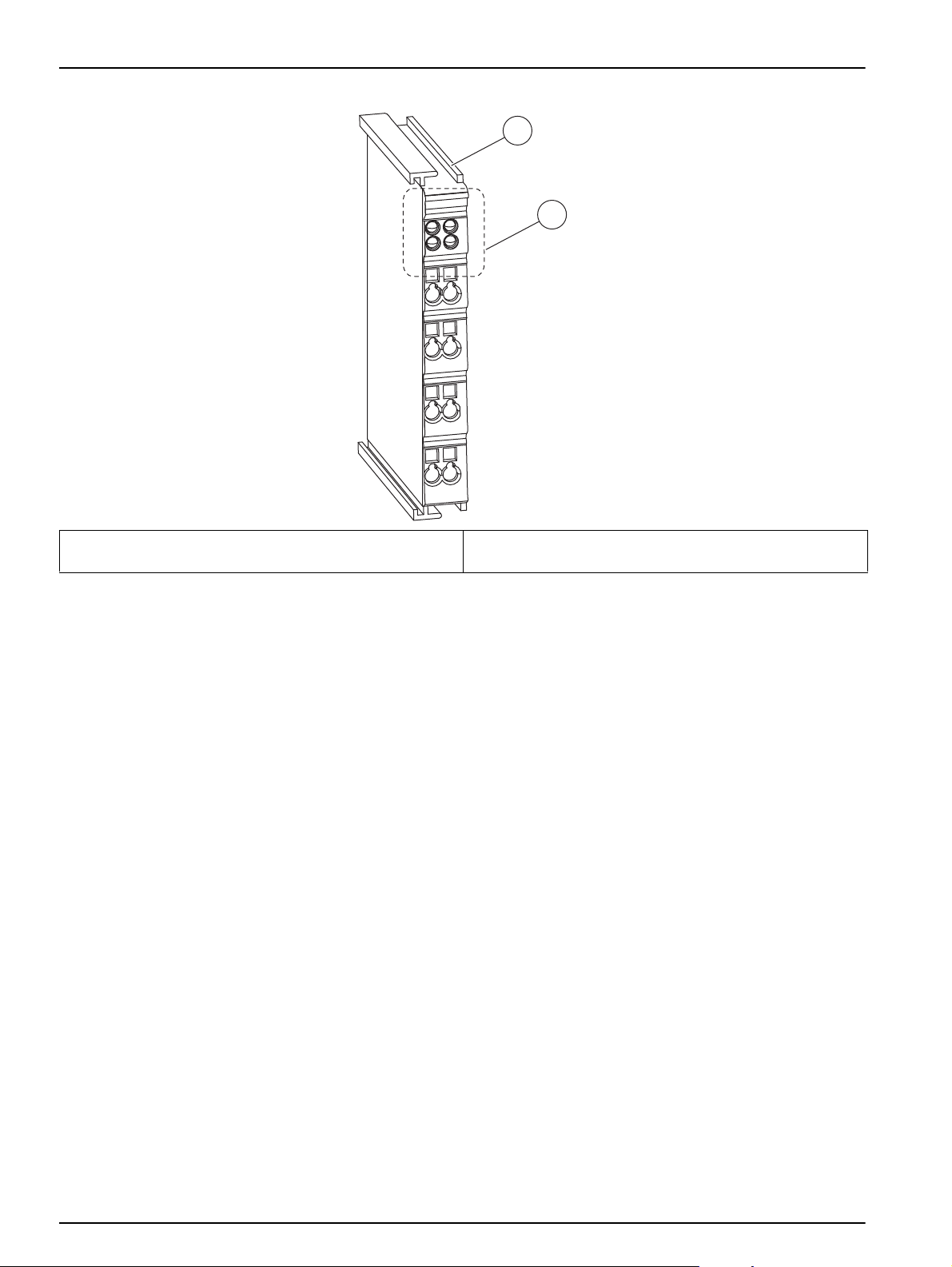
Figure 2 Design of the analog and digital input and output modules
1 Analog or digital input or output module
or bus termination module
Note: The number of LEDs indicates the number of channels.
2 LED area with installed LEDs or free LED installation
spaces.
2.5 Theory of operation
2.5.1 Theory of operation of the RTC103 N-Module
The RTC103 N-Module (Real-Time Controller for Nitrification) optimises nitrification
processes in waste water treatment plants which are continuously aerated (e.g. plug flow
nitrification tanks or pre-denitrification).
The RTC103 N-Module consists of an open-loop controller, based on NH
concentration, flow rate, and the temperature in the aeration tank. Optionally, the Total
Suspended Solids concentration in the aeration tank (MLSS) can be taken into account.
Based on that information, a DO set-point is calculated which is required to reach the
desired NH
control, there is also a closed-loop PID based on the NH
the nitrification zone that can be applied to improve control performance. The PID-output
values are combined with the open-loop output to calculate the required DO set point
(Figure 3).
-N set-point at the effluent of the aeration tank. In addition to open-loop
4
-N influent
4
-N concentration at the end of
4
12
Page 13
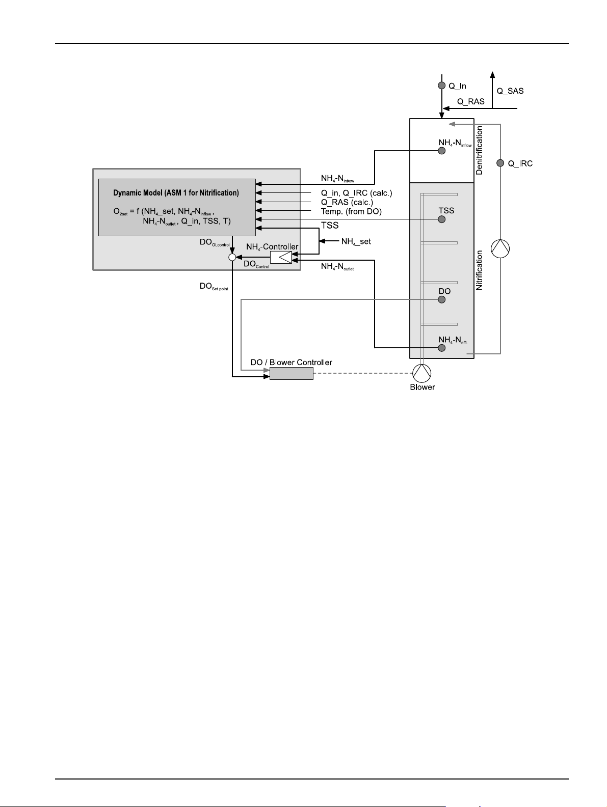
Figure 3 Principle operation mode of RTC103 N-Module
General Information
Basic RTC103 N-Module
For each lane the calculated DO set point is delivered either by analog output or via the
sc1000 ProfiBus communication card to the PLC. The DO control algorithm has to be
implemented on the PLC.
Option 2: RTC103 N-Module with DO aeration stages controller
The RTC103 N-Module is equipped with an additional DO controller adjusting the aeration
intensity to reach the calculated DO concentration. The DO control can have up to
6 different aeration stages per channel (e.g. in order to activate blower or activate discrete
aeration intensities). These aeration stages are activated by a min limit DO concentration
and the calculated DO set-point.
Option 3: RTC103 N-Module with analog DO controller
The RTC103 N-Module is equipped with an additional DO controller which, using
6 different aeration stages, adjusts the aeration intensity to reach the calculated DO
concentration. This option has two analog outputs per lane, to control up to two variable
speed drive blowers per lane.
All the above options for the RTC103 N-Module are available as single-channel (for
control of one lane) or dual-channel (for control of two lanes).
13
Page 14

General Information
14
Page 15
Section 3 Installation
Only qualified experts may perform the tasks described in this section of the manual, while
adhering to all locally valid safety regulations.
Always lay cables and hoses so that they are straight and do not pose a tripping hazard.
Before switching on the power supply, you must refer to the instructions in the relevant operating
manuals.
3.1 Installation of the RTC Module
Only install the RTC Module on a DIN rail. The module must be attached horizontally, with
at least 30 mm (1.2 in.) space at the top and bottom to make sure that the passive aeration
element can function correctly.
When used indoors, the RTC Module must be installed in a control cabinet.
When used outdoors, the RTC Module requires a suitable enclosure that supplies the
following technical specifications (see Section 1 Technical data, page 7).
DANGER
CAUTION
CAUTION
The RTC Module is only operated via the sc1000 controller (see the user manual for the
sc1000 controller).
Note: The software version of the sc1000 controller must be V3.20 or above.
3.1.1 Power supply to the RTC module
WARNING
Alternating current may destroy the direct current system and therefore jeopardize user safety.
Never connect an alternating current voltage to the 24 V direct current model.
Table 1 Supply voltage of the RTC Module
Voltage 24 V DC (–15 % / +20 %), max. 25 W
Recommended fuse C2
With 110–230 V option 230 V, 50–60 Hz, approximately 25 VA
Note: An external deactivation switch is recommended for all installations.
3.2 Connection of process measuring instruments (for NH4-N, TSS and
O
)
2
The measurement signals of the sc sensors for measuring NH4-N, TSS, Dissolved
Oxygen and Temperature (e.g. AMTAX sc, AN-ISE sc, AISE sc, SOLITAX sc, LDO2 sc,...)
are supplied to the RTC module via the RTC communication card (YAB117) in the sc1000.
3.2.1 Power supply of the sc sensors and the sc1000 controller
See operating instructions of the respective sc sensors and the sc1000 controller.
15
Page 16

Installation
3.3 Connecting the sc 1000 controller
The supplied SUB-D connector is attached to a two-wire, shielded data cable (signal or
bus cable). For additional information regarding the data cable connection, refer to the
enclosed assembly instructions.
3.4 Connection to the automation unit on the plant side
Depending on the variant (1-channel or 2-channel RTC103 N-Module, with or without DO
control) the RTC103 N-Module is equipped with various components that have to be
connected to the automation unit of the plant:
Output signals from RTC103 N-Module:
Basic For each lane, a single DO set-point 0/4 to 20 mA or ProfiBus / ModBus via
sc1000 communication card
Option 2 For each lane, Aeration intensity (1 to 6 stages) for the aeration system
(0/24 V per stage or ProfiBus / MODBUS) via sc1000 communication card
Option 3 For each lane, 2 additional analog outputs (0/4 to 20 mA or ProfiBus /
MODBUS) via sc1000 communication card
Input signals to RTC103 N-module:
• Flow rate, overall wastewater (Q_in, 0/4 to 20 mA)
• IRC flow rate input (Q_IRC, 0/4 to 20 mA)
or
IRC flow = C1 * Q_in with minimum and maximum values
• RAS flow rate (Q_RAS 0/4 to 20 mA)
or
RAS flow = C2 * Q_in with minimum and maximum values
Note: 0/4 to 20 mA input can be used either for Q_IRC or for Q_RAS. The other value has to be
calculated (C*Q_xxx with minimum and maximum values).
Input signals from sc1000 via RTC communication card to RTC103 N-module
• Common or individual NH4-N – concentration inlet aeration
(Measuring points: 1. Inflow 2. Settled Sewage and RAS Mixing / Distribution
Chamber 3. aeration tank after IRC input)
• Common or individual NH4-N – concentrations at the end of each lane
• DO concentration for each lane
• TSS concentration aeration tank (option)
• Temperature (coming from a connected sensor DO or NH
Main Input parameters:
, or via analog input card)
4
16
• Parameters for open-loop control
• Parameters for PID control (closed-loop)
• Min/max DO concentration, max. rate of change
• Control parameters for DO control
Page 17
Installation
1-Channel RTC103 N-Module
Module Name Terminal Signal Channel Function
2 fold digital output
1
KL2032
1 fold analog output KL4011 1 - 3 0/4 to 20 mA Output DO set point
1 fold analog intput KL3011 1 - 2 0/4 to 20 mA Flow rate aeration lane
1 fold analog input KL3011 1 - 2 0/4 to 20 mA Flow rate internal recirculation or return sludge
Bus termination KL9010 Bus termination
1
Ground Connector 3 and 7, 24 V Connector 6.
2-Channel RTC103 N-Module
Module Name Terminal Signal Channel Function
4 fold digital output1KL2134
2 fold analog output KL4012
1 fold analog intput KL3011 1 - 2 0/4 to 20 mA 1 Flow rate aeration lane 1
1 fold analog input KL3011 1 - 2 0/4 to 20 mA 2
1 fold analog intput KL3011 1 - 2 0/4 to 20 mA 1 Flow rate aeration lane 2
1 fold analog input KL3011 1 - 2 0/4 to 20 mA 2
Bus termination KL9010 Bus termination
1 +24 V/0 V Input Signals ok (24V), Input signal faulty (0V)
5 +24 V/0 V RTC operating (24V), RTC failure (0V)
1 +24 V/0 V 1 Input Signals ok (24V), Input signal faulty (0V)
5 +24 V/0 V 1 RTC operating (24V), RTC failure (0V)
4 +24 V/0 V 2 Input Signals ok (24V), Input signal faulty (0V)
8 +24 V/0 V 2 RTC operating (24V), RTC failure (0V)
1 - 3 0/4 to 20 mA 1 Output DO set point lane 1
5 - 7 0/4 to 20 mA 2 Output DO set point lane 2
Flow rate internal recirculation or return sludge
lane 1
Flow rate internal recirculation or return sludge
lane 2
1
Ground Connector 3 and 7, 24 V Connector 6.
1-Channel RTC103 N-Module DO aeration stages control
Module Name Terminal Signal Channel Function
1 +24 V/0 V Input Signals ok (24V), Input signal faulty (0V)
2 +24 V/0 V Aeration step 1 ON / OFF
3 +24 V/0 V Aeration step 2 ON / OFF
8 fold digital output
1
KL2408
4 +24 V/0 V Aeration step 3 ON / OFF
5 +24 V/0 V Aeration step 4 ON / OFF
6 +24 V/0 V Aeration step 5 ON / OFF
7 +24 V/0 V Aeration step 6 ON / OFF
8 +24 V/0 V RTC operating (24V), RTC failure (0V)
1 fold analog output KL4011 1 - 3 0/4 to 20 mA Output DO set point
1 fold analog intput KL3011 1 - 2 0/4 to 20 mA Flow rate aeration lane
1 fold analog input KL3011 1 - 2 0/4 to 20 mA Flow rate internal recirculation or return sludge
Bus termination KL9010 Bus termination
1
Ground Connector 3 and 7, 24 V Connector 6.
17
Page 18

Installation
2-Channel RTC103 N-Module DO aeration stages control
Module Name Terminal Signal Channel Function
1 +24 V/0 V 1 Input Signals ok (24V), Input signal faulty (0V)
2 +24 V/0 V 1 Aeration step 1 ON / OFF
3 +24 V/0 V 1 Aeration step 2 ON / OFF
4 +24 V/0 V 1 Aeration step 3 ON / OFF
5 +24 V/0 V 1 Aeration step 4 ON / OFF
6 +24 V/0 V 1 Aeration step 5 ON / OFF
7 +24 V/0 V Aeration step 6 ON / OFF
16 fold digital output1KL2809
2 fold analog output KL4012
1 fold analog intput KL3011 1 - 2 0/4 to 20 mA 1 Flow rate aeration lane 1
1 fold analog input KL3011 1 - 2 0/4 to 20 mA 2
1 fold analog intput KL3011 1 - 2 0/4 to 20 mA 1 Flow rate aeration lane 2
1 fold analog input KL3011 1 - 2 0/4 to 20 mA 2
Bus termination KL9010 Bus termination
8 +24 V/0 V RTC Channel 1 operating (24V), RTC failure (0V)
9 +24 V/0 V 2 Input Signals ok (24V), Input signal faulty (0V)
10 +24 V/0 V 2 Aeration step 1 ON / OFF
11 +24 V/0 V 2 Aeration step 2 ON / OFF
12 +24 V/0 V 2 Aeration step 3 ON / OFF
13 +24 V/0 V 2 Aeration step 4 ON / OFF
14 +24 V/0 V 2 Aeration step 5 ON / OFF
15 +24 V/0 V Aeration step 6 ON / OFF
16 +24 V/0 V RTC Channel 2 operating (24V), RTC failure (0V)
1 - 3 0/4 to 20 mA 1 Output DO set point lane 1
5 - 7 0/4 to 20 mA 2 Output DO set point lane 2
Flow rate internal recirculation or return sludge
lane 1
Flow rate internal recirculation or return sludge
lane 2
1
Ground Connector 3 and 7, 24 V Connector 6.
1-Channel RTC103 N-Module connectors DO aeration stages / analog control
Module Name Terminal Signal Channel Function
1 +24 V/0 V Input Signals ok (24V), Input signal faulty (0V)
2 +24 V/0 V Aeration step 1 ON / OFF (VFD)
3 +24 V/0 V Aeration step 2 ON / OFF (VFD)
8 fold digital output
1
KL2408
4 +24 V/0 V Aeration step 3 ON / OFF
5 +24 V/0 V Aeration step 4 ON / OFF
6 +24 V/0 V Aeration step 5 ON / OFF
7 +24 V/0 V Aeration step 6 ON / OFF
8 +24 V/0 V RTC operating (24V), RTC failure (0V)
2 fold analog output KL4012
1 - 3 0/4 to 20 mA Output 1 VFD for DO control
5 - 7 0/4 to 20 mA Output 2 VFD for DO control
1 fold analog intput KL3011 1 - 2 0/4 to 20 mA Flow rate aeration lane
1 fold analog input KL3011 1 - 2 0/4 to 20 mA Flow rate internal recirculation
Bus termination KL9010 Bus termination
1
Ground Connector 3 and 7, 24 V Connector 6.
18
Page 19

2-Channel RTC103 N-Module connectors DO aeration stages / analog control
Module Name Terminal Signal Channel Function
1 +24 V/0 V 1 Input Signals ok (24V), Input signal faulty (0V)
2 +24 V/0 V 1 Aeration step 1 ON / OFF (VFD)
3 +24 V/0 V 1 Aeration step 2 ON / OFF (VFD)
4 +24 V/0 V 1 Aeration step 3 ON / OFF
5 +24 V/0 V 1 Aeration step 4 ON / OFF
6 +24 V/0 V 1 Aeration step 5 ON / OFF
7 +24 V/0 V 1 Aeration step 6 ON / OFF
16 fold digital output1KL2809
2 fold analog output KL4012
2 fold analog output KL4012
1 fold analog intput KL3011 1 - 2 0/4 to 20 mA 1 Flow rate aeration lane
1 fold analog input KL3011 1 - 2 0/4 to 20 mA 1 Flow rate internal recirculation
1 fold analog intput KL3011 1 - 2 0/4 to 20 mA 2 Flow rate aeration lane
1 fold analog input KL3011 1 - 2 0/4 to 20 mA 2 Flow rate internal recirculation
Bus termination KL9010 Bus termination
8 +24 V/0 V 1 RTC Channel 1 operating (24V), RTC failure (0V)
9 +24 V/0 V 2 Input Signals ok (24V), Input signal faulty (0V)
10 +24 V/0 V 2 Aeration step 1 ON / OFF (VFD)
11 +24 V/0 V 2 Aeration step 2 ON / OFF (VFD)
12 +24 V/0 V 2 Aeration step 3 ON / OFF
13 +24 V/0 V 2 Aeration step 4 ON / OFF
14 +24 V/0 V 2 Aeration step 5 ON / OFF
15 +24 V/0 V 2 Aeration step 6 ON / OFF
16 +24 V/0 V 2 RTC Channel 2 operating (24V), RTC failure (0V)
0/4 to 20 mA 1 Output 1 VFD for DO control
0/4 to 20 mA 1 Output 2 VFD for DO control
0/4 to 20 mA 2 Output 1 VFD for DO control
0/4 to 20 mA 2 Output 2 VFD for DO control
Installation
1
Ground Connector 3 and 7, 24 V Connector 6.
19
Page 20

Installation
20
Page 21

Section 4 Parameterization and operation
4.1 Operating the sc controller
The RTC module can only be operated using the sc1000
controller, in conjunction with the RTC communication card.
Before the RTC module is used, the user must be familiar with
the functionality of the sc1000 controller. Learn how to navigate
through the menu and perform the relevant functions.
4.2 System setup
1. Open the MAIN MENU.
4.3 Menu structure
4.3.1 SENSOR STATUS
SENSOR STATUS
RTC
ERROR
WARNINGS
4.3.2 SYSTEM SETUP
2. Select
3. Select the
4. Select the RTC module and confirm.
Possible error messages:
RTC MISSING, RTC CRC, CHECK KONFIG, RTC FAILURE
Possible warning messages:
MODBUS ADDRESS, PROBE SERVICE
Note: Refer to Section 6 Troubleshooting, page 55 for a list of all
possible error and warning messages together with a description of all
necessary countermeasures to be taken.
The system setup is dependent on the number of channels.
RTC MODULES / PROGNOSYS and confirm.
RTC MODULES menu and confirm.
For 1-channel:
refer to 4.4 1-Channel RTC103 N-Module parameterization on
sc1000 controller, page 21.
For 2-channel:
refer to 4.5 2-channel RTC103 N-Module parameterization on the
sc1000 controller, page 32
4.4 1-Channel RTC103 N-Module parameterization on sc1000 controller
The following menu entries can be found in the MAIN MENU.
21
Page 22

Parameterization and operation
4.4.1 1-Channel RTC103 N-Module
RTC MODULES / PROGNOSYS
RTC MODULES
RTC
CONFIGURE
SELECT SENSOR
N CONTROL
SRT MODE
SRT (MANUALLY) Manual input for the SRT (also used as fallback value) [days]
DAILY SURPLUS MASS
COD-TKN RATIO
MIN NITRIFERS CONC.
MAX NITRIFERS CONC.
MODEL CORRECTION FACT.
SUBSTIT. DO FOR MODEL
NH4-N SETPOINT Desired set point of the NH4-N concentration effluent aeration. [mg/L]
Selection list of available, relevant sensors for the RTC module in
the sc network (refer to 4.6 Select sensors on page 45).
Three different types of operation regarding the aerobic Sludge
Retention Time (SRT) can be selected:
•Manually: The SRT is provided as a manual input to the
controller
•SRT-RTC: The SRT is provided by a separate SRT-RTC and
forwarded to the RTC103 N-Module
• TSS mL: The SRT is calculated based on the TSS
concentration and the amount of TSS daily removed.
The amount of sludge daily removed from the process. Based on
that amount, the MLSS concentration in the aeration tank and the
aerated volume the SRT is calculated.
This is the assumed COD / TKN ratio. The N-RTC considers a
certain COD-related amount of NH4-N to be incorporated in the bio
mass, reducing the amount of NH4-N to be nitrified.
Based on the amount of NH4-N nitrified during the last SRT, the
N-RTC calculates the concentration of nitrifiers in the activated
sludge. This concentration is required to determine the DO set point.
If the calculated concentration is lower than the MIN NITRIFERS
CONC., the MIN NITRIFERS CONC. will be used to determine the
DO set point.
Based on the amount of NH4-N nitrified during the last SRT, the
N-RTC calculates the concentration of nitrifiers in the activated
sludge. This concentration is required to determine the DO set point.
If the calculated concentration is higher than the MAX NITRIFERS
CONC., the MAX NITRIFERS CONC.. will be used to determine the
DO set point.
This factor can be used to fine tune the DO concentration calculated
by the model (feed forward part of the N-RTC).
If there is a failure in any of the input signals (NH4-N, TSS, Flow) the
N-RTC will apply this DO feed forward set point for all further
calculations.
[kg/d]
[%]
]%]
[mg/L]
22
Page 23

4.4.1 1-Channel RTC103 N-Module (Continued)
RTC MODULES / PROGNOSYS
RTC MODULES
RTC
Note: These settings are only necessary if NH
effluent for feed back control is available!
P FACT NH4
Proportional factor for the PID closed loop controller for the NH4-N
concentration effluent aeration.
Note: These settings are only necessary if NH
effluent for feed back control is available!
Parameterization and operation
-N measurement in
4
[1/mg/L]
-N measurement in
4
INTEGRAL TIME NH4
DERIVATIVE TIME NH4
LIMITS
MIN DO
MAX DO
SMOOTHING Smoothing on the calculated DO set point [min]
INPUTS
MIN INFLOW
MAX INFLOW
0/4 to 20 mA
Integral time for the PID closed loop controller for the NH4-N
concentration in the thickened sludge.
Note: INTEGRAL TIME NH4 is set to “0” to deactivate the integral
part of the PID controller.
Note: These settings are only necessary if NH
effluent for feed back control is available!
Derivation time for the PID closed loop controller for the NH4-N
concentration effluent aeration
Note: DERIVATIVE TIME NH4 is set to “0” to deactivate the
derivative part of the PID controller.
If a calculated DO set point is lower than the MIN DO value, the DO
set point is set to that value
If a calculated DO set point is higher than the MIN DO value, the DO
set point is set to that value
Minimum flow rate of influent according to measurement signal
corresponding to 0/4mA
Maximum flow rate of influent according to measurement signal
corresponding to 20mA
Transfer range of 0/4 to 20 mA current loop as set in connected flow
measuring instrument.
-N measurement in
4
[min]
[min]
[mg/L]
[mg/L]
[L/s]
[L/s]
23
Page 24

Parameterization and operation
4.4.1 1-Channel RTC103 N-Module (Continued)
RTC MODULES / PROGNOSYS
RTC MODULES
RTC
Note: 0/4 to20 mA input can be used either for Qreci or for Qras.
MIN RECIRCULATION
MAX RECIRCULATION
0/4 to 20 mA
Q RECI RATIO
MIN RETURN SLUDGE
Minimum recirculation flow rate according to measurement signal
corresponding to 0/4mA
Note: 0/4 to20 mA input can be used either for Qreci or for Qras.
Maximum recirculation flow rate of influent according to
measurement signal corresponding to 20mA
Note: 0/4 to20 mA input can be used either for Qreci or for Qras.
Transfer range of 0/4 to 20 mA current loop as set in connected flow
measuring instrument.
Note: The input is not connected to the 0/4 to 20 mA has to be
calculated in ratio to Qinflow.
Note: 0/4 to20 mA input can be used either for Qreci or for Qras.
If the value Q RECI RATIO is “0” the RECI flow is calculated bases
on the mA input signal.
If the value is different from “0” the RECI flow is calculated from the
inflow:
Q RECI= Q RECI RATIO * INFLOW
within the limits of MIN RECIRCULATION and MAX
RECIRCULATION.
Note: 0/4 to20 mA input can be used either for Qreci or for Qras.
Minimum return sludge flow rate according to measurement signal
corresponding to 0/4mA
Note: 0/4 to20 mA input can be used either for Qreci or for Qras.
[L/s]
[L/s]
[%]
[L/s]
24
MAX RETURN SLUDGE
0/4 to 20 mA
Q RETURN RATIO
Maximum return sludge flow rate of influent according to
measurement signal corresponding to 20mA
Note: 0/4 to20 mA input can be used either for Qreci or for Qras.
Transfer range of 0/4 to 20 mA current loop as set in connected flow
measuring instrument.
Note: 0/4 to20 mA input can be used either for Qreci or for Qras.
If the value Q RETURN RATIO is “0” the RAS flow is calculated
bases on the mA input signal.
If the value is different from “0” the RAS flow is calculated from the
inflow:
Q RETURN = Q RETURN RATIO * INFLOW
within the limits of MIN RETURN SLUDGE and MAX RETURN
SLUDGE.
[L/s]
[%]
Page 25

Parameterization and operation
4.4.1 1-Channel RTC103 N-Module (Continued)
RTC MODULES / PROGNOSYS
RTC MODULES
RTC
OUTPUTS
MIN DO SETTING Minimum DO set point corresponding to 0/4mA [mg/L]
MAX DO SETTING Maximum DO set point corresponding to 20mA [mg/L]
0/4 to 20 mA
VOLUME
VOLUME Aerated volume [m
MODBUS
ADDRESS Start address of an RTC within the MODBUS network.
DATA ORDER
DATALOG INTRVAL Indicates the interval in which the data is saved in the log file. [min]
PROGNOSYS
SET DEFAULTS Restores the factory settings.
MAINTENANCE
RTC DATA
RTC MEASUREMEN
RTC ACTUAT VAR
DIAG/TEST
EEPROM Hardware test
RTC COMM TO Communication time-out
RTC CRC Communication check sum
MODBUS ADDRESS
LOCATION
SOFT-VERSION
RTC MODE
RTC VERSION Shows the software version of the RTC module.
Transfer range of 0/4 to 20 mA current loop as set in connected flow
measuring instrument.
Specifies the register order within a double word. Presetting:
NORMAL
Activate or deactivate PROGNOSYS for RTC control. "Activate"
means if Measurement Indicator from relevant sensor decrease to
50% or lower RTC control do not use this measurement and switch
to adequate fall back strategy.
Specifies the value measured by the RTC, e. g. the influent
measurement.
Specifies the variable calculated by the RTC, e. g. whether the
aeration should be switched on or off.
Here, the address is displayed where the communication actually
takes place. Presetting: 41
Here, a location name can be assigned for better identification of the
RTC module, e.g. activation 2.
Shows the software version of the RTC communication card
(YAB117) in the sc1000.
Shows the installed RTC module variant, e.g. 1-channel closed-loop
control.
3
]
25
Page 26

Parameterization and operation
4.4.2 1-Channel RTC103 N-Module Stages
RTC MODULES / PROGNOSYS
RTC MODULES
RTC
CONFIGURE
SELECT SENSOR
N CONTROL
SRT MODE
SRT (MANUALLY) Manual input for the SRT (also used as fallback value) [days]
DAILY SURPLUS MASS
COD-TKN RATIO
MIN NITRIFERS CONC.
MAX NITRIFERS CONC.
Selection list of available, relevant sensors for the RTC module in
the sc network (refer to 4.6 Select sensors on page 45).
Three different types of operation regarding the aerobic Sludge
Retention Time (SRT) can be selected:
•Manually: The SRT is provided as a manual input to the
controller
•SRT-RTC: The SRT is provided by a separate SRT-RTC and
forwarded to the RTC103 N-Module
•TSS mL: The SRT is calculated based on the TSS
concentration and the amount of TSS daily removed.
The amount of sludge daily removed from the process. Based on
that amount, the MLSS concentration in the aeration tank and the
aerated volume the SRT is calculated.
This is the assumed COD / TKN ratio. The N-RTC considers a
certain COD-related amount of NH4-N to be incorporated in the bio
mass, reducing the amount of NH4-N to be nitrified.
Based on the amount of NH4-N nitrified during the last SRT, the
N-RTC calculates the concentration of nitrifiers in the activated
sludge. This concentration is required to determine the DO set point.
If the calculated concentration is lower than the MIN NITRIFERS
CONC., the MIN NITRIFERS CONC. will be used to determine the
DO set point.
Based on the amount of NH4-N nitrified during the last SRT, the
N-RTC calculates the concentration of nitrifiers in the activated
sludge. This concentration is required to determine the DO set point.
If the calculated concentration is higher than the MAX NITRIFERS
CONC., the MAX NITRIFERS CONC.. will be used to determine the
DO set point.
[kg/d]
[%]
]%]
26
Page 27

4.4.2 1-Channel RTC103 N-Module Stages (Continued)
RTC MODULES / PROGNOSYS
RTC MODULES
RTC
MODEL CORRECTION FACT.
SUBSTIT. DO FOR MODEL
NH4-N SETPOINT
P FACT NH4
INTEGRAL TIME NH4
DERIVATIVE TIME NH4
LIMITS
MIN DO
MAX DO
SMOOTHING Smoothing on the calculated DO set point [min]
DO CONTROL
DERIVATIVE TIME Derivative Time of DO controller [min]
DAMPING Damping of DO control [min]
SUBST AERATION
NO. OF STAGES Number of controlled aeration stages (maximun 6) [Stage]
VFD P MIN fixed to 100% [%]
INPUTS
MIN INFLOW
MAX INFLOW
0/4 to 20 mA
This factor can be used on order to fine tune the DO concentration
calculated by the model (feed forward part of the N-RTC).
If there is a failure in any of the input signals (NH4-N, TSS, Flow) the
N-RTC will apply the this DO feed forward set point for all further
calculation
Desired set point of the NH4-N concentration effluent aeration
Note: These settings are only necessary if NH4-N measurement in
effluent for feed back control is available!
Proportional factor for the PID closed loop controller for the NH4-N
concentration effluent aeration.
Integral time for the PID closed loop controller for the NH4-N
concentration in the thickened sludge.
Note: INTEGRAL TIME NH4 is set to “0” to deactivate the integral
part of the PID controller.
Derivation time for the PID closed loop controller for the NH4-N
concentration effluent aeration
Note: DERIVATIVE TIME NH4 is set to “0” to deactivate the
derivative part of the PID controller.
If a calculated DO set point is lower than the MIN DO value, the DO
set point is set to that value
If a calculated DO set point is higher than the MIN DO value, the DO
set point is set to that value
If the DO sensor (e.g. LDO) signals a fault, the set aeration stage is
selected
Minimum flow rate of influent according to measurement signal
corresponding to 0/4mA
Maximum flow rate of influent according to measurement signal
corresponding to 20mA
Transfer range of 0/4 to 20 mA current loop as set in connected flow
measuring instrument.
Note: 0/4 to 20 mA input can be used either for Qreci or for Qras!
Parameterization and operation
[mg/L]
[mg/L]
[1/mg/L]
[min]
[min]
[mg/L]
[mg/L]
[Stage]
[L/s]
[L/s]
27
Page 28

Parameterization and operation
4.4.2 1-Channel RTC103 N-Module Stages (Continued)
RTC MODULES / PROGNOSYS
RTC MODULES
RTC
Note: 0/4 to20 mA input can be used either for Qreci or for Qras.
MIN RECIRCULATION
MAX RECIRCULATION
0/4 to 20 mA
Q RECI RATIO
MIN RETURN SLUDGE
Minimum recirculation flow rate according to measurement signal
corresponding to 0/4mA
Note: 0/4 to20 mA input can be used either for Qreci or for Qras.
Maximum recirculation flow rate of influent according to
measurement signal corresponding to 20mA
Note: 0/4 to20 mA input can be used either for Qreci or for Qras.
Transfer range of 0/4 to 20 mA current loop as set in connected flow
measuring instrument.
Note: The input is not connected to the 0/4 to 20 mA has to be
calculated in ratio to Qinflow.
Note: 0/4 to20 mA input can be used either for Qreci or for Qras.
If the value Q RECI RATIO is “0” the RECI flow is calculated bases
on the mA input signal.
If the value is different from “0” the RECI flow is calculated from the
inflow:
Q RECI= Q RECI RATIO * INFLOW
within the limits of MIN RECIRCULATION and MAX
RECIRCULATION.
Note: 0/4 to20 mA input can be used either for Qreci or for Qras.
Minimum return sludge flow rate according to measurement signal
corresponding to 0/4mA
Note: 0/4 to20 mA input can be used either for Qreci or for Qras.
[L/s]
[L/s]
[%]
[L/s]
28
MAX RETURN SLUDGE
0/4 to 20 mA
Q RETURN RATIO
VOLUME
VOLUME Aerated volume [m
Maximum return sludge flow rate of influent according to
measurement signal corresponding to 20mA
Note: 0/4 to20 mA input can be used either for Qreci or for Qras.
Transfer range of 0/4 to 20 mA current loop as set in connected flow
measuring instrument.
Note: 0/4 to20 mA input can be used either for Qreci or for Qras.
If the value Q RETURN RATIO is “0” the RAS flow is calculated
bases on the mA input signal.
If the value is different from “0” the RAS flow is calculated from the
inflow:
Q RETURN = Q RETURN RATIO * INFLOW
within the limits of MIN RETURN SLUDGE and MAX RETURN
SLUDGE.
[L/s]
[%]
3
]
Page 29

4.4.3 1-Channel RTC103 N-Module VFD
RTC MODULES / PROGNOSYS
RTC MODULES
RTC
CONFIGURE
SELECT SENSOR
N CONTROL
SRT MODE
SRT (MANUALLY) Manual input for the SRT (also used as fallback value) [days]
DAILY SURPLUS MASS
COD-TKN RATIO
MIN NITRIFERS CONC.
MAX NITRIFERS CONC.
MODEL CORRECTION FACT.
SUBSTIT. DO FOR MODEL
NH4-N SETPOINT Desired set point of the NH4-N concentration effluent aeration [mg/L]
Selection list of available, relevant sensors for the RTC module in
the sc network (refer to 4.6 Select sensors on page 45).
Three different types of operation regarding the aerobic Sludge
Retention Time (SRT) can be selected:
•Manually: The SRT is provided as a manual input to the
controller
•SRT-RTC: The SRT is provided by a separate SRT-RTC and
forwarded to the RTC103 N-Module
•TSS mL: The SRT is calculated based on the TSS
concentration and the amount of TSS daily removed.
The amount of sludge daily removed from the process. Based on
that amount, the MLSS concentration in the aeration tank and the
aerated volume the SRT is calculated.
This is the assumed COD / TKN ratio. The N-RTC considers a
certain COD-related amount of NH4-N to be incorporated in the bio
mass, reducing the amount of NH4-N to be nitrified.
Based on the amount of NH4-N nitrified during the last SRT, the
N-RTC calculates the concentration of nitrifiers in the activated
sludge. This concentration is required to determine the DO set point.
If the calculated concentration is lower than the MIN NITRIFERS
CONC., the MIN NITRIFERS CONC. will be used to determine the
DO set point.
Based on the amount of NH4-N nitrified during the last SRT, the
N-RTC calculates the concentration of nitrifiers in the activated
sludge. This concentration is required to determine the DO set point.
If the calculated concentration is higher than the MAX NITRIFERS
CONC., the MAX NITRIFERS CONC.. will be used to determine the
DO set point.
This factor can be used on order to fine tune the DO concentration
calculated by the model (feed forward part of the N-RTC).
If there is a failure in any of the input signals (NH4-N, TSS, Flow) the
N-RTC will apply the this DO feed forward set point for all further
calculation
Parameterization and operation
[kg/d]
[%]
]%]
[mg/L]
29
Page 30

Parameterization and operation
4.4.3 1-Channel RTC103 N-Module VFD (Continued)
RTC MODULES / PROGNOSYS
RTC MODULES
RTC
Note: These settings are only neces sary if NH
effluent for feed back control is available!
P FACT NH4
Proportional factor for the PID closed loop controller for the NH4-N
concentration effluent aeration.
Note: These settings are only neces sary if NH
effluent for feed back control is available!
-N measurement in
4
-N measurement in
4
[1/mg/L]
INTEGRAL TIME NH4
DERIVATIVE TIME NH4
LIMITS
MIN DO
MAX DO
SMOOTHING Smoothing on the calculated DO set point [min]
DO CONTROLL
P GAIN DO
DERIVATIVE TIME Derivative Time of DO controller [min]
INT PART Integral part for DO control
DAMPING Damping of DO control [min]
SUBST AERATION
NO. OF STAGES Number of controlled aeration stages (maximun 6) [Stage]
VFD P MIN Set minimum speed for VFD controlled blowers (stage 1 and 2) [%]
INPUTS
MIN INFLOW
MAX INFLOW
0/4 to 20 mA
Integral time for the PID closed loop controller for the NH4-N
concentration in the thickened sludge.
Note: INTEGRAL TIME NH4 is set to “0” to deactivate the integral
part of the PID controller.
Note: These settings are only neces sary if NH
effluent for feed back control is available!
Derivation time for the PID closed loop controller for the NH4-N
concentration effluent aeration
Note: DERIVATIVE TIME NH4 is set to “0” to deactivate the
derivative part of the PID controller.
If a calculated DO set point is lower than the MIN DO value, the DO
set point is set to that value
If a calculated DO set point is higher than the MIN DO value, the DO
set point is set to that value
Proportional factor for the PD closed loop controller for the DO
concentrtion in the aeration.
If the DO sensor (e.g. LDO) signals a fault, the set aeration stage is
selected
Minimum flow rate of influent according to measurement signal
corresponding to 0/4mA
Maximum flow rate of influent according to measurement signal
corresponding to 20mA
Transfer range of 0/4 to 20 mA current loop as set in connected flow
measuring instrument.
-N measurement in
4
[min]
[min]
[mg/L]
[mg/L]
[1/mg/L]
[Stage]
[L/s]
[L/s]
30
Page 31

4.4.3 1-Channel RTC103 N-Module VFD (Continued)
RTC MODULES / PROGNOSYS
RTC MODULES
RTC
Note: 0/4 to20 mA input can be used either for Qreci or for Qras.
Parameterization and operation
MIN RECIRCULATION
MAX RECIRCULATION
0/4 to 20 mA
Q RECI RATIO
MIN RETURN SLUDGE
Minimum recirculation flow rate according to measurement signal
corresponding to 0/4mA
Note: 0/4 to20 mA input can be used either for Qreci or for Qras.
Maximum recirculation flow rate of influent according to
measurement signal corresponding to 20mA
Note: 0/4 to20 mA input can be used either for Qreci or for Qras.
Transfer range of 0/4 to 20 mA current loop as set in connected flow
measuring instrument.
Note: The input is not connected to the 0/4 to 20 mA has to be
calculated in ratio to Qinflow.
Note: 0/4 to20 mA input can be used either for Qreci or for Qras.
If the value Q RECI RATIO is “0” the RECI flow is calculated bases
on the mA input signal.
If the value is different from “0” the RECI flow is calculated from the
inflow:
Q RECI= Q RECI RATIO * INFLOW
within the limits of MIN RECIRCULATION and MAX
RECIRCULATION.
Note: 0/4 to20 mA input can be used either for Qreci or for Qras.
Minimum return sludge flow rate according to measurement signal
corresponding to 0/4mA
Note: 0/4 to20 mA input can be used either for Qreci or for Qras.
[L/s]
[L/s]
[%]
[L/s]
MAX RETURN SLUDGE
0/4 to 20 mA
Q RETURN RATIO
OUTPUTS
0/4 to 20 mA
VOLUME
VOLUME Aerated volume [m
Maximum return sludge flow rate of influent according to
measurement signal corresponding to 20mA
Note: 0/4 to20 mA input can be used either for Qreci or for Qras.
Transfer range of 0/4 to 20 mA current loop as set in connected flow
measuring instrument.
Note: 0/4 to20 mA input can be used either for Qreci or for Qras.
If the value Q RETURN RATIO is “0” the RAS flow is calculated
bases on the mA input signal.
If the value is different from “0” the RAS flow is calculated from the
inflow:
Q RETURN = Q RETURN RATIO * INFLOW
within the limits of MIN RETURN SLUDGE and MAX RETURN
SLUDGE.
Analog outputs to control VFD blowers.
Transfer range of 0/4 to 20 mA current loop
[L/s]
[%]
3
]
31
Page 32

Parameterization and operation
4.4.3 1-Channel RTC103 N-Module VFD (Continued)
RTC MODULES / PROGNOSYS
RTC MODULES
RTC
MODBUS
ADDRESS Start address of an RTC within the MODBUS network.
DATA ORDER
DATALOG INTRVAL Indicates the interval in which the data is saved in the log file. [min]
PROGNOSYS
SET DEFAULTS Restores the factory settings.
MAINTENANCE
RTC DATA
RTC MEASUREMEN
RT C A CT U AT VAR
DIAG/TEST
EEPROM Hardware test
RTC COMM TO Communication time-out
RTC CRC Communication check sum
MODBUS ADDRESS
LOCATION
SOFT-VERSION
RTC MODE
RTC VERSION Shows the software version of the RTC module.
Specifies the register order within a double word. Presetting:
NORMAL
Activate or deactivate PROGNOSYS for RTC control. "Activate"
means if Measurement Indicator from relevant sensor decrease to
50% or lower RTC control do not use this measurement and switch
to adequate fall back strategy.
Specifies the value measured by the RTC, e. g. the influent
measurement.
Specifies the variable calculated by the RTC, e. g. whether the
aeration should be switched on or off.
Here, the address is displayed where the communication actually
takes place. Presetting: 41
Here, a location name can be assigned for better identification of the
RTC module, e.g. activation 2.
Shows the software version of the RTC communication card
(YAB117) in the sc1000.
Shows the installed RTC module variant, e.g. 1-channel closed-loop
control.
4.5 2-channel RTC103 N-Module parameterization on the sc1000 controller
In addition to the 1-channel version, there is also a 2-channel
version that can control two activated sludge tanks. The relevant
parameters therefore appear twice and are identified as channel
1 and channel 2.
32
Page 33

4.5.1 2-Channel RTC103 N-Module
RTC MODULES / PROGNOSYS
RTC MODULES
RTC
CONFIGURE
SELECT SENSOR
N CONTROL
SRT MODE
SRT (MANUALLY) Manual input for the SRT (also used as fallback value) [days]
DAILY SURPLUS MASS
COD-TKN RATIO
MIN NITRIFERS CONC.
MAX NITRIFERS CONC.
Selection list of available, relevant sensors for the RTC module in
the sc network (refer to 4.6 Select sensors on page 45).
Three different types of operation regarding the aerobic Sludge
Retention Time (SRT) can be selected:
•Manually: The SRT is provided as a manual input to the
controller
•SRT-RTC: The SRT is provided by a separate SRT-RTC and
forwarded to the RTC103 N-Module
•TSS mL: The SRT is calculated based on the TSS
concentration and the amount of TSS daily removed.
The amount of sludge daily removed from the process. Based on
that amount, the MLSS concentration in the aeration tank and the
aerated volume the SRT is calculated.
This is the assumed COD / TKN ratio. The N-RTC considers a
certain COD-related amount of NH4-N to be incorporated in the bio
mass, reducing the amount of NH4-N to be nitrified.
Based on the amount of NH4-N nitrified during the last SRT, the
N-RTC calculates the concentration of nitrifiers in the activated
sludge. This concentration is required to determine the DO set point.
If the calculated concentration is lower than the MIN NITRIFERS
CONC., the MIN NITRIFERS CONC. will be used to determine the
DO set point.
Based on the amount of NH4-N nitrified during the last SRT, the
N-RTC calculates the concentration of nitrifiers in the activated
sludge. This concentration is required to determine the DO set point.
If the calculated concentration is higher than the MAX NITRIFERS
CONC., the MAX NITRIFERS CONC.. will be used to determine the
DO set point.
Parameterization and operation
[kg/d]
[%]
]%]
33
Page 34

Parameterization and operation
4.5.1 2-Channel RTC103 N-Module (Continued)
RTC MODULES / PROGNOSYS
RTC MODULES
RTC
MODEL CORRECTION FACT.
SUBSTIT. DO FOR MODEL
NH4-N SETPOINT Desired set point of the NH4-N concentration effluent aeration [mg/L]
P FACT NH4
This factor can be used to fine tune the DO concentration calculated
by the model (feed forward part of the N-RTC).
If there is a failure in any of the input signals (NH4-N, TSS, Flow) the
N-RTC will apply this DO feed forward set point for all further
calculations.
Note: These settings are only neces sary if NH
effluent for feed back control is available!
Proportional factor for the PID closed loop controller for the NH4-N
concentration effluent aeration.
Note: These settings are only neces sary if NH
effluent for feed back control is available!
-N measurement in
4
-N measurement in
4
[mg/L]
[1/mg/L]
INTEGRAL TIME NH4
DERIVATIVE TIME NH4
LIMITS
MIN DO
MAX DO
SMOOTHING Smoothing on the calculated DO set point [min]
INPUTS
CHANNEL 1
MIN INFLOW
MAX INFLOW
0/4 to 20 mA
Integral time for the PID closed loop controller for the NH4-N
concentration in the thickened sludge.
Note: INTEGRAL TIME NH4 is set to “0” to deactivate the integral
part of the PID controller.
Note: These settings are only neces sary if NH
effluent for feed back control is available!
Derivation time for the PID closed loop controller for the NH4-N
concentration effluent aeration
Note: DERIVATIVE TIME NH4 is set to “0” to deactivate the
derivative part of the PID controller.
If a calculated DO set point is lower than the MIN DO value, the DO
set point is set to that value
If a calculated DO set point is higher than the MIN DO value, the DO
set point is set to that value
Minimum flow rate of influent according to measurement signal
corresponding to 0/4mA
Maximum flow rate of influent according to measurement signal
corresponding to 20mA
Transfer range of 0/4 to 20 mA current loop as set in connected flow
measuring instrument.
-N measurement in
4
[min]
[min]
[mg/L]
[mg/L]
[L/s]
[L/s]
34
Page 35

4.5.1 2-Channel RTC103 N-Module (Continued)
RTC MODULES / PROGNOSYS
RTC MODULES
RTC
Note: 0/4 to20 mA input can be used either for Qreci or for Qras.
Parameterization and operation
MIN RECIRCULATION
MAX RECIRCULATION
0/4 to 20 mA
Q RECI RATIO
MIN RETURN SLUDGE
Minimum recirculation flow rate according to measurement signal
corresponding to 0/4mA
Note: 0/4 to20 mA input can be used either for Qreci or for Qras.
Maximum recirculation flow rate of influent according to
measurement signal corresponding to 20mA
Note: 0/4 to20 mA input can be used either for Qreci or for Qras.
Transfer range of 0/4 to 20 mA current loop as set in connected flow
measuring instrument.
Note: The input is not connected to the 0/4 to 20 mA has to be
calculated in ratio to Qinflow.
Note: 0/4 to20 mA input can be used either for Qreci or for Qras.
If the value Q RECI RATIO is “0” the RECI flow is calculated bases
on the mA input signal.
If the value is different from “0” the RECI flow is calculated from the
inflow:
Q RECI= Q RECI RATIO * INFLOW
within the limits of MIN RECIRCULATION and MAX
RECIRCULATION.
Note: 0/4 to20 mA input can be used either for Qreci or for Qras.
Minimum return sludge flow rate according to measurement signal
corresponding to 0/4mA
Note: 0/4 to20 mA input can be used either for Qreci or for Qras.
[L/s]
[L/s]
[%]
[L/s]
MAX RETURN SLUDGE
0/4 to 20 mA
Q RETURN RATIO
CHANNEL 2 same as CHANNEL 1
Maximum return sludge flow rate of influent according to
measurement signal corresponding to 20mA
Note: 0/4 to20 mA input can be used either for Qreci or for Qras.
Transfer range of 0/4 to 20 mA current loop as set in connected flow
measuring instrument.
Note: 0/4 to20 mA input can be used either for Qreci or for Qras.
If the value Q RETURN RATIO is “0” the RAS flow is calculated
bases on the mA input signal.
If the value is different from “0” the RAS flow is calculated from the
inflow:
Q RETURN = Q RETURN RATIO * INFLOW
within the limits of MIN RETURN SLUDGE and MAX RETURN
SLUDGE.
[L/s]
[%]
35
Page 36

Parameterization and operation
4.5.1 2-Channel RTC103 N-Module (Continued)
RTC MODULES / PROGNOSYS
RTC MODULES
RTC
OUTPUTS
CHANNEL 1
MIN DO SETTING Minimum DO set point corresponding to 0/4mA [mg/L]
MAX DO SETTING Maximum DO set point corresponding to 20mA [mg/L]
0/4 to 20 mA
CHANNEL 2 same as CHANNEL 1
VOLUME
CHANNEL 1
VOLUME Aerated volume [m
CHANNEL 2 same as CHANNEL 1
MODBUS
ADDRESS Start address of an RTC within the MODBUS network.
DATA ORDER
DATALOG INTRVAL Indicates the interval in which the data is saved in the log file. [min]
PROGNOSYS
SET DEFAULTS Restores the factory settings.
MAINTENANCE
RTC DATA
RTC MEASUREMEN
RT C A CT U AT VAR
DIAG/TEST
EEPROM Hardware test
RTC COMM TO Communication time-out
RTC CRC Communication check sum
MODBUS ADDRESS
LOCATION
SOFT-VERSION
RTC MODE
RTC VERSION Shows the software version of the RTC module.
Transfer range of 0/4 to 20 mA current loop as set in connected flow
measuring instrument.
Specifies the register order within a double word. Presetting:
NORMAL
Activate or deactivate PROGNOSYS for RTC control. "Activate"
means if Measurement Indicator from relevant sensor decrease to
50% or lower RTC control do not use this measurement and switch
to adequate fall back strategy.
Specifies the value measured by the RTC, e. g. the influent
measurement.
Specifies the variable calculated by the RTC, e. g. whether the
aeration should be switched on or off.
Here, the address is displayed where the communication actually
takes place. Presetting: 41
Here, a location name can be assigned for better identification of the
RTC module, e.g. activation 2.
Shows the software version of the RTC communication card
(YAB117) in the sc1000.
Shows the installed RTC module variant, e.g. 1-channel closed-loop
control.
3
]
36
Page 37

4.5.2 2-Channel RTC103 N-Module Stages
RTC MODULES / PROGNOSYS
RTC MODULES
RTC
CONFIGURE
SELECT SENSOR
N CONTROL
SRT MODE
SRT (MANUALLY) Manual input for the SRT (also used as fallback value) [days]
DAILY SURPLUS MASS
COD-TKN RATIO
MIN NITRIFERS CONC.
MAX NITRIFERS CONC.
Selection list of available, relevant sensors for the RTC module in
the sc network (refer to 4.6 Select sensors on page 45).
Three different types of operation regarding the aerobic Sludge
Retention Time (SRT) can be selected:
•Manually: The SRT is provided as a manual input to the
controller
•SRT-RTC: The SRT is provided by a separate SRT-RTC and
forwarded to the RTC103 N-Module
•TSS mL: The SRT is calculated based on the TSS
concentration and the amount of TSS daily removed.
The amount of sludge daily removed from the process. Based on
that amount, the MLSS concentration in the aeration tank and the
aerated volume the SRT is calculated.
This is the assumed COD / TKN ratio. The N-RTC considers a
certain COD-related amount of NH4-N to be incorporated in the bio
mass, reducing the amount of NH4-N to be nitrified.
Based on the amount of NH4-N nitrified during the last SRT, the
N-RTC calculates the concentration of nitrifiers in the activated
sludge. This concentration is required to determine the DO set point.
If the calculated concentration is lower than the MIN NITRIFERS
CONC., the MIN NITRIFERS CONC. will be used to determine the
DO set point.
Based on the amount of NH4-N nitrified during the last SRT, the
N-RTC calculates the concentration of nitrifiers in the activated
sludge. This concentration is required to determine the DO set point.
If the calculated concentration is higher than the MAX NITRIFERS
CONC., the MAX NITRIFERS CONC.. will be used to determine the
DO set point.
Parameterization and operation
[kg/d]
[%]
]%]
37
Page 38

Parameterization and operation
4.5.2 2-Channel RTC103 N-Module Stages (Continued)
RTC MODULES / PROGNOSYS
RTC MODULES
RTC
MODEL CORRECTION FACT.
SUBSTIT. DO FOR MODEL
NH4-N SETPOINT Desired set point of the NH4-N concentration effluent aeration [mg/L]
P FACT NH4
This factor can be used on order to fine tune the DO concentration
calculated by the model (feed forward part of the N-RTC).
If there is a failure in any of the input signals (NH4-N, TSS, Flow) the
N-RTC will apply the this DO feed forward set point for all further
calculation
Note: These settings are only neces sary if NH
effluent for feed back control is available!
Proportional factor for the PID closed loop controller for the NH4-N
concentration effluent aeration.
Note: These settings are only neces sary if NH
effluent for feed back control is available!
-N measurement in
4
-N measurement in
4
[mg/L]
[1/mg/L]
INTEGRAL TIME NH4
DERIVATIVE TIME NH4
LIMITS
MIN DO
MAX DO
SMOOTHING Smoothing on the calculated DO set point [min]
DO CONTROL
CHANNEL 1
DERIVATIVE TIME Derivative Time of DO controller [min]
DAMPING Damping of DO control [min]
SUBST AERATION
NO. OF STAGES Number of controlled aeration stages (maximun 6) [Stage]
VFD P MIN fixed to 100% [%]
CHANNEL 2 same as CHANNEL 1
Integral time for the PID closed loop controller for the NH4-N
concentration in the thickened sludge.
Note: INTEGRAL TIME NH4 is set to “0” to deactivate the integral
part of the PID controller.
Note: These settings are only neces sary if NH
effluent for feed back control is available!
Derivation time for the PID closed loop controller for the NH4-N
concentration effluent aeration
Note: DERIVATIVE TIME NH4 is set to “0” to deactivate the
derivative part of the PID controller.
If a calculated DO set point is lower than the MIN DO value, the DO
set point is set to that value
If a calculated DO set point is higher than the MIN DO value, the DO
set point is set to that value
If the DO sensor (e.g. LDO) signals a fault, the set aeration stage is
selected
-N measurement in
4
[min]
[min]
[mg/L]
[mg/L]
[Stage]
38
Page 39

4.5.2 2-Channel RTC103 N-Module Stages (Continued)
RTC MODULES / PROGNOSYS
RTC MODULES
RTC
INPUTS
CHANNEL 1
MIN INFLOW
MAX INFLOW
0/4 to 20 mA
Minimum flow rate of influent according to measurement signal
corresponding to 0/4mA
Maximum flow rate of influent according to measurement signal
corresponding to 20mA
Transfer range of 0/4 to 20 mA current loop as set in connected flow
measuring instrument.
Note: 0/4 to20 mA input can be used either for Qreci or for Qras.
Parameterization and operation
[L/s]
[L/s]
MIN RECIRCULATION
MAX RECIRCULATION
0/4 to 20 mA
Q RECI RATIO
MIN RETURN SLUDGE
Minimum recirculation flow rate according to measurement signal
corresponding to 0/4mA
Note: 0/4 to20 mA input can be used either for Qreci or for Qras.
Maximum recirculation flow rate of influent according to
measurement signal corresponding to 20mA
Note: 0/4 to20 mA input can be used either for Qreci or for Qras.
Transfer range of 0/4 to 20 mA current loop as set in connected flow
measuring instrument.
Note: The input is not connected to the 0/4 to 20 mA has to be
calculated in ratio to Qinflow.
Note: 0/4 to20 mA input can be used either for Qreci or for Qras.
If the value Q RECI RATIO is “0” the RECI flow is calculated bases
on the mA input signal.
If the value is different from “0” the RECI flow is calculated from the
inflow:
Q RECI= Q RECI RATIO * INFLOW
within the limits of MIN RECIRCULATION and MAX
RECIRCULATION.
Note: 0/4 to20 mA input can be used either for Qreci or for Qras.
Minimum return sludge flow rate according to measurement signal
corresponding to 0/4mA
Note: 0/4 to20 mA input can be used either for Qreci or for Qras.
[L/s]
[L/s]
[%]
[L/s]
MAX RETURN SLUDGE
0/4 to 20 mA
Maximum return sludge flow rate of influent according to
measurement signal corresponding to 20mA
Note: 0/4 to20 mA input can be used either for Qreci or for Qras.
Transfer range of 0/4 to 20 mA current loop as set in connected flow
measuring instrument.
[L/s]
39
Page 40

Parameterization and operation
4.5.2 2-Channel RTC103 N-Module Stages (Continued)
RTC MODULES / PROGNOSYS
RTC MODULES
RTC
Note: 0/4 to20 mA input can be used either for Qreci or for Qras.
If the value Q RETURN RATIO is “0” the RAS flow is calculated
bases on the mA input signal.
Q RETURN RATIO
CHANNEL 2 same as CHANNEL 1
VOLUME
CHANNEL 1
VOLUME Aerated volume [m
CHANNEL 2 same as CHANNEL 1
If the value is different from “0” the RAS flow is calculated from the
inflow:
Q RETURN = Q RETURN RATIO * INFLOW
within the limits of MIN RETURN SLUDGE and MAX RETURN
SLUDGE.
[%]
3
]
4.5.3 2-Channel RTC103 N-Module VFD
RTC MODULES / PROGNOSYS
RTC MODULES
RTC
CONFIGURE
SELECT SENSOR
N CONTROL
Selection list of available, relevant sensors for the RTC module in
the sc network (refer to 4.6 Select sensors on page 45).
40
Page 41

4.5.3 2-Channel RTC103 N-Module VFD (Continued)
RTC MODULES / PROGNOSYS
RTC MODULES
RTC
Three different types of operation regarding the aerobic Sludge
Retention Time (SRT) can be selected:
•Manually: The SRT is provided as a manual input to the
SRT MODE
SRT (MANUALLY) Manual input for the SRT (also used as fallback value) [days]
DAILY SURPLUS MASS
COD-TKN RATIO
MIN NITRIFERS CONC.
MAX NITRIFERS CONC.
controller
•SRT-RTC: The SRT is provided by a separate SRT-RTC and
forwarded to the RTC103 N-Module
•TSS mL: The SRT is calculated based on the TSS
concentration and the amount of TSS daily removed.
The amount of sludge daily removed from the process. Based on
that amount, the MLSS concentration in the aeration tank and the
aerated volume the SRT is calculated.
This is the assumed COD / TKN ratio. The N-RTC considers a
certain COD-related amount of NH4-N to be incorporated in the bio
mass, reducing the amount of NH4-N to be nitrified.
Based on the amount of NH4-N nitrified during the last SRT, the
N-RTC calculates the concentration of nitrifiers in the activated
sludge. This concentration is required to determine the DO set point.
If the calculated concentration is lower than the MIN NITRIFERS
CONC., the MIN NITRIFERS CONC. will be used to determine the
DO set point.
Based on the amount of NH4-N nitrified during the last SRT, the
N-RTC calculates the concentration of nitrifiers in the activated
sludge. This concentration is required to determine the DO set point.
If the calculated concentration is higher than the MAX NITRIFERS
CONC., the MAX NITRIFERS CONC.. will be used to determine the
DO set point.
Parameterization and operation
[kg/d]
[%]
]%]
41
Page 42

Parameterization and operation
4.5.3 2-Channel RTC103 N-Module VFD (Continued)
RTC MODULES / PROGNOSYS
RTC MODULES
RTC
MODEL CORRECTION FACT.
SUBSTIT. DO FOR MODEL
NH4-N SETPOINT Desired set point of the NH4-N concentration effluent aeration [mg/L]
P FACT NH4
This factor can be used on order to fine tune the DO concentration
calculated by the model (feed forward part of the N-RTC).
If there is a failure in any of the input signals (NH4-N, TSS, Flow) the
N-RTC will apply the this DO feed forward set point for all further
calculation
Note: These settings are only neces sary if NH
effluent for feed back control is available!
Proportional factor for the PID closed loop controller for the NH4-N
concentration effluent aeration.
Note: These settings are only neces sary if NH
effluent for feed back control is available!
-N measurement in
4
-N measurement in
4
[mg/L]
[1/mg/L]
INTEGRAL TIME NH4
DERIVATIVE TIME NH4
LIMITS
MIN DO
MAX DO
SMOOTHING Smoothing on the calculated DO set point [min]
DO CONTROLL
CHANNEL 1
P GAIN DO
DERIVATIVE TIME Derivative Time of DO controller [min]
INT PART Integral part for DO control
DAMPING Damping of DO control [min]
SUBST AERATION
NO. OF STAGES Number of controlled aeration stages (maximun 6) [Stage]
VFD P MIN Set minimum speed for VFD controlled blowers (stage 1 and 2) [%]
CHANNEL 2 same as CHANNEL 1
Integral time for the PID closed loop controller for the NH4-N
concentration in the thickened sludge.
Note: INTEGRAL TIME NH4 is set to “0” to deactivate the integral
part of the PID controller.
Note: These settings are only neces sary if NH
effluent for feed back control is available!
Derivation time for the PID closed loop controller for the NH4-N
concentration effluent aeration
Note: DERIVATIVE TIME NH4 is set to “0” to deactivate the
derivative part of the PID controller.
If a calculated DO set point is lower than the MIN DO value, the DO
set point is set to that value
If a calculated DO set point is higher than the MIN DO value, the DO
set point is set to that value
Proportional factor for the PD closed loop controller for the DO
concentrtion in the aeration.
If the DO sensor (e.g. LDO) signals a fault, the set aeration stage is
selected
-N measurement in
4
[min]
[min]
[mg/L]
[mg/L]
[1/mg/L]
[Stage]
42
Page 43

4.5.3 2-Channel RTC103 N-Module VFD (Continued)
RTC MODULES / PROGNOSYS
RTC MODULES
RTC
INPUTS
CHANNEL 1
MIN INFLOW
MAX INFLOW
0/4 to 20 mA
Minimum flow rate of influent according to measurement signal
corresponding to 0/4mA
Maximum flow rate of influent according to measurement signal
corresponding to 20mA
Transfer range of 0/4 to 20 mA current loop as set in connected flow
measuring instrument.
Note: 0/4 to20 mA input can be used either for Qreci or for Qras.
Parameterization and operation
[L/s]
[L/s]
MIN RECIRCULATION
MAX RECIRCULATION
0/4 to 20 mA
Q RECI RATIO
MIN RETURN SLUDGE
Minimum recirculation flow rate according to measurement signal
corresponding to 0/4mA
Note: 0/4 to20 mA input can be used either for Qreci or for Qras.
Maximum recirculation flow rate of influent according to
measurement signal corresponding to 20mA
Note: 0/4 to20 mA input can be used either for Qreci or for Qras.
Transfer range of 0/4 to 20 mA current loop as set in connected flow
measuring instrument.
Note: The input is not connected to the 0/4 to 20 mA has to be
calculated in ratio to Qinflow.
Note: 0/4 to20 mA input can be used either for Qreci or for Qras.
If the value Q RECI RATIO is “0” the RECI flow is calculated bases
on the mA input signal.
If the value is different from “0” the RECI flow is calculated from the
inflow:
Q RECI= Q RECI RATIO * INFLOW
within the limits of MIN RECIRCULATION and MAX
RECIRCULATION.
Note: 0/4 to20 mA input can be used either for Qreci or for Qras.
Minimum return sludge flow rate according to measurement signal
corresponding to 0/4mA
Note: 0/4 to20 mA input can be used either for Qreci or for Qras.
[L/s]
[L/s]
[%]
[L/s]
MAX RETURN SLUDGE
0/4 to 20 mA
Maximum return sludge flow rate of influent according to
measurement signal corresponding to 20mA
Note: 0/4 to20 mA input can be used either for Qreci or for Qras.
Transfer range of 0/4 to 20 mA current loop as set in connected flow
measuring instrument.
[L/s]
43
Page 44

Parameterization and operation
4.5.3 2-Channel RTC103 N-Module VFD (Continued)
RTC MODULES / PROGNOSYS
RTC MODULES
RTC
Note: 0/4 to20 mA input can be used either for Qreci or for Qras.
If the value Q RETURN RATIO is “0” the RAS flow is calculated
bases on the mA input signal.
Q RETURN RATIO
CHANNEL 2 same as CHANNEL 1
OUTPUTS
CHANNEL 1
0/4 to 20 mA
CHANNEL 2 same as CHANNEL 1
VOLUME
CHANNEL 1
VOLUME Aerated volume [m
CHANNEL 2
MODBUS
ADDRESS Start address of an RTC within the MODBUS network.
DATA ORDER
DATALOG INTRVAL Indicates the interval in which the data is saved in the log file. [min]
PROGNOSYS
SET DEFAULTS Restores the factory settings.
MAINTENANCE
RTC DATA
RTC MEASUREMEN
RT C A CT U AT VAR
DIAG/TEST
EEPROM Hardware test
RTC COMM TO Communication time-out
RTC CRC Communication check sum
MODBUS ADDRESS
LOCATION
If the value is different from “0” the RAS flow is calculated from the
inflow:
Q RETURN = Q RETURN RATIO * INFLOW
within the limits of MIN RETURN SLUDGE and MAX RETURN
SLUDGE.
Analog outputs to control VFD blowers.
Transfer range of 0/4 to 20 mA current loop
Specifies the register order within a double word. Presetting:
NORMAL
Activate or deactivate PROGNOSYS for RTC control. "Activate"
means if Measurement Indicator from relevant sensor decrease to
50% or lower RTC control do not use this measurement and switch
to adequate fall back strategy.
Specifies the value measured by the RTC, e. g. the influent
measurement.
Specifies the variable calculated by the RTC, e. g. whether the
aeration should be switched on or off.
Here, the address is displayed where the communication actually
takes place. Presetting: 41
Here, a location name can be assigned for better identification of the
RTC module, e.g. activation 2.
[%]
3
]
44
Page 45
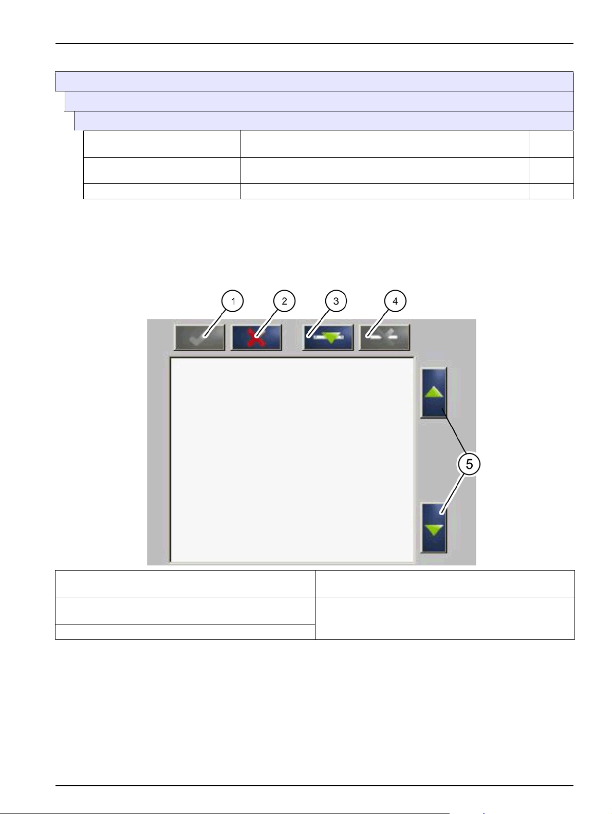
4.5.3 2-Channel RTC103 N-Module VFD (Continued)
RTC MODULES / PROGNOSYS
RTC MODULES
RTC
SOFT-VERSION
RTC MODE
RTC VERSION Shows the software version of the RTC module.
Shows the software version of the RTC communication card
(YAB117) in the sc1000.
Shows the installed RTC module variant, e.g. 1-channel closed-loop
control.
4.6 Select sensors
1. To select sensors and their sequence for the RTC module,
press RTC > CONFIGURE > SELECT SENSOR.
Figure 4 Select sensor
Parameterization and operation
1ENTER — Saves the setting and returns to the
CONFIGURE menu.
2 CANCEL — Returns to the CONFIGURE menu without
saving.
3ADD — Adds a new sensor to the selection.
2. Press
A selection list of all subscribers to the sc1000 network
opens.
4 DELETE — Removes a sensor from the selection.
5UP/DOWN — Moves the sensors up or down.
ADD (Figure 4, item 3).
45
Page 46
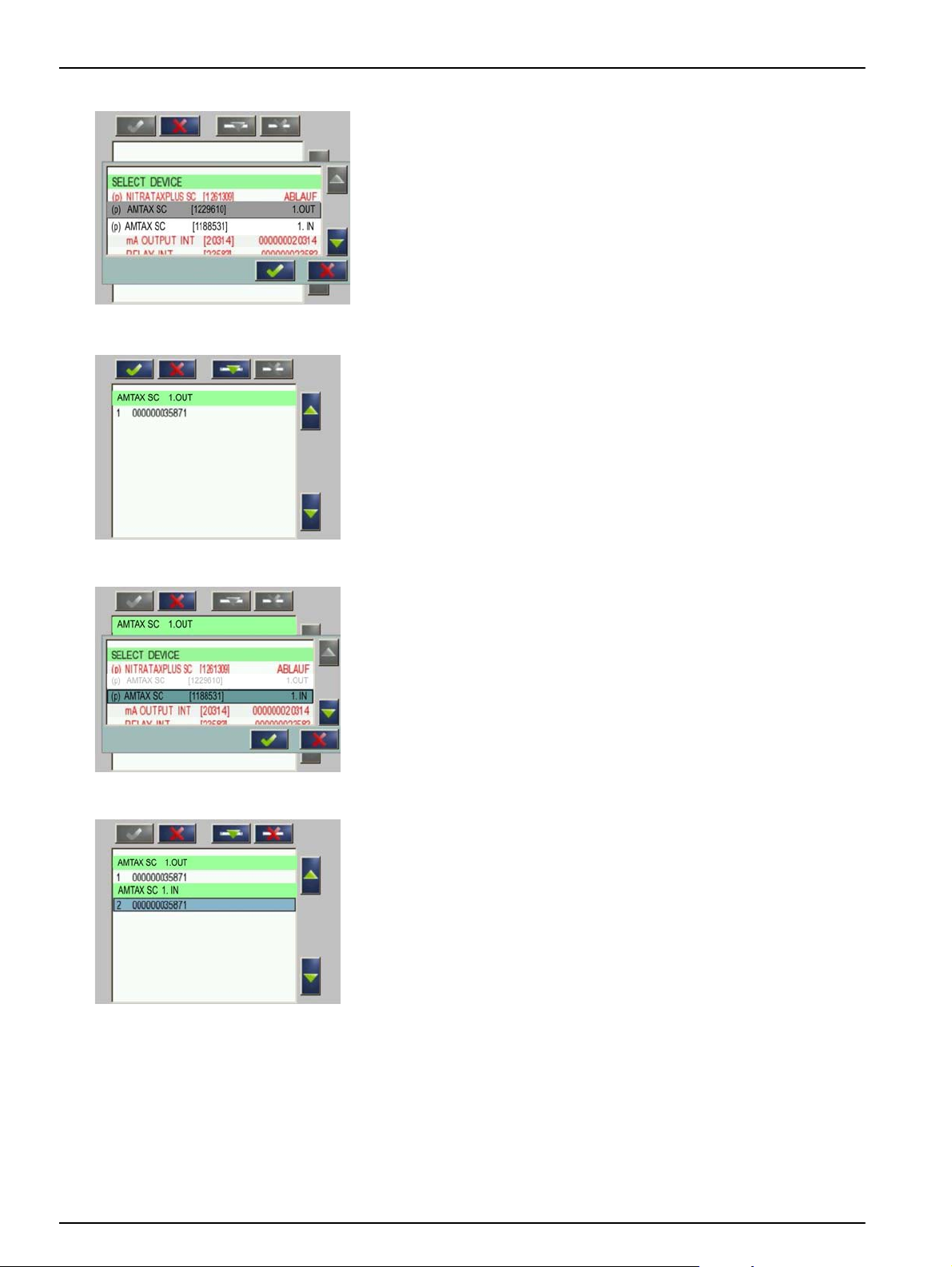
Parameterization and operation
3. Press the required sensor for the RTC module and confirm
by pressing
ENTER below the selection list.
Sensors in black type are available for the RTC module.
Sensors in red type are not available for the RTC module.
Note: For sensors marked (p), PROGNOSYS is available if these
sensors have been selected in conjunction with an RTC module
(refer to the PROGNOSYS user manual).
4. The selected sensor is shown in the sensor list.
Press
ADD (Figure 4, item 3) to open the selection list again.
5. Select the second sensor for the RTC module and confirm
by pressing
Note: Previously selected sensors are shown in gray.
ENTER below the selection list.
The selected sensors are shown in the sensor list.
6. To sort the sensors in the order specified for the RTC
module, press the sensor and use the arrow keys to move it
(Figure 4, item 5).
Press
DELETE (Figure 4, item 4) to remove an incorrect
sensor from the sensor list again.
46
Page 47
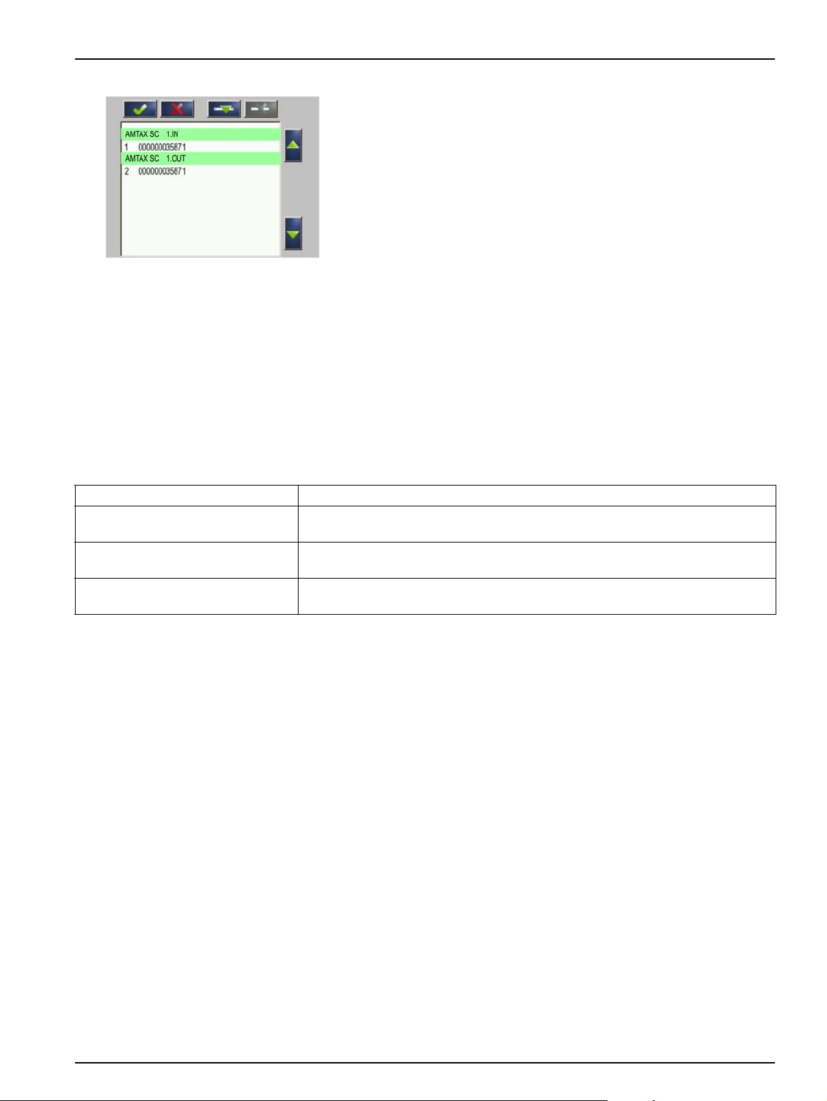
4.7 Control programs
Parameterization and operation
7. Press ENTER (Figure 4, item 1) to confirm the list once it is
finished.
Note: The order of selected sensors has to be defined and
pre-configured by Service of Supplier on CF-card of RTC103 N-Module.
To adapt to local circumstances and the instruments available,
there are 4 different programs available for calculating desired
DO concentration for nitrification
The choice of program depends on the available measurement
signals.
Suitable program has to be selected and pre-configurated on CF
card from RTC103 N-Module by the Service of supplier!
Table 2 Control programs to calculate the desired DO concentration for nitrification
NH4-N influent nitrification Calculate desired DO concentration based on NH4-N load to nitrification, only.
NH4-N influent and TSS
NH4-N influent and NH4-N effluent
NH4-N influent, NH4-N effluent and
TSS
Calculate desired DO concentration based on NH
Sludge retention time
Caluclate desired DO concentration based on NH
effluent concentration.
Caluclate desired DO concentration based on NH
effluent concentration considering the current Sludge retention time.
-N load considering the current
4
-N load to nitrification and NH4-N
4
-N load to nitrification and NH4-N
4
4.8 Automatic program change
If a measurement signal fails, e. g. during an operational fault, an
automatic program change occurs using only the available
measuring signals and replaces the failing measurement by this
fallback strategy. If the measurements are available again after a
failure, it is automatically switched back to the preselected
program. The change between programs occurs with a delay of 5
minutes.
4.9 Explanations of nitrification controller parameters
4.9.1 SRT MODE
Three different types of operation regarding the Sludge Retention
Time (SRT) can be selected
• MANUALLY: The SRT is provided as a manual input to the
controller, if no TSS measurement is available in aeration
tank.
•SRT-RTC: The SRT is provided by a separate SRT-RTC and
forwarded to the RTC103 N-Module.
• TSSml: The SRT is calculated based on MLSS concentration
and the amount of daily removed TSS mass.
47
Page 48

Parameterization and operation
4.9.2 SRT (MANUALLY)
4.9.3 DAILY SURPLUS MASS
4.9.4 COD-TKN RATIO
4.9.5 MIN NITRIFERS CONC.
Manual input for the Sludge Retention Time (SRT [d]).
In case of a failing TSS signal, this is also used as fallback value.
The amount of sludge daily removed from the process. Based on
that amount, the MLSS concentration in the aeration tank and the
aerated volume the SRT is calculated.
This is the assumed COD / TKN ratio. The RTC103 N-Module
considers a certain COD-related amount of NH
incorporated in the bio mass, reducing the amount of NH
nitrified.
Based on the amount of NH4-N nitrified during the last SRT, the
RTC103 N-Module calculates the concentration of nitrifiers in the
activated sludge. This concentration is required to determine the
DO set point. If the calculated concentration is lower than the MIN
NITRIFERS CONC., the MIN NITRIFERS CONC. will be used to
determine the DO set point.
-N to be
4
-N to be
4
4.9.6 MAX NITRIFERS CONC.
4.9.7 MODEL CORRECTION FACT.
4.9.8 SUBSTIT. DO FOR MODEL
4.9.9 NH4-N SETPOINT
Based on the amount of NH4-N nitrified during the last SRT, the
RTC103 N-Module calculates the concentration of nitrifiers in the
activated sludge. This concentration is required to determine the
DO set point. If the calculated concentration is higher than the
MAX NITRIFERS CONC., the MAX NITRIFERS CONC.. will be
used to determine the DO set point.
This factor can be used on order to fine tune the DO
concentration calculated by the model (feed forward part of the
RTC103 N-Module).
If there is a failure in the input signals (NH4-N, TSS, Flow) and
the RTC103 N-Module is not able to calculate the required DO
concentration, the RTC103 N-Module will apply this DO feed
forward set point for all further calculation.
Desired set point of the NH4-N concentration effluent aeration.
4.9.10 P FAKT NH4 (only if NH4-N measurement in effluent is available for feed back control)
Proportional factor for the PD closed loop controller for the NH4-N
concentration effluent aeration.
48
Page 49

Parameterization and operation
4.9.11 INTEGRAL TIME NH4 (only if NH4-N measurement in effluent is available for feed back control)
Integral time for the PID closed loop controller for the NH4-N
concentration in the thickened sludge.
Note: INTEGRAL TIME NH4 is set to “0” to deactivate the integral part
of the PID controller.
4.9.12 DERIVATIVE TIME NH4 (only if NH4-N measurement in effluent is available for feed back control)
Derivation time for the PID closed loop controller for the NH4-N
concentration effluent aeration.
Note: DERIVATIVE TIME NH4 is set to “0” to deactivate the derivative
part of the PID controller.
4.9.13 Min DO
If a calculated DO set point is lower than the MIN DO value, the
DO set point is set to that value.
4.9.14 Max DO
If a calculated DO set point is higher than the MIN DO value, the
DO set point is set to that value.
4.9.15 SMOOTHING
Smooth this calculated DO set-point, for more economical blower
control.
4.10 Explanations of DO CONTROL (For DO control option only)
Note: The configuration for DO control, different kind of blowers,
aeration stages has to be carefully pre-configured from service of
supplier on CF-card of RTC103 N-Module.
4.10.1 P FAKT O2 (For VFD option only)
Proportional factor for the PD closed loop controller for the DO
concentration in the aeration.
4.10.2 DERIVATIVE TIME
Derivative time of the controller
4.10.3 INT PART
Integral part for the closed loop controller for the DO
concentration in the aeration.
4.10.4 DAMPING
Note: INT PART is set to “0” to deactivate the integral part of the
controller.
Damping of DO control - for avoiding quick changes in blowers
control.
49
Page 50

Parameterization and operation
4.10.5 SUBST AERATION
If the oxygen sensor (e.g. LDO) signals a fault, the set aeration
stage is selected (stages 1 to 6).
4.10.6 NUMBER OF STAGES
Number of controlled aeration stages (maximum 6).
4.10.7 VFD P MIN (For DO control without VFD option this is fixed to 100%)
Set minimum speed [%] for VFD controlled blowers.
4.11 INPUTS
There are available two mA input connector for each channel.
The first is the flowrate signal (inlet or effluent of plant or lane).
The second is for the recirculation flow rate or the return sludge
flow rate, depending on which is available and not travelled in
ratio to the inlet/outlet flow rate.
4.11.1 MIN INFLOW
Minimum flow rate of influent according to measurement signal
corresponding to 0/4mA
4.11.2 MAX INFLOW
4.11.3 0/4 to 20mA
4.11.4 MIN RECIRCULATION
4.11.5 MAX RECIRCULATION
4.11.6 0/4 to 20mA
4.11.7 Q RECI RATIO
Maximum flow rate of influent according to measurement signal
corresponding to 20mA
Transfer range of 0/4 to 20mA current loop as set in connected
flow measuring instrument.
Minimum recirculation flow rate according to measurement signal
corresponding to 0/4mA.
Maximum recirculation flow rate of influent according to
measurement signal corresponding to 20mA.
Transfer range of 0/4 to 20mA current loop as set in connected
flow measuring instrument.
50
If the value Q RECI RATIO is “0” the RECI flow is calculated
bases on the mA input signal. If the value is different from “0” the
RECI flow is calculated from the inflow:
Q RECI= Q RECI RATIO * INFLOW
within the limits of MIN RECIRCULATION and MAX
RECIRCULATION.
Page 51

4.11.8 MIN RETURN SLUDGE
4.11.9 MAX RETURN SLUDGE
4.11.10 0/4 to 20mA
4.11.11 Q RETURN RATIO
Parameterization and operation
Minimum return sludge flow rate according to measurement
signal corresponding to 0/4mA.
Maximum return sludge flow rate of influent according to
measurement signal corresponding to 20mA.
Transfer range of 0/4 to 20mA current loop as set in connected
flow measuring instrument.
If the value Q RETURN RATIO is “0” the RAS flow is calculated
bases on the mA input signal. If the value is different from “0” the
RAS flow is calculated from the inflow:
Q RETURN = Q RETURN RATIO * INFLOW
within the limits of MIN RETURN SLUDGE and MAX RETURN
SLUDGE.
4.12 OUTPUTS
4.12.1 MIN DO SETTING (only for option without DO control)
Minimum DO set point corresponding to 0/4mA.
4.12.2 MAX DO SETTING (only for option without DO control)
Maximum DO set point corresponding to 20mA.
4.12.3 0/4 to 20mA
Transfer range of 0/4 to 20mA current loop
• without DO control: for DO setpoint signal.
• with VFD DO control: for VFD blowers signal.
4.13 Volume
4.13.1 Aerated volume
Size of aerated basin (or zone) in m3.
4.14 MODBUS
4.14.1 ADDRESS
4.14.2 DATAORDER
Start address of an RTC within the modbus network.
Specifies the register order within a double word.
Presetting: NORMAL
51
Page 52

Parameterization and operation
4.15 Displayed measurement values and variables
The following measurement values and variables are shown on
the SC1000 display and transferred via fieldbus.
Parameter Unit Description Note
RTC103 N-Module, 1-channel
MEASUREMEN 1 Qin 1 L/s Flow rate aeration lane
MEASUREMEN 2 Qrec 1 L/s
AC T U AT VA R 3 NffO 1 m g / L
AC T U AT VA R 4 Nfb O 1 mg/L
AC T U AT VA R 5 Os etp 1 mg / L
AC T U AT VA R 6 Or eg 1
ACTUAT VAR 7 B_S 1 Stage Aeration stage (B_S1)
ACTUAT VAR 8 A_S 1 % Aeration VFD (A_S 1)
RTC103 N-Module, 2-channel
Flow rate internal recirculation or return
sludge
DO demand calculated for influent
NH
-N load
4
Additional DO demand calculated from
-N effluent concentration
NH
4
DO Setpoint calculated from sum NffO
+ NfbO
Internal calculation value for DO
control
always 0 if no effluent NH
measurement available
always 0 if RTC103 N without DO
control
always 0 if RTC103 N without DO
control
always 0 if RTC103 N without DO
control
-N
4
MEASUREMEN 1 Qin 1 L/s Flow rate aeration lane 1
MEASUREMEN 2 Qrec 1 L/s
MEASUREMEN 3 Qin 2 L/s Flow rate aeration lane 2
MEASUREMEN 4 Qrec 2 L/s
AC T U AT VA R 5 NffO 1 m g / L
AC T U AT VA R 6 Nfb O 1 mg/L
ACTUAT VAR 7 Osetp 1 mg/L DO Setpoint (Osetp1)
ACTUAT VAR 8 Oreg 1 Internal calculation value Oreg1
ACTUAT VAR 9 B_S 1 Aeration stage (B_S1)
ACTUAT VAR 10 A_S 1 Aeration VFD (A_S 1)
AC T U AT VA R 11 NffO 2 mg/L
AC T U AT VA R 12 NfbO 2 mg/L
ACTUAT VAR 13 Osetp 2 mg/L DO Setpoint (Osetp2)
ACTUAT VAR 14 Oreg 2 Internal calculation value Oreg2
ACTUAT VAR 15 B_S 2 Stage Aeration stage (B_S2)
ACTUAT VAR 16 A_S 2 % Aeration VFD (A_S 2)
Flow rate internal recirculation or return
sludge lane 1
Flow rate internal recirculation or return
sludge lane 2
DO demand calc.from influent
load(NffO 1)
Additional DO demand calculated from
NH
-N effluent concentration
4
DO demand calc.from influent load
(NffO 2)
Additional DO demand calculated from
-N effluent concentration
NH
4
always 0 if no effluent NH4-N
measurement available
always 0 if RTC103 N without DO
control
always 0 if RTC103 N without DO
control
always 0 if RTC103 N without DO
control
always 0 if no effluent NH
measurement available
always 0 if RTC103 N without DO
control
always 0 if RTC103 N without DO
control
always 0 if RTC103 N without DO
control
-N
4
52
Page 53

Section 5 Maintenance
5.1 Maintenance schedule
Multiple hazards
Only qualified personnel must conduct the tasks described in this section of the manual.
DANGER
Interval Maintenance task
Visual inspection
CF card 2 years
Battery, type CR2032
Panasonic or Sanyo
Application-specific Check for contamination and corrosion
5 years Replacement
Replacement by manufacturer's service
department (Section 8, page 59)
53
Page 54

Maintenance
54
Page 55

Section 6 Troubleshooting
6.1 Error messages
Possible RTC errors are displayed by the sc controller.
Displayed errors Definition Resolution
Supply RTC with voltage
RTC MISSING
RTC CRC
CHECK KONFIG
RTC FAILURE
No communication between RTC and RTC
communication card
Interrupted communication between RTC and
RTC communication card
The sensor selection of the RTC was deleted
by removal or selection of a new sc1000
participant.
Brief general read/write error on the CF card,
mostly caused by a brief interruption to the
power supply.
Test connection cable
Reset the sc1000 and the RTC (switch so it is
completely voltage free and switch back on)
Make sure +/- connections of the connector
cable between RTC and RTC communication
card in the sc1000 are installed correctly.
Change, if necessary.
MAIN MENU > RTC MODULES /
From
PROGNOSYS > RTC MODULES > RTC >
CONFIGURE > SELECT SENSOR
correct sensor for the RTC again and confirm.
Acknowledge error. If this message is shown
frequently, eliminate the cause of the power
disruptions. If necessary, inform the service
team of the manufacturer (Section 8).
, select the
6.2 Warnings
Possible RTC sensor warnings are displayed by the sc controller.
Displayed warnings Definition Resolution
The RTC menu SET DEFAULTS was opened.
MODBUS ADDRESS
PROBE SERVICE A configured sensor is in service status. The sensor must exit service status.
This deleted the Modbus address of the RTC in
the sc1000.
MAIN MENU > RTC MODULES / PROGNOSYS >
RTC MODULES > RTC > CONFIGURE > MODBUS
> ADDRESS
correct MODBUS address.
: Access this menu and set the
6.3 Wear parts
Component Quantity Service life
CF card, type for RTC module 1 2 years
Battery, type CR2032 Panasonic or Sanyo 1 5 years
55
Page 56

Troubleshooting
56
Page 57

Section 7 Replacement parts and accessories
7.1 Replacement Parts
Description Cat. No
DIN rail NS 35/15, punched according to DIN EN 60715 TH35, made of galvanized steel.
Length: 35 cm (13.78 in.)
Transformer 90–240 V AC/24 V DC 0.75 A, module for top hat rail assembly LZH166
Terminal for 24 V connection without power supply LZH167
Grounding terminal LZH168
SUB-D connector LZH169
C2 circuit breaker LZH170
CPU base module with Ethernet port, passive ventilation element. (CX1010-0021) and
RS422/485 connection module (CX1010-N031)
Power supply module, consisting of a bus coupler and a 24 V terminal module (CX1100-0002) LZH172
Digital output module 24 V DC (2 outputs) (KL2032) LZH173
Digital output module 24 V DC (4 outputs) (KL2134) LZH174
Analog output module (1 output) (KL4011) LZH175
Analog output module (2 outputs) (KL4012) LZH176
Analog input module (1 input) (KL3011) LZH177
Digital input module 24 V DC (2 inputs) (KL1002) LZH204
Digital output module 24 V DC (8 outputs) (KL2408) LZH205
Digital output module 24 V DC (16 outputs) (KL2809) LZH206
Bus termination module (KL9010) LZH178
RTC communication card YAB117
CF card, type for RTC module LZY748-00
LZH165
LZH171
57
Page 58

Replacement parts and accessories
58
Page 59

Section 8 Contact information
HACH Company
World Headquarters
P.O. Box 389
Loveland, Colorado
80539-0389 U.S.A.
Tel (800) 227-HACH
(800) -227-4224
(U.S.A. only)
Fax (970) 669-2932
orders@hach.com
www.hach.com
HACH LANGE GMBH
Willstätterstraße 11
D-40549 Düsseldorf
Tel. +49 (0)2 11 52 88-320
Fax +49 (0)2 11 52 88-210
info@hach-lange.de
www.hach-lange.de
HACH LANGE GMBH
Rorschacherstrasse 30a
CH-9424 Rheineck
Tel. +41 (0)848 55 66 99
Fax +41 (0)71 886 91 66
info@hach-lange.ch
www.hach-lange.ch
Repair Service in the
United States:
HACH Company
Ames Service
100 Dayton Avenue
Ames, Iowa 50010
Tel (800) 227-4224
(U.S.A. only)
Fax (515) 232-3835
HACH LANGE LTD
Pacific Way
Salford
GB-Manchester, M50 1DL
Tel. +44 (0)161 872 14 87
Fax +44 (0)161 848 73 24
info@hach-lange.co.uk
www.hach-lange.co.uk
HACH LANGE FRANCE
S.A.S.
8, mail Barthélémy Thimonnier
Lognes
F-77437 Marne-La-Vallée
cedex 2
Tél. +33 (0) 820 20 14 14
Fax +33 (0)1 69 67 34 99
info@hach-lange.fr
www.hach-lange.fr
Repair Service in Canada:
Hach Sales & Service
Canada Ltd.
1313 Border Street, Unit 34
Winnipeg, Manitoba
R3H 0X4
Tel (800) 665-7635
(Canada only)
Tel (204) 632-5598
Fax (204) 694-5134
canada@hach.com
HACH LANGE LTD
Unit 1, Chestnut Road
Western Industrial Estate
IRL-Dublin 12
Tel. +353(0)1 460 2522
Fax +353(0)1 450 9337
info@hach-lange.ie
www.hach-lange.ie
HACH LANGE NV/SA
Motstraat 54
B-2800 Mechelen
Tel. +32 (0)15 42 35 00
Fax +32 (0)15 41 61 20
info@hach-lange.be
www.hach-lange.be
Repair Service in
Latin America, the
Caribbean, the Far East,
Indian Subcontinent, Africa,
Europe, or the Middle East:
Hach Company World
Headquarters,
P.O. Box 389
Loveland, Colorado,
80539-0389 U.S.A.
Tel +001 (970) 669-3050
Fax +001 (970) 669-2932
intl@hach.com
HACH LANGE GMBH
Hütteldorfer Str. 299/Top 6
A-1140 Wien
Tel. +43 (0)1 912 16 92
Fax +43 (0)1 912 16 92-99
info@hach-lange.at
www.hach-lange.at
DR. LANGE NEDERLAND
B.V.
Laan van Westroijen 2a
NL-4003 AZ Tiel
Tel. +31(0)344 63 11 30
Fax +31(0)344 63 11 50
info@hach-lange.nl
www.hach-lange.nl
HACH LANGE APS
Åkandevej 21
DK-2700 Brønshøj
Tel. +45 36 77 29 11
Fax +45 36 77 49 11
info@hach-lange.dk
www.hach-lange.dk
HACH LANGE LDA
Av. do Forte nº8
Fracção M
P-2790-072 Carnaxide
Tel. +351 214 253 420
Fax +351 214 253 429
info@hach-lange.pt
www.hach-lange.pt
HACH LANGE KFT.
Vöröskereszt utca. 8-10.
H-1222 Budapest XXII. ker.
Tel. +36 1 225 7783
Fax +36 1 225 7784
info@hach-lange.hu
www.hach-lange.hu
HACH LANGE AB
Vinthundsvägen 159A
SE-128 62 Sköndal
Tel. +46 (0)8 7 98 05 00
Fax +46 (0)8 7 98 05 30
info@hach-lange.se
www.hach-lange.se
HACH LANGE SP. ZO.O.
ul. Krakowska 119
PL-50-428 Wrocław
Tel. +48 801 022 442
Zamówienia: +48 717 177 707
Doradztwo: +48 717 177 777
Fax +48 717 177 778
info@hach-lange.pl
www.hach-lange.pl
HACH LANGE S.R.L.
Str. Căminului nr. 3,
et. 1, ap. 1, Sector 2
RO-021741 Bucureşti
Tel. +40 (0) 21 205 30 03
Fax +40 (0) 21 205 30 17
info@hach-lange.ro
www.hach-lange.ro
HACH LANGE S.R.L.
Via Rossini, 1/A
I-20020 Lainate (MI)
Tel. +39 02 93 575 400
Fax +39 02 93 575 401
info@hach-lange.it
www.hach-lange.it
HACH LANGE S.R.O.
Zastrčená 1278/8
CZ-141 00 Praha 4 - Chodov
Tel. +420 272 12 45 45
Fax +420 272 12 45 46
info@hach-lange.cz
www.hach-lange.cz
HACH LANGE
8, Kr. Sarafov str.
BG-1164 Sofia
Tel. +359 (0)2 963 44 54
Fax +359 (0)2 866 15 26
info@hach-lange.bg
www.hach-lange.bg
HACH LANGE SPAIN S.L.U.
Edificio Seminario
C/Larrauri, 1C- 2ª Pl.
E-48160 Derio/Bizkaia
Tel. +34 94 657 33 88
Fax +34 94 657 33 97
info@hach-lange.es
www.hach-lange.es
HACH LANGE S.R.O.
Roľnícka 21
SK-831 07 Bratislava –
Vaj nory
Tel. +421 (0)2 4820 9091
Fax +421 (0)2 4820 9093
info@hach-lange.sk
www.hach-lange.sk
HACH LANGE SU
ANALİZ SİSTEMLERİ
LTD.ŞTİ.
Ilkbahar mah. Galip Erdem
Cad. 616 Sok. No:9
TR-Oran-Çankaya/ANKARA
Tel. +90312 490 83 00
Fax +90312 491 99 03
bilgi@hach-lange.com.tr
www.hach-lange.com.tr
59
Page 60

Contact information
HACH LANGE D.O.O.
Fajfarjeva 15
SI-1230 Domžale
Tel. +386 (0)59 051 000
Fax +386 (0)59 051 010
info@hach-lange.si
www.hach-lange.si
HACH LANGE OOO
Finlyandsky prospekt, 4A
Business Zentrum “Petrovsky
fort”, R.803
RU-194044, Sankt-Petersburg
Tel. +7 (812) 458 56 00
Fax. +7 (812) 458 56 00
info.russia@hach-lange.com
www.hach-lange.com
ΗΑCH LANGE E.Π.Ε.
Ηρακλείτου 3
GR-15235 Χαλάνδρι
Τηλ . +30 210 7777038
Fax +30 210 7777976
info@hach-lange.gr
www.hach-lange.gr
HACH LANGE D.O.O.
Ivana Severa bb
HR-42 000 Varaždin
Tel. +385 (0) 42 305 086
Fax +385 (0) 42 305 087
info@hach-lange.hr
www.hach-lange.hr
HACH LANGE MAROC
SARLAU
Villa 14 – Rue 2 Casa
Plaisance
Quartier Racine Extension
MA-Casablanca 20000
Tél. +212 (0)522 97 95 75
Fax +212 (0)522 36 89 34
info-maroc@hach-lange.com
www.hach-lange.ma
60
Page 61

Section 9 Warranty and liability
The manufacturer warrants that the supplied product is free of material and manufacturing
defects, and undertakes to repair or to replace any defective parts without charge.
The warranty period is 24 months. If a maintenance contract is taken out within 6 months
of purchase, the warranty period is extended to 60 months.
With the exclusion of further claims, the supplier is liable for defects, including the lack of
assured properties, as follows: all parts that, within the warranty period calculated from the
day of the transfer of risk, can be demonstrated to have become unusable or that can only
be used with significant limitations owing to circumstances prior to transfer of risk, in
particular due to incorrect design, substandard materials or inadequate finish, shall be
repaired or replaced at the supplier's discretion. The identification of such defects must be
reported to the supplier in writing as soon as possible, but no later than 7 days after the
discovery of the fault. If the customer fails to notify the supplier, the product is considered
approved despite the defect. Further liability for indirect or direct damages is not accepted.
If device-specific maintenance- or inspection work prescribed by the supplier is to be
performed within the guarantee period by the customer (maintenance) or by the supplier
(inspection) and these requirements are not met, claims for damages that result from
non-observance of these requirements are void.
Further claims, in particular for consequential damages, cannot be made.
Wear and damage caused by improper handling, incorrect installation or non-designated
use are excluded from this clause.
The process instruments of the manufacturer have proven their reliability in many
applications and are therefore often used in automatic control loops to enable the most
economical and efficient operation of the relevant process.
To avoid or limit consequential damage, it is therefore recommended that the control loop
be designed such that an instrument malfunction results in an automatic changeover to
the backup control system. This guarantees the safest operating condition both for the
environment and the process.
61
Page 62

Warranty and liability
62
Page 63

Appendix A MODBUS address setting
The same slave address must be set for Modbus communication both on the sc1000
controller display and on the RTC103 N-Module. Since 20 slave numbers are reserved for
internal purposes, the following numbers are available for assignment:
1, 21, 41, 61, 81, 101…
The start address 41 is preset at the factory.
NOTICE
If this address is to be or must be changed because, for example, it has already been allocated
for another RTC module the changes must be made both on the sc1000 controller and on the CF
card of the RTC module.
This can only be done by the manufacturer service department (Section 8)!
63
Page 64

MODBUS address setting
64
Page 65

Index
A
Address setting ........................................................ 63
Aeration element ...................................................... 11
B
Base module ............................................................ 11
Battery compartment ................................................ 11
Bus coupler .............................................................. 11
C
Control programs ..................................................... 47
Controller behavior ................................................... 13
E
Embedded PC ............................................................ 7
Error messages ........................................................ 55
Ethernet port ............................................................ 11
Expansion slot ............................................................ 7
F
Flash memory ............................................................ 7
I
Input
analog ..................................................................... 7
Input module ............................................................ 12
Interfaces ................................................................... 7
M
Maintenance schedule ............................................. 53
Module
Base ...................................................................... 11
Bus termination ..................................................... 12
Input ...................................................................... 12
Output ................................................................... 12
Terminal ................................................................ 11
O
Operating system ....................................................... 7
Output
digital ...................................................................... 7
Output module .......................................................... 12
P
Precautionary labels ................................................... 9
S
Safety information ...................................................... 9
Slave address .......................................................... 63
Supply voltage .......................................................... 15
T
Technical data ............................................................ 7
Terminal module ....................................................... 11
Theory of operation .................................................. 12
W
Warnings .................................................................. 55
Warranty and liability ................................................ 61
65
Page 66

Index
66
 Loading...