

Page 1

DOC023.52.90351
PROGNOSYS
05/2014, Edition 7
User Manual
Page 2

Page 3

Table of Contents
General information..................................................................................................3
Safety information........................................................................................................3
Use of hazard information....................................................................................3
Precautionary labels.............................................................................................3
Product overview.........................................................................................................4
Product components....................................................................................................4
Installation.....................................................................................................................4
PROGNOSYS communication card............................................................................4
Install the RTC/PROGNOSYS communication card
.................................................... 4
User interface and navigation..............................................................................4
Keypad description......................................................................................................4
Startup............................................................................................................................. 5
Add a sensor................................................................................................................ 5
Sort the sensors (RTC modules only)..................................................................6
Delete a sensor from the list.................................................................................7
Operation.......................................................................................................................7
PROGNOSYS indicator bars.......................................................................................7
Display description....................................................................................................... 8
Measurement value indicator....................................................................................... 9
Service indicator..........................................................................................................9
See the message lists.................................................................................................. 9
Configure the general settings...................................................................................10
Configure the sensor.................................................................................................11
Service and measurement value indicator messages.............................11
AMTAX sc and PHOSPHAX sc.................................................................................11
NITRATAX plus sc.....................................................................................................13
ANISE sc/AISE sc/NISE sc........................................................................................ 13
SOLITAX sc...............................................................................................................15
LDO Probe, Model 2..................................................................................................16
Troubleshooting.......................................................................................................17
Replacement parts...................................................................................................18
Warranty.......................................................................................................................18
PROGNOSYS register............................................................................................18
Index...............................................................................................................................21
1
Page 4

Table of Contents
2
Page 5
General information
In no event will the manufacturer be liable for direct, indirect, special, incidental or consequential
damages resulting from any defect or omission in this manual. The manufacturer reserves the right to
make changes in this manual and the products it describes at any time, without notice or obligation.
Revised editions are found on the manufacturer’s website.
Safety information
N O T I C E
The manufacturer is not responsible for any damages due to misapplication or misuse of this product including,
without limitation, direct, incidental and consequential damages, and disclaims such damages to the full extent
permitted under applicable law. The user is solely responsible to identify critical application risks and install
appropriate mechanisms to protect processes during a possible equipment malfunction.
Please read this entire manual before unpacking, setting up or operating this equipment. Pay
attention to all danger and caution statements. Failure to do so could result in serious injury to the
operator or damage to the equipment.
Make sure that the protection provided by this equipment is not impaired. Do not use or install this
equipment in any manner other than that specified in this manual.
Use of hazard information
Indicates a potentially or imminently hazardous situation which, if not avoided, will result in death or serious injury.
Indicates a potentially or imminently hazardous situation which, if not avoided, could result in death or serious
injury.
Indicates a potentially hazardous situation that may result in minor or moderate injury.
Indicates a situation which, if not avoided, may cause damage to the instrument. Information that requires special
emphasis.
Precautionary labels
Read all labels and tags attached to the instrument. Personal injury or damage to the instrument
could occur if not observed. A symbol on the instrument is referenced in the manual with a
precautionary statement.
This symbol, if noted on the instrument, references the instruction manual for operation and/or safety
information.
D A N G E R
W A R N I N G
C A U T I O N
N O T I C E
This symbol indicates that a risk of electrical shock and/or electrocution exists.
Electrical equipment marked with this symbol may not be disposed of in European domestic or public
disposal systems. Return old or end-of-life equipment to the manufacturer for disposal at no charge to
the user.
English 3
Page 6

Product overview
PROGNOSYS (Prognosis System) is a software package used to monitor and show the reliability of
measurement values and to identify pending maintenance tasks. This software is available for sc
sensors. The sc1000 controller operates and configures the software.
The controller display will show horizontal bars as a measurement value indicator and as a service
indicator for the remaining time until the next maintenance task. The green, yellow and red indicators
show and identify the status of each sensor. Each sensor has an individual screen.
The service indicator is a prediction about future maintenance and service tasks, which are based on
the current sensor status. The service messages supply information on maintenance tasks that the
user must complete (e.g., to clean the sensor or replace the reagents). In addition, service tasks are
shown that the service technician must complete. All service messages have a countdown period
with sufficient time to contact a service technician or to order a replacement part.
Product components
Make sure that all components have been received. If any items are missing or damaged, contact the
manufacturer or a sales representative immediately.
PROGNOSYS can only be used with an sc1000 controller that has an RTC communication card or a
PROGNOSYS card installed. The PROGNOSYS files for the different sc sensors are kept on the
sc1000 controller.
To use PROGNOSYS without an RTC module, install a PROGNOSYS communication card on an
sc1000 controller. Refer to Replacement parts on page 18
.
Installation
PROGNOSYS communication card
If a PROGNOSYS communication card is installed, the controller display shows RTC
MODULES/PROGNOSYS in the main menu.
Install the RTC/PROGNOSYS communication card
Install an RTC or a PROGNOSYS communication card on an sc1000 controller with the software
version 3.20 or higher.
The controller operates a maximum of three communication cards at the same time. Each
PROGNOSYS communication card manages a maximum of eight sensors.
Refer to the applicable documentation for the RTC or PROGNOSYS communication card installation.
User interface and navigation
Keypad description
Refer to Figure 1 for the keypad description and navigation information.
4 English
Page 7
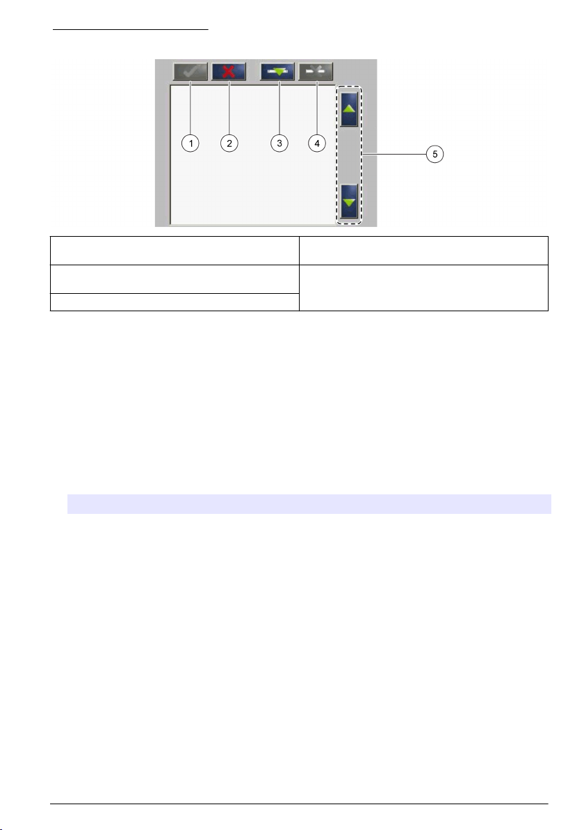
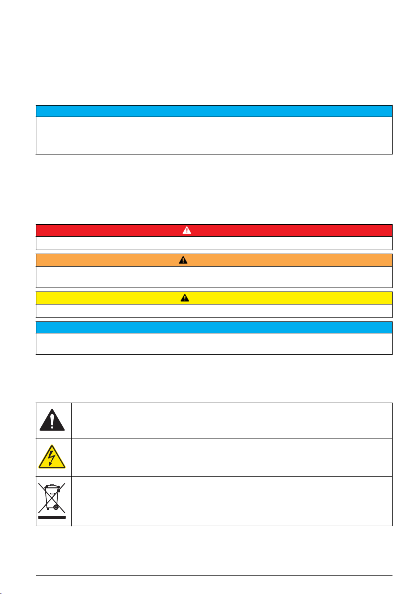
Figure 1 Keypad description
1 Enter: Saves the setting and exits the current
screen to the CONFIGURE menu
2 Cancel: Exits the current screen to the
CONFIGURE menu without saving the setting
3 Add: Adds a new sensor to the selection
4 Delete: Removes a sensor from the selection
5 UP and DOWN arrows: Moves the sensors up or
down the list
Startup
Add a sensor
Note: PROGNOSYS is not available for all sensors. Only newer sensor models can use the PROGNOSYS
function.
Note: Make sure that an RTC or a PROGNOSYS communication card is installed in the sc1000 sensor module.
When an RTC or PROGNOSYS communication card is installed, PROGNOSYS files are available
for different sc sensors. Do the steps that follow to add a sensor. Refer to Figure 2.
1. Connect the controller. Refer to the controller documentation.
2. Select an option.
Option Description
For
RTC/PROGNOSYS
card
For PROGNOSYS
card
3. Push Add. A list with all network connections opens.
4. Select the applicable sensor for the RTC or PROGNOSYS module and push Enter. The sensor is
shown in the sensor list.
Note: Sensor names with black font are available for an RTC module. Sensor names with red font are not
available for an RTC module. A sensor name identified with a "(p)" is available for PROGNOSYS.
5. Push Add to add more sensors from the list.
Sensors that are selected before are shown in gray. Refer to Figure 3
on page 7 to put in order or delete a sensor.
6. Push Enter to accept the list.
Select MAIN MENU>RTC MODULES/PROGNOSYS>RTC
MODULES>RTC>CONFIGURE>SELECT SENSOR
Select MAIN MENU>RTC
MODULES/PROGNOSYS>PROGNOSYS>CONFIGURATION>PROGNOSYS>SELECT
SENSOR
on page 7 or Figure 4
English 5
Page 8
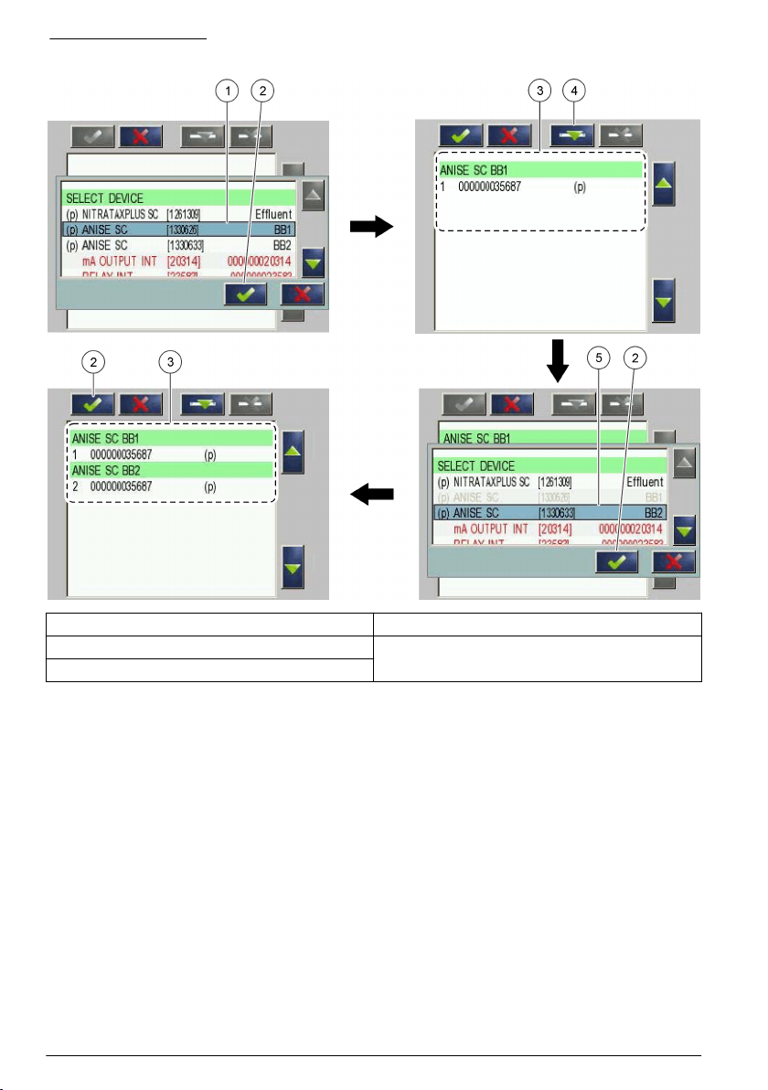
Figure 2 Add sensors
1 Select sensor 4 Add
2 Accept 5 Select additional sensor
3 Sensor list
Sort the sensors (RTC modules only)
The sensor sequence is programmed in the RTC module for the measurement values. To sort the
sensors in the order specified for the RTC module, move the selected sensor with the UP and
DOWN arrows. Refer to Figure 3.
6 English
Page 9

Figure 3 Sort the sensors
1 Select sensor 2 UP and DOWN arrows
Delete a sensor from the list
To delete a selected sensor from the list, push Delete. Refer to Figure 4.
Figure 4 Delete a sensor
1 Select sensor 3 Delete the sensor
2 Go back without changes
Operation
PROGNOSYS indicator bars
If PROGNOSYS is installed, two additional horizontal bars show in the top right-hand corner of the
measurement screen. The top bar is the measurement value indicator. The bottom bar is the service
indicator. If no bars show up, refer to Troubleshooting on page 17
the value in the indicator identifies the sensor status. Refer to Table 1.
. The position of the cursor and
English 7
Page 10

Table 1 Color definitions
Color Definition
Green The sensor is in operation with no warnings, errors or reminders.
Yellow The sensor is in operation with active warnings or reminders.
Red The measurement value is invalid or immediately complete a service task.
Blank (background
color)
The measurement indicator (top bar) shows a possible measurement value deviation,
but the value is still within the permitted tolerance.
The service indicator (bottom bar) shows an upcoming maintenance task which
includes a countdown period. Set the countdown period between 7 and 14 days.
No data is available or the RTC/PROGNOSYS communication card was removed.
Display description
The measurement value indicator is not a linear degrading indicator because of the sensor special
model based calculation.
Measurement zone Range
Green zone 100 to 75%
Yellow zone <75 to 50%
Red zone <50 to 0%
The exact status shows with an additional vertical cursor. A maximum of four measurement values
show if multiple sensors are installed on the sc1000. The indicators are shown for each installed
sensor in the top right-hand corner.
If only a frame around the background color shows and no traffic light colors, no data is available for
the sensor. If no bars are shown, refer to Troubleshooting on page
Figure 6 for examples shown on the display.
17. Refer to Figure 5 and
Figure 5 Display overview for one sensor
1 Symbol for the service indicator 3 Cursor with exact status of the measurement value
2 Symbol for the measurement value indicator 4 Cursor with exact status of the service indicator
indicator
8 English
Page 11

Figure 6 Display overview for four sensors
1 Sensor 1 3 Sensor 3
2 Sensor 2 4 Sensor 4
Measurement value indicator
If the sensor condition changes, the measurement value indicator changes. A deterioration of the
measurement value indicator level in the top bar can change the color in the bottom service bar.
Pending maintenance tasks do not have an immediate effect on the measurement value indicator
(e.g., to replace the reagents).
A change in color from green to yellow shows that the reliability of the measurement value
decreased. There can be a deviation in the measurement value, but the value is still within the
permissible tolerance.
The top bar shows the measurement value indicator in [%].
If the vertical cursor is in the red area (<50%), the measurement value indicator is not in the
permitted range. These measurement values must not be used for control purposes in processes.
Refer to Service and measurement value indicator messages on page
When the errors are successfully solved, the color automatically changes from red to green.
11 for troubleshooting.
Service indicator
The service indicator shows the maintenance status of the sensor. The bottom bar shows the
number of days that remain until a maintenance task must be completed. The date and time for the
next maintenance task (e.g., cleaning or calibration is calculated). Service tasks with no countdown
show immediately and change the color from green to red (e.g., an interruption of communication
over a prolonged period or moisture in the sensor).
The number of days until the next maintenance tasks is shown in the applicable message list. Refer
to Configure the sensor on page 11.
See the message lists
The messages in the measurement value indicator list show the type of incident with a percentage
value. The percentage shows the influence degree on the probability that the measurement value is
correct. The measurement value indicator is the product of the first incident multiplied by the average
of all possible incidents. Notice that incidents with 100% are not shown in the list but are part of the
calculation.
Refer to Service and measurement value indicator messages on page 11 for a general overview of
the instrument-specific messages.
English 9
Page 12

Example: A probe has 10 possible indicators. Three parameters show indicators of 75%, 90% and
90%. The hidden indicators have a value of 100%. The worst incident is changed to a decimal
number: 0.75. The average of the other incidents is 0.98. The overall indicator is 0.75 × 0.98 = 0.73.
The overall indicator for the example is 73%. Refer to Table 2.
The message list specifies the type of the maintenance task with the number of days left until the
maintenance must be completed. The example shows to replace the cleaning solution today. The
reagents should be used up in six days. Refer to Table 3.
1. Push PROGNOSYS to access the applicable menu.
2. Push the top bar.
The measurement value indicator message list shows.
3. Push the bottom bar.
The service indicator message list shows.
Table 2 Example of a measurement value indicator list
Measurement indicator Measurement value indicator value in %
Insufficient light 75
Analysis: too cold 90
Analysis: moisture 90
Table 3 Example of a service indicator list
Service indicator Time in days
clean Solu days 1 day
Reagent days 6 days
Configure the general settings
Configure service messages to send emails to the manufacturer telemetry service and to a maximum
of four freely-configured email address(es). This email gives information about important changes in
the measurement indicator and about pending maintenance tasks.
In addition, the length of the "YELLOW PHASE" of the service indicator can be configured. The
yellow phase setting applies to all sensors connected to the controller that are monitored by
PROGNOSYS. The setting specifies the duration of the yellow maintenance countdown phase in
days. For maintenance tasks that are not often necessary, the user can extend the yellow phase to
operate on a self-sufficient basis.
1. Push MAIN MENU>SERVICE>PROGNOSYS.
2. Select an option.
Option Description
SERVICE
MESSAGE
YELLOW PHASE Sets the number of days that remain of the yellow phase to complete the next
Sets the number of days to send an email before a color change in the service indicator
will occur. Range: –1 to –14 days (default = –7 days)
maintenance task (when the color changes from yellow to red). Range: 1 to 14 days
(default = 14 days)
10 English
Page 13

Configure the sensor
Use the PROGNOSYS menu to monitor specific settings or to change the blink mode.
1. Push MAIN MENU>RTC MODULES/PROGNOSYS>PROGNOSYS.
2. Select the applicable sensor.
3. Select an option.
Option Description
MEAS. INDICATOR Shows the measurement indicator bar in %.
DETAILS Shows the message list for the measurement indicator. Example: R<M—shows if
SERVICE INDICATOR Shows the number of days that remain until a maintenance task must be completed.
DETAILS Shows the message list for the service indicator. Example: replace the wiper profile:
DEVICE Shows the sensor name.
LOCATION Shows the location name where the sensor is used.
PROGNOSYS VERS. Shows the PROGNOSYS software version.
BLINK MODE MEAS< Enters the measurement indicator value in %. The measurement indicator bar
BLINK MODE SERV< Enters individual number of days for a maintenance task. The service indicator bar
the reference signal is smaller than the measurement signal in %. MEAS EXT—
shows the absorbance value in %.
1 day or replace the seals: 42 days
flashes when the value decreases below the given value. Make sure to enter a
higher value when the measurement is related to a control system or a sensitive
parameter. Range: 0 to 100% (default = 0%)
flashes when the value decreases below the given value. Range: 0 to 200 days
(default = 0 days)
Service and measurement value indicator messages
W A R N I N G
For safe use of the instrument, obey the precautions and the instructions in the sensor documentation.
This list gives a general overview for the service and measurement value indicator messages. Refer
to the sensor documentation for a more detailed list of maintenance messages.
AMTAX sc and PHOSPHAX sc
Message Possible cause Solution
Instrument error The instrument caused an error
Instrument
warning
Warm-up phase The inside of the instrument is too
Cooling down The instrument is overheated and
message.
The instrument caused a warning
message.
cold (e.g., the enclosure door was
open at low external
temperatures).
is cooling-down. If the instrument
version has a filter probe, the
compressor is deactivated in this
phase.
Examine the error message on the controller. Refer to
the sensor documentation for solutions. Make sure that
the error is shown in the service menu and push
START.
Wait until the warm-up phase is completed. If the startup temperature was higher, the warm-up phase can
vary from a few minutes to an hour.
• Wait until the cooling-down phase is completed.
•
Make sure that no blockage of the vent is caused.
• Clean or change the air filter.
• Complete a function test on the fan.
• Specify the correct operating temperature.
English 11
Page 14

Message Possible cause Solution
Pump piston
replacement
If 0 day is shown, the time for the
pump piston is expired.
• Contact technical support immediately to replace the
pump piston, so that the instrument operates
correctly.
• Set the counter when the pump piston is replaced.
Air filters clean The maintenance for the air filter
Reagent days Shows the days that remain to
clean Solu days Shows the days that remain to
Standards days
(AMTAX sc only)
Electrolyte days
(AMTAX sc only)
Compressor
replacement
is necessary.
replace the reagent.
replace the cleaning solution.
Shows the days that remain to
replace the calibration standard.
Shows the days that remain to
change the electrolyte in the
electrode and the membrane cap.
The time for the compressor is
expired. For instruments with a
filter probe only.
• Examine the air filter condition.
• Rinse the air filter with water or replace it.
• Examine and clean the air inlet and outlet on the
back of the instrument.
• Use tweezers to remove contamination from the air
filter support.
• Complete the air filter maintenance task correctly so
that the instrument does not overheat.
• Set the counter when the maintenance task is
completed.
• Replace the reagents on time.
• Set the counter when the maintenance task is
completed.
• Replace the cleaning solution on time.
• Set the counter when the maintenance task is
completed.
• Replace the calibration solution on time.
• Set the counter when the maintenance task is
completed.
• Change the electrolyte in the electrode and the
membrane cap on time.
• Set the counter when the maintenance task is
completed.
• Replace the compressor.
• Set the counter when the maintenance task is
completed.
Clean filtration
modules
Humidity probe % Humidity is in the enclosure.
Service filter
probe required
Shows the days that remain to
clean the filtration modules. For
instruments with a filter probe
only.
Shows the time that remains to
replace the filter probe.
Shows the days that remain to
replace the pump membrane in
the filter probe.
12 English
• Clean the filtration modules. Replace the filtration
module if the cleaning is not sufficient.
• Set the counter when the maintenance task is
completed.
Contact technical support immediately for the filter
probe maintenance and desiccant replacement, so that
the instrument operates correctly.
• Contact technical support immediately for the filter
probe maintenance and pump membrane
replacement, so that the instrument operates
correctly.
• Set the counter when the pump membrane is
replaced.
Page 15

NITRATAX plus sc
Message Possible cause Solution
Sensor,
Application
check
R<M
The signal level is too low. The sensor
possibly has a dirty window. The selected
path length is too long (if applicable). The
solid concentration or the turbidity in the
measurement medium can be too high.
• Clean sensor window fully.
• Examine the wiper.
• Examine the measuring medium with a
diluted sample.
• Contact technical support.
meas ext The measurement absorbance is too high.
ref ext The path length is too long. The wiper does
Wiper blocked The wiper is mechanically blocked. The
Wiper position
unknown
Moist Moisture in the sensor is over limit: the
R too high The automatic zeroing is not correct. Contact technical support for a zero point
Replace
shaftseals
Replace profile The time for wiper profile cycles is expired.
Motor cycle The time for motor cycles is expired. Contact technical support to replace the wiper
Flash lamp
replace
Replace seals The annual change of the sensor enclosure
Error Collective error message Examine the error message on the controller.
Warning Collective warning message
The measurement range is too high because
the signal level is too low. The sensor
possibly has a dirty window. Interferences
can be caused by other substances.
not operate correctly. The absorbance is too
high because of nitrate concentration or other
UV-absorbing materials.
measurement window is not clean anymore.
No sample is pulled in the instrument. The
wiper is possibly in front of the window.
desiccant is expired. There is possibly a
problem with the gasket set for the sensor
sleeve or the wiper axle.
The time for the wiper axle gasket cycles is
expired.
The time for flashes is expired. Contact technical support to replace the flash
gasket is necessary.
• Clean sensor window fully.
• Examine the wiper.
• Examine the solid content of sample.
• Use a cuvette test to examine the nitrate
concentration. If the EM/ER values are
>2.74, use a smaller path length.
• Contact technical support.
• Examine and clean the measurement
window fully.
• Complete a wiper test and do a stop position
test.
• Contact technical support.
Contact technical support immediately to
replace the gasket, so that the instrument
operates correctly.
calibration.
Contact technical support to replace for a wiper
axle gasket.
• Replace the wiper profile.
• Set the counter when the maintenance task
is completed.
motor.
lamp.
Contact technical support to replace the sensor
enclosure gasket.
Refer to the sensor documentation for
solutions.
ANISE sc/AISE sc/NISE sc
1
Message
Instrument error The instrument caused an
Instrument warning The instrument caused a
Possible cause Solution
error message.
warning message.
Examine the error message on the controller. Refer to
the sensor documentation for solutions.
English 13
Page 16

Message
1
Possible cause Solution
RFID-Data not valid The RFID calibration data for
the cartridge could not be
read.
Reference potential
uncertain
The data supplied by the
reference system for the
cartridge is not reliable.
Initial matrix
correction required
When a new cartridge is
installed, a matrix correction is
necessary after 24 hours.
Matrix correction
NH4 necessary
Matrix correction
NO3 necessary
A matrix correction for NH4 is
necessary.
A matrix correction for NO3 is
necessary.
Replace cartridge The time (one year) for the
cartridge is expired.
no contact Ref1 Problem with the contact
no contact Ref2
between sensor and reference
system.
no contact NH4
no contact NO3
no contact K+
no contact Cl-
Humidity cartridge
contacts
There is humidity between the
sensor and the cartridge.
Enter the sensor code for the temporary sensor
operation manually, then replace the cartridge.
Examine the measurement values and if necessary,
replace the cartridge.
Complete a one-point matrix correction for NH4-N and
NO3-N. Complete a one-point matrix correction for a
higher measurement accuracy for small values for NH4N
+K and NO3N +Cl.
Complete a one-point matrix correction (MX1) or value
correction (VC1) for NH4. If the calibration is good in
comparison to the laboratory value, use the
measurement value as the calibration value when a
calibration is started.
Complete a one-point matrix correction (MX1) or value
correction (VC1) for NO3. If the calibration is good in
comparison to the laboratory value, use the
measurement value as the calibration value when
calibration is started.
Examine the measurement values and replace the
cartridge as soon as possible.
• Remove the cartridge.
• Examine and clean the contacts.
• Examine the spring action of the contacts in the
sensor and replace the spring insert if necessary.
• Contact technical support to examine and replace the
electronics if necessary.
• Replace the cartridge if necessary.
• Make sure that the cartridge screws are tightened
correctly.
• Examine the gasket.
• Dry the contact area.
• Contact technical support to replace the gold spring
contacts if necessary.
• Replace the gasket.
• Replace cartridge and gasket.
Ref electrode aged The yellow plug is still on the
reference system. The time of
the reference system is
expired (membrane pores are
blocked) and can not operate
correctly.
14 English
• Remove the yellow plug from the reference system.
• Carefully try to clean the outlet of the reference
system from the cartridge mechanically. Carefully
remove any objects with a toothbrush or a similar
object.
• Carefully apply a drop of hydrochloric acid (5%) only
onto the reference system. If it foams, repeat until the
foaming stops. If this is not successful, replace the
cartridge.
Page 17

1
Message
NH4 electrode
damaged
NO3 electrode
damaged
K+ electrode
damaged
CL- electrode
damaged
NH4 MX2: high
Temp. diff. P1 P2
NH4: High temp.
diff. to MX
NO3 MX2: high
Temp. diff. P1 P2
NO3: High temp.
diff. to MX
1
AISE: All messages except for NO3 and Cl electrodes. NISE: All messages except for NH4 and K electrodes.
Possible cause Solution
The NH4 electrode is
damaged.
The NO3 electrode is
damaged.
The K+ electrode is damaged.
The Cl- electrode is damaged.
The temperature difference
between the two correction
points of a matrix correction
(MX2) or value correction
(VC2) for NH4 is more than
7.5 °C (45.5 °F).
The temperature difference
between the correction point of
a one-point matrix correction
(MX1) or value correction
(VC1) is more than 7.5 °C
(45.5 °F) for NH4.
The average temperature of
the two-point matrix correction
(MX2) or value correction
(VC2) and the actual
temperature of the medium is
more than 7.5 °C (45.5 °F) for
NH4.
The temperature difference
between the two correction
points of a matrix correction
(MX2) or value correction
(VC2), for NO3 is more than
7.5 °C (45.5 °F).
The temperature difference
between the correction point of
a one-point matrix correction
(MX1) or value correction
(VC1) is more than 7.5 °C
(45.5 °F) for NO3.
The average temperature of
the correction points of a twopoint matrix correction (MX2)
or value correction (VC2) and
the actual temperature of the
medium is more than 7.5 °C
(45.5 °F) for NO3.
• Replace the cartridge.
• Examine if the cartridge was in contact (through
vibrations) with the wall or other objects.
• Do not hit the cartridge during removal from the basin.
• Do not touch the ground with the cartridge.
Select a two-point matrix correction (MX2) or value
correction (VC2) for within a temperature difference of
7.5 °C (45.5 °F).
Make sure to put the sensor fully in the medium.
Complete new MX1 or MX2 (VC1 or VC2) near to the
temperature of the medium during operation.
Select the correction points for MX2 (VC2) within a
temperature difference of 7.5 °C (45.5 °F).
Make sure to put the sensor fully in the medium.
Complete a new MX1 or MX2 (VC1 or VC2) near to the
temperature of the medium during operation.
SOLITAX sc
Message Possible cause Solution
Service required The counter for maintenance is expired. Contact technical support.
Replace wiper
blade
The counter for wiper cycles is expired. Replace the wiper profile.
English 15
Page 18

Message Possible cause Solution
Check wiper
function
Wiper position
unknown
The wiper is mechanically blocked. The
measurement window is not clean anymore.
No sample is pulled in the instrument. The
wiper is possibly in front of the window.
• Examine and clean the measurement
window fully.
• Complete a wiper test and do a stop
position test.
• Contact technical support.
Replace wiper
motor
Calibration data
faulty
Instrument error The instrument caused an error message. Examine the error message on the
Instrument
warning
Humidity probe Moisture in the sensor is over limit: the
LED faulty LED intensity is too low. Contact technical support.
Replace gasket The time for the wiper axle gasket cycles is
The counter for wiper motor is expired. Contact technical support to replace the
The factory calibration data is lost. Contact technical support.
The instrument caused a warning message.
desiccant is expired. There can be a problem
with the gasket set for the sensor sleeve or
the wiper axle.
expired.
wiper motor.
controller. Refer to the sensor
documentation for solutions.
Contact technical support immediately to
replace the gasket, so that the instrument
operates correctly.
Contact technical support to replace for a
wiper axle gasket.
LDO Probe, Model 2
Message Possible cause Solution
Red amplitude error No sensor cap is installed. Refer to the LDO manual to install the sensor
The red LED is defective. Contact technical support.
Blue amplitude error No sensor cap is installed. Refer to the LDO manual to install the sensor
The blue LED is defective. Contact technical support.
Temp <0°C/32°F The sample temperature is less than
the specified value.
The thermistor system is defective. Contact technical support.
Temp >50°C/122°F The sample temperature is more than
the specified value.
The thermistor system is defective. Contact technical support.
cap. If the cap is already installed, replace the
sensor.
cap. If the cap is already installed, replace the
sensor.
Make sure that the sample temperature is >
0°C (32°F). Move the sensor to another
position.
Make sure that the sample temperature is <
50°C (122°F). Move the sensor to another
position.
16 English
Page 19

Message Possible cause Solution
Red amplitude low The sensor cap surface is damaged or
worn. The reflection is not correct.
Red amplitude high The sensor cap surface is damaged or
worn. The sensor is received too much
ambient light.
Blue amplitude low The sensor cap surface is damaged or
worn. The reflection is not correct.
Blue amplitude high The sensor cap surface is damaged or
worn. The sensor is received too much
ambient light.
Clean sensor The "Clean sensor" timer is expired. Clean the sensor cap. Set the "Clean sensor"
Replace sensor cap The sensor cap is expired. Replace the sensor cap.
Calibration in progress The sensor is calibrating. Complete the sensor calibration and go back
Default cap lot The factory calibration is not complete. Contact technical support.
Examine the sensor cap for damage or wear.
Replace the sensor cap.
timer (default: off) again.
to main menu.
Troubleshooting
Problem Possible cause Solution
The sensor is selected
from the RTC
communication card, but
no bars are shown.
The bars do not show
RED, YELLOW or
GREEN. Only the
background color is
shown.
The
RTC/PROGNOSYS
communication card
is not installed
correctly.
No sensor data is
available. The
RTC/PROGNOSYS
communication card
is not installed
correctly.
Make sure that the RTC/PROGNOSYS communication card is
installed correctly. Select MAIN MENU>RTC
MODULES/PROGNOSYS>PROGNOSYS>ALLOCATION
MAP. Refer to the communication card installation
documentation for more information.
• Make sure that the RTC/PROGNOSYS communication
card is installed correctly. Select MAIN MENU>RTC
MODULES/PROGNOSYS>PROGNOSYS>ALLOCATION
MAP. Refer to the communication card installation
documentation for more information.
• Examine if the installation/configuration is setup correctly in
the SC1000 SETUP menu.
The maintenance task
was completed or the
error was resolved, but
the corresponding bar is
still in the red area.
The error message
E33 is shown.
In the
PROGNOSYS>SELECT
SENSOR menu, no
PROGNOSYS-enabled
sensors are shown.
Error is not reset
automatically or a
new error shows.
Instrument-specific
software files are
missing.
Instrument-specific
software files are
missing.
• Reset the error manually. Refer to the applicable sensor
manual.
• Once an error is resolved, the parameters are calculated
again. Examine the error list if a new error is shown.
Contact technical support.
• A sensor name identified with a "(p)" is available for
PROGNOSYS.
• Contact technical support.
English 17
Page 20

Replacement parts
W A R N I N G
Personal injury hazard. Use of non-approved parts may cause personal injury, damage to the
instrument or equipment malfunction. The replacement parts in this section are approved by the
manufacturer.
Note: Product and Article numbers may vary for some selling regions. Contact the appropriate distributor or refer to
the company website for contact information.
Replacement parts
Description Item no.
Telemetry-inspection contract Available on request
PROGNOSYS communication card LZY885.99.00001
Warranty
The manufacturer warrants that the supplied product is free of material and manufacturing defects,
and undertakes to repair or to replace any defective parts without charge.
The warranty period is 24 months. If a maintenance contract is taken out within 6 months of
purchase, the warranty period is extended to 60 months.
With the exclusion of further claims, the supplier is liable for defects, including the lack of assured
properties, as follows: all parts that, within the warranty period calculated from the day of the transfer
of risk, can be demonstrated to have become unusable or that can only be used with significant
limitations owing to circumstances prior to transfer of risk, in particular due to incorrect design,
substandard materials or inadequate finish, shall be repaired or replaced at the supplier's discretion.
The identification of such defects must be reported to the supplier in writing as soon as possible, but
no later than 7 days after the discovery of the fault. If the customer fails to notify the supplier, the
product is considered approved despite the defect. Further liability for indirect or direct damages is
not accepted.
If device-specific maintenance- or inspection work prescribed by the supplier is to be performed
within the guarantee period by the customer (maintenance) or by the supplier (inspection) and these
requirements are not met, claims for damages that result from non-observance of these requirements
are void.
Further claims, in particular for consequential damages, cannot be made.
Wear and damage caused by improper handling, incorrect installation or non-designated use are
excluded from this clause.
The process instruments of the manufacturer have proven their reliability in many applications and
are therefore often used in automatic control loops to enable the most economical and efficient
operation of the relevant process.
To avoid or limit consequential damage, it is therefore recommended that the control loop be
designed such that an instrument malfunction results in an automatic changeover to the backup
control system. This guarantees the safest operating condition both for the environment and the
process.
PROGNOSYS register
Table 4 shows PROGNOSYS parameters that are available from the RTC/PROGNOSYS
communication card. These parameters can be sent to a superordinate programmable open loop
control or to a computer via a fieldbus card such as Profibus or Modbus TCP/IP.
Each communication card gives parameters for a maximum of 15 sensors. The sequence for the
sensors or allocation of sensor parameters is controlled by the allocation of the sensors on the
applicable communication card. Refer to Add a sensor on page
18 English
5.
Page 21

Refer to the applicable fieldbus card documentation for information on the installation and
configuration.
Table 4 PROGNOSYS register
Tag name Contents Modbus register Data Length
PrognosysMeasIndicator1 MEAS INDICAT 1 40171 Unsigned Integer 1
PrognosysServiceStat1 SERVICE STAT 1 40172 Unsigned Integer 1
PrognosysMeasIndicator2 MEAS INDICAT 2 40173 Unsigned Integer 1
PrognosysServiceStat2 SERVICE STAT 2 40174 Unsigned Integer 1
PrognosysMeasIndicator3 MEAS INDICAT 3 40175 Unsigned Integer 1
PrognosysServiceStat3 SERVICE STAT 3 40176 Unsigned Integer 1
PrognosysMeasIndicator4 MEAS INDICAT 4 40177 Unsigned Integer 1
PrognosysServiceStat4 SERVICE STAT 4 40178 Unsigned Integer 1
PrognosysMeasIndicator5 MEAS INDICAT 5 40179 Unsigned Integer 1
PrognosysServiceStat5 SERVICE STAT 5 40180 Unsigned Integer 1
PrognosysMeasIndicator6 MEAS INDICAT 6 40181 Unsigned Integer 1
PrognosysServiceStat6 SERVICE STAT 6 40182 Unsigned Integer 1
PrognosysMeasIndicator7 MEAS INDICAT 7 40183 Unsigned Integer 1
PrognosysServiceStat7 SERVICE STAT 7 40184 Unsigned Integer 1
PrognosysMeasIndicator8 MEAS INDICAT 8 40185 Unsigned Integer 1
PrognosysServiceStat8 SERVICE STAT 8 40186 Unsigned Integer 1
PrognosysMeasIndicator9 MEAS INDICAT 9 40187 Unsigned Integer 1
PrognosysServiceStat9 SERVICE STAT 9 40188 Unsigned Integer 1
PrognosysMeasIndicator10 MEAS INDICAT 10 40189 Unsigned Integer 1
PrognosysServiceStat10 SERVICE STAT 10 40190 Unsigned Integer 1
PrognosysMeasIndicator11 MEAS INDICAT 11 40191 Unsigned Integer 1
PrognosysServiceStat11 SERVICE STAT 11 40192 Unsigned Integer 1
PrognosysMeasIndicator12 MEAS INDICAT 12 40193 Unsigned Integer 1
PrognosysServiceStat12 SERVICE STAT 12 40194 Unsigned Integer 1
PrognosysMeasIndicator13 MEAS INDICAT 13 40195 Unsigned Integer 1
PrognosysServiceStat13 SERVICE STAT 13 40196 Unsigned Integer 1
PrognosysMeasIndicator14 MEAS INDICAT 14 40197 Unsigned Integer 1
PrognosysServiceStat14 SERVICE STAT 14 40198 Unsigned Integer 1
PrognosysMeasIndicator15 MEAS INDICAT 15 40199 Unsigned Integer 1
PrognosysServiceStat15 SERVICE STAT 15 40200 Unsigned Integer 1
English 19
Page 22

20 English
Page 23

B
Bar color code
Bar indicator, Bar color code ............................7
Blink mode ......................................................11
..................................................8
Index
P
PROGNOSYS communication card .................4
C
Communication card ........................................4
M
Measurement value indicator ...........................9
Message list ...................................................... 9
R
RTC communication card ................................. 4
S
Service indicator ...............................................9
21
Page 24

Page 25

Page 26

HACH COMPANY World Headquarters
P.O. Box 389, Loveland, CO 80539-0389 U.S.A.
Tel. (970) 669-3050
(800) 227-4224 (U.S.A. only)
Fax (970) 669-2932
orders@hach.com
www.hach.com
©
Hach Company/Hach Lange GmbH, 2011–2014.
HACH LANGE GMBH
Willstätterstraße 11
D-40549 Düsseldorf, Germany
Tel. +49 (0) 2 11 52 88-320
Fax +49 (0) 2 11 52 88-210
info@hach-lange.de
www.hach-lange.de
All rights reserved. Printed in Germany.
HACH LANGE Sàrl
6, route de Compois
1222 Vésenaz
SWITZERLAND
Tel. +41 22 594 6400
Fax +41 22 594 6499
 Loading...