

Page 1

DOC273.52.00161
Power connection box for sc analyzers
Mounting instruction
07/2013, Edition 3A
© HACH-LANGE GmbH, 2013. All rights reserved. Printed in Germany
Page 2

Page 3
Installation
Safety information
Read the entire instruction sheet carefully before unpacking, setting up or operating this
device. Pay attention to all danger and warning statements. Failure to do so could result in
serious injury to the operator or damage to the device.
To make sure that the protection provided by this device is not impaired, do not use or
install this device in any manner other than that specified in this instruction sheet.
Danger notes in this instruction sheet
Indicates a potentially or imminently hazardous situation that, if not avoided, can result in death or
serious injury.
Indicates a potentially or imminently dangerous situation that, if it is not avoided, can lead to
death or to serious injuries.
Indicates a possible dangerous situation that can have minor or moderate injuries as the result.
DANGER
WARNING
CAUTION
If shown on the device, this symbol references the user manual for operation and/or for safety information.
This symbol may be shown on a product enclosure or barrier and indicates a risk of electric shock and/or a risk of
death by electrocution.
Electrical devices marked with this symbol may no longer be disposed of in unsorted domestic or industrial waste in
Europe after August 12, 2005. In conformity with the provisions in force (EU Directive 2002/96/EC), consumers in
the EU must return old electrical devices to the manufacturer for disposal from this date. This is free for the
consumer.
Note: Contact the manufacturer or supplier for instructions on how to return end-of-life devices,
manufacturer-supplied electrical accessories, and all auxiliary items for proper disposal.
Introduction
NOTICE
Indicates a situation that, if it is not avoided, can lead to damage to the device. Information that
requires special emphasis.
Warning labels
Read all labels and tags attached to the device. Failure to do so could result in personal
injury or damage to the device. Symbols shown on the device are noted in this instruction
sheet with a danger or caution statement.
In this instruction sheet, the assembly and installation of the power connection box
(catalog number LQV155.99.0000x) is described.
The power connection box serves to connect sc analyzers to a power supply. It offers a
power connection, fuses and power sockets for two sc analyzers.
DANGER
Risk of electric shock. The procedures described in this instruction sheet may only be performed
by qualified personnel.
3
Page 4
The parts included in the scope of delivery for the power connection box are listed in
Figure 1, page 4. Under some circumstances, not all supplied parts are required.
Therefore the only parts listed are those mentioned in this instruction sheet.
The dimensions of the installation are shown in Figure 2, page 4.
Note: Important note: Leave underneath the power connection box (i.e. 50–100 mm) for
cables and connectors.
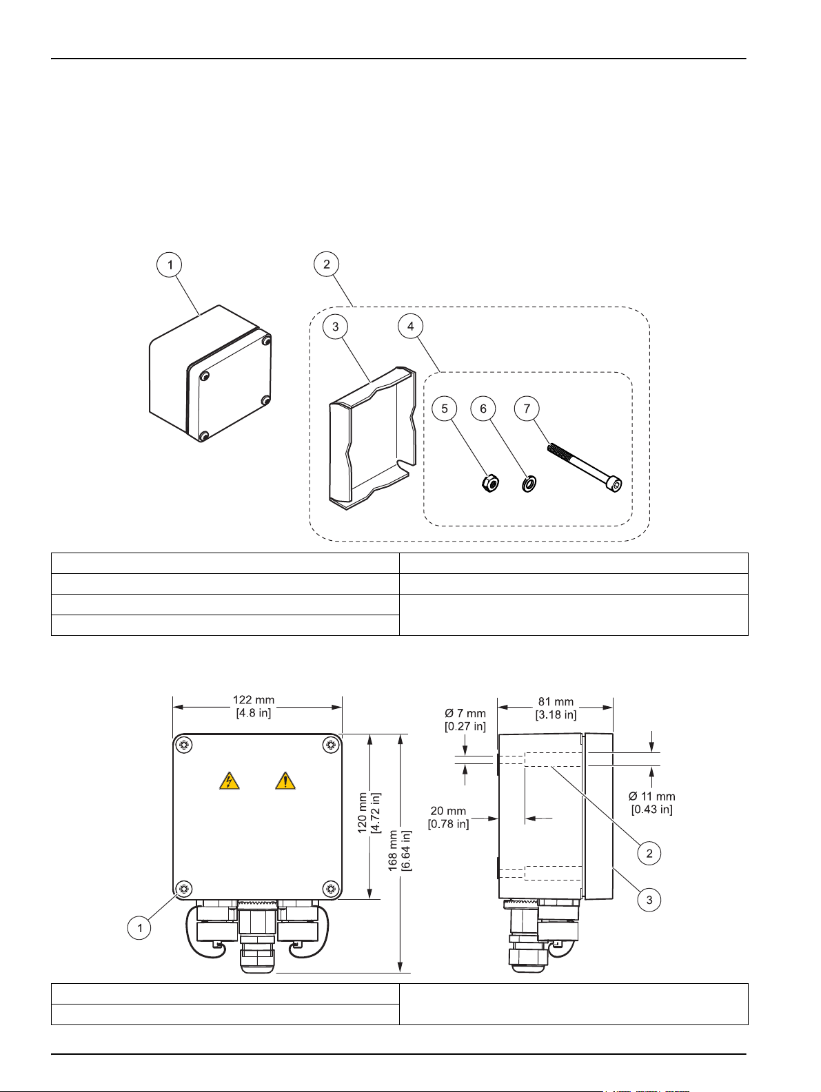
Figure 1 Parts included in the scope of delivery for the power connection box (LQV155.99.0000x)
1 Power connection box 5 Nut, M6 (4x) (LZQ058)
2 Assembly kit for the rail or pole assembly (LZQ059) 6 Washer for M6 (4x) (LZQ058)
3 Clamping plate for LZQ060 (LZQ059) 7 Hexagons socket screw, M6 x 100 mm (4x) (LZQ058)
4 Screw set for LZQ058 (LZQ059)
Figure 2 Dimensions
1 Lid screw (4x) 3 Lid
2 Screw hole (4x)
4
Page 5
Assembly
Risk of electric shock.
This device may only be connected to a single-phase power supply at 100–240 V~, which is
protected with a 15 A fuse or a current breaker.
Risk of electric shock.
The wire connection of the power supply must always contain a 2-pin disconnect switch available
on site. The disconnect switch must meet the applicable regulations. This disconnect switch must
be installed in the immediate vicinity of the device and be easily accessible; it must also be
labeled as a disconnect switch. Before opening the power supply cover, disconnect the system
electrically via the disconnect switch.
Installation location
The power connection box can be installed on a wall, a vertical pole or on horizontal rails.
During the installation of the power connection box, read the user manuals for the sensor and for
the controller. Pay particular attention to all safety instructions and danger notes.
DANGER
DANGER
NOTICE
Leave sufficient space underneath the power connection box (i.e. 50–100 mm) for cables and
connectors.
Note: Always make sure that all parts of the system can be accessed without hindrances when the
installation location is selected.
Wall assembly
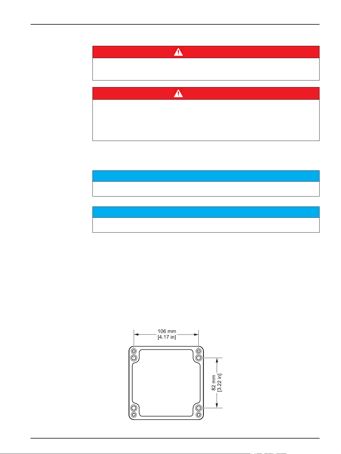
1. Loosen the four lid screws and remove the lid (refer to Figure 2, page 4).
2. Secure the housing with the four screws provided to the wall (refer to Figure 1,
page 4 and Figure 2, page 4). The dimensions required for assembly can be found in
Figure 3, page 5.
Figure 3 Dimensions
NOTICE
5
Page 6

Rail or pole assembly
Note: Make sure that the diameter of the rail or of the pole is between 35 and 55 mm.
Note: Instructions on how to secure the housing with the clamping plate can be found in Figure 4,
page 6 or Figure 5, page 6.
Figure 4 Assembly on a horizontal rail
1 Washer for M6 4 Rail
2 Nut 5 Power connection box
3 Clamping plate 6 Hexagon socket screw, M6 x 100 mm
Figure 5 Pole assembly
1 Washer for M6 4 Rail
2 Nut 5 Power connection box
3 Clamping plate 6 Hexagon socket screw, M6 x 100 mm
6
Page 7

Electrical connections
Risk of electric shock. For installation in wet areas or areas in which wetness can occur, a
residual-current circuit breaker must always be installed with this socket. For assembly in outdoor
areas, overvoltage protection is required. For fixed wire connections (cable conduit), a clearly
labeled 2-pin disconnect switch must be installed on site next to the socket, in accordance with
the applicable regulations. For the wire connection to the on-site disconnect switch, disconnect
the power supply to the socket.
With fixed wiring, a disconnecting device (local interruption) must be integrated into the supply
line. The disconnecting device must meet the applicable standards and regulations. It must be
installed near the device, be able to be reached easily by the operator and labeled as a
disconnecting device.
If the connection is established using a mains connection cable that is permanently connected to
the power supply, the plug of the mains connection cable can serve as local interruption.
Electrical dangers and fire hazards. Use only the supplied power cable.
Only qualified experts may perform the tasks described in this section of the manual, while
adhering to all locally valid safety regulations.
DANGER
DANGER
WARNING
NOTICE
Use only earthed sockets for the connection of this device to the power supply.
If you are not sure if the sockets are earthed, have this checked by a qualified electrician.
The power plug serves in addition to the power supply to isolate the device quickly from the
mains where necessary.
This is recommended for long-term storage and can prevent potential dangers in the event of a
fault.
Therefore make sure that the sockets to which the device is connected are easy to reach by each
user at all times.
DANGER
The products of the manufacturer for use outdoors have a comprehensive protection against the
penetration of moisture and dust. If these products are connected to a mains socket of the main
power line via a cable with plug instead of fixed-installation wire connections, the plug and socket
are considerably more susceptible to the penetration of moisture and dust.
It lies in the responsibility of the operator to protect plug and socket in a way that the connection
has an adequate protection against the penetration of moisture and dust and fulfils the local
safety conditions.
When the device is used outdoors, it should be connected only via a suitable socket that has at
least protection rating IP44 (protection against spray water from all directions).
The power connection box is available with and without a pre-assembled power cable. If
no pre-assembled power cable is provided, the power connection box can be connected
to the mains power via a fixed wire connection or a power cable with suitable strain relief.
The wire connection is established via the same connection terminals for a fixed wire
connection and a cable wire connection.
For the wire connection, proceed as follows (refer to Figure 6, page 9):
1. Make sure that the housing is well secured.
2. Remove the four screws and the socket lid (component 8).
7
Page 8

3. Unscrew the nut of the strain relief (component 5).
4. Remove the cap of the strain relief (component 4).
5. Strip off the insulation of all three conductors of the power cable (phase, neutral
conductor and earth conductor) over a length of 8 mm. The connection terminals are
designed for solid or stranded conductors (18 – 16 AWG).
6. Feed the cables through the strain relief or cable guide. If strain relief is used, feed
the power cable through the strain relief nut (component 5), the cap (component 4)
and the cable gland (component 3).
7. If strain relief is used, insert the cap (component 4) into the cable gland (component
3) and screw the nut (component 5) onto the cable gland. Do not tighten the nut.
NOTICE
Leave the bridges between the terminals 1 and 2 as well as 3 and 4. Both the conductors of the
power cable and the bridges must be connected to the corresponding terminals.
8. Open the fuse holder of terminal 1 — to do this, push the fuse holder down (refer to
Figure 7, page 9).
9. Connect the phase to terminal 1 (refer to Figure 8, page 10) and tighten the screw.
10. Insert the fuse holder again.
11. Open the fuse holder of terminal 4.
12. Connect the neutral conductor to terminal 4 and tighten the screw.
13. Insert the fuse holder again.
DANGER
Risk of electric shock.
A good ground connection to this product is required to make sure that this and all other
connected devices fulfill the safety standards and safety provisions.
NOTICE
The terminal block for the ground connection has several terminals. The outer screws (top and
bottom screw) are intended for the front terminals.
14. Connect the front ground cable to terminal 5 and tighten the top screw.
15. For wire connections with a power cable, tighten the nut of the cable gland
(component 3 in Figure 6, page 9), so that the cable sits firmly in the strain relief. Do
not tighten the inner conductors of the power cable too tightly under tension (instead
leave a small loop for service work).
16. Position the socket lid again and tighten the four screws.
8
Page 9

Figure 6 Cable connections
1 Cable guide 6 Power socket
2 Sealing ring
3 Cable gland Observe the output voltage at the power sockets.
The output voltage supplied by the power connection box to
the power sockets corresponds to the country-specific mains
voltage to which the power connection box is connected.
Never connect consumers with a lower input voltage to the
power connection box, if the power connection box is
operated at a higher mains voltage.
4 Cap 7 Lid
5 Nut 8 Power connection box
Note
Figure 7 Fuse holder
1 Fuse 2 Fuse holder
9
Page 10

Figure 8 Circuit diagram (see inside of the lid)
1 Phase, line (live) 7 Black for left power socket
2 Connection to terminal 1 via bridge 8 Black for right power socket
3 Connection to terminal 4 via bridge 9 White for left power socket
4 Neutral conductor 10 White for right power socket
5 Protective ground (two terminals) 11 Fuse, T 5 A H, 250 V (4x)
6 Protective ground for left and right power socket 12 Lid protective ground
Clean the power connection socket
Risk of electric shock.
Disconnect the power connection socket from the power supply before it is cleaned in order to
avoid electric shocks.
Wipe the outside of the housing with a damp cloth. Make sure that the connector is well
sealed with the sealing cap. Use a mild cleaning agent if required. Solvents must not be
used.
Replace the fuse
Risk of electric shock.
The procedures described in this section of the instruction sheet may only be performed by
qualified personnel.
Risk of electric shock.
An incorrect fuse can lead to injuries and damage. The fuse must always be replaced with a fuse
of the same type and with the same nominal values.
DANGER
DANGER
DANGER
10
1. Make sure that the power connection box is disconnected from the power supply.
Page 11

2. Loosen the screws and remove the lid.
3. Open the fuse holder (there are two fuses for each analyzer connection: one for the
phase and another for the neutral conductor — refer to Figure 7, page 9) and replace
damaged fuses with fuses of the same type and with the same nominal values (T
5 A, time-lag, H, 250 V). Close the fuse holder (component 11, Figure 8, page 10).
4. Position the lid again and tighten the screws.
Connect the sc analyzer
Risk of electric shock.
If a power socket (component 4 in Figure 9, page 11) is not to be used, make sure that the power
socket is well sealed with the cap (component 2 in Figure 9, page 11).
1. Remove the sealing cap from the connector.
2. Connect the analyzer to the power socket.
3. Secure the connector of the analyzer to the power socket.
4. Connect the sealing caps of the connector (component 1) and of the power socket
(component 2) securely together.
Figure 9 Connections of the analyzer
DANGER
1 Sealing cap for the analyzer connector 3 Analyzer connector
2 Sealing cap for the power socket 4 Power socket of the analyzer
11
Page 12

Technical data
Subject to change.
General information
Power supply 100–240 V~, + 10 %–15 %; 50/60 Hz; maximum 1000 VA
Installation category II
Pollution degree II
Fuses T 5 A (time-lag) H, 250 V (4x)
Dimensions
Weight 1250 g
Housing protection rating IP56 (with protective caps or connectors assembled)
Certifications CE, cTUVus
(H x W x T) housing: 168 mm x 122 mm x 80 mm
Assembled: (free space for the cables) x width x (free space for the hardware)
Assembly
Cable gland
Environmental conditions
Ambient temperature –20 °C to +45 °C, 95 % relative humidity, non-condensing
Materials
Enclosure Aluminum with powder coating
Wall, pole or rail (with supplied assembly kit LZQ059):
Ø 35 mm–55 mm
Strain relief: water resistant, 8–13 mm
Cable guide: 1,3 cm (0,5 inches)
Conductors: maximum 1,5 mm2 (AWG 16)
Replacement parts and accessories
Description Quantity Catalog number
Clamping plate 1LZQ060
Cable guide 1 LZX981
Fuse set (4x, T 5 H/250 V) 1 LZY460
Assembly kit for rail or pole assembly 1LZQ059
Screws set 1 LZY058
12
Page 13

Warranty and liability
The manufacturer warrants that the product supplied is free of material and manufacturing
defects and undertakes the obligation to repair or replace any defective parts at zero cost.
The warranty period for instruments is 24 months. If a service contract is taken out within
6 months of purchase, the warranty period is extended to 60 months.
With the exclusion of the further claims, the supplier is liable for defects including the lack
of assured properties as follows: all those parts that, within the warranty period calculated
from the day of the transfer of risk, can be demonstrated to have become unusable or that
can only be used with significant limitations due to a situation present prior to the transfer
of risk, in particular due to incorrect design, poor materials or inadequate finish will be
improved or replaced, at the supplier's discretion. The identification of such defects must
be notified to the supplier in writing without delay, however at the latest 7 days after the
identification of the fault. If the customer fails to notify the supplier, the product is
considered approved despite the defect. Further liability for any direct or indirect damages
is not accepted.
If instrument-specific maintenance and servicing work defined by the supplier is to be
performed within the warranty period by the customer (maintenance) or by the supplier
(servicing) and these requirements are not met, claims for damages due to the failure to
comply with the requirements are rendered void.
Any further claims, in particular claims for consequential damages cannot be made.
Consumables and damage caused by improper handling, poor installation or incorrect use
are excluded from this clause.
The manufacturer process instruments are of proven reliability in many applications and
are therefore often used in automatic control loops to provide the most economical
possible operation of the related process.
To avoid or limit consequential damage, it is therefore recommended to design the control
loop such that a malfunction in an instrument results in an automatic change over to the
backup control system; this is the safest operating state for the environment and the
process.
13
Page 14

Contact Information
HACH Company
World Headquarters
P.O. Box 389
Loveland, Colorado
80539-0389 U.S.A.
Tel (800) 227-HACH
(800) -227-4224
(U.S.A. only)
Fax (970) 669-2932
orders@hach.com
www.hach.com
HACH LANGE GMBH
Willstätterstraße 11
D-40549 Düsseldorf
Tel. +49 (0)2 11 52 88-320
Fax +49 (0)2 11 52 88-210
info@hach-lange.de
www.hach-lange.de
HACH LANGE GMBH
Rorschacherstrasse 30a
CH-9424 Rheineck
Tel. +41 (0)848 55 66 99
Fax +41 (0)71 886 91 66
info@hach-lange.ch
www.hach-lange.ch
HACH LANGE APS
Åkandevej 21
DK-2700 Brønshøj
Tel. +45 36 77 29 11
Fax +45 36 77 49 11
info@hach-lange.dk
www.hach-lange.dk
HACH LANGE LDA
Av. do Forte nº8
Fracção M
P-2790-072 Carnaxide
Tel. +351 214 253 420
Fax +351 214 253 429
info@hach-lange.pt
www.hach-lange.pt
Repair Service in the
United States:
HACH Company
Ames Service
100 Dayton Avenue
Ames, Iowa 50010
Tel (800) 227-4224
(U.S.A. only)
Fax (515) 232-3835
HACH LANGE LTD
Pacific Way
Salford
GB-Manchester, M50 1DL
Tel. +44 (0)161 872 14 87
Fax +44 (0)161 848 73 24
info@hach-lange.co.uk
www.hach-lange.co.uk
HACH LANGE FRANCE S.A.S.
8, mail Barthélémy Thimonnier
Lognes
F-77437 Marne-La-Vallée cedex 2
Tél. +33 (0) 820 20 14 14
Fax +33 (0)1 69 67 34 99
info@hach-lange.fr
www.hach-lange.fr
HACH LANGE AB
Vinthundsvägen 159A
SE-128 62 Sköndal
Tel. +46 (0)8 7 98 05 00
Fax +46 (0)8 7 98 05 30
info@hach-lange.se
www.hach-lange.se
HACH LANGE SP. ZO.O.
ul. Krakowska 119
PL-50-428 Wrocław
Tel. +48 801 022 442
Zamówienia: +48 717 177 707
Doradztwo: +48 717 177 777
Fax +48 717 177 778
info@hach-lange.pl
www.hach-lange.pl
Repair Service in Canada:
Hach Sales & Service
Canada Ltd.
1313 Border Street, Unit 34
Winnipeg, Manitoba
R3H 0X4
Tel (800) 665-7635
(Canada only)
Tel (204) 632-5598
Fax (204) 694-5134
canada@hach.com
HACH LANGE LTD
Unit 1, Chestnut Road
Western Industrial Estate
IRL-Dublin 12
Tel. +353(0)1 460 2522
Fax +353(0)1 450 9337
info@hach-lange.ie
www.hach-lange.ie
HACH LANGE NV/SA
Motstraat 54
B-2800 Mechelen
Tel. +32 (0)15 42 35 00
Fax +32 (0)15 41 61 20
info@hach-lange.be
www.hach-lange.be
HACH LANGE S.R.L.
Via Rossini, 1/A
I-20020 Lainate (MI)
Tel. +39 02 93 575 400
Fax +39 02 93 575 401
info@hach-lange.it
www.hach-lange.it
HACH LANGE S.R.O.
Zastrčená 1278/8
CZ-141 00 Praha 4 - Chodov
Tel. +420 272 12 45 45
Fax +420 272 12 45 46
info@hach-lange.cz
www.hach-lange.cz
Repair Service in
Latin America, the Caribbean,
the Far East, Indian
Subcontinent, Africa, Europe, or
the Middle East:
Hach Company World
Headquarters,
P.O. Box 389
Loveland, Colorado,
80539-0389 U.S.A.
Tel +001 (970) 669-3050
Fax +001 (970) 669-2932
intl@hach.com
HACH LANGE GMBH
Hütteldorfer Str. 299/Top 6
A-1140 Wien
Tel. +43 (0)1 912 16 92
Fax +43 (0)1 912 16 92-99
info@hach-lange.at
www.hach-lange.at
DR. LANGE NEDERLAND B.V.
Laan van Westroijen 2a
NL-4003 AZ Tiel
Tel. +31(0)344 63 11 30
Fax +31(0)344 63 11 50
info@hach-lange.nl
www.hach-lange.nl
HACH LANGE SPAIN S.L.U.
Edificio Seminario
C/Larrauri, 1C- 2ª Pl.
E-48160 Derio/Bizkaia
Tel. +34 94 657 33 88
Fax +34 94 657 33 97
info@hach-lange.es
www.hach-lange.es
HACH LANGE S.R.O.
Roľnícka 21
SK-831 07 Bratislava – Vajnory
Tel. +421 (0)2 4820 9091
Fax +421 (0)2 4820 9093
info@hach-lange.sk
www.hach-lange.sk
HACH LANGE KFT.
Vöröskereszt utca. 8-10.
H-1222 Budapest XXII. ker.
Tel. +36 1 225 7783
Fax +36 1 225 7784
info@hach-lange.hu
www.hach-lange.hu
HACH LANGE D.O.O.
Fajfarjeva 15
SI-1230 Domžale
Tel. +386 (0)59 051 000
Fax +386 (0)59 051 010
info@hach-lange.si
www.hach-lange.si
HACH LANGE OOO
Finlyandsky prospekt, 4A
Business Zentrum “Petrovsky
fort”, R.803
RU-194044, Sankt-Petersburg
Tel. +7 (812) 458 56 00
Fax. +7 (812) 458 56 00
info.russia@hach-lange.com
www.hach-lange.com
14
HACH LANGE S.R.L.
Str. Căminului nr. 3,
et. 1, ap. 1, Sector 2
RO-021741 Bucureşti
Tel. +40 (0) 21 205 30 03
Fax +40 (0) 21 205 30 17
info@hach-lange.ro
www.hach-lange.ro
ΗΑCH LANGE E.Π.Ε.
Αυλίδος 27
GR-115 27 Αθήνα
Τηλ . +30 210 7777038
Fax +30 210 7777976
info@hach-lange.gr
www.hach-lange.gr
HACH LANGE
8, Kr. Sarafov str.
BG-1164 Sofia
Tel. +359 (0)2 963 44 54
Fax +359 (0)2 866 15 26
info@hach-lange.bg
www.hach-lange.bg
HACH LANGE D.O.O.
Ivana Severa bb
HR-42 000 Varaždin
Tel. +385 (0) 42 305 086
Fax +385 (0) 42 305 087
info@hach-lange.hr
www.hach-lange.hr
HACH LANGE SU
ANALİZ SİSTEMLERİ LTD . ŞTİ.
Ilkbahar mah. Galip Erdem Cad.
616 Sok. No:9
TR-Oran-Çankaya/ANKARA
Tel. +90312 490 83 00
Fax +90312 491 99 03
bilgi@hach-lange.com.tr
www.hach-lange.com.tr
HACH LANGE MAROC SARLAU
Villa 14 – Rue 2 Casa Plaisance
Quartier Racine Extension
MA-Casablanca 20000
Tél. +212 (0)522 97 95 75
Fax +212 (0)522 36 89 34
info-maroc@hach-lange.com
www.hach-lange.ma
 Loading...