

Page 1
DOC023.52.93069
Polymetron 9586 Oxygen
Scavenger Analyzer
11/2013, Edition 3
User Manual
Page 2

Page 3

Table of Contents
Additional information.............................................................................................3
Specifications..............................................................................................................3
General information..................................................................................................4
Safety information........................................................................................................4
Use of hazard information....................................................................................5
Precautionary labels ............................................................................................5
EMC compliance statement (Korea)..................................................................... 6
Certification........................................................................................................... 6
Product components....................................................................................................6
Product overview.........................................................................................................7
Installation.....................................................................................................................7
Analyzer mounting.......................................................................................................8
Wiring overview...........................................................................................................9
High-voltage barrier..............................................................................................9
Wiring for power...................................................................................................9
Alarms and relays...............................................................................................12
Wiring relays.......................................................................................................12
Analog output connections.................................................................................14
Discrete input wiring connections.......................................................................15
Connect the optional digital communication output............................................17
Install a Secure Digital (SD) memory card ........................................................17
Plumb the sample and drain lines.............................................................................. 17
Install the reagents....................................................................................................18
Startup........................................................................................................................... 18
User interface and navigation............................................................................18
User interface............................................................................................................18
Display.......................................................................................................................19
Additional display formats................................................................................... 20
Graphical display................................................................................................20
System startup..........................................................................................................21
Set the language, date and time for the first time .....................................................21
Controller configuration information...........................................................................21
Using the secure digital memory (SD) card...............................................................23
Updating software............................................................................................... 23
Save data and event logs with SD cards............................................................23
Access data and event log files on the SD card.................................................24
Firmware updates with SD cards........................................................................ 25
Backup settings to an SD card...........................................................................25
Restore settings to the controller........................................................................25
Transfer settings to another device....................................................................25
Operation.....................................................................................................................26
Configure the sensor.................................................................................................26
Calibration.................................................................................................................. 26
About sensor calibration.....................................................................................26
1
Page 4

Table of Contents
Temperature calibration...................................................................................... 26
Zero calibration...................................................................................................27
Calibration with the process sample...................................................................27
Exit calibration procedure...................................................................................28
Change calibration options.................................................................................28
Reset calibration options....................................................................................29
Maintenance...............................................................................................................29
Cleaning and decontamination..................................................................................29
Fuse replacement......................................................................................................29
Battery replacement................................................................................................... 29
Troubleshooting.......................................................................................................29
General troubleshooting............................................................................................29
Test and maintenance menu.....................................................................................31
Sensor diagnostic and test menu..............................................................................32
Warning and error conditions..................................................................................... 33
Warning list.........................................................................................................33
Error list..............................................................................................................34
Replacement parts and accessories...............................................................34
Material safety data sheets (MSDS).................................................................35
MSDS - Diisopropylamine.......................................................................................... 35
2
Page 5
Additional information
Additional information is available on the manufacturer's website.
Specifications
Specifications are subject to change without notice.
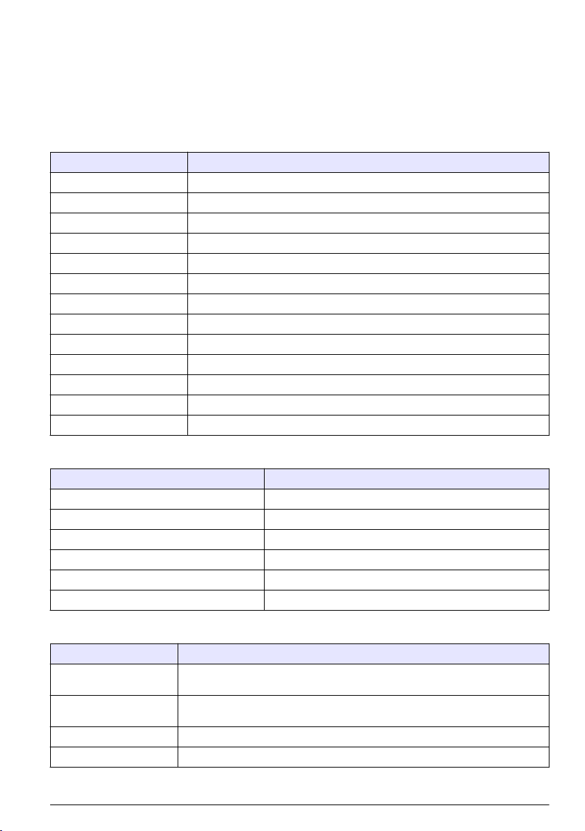
Panel
Specification Details
Dimensions 817 x 300 x 140 mm (32.2 x 11.8 x 5.5 in)
Weight 14.6 kg (32.15 lbs)
Sample flow rate 10—15 liters/hour
Working pressure 0.5—6 bar (7—87 psi)
Ambient temperature 0—60 °C (-32—140 °F)
Relative humidity 10—90%
Working electrode Platinum
Counter electrode Stainless steel
Reference Ag / AgCl / KCl 0.1 M
Measuring cell Acrylic
Sample conditioner DIPA (diisopropylamine)
European standards EN 61326 Class A for EMC; EN 601010-1 for low voltage safety
International standards cETLus
Sensor
Specification Details
Measuring range 0—500 ppb hydrazine; 0—100 ppb carbohydrazide
Sensitivity < 0.2 ppb
Repeatability 1 ppb or ± 2% of measurement whichever is the greater
Detection limit ≤ 1 ppb
Response time < 60 seconds
Sample temperature measurement range 5—45 °C (41—113 °F)
Controller
Specification Details
Component description Microprocessor-controlled and menu-driven controller that operates the sensor and
Operating temperature -20 to 60 ºC (-4 to 140 ºF); 95% relative humidity, non-condensing with sensor load
Storage temperature -20 to 70 ºC (-4 to 158 ºF); 95% relative humidity, non-condensing
Enclosure
1
displays measured values.
<7 W; -20 to 50 ºC (-4 to 104 ºF) with sensor load <28 W
NEMA 4X/IP66 metal enclosure with a corrosion-resistant finish
English 3
Page 6
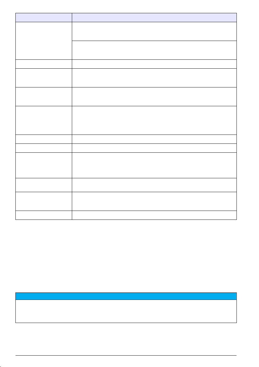
Specification Details
Power requirements AC powered controller: 100-240 VAC ±10%, 50/60 Hz; Power 50 VA with 7 W
Altitude requirements Standard 2000 m (6562 ft) ASL (Above Sea Level)
Pollution
degree/Installation
category
Outputs Two analog (0-20 mA or 4-20 mA) outputs. Each analog output can be assigned to
Relays Four SPDT, user-configured contacts, rated 250 VAC, 5 Amp resistive maximum for
Dimensions ½ DIN—144 x 144 x 180.9 mm (5.7 x 5.7 x 7.12 in.)
Weight 1.7 kg (3.75 lb)
Compliance information2CE approved (with all sensor types). Listed for use in general locations to UL and
Digital communication Optional Modbus, RS232/RS485, Profibus DPV1 or HART network connection for
Data logging Secure Digital Card (32 GB maximum) or special RS232 cable connector for data
Warranty 2 years
1
Units that have the Underwriters Laboratories (UL) certification are intended for indoor use only and do not
have a NEMA 4X/IP66 rating.
2
DC powered units are not listed by UL.
sensor/network module load, 100 VA with 28 W sensor/network module load
(optional Modbus, RS232/RS485, Profibus DPV1 or HART network connection).
24 VDC powered controller: 24 VDC—15%, + 20%; Power 15 W with 7 W
sensor/network module load, 40 W with 28 W sensor/network module load (optional
Modbus, RS232/RS485, Profibus DPV1 or HART network connection).
Polution Degree 2; Installation Category II
represent a measured parameter such as pH, temperature, flow or calculated
values. Optional module supplies three additional analog outputs (5 total).
the AC powered controller and 24 VDC, 5A resistive maximum for the DC powered
controller. Relays are designed for connection to AC Mains circuits (i.e., whenever
the controller is operated with 115 - 240 VAC power) or DC circuits (i.e., whenever
the controller is operated with 24 VDC power).
CSA safety standards by ETL (with all sensor types).
Certain AC mains powered models are listed for use in general safety locations to
UL and CSA safety standards by Underwriters Laboratories (with all sensor types).
data transmission
logging and performing software updates. The controller will keep approximately
20,000 data points per sensor.
General information
In no event will the manufacturer be liable for direct, indirect, special, incidental or consequential
damages resulting from any defect or omission in this manual. The manufacturer reserves the right to
make changes in this manual and the products it describes at any time, without notice or obligation.
Revised editions are found on the manufacturer’s website.
Safety information
N O T I C E
The manufacturer is not responsible for any damages due to misapplication or misuse of this product including,
without limitation, direct, incidental and consequential damages, and disclaims such damages to the full extent
permitted under applicable law. The user is solely responsible to identify critical application risks and install
appropriate mechanisms to protect processes during a possible equipment malfunction.
Please read this entire manual before unpacking, setting up or operating this equipment. Pay
attention to all danger and caution statements. Failure to do so could result in serious injury to the
operator or damage to the equipment.
4
English
Page 7
Make sure that the protection provided by this equipment is not impaired. Do not use or install this
equipment in any manner other than that specified in this manual.
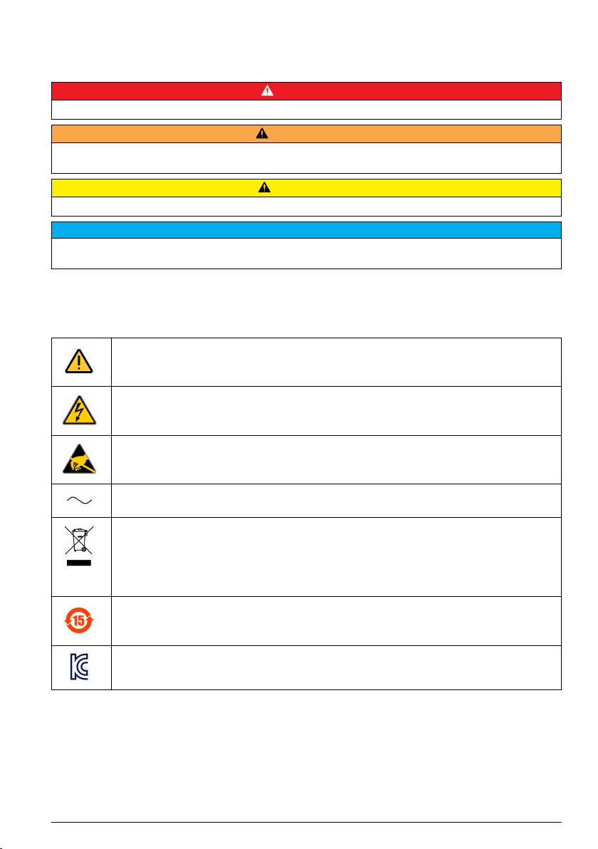
Use of hazard information
D A N G E R
Indicates a potentially or imminently hazardous situation which, if not avoided, will result in death or serious injury.
Indicates a potentially or imminently hazardous situation which, if not avoided, could result in death or serious
injury.
Indicates a potentially hazardous situation that may result in minor or moderate injury.
Indicates a situation which, if not avoided, may cause damage to the instrument. Information that requires special
emphasis.
W A R N I N G
C A U T I O N
N O T I C E
Precautionary labels
Read all labels and tags attached to the product. Personal injury or damage to the product could
occur if not observed. A symbol on the instrument is referenced in the manual with a precautionary
statement.
This symbol, when noted on a product, indicates a potential hazard which could cause serious
personal injury and/or death. The user should reference this instruction manual for operation and/or
safety information.
This symbol, when noted on a product enclosure or barrier, indicates that a risk of electrical shock
and/or electrocution exists and indicates that only individuals qualified to work with hazardous
voltages should open the enclosure or remove the barrier.
This symbol, when noted on the product, indicates the presence of devices sensitive to electrostatic
discharge and indicates that care must be taken to prevent damage to them.
This symbol, when noted on a product, indicates the instrument is connected to alternate current.
Electrical equipment marked with this symbol may not be disposed of in European public disposal
systems. In conformity with European local and national regulations, European electrical equipment
users must now return old or end-of-life equipment to the manufacturer for disposal at no charge to
the user.
Note: For return for recycling, please contact the equipment producer or supplier for instructions on how to return
end-of-life equipment, producer-supplied electrical accessories, and all auxiliary items for proper disposal.
Products marked with this symbol indicates that the product contains toxic or hazardous substances
or elements. The number inside the symbol indicates the environmental protection use period in
years.
Products marked with this symbol indicates that the product conforms to relevant South Korean
EMC standards.
English 5
Page 8

EMC compliance statement (Korea)
Type of equipment Additional information
A 급 기기
( 업무용 방송통신기자재 )
Class A equipment
(Industrial Broadcasting and Communication
Equipment)
이 기기는 업무용 (A 급 ) 전자파적합기기로서 판매자 또
는 사용자는 이 점을 주의하시기 바라며, 가정외의 지역
에서 사용하는 것을 목적으로 합니다.
This equipment meets Industrial (Class A) EMC
requirements. This equipment is for use in industrial
environments only.
Certification
Canadian Radio Interference-Causing Equipment Regulation, IECS-003, Class A:
Supporting test records reside with the manufacturer.
This Class A digital apparatus meets all requirements of the Canadian Interference-Causing
Equipment Regulations.
FCC Part 15, Class "A" Limits
Supporting test records reside with the manufacturer. The device complies with Part 15 of the FCC
Rules. Operation is subject to the following conditions:
1. The equipment may not cause harmful interference.
2. The equipment must accept any interference received, including interference that may cause
undesired operation.
Changes or modifications to this equipment not expressly approved by the party responsible for
compliance could void the user's authority to operate the equipment. This equipment has been tested
and found to comply with the limits for a Class A digital device, pursuant to Part 15 of the FCC rules.
These limits are designed to provide reasonable protection against harmful interference when the
equipment is operated in a commercial environment. This equipment generates, uses and can
radiate radio frequency energy and, if not installed and used in accordance with the instruction
manual, may cause harmful interference to radio communications. Operation of this equipment in a
residential area is likely to cause harmful interference, in which case the user will be required to
correct the interference at their expense. The following techniques can be used to reduce
interference problems:
1. Disconnect the equipment from its power source to verify that it is or is not the source of the
interference.
2. If the equipment is connected to the same outlet as the device experiencing interference, connect
the equipment to a different outlet.
3. Move the equipment away from the device receiving the interference.
4. Reposition the receiving antenna for the device receiving the interference.
5. Try combinations of the above.
Product components
Make sure that all components have been received. If any items are missing or damaged, contact the
manufacturer or a sales representative immediately.
6
English
Page 9
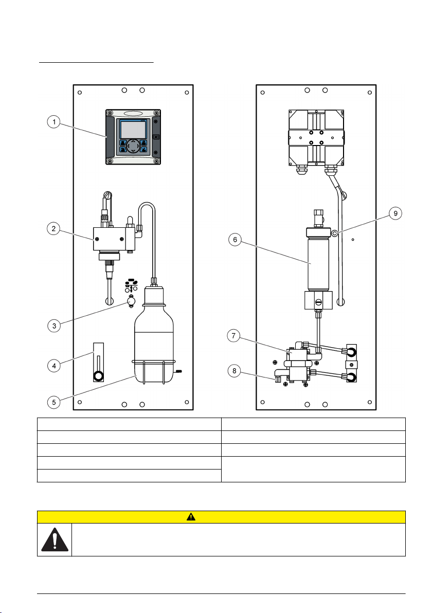
Product overview
The analyzer is designed to continuously measure the amount of oxygen scavengers (hydrazine or
carbohydrazide) in water.
Figure 1 Front and rear view
1 Controller 6 Chemical zero cartridge (option)
2 Measuring cell 7 Pressure regulator
3 Chemical zero on/off (option) 8 Sample in, 4/6 mm tube
4 Flow meter 9 Sample drain, 6/8 mm tube, atmospheric pressure
5 Sample conditioning bottle (DIPA)
Installation
C A U T I O N
Multiple hazards. Only qualified personnel must conduct the tasks described in this section of the
document.
English 7
Page 10
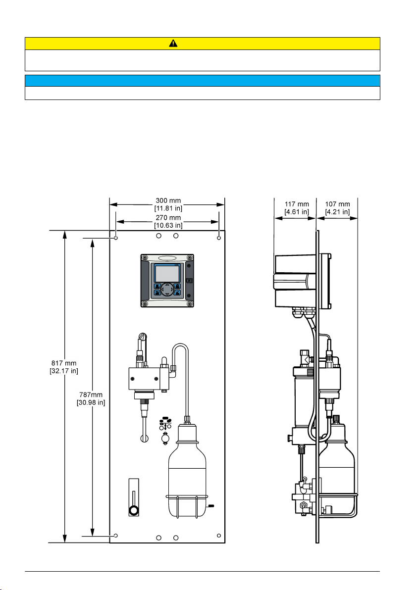
Analyzer mounting
C A U T I O N
Personal injury hazard. Instruments or components are heavy. Use assistance to install or move. Make sure that
the wall mounting is able to hold 4 times the weight of the equipment.
The analyzer must be aligned vertically to guarantee accuracy.
Attach the analyzer to a stable, vertical surface. Use a level to make sure that the analyzer is
completely vertical. Refer to the guidelines that follow.
• Put the instrument in a location that has access for operation, service and calibration.
• Make sure that there is good view of the display and controls.
• Keep the instrument away from a heat source.
• Keep the instrument away from vibrations.
• Keep the sample tubing as short as possible to minimize the response time.
• Make sure that there is no air in the sample supply line.
N O T I C E
8 English
Page 11
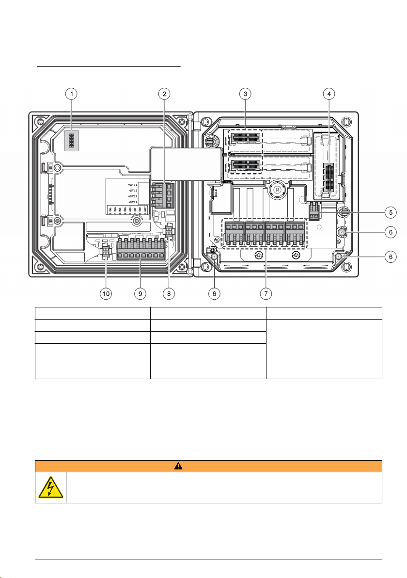
Wiring overview
Figure 2 shows an overview of the wiring connections inside the controller with the high voltage
barrier removed. The left side of the figure shows the back side of the controller cover.
Note: Remove connector caps from the connectors before module installation.
Figure 2 Wiring connections overview
1 Service cable connection 5 AC and DC power connector
2 4-20 mA output
3 Sensor module connector 7 Relay connections
4 Communication module
connector (e.g., Modbus,
Profibus, HART, optional
4-20 mA module, etc.)
1
Terminals can be removed for improved access.
1
6 Ground terminals 10 Digital sensor connector
1
8 Digital sensor connector
1
9 Discrete input wiring connector
1
1
High-voltage barrier
High-voltage wiring for the controller is located behind the high-voltage barrier in the controller
enclosure. The barrier must remain in place except when installing modules or when a qualified
installation technician is wiring for power, alarms, outputs or relays. Do not remove the barrier while
power is applied to the controller.
Wiring for power
W A R N I N G
Potential Electrocution Hazard. Always disconnect power to the instrument when making electrical
connections.
English 9
1
Page 12
W A R N I N G
Potential Electrocution Hazard. If this equipment is used outdoors or in potentially wet locations, a
Ground Fault Interrupt device must be used for connecting the equipment to its mains power source.
D A N G E R
Electrocution Hazard. Do not connect AC power to a 24 VDC powered model.
W A R N I N G
Potential Electrocution Hazard. A protective earth (PE) ground connection is required for both
100-240 VAC and 24 VDC wiring applications. Failure to connect a good PE ground connection can
result in shock hazards and poor performance due to electromagnetic interferences. ALWAYS connect
a good PE ground to the controller terminal.
Install the device in a location and position that gives easy access to the disconnect device and its operation.
N O T I C E
The controller can be purchased as either a 100-240 VAC powered model or a 24 VDC powered
model. Follow the appropriate wiring instructions for the purchased model.
The controller can be wired for line power by hard-wiring in conduit or wiring to a power cord.
Regardless of the wire used, the connections are made at the same terminals. A local disconnect
designed to meet local electrical code is required and must be identified for all types of installation. In
hard-wired applications, the power and safety ground service drops for the instrument must be 18 to
12 AWG.
Notes:
• The voltage barrier must be removed before making any electrical connections. After making all
connections, replace the voltage barrier before closing the controller cover.
• A sealing type strain relief and a power cord less than 3 meters (10 feet) in length with three 18-
gauge conductors (including a safety ground wire) can be used to maintain the NEMA
4X/IP66 environmental rating.
• Controllers can be ordered with AC power cords pre-installed. Additional power cords may also be
ordered.
• The DC power source that supplies power to the 24 VDC powered controller must maintain
voltage regulation within the specified 24 VDC-15% +20% voltage limits. The DC power source
must also provide adequate protection against surges and line transients.
Wiring procedure
Refer to the illustrated steps that follow and Table 1 or Table 2 to wire the controller for power. Insert
each wire into the appropriate terminal until the insulation is seated against the connector with no
bare wire exposed. Tug gently after insertion to make sure that there is a secure connection. Seal
any unused openings in the controller box with conduit opening sealing plugs.
Table 1 AC power wiring information (AC powered models only)
Terminal Description Color—North America Color—EU
1 Hot (L1) Black Brown
2 Neutral (N) White Blue
— Protective Earth (PE) Ground lug Green Green with yellow stripe
10 English
Page 13
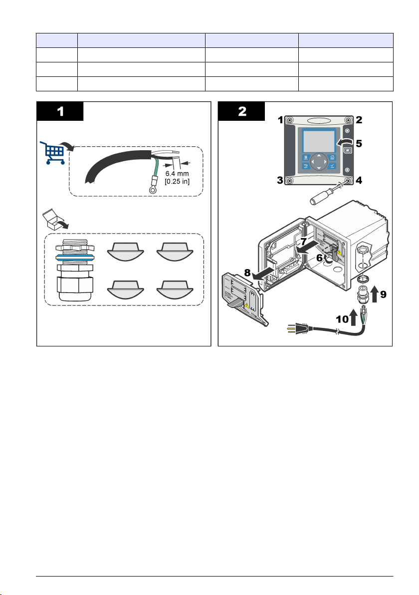
Table 2 DC power wiring information (DC powered models only)
Terminal Description Color—North America Color—EU
1 +24 VDC Red Red
2 24 VDC return Black Black
— Protective Earth (PE) Ground lug Green Green with yellow stripe
English 11
Page 14

Alarms and relays
The controller is equipped with four unpowered, single pole relays rated 100-250 VAC, 50/60 Hz,
5 amp resistive maximum. Contacts are rated 250 VAC, 5 amp resistive maximum for the AC
powered controller and 24 VDC, 5A resistive maximum for the DC powered controller. The relays are
not rated for inductive loads.
Wiring relays
W A R N I N G
Potential Electrocution Hazard. Always disconnect power to the instrument when making electrical
connections.
W A R N I N G
Potential fire hazard. The relay contacts are rated 5A and are not fused. External loads connected to
the relays must have current limiting devices provided to limit current to < 5 A.
W A R N I N G
Potential fire hazard. Do not daisy-chain the common relay connections or jumper wire from the mains
power connection inside the instrument.
W A R N I N G
Potential electrocution hazard. In order to maintain the NEMA/IP environmental ratings of the
enclosure, use only conduit fittings and cable glands rated for at least NEMA 4X/IP66 to route cables in
to the instrument.
AC line (100—250 V) powered controllers
12
English
Page 15

W A R N I N G
Potential electrocution hazard. AC mains powered controllers (115 V–230 V) are designed for relay
connections to AC mains circuits (i.e., voltages greater than 16 V-RMS, 22.6 V-PEAK or 35 VDC).
The wiring compartment is not designed for voltage connections in excess of 250 VAC.
24 VDC powered controllers
W A R N I N G
Potential electrocution hazard. 24 V powered controllers are designed for relay connections to low
voltage circuits (i.e., voltages less than 16 V-RMS, 22.6 V-PEAK or 35 VDC).
The 24 VDC controller relays are designed for the connection to low voltage circuits (i.e., voltages
less than 30 V-RMS, 42.2 V-PEAK or 60 VDC). The wiring compartment is not designed for voltage
connections above these levels.
The relay connector accepts 18–12 AWG wire (as determined by load application). Wire gauge less
than 18 AWG is not recommended.
The Normally Open (NO) and Common (COM) relay contacts will be connected when an alarm or
other condition is active. The Normally Closed (NC) and Common relay contacts will be connected
when an alarm or other condition is inactive (unless the Fail Safe is set to Yes) or when power is
removed from the controller.
Most relay connections use either the NO and COM terminals or the NC and COM terminals. The
numbered installation steps show connection to the NO and COM terminals.
English 13
Page 16

Analog output connections
W A R N I N G
Potential Electrocution Hazard. Always disconnect power to the instrument when making electrical
connections.
W A R N I N G
Potential electrocution hazard. In order to maintain the NEMA/IP environmental ratings of the
enclosure, use only conduit fittings and cable glands rated for at least NEMA 4X/IP66 to route cables in
to the instrument.
Two isolated analog outputs (1 and 2) are provided (Figure 3). Such outputs are commonly used for
analog signaling or to control other external devices.
Make wiring connections to the controller as shown in Figure 3 and Table 3.
Note: Figure 3 shows the back of the controller cover and not the inside of the main controller compartment.
Table 3 Output connections
Recorder wires Circuit board position
Output 2– 4
Output 2+ 3
Output 1– 2
Output 1+ 1
1. Open the controller cover.
2. Feed the wires through the strain relief.
3. Adjust the wire as necessary and tighten the strain relief.
14
English
Page 17

4. Make connections with twisted-pair shielded wire and connect the shield at the controlled
component end or at the control loop end.
• Do not connect the shield at both ends of the cable.
• Use of non-shielded cable may result in radio frequency emission or susceptibility levels higher
than allowed.
• Maximum loop resistance is 500 ohm.
5. Close the controller cover and tighten the cover screws.
6. Configure outputs in the controller.
Figure 3 Analog output connections
Discrete input wiring connections
W A R N I N G
Potential Electrocution Hazard. Always disconnect power to the instrument when making electrical connections.
Potential electrocution hazard. In order to maintain the NEMA/IP environmental ratings of the enclosure, use only
conduit fittings and cable glands rated for at least NEMA 4X/IP66 to route cables in to the instrument.
Three discrete inputs are provided for switch closure inputs or logic level voltage inputs. Make wiring
connections and configure jumper settings to the controller as shown in Figure 4, Table 4 and
Figure 5.
Note: Figure 4 shows the back of the controller cover and not the inside of the main controller compartment.
W A R N I N G
English
15
Page 18

Figure 4 Discrete input wiring connections
Table 4 Input connections
Discrete inputs Connector position - Switch input Connector position - Voltage
Input 1+ 3 2
Input 1- 2 3
Input 2+ 6 5
Input 2- 5 6
Input 3+ 8 7
Input 3- 7 8
input
Figure 5 Jumper settings
1 Input 1 configuration jumpers 3 Input 3 configuration jumpers 5 Jumpers positioned to the right
2 Input 2 configuration jumpers 4 Jumpers positioned to the left for
switch inputs
for voltage inputs
1. Open the controller cover.
2. Feed the wires through the cable gland.
3. Adjust the wire as necessary and tighten the cable gland.
4. The jumpers are positioned immediately behind the connector. Remove the connector for
improved access to the jumpers and configure the jumper settings according to the type of input
as shown in Figure 5.
5. Close the controller cover and tighten the cover screws.
6. Configure inputs in the controller.
16
English
Page 19

Note: In switch input mode the controller supplies 12 volts to the switch and is not isolated from the controller. In
voltage input mode the inputs are isolated from the controller (user input voltage from 0 to 30 volts).
Connect the optional digital communication output
The manufacturer supports Modbus RS485, Modbus RS232, Profibus DPV1 and HART
communication protocols. The optional digital output module is installed in the location indicated by
item 4 in Figure 2 on page 9. Refer to the instructions supplied with the network module for more
details.
For information about Modbus registers, go to http://www.hach-lange.com or http://www.hach.com
and search Modbus registers or go to any sc200 product page.
Install a Secure Digital (SD) memory card
For instructions on how to install an SD card in the controller, refer to Figure 6. Information on how to
use the SD memory card can be found in Using the secure digital memory (SD) card on page 23.
To remove an SD card, push down on the edge of the card and release, then pull the card up and out
of the slot. After the card is removed, close the slot cover and tighten the cover screws.
Figure 6 SD card installation
Plumb the sample and drain lines
Connect the sample and drain lines to the fittings on the back of the panel.
1. Connect the sample line to the inlet 4/6-mm OD tube fitting.
2. Connect a drain line to the drain 6/8-mm OD tube fitting. Keep the drain line as short as possible
at atmospheric pressure.
English
17
Page 20

Install the reagents
W A R N I N G
Chemical exposure hazard. Obey laboratory safety procedures and wear all of the personal protective
equipment appropriate to the chemicals that are handled. Refer to the current safety data sheets
(MSDS/SDS) for safety protocols.
1. Fill the empty sample conditioning bottle with DIPA (diisopropylamine) and enter the hazardous
reagent information on the blank label attached to the bottle.
2. Install the sample conditioning bottle on the front of the analyzer.
3. Connect the supplied tube to the measuring cell. Install the tube completely into the bottle of
conditioning solution. Make sure that the tube fittings are tight to prevent leakage of fumes from
the conditioning bottle into the atmosphere.
4. If the chemical zero cartridge is used, install the cartridge on the rear of the analyzer.
Startup
Make sure that the flow rate and pressure do not exceed the values in Specifications on page 3.
1. Open the valve on the sample line to let sample flow through the analyzer.
2. Turn the knob on the flow meter to set the flow rate.
3. Examine the plumbing for leaks and stop any leaks if found.
4. Apply power to the controller.
5. Make the applicable menu selections when the controller starts.
User interface and navigation
User interface
The keypad has four menu keys and four directional keys as shown in Figure 7.
18
English
Page 21

Figure 7 Keypad and front panel overview
1 Instrument display 5 BACK key. Moves back one level in the menu
2 Cover for secure digital memory card slot 6 MENU key. Moves to the Settings Menu from other
3 HOME key. Moves to the Main Measurement
screen from other screens and submenus.
4 ENTER key. Accepts input values, updates, or
displayed menu options.
structure.
screens and submenus.
7 Directional keys. Used to navigate through the
menus, change settings, and increment or
decrement digits.
Inputs and outputs are set up and configured through the front panel using the keypad and display
screen. This user interface is used to set up and configure inputs and outputs, create log information
and calculated values, and calibrate sensors. The SD interface can be used to save logs and update
software.
Display
Figure 8 shows an example of the main measurement screen with the sensor connected to the
controller.
The front panel display screen shows sensor measurement data, calibration and configuration
settings, errors, warnings and other information.
English
19
Page 22

Figure 8 Example of Main Measurement screen
1 Home screen icon 7 Warning status bar
2 Sensor name 8 Date
3 SD Memory card icon 9 Analog output values
4 Relay status indicator 10 Time
5 Measurement value 11 Progress bar
6 Measurement unit 12 Measurement parameter
Table 5 Icon descriptions
Icon Description
Home screen The icon may vary depending on the screen or menu being displayed. For example, if an SD
SD memory
card
Warning A warning icon consists of an exclamation point within a triangle. Warning icons appear on the
Error An error icon consists of an exclamation point within a circle. When an error occurs, the error
card is installed, an SD card icon appears here when the user is in the SD Card Setup menu.
This icon appears only if an SD card is in the reader slot. When a user is in the SD Card Setup
menu, this icon appears in the upper left corner.
right of the main display below the measurement value. Push the ENTER key then select the
device to view any problems associated with that device. The warning icon will no longer be
displayed once all problems have been corrected or acknowledged.
icon and the measurement screen flash alternately in the main display. To view errors, push the
MENU key and select Diagnostics. Then select the device to view any problems associated
with that device.
Additional display formats
• From the Main Measurement screen push the UP and DOWN arrow keys to switch between
measurement parameters
• From the Main Measurement screen push the RIGHT arrow key to switch to a split display of up to
4 measurement parameters. Push the RIGHT arrow key to include additional measurements. Push
the LEFT arrow key as needed to return to the Main Measurement screen
• From the Main Measurement screen push the LEFT arrow key to switch to the graphical display
(see Graphical display on page 20 to define the parameters). Push the UP and DOWN arrow
keys to switch measurement graphs
Graphical display
The graph shows concentration and temperature measurements for each channel in use. The graph
supplies easy monitoring of trends and shows changes in the process.
20
English
Page 23

1. From the graphical display screen use the up and down arrow keys to select a graph and push
the HOME key.
2. Select an option:
Option Description
MEASUREMENT VALUE Set the measurement value for the selected channel. Select between Auto Scale
DATE & TIME RANGE Select the date and time range from the available options
and Manually Scale. For manual scaling enter the minimum and maximum
measurement values
System startup
When initially powered up, the LANGUAGE, DATE FORMAT and DATE/TIME screens appear in
order. After these options are set, the controller performs a device scan and displays the message
SCANNING FOR DEVICES. PLEASE WAIT... If a new device is found, the controller performs an
installation process before displaying a main measurement screen.
If the scan finds previously installed devices without configuration changes, the main measurement
screen of the device in the number one position appears immediately after the scan is complete.
If a device has been removed from the controller or is not found during the next power-cycled or
menu-driven scan, the controller displays a DEVICE MISSING message and prompts to delete the
missing device.
If no sensor is connected to an installed analog module, the controller will indicate an error. If devices
are connected but not found by the controller, refer to the Troubleshooting section of this manual.
Set the language, date and time for the first time
The controller displays the language, date and time edit screens when the controller is powered on
for the first time, and when it is powered on after the configuration settings have been set to their
default values.
After the language, date and time options are set for the first time, update the options as necessary
through the setup menu.
1. In the LANGUAGE screen, highlight a language in the options list and push the enter key.
English is the default language for the controller.
2. In the DATE FORMAT screen, highlight a format and push the enter key.
3. In the DATE/TIME screen, push the right or left arrow keys to highlight a field, then push the up
and down arrow keys to update the value in the field. Update the other fields as necessary.
4. Push the enter key. The changes are saved and the controller performs a start-up scan for
devices. If connected devices are found, the controller displays the main measurement screen for
the device in the number one position. If the controller fails to find connected devices, refer to the
Troubleshooting section of this manual.
Controller configuration information
General information about configuration options is listed in the table.
1. Push the menu key and select Polymetron 9500 SETUP.
Option Description
SECURITY SETUP Sets the passcode preferences.
OUTPUT SETUP Configures the controller analog outputs.
RELAY SETUP Configures the controller relays.
English 21
Page 24

Option Description
DISPLAY SETUP Configures the controller display.
ADJUST ORDER—View and modify the measurement display order.
• SEE CURRENT ORDER—View the current display order
• ADD MEASUREMENTS—Add selected measurements to the display
• REMOVE MEASUREMENTS—Remove selected measurements from the
display
• REORDER LIST—Select one or more measurements and change their order
in the display
• SEE DEFAULT ORDER—View the default display order
• SET TO DEFAULT—Set the display order to the default configuration
Note: Some of the above will not be available if no adjustment is possible for that
option (e.g. REORDER LIST and REMOVE MEASUREMENTS will not be
available if only one measurement is selected for display).
DISPLAY CONTRAST—Adjusts the contrast of the controller display.
EDIT NAME—Assigns a name to the controller.
SET DATE/TIME Sets the controller time and date.
DATALOG SETUP Configures data logging options. Available only if CALCULATION has been
MANAGE DATA Select the device from the list of installed components and then select VIEW
ERROR HOLD MODE HOLD OUTPUTS—Holds outputs at last known value when controller loses
CALCULATION Configures the controller math function.
Poly
9500 INFORMATION
DISCRETE INPUT
SETUP
LANGUAGE Assigns the language used in the controller.
setup.
DATA LOG or VIEW EVENT LOG depending on the type of log entry to view.
Specify the selection period to list all log entries matching the selection criteria.
Push the up and down arrows to select an entry and then push enter to view
more details.
communication with the sensor.
TRANSFER OUTPUTS—Switches to transfer mode when controller loses
communication with the sensor. Outputs transfer to a pre-defined value.
SET VARIABLE X—Selects the sensor for the x variable.
SET PARAMETER X—Selects the sensor measurement for the x variable.
SET VARIABLE Y—Selects the sensor for the y variable.
SET PARAMETER Y—Selects the sensor measurement for the y variable.
SET FORMULA—Select the math function to implement:
• None—Disables the math function
• X-Y—Subtraction function
• X+Y—Addition function
• X/Y—Division function
• [X/Y]%—Percentage function
• [X+Y]/2—Average function
• [X*Y]—Multiplication function
• [X-Y]%/X—Difference function
DISPLAY FORMAT—Selects the number of digits and decimal points.
SET UNITS—Selects the units for the calculated reading.
SET PARAMETER—Selects the parameter for the calculated reading.
Displays information about the controller including serial number and software
versions.
Configures three discrete input channels.
22 English
Page 25

2. Select an option and push enter to activate the menu item.
Using the secure digital memory (SD) card
An SD card must be installed in the controller.
• The SD card can be used to update software and firmware and to download event and data logs. If
the SD card is installed while the controller is in the main menu, push the home key and then the
menu key to verify the option is visible. The SD icon will also be visible in the upper status bar of
the main measurement screen when a card is installed.
• Data log files on the SD card are available in XML and binary formats.
• DataCom is used to convert files from binary to CSV format. Refer to the DataCom manual for
more information on how to use the application. For a copy of the DataCom manual, software
updates or other downloadable resources, go to http://www.hach-lange.com or
http://www.hach.com and search DataCom.
Updating software
Notes:
• The controller does not automatically transfer information to or from an SD card.
• When the SD card is put in multiple controllers, each controller has a separate set of folders in the
SD card memory. To make sure software updates are in the correct folder for the controller in use,
it is best to use a separate dedicated SD card for each controller.
1. Push the menu key and select SD CARD SETUP.
2. Select UPGRADE SOFTWARE and push the enter key.
Note: If the UPGRADE SOFTWARE option does not appear, perform the steps in Firmware updates with SD
cards on page 25.
3. Select a device from the list and push the enter key. The list of options includes the controller and
all connected devices that have software placed in the appropriate folder on the SD card.
4. If more than one version of the upgrade software is available, select the version with the highest
number and push the enter key.
5. Push the enter key to begin the software transfer. The display will show "TRANSFERRING
FILES. PLEASE WAIT..." The percentage of completion appears in the bottom left corner of the
display. The upgrade cannot be halted once it has begun.
• When the transfer is successful, the display will show "TRANSFER COMPLETE" along with a
prompt to push enter to restart the controller or to push the back key and exit to the SD CARD
SETUP menu. Controller updates take effect when the controller is restarted. A restart is not
necessary for sensor updates.
• If the transfer is unsuccessful, the display will show "TRANSFER FAILED" and an error
message. Push the enter key to acknowledge the warning and exit out of the menu. Error
messages are different for each sensor. Refer to the applicable sensor manual.
Save data and event logs with SD cards
Notes:
• Data and event logs can be downloaded to an SD card and viewed with any device capable of
reading an SD card.
• Data logs store the measurement data at selected intervals in a packed binary format (.flg file).
• Event logs store a variety of events that occur on the devices such as configuration changes,
alarms, and warning conditions. Event logs are set up during the sensor or module configuration
process. Event logs are stored in a CSV format.
1. Push the menu key and select SD CARD SETUP>SAVE LOGS.
2. If more than one device appears on the screen, all devices are selected by default. To deselect
an item, highlight the selection and push the left arrow key. Select the devices from which logs
will be saved and push the enter key.
English
23
Page 26

3. Select the time period from which logs are to be saved.
Option Description
LAST DAY All logs from the last full 24 hours, starting from 12:00 a.m., and any additional time
LAST WEEK All logs from the last full week (7 days) starting from 12:00 a.m., and any additional time
LAST MONTH All logs from the last full month (30 days) starting from 12:00 a.m., and any additional time
ALL Save all logs in memory.
NEW All logs that are new since the last time logs were saved to the SD card.
remaining on the current day.
remaining on the current day.
remaining on the current day.
4. Push the enter key to confirm the choice, and push the enter key again to begin the file transfers.
5. Allow time for the files to transfer. The display will show TRANSFERRING FILES. PLEASE
WAIT... and the percentage of files transferred. If the transfer is successful, the display will show
"TRANSFER COMPLETE". If the transfer is not successful, the display will show "TRANSFER
FAILED".
6. Push the enter key to return to the SD CARD SETUP menu.
Access data and event log files on the SD card
A PC, a USB or other SD card reader device, Excel 2003 or higher (for XML files) or the DataCom
application (for binary flg files) are necessary to view the event and data logs stored on an SD card.
Data logs have the following structure: Device Name, Device Serial Number, Device Identification,
Data Log, Time Stamp.
Event logs have the following structure: Device Name, Device Serial Number, Device Identification,
Event Log, Time Stamp.
To view data or event log files stored on the SD card:
1. Attach the card reader device to the PC (if necessary) and install the SD card that contains the
files in the reader device.
2. In the SD card directory, open the HACH folder.
3. Select the Logs folder.
4. Select a device folder.
The event and data log files in the folder are shown.
5. To view XML data log files:
a. Make sure the HachDatalog.xsl style sheet exists in the device folder.
b. Open the Excel application.
c. Go to File, Open.
d. Select the data log file.
e. In the Import XML dialog box, select Open the file with the following style sheet applied
and select HachDatalog.xml.
f. Click OK to view the data.
6. To view binary data log (.flg) files:
a. Make sure the device driver (.flg.drv) file exists in the device folder.
b. Open DataCom.
c. In the File Viewer section, click Open.
d. Select the data log file.
The data log file is shown in the box and a comma separated values (csv) file with the same
file name is created. This csv file can be opened in Excel.
24
English
Page 27

Firmware updates with SD cards
The latest firmware updates can be placed on an SD card. The SD card can then be used to update
the controller or device firmware.
A PC and a USB card reader or other device capable of reading an SD card are necessary.
1. Find the zip file at http://www.hach-lange.com or http://www.hach.comand copy it to the PC.
2. Extract file(s) from the zip folder and save them to the SD card.
3. Remove the SD card and update the controller and device firmware. Refer to Updating software
on page 23.
Backup settings to an SD card
Saves the configuration of a device to the SD card.
1. Push the menu key and select SD CARD SETUP>MANAGE CONFIGURATION>BACKUP
SETTINGS.
2. Select the devices to be backed up. All devices are selected by default. To deselect an item,
highlight the selection and push the left arrow key. Push enter to begin the file transfers. If
backup files already exist on the SD card, a confirmation window appears. Select the devices
again and push enter. Wait for the "TRANSFER COMPLETE" message.
3. Push enter again to return to the MANAGE CONFIGURATION menu.
Restore settings to the controller
This menu selection only appears if a (serial number-specific) backup file for the controller or one of
the sensors connected to it exists on the SD Card. This menu selection loads the configuration of a
specific device from the SD card to the same device (serial number-controlled function).
1. Push the menu key and select SD CARD SETUP>MANAGE CONFIGURATION>RESTORE
SETTINGS.
2. Select the device that will be restored. All devices are selected by default. To deselect an item,
highlight the selection and push the left arrow key. Push enter to begin the file transfers.
3. To have the settings take effect immediately, push enter to restart the controller or push the back
key to return to the MANAGE CONFIGURATION menu.
Transfer settings to another device
Allows the configuration settings for a device to be transferred to an SD card and then to another
device of the same type.
1. Push the menu key and select SD CARD SETUP>MANAGE CONFIGURATION>TRANSFER
SETTINGS.
2. Two options appear:
• RETRIEVE SETTINGS
• COPY SETTINGS
3. To retrieve settings from the controller (or a device connected to it) and put the settings on the SD
card:
a. Select RETRIEVE SETTINGS and push enter.
b. Select the devices that contain the information to be transferred. All devices are selected by
default. To deselect an item, highlight the selection and push the left arrow key. Push enter to
begin the file transfers. Wait for the "TRANSFER COMPLETE" message.
c. If files already exist on the SD card, a confirmation window appears. Select the devices again
and push enter. Wait for the "TRANSFER COMPLETE" message.
English
25
Page 28

d. Push enter to return to the MANAGE CONFIGURATION menu.
4. To copy settings from the SD card to a controller (or a device connected to it):
a. Select COPY SETTINGS and push enter.
b. Select the devices on the SD card. All devices are selected by default. To deselect an item,
highlight the selection and push the left arrow key. Push enter to begin the file transfers. Wait
for the "TRANSFER COMPLETE" message.
c. When the transfer is complete, push enter to restart the connected devices.
d. Push enter to restart the controller or push back to return to the MANAGE CONFIGURATION
menu.
Operation
Configure the sensor
Use the CONFIGURE menu to enter identification information for the sensor and to change options
for data handling and storage.
1. Push the menu key, select SENSOR SETUP>CONFIGURE.
2. Use the arrow keys to select an option and push enter. To enter numbers, characters or
punctuation, push and hold the up or down arrow keys. Push the right arrow key to advance to
the next space.
Option Description
EDIT NAME Changes the name that corresponds to the sensor on the top of the measure screen.
SENSOR S/N Allows the user to enter the serial number of the sensor, limited to 16 characters in any
MEAS UNITS Changes the measurement units—Select the unit from the list available.
TEMP UNITS Sets the temperature units to °C (default) or °F
FILTER Sets a time constant to increase signal stability. The time constant calculates the
LOG SETUP Sets the time interval for data storage in the data log—5, 30 seconds, 1, 2, 5, 10,
RESET DEFAULTS Sets the configuration menu to the default settings. All sensor information is lost.
The name is limited to 16 characters in any combination of letters, numbers, spaces or
punctuation.
combination of letters, numbers, spaces or punctuation.
average value during a specified time—0 (no effect, default) to 60 seconds (average of
signal value for 60 seconds). The filter increases the time for the sensor signal to
respond to actual changes in the process.
15 (default), 30, 60 minutes.
Calibration
About sensor calibration
The sensor characteristics slowly shift over time and cause the sensor to lose accuracy. The sensor
must be calibrated regularly to maintain accuracy. The calibration frequency varies with the
application and is best determined by experience.
Temperature calibration
It is recommended to calibrate the temperature sensor once a year. Calibrate the temperature sensor
before calibrating the measurement sensor.
1. Measure the temperature of the water with an accurate thermometer or independent instrument.
2. Push the menu key and select SENSOR SETUP>CALIBRATE.
3. If the pass code is enabled in the security menu for the controller, enter the pass code.
4. Select 1 PT TEMP CAL and push enter.
26
English
Page 29

5. The raw temperature value is displayed. Push enter.
6. Enter the correct value if different from that displayed and push enter.
7. Push enter to confirm the calibration. The temperature offset is displayed.
Zero calibration
The zero value has been factory calibrated. Use the zero calibration procedure to define the unique
zero point of the sensor.
1. If the sample concentration is < 10 ppb, for best results it is recommended to use the optional
zero calibration cartridge (refer to Replacement parts and accessories on page 34) and leave
the sensor in place. Otherwise remove the sensor from the process and rinse in distilled water.
2. Push the menu key and select SENSOR SETUP>CALIBRATE.
3. If the pass code is enabled in the security menu for the controller, enter the pass code.
4. Select ZERO CAL and push enter.
5. Select the option for the output signal during calibration:
Option Description
ACTIVE The instrument sends the current measured output value during the calibration procedure.
HOLD The sensor output value is held at the current measured value during the calibration procedure.
TRANSFER A preset output value is sent during calibration. Refer to the controller user manual to change
6. If not using the optional zero calibration cartridge place the clean sensor in a hydrazine free
solution such as ultra pure water, push enter.
7. Wait for up to one hour for the value to stabilize and push enter.
8. Review the calibration result:
• PASS—the sensor is calibrated and the offset is displayed.
• FAIL—the calibration is outside of accepted limits. Clean the sensor and retry. Refer to
Troubleshooting on page 29 for more information.
9. If the calibration passed, push enter to continue.
10. If the option for operator ID is set to YES in the CAL OPTIONS menu, enter an operator ID. Refer
to Change calibration options on page 28.
11. On the NEW SENSOR screen, select whether the sensor is new:
Option Description
YES The sensor was not calibrated previously with this controller. The days of operation and previous
NO The sensor was calibrated previously with this controller.
12. If not using the optional zero calibration cartridge return the sensor to the process and push
enter. The output signal returns to the active state and the measured sample value is shown on
the measure screen.
Note: If the output mode is set to hold or transfer, select the delay time when the outputs return to the active
state.
the preset value.
calibration curves for the sensor are reset.
Calibration with the process sample
The sensor can remain in the process sample.
1. Push the menu key and select SENSOR SETUP>CALIBRATE.
2. If the pass code is enabled in the security menu for the controller, enter the pass code.
3. Select SAMPLE CAL and push enter.
English
27
Page 30

4. Select the option for the output signal during calibration:
Option Description
ACTIVE The instrument sends the current measured output value during the calibration procedure.
HOLD The sensor output value is held at the current measured value during the calibration procedure.
TRANSFER A preset output value is sent during calibration. Refer to the controller user manual to change
the preset value.
5. With the sensor in the process sample, push enter. The measured value is shown. Wait for the
value to stabilize and push enter.
6. With a certified secondary verification instrument measure the concentration value of the sample.
To avoid impurities in the sample take the measurement before the sample enters the flow
chamber. Use the arrow keys to enter this value if different from the value displayed and push
enter.
7. Review the calibration result:
• PASS—the sensor is calibrated and the calibration factor is displayed.
• FAIL—the calibration is outside of accepted limits. Clean the sensor and retry. Refer to
Troubleshooting on page 29 for more information.
8. If the calibration passed, push enter to continue.
9. If the option for operator ID is set to YES in the CAL OPTIONS menu, enter an operator ID. Refer
to Change calibration options on page 28.
10. On the NEW SENSOR screen, select whether the sensor is new:
Option Description
YES The sensor was not calibrated previously with this controller. The days of operation and previous
calibration curves for the sensor are reset.
NO The sensor was calibrated previously with this controller.
11. With the sensor still in the process push enter. The output signal returns to the active state and
the measured sample value is shown on the measure screen.
Note: If the output mode is set to hold or transfer, select the delay time when the outputs return to the active
state.
Exit calibration procedure
If the back key is pushed during a calibration, the user can exit the calibration.
1. Push the back key during a calibration. Three options are shown:
Option Description
QUIT CAL Stop the calibration. A new calibration must start from the beginning.
BACK TO CAL Return to the calibration.
LEAVE CAL Exit the calibration temporarily. Access to other menus is allowed. To return to the
calibration, push the menu key and select SENSOR SETUP.
2. Use the arrow keys to select one of the options and push enter.
Change calibration options
The user can set a calibration reminder or include an operator ID with calibration data from this
menu.
1. Push the menu key and select SENSOR SETUP>CALIBRATE.
2. If the pass code is enabled in the security menu for the controller, enter the pass code.
28
English
Page 31

3. Select CAL OPTIONS and push enter.
4. Use the arrow keys to select an option and push enter.
Option Description
CAL REMINDER Sets a reminder for the next calibration in days, months or years—select the required
OP ID ON CAL Includes an operator ID with calibration data—YES or NO (default). The ID is entered
delay from the list.
during the calibration.
Reset calibration options
This option is reserved for Hach Lange service technicians.
Maintenance
D A N G E R
Multiple hazards. Only qualified personnel must conduct the tasks described in this section of the document.
Cleaning and decontamination
Always remove power from the controller before performing maintenance activities.
The analyzer does not normally require any cleaning or decontamination. If needed, clean the
exterior of the instrument with a moist cloth and a mild soap solution. Never use cleaning agents
such as turpentine, acetone or similar products to clean the instrument, including the display and any
accessories.
Fuse replacement
Fuses are not user-serviceable items. The need for fuse replacement in controllers indicates severe
technical failure and is therefore considered to be a service activity. If a blown fuse is suspected,
contact Technical Support.
D A N G E R
Battery replacement
The lithium ion backup battery is not user replaceable. Contact Technical Support for replacement.
Troubleshooting
General troubleshooting
Table 6 Controller
Problem Resolution
Verify current output configuration.
No current output
Incorrect current output
Test current output signal using the Test/Maintenance submenu.
Input a current value and verify the output signal at the controller
connections.
Contact Technical Support.
Verify current output configuration.
Test current output signal using the Test/Maintenance submenu.
Input a current value and verify the output signal at the controller
connections. If the output is incorrect, perform an output
calibration.
English 29
Page 32

Table 6 Controller (continued)
Problem Resolution
Make sure relay connections are secure.
If using an external power source, make sure the relay wiring is
correct.
Make sure the relay configuration is correct.
No relay activation
Secure Digital Memory (SD) card not
recognized by the controller
Information not saving, or not saving properly
to the SD card.
SD card full
Controller cannot find software updates on the
SD card.
Display is lit but shows no characters or
characters are faint or blurry.
Test the relay activation through the Test/Maintenance menu.
The relay should energize and de-energize as selected.
Make sure the controller is not in calibration mode and that the
relay is not being held.
Reset the Overfeed Timer to make sure the timer has not
expired.
Make sure the SD card is properly oriented. The copper traces
should face toward the controller display.
Make sure the SD card is fully seated in the slot and the spring
lock is engaged.
Make sure the SD card is properly formatted with a Fat
32 format. The MMC format is not supported. Follow the
instructions of the card manufacturer to format the SD card on a
PC.
Make sure the card is not larger than 32 GB.
Make sure an SD card is being used. Other types of cards (such
as xSD, micro SD, mini SD) will not work properly.
Make sure the SD card is properly formatted with the FAT
32 format. The MMC format is not supported. Follow the
instructions of the card manufacturer to format the SD card on a
PC.
If the SD card has previously been in use, format the card with
the Fat 32 format, install the card in the controller, and try
downloading files.
Try a different SD card.
Read the SD card with a PC or other card reader device. Save
important files and then delete some or all of the files on the SD
card.
Make sure an appropriate folder is created by installing the SD
card in the controller. An update folder will automatically be
created.
Install the SD card on a PC and make sure the software files are
located in the appropriate update folder.
If the same SD card is used with multiple controllers, each
controller will have a separate folder on the system. Make sure
the software updates are in the folder dedicated to the controller
in use.
Adjust the display contrast
Make sure protective film has been removed from display.
Clean the outside of the controller, including the display screen.
30 English
Page 33

Table 6 Controller (continued)
Problem Resolution
Make sure the AC power connections are properly terminated in
the controller.
Controller will not power up, or powers up
intermittently
Network or sensor module not recognized
Sensor not recognized
Device Missing error message appears
Make sure the power strip, line power, wall plug are all properly
plugged in.
Contact Technical Support
Make sure the module is properly installed.
Make sure the module selector switch is set to the proper
number.
Remove sensor module and install the module into the second
analog slot. Apply power to the controller and allow the controller
to perform a device scan.
Contact Technical Support.
If the sensor and a corresponding module is installed in the
controller, refer to the instructions supplied with the Network or
Sensor Module.
Contact Technical Support
Perform a Device Scan from the Test/Maintenance menu.
Power cycle the controller
Table 7 Measurement
Problem Probable cause Resolution
The bottle of conditioning solution is empty.
Replace the bottle of conditioning solution.
Unscrew the venturi injection nozzle and
clean with compressed air.
Carefully clean the surface of the electrode
with a soft and absorbent tissue. Calibrate
the instrument.
Change the reference electrode.
Calibrate the instrument with the same flow
rate as the measurement flow rate.
Verify the atmospheric pressure drainage.
Check there are no blockages or kinks in
the tubing.
pH < 10.5
The signal is
decreasing.
Lack of accuracy.
Measurement
instability.
Liquid leaking from
the top of the flow
chamber.
The concentration of the conditioning
solution is too low.
Poor conditioning due to fouling of the
venturi injection nozzle.
Fouling of the platinum electrode.
The potential between the reference
electrode and the platinum electrode is >
480 mV.
Unstable sample flow rate.
Sample output not draining correctly.
Test and maintenance menu
1. Push the menu key and select TEST/MAINT.
Option Description
SCAN DEVICES Performs a scan for active and missing devices.
English 31
Page 34

Option Description
OUTPUT CAL
• OUTPUT 1
• OUTPUT 2
HOLD OUTPUTS Sets the value the controller sends to an external system for a defined period of
TEST OUTPUT
• OUTPUT 1
• OUTPUT 2
STATUS View status of all modules, sensors and relays.
TEST RELAY—A, B, C, D ENERGIZE or DE-ENERGIZE the selected relay.
OVERFEED RESET Resets the overfeed timer.
RESET DEFAULT
CONFIG
RESTART Performs a controller restart.
SIMULATION (only
displays if sensors or
modules are connected)
MODBUS STATS Displays Error and Good count stats for selected port.
Lets the user calibrate the 4–20 mA outputs with a 250 ohm resistor in series to
the mA output terminals. The settings for each output are adjusted until the
correct value (4 mA or 20 mA) is supplied.
CAL 4 mA output (Min: 0 Max: 25000)
CAL 20 mA output (Min: 35000 Max: 65533)
time. After the time period, the instrument goes back to reporting real time
values.
ACTIVATION—LAUNCH or RELEASE
SET OUTMODE—HOLD OUTPUTS (default) or TRANSFER OUTPUTS
SET CHANNELS—ALL (default) or select from hardware list
Lets the user select a mA value that is sent by the controller for verification.
Min: 0 mA (default +04.00)
Max: 25.00 mA
Resets the controller configuration settings to the default values (language, date
and time, relay function and data output function).
After the SIM VALUE is entered, the controller outputs this value as if it was the
value sent from the sensor. The simulation stops after the user exits the screen.
SELECT SOURCE—
• <Module 1>
• <Module 2>
(footer displays current source selection)
SET PARAMETER—Source measurement type (footer displays current source
selection)
SET SIM VALUE—Use arrow keys to change value (footer displays current
source selection)
• Sensor port 1, 2, 3 or 4
• Network port
• Service port
• Clear stats
SYSTEM DATA Displays the current system current, temperature and voltage data.
Sensor diagnostic and test menu
The sensor diagnostic and test menu shows current and historical information about the instrument.
Refer to Table 8.
To access the sensor diagnostic and test menu, push the menu key and select SENSOR
SETUP>DIAG/TEST.
32
English
Page 35

Table 8 Sensor DIAG/TEST menu
Option Description
MODULE INFORMATION Shows information about the sensor module.
SENSOR INFORMATION Shows the name and serial number that was entered
CAL DAYS Shows the number of days since the last calibration.
CAL HISTORY Shows a list of all calibrations by date/time stamp. Use
RESET CAL HISTORY Resets the calibration history for the sensor (requires
POLARIZATION Contacting conductivity sensors only. Shows
SENSOR SIGNALS Shows the current sensor signal information.
MEMBRANE DAYS Shows the number of days that the membrane has
RESET MEMBRANE Resets the number of days that the membrane has
by the user.
the arrows keys to select a calibration and push enter
to view the details.
service-level passcode). All previous calibration data is
lost.
information about the electrode polarization, the cable
capacitance and the time before the next
measurement.
been in operation.
been in operation and resets all calibration data to
defaults.
Warning and error conditions
Follow the steps below to acknowledge controller warnings.
1. Push the menu key and select DIAGNOSTICS.
2. Select the device (controller, sensor, network card) with the warning or error and push enter.
3. Select the warning, error or event list and push enter.
4. Select YES and push enter to acknowledge the warning.
Note: Errors cannot be acknowledged.
Warning list
A warning icon consists of an exclamation point within a triangle. Warning icons appear on the right
of the main display below the measurement value. A warning does not affect the operation of menus,
relays and outputs. To view warnings, push the menu key and select DIAGNOSTICS. Then select
the device to view any problems associated with that device. The warning icon will no longer be
displayed once the problem has been corrected or acknowledged.
A list of possible warnings is shown in Table 9.
Table 9 Warning list for oxygen scavenger sensors
Warning Description Resolution
O2 SCAVENGER TOO HIGH The measured value is >
O2 SCAVENGER TOO LOW The measured value is < 0 ppm Calibrate or replace the sensor.
TEMP TOO HIGH The measured temperature is >
10000 ppm
50 °C
Make sure that the oxygen
scavenger (hydrazine or
carbohydrazide) level in the process
water is within the operating limits of
the sensor. Calibrate or replace the
sensor.
Reduce sample temperature.
English 33
Page 36

Table 9 Warning list for oxygen scavenger sensors (continued)
Warning Description Resolution
TEMP TOO LOW The measured temperature is <
0 °C
CURRENT TOO HIGH The measured current > 200 mA Make sure that the oxygen
CURRENT TOO LOW The measured current < -0.5 mA Calibrate or replace the sensor.
CAL OVERDUE The Cal Reminder time has expired Calibrate the sensor.
REPLACE SENSOR The sensor has been in operation >
365 days
NOT CALIBRATED The sensor has not been calibrated Calibrate the sensor.
CAL IN PROGRESS A calibration was started but not
completed
Increase sample temperature.
scavenger (hydrazine or
carbohydrazide) level in the process
water is within the operating limits of
the sensor. Calibrate or replace the
sensor.
Replace the sensor cartridge and
calibrate the sensor. If the
calibration result is pass, reset the
membrane days in the DIAG/TEST
menu.
Return to calibration.
Error list
Errors may occur for various reasons. An error icon consists of an exclamation point within a circle.
When an error occurs, the error icon and the measurement screen flash alternately in the main
display. All outputs are held when specified in the controller menu. To view errors, push the menu
key and select DIAGNOSTICS. Then select the device to view any problems associated with that
device.
A list of possible errors is shown in Table 10.
Table 10 Error list for oxygen scavenger sensors
Error Description Resolution
ADC FAILURE The analog to digital conversion
failed
TEMP SENSOR MISSING The temperature sensor is missing
or disconnected
Power off and power on the
controller. Call technical support.
Examine the wiring and connections
for the sensor and for the module.
Make sure that the terminal block is
fully inserted into the module.
Replacement parts and accessories
Refer to the replacement parts and accessories section of the controller documentation for controller
parts and accessories.
Note: Product and article numbers may vary for some selling regions. Contact the appropriate distributor or refer to
the company website for contact information.
Spare parts kit for 2 years - 09186=A=8000
Description Quantity Item no.
Filter 6 363877,06000
Reference electrode 1 368429,00000
Venturi injection nozzle 1 359090,00024
34 English
Page 37

Spare parts kit for 2 years - 09186=A=8000 (continued)
Description Quantity Item no.
O-Ring for Venturi injection nozzle 1 356099,05090
Plastic cleaning beads 7 588801,75008
4 × 6 mm PE tubing 2 meters 151575,00006
Measuring cell
Description Item no.
Measuring cell 09186=A=0100
Reference electrode 368429,00000
Working electrode 09186=A=0300
Inlet elbow fitting G1/8 DN 4/6 359103,10070
Outlet fitting G1/8 DN6/8 359103,10055
Plug NPT1/8 431=201=018
Conditioning bottle with equipment 09186=A=0200
Brown glass bottle 490=010=011
Porous cartridge 09073=C=0340
Fitting G1/8 DN4/6 359103,10065
Equipped flow rate controller 09186=A=0400
Inlet fitting G1/4 DN4/6 587=006=002
Short elbow fitting G1/4 DN4/6 359103,10072
Long elbow fitting G1/4 DN4/6 587=906=002
Flow meter 694=000=001
Elbow fitting NPT1/8 DN4/6 359103,10170
Accessories
Description Item no.
Cartridge for chemical zero calibration 09186=A=0600
Material safety data sheets (MSDS)
MSDS - Diisopropylamine
The information listed below corresponds to our current state of knowledge. They serve as a
description of the products in regard to necessary safety measures and do not guarantee the
described chemical properties. These indications describe the safety precautions to take against the
related product and they are not a guaranty of the described product properties.
1. IDENTIFICATION OF THE SUBSTANCE
Product code: 803646
Product name: Diisopropylamine for synthesis.
English 35
Page 38

2. COMPOSITION / INFORMATION ON INGREDIENTS
CAS no: 108-18-9
Molecular weight: 101.19
Molecular formula: C6H15N
EC index number: 612-048-00-5
EINECS: 203-558-5
3. HAZARDS IDENTIFICATION
Highly flammable. Irritating to eyes, respiratory system and skin.
4. FIRST AID MEASURES
After skin contact: wash off with plenty of water. Remove contaminated clothing.
After eye contact: rinse out with plenty of water for at least 10 minutes with the eyelid held wide open. Summon
eye specialist.
After inhalation: fresh air.
If swallowed: give plenty of water to drink, induce vomiting. Summon doctor.
5. FIRE FIGHTING MEASURES
Extinguishing media: Water, CO2, foam, powder.
Special risks: combustible. Vapors heavier than air. Formation of explosive mixtures possible with air. Keep away
from sources of ignition. The following may develop in event of fire: NO.
6. MEASURES IN CASE OF ACCIDENTAL SPILLAGE
Soak up with a liquid absorbent, e.g. Chemizorb® or Rhonesec®. Clean contaminated area.
7. HANDLING AND STORAGE
Handling: no further requirements.
Storage: store tightly closed, cool, dry, protected from air. Take measures to prevent electrostatic charging.
8. EXPOSURE CONTROLS AND PERSONAL PROTECTION
Personal protective equipment:
• respiratory protection: required when vapors/aerosols are generated. Filter K (acc. to DIN 3181) for NH
3
• eye protection: required
• hand protection: required
• industrial hygiene: change contaminated clothing. Application of skin-protective barrier cream recommended.
Wash hands after working with substance.
9. PHYSICAL AND CHEMICAL PROPERTIES
Form: liquid
Color: colorless
Odor: amine-like
36 English
Page 39

9. PHYSICAL AND CHEMICAL PROPERTIES
pH value: not available
Melting temperature: -96°C
Boiling temperature: 83 - 84°C
Ignition temperature: 295°C DIN51794
Flash point: -17°C DIN51755
Explosion limits:
• Lower: 1.5 vol%
• Upper: 8.5 vol%
Vapor pressure: (20°C) 100 hPa
Density: (20°C) 0.72 g/cm
3
Solubility in:
• water (20°C) soluble
• organic solvents (20°C) soluble
10. STABILITY AND REACTIVITY
Conditions to be avoided: none
Substances to be avoided: oxidizing agents, acids
Hazardous decomposition products: no information available
Further information: hygroscopic, sensitive to air
11. TOXICOLOGICAL INFORMATION
Acute toxicity: DL50 (oral, rat) = 770 mg/kg
Further toxicological information:
• after skin contact: severe irritations
• after eye contact: severe irritation
• after inhalation: irritations of the mucous membranes, coughing, and dyspnea. Danger of skin absorption
12. ECOLOGICAL INFORMATION
Do not allow to enter drinking water supplies, waste water, or soil!
13. DISPOSAL CONSIDERATIONS
Product: there are no uniform EC regulation for the disposal of chemicals or residues. Chemical residues
generally count as special waste. The disposal of the latter is regulated in the EC member countries through
corresponding laws and regulations, and in the federal republic of germany also by the individual federal states.
We recommend that you contact either the authorities in charge or approved waste disposal companies which will
advise you on how to dispose of special waste.
Packaging: disposal in accordance with local legal provisions.
English 37
Page 40

14. TRANSPORT INFORMATION
DOT and IATA:
• Shipping Name: Diisopropylamine
• UN Number: UN1158
• Hazard Class: 3.8
• Packing Group: PG II
• Label(s): Flammable liquid, corrosive
15. REGULATORY INFORMATION
United States:
• Toxic Substance Control Act (TSCA): Listed
• Superfund Amendments and Reauthorization Act (SARA 302): Not Listed
• Superfund Amendments and Reauthorization Act (SARA 313): Not Listed
International:
• European Inventory of Existing Chemical Substances (EINECS): No. 203-558-5
Canada:
• Canadian Domestic Substances List (DSL): Listed
• Canadian Non Domestic Substances List (NDSL): Not Listed
16. OTHER INFORMATION
Consider all national and local rules and regulations.
The above-mentioned data correspond to our current state of knowledge. They serve as a description of the
products in regard to necessary safety measures and do not guarantee the described chemical properties. These
indications describe the safety precautions to take against the related product and they are not a guaranty of the
described product properties.
38 English
Page 41

Page 42

HACH COMPANY World Headquarters
P.O. Box 389, Loveland, CO 80539-0389 U.S.A.
Tel. (970) 669-3050
(800) 227-4224 (U.S.A. only)
Fax (970) 669-2932
orders@hach.com
www.hach.com
©
Hach Company, 2013.
All rights reserved. Printed in Europe.
HACH LANGE GMBH
Willstätterstraße 11
D-40549 Düsseldorf, Germany
Tel. +49 (0) 2 11 52 88-320
Fax +49 (0) 2 11 52 88-210
info@hach-lange.de
www.hach-lange.de
HACH LANGE Sàrl
6, route de Compois
1222 Vésenaz
SWITZERLAND
Tel. +41 22 594 6400
Fax +41 22 594 6499
 Loading...