

Page 1
DOC023.52.93065
Polymetron 9523 pH Calculator
11/2013, Edition 3
User Manual
Page 2

Page 3

Table of Contents
Additional information.............................................................................................3
Specifications..............................................................................................................3
General information..................................................................................................4
Safety information........................................................................................................5
Use of hazard information....................................................................................5
Precautionary labels ............................................................................................5
EMC compliance statement (Korea)..................................................................... 6
Certification........................................................................................................... 6
Product components....................................................................................................6
Product overview.........................................................................................................7
Principle of operation (pH calculation)..................................................................7
Installation.....................................................................................................................8
Analyzer mounting.......................................................................................................8
Resin cartridge installation........................................................................................... 9
Wiring overview.........................................................................................................10
High-voltage barrier............................................................................................11
Wiring for power.................................................................................................11
Alarms and relays...............................................................................................13
Wiring relays.......................................................................................................14
Analog output connections.................................................................................16
Discrete input wiring connections.......................................................................17
Connect the optional digital communication output............................................18
Install a Secure Digital (SD) memory card ........................................................18
Plumb the sample and drain lines.............................................................................. 19
Analyzer startup........................................................................................................19
User interface and navigation............................................................................19
User interface............................................................................................................19
Display.......................................................................................................................20
Additional display formats................................................................................... 21
Graphical display................................................................................................21
System startup..........................................................................................................22
Set the language, date and time for the first time .....................................................22
Controller configuration information...........................................................................22
Using the secure digital memory (SD) card...............................................................24
Updating software............................................................................................... 24
Save data and event logs with SD cards............................................................24
Access data and event log files on the SD card.................................................25
Firmware updates with SD cards........................................................................ 26
Backup settings to an SD card...........................................................................26
Restore settings to the controller........................................................................26
Transfer settings to another device....................................................................26
Operation.....................................................................................................................27
Contacting conductivity sensor configuration............................................................27
Resin option...............................................................................................................28
1
Page 4

Table of Contents
Calibration.................................................................................................................. 28
About sensor calibration.....................................................................................28
Cell constant.......................................................................................................28
Temperature calibration...................................................................................... 29
Zero calibration procedure.................................................................................. 29
Calibration with the process sample...................................................................30
Change calibration options.................................................................................30
Maintenance...............................................................................................................31
Service schedule.......................................................................................................31
Cleaning and decontamination..................................................................................31
Replace the resin.......................................................................................................31
Fuse replacement......................................................................................................32
Battery replacement................................................................................................... 32
Troubleshooting.......................................................................................................32
Test and maintenance menu.....................................................................................32
Sensor diagnostic and test menu..............................................................................33
Warning and error conditions..................................................................................... 34
Warning list.........................................................................................................34
Error list..............................................................................................................35
Spare parts and accessories..............................................................................35
Material safety data sheets (MSDS).................................................................36
MSDS - Cationic resin...............................................................................................36
2
Page 5
Additional information
Additional information is available on the manufacturer's website.
Specifications
Specifications are subject to change without notice.
Analyzer
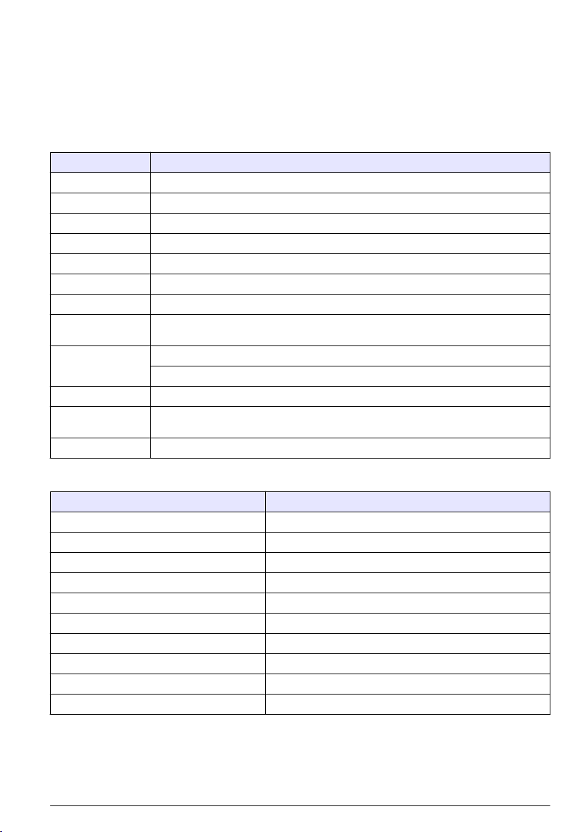
Specification Details
Dimensions 748 x 250 x 236 mm (29.4 x 9.8 x 9.3 in.)
Weight 7 kg (15.4 lb)
Sample flow rate 5—20 liters/hour
Ambient temperature 0—60 °C (32—140 °F)
Relative humidity 10—90%
Temperature sensor Pt100
Accuracy ± 1% of displayed value; temperature < ± 0.2 °C
Calculated pH
Display range
Display resolution Conductivity/resistivity: automatic point drift (minimum resolution 0.001 μS/cm) < 0.1 °C
Sample tubing
Certifications EN 61326-1: 2006; EN 61010-1: 2010
Accuracy on conductivity measurement: ± 2%; Maximum difference calculated-theoretical
value: 0.1 pH
NH3; 7 < pH < 10; 2.8 μS/cm < C1 < 28 μS/cm; C2 < 0.5 μS/cm
NaOH; 7 < pH < 10.7; 2.5 μS/cm < C1 < 125 μS/cm; C2 < 100 μS/cm
Polyethylene or PTFE or FEP; 0.2 to 6 bars (3 to 90 psi); 5 to 50 °C (40 to 120 °F); Input:
6-mm (standard) or 1/4-inch (with adapter); Output: 12-mm or 1/2-inch
Sensor
Specification Details
Sensor body material Black PSU
Conductivity electrodes, internal and external Stainless steel 316L
Cell constant K 0.01 (cm-1)
Conductivity range 0.01—200 μS.cm-1; Resistivity range: 5k Ω.cm—100 MΩ.cm
Maximum pressure 10 bar
Maximum temperature 125 °C (257 °F)
Accuracy < 2%
Temperature response < 30 seconds
Insulator PSU
Connector Glass polyester (IP65)
English 3
Page 6
Controller
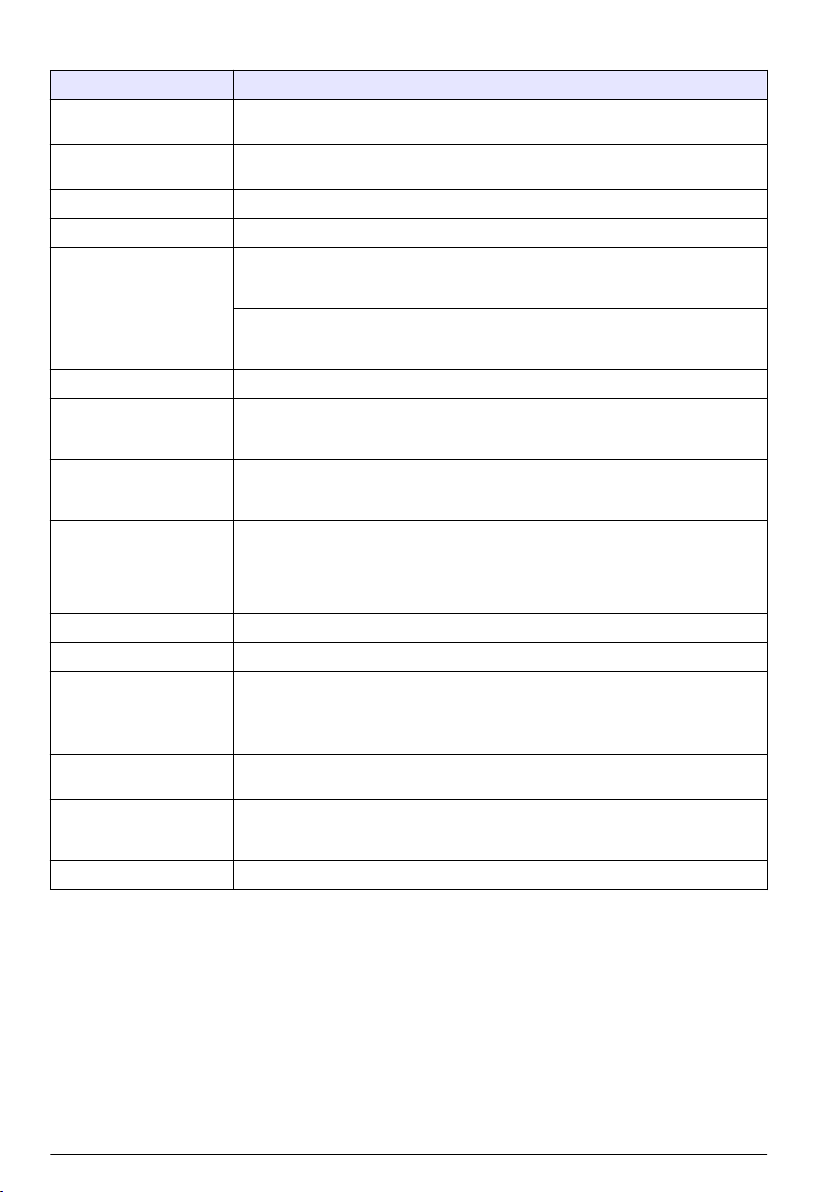
Specification Details
Component description Microprocessor-controlled and menu-driven controller that operates the sensor and
Operating temperature -20 to 60 ºC (-4 to 140 ºF); 95% relative humidity, non-condensing with sensor load
Storage temperature -20 to 70 ºC (-4 to 158 ºF); 95% relative humidity, non-condensing
Enclosure
Power requirements AC powered controller: 100-240 VAC ±10%, 50/60 Hz; Power 50 VA with 7 W
Altitude requirements Standard 2000 m (6562 ft) ASL (Above Sea Level)
Pollution
degree/Installation
category
Outputs Two analog (0-20 mA or 4-20 mA) outputs. Each analog output can be assigned to
Relays Four SPDT, user-configured contacts, rated 250 VAC, 5 Amp resistive maximum for
Dimensions ½ DIN—144 x 144 x 180.9 mm (5.7 x 5.7 x 7.12 in.)
Weight 1.7 kg (3.75 lb)
Compliance information2CE approved (with all sensor types). Listed for use in general locations to UL and
Digital communication Optional Modbus, RS232/RS485, Profibus DPV1 or HART network connection for
Data logging Secure Digital Card (32 GB maximum) or special RS232 cable connector for data
Warranty 2 years
1
1
Units that have the Underwriters Laboratories (UL) certification are intended for indoor use only and do not
have a NEMA 4X/IP66 rating.
2
DC powered units are not listed by UL.
displays measured values.
<7 W; -20 to 50 ºC (-4 to 104 ºF) with sensor load <28 W
NEMA 4X/IP66 metal enclosure with a corrosion-resistant finish
sensor/network module load, 100 VA with 28 W sensor/network module load
(optional Modbus, RS232/RS485, Profibus DPV1 or HART network connection).
24 VDC powered controller: 24 VDC—15%, + 20%; Power 15 W with 7 W
sensor/network module load, 40 W with 28 W sensor/network module load (optional
Modbus, RS232/RS485, Profibus DPV1 or HART network connection).
Polution Degree 2; Installation Category II
represent a measured parameter such as pH, temperature, flow or calculated
values. Optional module supplies three additional analog outputs (5 total).
the AC powered controller and 24 VDC, 5A resistive maximum for the DC powered
controller. Relays are designed for connection to AC Mains circuits (i.e., whenever
the controller is operated with 115 - 240 VAC power) or DC circuits (i.e., whenever
the controller is operated with 24 VDC power).
CSA safety standards by ETL (with all sensor types).
Certain AC mains powered models are listed for use in general safety locations to
UL and CSA safety standards by Underwriters Laboratories (with all sensor types).
data transmission
logging and performing software updates. The controller will keep approximately
20,000 data points per sensor.
General information
In no event will the manufacturer be liable for direct, indirect, special, incidental or consequential
damages resulting from any defect or omission in this manual. The manufacturer reserves the right to
make changes in this manual and the products it describes at any time, without notice or obligation.
Revised editions are found on the manufacturer’s website.
4
English
Page 7
Safety information
N O T I C E
The manufacturer is not responsible for any damages due to misapplication or misuse of this product including,
without limitation, direct, incidental and consequential damages, and disclaims such damages to the full extent
permitted under applicable law. The user is solely responsible to identify critical application risks and install
appropriate mechanisms to protect processes during a possible equipment malfunction.
Please read this entire manual before unpacking, setting up or operating this equipment. Pay
attention to all danger and caution statements. Failure to do so could result in serious injury to the
operator or damage to the equipment.
Make sure that the protection provided by this equipment is not impaired. Do not use or install this
equipment in any manner other than that specified in this manual.
Use of hazard information
Indicates a potentially or imminently hazardous situation which, if not avoided, will result in death or serious injury.
Indicates a potentially or imminently hazardous situation which, if not avoided, could result in death or serious
injury.
Indicates a potentially hazardous situation that may result in minor or moderate injury.
Indicates a situation which, if not avoided, may cause damage to the instrument. Information that requires special
emphasis.
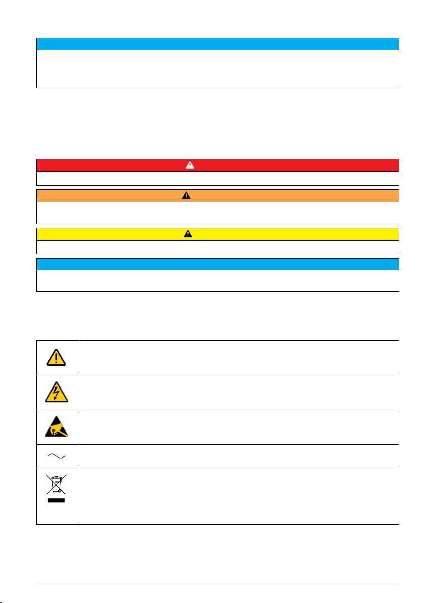
Precautionary labels
Read all labels and tags attached to the product. Personal injury or damage to the product could
occur if not observed. A symbol on the instrument is referenced in the manual with a precautionary
statement.
D A N G E R
W A R N I N G
C A U T I O N
N O T I C E
This symbol, when noted on a product, indicates a potential hazard which could cause serious
personal injury and/or death. The user should reference this instruction manual for operation and/or
safety information.
This symbol, when noted on a product enclosure or barrier, indicates that a risk of electrical shock
and/or electrocution exists and indicates that only individuals qualified to work with hazardous
voltages should open the enclosure or remove the barrier.
This symbol, when noted on the product, indicates the presence of devices sensitive to electrostatic
discharge and indicates that care must be taken to prevent damage to them.
This symbol, when noted on a product, indicates the instrument is connected to alternate current.
Electrical equipment marked with this symbol may not be disposed of in European public disposal
systems. In conformity with European local and national regulations, European electrical equipment
users must now return old or end-of-life equipment to the manufacturer for disposal at no charge to
the user.
Note: For return for recycling, please contact the equipment producer or supplier for instructions on how to return
end-of-life equipment, producer-supplied electrical accessories, and all auxiliary items for proper disposal.
English 5
Page 8
Products marked with this symbol indicates that the product contains toxic or hazardous substances
or elements. The number inside the symbol indicates the environmental protection use period in
years.
Products marked with this symbol indicates that the product conforms to relevant South Korean
EMC standards.
EMC compliance statement (Korea)
Type of equipment Additional information
A 급 기기
( 업무용 방송통신기자재 )
Class A equipment
(Industrial Broadcasting and Communication
Equipment)
이 기기는 업무용 (A 급 ) 전자파적합기기로서 판매자 또
는 사용자는 이 점을 주의하시기 바라며, 가정외의 지역
에서 사용하는 것을 목적으로 합니다.
This equipment meets Industrial (Class A) EMC
requirements. This equipment is for use in industrial
environments only.
Certification
Canadian Radio Interference-Causing Equipment Regulation, IECS-003, Class A:
Supporting test records reside with the manufacturer.
This Class A digital apparatus meets all requirements of the Canadian Interference-Causing
Equipment Regulations.
FCC Part 15, Class "A" Limits
Supporting test records reside with the manufacturer. The device complies with Part 15 of the FCC
Rules. Operation is subject to the following conditions:
1. The equipment may not cause harmful interference.
2. The equipment must accept any interference received, including interference that may cause
undesired operation.
Changes or modifications to this equipment not expressly approved by the party responsible for
compliance could void the user's authority to operate the equipment. This equipment has been tested
and found to comply with the limits for a Class A digital device, pursuant to Part 15 of the FCC rules.
These limits are designed to provide reasonable protection against harmful interference when the
equipment is operated in a commercial environment. This equipment generates, uses and can
radiate radio frequency energy and, if not installed and used in accordance with the instruction
manual, may cause harmful interference to radio communications. Operation of this equipment in a
residential area is likely to cause harmful interference, in which case the user will be required to
correct the interference at their expense. The following techniques can be used to reduce
interference problems:
1. Disconnect the equipment from its power source to verify that it is or is not the source of the
interference.
2. If the equipment is connected to the same outlet as the device experiencing interference, connect
the equipment to a different outlet.
3. Move the equipment away from the device receiving the interference.
4. Reposition the receiving antenna for the device receiving the interference.
5. Try combinations of the above.
Product components
Make sure that all components have been received. If any items are missing or damaged, contact the
manufacturer or a sales representative immediately.
6
English
Page 9
Product overview
The analyzer measures conductivity and calculates the pH in low-conductivity applications. The
system can include the controller as shown in Figure 1 or the controller can be installed as an
external component.
The system can be configured to function in numerous applications in the following industry sectors:
• Measurement in pure and ultrapure water, power plants, semiconductor industry, pharmaceutical
• Drinking water
• Industrial processes (chemistry, paper mills, sugar refineries, etc.)
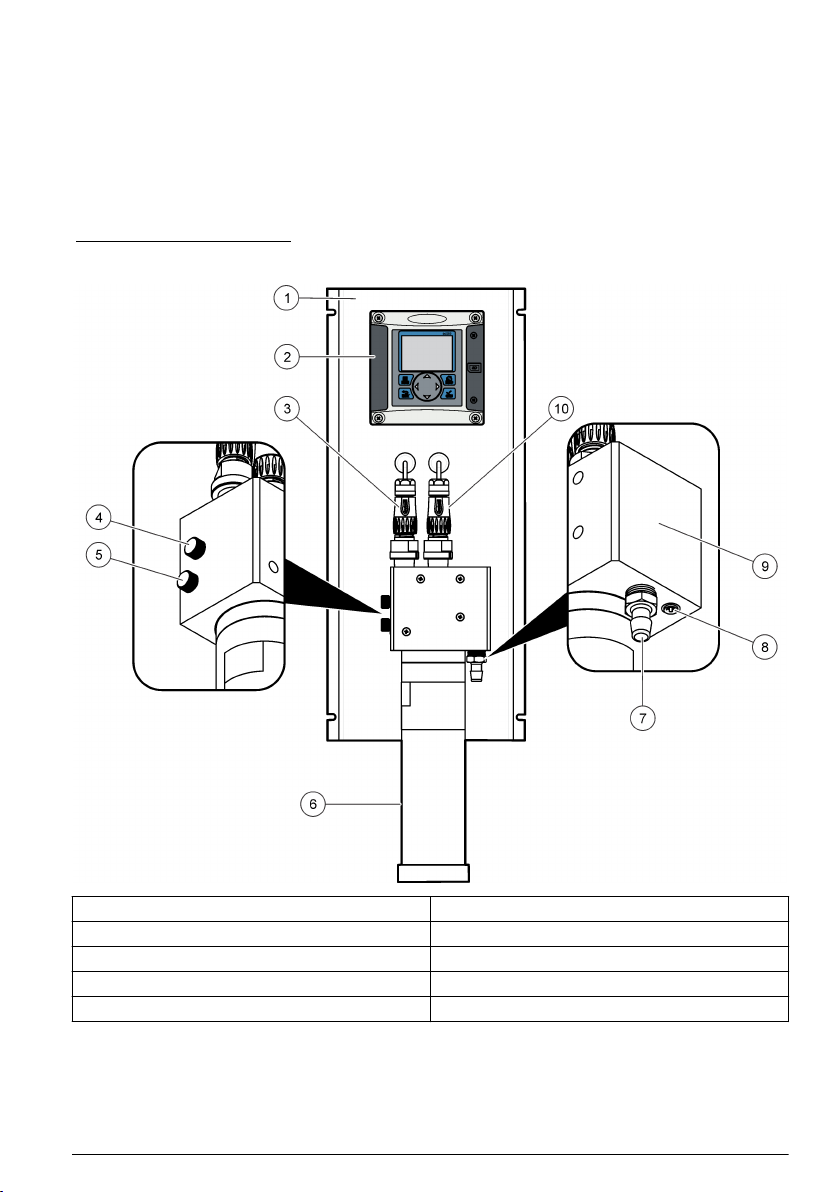
Figure 1 Analyzer overview
1 Mounting panel 6 Cationic resin cartridge
2 Controller 7 Sample output
3 Channel 1 conductivity probe 8 Sample input
4 Degassing valve 9 Measurement cell
5 Sample flow adjustment valve 10 Channel 2 conductivity probe
Principle of operation (pH calculation)
The Polymetron 9523 analyzer adheres to the recommendations contained in the guidelines for
feedwaters, boiler water and steam quality for power and industrial plants.
The pH calculations can only be applied under the following strict chemical conditions:
English
7
Page 10
• The sample must only contain an alkaline agent (ammonia, sodium hydroxide or ethanolamine)
• Any impurity is principally NaCl (sodium chloride)
• The concentration of impurity must be negligible in comparison to the alkaline agent
Control of conductivity values
Control of the minimum and maximum conductivity values depends upon the volatile conditioner.
These values are illustrated in the following two tables.
Note: AVT (All Volatile Treatment) - Conditioning concept where only volatile alkalizing agents are used; mainly
ammonia.
NH3 Conditioner:
AVT
pH 7 - 10.0
Conductivity C1 (μS/cm) 2.8 - 28
Acid conductivity C2 (μS/cm) < 0.5
NaOH Conditioner:
AVT
pH 7 - 10.7
Conductivity C1 (μS/cm) 2.5 - 125
Acid conductivity C2 (μS/cm) < 100
Installation
C A U T I O N
Multiple hazards. Only qualified personnel must conduct the tasks described in this section of the
document.
Analyzer mounting
Attach the analyzer to a stable, vertical surface. Refer to the guidelines that follow and Figure 2.
Note: If an external controller is used, refer to the controller documentation for mounting instructions.
• Put the instrument in a location that has access for operation, service and calibration.
• Make sure that there is good view of the display and controls.
• Keep the instrument away from a heat source.
• Keep the instrument away from vibrations.
• Keep the sample tubing as short as possible to minimize the response time.
• Make sure that there is no air in the sample supply line.
8
English
Page 11
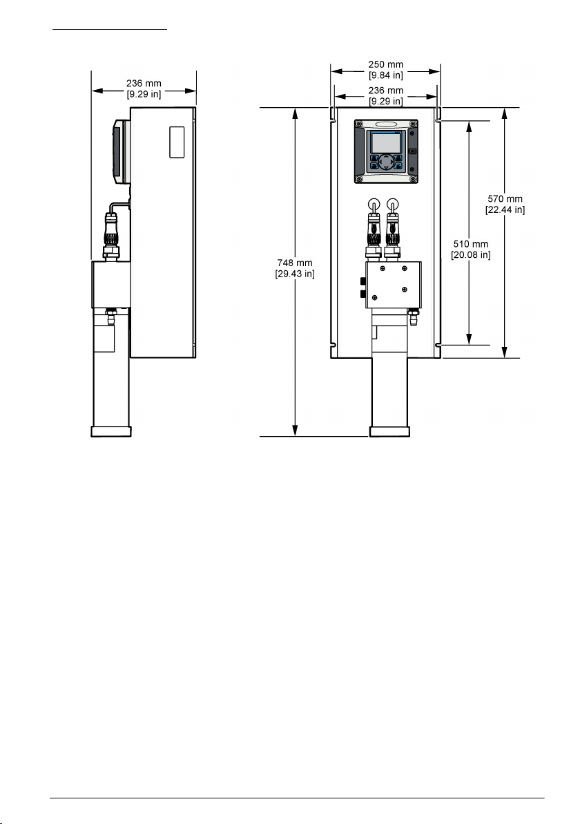
Figure 2 Dimensions
Resin cartridge installation
Refer to the steps that follow and Figure 3 to install the resin cartridge.
1. Insert the steel tube into the quick lock connector.
2. Push the steel tube as far as possible into the measuring cell.
3. Take the resin cartridge and turn it upside down 2 or 3 times until the resin comes away from the
sides of the cartridge and settles at the bottom, at the opposite end to the marker line.
4. Unscrew the cap off the top of the cartridge, by the marker line. Discard this cap and the flat black
sealing cap following the safety and disposal information for used cartridges.
5. Place the end of the steel tube into the center of the cartridge.
6. Slowly raise the cartridge to the measuring cell and screw into place to obtain an airtight and
watertight fitting.
English
9
Page 12
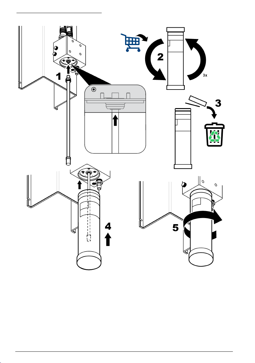
Figure 3 Resin cartridge installation
Wiring overview
Figure 4 shows an overview of the wiring connections inside the controller with the high voltage
barrier removed. The left side of the figure shows the back side of the controller cover.
Note: Remove connector caps from the connectors before module installation.
10
English
Page 13
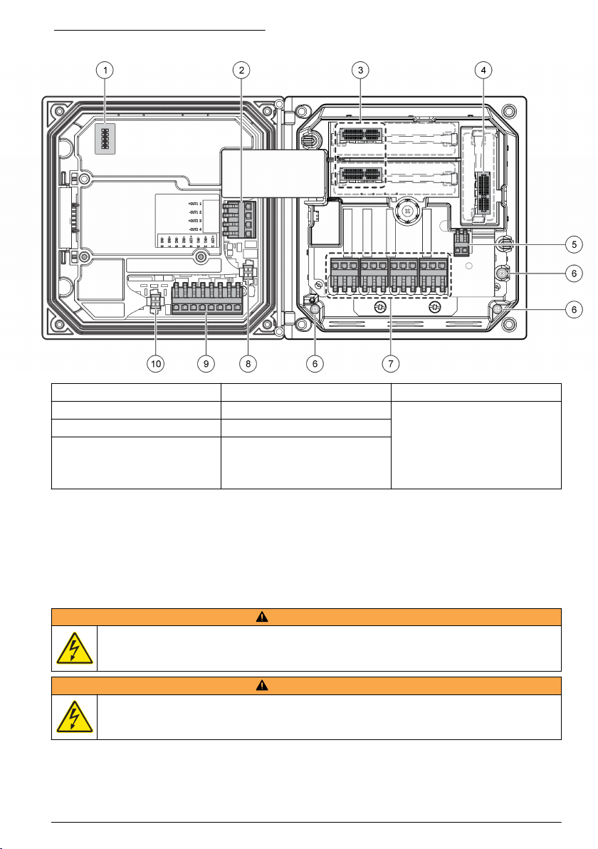
Figure 4 Wiring connections overview
1 Service cable connection 5 AC and DC power connector
2 4-20 mA output
3 Sensor module connector 7 Relay connections
4 Communication module
connector (e.g., Modbus,
Profibus, HART, optional
4-20 mA module, etc.)
1
Terminals can be removed for improved access.
1
6 Ground terminals 10 Digital sensor connector
1
8 Digital sensor connector
1
9 Discrete input wiring connector
1
1
High-voltage barrier
High-voltage wiring for the controller is located behind the high-voltage barrier in the controller
enclosure. The barrier must remain in place except when installing modules or when a qualified
installation technician is wiring for power, alarms, outputs or relays. Do not remove the barrier while
power is applied to the controller.
Wiring for power
W A R N I N G
Potential Electrocution Hazard. Always disconnect power to the instrument when making electrical
connections.
W A R N I N G
Potential Electrocution Hazard. If this equipment is used outdoors or in potentially wet locations, a
Ground Fault Interrupt device must be used for connecting the equipment to its mains power source.
1
English 11
Page 14
D A N G E R
Electrocution Hazard. Do not connect AC power to a 24 VDC powered model.
W A R N I N G
Potential Electrocution Hazard. A protective earth (PE) ground connection is required for both
100-240 VAC and 24 VDC wiring applications. Failure to connect a good PE ground connection can
result in shock hazards and poor performance due to electromagnetic interferences. ALWAYS connect
a good PE ground to the controller terminal.
Install the device in a location and position that gives easy access to the disconnect device and its operation.
N O T I C E
The controller can be purchased as either a 100-240 VAC powered model or a 24 VDC powered
model. Follow the appropriate wiring instructions for the purchased model.
The controller can be wired for line power by hard-wiring in conduit or wiring to a power cord.
Regardless of the wire used, the connections are made at the same terminals. A local disconnect
designed to meet local electrical code is required and must be identified for all types of installation. In
hard-wired applications, the power and safety ground service drops for the instrument must be 18 to
12 AWG.
Notes:
• The voltage barrier must be removed before making any electrical connections. After making all
connections, replace the voltage barrier before closing the controller cover.
• A sealing type strain relief and a power cord less than 3 meters (10 feet) in length with three 18gauge conductors (including a safety ground wire) can be used to maintain the NEMA
4X/IP66 environmental rating.
• Controllers can be ordered with AC power cords pre-installed. Additional power cords may also be
ordered.
• The DC power source that supplies power to the 24 VDC powered controller must maintain
voltage regulation within the specified 24 VDC-15% +20% voltage limits. The DC power source
must also provide adequate protection against surges and line transients.
Wiring procedure
Refer to the illustrated steps that follow and Table 1 or Table 2 to wire the controller for power. Insert
each wire into the appropriate terminal until the insulation is seated against the connector with no
bare wire exposed. Tug gently after insertion to make sure that there is a secure connection. Seal
any unused openings in the controller box with conduit opening sealing plugs.
Table 1 AC power wiring information (AC powered models only)
Terminal Description Color—North America Color—EU
1 Hot (L1) Black Brown
2 Neutral (N) White Blue
— Protective Earth (PE) Ground lug Green Green with yellow stripe
Table 2 DC power wiring information (DC powered models only)
Terminal Description Color—North America Color—EU
1 +24 VDC Red Red
2 24 VDC return Black Black
— Protective Earth (PE) Ground lug Green Green with yellow stripe
12 English
Page 15

Alarms and relays
The controller is equipped with four unpowered, single pole relays rated 100-250 VAC, 50/60 Hz,
5 amp resistive maximum. Contacts are rated 250 VAC, 5 amp resistive maximum for the AC
English
13
Page 16

powered controller and 24 VDC, 5A resistive maximum for the DC powered controller. The relays are
not rated for inductive loads.
Wiring relays
W A R N I N G
Potential Electrocution Hazard. Always disconnect power to the instrument when making electrical
connections.
W A R N I N G
Potential fire hazard. The relay contacts are rated 5A and are not fused. External loads connected to
the relays must have current limiting devices provided to limit current to < 5 A.
W A R N I N G
Potential fire hazard. Do not daisy-chain the common relay connections or jumper wire from the mains
power connection inside the instrument.
W A R N I N G
Potential electrocution hazard. In order to maintain the NEMA/IP environmental ratings of the
enclosure, use only conduit fittings and cable glands rated for at least NEMA 4X/IP66 to route cables in
to the instrument.
AC line (100—250 V) powered controllers
Potential electrocution hazard. AC mains powered controllers (115 V–230 V) are designed for relay
connections to AC mains circuits (i.e., voltages greater than 16 V-RMS, 22.6 V-PEAK or 35 VDC).
The wiring compartment is not designed for voltage connections in excess of 250 VAC.
24 VDC powered controllers
Potential electrocution hazard. 24 V powered controllers are designed for relay connections to low
voltage circuits (i.e., voltages less than 16 V-RMS, 22.6 V-PEAK or 35 VDC).
W A R N I N G
W A R N I N G
The 24 VDC controller relays are designed for the connection to low voltage circuits (i.e., voltages
less than 30 V-RMS, 42.2 V-PEAK or 60 VDC). The wiring compartment is not designed for voltage
connections above these levels.
The relay connector accepts 18–12 AWG wire (as determined by load application). Wire gauge less
than 18 AWG is not recommended.
The Normally Open (NO) and Common (COM) relay contacts will be connected when an alarm or
other condition is active. The Normally Closed (NC) and Common relay contacts will be connected
when an alarm or other condition is inactive (unless the Fail Safe is set to Yes) or when power is
removed from the controller.
Most relay connections use either the NO and COM terminals or the NC and COM terminals. The
numbered installation steps show connection to the NO and COM terminals.
14
English
Page 17

English 15
Page 18

Analog output connections
W A R N I N G
Potential Electrocution Hazard. Always disconnect power to the instrument when making electrical
connections.
W A R N I N G
Potential electrocution hazard. In order to maintain the NEMA/IP environmental ratings of the
enclosure, use only conduit fittings and cable glands rated for at least NEMA 4X/IP66 to route cables in
to the instrument.
Two isolated analog outputs (1 and 2) are provided (Figure 5). Such outputs are commonly used for
analog signaling or to control other external devices.
Make wiring connections to the controller as shown in Figure 5 and Table 3.
Note: Figure 5 shows the back of the controller cover and not the inside of the main controller compartment.
Table 3 Output connections
Recorder wires Circuit board position
Output 2– 4
Output 2+ 3
Output 1– 2
Output 1+ 1
1. Open the controller cover.
2. Feed the wires through the strain relief.
3. Adjust the wire as necessary and tighten the strain relief.
4. Make connections with twisted-pair shielded wire and connect the shield at the controlled
component end or at the control loop end.
• Do not connect the shield at both ends of the cable.
• Use of non-shielded cable may result in radio frequency emission or susceptibility levels higher
than allowed.
• Maximum loop resistance is 500 ohm.
5. Close the controller cover and tighten the cover screws.
6. Configure outputs in the controller.
16
English
Page 19

Figure 5 Analog output connections
Discrete input wiring connections
W A R N I N G
Potential Electrocution Hazard. Always disconnect power to the instrument when making electrical connections.
Potential electrocution hazard. In order to maintain the NEMA/IP environmental ratings of the enclosure, use only
conduit fittings and cable glands rated for at least NEMA 4X/IP66 to route cables in to the instrument.
Three discrete inputs are provided for switch closure inputs or logic level voltage inputs. Make wiring
connections and configure jumper settings to the controller as shown in Figure 6, Table 4 and
Figure 7.
Note: Figure 6 shows the back of the controller cover and not the inside of the main controller compartment.
Figure 6 Discrete input wiring connections
W A R N I N G
English 17
Page 20

Table 4 Input connections
Discrete inputs Connector position - Switch input Connector position - Voltage
Input 1+ 3 2
Input 1- 2 3
Input 2+ 6 5
Input 2- 5 6
Input 3+ 8 7
Input 3- 7 8
Figure 7 Jumper settings
input
1 Input 1 configuration jumpers 3 Input 3 configuration jumpers 5 Jumpers positioned to the right
2 Input 2 configuration jumpers 4 Jumpers positioned to the left for
switch inputs
for voltage inputs
1. Open the controller cover.
2. Feed the wires through the cable gland.
3. Adjust the wire as necessary and tighten the cable gland.
4. The jumpers are positioned immediately behind the connector. Remove the connector for
improved access to the jumpers and configure the jumper settings according to the type of input
as shown in Figure 7.
5. Close the controller cover and tighten the cover screws.
6. Configure inputs in the controller.
Note: In switch input mode the controller supplies 12 volts to the switch and is not isolated from the controller. In
voltage input mode the inputs are isolated from the controller (user input voltage from 0 to 30 volts).
Connect the optional digital communication output
The manufacturer supports Modbus RS485, Modbus RS232, Profibus DPV1 and HART
communication protocols. The optional digital output module is installed in the location indicated by
item 4 in Figure 4 on page 11. Refer to the instructions supplied with the network module for more
details.
For information about Modbus registers, go to http://www.hach-lange.com or http://www.hach.com
and search Modbus registers or go to any sc200 product page.
Install a Secure Digital (SD) memory card
For instructions on how to install an SD card in the controller, refer to Figure 8. Information on how to
use the SD memory card can be found in Using the secure digital memory (SD) card on page 24.
To remove an SD card, push down on the edge of the card and release, then pull the card up and out
of the slot. After the card is removed, close the slot cover and tighten the cover screws.
18
English
Page 21

Figure 8 SD card installation
Plumb the sample and drain lines
After the panel is attached to a wall, connect the sample and drain lines to the fittings on the panel.
Make sure that the tubing meets the Specifications on page 3. Refer to the steps that follow and
Figure 1 on page 7.
1. Insert the sample tubing into the input quick-connect fitting under the flow chamber (Figure 1
on page 7).
2. Connect a drain line to sample output fitting. Keep the drain line as short as possible to prevent
back-pressure.
Analyzer startup
1. Open the degassing valve.
2. Open the sample flow adjustment valve and ensure everything is watertight and there are no
leaks.
3. Close the degassing valve when the measuring cell is free of air.
4. Set the sample flow to the required rate (between 5 and 20 L/h).
5. Pass about 10 liters of sample through the resin to thoroughly rinse it and prepare the analyzer
for measurements.
User interface and navigation
User interface
The keypad has four menu keys and four directional keys as shown in Figure 9.
English
19
Page 22

Figure 9 Keypad and front panel overview
1 Instrument display 5 BACK key. Moves back one level in the menu
2 Cover for secure digital memory card slot 6 MENU key. Moves to the Settings Menu from other
3 HOME key. Moves to the Main Measurement
screen from other screens and submenus.
4 ENTER key. Accepts input values, updates, or
displayed menu options.
structure.
screens and submenus.
7 Directional keys. Used to navigate through the
menus, change settings, and increment or
decrement digits.
Inputs and outputs are set up and configured through the front panel using the keypad and display
screen. This user interface is used to set up and configure inputs and outputs, create log information
and calculated values, and calibrate sensors. The SD interface can be used to save logs and update
software.
Display
Figure 10 shows an example of the main measurement screen with the sensor connected to the
controller.
The front panel display screen shows sensor measurement data, calibration and configuration
settings, errors, warnings and other information.
20
English
Page 23

Figure 10 Example of Main Measurement screen
1 Home screen icon 7 Warning status bar
2 Sensor name 8 Date
3 SD Memory card icon 9 Analog output values
4 Relay status indicator 10 Time
5 Measurement value 11 Progress bar
6 Measurement unit 12 Measurement parameter
Table 5 Icon descriptions
Icon Description
Home screen The icon may vary depending on the screen or menu being displayed. For example, if an SD
SD memory
card
Warning A warning icon consists of an exclamation point within a triangle. Warning icons appear on the
Error An error icon consists of an exclamation point within a circle. When an error occurs, the error
card is installed, an SD card icon appears here when the user is in the SD Card Setup menu.
This icon appears only if an SD card is in the reader slot. When a user is in the SD Card Setup
menu, this icon appears in the upper left corner.
right of the main display below the measurement value. Push the ENTER key then select the
device to view any problems associated with that device. The warning icon will no longer be
displayed once all problems have been corrected or acknowledged.
icon and the measurement screen flash alternately in the main display. To view errors, push the
MENU key and select Diagnostics. Then select the device to view any problems associated
with that device.
Additional display formats
• From the Main Measurement screen push the UP and DOWN arrow keys to switch between
measurement parameters
• From the Main Measurement screen push the RIGHT arrow key to switch to a split display of up to
4 measurement parameters. Push the RIGHT arrow key to include additional measurements. Push
the LEFT arrow key as needed to return to the Main Measurement screen
• From the Main Measurement screen push the LEFT arrow key to switch to the graphical display
(see Graphical display on page 21 to define the parameters). Push the UP and DOWN arrow
keys to switch measurement graphs
Graphical display
The graph shows concentration and temperature measurements for each channel in use. The graph
supplies easy monitoring of trends and shows changes in the process.
English
21
Page 24

1. From the graphical display screen use the up and down arrow keys to select a graph and push
the HOME key.
2. Select an option:
Option Description
MEASUREMENT VALUE Set the measurement value for the selected channel. Select between Auto Scale
DATE & TIME RANGE Select the date and time range from the available options
and Manually Scale. For manual scaling enter the minimum and maximum
measurement values
System startup
When initially powered up, the LANGUAGE, DATE FORMAT and DATE/TIME screens appear in
order. After these options are set, the controller performs a device scan and displays the message
SCANNING FOR DEVICES. PLEASE WAIT... If a new device is found, the controller performs an
installation process before displaying a main measurement screen.
If the scan finds previously installed devices without configuration changes, the main measurement
screen of the device in the number one position appears immediately after the scan is complete.
If a device has been removed from the controller or is not found during the next power-cycled or
menu-driven scan, the controller displays a DEVICE MISSING message and prompts to delete the
missing device.
If no sensor is connected to an installed analog module, the controller will indicate an error. If devices
are connected but not found by the controller, refer to the Troubleshooting section of this manual.
Set the language, date and time for the first time
The controller displays the language, date and time edit screens when the controller is powered on
for the first time, and when it is powered on after the configuration settings have been set to their
default values.
After the language, date and time options are set for the first time, update the options as necessary
through the setup menu.
1. In the LANGUAGE screen, highlight a language in the options list and push the enter key.
English is the default language for the controller.
2. In the DATE FORMAT screen, highlight a format and push the enter key.
3. In the DATE/TIME screen, push the right or left arrow keys to highlight a field, then push the up
and down arrow keys to update the value in the field. Update the other fields as necessary.
4. Push the enter key. The changes are saved and the controller performs a start-up scan for
devices. If connected devices are found, the controller displays the main measurement screen for
the device in the number one position. If the controller fails to find connected devices, refer to the
Troubleshooting section of this manual.
Controller configuration information
General information about configuration options is listed in the table.
1. Push the menu key and select Polymetron 9500 SETUP.
Option Description
SECURITY SETUP Sets the passcode preferences.
OUTPUT SETUP Configures the controller analog outputs.
RELAY SETUP Configures the controller relays.
22 English
Page 25

Option Description
DISPLAY SETUP Configures the controller display.
ADJUST ORDER—View and modify the measurement display order.
• SEE CURRENT ORDER—View the current display order
• ADD MEASUREMENTS—Add selected measurements to the display
• REMOVE MEASUREMENTS—Remove selected measurements from the
display
• REORDER LIST—Select one or more measurements and change their order
in the display
• SEE DEFAULT ORDER—View the default display order
• SET TO DEFAULT—Set the display order to the default configuration
Note: Some of the above will not be available if no adjustment is possible for that
option (e.g. REORDER LIST and REMOVE MEASUREMENTS will not be
available if only one measurement is selected for display).
DISPLAY CONTRAST—Adjusts the contrast of the controller display.
EDIT NAME—Assigns a name to the controller.
SET DATE/TIME Sets the controller time and date.
DATALOG SETUP Configures data logging options. Available only if CALCULATION has been
MANAGE DATA Select the device from the list of installed components and then select VIEW
ERROR HOLD MODE HOLD OUTPUTS—Holds outputs at last known value when controller loses
CALCULATION Configures the controller math function.
Poly
9500 INFORMATION
DISCRETE INPUT
SETUP
LANGUAGE Assigns the language used in the controller.
setup.
DATA LOG or VIEW EVENT LOG depending on the type of log entry to view.
Specify the selection period to list all log entries matching the selection criteria.
Push the up and down arrows to select an entry and then push enter to view
more details.
communication with the sensor.
TRANSFER OUTPUTS—Switches to transfer mode when controller loses
communication with the sensor. Outputs transfer to a pre-defined value.
SET VARIABLE X—Selects the sensor for the x variable.
SET PARAMETER X—Selects the sensor measurement for the x variable.
SET VARIABLE Y—Selects the sensor for the y variable.
SET PARAMETER Y—Selects the sensor measurement for the y variable.
SET FORMULA—Select the math function to implement:
• None—Disables the math function
• X-Y—Subtraction function
• X+Y—Addition function
• X/Y—Division function
• [X/Y]%—Percentage function
• [X+Y]/2—Average function
• [X*Y]—Multiplication function
• [X-Y]%/X—Difference function
DISPLAY FORMAT—Selects the number of digits and decimal points.
SET UNITS—Selects the units for the calculated reading.
SET PARAMETER—Selects the parameter for the calculated reading.
Displays information about the controller including serial number and software
versions.
Configures three discrete input channels.
English 23
Page 26

2. Select an option and push enter to activate the menu item.
Using the secure digital memory (SD) card
An SD card must be installed in the controller.
• The SD card can be used to update software and firmware and to download event and data logs. If
the SD card is installed while the controller is in the main menu, push the home key and then the
menu key to verify the option is visible. The SD icon will also be visible in the upper status bar of
the main measurement screen when a card is installed.
• Data log files on the SD card are available in XML and binary formats.
• DataCom is used to convert files from binary to CSV format. Refer to the DataCom manual for
more information on how to use the application. For a copy of the DataCom manual, software
updates or other downloadable resources, go to http://www.hach-lange.com or
http://www.hach.com and search DataCom.
Updating software
Notes:
• The controller does not automatically transfer information to or from an SD card.
• When the SD card is put in multiple controllers, each controller has a separate set of folders in the
SD card memory. To make sure software updates are in the correct folder for the controller in use,
it is best to use a separate dedicated SD card for each controller.
1. Push the menu key and select SD CARD SETUP.
2. Select UPGRADE SOFTWARE and push the enter key.
Note: If the UPGRADE SOFTWARE option does not appear, perform the steps in Firmware updates with SD
cards on page 26.
3. Select a device from the list and push the enter key. The list of options includes the controller and
all connected devices that have software placed in the appropriate folder on the SD card.
4. If more than one version of the upgrade software is available, select the version with the highest
number and push the enter key.
5. Push the enter key to begin the software transfer. The display will show "TRANSFERRING
FILES. PLEASE WAIT..." The percentage of completion appears in the bottom left corner of the
display. The upgrade cannot be halted once it has begun.
• When the transfer is successful, the display will show "TRANSFER COMPLETE" along with a
prompt to push enter to restart the controller or to push the back key and exit to the SD CARD
SETUP menu. Controller updates take effect when the controller is restarted. A restart is not
necessary for sensor updates.
• If the transfer is unsuccessful, the display will show "TRANSFER FAILED" and an error
message. Push the enter key to acknowledge the warning and exit out of the menu. Error
messages are different for each sensor. Refer to the applicable sensor manual.
Save data and event logs with SD cards
Notes:
• Data and event logs can be downloaded to an SD card and viewed with any device capable of
reading an SD card.
• Data logs store the measurement data at selected intervals in a packed binary format (.flg file).
• Event logs store a variety of events that occur on the devices such as configuration changes,
alarms, and warning conditions. Event logs are set up during the sensor or module configuration
process. Event logs are stored in a CSV format.
1. Push the menu key and select SD CARD SETUP>SAVE LOGS.
2. If more than one device appears on the screen, all devices are selected by default. To deselect
an item, highlight the selection and push the left arrow key. Select the devices from which logs
will be saved and push the enter key.
24
English
Page 27

3. Select the time period from which logs are to be saved.
Option Description
LAST DAY All logs from the last full 24 hours, starting from 12:00 a.m., and any additional time
LAST WEEK All logs from the last full week (7 days) starting from 12:00 a.m., and any additional time
LAST MONTH All logs from the last full month (30 days) starting from 12:00 a.m., and any additional time
ALL Save all logs in memory.
NEW All logs that are new since the last time logs were saved to the SD card.
remaining on the current day.
remaining on the current day.
remaining on the current day.
4. Push the enter key to confirm the choice, and push the enter key again to begin the file transfers.
5. Allow time for the files to transfer. The display will show TRANSFERRING FILES. PLEASE
WAIT... and the percentage of files transferred. If the transfer is successful, the display will show
"TRANSFER COMPLETE". If the transfer is not successful, the display will show "TRANSFER
FAILED".
6. Push the enter key to return to the SD CARD SETUP menu.
Access data and event log files on the SD card
A PC, a USB or other SD card reader device, Excel 2003 or higher (for XML files) or the DataCom
application (for binary flg files) are necessary to view the event and data logs stored on an SD card.
Data logs have the following structure: Device Name, Device Serial Number, Device Identification,
Data Log, Time Stamp.
Event logs have the following structure: Device Name, Device Serial Number, Device Identification,
Event Log, Time Stamp.
To view data or event log files stored on the SD card:
1. Attach the card reader device to the PC (if necessary) and install the SD card that contains the
files in the reader device.
2. In the SD card directory, open the HACH folder.
3. Select the Logs folder.
4. Select a device folder.
The event and data log files in the folder are shown.
5. To view XML data log files:
a. Make sure the HachDatalog.xsl style sheet exists in the device folder.
b. Open the Excel application.
c. Go to File, Open.
d. Select the data log file.
e. In the Import XML dialog box, select Open the file with the following style sheet applied
and select HachDatalog.xml.
f. Click OK to view the data.
6. To view binary data log (.flg) files:
a. Make sure the device driver (.flg.drv) file exists in the device folder.
b. Open DataCom.
c. In the File Viewer section, click Open.
d. Select the data log file.
The data log file is shown in the box and a comma separated values (csv) file with the same
file name is created. This csv file can be opened in Excel.
English
25
Page 28

Firmware updates with SD cards
The latest firmware updates can be placed on an SD card. The SD card can then be used to update
the controller or device firmware.
A PC and a USB card reader or other device capable of reading an SD card are necessary.
1. Find the zip file at http://www.hach-lange.com or http://www.hach.comand copy it to the PC.
2. Extract file(s) from the zip folder and save them to the SD card.
3. Remove the SD card and update the controller and device firmware. Refer to Updating software
on page 24.
Backup settings to an SD card
Saves the configuration of a device to the SD card.
1. Push the menu key and select SD CARD SETUP>MANAGE CONFIGURATION>BACKUP
SETTINGS.
2. Select the devices to be backed up. All devices are selected by default. To deselect an item,
highlight the selection and push the left arrow key. Push enter to begin the file transfers. If
backup files already exist on the SD card, a confirmation window appears. Select the devices
again and push enter. Wait for the "TRANSFER COMPLETE" message.
3. Push enter again to return to the MANAGE CONFIGURATION menu.
Restore settings to the controller
This menu selection only appears if a (serial number-specific) backup file for the controller or one of
the sensors connected to it exists on the SD Card. This menu selection loads the configuration of a
specific device from the SD card to the same device (serial number-controlled function).
1. Push the menu key and select SD CARD SETUP>MANAGE CONFIGURATION>RESTORE
SETTINGS.
2. Select the device that will be restored. All devices are selected by default. To deselect an item,
highlight the selection and push the left arrow key. Push enter to begin the file transfers.
3. To have the settings take effect immediately, push enter to restart the controller or push the back
key to return to the MANAGE CONFIGURATION menu.
Transfer settings to another device
Allows the configuration settings for a device to be transferred to an SD card and then to another
device of the same type.
1. Push the menu key and select SD CARD SETUP>MANAGE CONFIGURATION>TRANSFER
SETTINGS.
2. Two options appear:
• RETRIEVE SETTINGS
• COPY SETTINGS
3. To retrieve settings from the controller (or a device connected to it) and put the settings on the SD
card:
a. Select RETRIEVE SETTINGS and push enter.
b. Select the devices that contain the information to be transferred. All devices are selected by
default. To deselect an item, highlight the selection and push the left arrow key. Push enter to
begin the file transfers. Wait for the "TRANSFER COMPLETE" message.
c. If files already exist on the SD card, a confirmation window appears. Select the devices again
and push enter. Wait for the "TRANSFER COMPLETE" message.
26
English
Page 29

d. Push enter to return to the MANAGE CONFIGURATION menu.
4. To copy settings from the SD card to a controller (or a device connected to it):
a. Select COPY SETTINGS and push enter.
b. Select the devices on the SD card. All devices are selected by default. To deselect an item,
highlight the selection and push the left arrow key. Push enter to begin the file transfers. Wait
for the "TRANSFER COMPLETE" message.
c. When the transfer is complete, push enter to restart the connected devices.
d. Push enter to restart the controller or push back to return to the MANAGE CONFIGURATION
menu.
Operation
Contacting conductivity sensor configuration
Use the CONFIGURE menu to enter identification information for the sensor and to change options
for data handling and storage.
1. Push the menu key and select SENSOR SETUP>[Select Sensor]>CONFIGURE.
2. Select an option and push enter. To enter numbers, characters or punctuation, push and hold the
up or down arrow keys. Push the right arrow key to advance to the next space.
Option Description
EDIT NAME Changes the name that corresponds to the sensor on the top of the measure screen.
SENSOR S/N Allows the user to enter the serial number of the sensor, limited to 16 characters in any
SELECT MEASURE Changes the measured parameter to CONDUCTIVITY (default), TDS (total dissolved
DISPLAY FORMAT Changes the number of decimal places that are shown on the measure screen. When
MEAS UNITS Changes the units for the selected measurement—select the unit from the list
TEMP UNITS Sets the temperature units to °C (default) or °F.
T-COMPENSATION Adds a temperature-dependent correction to the measured value:
The name is limited to 16 characters in any combination of letters, numbers, spaces or
punctuation. Only the first 12 characters are displayed on the controller.
combination of letters, numbers, spaces or punctuation.
solids), SALINITY or RESISTIVITY. All other configured settings are reset to the
default values.
Note: If SALINITY is selected, the measurement unit is defined as ppt (parts per
thousand) and cannot be changed.
set to auto, the number of decimal places changes automatically with changes in the
measured value.
available.
• NONE—Temperature compensation not required
• USP—Set the alarm level for the standard USP definition table
• ULTRA PURE WATER—Not available for TDS. Set the compensation type
according to the sample characteristics—Select NaCl , HCl, AMMONIA or ULTRA
PURE WATER
• USER—Select BUILT IN LINEAR, LINEAR or TEMP TABLE:
• BUILT IN LINEAR—Use the pre-defined linear table (slope defined as 2.0%/°C,
reference temperature as 25 °C)
• LINEAR—Set the slope and reference temperature parameters if different from
the built-in parameters
• TEMP TABLE—Set the temperature and multiplication factor points (refer to the
conductivity module documentation)
• NATURAL WATER—Not available for TDS
English 27
Page 30

Option Description
CONFIG TDS TDS only—changes the factor that is used to convert conductivity to TDS: NaCl
CABLE PARAM Sets the sensor cable parameters to improve measurement accuracy when the sensor
TEMP ELEMENT Sets the temperature element to PT100 or PT1000 for automatic temperature
FILTER Sets a time constant to increase signal stability. The time constant calculates the
LOG SETUP Sets the time interval for data storage in the data log—5, 30 seconds, 1, 2, 5, 10,
RESET DEFAULTS Sets the configuration menu to the default settings. All sensor information is lost.
(0.49 ppm/µS) or CUSTOM (enter factor between 0.01 and 99.99 ppm/µS).
cable is extended or shortened from the standard 5 m. Enter the cable length,
resistance and capacitance.
compensation. If no element is used, the type can be set to MANUAL and a value for
temperature compensation can be entered.
average value during a specified time—0 (no effect) to 60 seconds (average of signal
value for 60 seconds). The filter increases the time for the sensor signal to respond to
actual changes in the process.
15 (default), 30, 60 minutes.
Resin option
Use the RESIN option to view and change the parameters related to the resin cartridge. These
parameters must be defined before the analyzer is used for the first time.
1. Push the menu key and select TEST/MAINT>RESIN.
2. To monitor the status of the resin select the TRACK option and push enter.
Option Description
YES Monitor the resin status. When the life expectancy of the resin is less than 10 days a warning
message is triggered. When the life expectancy reaches 0 days a system error is triggered.
NO The resin is not monitored.
3. To view the current status of the resin select the STATUS option and push enter. The date the
resin was last changed and the current life expectancy are displayed. Push back to return to the
menu or enter to reset the parameters.
4. To reset the resin parameters select PARAMETERS and push enter. Based on the values input,
the life expectancy of the resin is recalculated.
Option Description
CAPACITY Use the arrow keys to enter the resin exchange capacity (0.5 to 5.0 mole/liter).
VOLUME Use the arrow keys to enter the volume of resin (0.5 to 20 liters).
FLOW Use the arrow keys to enter the sample flow rate through the cartridge (2 to
CONCENTRATION Use the arrow keys to enter the resin concentration (0 to 20 ppm).
20 liters/hour).
Calibration
About sensor calibration
The sensor characteristics slowly shift over time and cause the sensor to lose accuracy. The sensor
must be calibrated regularly to maintain accuracy. The calibration frequency varies with the
application and is best determined by experience.
Use air (zero calibration) and the process sample to define the calibration curve. When the process
sample is used, the reference value must be determined with a secondary verification instrument.
Cell constant
Before making a calibration make sure the sensor cell parameters are correct.
28
English
Page 31

1. Push the menu key and select SENSOR SETUP>[Select Sensor]>CALIBRATE.
2. If the pass code is enabled in the security menu for the controller, enter the pass code.
3. Select CELL CONSTANT and push enter.
4. Contacting conductivity sensors: Select the cell K range for the sensor (0.01, 0.1 or 1.0) then
enter the actual K value as printed on the label attached to the sensor.
Inductive conductivity sensors: Enter the actual K value as printed on the label attached to the
sensor.
Temperature calibration
It is recommended to calibrate the temperature sensor once a year. Calibrate the temperature sensor
before calibrating the measurement sensor.
1. Measure the temperature of the water with an accurate thermometer or independent instrument.
2. Push the menu key and select SENSOR SETUP>CALIBRATE.
3. If the pass code is enabled in the security menu for the controller, enter the pass code.
4. Select 1 PT TEMP CAL and push enter.
5. The raw temperature value is displayed. Push enter.
6. Enter the correct value if different from that displayed and push enter.
7. Push enter to confirm the calibration. The temperature offset is displayed.
Zero calibration procedure
Use the zero calibration procedure to define the unique zero point of the sensor.
1. Remove the sensor from the process. Wipe with a clean towel to make sure the sensor is dry.
2. Push the menu key and select SENSOR SETUP>[Select Sensor]>CALIBRATE.
3. If the pass code is enabled in the security menu for the controller, enter the pass code.
4. Select ZERO CAL and push enter.
5. Select the option for the output signal during calibration:
Option Description
ACTIVE The instrument sends the current measured output value during the calibration procedure.
HOLD The sensor output value is held at the current measured value during the calibration procedure.
TRANSFER A preset output value is sent during calibration. Refer to the controller user manual to change
6. Place the sensor in air, push enter.
7. Review the calibration result:
• PASS—the sensor is calibrated and ready to measure samples.
• FAIL—the calibration is outside of accepted limits. Clean the sensor and retry. Refer to
Troubleshooting on page 32 for more information.
8. If the calibration passed, push enter to continue.
9. If the option for operator ID is set to YES in the CAL OPTIONS menu, enter an operator ID. Refer
to Change calibration options on page 30.
10. On the NEW SENSOR screen, select whether the sensor is new:
Option Description
YES The sensor was not calibrated previously with this controller. The days of operation and previous
NO The sensor was calibrated previously with this controller.
the preset value.
calibration curves for the sensor are reset.
English 29
Page 32

11. Return the sensor to the process and push enter. The output signal returns to the active state
and the measured sample value is shown on the measure screen.
Note: If the output mode is set to hold or transfer, select the delay time when the outputs return to the active
state.
Calibration with the process sample
The sensor can remain in the process sample.
1. Push the menu key and select SENSOR SETUP>CALIBRATE.
2. If the pass code is enabled in the security menu for the controller, enter the pass code.
3. Select SAMPLE CAL and push enter.
4. Select the option for the output signal during calibration:
Option Description
ACTIVE The instrument sends the current measured output value during the calibration procedure.
HOLD The sensor output value is held at the current measured value during the calibration procedure.
TRANSFER A preset output value is sent during calibration. Refer to the controller user manual to change
5. With the sensor in the process sample, push enter. The measured value is shown. Wait for the
value to stabilize and push enter.
6. With a certified secondary verification instrument measure the concentration value of the sample.
To avoid impurities in the sample take the measurement before the sample enters the flow
chamber. Use the arrow keys to enter this value if different from the value displayed and push
enter.
7. Review the calibration result:
• PASS—the sensor is calibrated and the calibration factor is displayed.
• FAIL—the calibration is outside of accepted limits. Clean the sensor and retry. Refer to
Troubleshooting on page 32 for more information.
8. If the calibration passed, push enter to continue.
9. If the option for operator ID is set to YES in the CAL OPTIONS menu, enter an operator ID. Refer
to Change calibration options on page 30.
10. On the NEW SENSOR screen, select whether the sensor is new:
Option Description
YES The sensor was not calibrated previously with this controller. The days of operation and previous
NO The sensor was calibrated previously with this controller.
11. With the sensor still in the process push enter. The output signal returns to the active state and
the measured sample value is shown on the measure screen.
Note: If the output mode is set to hold or transfer, select the delay time when the outputs return to the active
state.
the preset value.
calibration curves for the sensor are reset.
Change calibration options
The user can set a calibration reminder or include an operator ID with calibration data from this
menu.
1. Push the menu key and select SENSOR SETUP>[Select Sensor]>CALIBRATE.
2. If the pass code is enabled in the security menu for the controller, enter the pass code.
30
English
Page 33

3. Select CAL OPTIONS and push enter.
4. Use the arrow keys to select an option and push enter.
Option Description
CAL REMINDER Sets a reminder for the next calibration in days, months or years—select the required
OP ID ON CAL Includes an operator ID with calibration data—YES or NO (default). The ID is entered
delay from the list.
during the calibration.
Maintenance
D A N G E R
Multiple hazards. Only qualified personnel must conduct the tasks described in this section of the document.
Service schedule
The following table shows the recommended service schedule:
Validation (check with referenced measure) X X X X
Calibration (measure) X X
Calibration (temperature) X
Cleaning and decontamination
Always remove power from the controller before performing maintenance activities.
The analyzer does not normally require any cleaning or decontamination. If needed, clean the
exterior of the instrument with a moist cloth and a mild soap solution. Never use cleaning agents
such as turpentine, acetone or similar products to clean the instrument, including the display and any
accessories.
Every 3 Months Every 6 Months Yearly As Needed
D A N G E R
Replace the resin
C A U T I O N
Chemical exposure hazard. Dispose of chemicals and wastes in accordance with local, regional and
national regulations.
The cartridge of resin can be replaced with a new cartridge, or as an alternative, keep the cartridge
and replace only the resin. In order to take advantage of the full system specifications, we
recommend the use of nuclear grade cationic resin.
1. Stop the sample flow using the sample flow adjustment valve.
2. Replace the cartridge or resin:
• Cartridge—refer to Resin cartridge installation on page 9.
• Resin—refer to Figure 11. Make sure to add deionized water at regular intervals when new
resin is added to compact the resin.
3. Open the degassing valve.
4. Open the sample flow adjustment valve and ensure everything is watertight and there are no
leaks.
5. Close the degassing valve when the measuring cell is free of air.
English
31
Page 34

6. Set the sample flow to the required rate (between 5 and 20 L/h).
7. Reset the resin options. Refer to Resin option on page 28.
Figure 11 Resin replacement
Fuse replacement
Fuses are not user-serviceable items. The need for fuse replacement in controllers indicates severe
technical failure and is therefore considered to be a service activity. If a blown fuse is suspected,
contact Technical Support.
Battery replacement
The lithium ion backup battery is not user replaceable. Contact Technical Support for replacement.
Troubleshooting
Test and maintenance menu
1. Push the menu key and select TEST/MAINT.
Option Description
SCAN DEVICES Performs a scan for active and missing devices.
OUTPUT CAL
• OUTPUT 1
• OUTPUT 2
32 English
Lets the user calibrate the 4–20 mA outputs with a 250 ohm resistor in series to
the mA output terminals. The settings for each output are adjusted until the
correct value (4 mA or 20 mA) is supplied.
CAL 4 mA output (Min: 0 Max: 25000)
CAL 20 mA output (Min: 35000 Max: 65533)
Page 35

Option Description
HOLD OUTPUTS Sets the value the controller sends to an external system for a defined period of
TEST OUTPUT
• OUTPUT 1
• OUTPUT 2
STATUS View status of all modules, sensors and relays.
TEST RELAY—A, B, C, D ENERGIZE or DE-ENERGIZE the selected relay.
OVERFEED RESET Resets the overfeed timer.
RESET DEFAULT
CONFIG
RESTART Performs a controller restart.
SIMULATION (only
displays if sensors or
modules are connected)
MODBUS STATS Displays Error and Good count stats for selected port.
time. After the time period, the instrument goes back to reporting real time
values.
ACTIVATION—LAUNCH or RELEASE
SET OUTMODE—HOLD OUTPUTS (default) or TRANSFER OUTPUTS
SET CHANNELS—ALL (default) or select from hardware list
Lets the user select a mA value that is sent by the controller for verification.
Min: 0 mA (default +04.00)
Max: 25.00 mA
Resets the controller configuration settings to the default values (language, date
and time, relay function and data output function).
After the SIM VALUE is entered, the controller outputs this value as if it was the
value sent from the sensor. The simulation stops after the user exits the screen.
SELECT SOURCE—
• <Module 1>
• <Module 2>
(footer displays current source selection)
SET PARAMETER—Source measurement type (footer displays current source
selection)
SET SIM VALUE—Use arrow keys to change value (footer displays current
source selection)
• Sensor port 1, 2, 3 or 4
• Network port
• Service port
• Clear stats
SYSTEM DATA Displays the current system current, temperature and voltage data.
Sensor diagnostic and test menu
The sensor diagnostic and test menu shows current and historical information about the instrument.
Refer to Table 6.
Table 6 Sensor DIAG/TEST menu
Option Description
MODULE INFORMATION Shows information about the sensor module.
SENSOR INFORMATION Shows the name and serial number that was entered
CAL DAYS Shows the number of days since the last calibration.
CAL HISTORY Shows a list of all calibrations by date/time stamp. Use
by the user.
the arrows keys to select a calibration and push enter
to view the details.
English 33
Page 36

Table 6 Sensor DIAG/TEST menu (continued)
Option Description
RESET CAL HISTORY Resets the calibration history for the sensor (requires
POLARIZATION Contacting conductivity sensors only. Shows
SENSOR SIGNALS Shows the current sensor signal information.
FACTORY CAL Reserved for service technicians only.
DIAG MEAS Shows diagnostic information about the current
service-level passcode). All previous calibration data is
lost.
information about the electrode polarization, the cable
capacitance and the time before the next
measurement.
measurement.
Warning and error conditions
Follow the steps below to acknowledge controller warnings.
1. Push the menu key and select DIAGNOSTICS.
2. Select the device (controller, sensor, network card) with the warning or error and push enter.
3. Select the warning, error or event list and push enter.
4. Select YES and push enter to acknowledge the warning.
Note: Errors cannot be acknowledged.
Warning list
A warning icon consists of an exclamation point within a triangle. Warning icons appear on the right
of the main display below the measurement value. A warning does not affect the operation of menus,
relays and outputs. To view warnings, push the menu key and select DIAGNOSTICS. Then select
the device to view any problems associated with that device. The warning icon will no longer be
displayed once the problem has been corrected or acknowledged.
A list of possible warnings is shown in Table 7.
Table 7 Warning list for conductivity sensors
Warning Description Resolution
MEAS TOO HIGH The measured value is > 2 S/cm,
1,000,000 ppm, 200% or 20,000 ppt
MEAS TOO LOW The measured value is < 0 μS/cm,
0 ppm, 0% or 0 ppt
ZERO TOO HIGH The zero calibration value is too
high
ZERO TOO LOW The zero calibration value is too low
TEMP TOO HIGH The measured temperature is >
200 °C
TEMP TOO LOW The measured temperature is <
-20 °C
CAL OVERDUE The Cal Reminder time has expired Calibrate the sensor.
NOT CALIBRATED The sensor has not been calibrated Calibrate the sensor.
Make sure that the display format is
set for the correct measurement
range
Make sure that the sensor is
configured for the correct cell
constant.
Make sure that the sensor is held in
air during zero calibration and is not
located near radio frequency or
electromagnetic interference. Make
sure that the cable is shielded by
metal conduit.
Make sure that the sensor is
configured for the correct
temperature element.
34 English
Page 37

Table 7 Warning list for conductivity sensors (continued)
Warning Description Resolution
REPLACE SENSOR The sensor has been in operation >
365 days
CAL IN PROGRESS A calibration was started but not
completed
OUTPUTS ON HOLD During calibration, the outputs were
set to hold for a selected time.
WRONG LINEAR TC The user-defined linear temperature
compensation is out of range
WRONG TC TABLE The user-defined temperature
compensation table is out of range
WRNG USER CONC TABLE The concentration measurement is
outside of the range of the user
table
WRNG BLT-IN TEMP TABLE The measured temperature is
outside of the range of the built-in
temperature compensation table
WRNG BLT-IN CONC TABLE The concentration measurement is
outside of the range of the built-in
concentration table
Calibrate the sensor with a
reference solution and reset the
sensor days. Refer to Sensor
diagnostic and test menu
on page 33. If the calibration fails,
call technical support.
Return to calibration.
The outputs will become active after
the selected time period.
The value must be between 0 and
4%/°C; 0 to 200 °C.
The temperature is above or below
the temperature range defined by
the table.
Make sure that the user table is set
for the correct measurement range.
Make sure that the temperature
compensation is configured
correctly.
Make sure that the concentration
measurement is configured for the
correct chemical and range.
Error list
Errors may occur for various reasons. An error icon consists of an exclamation point within a circle.
When an error occurs, the error icon and the measurement screen flash alternately in the main
display. All outputs are held when specified in the controller menu. To view errors, push the menu
key and select DIAGNOSTICS. Then select the device to view any problems associated with that
device.
A list of possible errors is shown in Table 8.
Table 8 Error list for conductivity sensors
Error Description Resolution
ADC FAILURE The analog to digital conversion
failed
SENSOR MISSING The sensor is missing or
disconnected
SENS OUT RANGE The sensor signal is outside of the
accepted limits (2 S/cm)
Make sure that the sensor module is
fully inserted into the controller
connector. Replace the sensor
module.
Examine the wiring and connections
for the sensor and for the module.
Make sure that the terminal block is
fully inserted into the module.
Make sure that the display format is
set for the correct measurement
range.
Spare parts and accessories
Note: Product and article numbers may vary for some selling regions. Contact the appropriate distributor or refer to
the company website for contact information.
English
35
Page 38

Description Item no.
Conductivity probe 08310=A=0000
Cable for 8310 probe (1 meter) 09123=A=8001
Dual measurement cell 09523=C=0100
Sample flow adjustment valve 09184=C=4010
O-Ring for flow regulation valve 429=042=019
Outlet quick connector 583=012=012
Spare resin cartridge complete with resin 09523=A=7000
Viton flat gasket 09123=C=0500
Cationic resin cartridge (empty) 09523=C=0200
Resin cartridge closure 09523=C=0300
Sample outlet tube (1 meter) 359110,52012
Cationic resin (2 liters) 09523=A=7010
Material safety data sheets (MSDS)
MSDS - Cationic resin
The information listed below corresponds to our current state of knowledge. They serve as a
description of the products in regard to necessary safety measures and do not guarantee the
described chemical properties. These indications describe the safety precautions to take against the
related product and they are not a guaranty of the described product properties.
1. IDENTIFICATION OF THE SUBSTANCE
Product name: LEWATIT S 100 G1
2. COMPOSITION / INFORMATION ON INGREDIENTS
CAS no: 69011-20-7
Styrene-divinylbenzene-copolymer with sulphonic acid groups in H-form - 45-50% (weight)
3. HAZARDS IDENTIFICATION
Risk of serious damage to eyes.
4. FIRST AID MEASURES
Inhalation: Move exposed person to fresh air. Keep person warm and at rest. If not breathing, if breathing is
irregular or if respiratory arrest occurs, provide artificial respiration or oxygen by trained personnel. It may be
dangerous to the person providing aid to give mouth-to-mouth resuscitation. Get medical attention if adverse
health effects persist or are severe. If unconscious, place in recovery position and get medical attention
immediately. Maintain an open airway. Loosen tight clothing such as a collar, tie, belt or waistband.
Ingestion: Wash out mouth with water. Move exposed person to fresh air. Keep person warm and at rest. If
material has been swallowed and the exposed person is conscious, give small quantities of water to drink. Stop if
the exposed person feels sick as vomiting may be dangerous. Do not induce vomiting unless directed to do so by
medical personnel. If vomiting occurs, the head should be kept low so that vomit does not enter the lungs. Get
medical attention if adverse health effects persist or are severe. Never give anything by mouth to an unconscious
person. If unconscious, place in recovery position and get medical attention immediately. Maintain an open
airway. Loosen tight clothing such as a collar, tie, belt or waistband.
36 English
Page 39

4. FIRST AID MEASURES
Skin contact: Flush contaminated skin with plenty of water. Remove contaminated clothing and shoes. Get
medical attention if symptoms occur. Wash clothing before reuse. Clean shoes thoroughly before reuse.
Eye contact: Get medical attention immediately. Immediately flush eyes with plenty of water, occasionally lifting
the upper and lower eyelids. Check for and remove any contact lenses. Continue to rinse for at least 10 minutes.
Chemical burns must be treated promptly by a physician.
5. FIRE FIGHTING MEASURES
Extinguishing media: In case of fire, use water spray (fog), foam, dry chemical or CO2.
Fire-fighters should wear appropriate protective equipment and self-contained breathing apparatus (SCBA) with a
full face-piece operated in positive pressure mode.
6. MEASURES IN CASE OF ACCIDENTAL SPILLAGE
No action shall be taken involving any personal risk or without suitable training. Keep unnecessary and
unprotected personnel from entering. Do not touch or walk through spilt material. Provide adequate ventilation.
Put on appropriate personal protective equipment (see Section 8).
Avoid dispersal of spilt material and runoff and contact with soil, waterways, drains and sewers. Inform the
relevant authorities if the product has caused environmental pollution (sewers, waterways, soil or air).
Move containers from spill area. Vacuum or sweep up material and place in a designated, labelled waste
container. Dispose of via a licensed waste disposal contractor.
Move containers from spill area. Prevent entry into sewers, water courses, basements or confined areas. Vacuum
or sweep up material and place in a designated, labelled waste container. Dispose of via a licensed waste
disposal contractor.
7. HANDLING AND STORAGE
Put on appropriate personal protective equipment (see Section 8). Eating, drinking and smoking should be
prohibited in areas where this material is handled, stored and processed. Workers should wash hands and face
before eating, drinking and smoking. Do not get in eyes or on skin or clothing. Do not ingest. Keep in the original
container or an approved alternative made from a compatible material, kept tightly closed when not in use. Empty
containers retain product residue and can be hazardous.
Store between the following temperatures: -20 to 40 °C (-4 to 104 °F). Store in accordance with local regulations.
Store in original container protected from direct sunlight in a dry, cool and well-ventilated area, away from
incompatible materials (see section 10) and food and drink. Keep container tightly closed and sealed until ready
for use. Containers that have been opened must be carefully resealed and kept upright to prevent leakage. Do
not store in unlabelled containers. Use appropriate containment to avoid environmental contamination.
Take precautionary measures against electrostatic discharges. Do not allow to dry out.
8. EXPOSURE CONTROLS AND PERSONAL PROTECTION
Use a properly fitted, air-purifying or air-fed respirator complying with an approved standard if a risk assessment
indicates this is necessary. Respirator selection must be based on known or anticipated exposure levels, the
hazards of the product and the safe working limits of the selected respirator.
Safety eye wear complying with an approved standard should be used when a risk assessment indicates this is
necessary to avoid exposure to liquid splashes, mists, gases or dusts. Recommended: safety glasses with sideshields.
Chemical-resistant, impervious gloves complying with an approved standard should be worn at all times when
handling chemical products if a risk assessment indicates this is necessary. After contamination with product
change the gloves immediately and dispose of them according to relevant national and local regulations.
English 37
Page 40

8. EXPOSURE CONTROLS AND PERSONAL PROTECTION
Personal protective equipment for the body should be selected based on the task being performed and the risks
involved and should be approved by a specialist before handling this product.
Wash hands, forearms and face thoroughly after handling chemical products, before eating, smoking and using
the lavatory and at the end of the working period. Appropriate techniques should be used to remove potentially
contaminated clothing. Wash contaminated clothing before reusing. Ensure that eyewash stations and safety
showers are close to the workstation location.
9. PHYSICAL AND CHEMICAL PROPERTIES
Form: Solid [Beads]
Color: Brown [Light]
Odor: Odorless
Density: 1.22 kg/L (20 °C)
Bulk density: 800 to 900 kg/m
3
Solubility: Insoluble in the following materials: cold water
pH value: approx. 1 [Conc. (% w/w): 10%]
Ignition temperature: >250 °C
10. STABILITY AND REACTIVITY
Reactivity: No specific test data related to reactivity available for this product or its ingredients.
Chemical stability: The product is stable.
Possibility of hazardous reactions: Under normal conditions of storage and use, hazardous reactions will not
occur.
Conditions to avoid: Take precautionary measures against static discharges. Contact with strong oxidizing
agents may cause hazardous reactions.
Incompatible materials: No specific data.
Hazardous decomposition products: Under normal conditions of storage and use, hazardous decomposition
products should not be produced.
11. TOXICOLOGICAL INFORMATION
Acute toxicity (LD50 oral): >5000 mg/kg - tested on rats
Skin: Non-irritating. Test results on an analogous product.
Eyes: Corrosive. Risk of serious damage to eyes. Test results on an analogous product.
12. ECOLOGICAL INFORMATION
The product is insoluble in water. Therefore, ecological tests have not been conducted. The product does not
contain organically bound halogens which could lead to an AOX value in waste water.
38 English
Page 41

13. DISPOSAL CONSIDERATIONS
Methods of product disposal: Examine possibilities for re-utilisation. Product residues and uncleaned empty
containers should be packaged, sealed, labelled, and disposed of or recycled according to relevant national and
local regulations. Where large quantities are concerned, consult the supplier. When uncleaned empty containers
are passed on, the recipient must be warned of any possible hazard that may be caused by residues. For
disposal within the EC, the appropriate code according to the European Waste List (EWL) should be used. It is
among the tasks of the polluter to assign the waste to waste codes specific to industrial sectors and processes
according to the European Waste List (EWL).
Hazardous waste: The classification of the product may meet the criteria for a hazardous waste.
Methods of packaging disposal: The generation of waste should be avoided or minimized wherever possible.
Waste packaging should be recycled. Incineration or landfill should only be considered when recycling is not
feasible.
Special precautions: This material and its container must be disposed of in a safe way. Care should be taken
when handling emptied containers that have not been cleaned or rinsed out. Empty containers or liners may
retain some product residues. Avoid dispersal of spilt material and runoff and contact with soil, waterways, drains
and sewers.
14. TRANSPORT INFORMATION
Not dangerous cargo.
Avoid temperatures below -20 °C.
Avoid heat above +40 °C.
Keep separated from foodstuffs.
15. REGULATORY INFORMATION
Labelling in accordance with the EEC directives:
Xi, hazard description: irritant styrene-divinylbenzene-copolymer with sulphonic acid groups
R 41: Risk of serious damage to eyes.
S 26: In case of contact with eyes, rinse immediately with plenty of water and seek medical advice.
S 39: Wear eye/face protection.
The above-mentioned data correspond to our current state of knowledge. They serve as a description of the
products in regard to necessary safety measures and do not guarantee the described chemical properties. These
indications describe the safety precautions to take against the related product and they are not a guaranty of the
described product properties.
English 39
Page 42

40 English
Page 43

Page 44

HACH COMPANY World Headquarters
P.O. Box 389, Loveland, CO 80539-0389 U.S.A.
Tel. (970) 669-3050
(800) 227-4224 (U.S.A. only)
Fax (970) 669-2932
orders@hach.com
www.hach.com
©
Hach Company, 2013.
All rights reserved. Printed in Europe.
HACH LANGE GMBH
Willstätterstraße 11
D-40549 Düsseldorf, Germany
Tel. +49 (0) 2 11 52 88-320
Fax +49 (0) 2 11 52 88-210
info@hach-lange.de
www.hach-lange.de
HACH LANGE Sàrl
6, route de Compois
1222 Vésenaz
SWITZERLAND
Tel. +41 22 594 6400
Fax +41 22 594 6499
 Loading...