

Page 1

DOC023.52.93073
Polymetron 9500 Controller
10/2013, Edition 3
User Manual
Page 2

Page 3

Table of Contents
Specifications..............................................................................................................3
General information..................................................................................................3
Safety information........................................................................................................4
Use of hazard information....................................................................................4
Precautionary labels ............................................................................................4
EMC compliance statement (Korea)..................................................................... 5
Certification........................................................................................................... 5
Product overview.........................................................................................................5
Installation.....................................................................................................................7
Mounting components and dimensions.......................................................................7
Controller mounting.....................................................................................................8
High-voltage barrier...................................................................................................11
Electrostatic discharge (ESD) considerations............................................................ 11
Wiring overview.........................................................................................................12
Wiring for power......................................................................................................... 12
Alarms and relays......................................................................................................15
Wiring relays..............................................................................................................15
Analog output connections........................................................................................17
Discrete input wiring connections..............................................................................18
Connect the optional digital communication output...................................................19
Install a Secure Digital (SD) memory card ................................................................ 19
User interface and navigation............................................................................20
User interface............................................................................................................20
Display.......................................................................................................................21
Additional display formats..........................................................................................22
Graphical display.......................................................................................................23
System startup..........................................................................................................23
Set the language, date and time for the first time .....................................................23
Controller configuration information...........................................................................23
Advanced operation................................................................................................25
Security setup............................................................................................................25
Enable or disable the pass code........................................................................25
Edit the pass code..............................................................................................25
Configure a 4-20 mA input module............................................................................25
Configure a 4-20 mA output module..........................................................................26
Configure the controller analog outputs.....................................................................26
Logarithmic output mode...........................................................................................28
Bilinear output mode..................................................................................................29
Configure relays......................................................................................................... 29
Set up the discrete inputs..........................................................................................37
Set up a calculation...................................................................................................38
Set the datalog mode and interval.............................................................................39
Using the secure digital memory (SD) card...............................................................39
Updating software............................................................................................... 39
Save data and event logs with SD cards............................................................39
1
Page 4

Table of Contents
Access data and event log files on the SD card.................................................40
Firmware updates with SD cards........................................................................ 41
Backup settings to an SD card...........................................................................41
Restore settings to the controller........................................................................41
Transfer settings to another device....................................................................41
Using the service port................................................................................................42
Using DataCom.........................................................................................................42
Update the display language.....................................................................................42
Update the date and time..........................................................................................42
Maintenance...............................................................................................................43
Cleaning the controller...............................................................................................43
Fuse replacement......................................................................................................43
Battery replacement................................................................................................... 43
Troubleshooting.......................................................................................................43
Test and maintenance menu.....................................................................................45
Warning and error conditions..................................................................................... 46
Device scan information.......................................................................................46
Replacement parts and accessories...............................................................46
2
Page 5
Specifications
Specifications are subject to change without notice.
Specification Details
Component description Microprocessor-controlled and menu-driven controller that operates the sensor and
Operating temperature -20 to 60 ºC (-4 to 140 ºF); 95% relative humidity, non-condensing with sensor load
Storage temperature -20 to 70 ºC (-4 to 158 ºF); 95% relative humidity, non-condensing
Enclosure NEMA 4X/IP66 metal enclosure with a corrosion-resistant finish
European standards EN 61326-1: 2006; EN 61010-1:2010
ETL approved File 65454
Power requirements AC powered controller: 100-240 VAC ±10%, 50/60 Hz; Power 50 VA with 7 W
Altitude requirements Standard 2000 m (6562 ft) ASL (Above Sea Level)
Pollution degree /
Installation category
Outputs Two analog (0-20 mA or 4-20 mA) outputs. Each analog output can be set to
Relays Four SPDT, user-configured contacts, rated 5A 250 VAC (resistive). Contacts are
Dimensions ½ DIN—144 x 144 x 180.9 mm (5.7 x 5.7 x 7.12 in.)
Weight 1.7 kg (3.75 lb)
Digital communication Optional Modbus RS485/RS232 or Profibus DPV1 network connection for data
Data logging Secure Digital Card or special RS232 cable connector for data logging and
Warranty 2 years
displays measured values.
<7 W; -20 to 50 ºC (-4 to 104 ºF) with sensor load <28 W
sensor/network module load, 100 VA with 28 W sensor/network module load
(optional Modbus RS232/RS485 or Profibus DPV1 network connection).
24 VDC powered controller: 24 VDC—15%, + 20%; Power 15 W with 7 W
sensor/network module load, 40 W with 28 W sensor/network module load (optional
Modbus RS232/RS485 or Profibus DPV1 network connection).
Pollution Degree 2; Installation Category II
0-20 mA or 4-20 mA, and can be assigned to represent a measured parameter such
as pH, temperature, flow or calculated values. Optional 3 additional analog outputs.
Secure Digital Memory card for use in data logging and software updates.
rated 250 VAC, 5 Amp resistive maximum for the AC powered controller and 24 VDC,
5A resistive maximum for the DC powered controller. Relays are designed for
connection to AC Mains circuits (i.e., whenever the controller is operated with 115 240 VAC power) or DC circuits (i.e., whenever the controller is operated with 24 VDC
power).
transmission
performing software updates
General information
In no event will the manufacturer be liable for direct, indirect, special, incidental or consequential
damages resulting from any defect or omission in this manual. The manufacturer reserves the right to
make changes in this manual and the products it describes at any time, without notice or obligation.
Revised editions are found on the manufacturer’s website.
English
3
Page 6
Safety information
N O T I C E
The manufacturer is not responsible for any damages due to misapplication or misuse of this product including,
without limitation, direct, incidental and consequential damages, and disclaims such damages to the full extent
permitted under applicable law. The user is solely responsible to identify critical application risks and install
appropriate mechanisms to protect processes during a possible equipment malfunction.
Please read this entire manual before unpacking, setting up or operating this equipment. Pay
attention to all danger and caution statements. Failure to do so could result in serious injury to the
operator or damage to the equipment.
Make sure that the protection provided by this equipment is not impaired. Do not use or install this
equipment in any manner other than that specified in this manual.
Use of hazard information
Indicates a potentially or imminently hazardous situation which, if not avoided, will result in death or serious injury.
Indicates a potentially or imminently hazardous situation which, if not avoided, could result in death or serious
injury.
Indicates a potentially hazardous situation that may result in minor or moderate injury.
Indicates a situation which, if not avoided, may cause damage to the instrument. Information that requires special
emphasis.
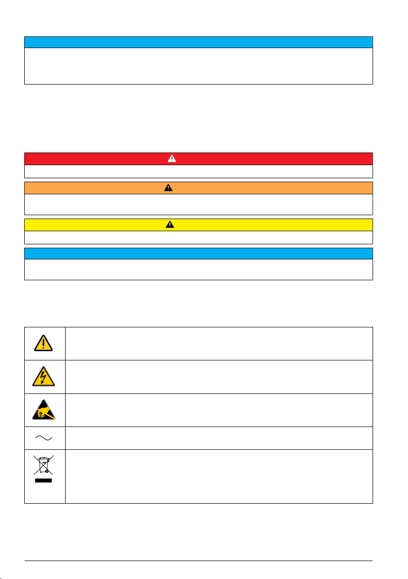
Precautionary labels
Read all labels and tags attached to the product. Personal injury or damage to the product could
occur if not observed. A symbol on the instrument is referenced in the manual with a precautionary
statement.
D A N G E R
W A R N I N G
C A U T I O N
N O T I C E
4 English
This symbol, when noted on a product, indicates a potential hazard which could cause serious
personal injury and/or death. The user should reference this instruction manual for operation and/or
safety information.
This symbol, when noted on a product enclosure or barrier, indicates that a risk of electrical shock
and/or electrocution exists and indicates that only individuals qualified to work with hazardous
voltages should open the enclosure or remove the barrier.
This symbol, when noted on the product, indicates the presence of devices sensitive to electrostatic
discharge and indicates that care must be taken to prevent damage to them.
This symbol, when noted on a product, indicates the instrument is connected to alternate current.
Electrical equipment marked with this symbol may not be disposed of in European public disposal
systems. In conformity with European local and national regulations, European electrical equipment
users must now return old or end-of-life equipment to the manufacturer for disposal at no charge to
the user.
Note: For return for recycling, please contact the equipment producer or supplier for instructions on how to return
end-of-life equipment, producer-supplied electrical accessories, and all auxiliary items for proper disposal.
Page 7
Products marked with this symbol indicates that the product contains toxic or hazardous substances
or elements. The number inside the symbol indicates the environmental protection use period in
years.
Products marked with this symbol indicates that the product conforms to relevant South Korean
EMC standards.
EMC compliance statement (Korea)
Type of equipment Additional information
A 급 기기
( 업무용 방송통신기자재 )
Class A equipment
(Industrial Broadcasting and Communication
Equipment)
이 기기는 업무용 (A 급 ) 전자파적합기기로서 판매자 또
는 사용자는 이 점을 주의하시기 바라며, 가정외의 지역
에서 사용하는 것을 목적으로 합니다.
This equipment meets Industrial (Class A) EMC
requirements. This equipment is for use in industrial
environments only.
Certification
Canadian Radio Interference-Causing Equipment Regulation, IECS-003, Class A:
Supporting test records reside with the manufacturer.
This Class A digital apparatus meets all requirements of the Canadian Interference-Causing
Equipment Regulations.
FCC Part 15, Class "A" Limits
Supporting test records reside with the manufacturer. The device complies with Part 15 of the FCC
Rules. Operation is subject to the following conditions:
1. The equipment may not cause harmful interference.
2. The equipment must accept any interference received, including interference that may cause
undesired operation.
Changes or modifications to this equipment not expressly approved by the party responsible for
compliance could void the user's authority to operate the equipment. This equipment has been tested
and found to comply with the limits for a Class A digital device, pursuant to Part 15 of the FCC rules.
These limits are designed to provide reasonable protection against harmful interference when the
equipment is operated in a commercial environment. This equipment generates, uses and can
radiate radio frequency energy and, if not installed and used in accordance with the instruction
manual, may cause harmful interference to radio communications. Operation of this equipment in a
residential area is likely to cause harmful interference, in which case the user will be required to
correct the interference at their expense. The following techniques can be used to reduce
interference problems:
1. Disconnect the equipment from its power source to verify that it is or is not the source of the
interference.
2. If the equipment is connected to the same outlet as the device experiencing interference, connect
the equipment to a different outlet.
3. Move the equipment away from the device receiving the interference.
4. Reposition the receiving antenna for the device receiving the interference.
5. Try combinations of the above.
Product overview
The controller displays sensor measurements and other data, can transmit analog and digital signals,
and can interact with and control other devices through outputs and relays. Outputs, relays, sensors
and sensor modules are configured and calibrated through the user interface on the front of the
controller.
English
5
Page 8
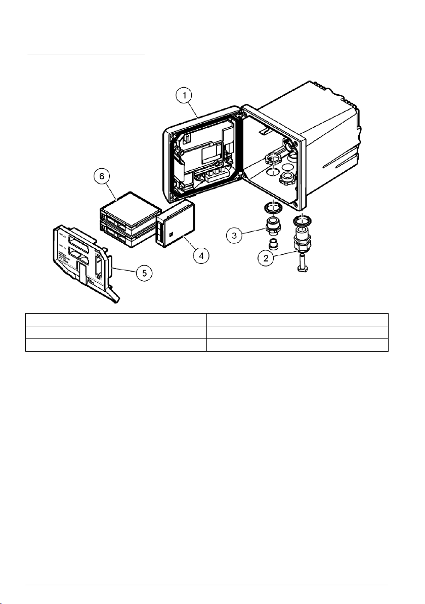
Figure 1 shows the product components. Components may vary according to controller configuration.
Contact the manufacturer if parts are damaged or missing.
Figure 1 System components
1 Controller 4 Network module (optional)
2 Cable gland assembly 5 High-voltage barrier
3 Additional connection fitting 6 Sensor modules (optional)
Sensors and sensor modules
The controller accepts up to a maximum of two sensor modules along with one communication
module. A variety of sensors can be wired to the sensor modules. Sensor wiring information is given
in the specific sensor manuals and in the user instructions for specific modules.
Relays, outputs and signals
The controller has four configurable relay switches and two analog outputs. An optional analog
output module can increase the number of analog outputs to five.
Device scans
With two exceptions, the controller automatically scans for connected devices without user input
when it is powered on. The first exception is when the controller is powered on for the first time
before initial use. The second exception is after the controller configuration settings have been set to
their default values and the controller is powered on. In both cases, the controller first displays the
language, date and time edit screens. After the language, date and time entries are accepted, the
controller performs a device scan.
Controller enclosure
The controller enclosure is NEMA 4X/IP66-rated and has a corrosion-resistant finish designed to
withstand corrosive environmental constituents such as salt spray and hydrogen sulfide. Protection
against environmental damage is strongly recommended for outdoor use.
Note: Units that have the Underwriters Laboratories (UL) certification are intended for indoor use only and do not
have a NEMA 4X/IP66 rating.
Controller mounting options
6
English
Page 9
The controller can be mounted to a panel, to a wall or to a vertical or horizontal pipe. A neoprene
sealing gasket is included and can be used to reduce vibration. The gasket can be used as a
template for panel mounting before the inner gasket component is separated.
Installation
Mounting components and dimensions
C A U T I O N
Personal injury hazard. Only qualified personnel should conduct the tasks described in this section of the manual.
The controller can be installed on a surface, panel or pipe (horizontal or vertical). For mounting
options and instructions, refer to Figure 2, Figure 3 on page 8, Figure 4 on page 9, Figure 5
on page 10 and Figure 6 on page 11.
For horizontal pipe mounts, the mounting feet (Figure 2) must be attached to the mounting bracket in
a vertical position.
For both horizontal and vertical pipe mounts, attach the mounting bracket to the controller as shown
in Figure 5 on page 10.
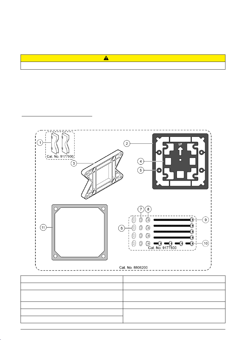
Figure 2 Mounting components
1 Mounting foot (2x) 7 Lock washer, ¼-inch ID (4x)
2 Sealing gasket for panel mount, Neoprene 8 M5 x 0.8 Keps hexnut (4x)
3 Bracket for wall and pipe mounting 9 Pan head screws, M5 x 0.8 x 100mm (4x) (Used for
4 Vibration isolation gasket for pipe mount 10 Pan head screws, M5 x 0.8 x 15 mm (4x)
5 Vibration isolation washer for pipe mount (4x) 11 Bracket for panel mounting
6 Flat washer, ¼-inch ID (4x)
variable diameter pipe mount installations)
English 7
Page 10
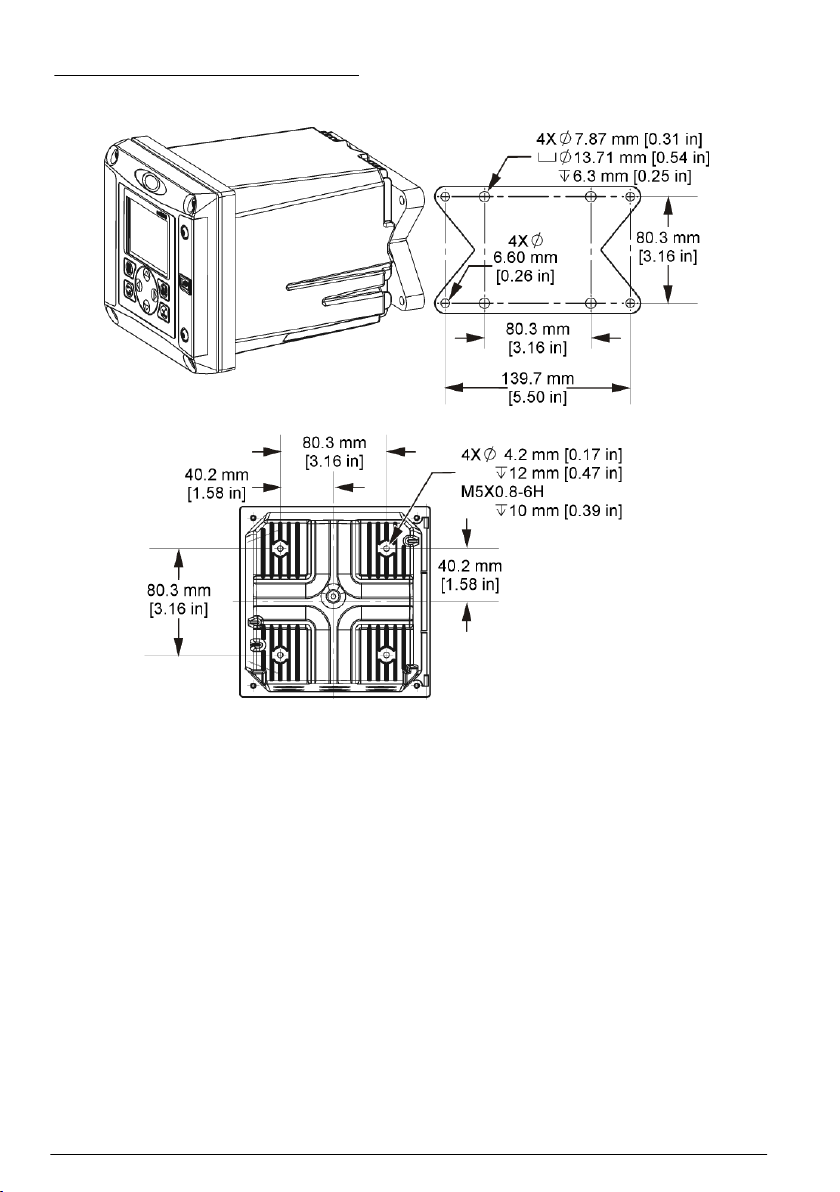
Controller mounting
Figure 3 Surface mounting dimensions
8 English
Page 11
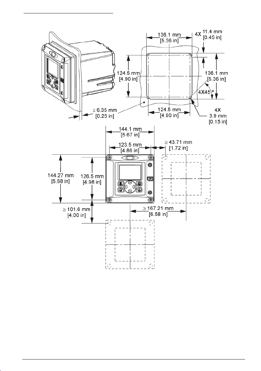
Figure 4 Panel mounting dimensions
Note: If using the bracket for panel mounting (supplied), push the controller through the hole in the panel and then
slide the bracket over the controller on the back side of the panel. Use the four 15 mm pan head screws (supplied)
to attach the bracket to the controller and secure the controller to the panel.
English
9
Page 12
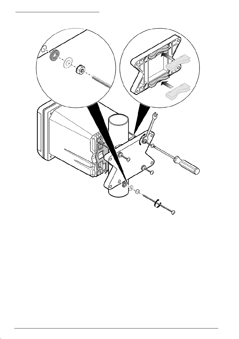
Figure 5 Pipe mounting (vertical pipe)
10 English
Page 13
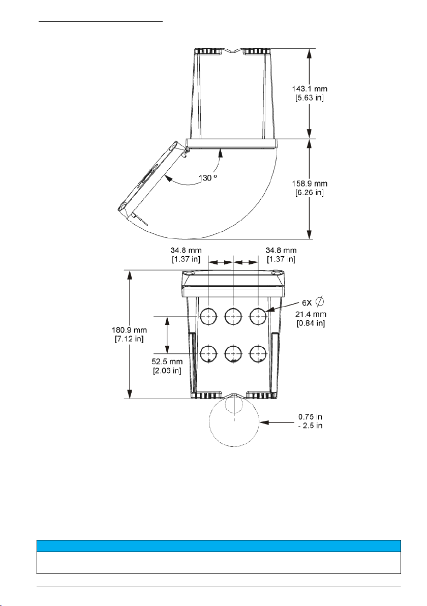
Figure 6 Top and bottom views
High-voltage barrier
High-voltage wiring for the controller is located behind the high-voltage barrier in the controller
enclosure. The barrier must remain in place except when installing modules or when a qualified
installation technician is wiring for power, alarms, outputs or relays. Do not remove the barrier while
power is applied to the controller.
Electrostatic discharge (ESD) considerations
N O T I C E
Potential Instrument Damage. Delicate internal electronic components can be damaged by static electricity,
resulting in degraded performance or eventual failure.
English 11
Page 14
Refer to the steps in this procedure to prevent ESD damage to the instrument:
• Touch an earth-grounded metal surface such as the chassis of an instrument, a metal conduit or
pipe to discharge static electricity from the body.
• Avoid excessive movement. Transport static-sensitive components in anti-static containers or
packages.
• Wear a wrist strap connected by a wire to earth ground.
• Work in a static-safe area with anti-static floor pads and work bench pads.
Wiring overview
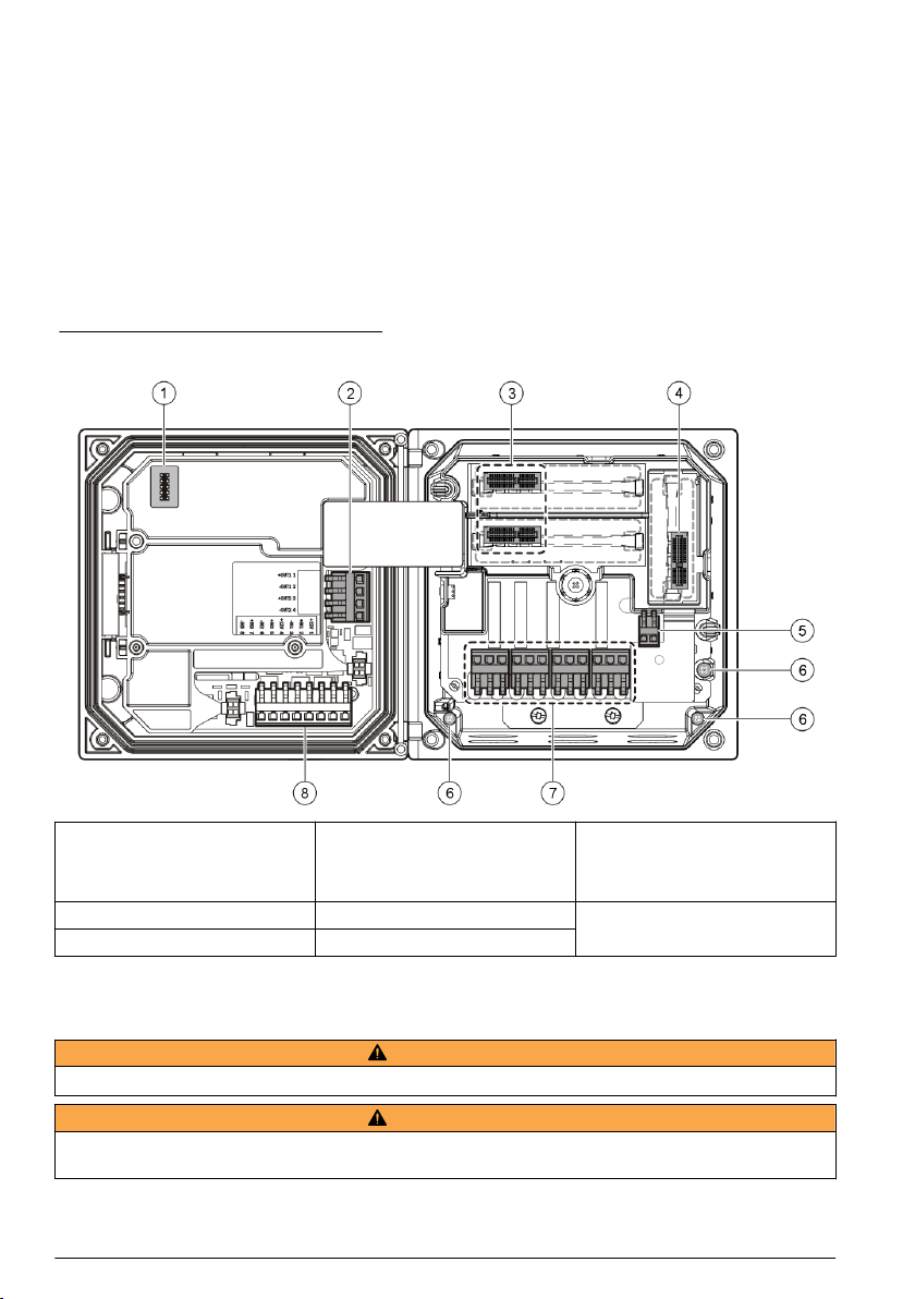
Figure 7 shows an overview of the wiring connections inside the controller with the high voltage
barrier removed. The left side of the figure shows the back side of the controller cover.
Note: Remove connector caps from the connectors before module installation.
Figure 7 Wiring connections overview
1 Service cable connection 4 Communication module
2 4-20 mA output
3 Sensor module connector 6 Ground terminals
1
Terminals can be removed for improved access.
1
connector (e.g., Modbus,
Profibus, optional 4-20 mA
module, etc.)
5 AC and DC power connector
7 Relay connections
1
8 Discrete input wiring connector
1
Wiring for power
W A R N I N G
Potential Electrocution Hazard. Always disconnect power to the instrument when making electrical connections.
Potential Electrocution Hazard. If this equipment is used outdoors or in potentially wet locations, a Ground Fault
Interrupt device must be used for connecting the equipment to its mains power source.
12 English
W A R N I N G
1
Page 15
D A N G E R
Electrocution Hazard. Do not connect AC power to a 24 VDC powered model.
Potential Electrocution Hazard. A protective earth (PE) ground connection is required for both 100-240 VAC and
24 VDC wiring applications. Failure to connect a good PE ground connection can result in shock hazards and
poor performance due to electromagnetic interferences. ALWAYS connect a good PE ground to the controller
terminal.
Install the device in a location and position that gives easy access to the disconnect device and its operation.
W A R N I N G
N O T I C E
The controller can be purchased as either a 100-240 VAC powered model or a 24 VDC powered
model. Follow the appropriate wiring instructions for the purchased model.
The controller can be wired for line power by hard-wiring in conduit or wiring to a power cord.
Regardless of the wire used, the connections are made at the same terminals. A local disconnect
designed to meet local electrical code is required and must be identified for all types of installation. In
hard-wired applications, the power and safety ground service drops for the instrument must be 18 to
12 AWG.
Notes:
• The voltage barrier must be removed before making any electrical connections. After making all
connections, replace the voltage barrier before closing the controller cover.
• A sealing type cable gland and a power cord less than 3 meters (10 feet) in length with three 18gauge conductors (including a safety ground wire) can be used to maintain the NEMA
4X/IP66 environmental rating.
• Controllers can be ordered with AC power cords pre-installed. Additional power cords may also be
ordered.
• The DC power source that supplies power to the 24 VDC powered controller must maintain
voltage regulation within the specified 24 VDC-15% +20% voltage limits. The DC power source
must also provide adequate protection against surges and line transients.
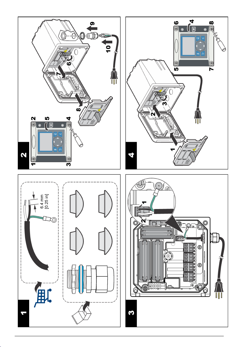
Wiring procedure
Follow the numbered steps and Table 1 or Table 2 to wire the controller for power. Insert each wire
into the appropriate terminal until the insulation is seated against the connector with no bare wire
exposed. Tug gently after insertion to make a secure connection. Seal any unused openings in the
controller box with conduit opening sealing plugs.
Table 1 AC power wiring information (AC powered models only)
Terminal Description Color—N. America Color—EU
1 Hot (L1) Black Brown
2 Neutral (L2) White Blue
— Protective earth (PE) Ground lug Green Green and yellow
Table 2 DC power wiring information (DC powered models only)
Terminal Description Color—N. America Color—EU
1 +24 VDC Red Red
2 24 VDC return Black Black
— Protective earth (PE) Ground lug Green Green and yellow
English 13
Page 16
14 English
Page 17

Alarms and relays
The controller is equipped with four unpowered, single pole relays rated 100-250 VAC, 50/60 Hz,
5 amp resistive maximum. Contacts are rated 250 VAC, 5 amp resistive maximum for the AC
powered controller and 24 VDC, 5A resistive maximum for the DC powered controller. The relays are
not rated for inductive loads.
Wiring relays
W A R N I N G
Potential Electrocution Hazard. Always disconnect power to the instrument when making electrical connections.
Potential fire hazard. The relay contacts are rated 5A and are not fused. External loads connected to the relays
must have current limiting devices provided to limit current to < 5 A.
Potential fire hazard. Do not daisy-chain the common relay connections or jumper wire from the mains power
connection inside the instrument.
Potential electrocution hazard. In order to maintain the NEMA/IP environmental ratings of the enclosure, use only
conduit fittings and cable glands rated for at least NEMA 4X/IP66 to route cables in to the instrument.
AC line (100—250 V) powered controllers
Potential electrocution hazard. AC mains powered controllers (115 V–230 V) are designed for relay connections
to AC mains circuits (i.e. voltages greater than 16 V-RMS, 22.6 V-PEAK or 35 VDC).
The wiring compartment is not designed for voltage connections in excess of 250 VAC.
24 VDC powered controllers
Potential electrocution hazard. 24 V powered controllers are designed for relay connections to low voltage circuits
(i.e. voltages less than 16 V-RMS, 22.6 V-PEAK or 35 VDC).
The 24 VDC controller relays are designed for connection to LOW voltage circuits (i.e., voltages less
than 30 V-RMS, 42.2 V-PEAK or 60 VDC). The wiring compartment is not designed for voltage
connections above these levels.
The relay connector accepts 18-12 AWG wire (as determined by load application). Wire gauge less
than 18 AWG is not recommended.
The Normally Open (NO) and Common (COM) relay contacts will be connected when an alarm or
other condition is active. The Normally Closed (NC) and Common relay contacts will be connected
when an alarm or other condition is inactive (unless the Fail Safe is set to Yes) or when power is
removed from the controller.
Most relay connections use either the NO and COM terminals or the NC and COM terminals. The
numbered installation steps show connection to the NO and COM terminals.
W A R N I N G
W A R N I N G
W A R N I N G
W A R N I N G
W A R N I N G
English
15
Page 18

16 English
Page 19

Analog output connections
W A R N I N G
Potential Electrocution Hazard. Always disconnect power to the instrument when making electrical connections.
Potential electrocution hazard. In order to maintain the NEMA/IP environmental ratings of the enclosure, use only
conduit fittings and cable glands rated for at least NEMA 4X/IP66 to route cables in to the instrument.
Two isolated analog outputs are provided. Such outputs are commonly used for analog signaling or
to control other external devices. Make wiring connections to the controller as shown in Figure 8 and
Table 3.
Note: Figure 8 shows the back of the controller cover and not the inside of the main controller compartment.
Figure 8 Analog output connections
W A R N I N G
Table 3 Output connections
Recorder wires Circuit board position
Output 2- 4
Output 2+ 3
Output 1- 2
Output 1+ 1
1. Open the controller cover.
2. Feed the wires through the cable gland.
3. Adjust the wire as necessary and tighten the cable gland.
4. Make connections with twisted-pair shielded wire and connect the shield at the controlled
component end or at the control loop end.
• Do not connect the shield at both ends of the cable.
• Use of non-shielded cable may result in radio frequency emission or susceptibility levels higher
than allowed.
• Maximum loop resistance is 500 ohm.
5. Close the controller cover and tighten the cover screws.
6. Configure outputs in the controller.
English
17
Page 20

Discrete input wiring connections
W A R N I N G
Potential Electrocution Hazard. Always disconnect power to the instrument when making electrical connections.
Potential electrocution hazard. In order to maintain the NEMA/IP environmental ratings of the enclosure, use only
conduit fittings and cable glands rated for at least NEMA 4X/IP66 to route cables in to the instrument.
Three discrete inputs are provided for switch closure inputs or logic level voltage inputs. Make wiring
connections and configure jumper settings to the controller as shown in Figure 9, Table 4 and
Figure 10.
Note: Figure 9 shows the back of the controller cover and not the inside of the main controller compartment.
Figure 9 Discrete input wiring connections
W A R N I N G
18 English
Table 4 Input connections
Discrete inputs Connector position - Switch input Connector position - Voltage
input
Input 1+ 3 2
Input 1- 2 3
Input 2+ 6 5
Input 2- 5 6
Input 3+ 8 7
Input 3- 7 8
Page 21

Figure 10 Jumper settings
1 Input 1 configuration jumpers 3 Input 3 configuration jumpers 5 Jumpers positioned to the right
2 Input 2 configuration jumpers 4 Jumpers positioned to the left for
switch inputs
for voltage inputs
1. Open the controller cover.
2. Feed the wires through the cable gland.
3. Adjust the wire as necessary and tighten the cable gland.
4. The jumpers are positioned immediately behind the connector. Remove the connector for
improved access to the jumpers and configure the jumper settings according to the type of input
as shown in Figure 10.
5. Close the controller cover and tighten the cover screws.
6. Configure inputs in the controller.
Note: In switch input mode the controller supplies 12 volts to the switch and is not isolated from the controller. In
voltage input mode the inputs are isolated from the controller (user input voltage from 0 to 30 volts).
Connect the optional digital communication output
The manufacturer supports Modbus RS485, Modbus RS232 and Profibus DPV1 communication
protocols. The optional digital output module is installed in the location indicated by item 4 in Figure 7
on page 12. Refer to the manual supplied with the network module for more details.
For information about Modbus registers, refer to http://www.hach-lange.com or http://www.hach.com.
Install a Secure Digital (SD) memory card
For instructions on how to install an SD card in the controller, refer to Figure 11. Information on how
to use the SD memory card can be found in Using the secure digital memory (SD) card
on page 39.
To remove an SD card, push down on the edge of the card and release, then pull the card up and out
of the slot. After the card is removed, close the slot cover and tighten the cover screws.
English
19
Page 22

Figure 11 SD card installation
User interface and navigation
User interface
The keypad has four menu keys and four directional keys as shown in Figure 12.
20 English
Page 23

Figure 12 Keypad and front panel overview
1 Instrument display 5 back key. Moves back one level in the menu
2 Cover for secure digital memory card slot 6 menu key. Moves to the Settings Menu from other
3 home key. Moves to the Main Measurement screen
from other screens and submenus. On the graphical
measurement screen can be used to change the
graph settings.
4 enter key. Accepts input values, updates, or
displayed menu options. On the measurement
screen can be used to display diagnostic
information.
structure.
screens and submenus.
7 Directional keys. Used to navigate through the
measurement screens, menus, change settings,
and increment or decrement digits.
Inputs and outputs are set up and configured through the front panel using the keypad and display
screen. This user interface is used to set up and configure inputs and outputs, create log information
and calculated values, and calibrate sensors. The SD interface can be used to save logs and update
software.
Display
Figure 13 shows an example of the main measurement screen with a DO sensor connected to the
controller.
English
21
Page 24

Figure 13 Example of Main Measurement screen
1 Home screen icon 7 Warning status bar
2 Sensor name 8 Date
3 SD Memory card icon 9 Analog output values
4 Relay status indicator 10 Time
5 Measurement value 11 Progress bar
6 Measurement unit 12 Measurement parameter
Table 5 Icon descriptions
Icon Description
Home screen The icon may vary depending on the screen or menu being displayed. For example, if an SD
SD memory
card
Warning A warning icon consists of an exclamation point within a triangle. Warning icons appear on the
Error An error icon consists of an exclamation point within a circle. When an error occurs, the error
card is installed, an SD card icon appears here when the user is in the SD Card Setup menu.
This icon appears only if an SD card is in the reader slot. When a user is in the SD Card Setup
menu, this icon appears in the upper left corner.
right of the main display below the measurement value. Push the enter key then select the
device to view any problems associated with that device. The warning icon will no longer be
displayed once all problems have been corrected or acknowledged.
icon and the measurement screen flash alternately in the main display. To view errors, push the
menu key and select DIAGNOSTICS. Then select the device to view any problems associated
with that device.
Additional display formats
• From the main measurement screen push the up and down arrow keys to switch between
measurement parameters
• From the main measurement screen push the right arrow key to switch to a split display of up to
4 measurement parameters. Push the right arrow key to include additional measurements. Push
the left arrow key as needed to return to the main measurement screen
• From the main measurement screen push the left arrow key to switch to the graphical display (see
Graphical display on page 23 to define the parameters). Push the up and down arrow keys to
switch measurement graphs
22
English
Page 25

Graphical display
The graph shows concentration and temperature measurements for each channel in use. The graph
supplies easy monitoring of trends and shows changes in the process.
1. From the graphical display screen use the up and down arrow keys to select a graph and push
the home key.
2. Select an option:
Option Description
MEASUREMENT VALUE Set the measurement value for the selected channel. Select between AUTO
DATE & TIME RANGE Select the date and time range from the available options.
SCALE and MANUALLY SCALE. For manual scaling enter the minimum and
maximum measurement values.
System startup
When initially powered up, the LANGUAGE, DATE FORMAT and DATE/TIME screens appear in
order. After these options are set, the controller performs a device scan and displays the message
SCANNING FOR DEVICES. PLEASE WAIT... If a new device is found, the controller performs an
installation process before displaying a main measurement screen.
If the scan finds previously installed devices without configuration changes, the main measurement
screen of the device in the number one position appears immediately after the scan is complete.
If a device has been removed from the controller or is not found during the next power-cycled or
menu-driven scan, the controller displays a DEVICE MISSING message and prompts to delete the
missing device.
If no sensor is connected to an installed analog module, the controller will indicate an error. If devices
are connected but not found by the controller, refer to the Troubleshooting section of this manual.
Set the language, date and time for the first time
The controller displays the language, date and time edit screens when the controller is powered on
for the first time, and when it is powered on after the configuration settings have been set to their
default values.
After the language, date and time options are set for the first time, update the options as necessary
through the setup menu.
1. In the LANGUAGE screen, highlight a language in the options list and push the enter key.
English is the default language for the controller.
2. In the DATE FORMAT screen, highlight a format and push the enter key.
3. In the DATE/TIME screen, push the right or left arrow keys to highlight a field, then push the up
and down arrow keys to update the value in the field. Update the other fields as necessary.
4. Push the enter key. The changes are saved and the controller performs a start-up scan for
devices. If connected devices are found, the controller displays the main measurement screen for
the device in the number one position. If the controller fails to find connected devices, refer to the
Troubleshooting section of this manual.
Controller configuration information
General information about configuration options is listed in the table.
1. Push the menu key and select Polymetron 9500 SETUP.
Option Description
SECURITY SETUP Sets the passcode preferences.
OUTPUT SETUP Configures the controller analog outputs.
English 23
Page 26

Option Description
RELAY SETUP Configures the controller relays.
DISPLAY SETUP Configures the controller display.
ADJUST ORDER—View and modify the measurement display order.
• SEE CURRENT ORDER—View the current display order
• ADD MEASUREMENTS—Add selected measurements to the display
• REMOVE MEASUREMENTS—Remove selected measurements from the
display
• REORDER LIST—Select one or more measurements and change their order
in the display
• SEE DEFAULT ORDER—View the default display order
• SET TO DEFAULT—Set the display order to the default configuration
Note: Some of the above will not be available if no adjustment is possible for that
option (e.g. REORDER LIST and REMOVE MEASUREMENTS will not be
available if only one measurement is selected for display).
DISPLAY CONTRAST—Adjusts the contrast of the controller display.
EDIT NAME—Assigns a name to the controller.
SET DATE/TIME Sets the controller time and date.
DATALOG SETUP Configures data logging options. Available only if CALCULATION has been
MANAGE DATA Select the device from the list of installed components and then select VIEW
ERROR HOLD MODE HOLD OUTPUTS—Holds outputs at last known value when controller loses
CALCULATION Configures the controller math function.
Poly
9500 INFORMATION
setup.
DATA LOG or VIEW EVENT LOG depending on the type of log entry to view.
Specify the selection period to list all log entries matching the selection criteria.
Push the up and down arrows to select an entry and then push enter to view
more details.
communication with the sensor.
TRANSFER OUTPUTS—Switches to transfer mode when controller loses
communication with the sensor. Outputs transfer to a pre-defined value.
SET VARIABLE X—Selects the sensor for the x variable.
SET PARAMETER X—Selects the sensor measurement for the x variable.
SET VARIABLE Y—Selects the sensor for the y variable.
SET PARAMETER Y—Selects the sensor measurement for the y variable.
SET FORMULA—Select the math function to implement:
• None—Disables the math function
• X-Y—Subtraction function
• X+Y—Addition function
• X/Y—Division function
• [X/Y]%—Percentage function
• [X+Y]/2—Average function
• [X*Y]—Multiplication function
• [X-Y]%/X—Difference function
DISPLAY FORMAT—Selects the number of digits and decimal points.
SET UNITS—Selects the units for the calculated reading.
SET PARAMETER—Selects the parameter for the calculated reading.
Displays information about the controller including serial number and software
versions.
24 English
Page 27

Option Description
DISCRETE INPUT
SETUP
LANGUAGE Assigns the language used in the controller.
2. Select an option and push enter to activate the menu item.
Configures three discrete input channels.
Advanced operation
Security setup
Enable or disable the pass code
By default the pass code option is disabled and all configuration settings and calibrations can be
changed. When the pass code function is enabled, access to a number of menus and menu options
will require a pass code.
1. Push the menu key and select Polymetron 9500 SETUP>SECURITY SETUP>SET PASS CODE.
2. Select DISABLED or ENABLED and push enter.
3. Push the home key to enable the new security setting.
Edit the pass code
The pass code is factory set to 9500. The EDIT PASS CODE menu option appears in the SECURITY
SETUP menu only after the pass code feature is enabled and a valid pass code has been entered.
A pass code consists of up to six upper or lower-case alpha, numeric and special characters. Pass
codes are case-sensitive.
To edit the pass code:
1. Make sure the pass code is enabled. Refer to Enable or disable the pass code on page 25 for
information on how to enable the pass code.
2. Push the menu key and select Polymetron 9500 SETUP>SECURITY SETUP.
3. Use the arrow keys to enter the current valid pass code and push enter.
4. Select EDIT PASS CODE and push enter.
5. Use the arrow keys to edit the pass code and push enter.
6. Push the home key to save the new pass code.
Configure a 4-20 mA input module
An analog module must be installed in the controller.
1. Determine what output the connected device is using (0-20 mA or 4-20 mA). This information will
be used to set the scale.
2. Determine what the 20 mA value is equal to (e.g. 100 psi).
3. Determine what the low end (0 or 4 mA) value is equal to (e.g. 10 psi). This information will be
used to set the display range.
4. Push the menu key and select SENSOR SETUP>CONFIGURE.
5. Update the options.
a. Highlight an option and push enter.
b. Make a selection or update the entries.
c. Push enter to save the changes.
Option Description
EDIT NAME Edits the module name
English 25
Page 28

Option Description
EDIT UNITS Edits the measurement units
EDIT PARAMETER Edits the parameter name
DISPLAY RANGE
For the 0-20 mA scale:
• Set the 20 mA value
• Set the 0 mA value
For the 4-20 mA scale:
• Set the 20 mA value
• Set the 4 mA value
Sets the values used for the selected scale (0-20 mA
or 4-20 mA)
SIGNAL AVERAGE Sets how often signals are averaged. Higher values
SET RESOLUTION—
X.XXX, XX.XX, XXX.X, XXXX
SELECT SCALE—
4-20 mA or 0-20 mA
LOG SETUP—5 sec, 30 sec, 1 min, 2 min, 5 min,
10 min, 15 min, 30 min, 60 min
RESET DEFAULTS—Push enter to reset
configuration settings or push the back key to
cancel.
produce a smoother signal but increase the time it
takes for a signal to respond to a change in the
process value.
Sets the number of decimal places used in the display.
Sets scale used for the 4-20 mA input
Sets how often data is logged to the internal controller
memory.
Resets configuration settings to the default values.
Configure a 4-20 mA output module
The NETWORK SETUP option appears in the Settings Menu only if an analog output module or
other network module such as Modbus or Profibus is installed in the controller.
Outputs for analog output modules are set at 4-20 mA. Outputs can be assigned to represent a
measured parameter such as pH, temperature, flow or calculated values.
For configuration information refer to the manual for the output module installed.
Configure the controller analog outputs
The controller analog outputs can be assigned to represent the measured parameter or secondary
measurements such as temperature and calculations.
1. Push the menu key and select Polymetron 9500 SETUP>OUTPUT SETUP.
2. Select OUTPUT 1 or OUTPUT 2.
3. Choose SELECT SOURCE and select a source from the list. Typically the source is one of the
sensors attached to the system. If an analog input card is installed, the analog input may be used
as a source.
4. From the OUTPUT SETUP menu, choose SET PARAMETER and choose an option from the list.
Parameters will vary depending on the type of sensors installed.
5. From the OUTPUT SETUP menu, select SET FUNCTION and choose a function. Further setup
options will vary depending on which function is chosen.
Option Description
LINEAR CONTROL Signal is linearly dependent on the process value.
PID CONTROL Signal works as a PID (Proportional, Integral, Derivative) controller.
26 English
Page 29

Option Description
LOGARITHMIC Signal is represented logarithmically within the process variable range.
BILINEAR Signal is represented as two linear segments within the process variable range.
6. From the OUTPUT SETUP menu, select ACTIVATION. Use the information in the table below the
chosen function to configure the options.
7. If TRANSFER is or will be selected as the ERROR HOLD MODE, or if the transfer will be used
during calibration or other functions within the sensor menu, select SET TRANSFER from the
OUTPUT SETUP menu and enter the transfer value.
8. From the OUTPUT SETUP menu, select SET FILTER and enter the filter value.
9. From the OUTPUT SETUP menu, select SCALE and choose the scale (0-20 mA or 4-20 mA).
• Linear control
Option Description
SET LOW VALUE Sets the low endpoint of the process variable range.
SET HIGH VALUE Sets the high endpoint of the process variable range.
• PID control
Option Description
SET MODE AUTO—the signal is automatically controlled by the algorithm within the analyzer using
PHASE The direction in which the signal responds to process change.
SET SETPOINT Creates a desired control point of process.
PROP BAND A function of the difference between the measured signal and the desired setpoint.
INTEGRAL The period of time from the injection point of a reagent to contact with the measuring
DERIVATIVE Used to compensate for the 2nd order effects of the process. The majority of applications
TRANSIT TIME Stops all PID control for a selected period of time as the sample travels from the control
proportional, integral, and derivative inputs.
MANUAL— the signal is controlled by the user through manual adjustment of the %
change value. This option is shown as MANUAL OUTPUT after the manual set mode is
selected.
DIRECT—signal increases as the process increases.
REVERSE—signal increases as process decreases.
device.
can be controlled without the use of the derivative setting.
pump to the measurement sensor.
• Logarithmic
Option Description
SET 50% VALUE Sets the value corresponding to 50% of the process variable range.
SET HIGH VALUE Sets the upper value of the process variable range.
• Bilinear
Option Description
SET LOW VALUE Sets the low endpoint value of the process variable range.
SET HIGH VALUE Sets the high endpoint value of the process variable range.
English 27
Page 30

Option Description
SET KNEE POINT VALUE Sets the value at which the process variable range divides into another linear
SET KNEE POINT CURRENT Sets the value of the current at the knee point value.
segment.
Logarithmic output mode
Figure 14 shows in graph form the operation of the logarithmic output mode.
Figure 14 Logarithmic output
1 Output current axis 4 50% value 7 Maximum output current
2 Source value axis 5 Minimum output current
(0-4 mA)
3 High value 6 50% output current
(20 mA)
28 English
Page 31

Bilinear output mode
Figure 15 shows in graph form the operation of the bilinear output mode.
Figure 15 Bilinear output
1 Output current axis 4 Knee point value 7 Knee point current
2 Source value axis 5 Low value 8 Maximum output current
3 High value 6 Minimum output current
(0-4 mA)
(20 mA)
Configure relays
The Normally Open (NO) and Common (COM) relay contacts will be connected when an alarm or
other condition is active. The Normally Closed (NC) and Common relay contacts will be connected
when an alarm or other condition is inactive (unless the FAIL SAFE is set to YES), or when power is
removed from the controller. To select a menu option, highlight the option and push enter.
1. Push the menu key and select Polymetron 9500 SETUP>RELAY SETUP.
2. Select a relay from the list.
3. From the RELAY SETUP menu, choose SELECT SOURCE and push enter. Normally, a source
is one of the sensors attached to the system, but the controller can also function as a source. If
an analog input module is installed, the source may be the analog input.
4. From the RELAY SETUP menu, select SET PARAMETER and choose from the list of
parameters. The list of parameter options will vary with the type of attached sensor.
5. From the RELAY SETUP menu, select SET FUNCTION and choose from the list. Further setup
will depend on the function chosen.
Option Description
SCHEDULER (available if the
controller is selected as the
relay source)
ALARM Relay activates when upper or lower alarm value is exceeded
FEEDER CONTROL Relay indicates if a process value exceeds or falls below a setpoint
EVENT CONTROL Relay toggles if a process value reaches an upper or lower limit
Relay switches at certain times independently of any process value
English 29
Page 32

Option Description
PWM CONTROL Relay uses a PWM (Pulse Width Modulation) control depending on a
FREQ CONTROL Relay switches with a frequency depending on a process value
WARNING Relay indicates warning and error conditions in sensors
process value
6. From the RELAY SETUP menu, select SET TRANSFER and choose ACTIVE or INACTIVE.
7. From the RELAY SETUP menu, select FAIL SAFE and choose YES or NO.
8. From the RELAY SETUP menu, select ACTIVATION. The activation options for the selected
function appear.
9. Test the relay function to make sure it is properly energizing the connected device. To do relay
testing, Push the menu key and select TEST/MAINT>TEST RELAY.
• Scheduler function (refer to Figure 16)
Option Description
HOLD OUTPUTS Holds outputs in the present ON or OFF state
RUN DAYS Sets the weekday(s) that the relay operates.
START TIME Sets the start time.
INTERVAL Sets the time between activation cycles (default value: 5 min).
DURATION Sets the period of time the relay is energized (default value: 30 sec).
OFF DELAY Sets the time for additional hold/output time after the relay has been turned off.
Figure 16 Scheduler function
1 Duration 3 Interval
2 OFF delay 4 Time (x-axis)
• Alarm function (refer to Figure 17)
Option Description
LOW ALARM Sets the value where the relay will turn on in response to decreasing measured value.
HIGH ALARM Sets the value where the relay will turn on in response to increasing measured value.
For example, if the low alarm is set for 1.0 and the measured value drops to 0.9, the
relay activates.
For example, if the high alarm is set for 1.0 and the measured value increases to 1.1,
the relay activates.
30 English
Page 33

Option Description
LOW DEADBAND Sets the range where the relay remains on after the measured value increases above
HIGH DEADBAND Sets the range where the relay remains on after the measured value decreases below
OFF DELAY Sets a time (0-300 seconds) to delay the relay from normally turning off (default:
ON DELAY Sets a delay time for the relay to turn on (default: 0 seconds).
the low alarm value. For example, if the low alarm is set for 1.0 and the low deadband is
set for 0.5, the relay remains on between 1.0 and 1.5. Default is 5% of the range.
the high alarm value. For example, if the high alarm is set for 4.0 and the high deadband
is set for 0.5, the relay remains on between 3.5 and 4.0. Default is 5% of the range.
0 seconds).
Figure 17 Alarm function
1 High alarm 4 Low alarm 7 Time (x-axis)
2 High deadband 5 ON delay 8 Source (y-axis)
3 Low deadband 6 OFF delay
• Feeder control function (refer to Figure 18 and Figure 19)
Option Description
PHASE Defines the relay status if the process value exceeds the setpoint.
SET SETPOINT Sets the process value at which the relay toggles. The default value is different for each
DEADBAND Sets the area for an amount of change necessary after the relay setpoint is reached in
OVERFEED TIMER Sets a time period for de-activating an active relay if the process setpoint cannot be
HIGH (default)—turns the relay on when the process value exceeds the setpoint.
LOW—turns the relay on when the process value falls below the setpoint.
sensor.
order to satisfy a condition.
reached. Once an overfeed alarm is present, it must be manually reset.
English 31
Page 34

Option Description
OFF DELAY Sets a delay time for the relay to turn off (default: 0 seconds).
ON DELAY Sets a delay time for the relay to turn on (default: 0 seconds).
Figure 18 Feeder control function
1 Deadband (Phase = Low) 4 OFF delay (phase set high) 7 ON delay (phase set high)
2 Deadband (Phase = High) 5 ON delay (phase set low) 8 OFF delay (phase set low)
3 Setpoint 6 Time (x-axis) 9 Source (y-axis)
32 English
Page 35

Figure 19 Feeder control function (phase low, overfeed timer)
1 Deadband 4 Time (x-axis) 7 Source (y-axis)
2 Setpoint 5 ON delay
3 Overfeed timer 6 OFF delay
• Event control function (refer to Figure 20, Figure 21 and Figure 22)
Option Description
SET SETPOINT Sets the value where the relay will turn on.
DEADBAND Sets a hysteresis so the relay will not swing unregulated when the process value
OnMax TIMER Sets the maximum time the relay can stay on independent from the measured value
OffMax TIMER Sets the maximum time the relay can stay off independent from the measured value
OnMin TIMER Sets the minimum time the relay can stay on independent from the measured value
OffMin TIMER Sets the minimum time the relay can stay off independent from the measured value
converges to the setpoint.
(default: + 0 min).
(default: + 0 min).
(default: + 0 min).
(default: + 0 min).
English 33
Page 36

Figure 20 Event control function (no delay)
1 Source (y-axis) 4 Setpoint 7 OnMax-time
2 High alarm 5 Low alarm 8 OffMax-time
3 Deadband 6 Time (x-axis)
Figure 21 Event control function (OnMin timer, OffMin timer)
1 High alarm 4 Low alarm 7 OnMin timer
2 Deadband 5 Time (x-axis) 8 Source (y-axis)
3 Setpoint 6 OffMin timer
34 English
Page 37

Figure 22 Event control function (ON/OFF delay)
1 High alarm 3 ON delay 5 Time (x-axis)
2 Low alarm 4 OFF delay 6 Source (y-axis)
• PWM control function (refer to Figure 23)
Option Description
SET MODE AUTO—the relay output works as a PID controller.
MANUAL—the signal is controlled by the user through manual adjustment of the % change
value. This option is shown as Manual Output after the manual set mode is selected.
PHASE Reverses the leading sign of the control deviation for the PID controller (default:
SET SETPOINT Creates a setpoint value.
DEAD ZONE The range above and below the setpoint. In this set range, the PID controller does not take
PERIOD Sets the cycle duration of the PWM output signal (default: 5 seconds).
MIN WIDTH Sets the minimum PWM ratio (default: 1.0 second).
MAX WIDTH Sets the maximum PWM ratio (default: 4.0 seconds).
PROP BAND Sets the proportional part of the PID controller. The proportional part of the controller
INTEGRAL Sets the integral part of the PID controller (default: 000 minutes). The integration part of the
REVERSE). The phase selects whether the relay will operate at the first part of a cycle
(direct phase) or the second part (reverse phase).
action to change the Pulse Width Modulation On/Off Ratio output signal until the limits of
the dead zone are reached.
supplies an output signal which is linearly dependent to the control deviation. The
proportional part reacts on any changes at the input but starts to oscillate easily if the value
is set high. The proportional part cannot completely compensate for disturbances.
controller supplies an output signal. The output signal increases linearly if the control
deviation is constant. The integration part responds slower than the proportional part and
can completely compensate disturbances. The higher the integration part, the slower it
responds. If the integration part is set too low, it starts to oscillate.
English 35
Page 38

Figure 23 PWM control function (linear mode)
1 High alarm 4 Low alarm 7 Phase
2 Deadband 5 Period 8 Selected source (y-axis)
3 Setpoint 6 Time (x-axis)
• Frequency control function (refer to Figure 24)
Option Description
SET MODE AUTO—The relay works as a PID controller.
MANUAL—the signal is controlled by the user through manual adjustment of the %
change value. This option is shown as MANUAL OUTPUT after the manual set mode is
selected.
PHASE Reverses the leading sign of the control deviation for the PID controller (default:
SET SETPOINT Sets the process value which is controlled by the PID controller.
DEAD ZONE In this set range, the PID controller does not take action to change the output frequency
PULSE WIDTH Sets the cycle duration (0-600 seconds) of the PWM output signal. (default: 0.5 seconds)
MINIMUM
PULSES
MAXIMUM
PULSES
PROP BAND Sets the proportional part of the PID controller. The proportional part of the controller
INTEGRAL Sets the derivative part of the PID controller (default: 000 minutes). The integration part of
REVERSE). The phase selects whether the relay will operate at the first part of a cycle
(direct phase) or the second part (reverse phase).
until within the limits of the dead zone.
The cycle duration is equal to the duty cycle of the output signal.
Sets the minimum number of pulses per minute at which the relay can operate. Range:
0.001–4.000 (default: 1.000)
Sets the maximum number of pulses per minute at which the relay can operate. Range:
0.001–60.000 (default: 04.000). This value cannot be set lower than MINIMUM PULSES
value.
supplies an output signal which is linearly dependent to the control deviation. The
proportional part reacts on any changes at the input but starts to oscillate easily if the
value is set high. The proportional part cannot fully compensate for disturbances.
the controller generates an output signal. The output signal increases linearly if the control
deviation is constant. The integration part responds slower than the proportional part and
can fully compensate disturbances. The higher the integration part, the slower it responds.
If the integration part is set too low, it starts to oscillate.
36 English
Page 39

Figure 24 Frequency control function
1 High limit 4 Low limit 7 Selected source (y-axis)
2 Deadband 5 Cycle duration
3 Setpoint 6 Time (x-axis)
• Warning function
Option Description
WARNING Sets the level for warning activation. Refer to the sensor manual for the numbers for individual
warning messages.
Set up the discrete inputs
Use these inputs to switch closure inputs or logic level voltage inputs.
1. Push the menu key and select Polymetron 9500 SETUP>DISCRETE INPUT SETUP.
2. Select the desired channel (INPUT 1, INPUT 2 or INPUT 3) and push enter.
3. Select a control logic option and push enter.
Option Description
DISABLE This channel is disabled and not used.
ON/HIGH This channel is active when either the switch input is On (or closed), or the logic level voltage
input is at a High level.
OFF/LOW This channel is active when either the switch input is Off (or opened), or the logic level voltage
input is at a Low level.
4. Select a warning option and push enter.
Option Description
OFF An active discrete input does not trigger a device warning.
ON An active discrete input triggers a device warning.
English 37
Page 40

5. Select an output mode option and push enter.
Option Description
ACTIVE Output level continues to represent operating conditions.
HOLD Output level is held static.
TRANSFER Output level moves to a pre-configured value.
6. Select the sensors that will have their outputs (analog and relay) affected when one of the
discrete inputs becomes active. Push enter.
7. Use the arrows to select the ON DELAY value (the duration time delay between the discrete input
activation and the configured response of the controller). Push enter.
8. Use the arrows to select the OFF DELAY value (the duration time delay between the discrete
input de-activation and the configured response of the controller). Push enter.
9. Repeat steps 4–8 for each desired channel.
10. If a discrete input needs to be changed after initially set up:
a. Repeat steps 1–2 and an INPUT SETTINGS menu appears with the following options:
• CONTROL LOGIC
• SET WARNING
• OUTPUT MODE
• ON DELAY
• OFF DELAY
b. Select the desired option and push enter.
c. Make the desired changes and push enter to save the changes and return to the INPUT
SETTINGS menu.
Set up a calculation
Two sensors must be installed in the controller.
1. Push the menu key and select Polymetron 9500 SETUP>CALCULATION.
2. Select a menu option and choose from the displayed list or update the entry.
Option Description
SET VARIABLE X Selects the sensor that corresponds to the variable set as "X".
SET PARAMETER X Selects the measurement type that corresponds to the variable set as "X".
SET VARIABLE Y Selects the sensor that corresponds to the variable set as "Y".
SET PARAMETER Y Selects the measurement type that corresponds to the variable set as "Y".
SET FORMULA NONE, X-Y, X/Y, [X/Y]%, [X+Y]/2, X*Y, [X-Y]%/X.
DISPLAY FORMAT Sets the number of decimal places displayed in a calculation result.
SET UNITS Sets the units of measurement.
SET PARAMETER Assigns the name of the measurement.
3. Push enter to save the selection or setting and return to the CALCULATION menu.
38
English
Page 41

Set the datalog mode and interval
Datalog Setup is available if a calculation has been set up.
1. Push the menu key and select Polymetron 9500 SETUP>DATALOG SETUP.
Option Description
SET MODE Select an option (SNAP SHOT, AVERAGE, MAXIMUM, MINIMUM).
SET INTERVAL Select an interval from the list.
Using the secure digital memory (SD) card
An SD card must be installed in the controller.
• The SD card can be used to update software and firmware and to download event and data logs. If
the SD card is installed while the controller is in the main menu, push the home key and then the
menu key to verify the option is visible. The SD icon will also be visible in the upper status bar of
the main measurement screen when a card is installed.
• Data log files on the SD card are available in XML and binary formats.
• DataCom is used to convert files from binary to CSV format. Refer to the DataCom manual for
more information on how to use the application. For a copy of the DataCom manual, software
updates or other downloadable resources, go to http://www.hach-lange.com or
http://www.hach.com and search DataCom.
Updating software
Notes:
• The controller does not automatically transfer information to or from an SD card.
• When the SD card is put in multiple controllers, each controller has a separate set of folders in the
SD card memory. To make sure software updates are in the correct folder for the controller in use,
it is best to use a separate dedicated SD card for each controller.
1. Push the menu key and select SD CARD SETUP.
2. Select UPGRADE SOFTWARE and push the enter key.
Note: If the UPGRADE SOFTWARE option does not appear, perform the steps in Firmware updates with SD
cards on page 41.
3. Select a device from the list and push the enter key. The list of options includes the controller and
all connected devices that have software placed in the appropriate folder on the SD card.
4. If more than one version of the upgrade software is available, select the version with the highest
number and push the enter key.
5. Push the enter key to begin the software transfer. The display will show "TRANSFERRING
FILES. PLEASE WAIT..." The percentage of completion appears in the bottom left corner of the
display. The upgrade cannot be halted once it has begun.
• When the transfer is successful, the display will show "TRANSFER COMPLETE" along with a
prompt to push enter to restart the controller or to push the back key and exit to the SD CARD
SETUP menu. Controller updates take effect when the controller is restarted. A restart is not
necessary for sensor updates.
• If the transfer is unsuccessful, the display will show "TRANSFER FAILED" and an error
message. Push the enter key to acknowledge the warning and exit out of the menu. Error
messages are different for each sensor. Refer to the applicable sensor manual.
Save data and event logs with SD cards
Notes:
• Data and event logs can be downloaded to an SD card and viewed with any device capable of
reading an SD card.
English
39
Page 42

• Data logs store the measurement data at selected intervals in a packed binary format (.flg file).
• Event logs store a variety of events that occur on the devices such as configuration changes,
alarms, and warning conditions. Event logs are set up during the sensor or module configuration
process. Event logs are stored in a CSV format.
1. Push the menu key and select SD CARD SETUP>SAVE LOGS.
2. If more than one device appears on the screen, all devices are selected by default. To deselect
an item, highlight the selection and push the left arrow key. Select the devices from which logs
will be saved and push the enter key.
3. Select the time period from which logs are to be saved.
Option Description
LAST DAY All logs from the last full 24 hours, starting from 12:00 a.m., and any additional time
LAST WEEK All logs from the last full week (7 days) starting from 12:00 a.m., and any additional time
LAST MONTH All logs from the last full month (30 days) starting from 12:00 a.m., and any additional time
ALL Save all logs in memory.
NEW All logs that are new since the last time logs were saved to the SD card.
remaining on the current day.
remaining on the current day.
remaining on the current day.
4. Push the enter key to confirm the choice, and push the enter key again to begin the file transfers.
5. Allow time for the files to transfer. The display will show TRANSFERRING FILES. PLEASE
WAIT... and the percentage of files transferred. If the transfer is successful, the display will show
"TRANSFER COMPLETE". If the transfer is not successful, the display will show "TRANSFER
FAILED".
6. Push the enter key to return to the SD CARD SETUP menu.
Access data and event log files on the SD card
A PC, a USB or other SD card reader device, Excel 2003 or higher (for XML files) or the DataCom
application (for binary flg files) are necessary to view the event and data logs stored on an SD card.
Data logs have the following structure: Device Name, Device Serial Number, Device Identification,
Data Log, Time Stamp.
Event logs have the following structure: Device Name, Device Serial Number, Device Identification,
Event Log, Time Stamp.
To view data or event log files stored on the SD card:
1. Attach the card reader device to the PC (if necessary) and install the SD card that contains the
files in the reader device.
2. In the SD card directory, open the HACH folder.
3. Select the Logs folder.
4. Select a device folder.
The event and data log files in the folder are shown.
5. To view XML data log files:
a. Make sure the HachDatalog.xsl style sheet exists in the device folder.
b. Open the Excel application.
c. Go to File, Open.
d. Select the data log file.
e. In the Import XML dialog box, select Open the file with the following style sheet applied
and select HachDatalog.xml.
40
English
Page 43

f. Click OK to view the data.
6. To view binary data log (.flg) files:
a. Make sure the device driver (.flg.drv) file exists in the device folder.
b. Open DataCom.
c. In the File Viewer section, click Open.
d. Select the data log file.
The data log file is shown in the box and a comma separated values (csv) file with the same
file name is created. This csv file can be opened in Excel.
Firmware updates with SD cards
The latest firmware updates can be placed on an SD card. The SD card can then be used to update
the controller or device firmware.
A PC and a USB card reader or other device capable of reading an SD card are necessary.
1. Find the zip file at http://www.hach-lange.com or http://www.hach.comand copy it to the PC.
2. Extract file(s) from the zip folder and save them to the SD card.
3. Remove the SD card and update the controller and device firmware. Refer to Updating software
on page 39.
Backup settings to an SD card
Saves the configuration of a device to the SD card.
1. Push the menu key and select SD CARD SETUP>MANAGE CONFIGURATION>BACKUP
SETTINGS.
2. Select the devices to be backed up. All devices are selected by default. To deselect an item,
highlight the selection and push the left arrow key. Push enter to begin the file transfers. If
backup files already exist on the SD card, a confirmation window appears. Select the devices
again and push enter. Wait for the "TRANSFER COMPLETE" message.
3. Push enter again to return to the MANAGE CONFIGURATION menu.
Restore settings to the controller
This menu selection only appears if a (serial number-specific) backup file for the controller or one of
the sensors connected to it exists on the SD Card. This menu selection loads the configuration of a
specific device from the SD card to the same device (serial number-controlled function).
1. Push the menu key and select SD CARD SETUP>MANAGE CONFIGURATION>RESTORE
SETTINGS.
2. Select the device that will be restored. All devices are selected by default. To deselect an item,
highlight the selection and push the left arrow key. Push enter to begin the file transfers.
3. To have the settings take effect immediately, push enter to restart the controller or push the back
key to return to the MANAGE CONFIGURATION menu.
Transfer settings to another device
Allows the configuration settings for a device to be transferred to an SD card and then to another
device of the same type.
1. Push the menu key and select SD CARD SETUP>MANAGE CONFIGURATION>TRANSFER
SETTINGS.
2. Two options appear:
• RETRIEVE SETTINGS
• COPY SETTINGS
English
41
Page 44

3. To retrieve settings from the controller (or a device connected to it) and put the settings on the SD
card:
a. Select RETRIEVE SETTINGS and push enter.
b. Select the devices that contain the information to be transferred. All devices are selected by
default. To deselect an item, highlight the selection and push the left arrow key. Push enter to
begin the file transfers. Wait for the "TRANSFER COMPLETE" message.
c. If files already exist on the SD card, a confirmation window appears. Select the devices again
and push enter. Wait for the "TRANSFER COMPLETE" message.
d. Push enter to return to the MANAGE CONFIGURATION menu.
4. To copy settings from the SD card to a controller (or a device connected to it):
a. Select COPY SETTINGS and push enter.
b. Select the devices on the SD card. All devices are selected by default. To deselect an item,
highlight the selection and push the left arrow key. Push enter to begin the file transfers. Wait
for the "TRANSFER COMPLETE" message.
c. When the transfer is complete, push enter to restart the connected devices.
d. Push enter to restart the controller or push back to return to the MANAGE CONFIGURATION
menu.
Using the service port
The service port is used to download data files from the controller and install new versions of
controller and sensor firmware. To download data and update software, use the service port in
combination with DataCom and a service cable (LZX887).
Using DataCom
When using the service port, it is necessary to use DataCom. DataCom is a PC Application Utility
that downloads data log and event log files from the controller and installed sensors. Files are
downloaded from the controller through the controller service port or they can be placed on a Secure
Digital Memory (SD) card installed in the controller. In addition, DataCom is used to upload software
for the controller and sensors. The DataCom application must be installed on a PC to read the files.
Refer to the DataCom manual for more information on how to use the application. The DataCom
manual, software updates and other downloadable resources are available at http://www.hach-
lange.com or http://www.hach.com.
Update the display language
1. Push the menu key and select Polymetron 9500 SETUP>LANGUAGE to display the list of
language options.
2. Highlight the language to be used for the controller and push enter.
Update the date and time
1. Push the menu key and select Polymetron 9500 SETUP>SET DATE/TIME.
2. Select DATE FORMAT and push enter.
3. Select a format and push enter.
4. Select DATE/TIME and push enter.
5. Update the entries.
a. Use the right and left arrow keys to highlight a field.
b. Use the up and down arrow keys to change the values in the field and push enter.
c. At the end of the date field, push the right arrow to wrap down to the time fields.
d. Use the up and down and arrow keys to update the time fields.
6. Push enter to save the changes.
42
English
Page 45

Maintenance
D A N G E R
Multiple hazards. Only qualified personnel must conduct the tasks described in this section of the document.
Cleaning the controller
D A N G E R
Always remove power from the controller before performing maintenance activities.
Note: Never use flammable or corrosive solvents to clean any part of the controller. Use of these solvents may
degrade the environmental protection of the unit and may void the warranty.
1. Make sure the controller cover is securely closed.
2. Wipe the controller exterior with a cloth dampened with water, or with a mixture of water and mild
detergent.
Fuse replacement
Fuses are not user-serviceable items. The need for fuse replacement in controllers indicates severe
technical failure and is therefore considered to be a service activity. If a blown fuse is suspected,
contact Technical Support.
Battery replacement
The lithium ion backup battery is not user replaceable. Contact Technical Support for replacement.
Troubleshooting
Problem Resolution
Verify current output configuration.
No current output
Incorrect current output
No relay activation
Test current output signal using the Test/Maintenance submenu.
Input a current value and verify the output signal at the controller
connections.
Contact Technical Support.
Verify current output configuration.
Test current output signal using the Test/Maintenance submenu.
Input a current value and verify the output signal at the controller
connections. If the output is incorrect, perform an output
calibration.
Make sure relay connections are secure.
If using an external power source, make sure the relay wiring is
correct.
Make sure the relay configuration is correct.
Test the relay activation through the Test/Maintenance menu.
The relay should energize and de-energize as selected.
Make sure the controller is not in calibration mode and that the
relay is not being held.
Reset the Overfeed Timer to make sure the timer has not
expired.
English 43
Page 46

Problem Resolution
Make sure the SD card is properly oriented. The copper traces
should face toward the controller display.
Make sure the SD card is fully seated in the slot and the spring
lock is engaged.
Secure Digital Memory (SD) card not
recognized by the controller
Information not saving, or not saving properly
to the SD card.
SD card full
Controller cannot find software updates on the
SD card.
Display is lit but shows no characters or
characters are faint or blurry.
Controller will not power up, or powers up
intermittently
Network or sensor module not recognized
Make sure the SD card is properly formatted with a Fat
32 format. The MMC format is not supported. Follow the
instructions of the card manufacturer to format the SD card on a
PC.
Make sure the card is not larger than 32 GB.
Make sure an SD card is being used. Other types of cards (such
as xSD, micro SD, mini SD) will not work properly.
Make sure the SD card is properly formatted with the FAT
32 format. The MMC format is not supported. Follow the
instructions of the card manufacturer to format the SD card on a
PC.
If the SD card has previously been in use, format the card with
the Fat 32 format, install the card in the controller, and try
downloading files.
Try a different SD card.
Read the SD card with a PC or other card reader device. Save
important files and then delete some or all of the files on the SD
card.
Make sure an appropriate folder is created by installing the SD
card in the controller. An update folder will automatically be
created.
Install the SD card on a PC and make sure the software files are
located in the appropriate update folder.
If the same SD card is used with multiple controllers, each
controller will have a separate folder on the system. Make sure
the software updates are in the folder dedicated to the controller
in use.
Adjust the display contrast
Make sure protective film has been removed from display.
Clean the outside of the controller, including the display screen.
Make sure the AC power connections are properly terminated in
the controller.
Make sure the power strip, line power, wall plug are all properly
plugged in.
Contact Technical Support
Make sure the module is properly installed.
Make sure the module selector switch is set to the proper
number.
Remove sensor module and install the module into the second
analog slot. Apply power to the controller and allow the controller
to perform a device scan.
Contact Technical Support.
44 English
Page 47

Problem Resolution
If the sensor and a corresponding module is installed in the
Sensor not recognized
Device Missing error message appears
controller, refer to the instructions supplied with the Network or
Sensor Module.
Contact Technical Support
Perform a Device Scan from the Test/Maintenance menu.
Power cycle the controller
Test and maintenance menu
1. Push the menu key and select TEST/MAINT.
Option Description
SCAN DEVICES Performs a scan for active and missing devices.
OUTPUT CAL
• OUTPUT 1
• OUTPUT 2
HOLD OUTPUTS Sets the value the controller sends to an external system for a defined period of
TEST OUTPUT
• OUTPUT 1
• OUTPUT 2
Lets the user calibrate the 4–20 mA outputs with a 250 ohm resistor in series to
the mA output terminals. The settings for each output are adjusted until the
correct value (4 mA or 20 mA) is supplied.
CAL 4 mA output (Min: 0 Max: 25000)
CAL 20 mA output (Min: 35000 Max: 65533)
time. After the time period, the instrument goes back to reporting real time
values.
ACTIVATION—LAUNCH or RELEASE
SET OUTMODE—HOLD OUTPUTS (default) or TRANSFER OUTPUTS
SET CHANNELS—ALL (default) or select from hardware list
Lets the user select a mA value that is sent by the controller for verification.
Min: 0 mA (default +04.00)
Max: 25.00 mA
STATUS View status of all modules, sensors and relays.
TEST RELAY—A, B, C, D ENERGIZE or DE-ENERGIZE the selected relay.
OVERFEED RESET Resets the overfeed timer.
RESET DEFAULT
CONFIG
RESTART Performs a controller restart.
SIMULATION (only
displays if sensors or
modules are connected)
Resets the controller configuration settings to the default values (language, date
and time, relay function and data output function).
After the SIM VALUE is entered, the controller outputs this value as if it was the
value sent from the sensor. The simulation stops after the user exits the screen.
SELECT SOURCE—
• <Module 1>
• <Module 2>
(footer displays current source selection)
SET PARAMETER—Source measurement type (footer displays current source
selection)
SET SIM VALUE—Use arrow keys to change value (footer displays current
source selection)
English 45
Page 48

Option Description
MODBUS STATS Displays Error and Good count stats for selected port.
• Sensor port 1, 2, 3 or 4
• Network port
• Service port
• Clear stats
SYSTEM DATA Displays the current system current, temperature and voltage data.
Warning and error conditions
Follow the steps below to acknowledge controller warnings.
1. Push the menu key and select DIAGNOSTICS.
2. Select the device (controller, sensor, network card) with the warning or error and push enter.
3. Select the warning, error or event list and push enter.
4. Select YES and push enter to acknowledge the warning.
Note: Errors cannot be acknowledged.
Device scan information
Display message Action
INSTALLING DEVICE... PLEASE WAIT The controller has found a new device. No action is
DEVICE MISSING <device id> A previously installed device has been removed from
necessary. The controller automatically performs an
installation process for the new device and displays the
main measurement screen of the device installed in the
number one position.
the controller or is not detected.
• Push the enter key to continue.
• Push the left arrow key to select or de-select a
missing device.
• Push the enter key to delete the missing device.
The controller will display the main measurement
screen for the device in the number one position.
Note: This message also displays when a device is missing and
a new device has been installed. After the missing device is
deleted, the controller automatically installs the new device and
displays INSTALLING DEVICE... PLEASE WAIT. The controller
then displays the main measurement screen for the device
installed in the number one position.
Replacement parts and accessories
Note: Product and article numbers may vary for some selling regions. Contact the appropriate distributor or refer to
the company website for contact information.
General
Description Item number
4 GB Secure Digital Memory (SD) card 9218100
Controller installation kit 8806200
DataCom cable LZX887
46 English
Page 49

General (continued)
Description Item number
Mounting bracket inserts 9177900
Plug, conduit opening (set of 3) 5868700
Power cord kit, with cable gland, 125 VAC, U.S.-style plug 9202900
Power cord kit, with cable gland, 230 VAC, European-style plug 9203000
Screw driver 6134300
SD card reader 9218200
SD card cover kit for controller 9200900
Screws for controller installation kit 9177800
Cord grip kit (1) 9178000
Sealing washer for cord grip assembly 1033814
UV protection screen 8809200
Weather and sun shield w/ UV protection screen 9220600
Sensor and communication modules
Description Item number
Conductivity module 9013000
Flow module 9012700
4-20 mA input module 9012800
pH and DO module 9012900
4-20 mA output module 9334600
Modbus network module 9013200
Profibus network module YAB104
Profibus M12 connector kit 9178500
Profibus M12 socket (hard wire to quick connector adapter) 9178200
Profibus M12 T-splitter 9178400
English 47
Page 50

48 English
Page 51

Page 52

HACH COMPANY World Headquarters
P.O. Box 389, Loveland, CO 80539-0389 U.S.A.
Tel. (970) 669-3050
(800) 227-4224 (U.S.A. only)
Fax (970) 669-2932
orders@hach.com
www.hach.com
©
Hach Company, 2013.
All rights reserved. Printed in Europe.
HACH LANGE GMBH
Willstätterstraße 11
D-40549 Düsseldorf, Germany
Tel. +49 (0) 2 11 52 88-320
Fax +49 (0) 2 11 52 88-210
info@hach-lange.de
www.hach-lange.de
HACH LANGE Sàrl
6, route de Compois
1222 Vésenaz
SWITZERLAND
Tel. +41 22 594 6400
Fax +41 22 594 6499
 Loading...