

Page 1

Document Number 221=183=000
POLYMETRON 83xx
2 Electrode Conductivity Probes
USER MANUAL
September 2010, Version B
Page 2

Page 3
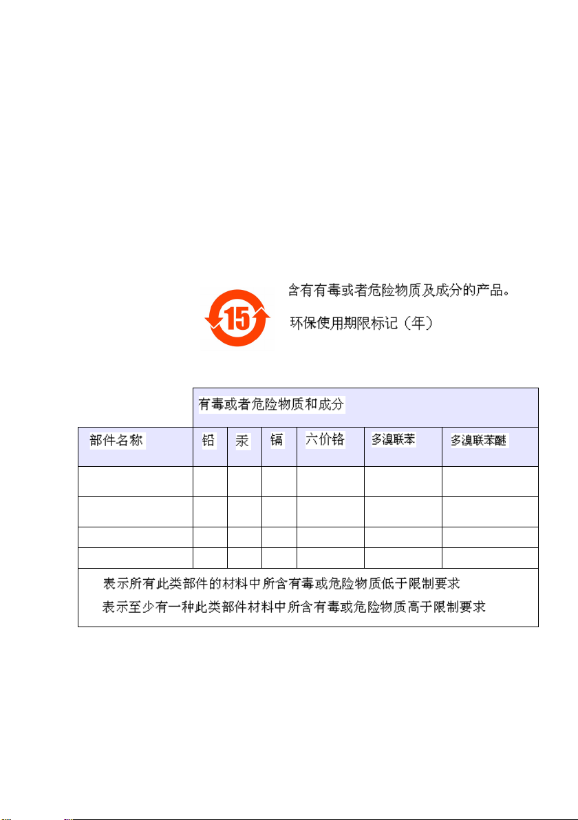
Restriction of hazardous substances (RoHS)
The European Union RoHS Directive and subsequent regulations
introduced in member states and other countries limits the use of six
hazardous substances used in the manufacturing of electrical and
electronic equipment.
Currently, monitoring and control instruments do not fall within the
scope of the RoHS Directive, however Hach Lange has taken the
decision to adopt the recommendations in the Directive as the target
for all future product design and component purchasing.
Note: The following only applies to exports of this product into the
People’s Republic of China.
Plastic sensor
(8310, 8311, 8312)
Stainless steel sensor
(8314, 8394)
Digital sensor PCB O
Glass electrode O
O:
X:
O
O
Page 4

Page 5

2 ELECTRODES CONDUCTIVITY PROBE - INSTRUCTION MANUAL
SUMMARY
1. Overview ................................................................. 5
General.......................................................................................5
Principle of electrolytic conductivity............................................5
Influence of the temperature ......................................................6
2. Technical specifications........................................ 9
Chemical resistance.................................................................10
3. Installation and start-up....................................... 13
Cable connection......................................................................13
Programming of the transmitter................................................14
Probe calibration ......................................................................16
Probe installation......................................................................17
4. Maintenance and cleaning................................... 25
Spares parts.............................................................................27
5. Precautionary Labels........................................... 29
621=183=000 Issue B 09/2010 Page 1
Page 6

Page 7
2 ELECTRODES CONDUCTIVITY PROBE - INSTRUCTION MANUAL
Any use that does not comply with that described in this manual may
lead to risks for the user. Furthermore, this latter cannot change any of
the sensor or transmitter’s components. Only Hach Lange staff, or its
approved representative, is authorised to repair the system and only
components explicitly approved by the manufacturer can be used.
Any attempts to repair the instrument that go against these principles
may cause damage to the equipment or to the person performing the
repairs.
It also cancels the guarantee and may compromise the instrument’s
safety, electrical integrity or EC compliance.
Warning !
621=183=000 Issue B 09/2010 Page 3
Page 8

Page 9

2 ELECTRODES CONDUCTIVITY PROBE - INSTRUCTION MANUAL
1. Overview
General
The probes for which the electrochemical
exchanges take place directly between the
electrode and the solution are called
"contacting" probes or "kohlrausch" probes.
They consist of two conductor electrodes
(chemically inert in relation to the solution),
insulated from each other, in a particular and
known geometrical form (cell constant), on
which an alternating voltage is applied.
Therefore a mechanism of exchange exists at
the interface of the liquid and the electrodes
and only the use of an alternating voltage with
an optimum frequency avoids saturating the
surface of the electrodes (formation of an
insulating layer reducing the flow of current, a
phenomenon known under the term of
"polarisation").
It is the total quantity of ions present in the
solution that is measured and not the type of
ion as such.
Principle of electrolytic conductivity
Ohm’s law specifies that the current circulating
in the dipole is proportional to the difference in
potential and resistance of this dipole:
I = E / R.
621=183=000 Issue B 09/2010 Page 5
Page 10

2 ELECTRODES CONDUCTIVITY PROBE - INSTRUCTION MANUAL
E, potential
R, resistance of the dipole such as:
the resistance of a homogenous
environment depends on the geometry of
the resitivity (characteristic of the material):
R = r. l/S where r = R/K (Ω.cm) where
C=
K
(S.cm-1)
R
K depending solely on the geometry of the
probe is (in the case of the two flat electrodes
face to face) the relation between the distance
separating the electrodes divided by their
surfaces and expressed in cm
I= E/R= C.E/K
-1
.
Influence of the temperature
The conductivity of a solution depends both on
the ionic concentration and the mobility of these
ions (size, weight, charge, viscosity). The
temperature of the solution has an influence on
these two factors (the temperature favours the
dissociation of the molecules and therefore the
ionic concentration, and increases the mobility).
In order to allow the comparison between
measurements made at different temperatures,
this measurement needs to be brought back to
a reference temperature (generally 25 °C).
Page 6 09/2010 621=183=000 Issue B
Page 11

2 ELECTRODES CONDUCTIVITY PROBE - INSTRUCTION MANUAL
= C T [1 + " (T - T
C
Tref
ref
)]-1
: Conductivity compensated to the
C
Tref
reference temperature
C
: Conductivity measured at T
T
T
: Reference temperature
ref
(generally 25°C)
" : Temperature coefficient of the solution
(% / °C)
• For the sufficiently concentrated solutions
(natural waters, process…) the coefficient
is constant and is situated around 2 %.
• For slightly concentrated solutions, the
concentration of H+ protons and hydroxyl
OH- ions (stemming from the weak
dissociation of the water [H+] = [OH-] =
-7
mol/l to 25°C) can no longer be
10
neglected in the presence of the product,
this therefore leads to a non-linear
variation (compensation curve NaCI and
HCI).
621=183=000 Issue B 09/2010 Page 7
Page 12

Page 13

2 ELECTRODES CONDUCTIVITY PROBE - INSTRUCTION MANUAL
2. Technical specifications
Model 8310 and 8315 8311 and 8316 8312 and 8317 8394
Applications : Pure or high purity
K (cm-1) 0.01 0.1 1 0.01
Precision K < 2 % < 2 % < 2 % < 2 %
Measurement
range (9125)
Temperature
response
Pt100 (t 90 %)
Materials in contact
with the liquid:
Temperature max
(°C)
P max (bars) 10 (8310)
Process
connection
waters
0.01 à 200 µS.cm-1 0.1 µS à 2 mS.cm-1 1 µS à 20 mS.cm-1 0.01 à 200 µS.cm-1
< 30 s < 45 s < 3 mn < 45 s
Electropolished
stainless steel +
Psu (8310)
Electropolished
stainless steel +
PES 30 %
glassfiber + viton
(8315)
125 (8310)
150 (8315)
25 (8315)
¾’’NPT ¾’’NPT ¾’’NPT Tri clamp 1.5 et 2’’
Meanly
conductived
solutions
Stainless steel +
Psu (8311)
Stainless steel +
PES 30 %
glassfiber + viton
(8316)
125 (8311)
150 (8316)
10 (8311)
25 (8316)
Worm water,
process
Graphite + Psu
(8312)
Stainless steel +
graphite + viton
(8317)
125 (8312)
150 (8317)
10 (8312)
25 (8317)
Food and
pharmaceutical
industries
(sterilizable)
Electropolished
stainless steel +
PEEK + EPDM
« FDA », Ra < 0.4
150
25
621=183=000 Issue B 09/2010 Page 9
Page 14
2 ELECTRODES CONDUCTIVITY PROBE - INSTRUCTION MANUAL
Chemical resistance
O = yes ; - = no
X = momentarily
°C/% 20 60 100 20 60 100 20 60 100
Sulphuric acid 10 0 X X 0 0 X 0 X X
Hydrochloric acid 1
Citric acid < 25 0 X - 0 - - 0 X Phosphoric acid < 25 0 0 0 0 0 0 0 0 0
Hydrofluoric acid 40 - - - X - - - - Acetic acid 10 0 0 X 0 0 0 X X Citric acid 50 0 0 - 0 0 - 0 0 Potassium hydroxide 50 0 x x - - - x x Sodium hydroxide 10 0 0 X 0 0 X 0 X Ammoniac 10 0 0 X 0 0 X - - Zinc chloride 50 x x x 0 0 0 x x x
Iron chloride 50 - - - 0 0 0 - - Sodium sulphite Sat 0 0 0 0 0 0 0 0 Potassium chloride Sat 0 x x 0 0 0 0 x x
Sodium sulphite Sat 0 0 0 0 0 0 0 0 0
Calcium chloride Sat 0 0 x 0 0 0 0 0 x
Sodium chloride Sat x x x 0 0 0 x x x
Sodium nitrate 50 x x x 0 0 0 x x x
Aluminium chloride Sat - - - 0 0 0 - - Sodium hypochlorite 50 x x x 0 0 x x x x
Ethanol 80 0 x - 0 x - 0 x Cyclohexane - - - - - - - - Toluene - - - - - - - - Trichloroethane - - - - - - - - Water 0 0 0 0 0 0 0 0 0
8310/8311
0 - - - - - 0 0 0 0 0 0 0 - - - -
10
8312
8315/8316
-
Page 10 09/2010 621=1 83=000 Issue B
Page 15

2 ELECTRODES CONDUCTIVITY PROBE - INSTRUCTION MANUAL
O = yes ; - = no
X = momentarily
°C/% 20 60 100 20 60 100
Sulphuric acid 10 0 X X 0 X X
Hydrochloric acid 1
Citric acid < 25 0 X - 0 - Phosphoric acid < 25 0 0 0 0 0 0
Hydrofluoric acid 40 - - - - - Acetic acid 10 0 0 0 X X Citric acid 50 0 0 - 0 0 Potassium hydroxide 50 0 x x - - Sodium hydroxide 10 0 0 X 0 X Ammoniac 10 0 0 X - - Zinc chloride 50 x x x x x X
Iron chloride 50 - - - - - Sodium sulphite Sat 0 0 0 0 0 Potassium chloride Sat 0 x x 0 x X
Sodium sulphite Sat 0 0 0 0 0 0
Calcium chloride Sat 0 0 x 0 0 X
Sodium chloride Sat x x x x x X
Sodium nitrate 50 x x x x x x
Aluminium chloride Sat - - - - - Sodium hypochlorite 50 x x - x x X
Ethanol 80 0 x - 0 x Cyclohexane - - - - - Toluene - - - - - Trichloroethane - - - - - Water 0 0 0 0 0 0
8394 8317
0 - - - - - 0 - - - -
10
-
621=183=000 Issue B 09/2010 Page 11
Page 16

Page 17

2 ELECTRODES CONDUCTIVITY PROBE - INSTRUCTION MANUAL
3. Installation and start-up
Cable connection
WARNING
Connect the cable quickly to avoid any risk
of humidifying the connector
L = 5, 10 or 20 m
L = 5/10 ou 20 m
Figure 3-1 - Connections
1. External shielding
2. Internal shielding
3. Internal electrode
4. External electrode
5. Pt100
6. Pt100
The cable reference :
08319=A=0005/0010/0020 (depending on
length 5, 10 or 20 m) must be connected in
compliance with the following table:
N° Colour Function Transmitter
6 Blue Pt100 TEMP + 14 (19) 10
5 Black Pt100 TEMP - 15 (20) 11
4 Red External electrode OUT 17 (22) 13
3 White
(Yellow tip)
2 White
(Orange tip)
1 White
(red tip)
Internal electrode IN 18 (23) 12
Internal shielding GND 16 (21) 14
External shielding EARTH BOX EARTH BOX EARTH BOX
9125
Transmitter
8920
Transmitter
8925
621=183=000 Issue B 09/2010 Page 13
Page 18

2 ELECTRODES CONDUCTIVITY PROBE - INSTRUCTION MANUAL
Programming of the transmitter
REMARK
To obtained detailed information, please
refer to the operating manuals of our
transmitters.
Setting the type of measurement:
9125: Check that both switches of the
conductivity module have been correctly
configured on K (2 electrodes).
Setting the frequency in function with the
conductivity:
K (cm-1) Low
conductivity
0.01 0.01…0.1 µS 0.1 µS…20 µS 20 µS…200 µS
0.1 0.1….1 µ S 1 µS…200 µS 200µS…2 mS
1 1 … 10 µ S 10 µS…2 mS 2…20 mS
It is preferable, whenever possible, to operate
in the "Average conductivity" zone (and
therefore to choose the type of sensor well).
Average
conductivity
High
conductivity
• « Low conductivity » zone:
Do not combine a long length of cable with
a high measurement frequency, to avoid
provoking a parallel capacitance
(measurement of conductivity too high).
If one uses a long cable (> 20 m), adjust to
a frequency of 70 Hz.
Page 14 09/2010 621=183=000 Issue B
Page 19

2 ELECTRODES CONDUCTIVITY PROBE - INSTRUCTION MANUAL
• « Average conductivity » zone:
No particular precautions in this zone:
choose f = 1 kHz.
• « High conductivity » zone:
When the measurement frequency is low,
the surface of the electrodes will very
quickly saturate (formation of an insulating
layer reducing the flow of current, a
phenomenon known as "polarisation").
Choose f > 1 kHz
REMARK
9125 : select the "automatic frequency"
mode, in order to automatically set the best
frequency according to the measurement
range.
Definition of the cell constant value:
Enter real cell constant value of the probe (this
value is indicated in the certificate, it is
determined with a precision < 2 % in
compliance with ASTM D 1125 and ISO7888
standards).
Definition of the temperature
compensation mode:
Programm the mode of temperature
compensation of the transmitter according to
the characteristics of the process (see & 1,
influence of the temperature).
621=183=000 Issue B 09/2010 Page 15
Page 20

2 ELECTRODES CONDUCTIVITY PROBE - INSTRUCTION MANUAL
Probe calibration
Whenever possible, we advise proceeding in
the following order:
• Temperature calibration
¾ It's an indispensable operation during
the commission for taking into account
the resistivity of the cable and offset
probe Pt100.
¾ Immerse the probe in a solution for
about 10 mn.
¾ Record the temperature of the solution
with a thermometer (precision < ± 0.1°C).
¾ Programm the transmitter in process
calibration mode.
¾ Adjust the value of the temperature read
with that of the thermometer.
• Conductivity calibration
First method (recommended) :
¾ Programm the transmitter in electrical
calibration mode. Choose the resistance
the closest possible to your process
(see table on the following page).
¾ First point: Remove the probe from the
liquid or unscrew the connector (Infinite
resistance, taking into account the
capacity of the cable).
¾ Second point: Connect the resistance
(precision < 0,1 %) of the value
programmed at the IN/OUT terminals of
the conductivity module.
Page 16 09/2010 621=183=000 Issue B
Page 21

2 ELECTRODES CONDUCTIVITY PROBE - INSTRUCTION MANUAL
Conductivity solution :
Resistivity solution :
R connected for K= 0.01 cm-1
R connected for K= 0.1 cm-1 R connected for K= 1 cm-1 -
0.1 µS.cm-1
10 MΩ.cm
100 kΩ 1 kΩ
0.1 MΩ.cm
-1
10 µS.cm
10 kΩ 100 Ω
100 kΩ 1 kΩ 100 Ω
1 mS.cm-1
1 kΩ.cm
10 mS.cm-1
100 Ω.cm
- -
-
- : unadapted measurement
Second method :
¾ Programm the transmitter in "process"
calibration mode.
¾ Make sure that the value recorded is
stabilised before adjusting it with that of
a precision calibration solution
(conductivity close to that of the
process).
Probe installation
On piping:
Entirely immerse the internal electrode in the
process (take into account the dimensions on
the following page in the event of a 90°
installation):
621=183=000 Issue B 09/2010 Page 17
Page 22

2 ELECTRODES CONDUCTIVITY PROBE - INSTRUCTION MANUAL
Figure 3-2 - Dimensions of electrodes
Figure 3-3 - Dimensions of electrodes
Figure 3-4 - Diameters of electrodes
MODEL h max
(mm)
8310/11 40 80 DN40 ou 1.5’’
8312 50 75 DN20 ou ¾’’
8315 28 117 DN90 ou 4’’
8316 28 80 DN50 ou 2’’
8317 28 90 DN75 ou 3’’
8394 21.5 65.5 DN50 ou 2’’
H min
(mm)
D min
(standard piping)
Page 18 09/2010 621=183=000 Issue B
Page 23

2 ELECTRODES CONDUCTIVITY PROBE - INSTRUCTION MANUAL
EXEMPLES OF INSTALLATIONS :
• 8315 :
h > 28 mm
h < 28 mm
Figure 3-5 - Electrode 8315
A Very good installation:
Perfect immersion of the electrode surfaces.
B Correct installation:
Satisfactory immersion of the electrode surfaces.
C Poor installation:
Incomplete immersion of the electrodes, the
conductivity will be too low.
The direction indicates the direction of flow.
REMARK
621=183=000 Issue B 09/2010 Page 19
Page 24

2 ELECTRODES CONDUCTIVITY PROBE - INSTRUCTION MANUAL
• 8394 :
This one installs perfectly in all short reduced
triclamp Tee "3A" Tri-clover® starting from
1.5” (A), and also in short standard bent Ts at
90° "3A" starting from 2” (B).
Figure 3-6 - 8394 electrode
A Very good installation:
Perfect immersion of the electrode surfaces.
B Correct installation:
Satisfactory immersion of the electrode surfaces.
C Poor installation:
Incomplete immersion of the electrodes, the
conductivity will be too low.
The direction indicates the direction of flow.
REMARK
In bypass
The flow-through chambers, are designed not
to retain air bubbles. To encourage the
extraction of the bubbles, use a minimum
flowrate of 20 l/hr (ideally 60 l/hr).
Page 20 09/2010 621=183=000 Issue B
Page 25

2 ELECTRODES CONDUCTIVITY PROBE - INSTRUCTION MANUAL
REMARK
The progressive accumulation of bubbles on
the surface of the probe:
¾ reduces its active surface,
¾ increases the cell constant,
¾ leads to a too low measure of conductivity.
Figure 3-7 - Circulation chamber
A Very good installation:
Perfect immersion of the electrode surfaces.
B Correct installation:
Satisfactory immersion of the electrode surfaces.
C Poor installation:
Incomplete immersion of the electrodes, the
conductivity will be too low.
The direction indicates the direction of flow.
REMARK
621=183=000 Issue B 09/2010 Page 21
Page 26

2 ELECTRODES CONDUCTIVITY PROBE - INSTRUCTION MANUAL
Specifications of flow-through
chamber :
Reference : 08313=A=0001 08318=A=0001
Material: PVC 316 L SS
Tmax (°C) 60 150
Pressure (bar) 10 (at 25°C) 25
Sensor connection ¾’’NPT ¾’’NPT
Process connections (I/O) ¾’’NPT ¼’’NPT
Reference : 08394=A=8200 08394=A=8150
Material: 316 L SS 316 L SS
Tmax (°C) 150 150
Pressure (bar) 25 25
Sensor connection Clamp 2’’ Clamp 1.5’’
Process connections (I/O) ¼’’NPT ¼’’NPT
REMARK
Make sure the NPT fittings are leak free by adding
some waterproof material (PTFE thread seal tape,
sealant compound, etc.) onto the male thread.
Recommended waterproof material :
Flow-through
chamber
08313=A=0001 PTFE thread seal tape PTFE thread seal tape
08318=A=0001 PTFE thread seal tape Loctite 577
08394=A=8200 PTFE thread seal tape Loctite 577
08394=A=8150 PTFE thread seal tape Loctite 577
Sensor
8310/8311/8312
Sensor
8315/8316/8317/8394
Page 22 09/2010 621=183=000 Issue B
Page 27

2 ELECTRODES CONDUCTIVITY PROBE - INSTRUCTION MANUAL
Dimensions :
08313=A=0001 08318=A=0001 08394=A=8200 08394=A=8150
Figure 3-8 - Dimensions of flow-through chamber
621=183=000 Issue B 09/2010 Page 23
Page 28

Page 29

2 ELECTRODES CONDUCTIVITY PROBE - INSTRUCTION MANUAL
4. Maintenance and cleaning
Conductivity probes are extremely reliable and
not very demanding in matters of calibration.
However, if you observe an erroneous
measurement, we advise you to proceed with
the following checks:
A Check the wiring (see Chapter 3 -
page 13)
B Check the programming of the transmitter
(see Chapter 3 - page 14)
C Check the installation of the probe (see
Chapter 3 - page 17)
D Check the probes (Pt100 and electrodes):
Figure 4-1 - Connecter view
Pt100: Compare the resistance
measured directly on the conductor with
the values below:
Temperature°C
Resistance (Ω)
0 10 20 30 40 50
100.00 103.90 107.70 111.67 115.54 119.40
Temperature°C
Resistance (Ω)
60 70 80 90 100
123.24 127.07 130.89 134.70 138.50
621=183=000 Issue B 09/2010 Page 25
Page 30

2 ELECTRODES CONDUCTIVITY PROBE - INSTRUCTION MANUAL
Electrodes: Check the insulation
between the two electrodes (R infinite
when probe exposed to air and dry).
Pay attention to the maintenance of
the probes!
E The difficult conditions in which the
conductivity probes are often used makes
a periodic cleaning programm almost
obligatory.
This will contribute towards avoiding
accumulation at the surface of the
electrode of insulating layers leading to a
too weak reading of conductivity.
Ö In most uses, washing in hot water
with a household washing up liquid is
sufficient.
Ö Greasy or oily layers can be
eliminated with methanol or ethanol.
Ö With solutions containing bacteria or
algae, use a chlorinated cleaning
product such as bleach.
Ö In the case of deposits of metallic
hydroxide, soak the probe for 10 mn in
a 20 % nitric acid solution.
F Carefully recalibrate the measurement
loop (See Chapter 3 - Calibration)
Page 26 09/2010 621=183=000 Issue B
Page 31

2 ELECTRODES CONDUCTIVITY PROBE - INSTRUCTION MANUAL
Spares parts
• Probes :
Reference Description
08310=A=0000 2 electrodes conductivity sensor k=0,01 3/4NPT Thread
08311=A=0000 2 electrodes conductivity sensor k=0,1 3/4NPT Thread
08312=A=0000 2 electrodes conductivity sensor k=1 3/4NPT Thread
08315=A=0000 2 electrodes conductivity sensor k=0,01 3/4NPT Thread
08315=A=0002 2 electrodes conductivity sensor k=0,01 (8315.2 for
08315=A=1111 2 electrodes conductivity sensor k=0,01 ¾"G thread
08316=A=0000 2 electrodes conductivity sensor k=0,1 3/4NPT Thread
08317=A=0000 2 electrodes conductivity sensor k=1 3/4NPT Thread
08394=A=1500 2 electrodes conductivity sensor (k=0,01),
08394=A=1511 2 electrodes conductivity sensor (k=0,01),
08394=A=2000 2 electrodes conductivity sensor (k=0,01),
08394=A=2011 2 electrodes conductivity sensor (k=0,01),
Yokogawa flow chamber)
(8315.1)
1,5" (38 mm) clamp
1,5"(38 mm) clamp with certificates of conformity
2" (51 mm) clamp
2" (51 mm) clamp with certificates of conformity
• Cables :
Reference Description
08319=A=0000 Female connector 6+T with connexion drawing
08319=A=0005 5 m cable and IP65 connector for 2 electrodes
08319=A=0010 10 m cable and IP65 connector for 2 electrodes
08319=A=0020 20 m cable and IP65 connector for 2 electrodes
588800,29050 Shielded 4 conductor cable (per meter)
91010=A=0144 30 m cable and IP65 connector for 2 electrodes
conductivity sensor (8319.5)
conductivity sensor (8319.10)
conductivity sensor (8319.20)
conductivity sensor
621=183=000 Issue B 09/2010 Page 27
Page 32

2 ELECTRODES CONDUCTIVITY PROBE - INSTRUCTION MANUAL
• Flow-through chamber :
Reference Description
08313=A=0001 PVC flow chamber with 3 X ¾ FNPT bores
08318=A=0001 SSt flow-chamber with 1 X ¾ FNPT bore + 2 X ¼ FNPT
08394=A=8150 Kit for 8394 1,5" clamp probe with EPDM gasket, clamp
08394=A=8200 Kit for 8394 2" clamp probe with EPDM gasket, clamp and
bores (8318,1 model)
and 316L SS flow-through chamber
316LL flow-through chamber
• Fittings :
Reference Description
08394=A=0380 Kit for 8394 1,5" clamp probe with EPDM gasket, clamp
08394=A=0510 Kit for 8394 2" clamp probe with EPDM gasket, clamp and
and 316L SS welding ferrule (H = 13mm)
316L SS welding ferrule (H = 13mm)
• Spare part :
Reference Description
429=500=380 EPDM gasket for 1,5" clamp fastening device
429=500=510 EPDM gasket for 2" clamp fastening device
• Documentation :
Reference Description
621=083=000 User manual of 2 electrodes conductivity sensors in
621=183=000 User manual of 2 electrodes conductivity sensors in
621=283=000 User manual of 2 electrodes conductivity sensors in
621=483=000 User manual of 2 electrodes conductivity sensors in
621=583=000 User manual of 2 electrodes conductivity sensors in
french
english
german
italian
spanish
Page 28 09/2010 621=183=000 Issue B
Page 33

2 ELECTRODES CONDUCTIVITY PROBE - INSTRUCTION MANUAL
5. Precautionary Labels
Read all labels and tags attached to the
instrument.
Personal injury or damage to this instrument
could occur if not observed.
!
Note: For return for recycling, please contact the equipment
producer or supplier for instructions on how to return end-of-life
equipment for proper disposal.
Important document. Retain with product records.
This symbol, if noted on the instrument,
references the instruction manual for operation
and / or safety information.
Electrical equipment marked with this symbol
may not be disposed of in European public
disposal systems after 12 August of 2005. In
conformity with European local and national
regulations (EU Directive 2002/96/EC),
European electrical equipment users must
now return old or end-of life equipment to the
Producer for disposal at no charge to the user.
621=183=000 Issue B 09/2010 Page 29
Page 34

2 ELECTRODES CONDUCTIVITY PROBE - INSTRUCTION MANUAL
The information contained in this manual (and its associated
documentation) is as complete and accurate as possible at the
time of their printing. If the behaviour of this product while
operating is different from this written manual, our documentation
may be out-of-date. In this case, contact the representative of the
Hach Lange product line to solve the problem.
Hach Lange reserves the right to make improvements and
changes in the hardware and software associated to the product
described.
Page 30 09/2010 621=183=000 Issue B
Page 35

Page 36

 Loading...