

Page 1

Document Number 221=183=098
POLYMETRON Model 8398
Inductive probe
USER MANUAL
April 2010, Version D
Page 2

Page 3
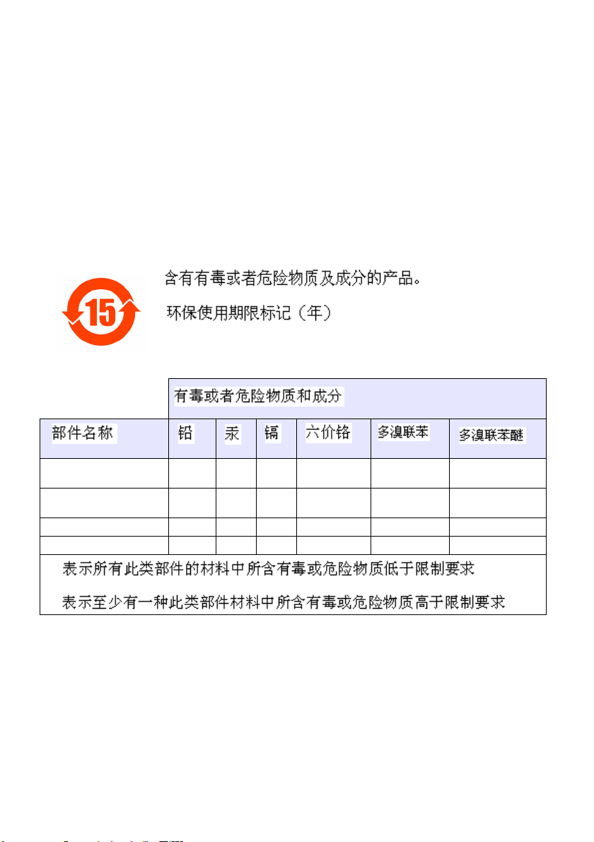
Restriction of hazardous substances (RoHS)
The European Union RoHS Directive and subsequent regulations introduced in member states and
other countries limits the use of six hazardous substances used in the manufacturing of electrical and
electronic equipment.
Currently, monitoring and control instruments do not fall within the scope of the RoHS Directive,
however Hach Lange has taken the decision to adopt the recommendations in the Directive as the
target for all future product design and component purchasing.
Note: The following only applies to exports of this product into the People’s Republic of China.
Conductivity plastic sensor
(8310, 8311, 8312)
Conductivity stainless
steel sensor (8314, 8394)
Digital sensor PCB O O
Glass electrode O O
O
OO
O:
X:
Page 4

Page 5

Inductive Probe 8398
Table of contents
1. INTRODUCTION................................................................................................ 3
1.1 General ....................................................................................................................3
1.2 Probes...................................................................................................................... 3
2. OPERATING PRINCIPLE.................................................................................. 4
2.1 Conductivity reminder ..............................................................................................4
2.2 Principle of inductive technology.............................................................................. 5
3. TECHNICAL SPECIFICATIONS ....................................................................... 6
3.1 Specifications...........................................................................................................6
3.2 Compliance ..............................................................................................................7
4. PROBE START-UP ........................................................................................... 7
4.1 Cable connection .....................................................................................................7
4.2 Use with a 8921 conductimeter................................................................................ 8
4.3 Use with a 9125 conductimeter................................................................................ 9
5. PROBE CALIBRATION..................................................................................... 9
6. INSTALLATION PRECAUTION ...................................................................... 11
7. ACCESSORIES ............................................................................................... 13
7.1 Probe 8398.2, 2" clamp model (08398=A=2000)...................................................13
7.2 Probe 8398.3, DIN 11851 / DN50 dairy connection model (08398=A=3000) ........14
7.3 Probe 8398.5, 1" threaded model gas ...................................................................16
8. MAINTENANCE............................................................................................... 18
9. PRECAUTIONARY LABELS........................................................................... 19
10. CHEMICAL RESISTANCE TABLE ................................................................. 20
2
Page 6
Inductive Probe 8398
1. INTRODUCTION
1.1 General
The 8398 range of probes makes use of inductive technology, which is particularly
recommended for corrosive and soiling uses, making use of conductivity or
concentration measurements. The main uses are as follows:
- Determination of solution concentrations: in-place cleaning, regeneration of
resin in water processing plants, surface treatment.
- Accurate interface control in conduits: in-place cleaning in the food and
pharmaceutical industries.
- Waste water testing: industrial and town sewerage plants.
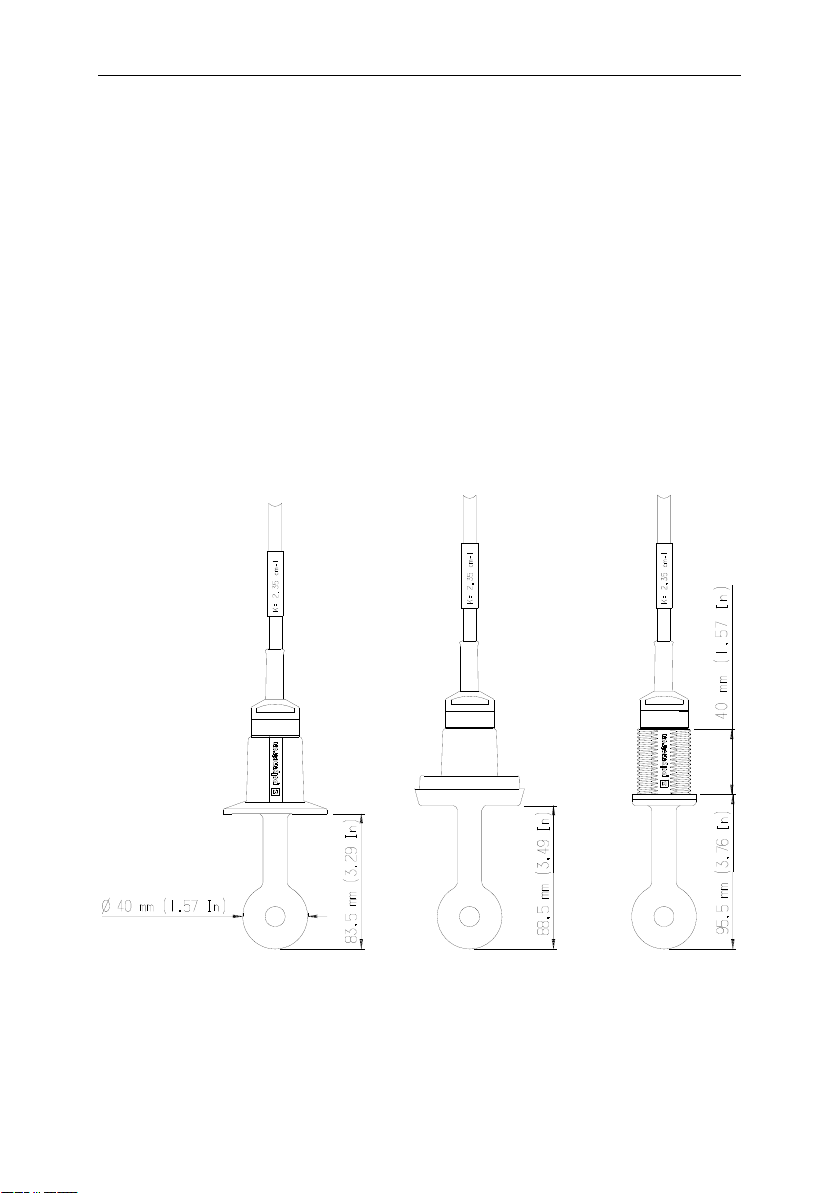
1.2 Probes
WARNING: Non-removable cable!
8398.2 8398.3 8398.5
2''clamp DN50 dairy connection 1'' Gas
3
Page 7
Inductive Probe 8398
D
2. OPERATING PRINCIPLE
2.1 Conductivity reminder
Electrolytic conductivity refers to the ability of a liquid to conduct an electrical current (conductivity is
the opposite of resistivity). In metals, the electrical current flows by electron displacement, in liquids it
flows by ion transport. The conductivity of a solution is dependent both upon the solution’s ionic
concentration and temperature.
To obtain a solution's actual conductivity (in S.cm-1), it is necessary to multiply the
measured conductance 1/R (in S) by a coefficient dependent solely upon the
geometry of the probe and termed "cell or K constant", expressed in cm
-1
.
K
C (S.cm
R
-1)
In order to allow the comparison between measurements made at different
temperatures, this measurement needs to be brought back to a
temperature
(generally 25 °C). This temperature dependency can be easily
reference
expressed in the form of relative variation in degrees Celsius. It is referred to as the
temperature coefficient (D).
C
= C T [1 + D (T - T
Tref
)]-1
ref
C
: Conductivity compensated to the reference temperature
Tref
C
: Conductivity measured at T
T
T
: Reference temperature (generally 25 °C)
ref
: Temperature coefficient of the solution (% / °C)
Examples:
Product Soda (NaOH)
5 %
D :
2.01 1.45
Nitric acid (HNO
10 %
)
3
REMARK:
1 S = 1000 mS (R = 1 :)
1 mS = 1000 μS (R = 1 k:)
4
Page 8
Inductive Probe 8398
x
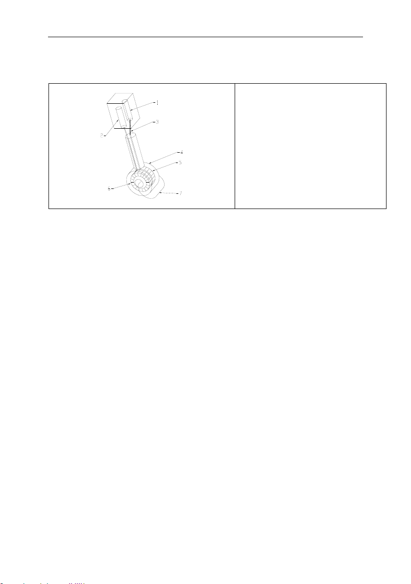
2.2 Principle of inductive technology
1 : Receiver
2 : Oscillator
3 : Cables
4 : Thermoplastic insulator
5 : Receiver
6 : Transmitter
7 : Induced current
The 8398 probes are made up of two coils that are completely insulated from the
process:
x The primary (or transmitter) coil, supplied with alternating voltage, produces an
alternating electromagnetic field that generates an electrical current in the solution.
x The secondary (or receiver) coil detects the size of the weak current induced by
the movement of ions in the solution.
The absence of contact between the electrical part and the solution (magnetic
coupling) provides a large number of advantages compared to the traditional
technique using metallic electrodes:
No polarisation and hence a broad measurement range.
x High chemical and mechanical resistance.
x Possibility of performing measurements in soiling products.
x Perfectly hygienic design.
5
Page 9
Inductive Probe 8398
3. TECHNICAL SPECIFICATIONS
3.1 Specifications
Measurement range 0 to 2000 mS/cm
Precision
r 2 % of the displayed value or r 0.004 mS/cm
Conductivity response < 1 s
Temperature response T 50 % = 20 s
T 90 % = 2 mn
Cell constant K = 2.35 cm-1
Roughness Ra < 0.5 μm (roughness certificate on request,
Ref.: 08398=T=1111)
Chemical resistance Our mono-block probe is made from PEEC
(poly ether ether Ketone), whose chemical
resistance is summarised in the table §9.
WARNING: PEEC is not resistant to high
concentrations of oxidative acids (nitric and
sulphuric acid > 70 %, etc.) In the case of
probe 8398.5, one must consider the other
materials in contact with the process (EPDM or
VITON gaskets, PP or 316 stainless steel
extension, etc.).
Mechanical resistance PEEC possesses a flexion temperature
(pressure: 18 bars) of approximately 300 °C.
In the case of probe 8398.5, take account of
extensions, if any.
Heat resistance PEEC is a polymer that is particularly well-
suited to sterilisation, it can therefore withstand
temperatures of 140 °C.
6
Page 10

Inductive Probe 8398
3.2 Compliance
i Probes are factory tested and are delivered with a certificate of compliance with
specifications.
Models 8398.2 and 8398.3 are particularly well-suited to applications where
sanitary requirements are extremely stringent (compliance with the European food
directive 90/128/CE modified by directive 93/9/CE). Indeed, these probes do not
possess any retention zones that could allow the development of bacteria
(interstices, slits, joints, etc.) and have a roughness inferior to 0.5 μm (optional
certificate, ref. 08398=T=1111).
i The measurement chain, made up of an 8398 probe and of our conductivity
transmitters, complies with European directives 89/336/CEE and 73/23/CEE
modified by directive 93/68/CEE.
4. PROBE START-UP
4.1 Cable connection
WARNING: Fit the DN50 clamping nut or the immersion rod onto the probe before
wiring!
Make the following connections
COND 9125 COND 8921
(channels 1 and 2)
1 : GREEN or yellow (Pt100) TEMP + 14 and 19
2 : YELLOW or green (Pt100) TEMP - 15 and 20
GND 30 and 32 3 : BLACK (secondary coil shielding)
4 : WHITE (secondary coil)
IN 31 and 33
GND 16 and 21 5 : BLACK (primary coil shielding)
6 : BROWN (primary coil)
7 : WHITE (external shielding) EXTERNAL
OUT 17 and 22
EXTERNAL SHIELDING
SHIELDING
REMARK: The probe is fitted as standard with 5 metres of cable. We recommend
not cutting this cable in order to avoid any connection errors. If the
length is insufficient, please order the following accessories:
x Junction box, ref.: 08335=A=6000
x Cable (per metre, maximum 50 m), ref.: 150727,10000
7
Page 11

Inductive Probe 8398
4.2 Use with a 8921 conductimeter
EPROM
The use of a type 8398 inductive probe connected to a type 8921 2-channel
conductimeter requires that this latter be fitted with a software version greater than or
equal to the following versions:
Software Minimum
Memory reference
version no.
Standard 3.76 08921=A=6200
Concentration 1.04 08921=A=6400
Special 4.07 08921=A=6305
To install your new software version, proceed as follows:
x Remove the transmitter's front panel (4 screws).
x On the rear of the front panel, there are two circuit boards. Remove the first of
these two circuit boards (4 screws).
x At the rear of this printed circuit board, carefully change the integrated circuit
(EPROM) represented on the figure opposite.
x Check that the memory has been inserted in the correct position, otherwise it
would be irreversibly damaged.
x Re-fit the front panel and initialise the instrument's default parameters using
command 900.
x Reprogram the instrument to your configuration and configure command
(102)
with Argument 2, which corresponds to the 8398 probe's cell constant,
C101
equal to 2.35.
8
Page 12

Inductive Probe 8398
4.3 Use with a 9125 conductimeter
Set the two switches (I/K) inside the instrument to position I.
Check that the measurement type is set to inductive.
5. PROBE CALIBRATION
REMARK: For more detailed information, see the user instructions of out 9125 and
8921 transmitters. We recommend proceeding in the following order:
Set the cell constant value on your transmitter to 2.35 cm
-1
.
Calibrate your temperature sensor:
Submerge the probe in a solution for approximately 10 min., raise the temperature of
this solution using a thermometer (accurate to r 0.1°C if possible). Set the transmitter
to process calibration mode, then adjust the temperature value.
Calibrate conductivity (two solutions)
Electrical calibration:
Perform the "electrical" calibration of the probe with a decade box, using a wire no
longer than 50 cm and with a minimum cross-section of 0.38 mm².
The resistance values to use are: f for zero adjustment (decade box disconnected):
then 200 Ohms (default instrument value) for slope adjustment:
9
Page 13

Inductive Probe 8398
REMARK
: After returning to measurement mode, the value displayed by the
transmitter takes account of the cell constant and also of
temperature compensation.
Example: 200 Ohms on decade box, T = 20 °C, transmitter set for 25 °C
compensation with a coefficient of 2 %, unit mS/cm:
DISPLAY: [2.35/200]. [1 + 0.02 u (20 - 25)]
-1
= 13.06 mS/cm (c.f. Ch. 2-1)
Process calibration (9125 only):
During the first calibration of the chain, process calibration must be performed at two
distinct points (probe in air, then in the control solution).
After this, calibration can be performed on a single point (control solution only).
WARNING:
If you are using a 9125 with software version < 1.12, the cell
constant value must be set prior to calibration.
Any alteration of the cell constant value after calibration would cancel the
calibration for this probe (slope reset to 100 %).
10
Page 14

6. INSTALLATION PRECAUTION
Inductive Probe 8398
Minimum distance between probe and conduit
When the electrical field lines are partially obstructed by a wall, the measured
conductivity is altered (increased if the wall is a conductor, decreased if it is an
insulator). With our "high performance" shielding system, 100 % of the field lines of
our probe are channelled to within less than 10 mm, thus allowing
be made without disturbance in DN65 conduits
.
measurements to
It is also possible to perform measurements in DN50 conduits, using our DN65 /
DN50 converging / diverging T-pieces (reference 08398=A=6000 for 8398.3 probes
and 08398=A=7000 for 8398.2 probes). These T-pieces therefore allow users to
connect to DN50 conduits, while performing their measurements in a DN65 diameter.
WARNING: In order to work optimally, the probe must be completely submerged in
the liquid. We therefore recommend the use of a U-bend tube.
11
Page 15

Inductive Probe 8398
o
Installation direction
The opening of the probe must face the conduit's flow direction, thus avoiding the
influence of flow rate and to perform the self-cleaning of this opening. For optimal
operation, the "POLYMETRON" marking should be positioned in the conduit's flow
direction, as shown in the following figure:
: flow direction in the conduit
12
Page 16

Inductive Probe 8398
7. ACCESSORIES
There are three probe versions, that are distinguished by the type of connector used.
7.1 Probe 8398.2, 2" clamp model (08398=A=2000)
APPLICATION: FREE FLOW
Number: Reference: Designation Installation
1 581=000=510
2" stainless steel clamp collar
-
2 429=500=510 EPDM joint for 2" clamp -
6 581=100=510 2" stainless steel ferrule to weld Min. DN65
1+2+6 08398=A=0510 Kit with 2" stainless collar
Min. DN65
+ 2" EPDM joint + 2" stainless ferrule
1+2+3 08398=A=7500 Kit with 2" stainless collar
DN65
+ 2" EPDM joint + DN65 stainless
T-piece
1+2+4 08398=A=7000 Kit with 2" stainless collar + 2" EPDM
DN50
joint + DN65/50 stainless T-piece
1+2+5 08398=A=8200 Kit with 2" stainless collar
Derivation
+ 2" EPDM joint + Stainless flow
chamber (inlet / outlet 1/4" NPT)
13
Page 17

7.2 Probe 8398.3, DIN 11851 / DN50 dairy connection model
(08398=A=3000)
APPLICATION: FREE FLOW
Inductive Probe 8398
14
Page 18

Inductive Probe 8398
Number: Reference:
1 402=400=500
Designation
Stainless steel DN50 DIN screw
2 429=600=500 EPDM DIN DN50 joint
7 429=600=501 VITON DIN DN50 joint
6 581=200=500 DIN DN50 stainless steel ferrule to weld
(H = 35 mm)
1+2+6 08398=A=0500 Kit with DN50 stainless screw + EPDM
DN50 joint + DN50 stainless ferrule to
weld (H = 35 mm)
1+7+8 08398=A=5310 Kit with DN50 stainless screw + VITON
DN50 joint + PVC ferrule to glue
(H = 23 mm)
1+2+9 08398=A=5320 Kit with DN50 stainless screw + EPDM
DN50 joint + PP ferrule to weld
(H = 23 mm)
1+7+10 08398=A=5330 Kit with DN50 stainless screw + VITON
DN50 joint + PVDF ferrule to weld
(H = 23 mm)
1+2+4 08398=A=6000 Kit with DN50 stainless screw + EPDM
DN50 joint + DN65/50 T-piece
1+2+3 08398=A=6500 Kit with DN50 stainless screw + EPDM
DN50 joint + DN65 stainless T-piece
1+2+5 08398=A=8300 Kit with DN50 stainless screw + EPDM
DN50 joint + Stainless flow chamber
(inlet / outlet 1/4" NPT)
1+7+11 08398=A=8310 Kit with DN50 stainless screw + VITON
DN50 joint + PVC flow chamber
(inlet / outlet 1/2" gas)
1+2+12 08398=A=8320 Kit with DN50 stainless screw + EPDM
DN50 joint + PP flow chamber
(inlet / outlet 1/2" gas)
1+7+13 08398=A=8330 Kit with DN50 stainless screw + VITON
DN50 joint + PVDF flow chamber
(inlet / outlet 1/2" gas)
Installation
Min. DN65
Min. DN65
Min. DN65
Min. DN65
DN50
DN65
Derivation
Derivation
Derivation
Derivation
15
Page 19

7.3 Probe 8398.5, 1" threaded model gas
Inductive Probe 8398
Remark: Flanges are not supplied individually.
This model is a universal model, specially adapted to immersion measurements. it is
supplied as standard with an EPDM sheet gasket, an optional Viton joint
(ref. 08398=C=3438) is also available, along with the stainless steel 1"G screw
(402=700=010).
We propose as standard several PP and 316 L stainless steel accessories for
immersion at various depths (0.5/1/1.5/2 m):
16
Page 20

Inductive Probe 8398
Reference Material Immersion (m) Flange Immersion
setting
08335=A=5005 PP 0.5 DN65 PVC Adjustable
08335=A=5010 PP 1 DN65 PVC Adjustable 08398=A=1014
08335=A=5015 PP 1.5 DN65 PVC Adjustable 08398=A=1014
08335=A=5020 PP 2 DN65 PVC Adjustable 08398=A=1014
08398=A=6005 PP 0.5 DN50 PP Fixed -
08398=A=6010 PP 1 DN50 PP Fixed -
08398=A=6015 PP 1.5 DN50 PP Fixed -
08398=A=6020 PP 2 DN50 PP Fixed -
08398=A=6605 PP 0.5 DN50 PVC Adjustable -
08398=A=6610 PP 1 DN50 PVC Adjustable -
08398=A=6615 PP 1.5 DN50 PVC Adjustable -
08398=A=6620 PP 2 DN50 PVC Adjustable -
08350=A=1105 PP 0.5 - Clip
08350=A=1110 PP 1 - Clip 08398=C=0300
08350=A=1115 PP 1.5 - Clip 08398=C=0300
08350=A=1120 PP 2 - Clip 08398=C=0300
08878=A=1500 STAINLESS 1.5 (*) Adjustable 08398=C=0500
Adapter required
08398=A=1014
(H = 150 mm)
08398=C=0300
(H = 130 mm)
(*): No flange, to be used with 08878=C=1600 support
17
Page 21

Inductive Probe 8398
8. MAINTENANCE
WARNING: Read the "installation precaution" and "cable connection" chapters
carefully.
o If there is a doubt concerning the operation of a probe, disconnect it from the
transmitter, leaving it in place on your process and ensure that you obtain the
following resistance values (see 4.1 Cable connection):
R (1-2) | 110 : (at 25 °C) (Temperature sensor Pt100)
R (3-4) | [1…2] : (Secondary coil)
R (5-6) | [1…2] : (Primary coil)
R (3-5) f : (Coil electrical insulation)
o If the checks performed do not generate any erroneous resistance values, the
probe can be considered to be working properly.
o If the measurement is still not satisfactory, remove the probe from the process and
calibrate it (see "probe calibration" chapter), set the transmitter to "no temperature
compensation", then check the following points:
Displayed conductivity (K = 2.35) Simulated resistance
470 μS/cm 5 k:
4.7 mS/cm 500 :
47 mS/cm 50 :
470 mS/cm 5 :
18
Page 22

Inductive Probe 8398
9. PRECAUTIONARY LABELS
Read all labels and tags attached to the instrument. Personal injury or damage to this
instrument could occur if not observed.
This symbol, if noted on the instrument, references the instruction
!
manual for operation and / or safety information.
Electrical equipment marked with this symbol may not be disposed of
in European public disposal systems after 12 August of 2005. In
conformity with European local and national regulations (EU
Directive 2002/96/EC), European electrical equipment users must
now return old or end-of life equipment to the Producer for disposal
at no charge to the user.
Note: For return for recycling, please contact the equipment producer or supplier for
instructions on how to return end-of-life equipment for proper disposal.
Important document. Retain with product records.
19
Page 23

Inductive Probe 8398
10. CHEMICAL RESISTANCE TABLE
0: yes, -: no,
x: momentarily
% 20 60 100 20 60 100 20 60 100
Sulphuric acid 10
Hydrochloric acid 10
Nitric acid < 25
Phosphoric acid < 25
Hydrofluoric acid 40
Acetic acid 10
Formic acid 80 x x x 0 0 0 0 0 -
Citric acid 50 0 0 0 0 0 0 0 0 0
Calcium hydroxide Sat 0 0 0 0 0 0 0 0 -
Potassium hydroxide 50 0 0 0 0 0 x 0 0 -
Sodium hydroxide 10
Ammonia 10
Ammonium chloride Sat 0 0 0 0 0 0 0 0 0
Zinc chloride 50 0 0 0 0 0 0 0 0 -
Iron chloride 50 0 0 0 0 0 0 0 0 0
Sodium sulphite Sat 0 0 0 0 0 0 0 0 -
Sodium carbonate Sat 0 0 0 0 0 0 0 0 -
Potassium chloride Sat 0 0 0 0 0 0 0 0 0
Sodium sulphate Sat 0 0 0 0 0 0 0 0 0
Calcium chloride Sat 0 0 0 0 0 0 0 0 0
Sodium chloride Sat 0 0 0 0 0 0 0 0 0
Sodium nitrate 50 0 0 0 0 0 0 0 0 -
Aluminium chloride Sat 0 0 0 0 0 0 0 0 0
Hydrogen peroxide 30 0 0 0 0 0 0 0 0 -
Sodium hypochlorite 50 0 0 0 0 0 0 x x -
Potassium dichromate Sat 0 0 0 0 0 0 0 0 0
Chlorinated salt water 0 0 0 0 x - - - -
Ethanol 80 0 0 0 0 0 x 0 0 0
Cyclohexane 0 0 0 0 0 x - - -
Toluene 0 0 0 0 0 0 x - -
Trichloroethane 0 0 0 x x x - - -
Water 0 0 0 0 0 0 0 0 0
(°C)
50
95
Sat
50
95
50
95
75
glacial
40
30
PEEK
0
0
0
0
-
-
0 0 0 0 x
0
0
x
x
-
-
0
0
0
0
0
0
-
-
-
-
0 0 0 0 0 x 0 0 0 x 0 - 0 0 0 x 0
0 0 0 0 0 0 0 0 x
0 0 0 0 0 0 0 0 0 0 0 0 0 0 0 0 -
PVDF
0
0
0
x
0
-
0
0 0 0 0 0 0 0 0 0 0 x
x
0
0
x
0
-
0
0
0
0
0
0
0
-
0 0 0 0 0 0 0 0 0 0 -
-
0
0
0
x
-
0
x
0
x
x
-
0
0
0
0
0
0
0 - x 0 0 0 0 0 -
PP
0
0
0
0
0
0
0
0
x
-
0
x
-
-
-
0
0
0
0
x
-
x
-
-
-
0
-
-
-
-
-
20
Page 24

Inductive Probe 8398
0: yes, -: no,
x: momentarily
20 60 100 20 60 100 20 60 100
Sulphuric acid 10
Hydrochloric acid 10
Nitric acid < 25
Phosphoric acid < 25
Hydrofluoric acid 40
Acetic acid 10
Formic acid 80 0 0 x - - - 0 x x
Citric acid 50 0 0 0 0 0 0 0 0 0
Calcium hydroxide Sat 0 0 0 0 0 0 0 0 0
Potassium hydroxide 50 0 0 x x x - 0 0 0
Sodium hydroxide 10
Ammonia 10
Ammonium chloride Sat 0 0 0 0 0 0 x x x
Zinc chloride 50 0 0 0 0 0 0 x x x
Iron chloride 50 0 0 0 0 0 0 - - -
Sodium sulphite Sat 0 0 0 0 0 - 0 0 0
Sodium carbonate Sat 0 0 - 0 0 0 0 0 0
Potassium chloride Sat 0 x - 0 0 0 0 x x
Sodium sulphate Sat 0 0 0 0 0 0 0 0 0
Calcium chloride Sat 0 0 0 0 0 0 0 0 x
Sodium chloride Sat 0 0 0 0 0 0 x x x
Sodium nitrate 50 0 0 0 0 0 0 x x x
Aluminium chloride Sat 0 0 0 0 0 0 - - -
Hydrogen peroxide 30 0 0 - 0 0 0 0 0 0
Sodium hypochlorite 50 x x - 0 0 x x x x
Potassium dichromate Sat 0 x x 0 0 0 0 0 x
Chlorinated salt water - - - 0 x - - - -
Ethanol 80 0 0 0 0 x x 0 0 0
Cyclohexane - - - 0 0 0 0 0 0
Toluene - - - - - - 0 0 0
Trichloroethane - - - x x x 0 0 -
Water 0 0 0 0 0 0 0 0 0
50
95
sat
50
95
50
95
75
glacial
40
30
EPDM
0
0
0
x
x
-
0 - 0 - 0 - 0 0 0 0 0 0 - - - - -
0
x
-
-
-
-
0
0
0
0
x
x
-
-
-
-
0 0 0 x 0 - x
0 0 0 0 x
0 0 0 0 0
VITON
0
0
0
-
0
-
0
-
0
-
0
-
0
0
0
x
0
-
x
-
0 0 0 0 0 0 - - - - -
-
-
0 0 x
x
-
0
-
0
0
x
x
-
0
0
0
0
0
x
0
0
0
0
x
-
x
- - 0 0 0 0 x
-
- - 0 0 0 0 0
x
-
- - 0 0 0 0 0
-
316 L
0
x
x
0
0
0
-
-
-
x
x
x
x
x
x
-
0
0
x
x
x
x
-
-
-
-
-
-
-
x
0
-
21
Page 25

Page 26

Page 27

Page 28

 Loading...