

Page 1
DOC023.52.00026
PHOSPHAX sc, PHOSPHAX indoor sc
USER MANUAL
07/2012, Edition 5A
PHOSPHAX sc, PHOSPHAX indoor sc
© HACH-LANGE GmbH, 2006–2010; 2012. All rights reserved. Printed in Germany. sd/sk
Page 2

Page 3

Table of Contents
Section 1 Specifications .........................................................................................................5
Section 2 General Information ...............................................................................................9
2.1 Safety information ....................................................................................................................... 9
2.1.1 Use of hazard information .................................................................................................. 9
2.1.2 Precautionary labels ........................................................................................................ 10
2.1.3 Change instrument labels ................................................................................................ 11
2.2 Product overview ...................................................................................................................... 11
Section 3 Installation ............................................................................................................13
3.1 Basic installation overview ........................................................................................................ 13
3.2 Unpack the instrument .............................................................................................................. 13
3.3 Mechanical installation .............................................................................................................. 14
3.3.1 Mount the instrument ....................................................................................................... 14
3.3.1.1 Wall mount ..............................................................................................................14
3.4 Initial instrument setup .............................................................................................................. 17
3.4.1 Open the enclosure .......................................................................................................... 17
3.4.2 Remove the shipping transport locks ............................................................................... 19
3.4.3 Installation of the collecting tray .......................................................................................20
3.4.4 Connect the humidity sensor ........................................................................................... 22
3.4.5 Connect the sample supplies and drain ........................................................................... 23
3.5 Electrical installation ................................................................................................................. 24
3.5.1 Electrostatic Discharge (ESD) Considerations ................................................................ 25
3.5.2 Enclosure breakouts ........................................................................................................ 25
3.5.3 Insert tubing and/or cables ...............................................................................................26
3.5.4 Connect the Filter Probe sc to the analyzer (optional) ..................................................... 26
3.5.5 Connect the optional heated drain ................................................................................... 27
3.6 Installation of reagents .............................................................................................................. 29
3.7 Supply power to the analyzer .................................................................................................... 31
3.8 Connect the data network ......................................................................................................... 32
Section 4 System Startup .....................................................................................................33
4.1 Initializing the instrument .......................................................................................................... 33
Section 5 Operation ..............................................................................................................35
5.1 Sensor diagnostics menu .......................................................................................................... 35
5.2 Sensor setup menu ................................................................................................................... 35
5.2.1 System setup menu .........................................................................................................39
5.3 Cleaning process ...................................................................................................................... 39
5.4 Measurement process .............................................................................................................. 40
Section 6 Maintenance ..........................................................................................................41
6.1 General maintenance ................................................................................................................ 41
6.1.1 Clean the analyzer ........................................................................................................... 41
6.1.2 Reagent replacement .......................................................................................................41
6.1.3 Replace the fan filter ........................................................................................................ 41
6.1.4 Fuse replacement ............................................................................................................ 42
6.2 Routine maintenance schedule ................................................................................................. 43
6.3 Validation (Analytical quality assurance) ..................................................................................43
6.4 Shut the analyzer down ............................................................................................................ 45
6.4.1 Shut the analyzer down for an extended period .............................................................. 45
6.5 Scheduled maintenance ........................................................................................................... 46
6.6 Modify from single channel to dual channel .............................................................................. 46
3
Page 4

Table of Contents
Section 7 Troubleshooting ...................................................................................................47
7.1 Troubleshooting the controller ...................................................................................................47
7.2 Troubleshooting the analyzer ....................................................................................................47
7.2.1 LED status ........................................................................................................................47
7.2.2 Error messages ................................................................................................................47
7.2.3 Warnings .........................................................................................................................49
Section 8 Replacement Parts and Accessories ................................................................ 51
8.1 Standards and reagents ............................................................................................................51
8.2 Analyzer accessories ................................................................................................................51
8.3 Mounting hardware ....................................................................................................................51
8.4 Replacement parts ....................................................................................................................51
Section 9 Contact Information ............................................................................................59
Section 10 Limited Warranty ................................................................................................61
Section 11 Certification .........................................................................................................63
Appendix A Plumbing and connection options ................................................................. 65
A.1 Safety information .....................................................................................................................65
A.1.1 Electrostatic Discharge (ESD) Considerations .................................................................65
A.2 Connect a 2-parameter option ..................................................................................................66
A.2.1 Remove the T-fitting .........................................................................................................67
A.3 Drain line considerations ...........................................................................................................67
A.4 Tubing considerations ...............................................................................................................67
A.5 Option 1 plumbing and connections ..........................................................................................68
A.6 Option 2 plumbing and connections ..........................................................................................70
A.7 Option 3 plumbing and connections ..........................................................................................72
A.8 Option 4 plumbing and connections ..........................................................................................74
A.9 Option 5 plumbing and connections ..........................................................................................77
A.10 Option 6 plumbing and connections ........................................................................................79
A.11 Option 7 plumbing and connections ........................................................................................81
A.12 Option 8a plumbing and connections ......................................................................................83
A.13 Option 8b plumbing and connections ......................................................................................85
A.14 Option 9a plumbing and connections ......................................................................................87
A.15 Option 9b plumbing and connections ......................................................................................89
A.16 Option 10a plumbing and connections ....................................................................................91
A.17 Option 10b plumbing and connections ....................................................................................93
A.18 Option 11a plumbing and connections ....................................................................................95
A.19 Option 11b plumbing and connections ....................................................................................97
Appendix B Fieldbus .............................................................................................................99
B.1 Fieldbus control .........................................................................................................................99
B.2 Remote controlled measurement series ...................................................................................99
B.3 External trigger contact, control by external signal .................................................................100
11.1 Modbus register information ..................................................................................................101
4
Page 5

Section 1 Specifications
Specifications are subject to change without notice.
Enclosure rating
PHOSPHAX sc: IP55
PHOSPHAX indoor sc: IP54
Enclosure material ASA/PC UV-resistant
Measuring method 2-beam photometer (yellow method)
Measuring range
Detection limit
Measuring accuracy
(with standard solution)
Repeatability
(with standard solution)
0.05 to 15 mg/L PO
1 to 50 mg/L PO
0.05 mg/L, with standard solution: (0.05 to 15 mg/L PO
1.00 mg/L, with standard solution (1 to 50 mg/L PO
2 % of the measured value + 0.05 mg/L (0.05 to 15 mg/L PO
2 % of the measured value + 1.0 mg/L (1 to 50 mg/L PO
2 % of the measured value + 0.05 mg/L (0.05 to 15 mg/L PO
2 % of the measured value + 1.0 mg/L (1 to 50 mg/L PO
–P
4
–P
4
–P Measuring Range)
4
–P Measuring Range)
4
–P Measuring Range)
4
–P Measuring Range)
4
–P Measuring Range)
4
–P Measuring Range)
4
Response time (90 %) < 5 minutes
Adjustable measuring interval 5 to 120 minutes
Power supply
Power supply with power cable, using the sc1000 controller only
(analyzer, Filter Probe sc, and drain tubing: 115 V versions or 230 V versions)
Data transmission Data transmission with data cable on the sc1000 controller
Electrical power consumption 500 VA
Electrical fuse protection
Outputs
Via sc1000 controller
Maximum of 2 analysis instruments for each sc1000.
Relay, current outputs, network interface via sc1000 controller. Refer to the sc1000
manual for detailed specifications for analog, relay, and digital outputs.
PHOSPHAX sc: –20 to 45 °C (–4 to 113 °F); 95 % relative humidity,
Operating temperature
non-condensing
PHOSPHAX indoor sc: 5 to 40 °C (41 to 104 °F); 95 % relative humidity,
non-condensing
Storage temperature –20 to 60 °C (–4 to 140 °F); 95 % relative humidity, non-condensing
Sample temperature +4to +45°C (39to 113°F)
Sample pressure With continuous sample preparation –30 mbar to +50 mbar at overflow vessel
Sample flow Range: 1.0–20.0 L/h
Sample quality Ultra filtrated or
comparable
Sample level Level of liquid in basin with filtration probe must be below analyzer
Permissible pH value of the sample 5 to 9
Permissible chlorid range 1000 mg/L Cl
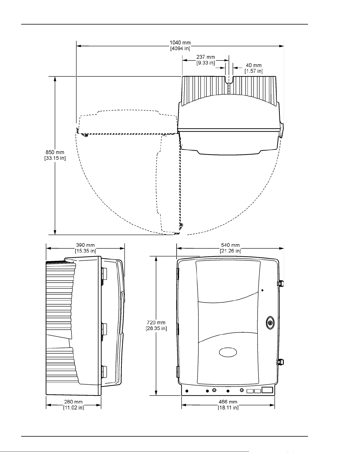
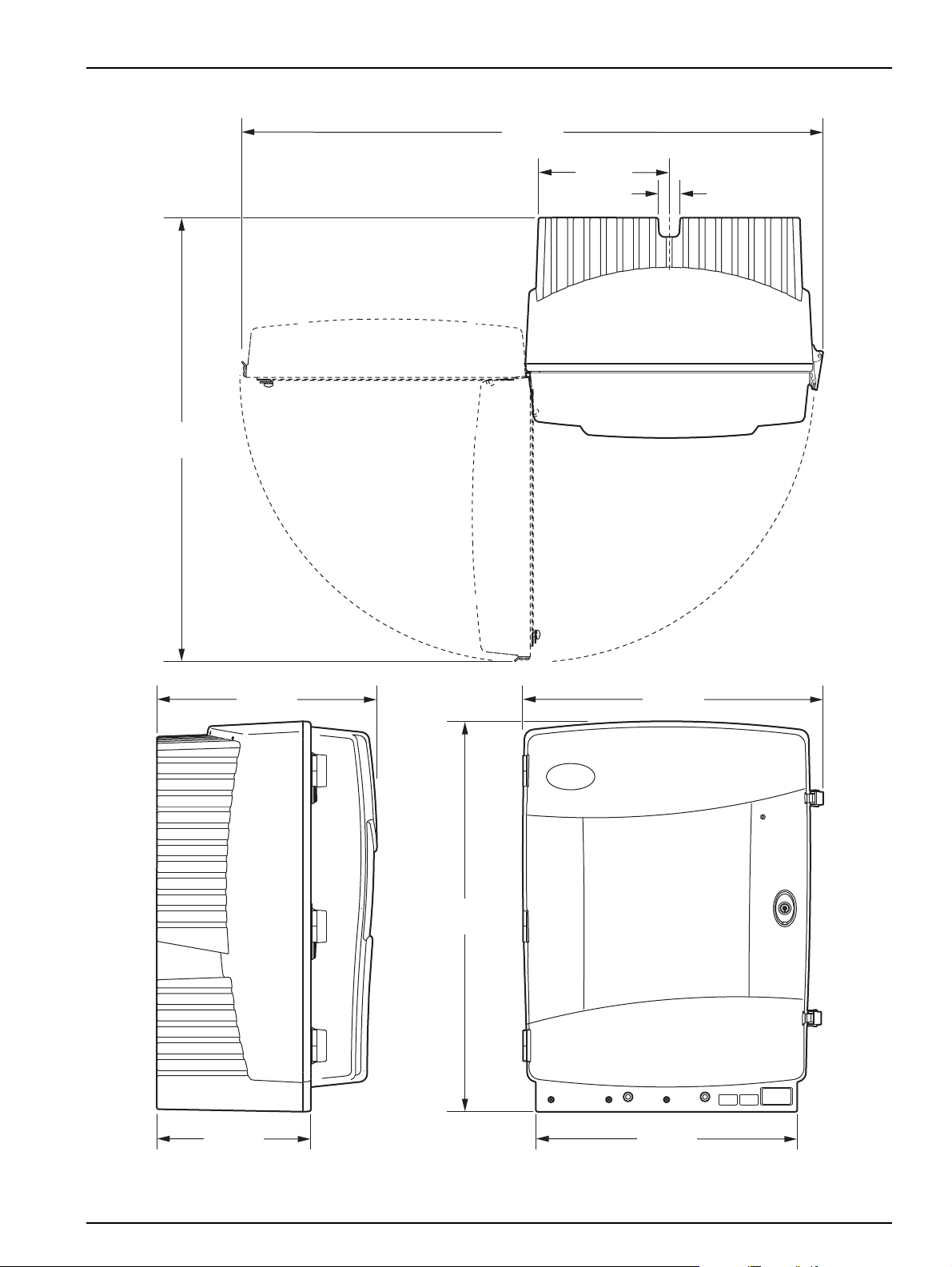
Dimensions (Figure 1 on page 6,
Figure 2 on page 7)
PHOSPHAX sc: (W × H × D) 540 × 720 × 390 mm (21.25 × 28.35 × 15.35 in.)
PHOSPHAX indoor sc: (W × H × D) 540 × 720 × 370 mm (21,25 × 28,35 × 14.5 in.)
–
Data and power cable lengths 2 m (80 in.) (from edge of enclosure)
PHOSPHAX sc: Approximately 31 kg, without Filter Probe sc and without
Weight
chemicals
PHOSPHAX indoor sc: Approximately 29 kg, without Filter Probe sc and without
chemicals
5
Page 6
Specifications
Figure 1 Instrument dimensions PHOSPHAX sc
6
Page 7
40 mm
[1.57 in]
237 mm
[9.33 in]
850 mm
[33.15 in]
1040 mm
[4094 in]
720 mm
[28.35 in]
540 mm
[21.26 in]
466 mm
[18.11 in]
390 mm
[15.35 in]
280 mm
[11.02 in]
Specifications
Figure 2 Instrument dimensions PHOSPHAX indoor sc
7
Page 8

Specifications
8
Page 9

Section 2 General Information
2.1 Safety information
Please read this entire manual before unpacking, setting up or
operating this equipment. Pay attention to all danger and caution
statements. Failure to do so could result in serious injury to the
operator or damage to the equipment.
Make sure that the protection provided by this equipment is not
impaired, do not use or install this equipment in any manner other
than that specified in this manual.
2.1.1 Use of hazard information
DANGER
Indicates a potentially or imminently hazardous situation
which, if not avoided, will result in death or serious injury.
WARNING
Indicates a potentially or imminently hazardous situation
which, if not avoided, could result in death or serious injury.
CAUTION
Indicates a potentially hazardous situation that may result in
minor or moderate injury.
Important Note: Indicates a situation which, if not avoided, may
cause damage to the instrument. Information that requires special
emphasis.
Note: Information that supplements points in the main text.
9
Page 10
General Information
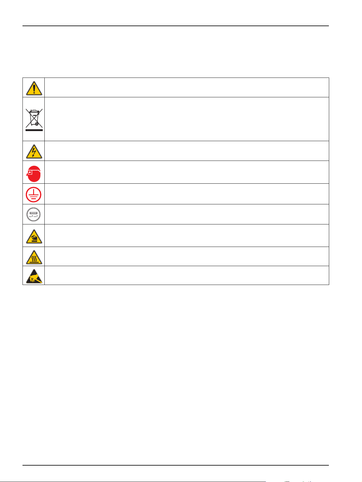
2.1.2 Precautionary labels
This symbol, if noted on the instrument, references the instruction manual for operation and/or safety information.
Electrical equipment marked with this symbol may not be disposed of in European public disposal systems after
12 August of 2005. In conformity with European local and national regulations (EU Directive 2002/96/EC), European
electrical equipment users must now return old or end-of life equipment to the Producer for disposal at no charge to
the user.
Note: For return for recycling, please contact the equipment producer or supplier for instructions on how to return
end-of-life equipment, producer-supplied electrical accessories, and all auxiliary items for proper disposal.
This symbol, when noted on a product enclosure or barrier, indicates that a risk of electrical shock and/or
electrocution exists.
This symbol, if noted on the product, indicates the need for protective eye wear.
This symbol, when noted on the product, identifies the location of the connection for Protective Earth (ground).
Read all labels and tags attached to the instrument. Personal injury
or damage to the instrument could occur if not observed. A symbol,
if noted on the instrument, will be included with a danger or caution
statement in the manual.
This symbol, when noted on the product, identifies the location of a fuse or current limiting device.
This symbol, when noted on the product, identifies a risk of chemical harm and indicates that only individuals
qualified and trained to work with chemicals should handle chemicals or perform maintenance on chemical delivery
systems associated with the equipment.
This symbol, when noted on the product, indicated that the marked item can be hot and should not be touched
without care.
This symbol, when noted on the product, indicated the presence of devices sensitive to Electro-static Discharge
(ESD) and indicated that care must be taken to prevent damage with the equipment.
10
Page 11
2.1.3 Change instrument labels
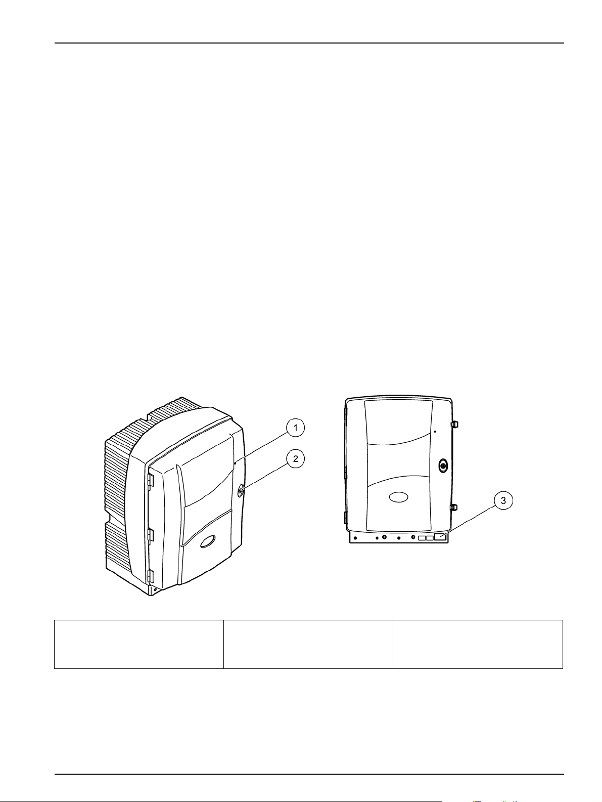
2.2 Product overview
General Information
Several safety labels (3 in the analytical section) are applied to the
instrument. If necessary, apply the correct language label over the
existing safety labels.
The PHOSPHAX sc (Figure 3, Figure 4) measures
ortho-phosphate ions (PO
3–
) in waste water and surface water.
4
Diphosphates and polyphosphates are not measured. The
PHOSPHAX sc must be used in combination with the sc1000
controller. The sc1000 controller is used to configure, power, and
output the measured values. The measured value is displayed in
unit of mg/L PO
To convert the measured value of PO
following conversion formula: PO
–P on the controller.
4
–P to PO
4
–P x 3.07 = PO
4
3–
, use the
4
3–
4
The PHOSPHAX sc can operate using single or dual channel
modes. Operation with the Filter Probe sc uses single channel only
The sc analyzer can be converted from a single channel operation
to dual channel operation. Contact the manufacturer for more
information.
Dual-channel operation is only possible with continuous sample
preparation, e. g. FILTRAX or Ultrafiltration. Sample preparation
and filtration must be provided before installing the instrument.
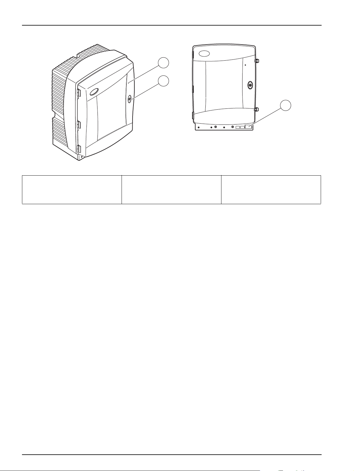
1 LED for operating state. Refer to
Table 7, page 47 for more
information.
Figure 3 PHOSPHAX sc enclosure
2 Door lock 3 Rating plate with model number,
serial number, voltage and
frequency information, and power
consumption information
11
Page 12
General Information
1
2
3
1 LED for operating state. Refer to
Table 7, page 47 for more
information.
Figure 4 PHOSPHAX indoor sc enclosure
2 Door lock 3 Rating plate with model number,
serial number, voltage and
frequency information, and power
consumption information
12
Page 13

Section 3 Installation
3.1 Basic installation overview
DANGER
Only qualified personnel should conduct the tasks described
in this section of the manual.
CAUTION
Good safety habits and technique should be observed at all
times. Review all SDS/MSDS information and use
recommended safety measures to prevent exposure to
potential chemical hazards.
1. Unpack the instrument (section 3.2).
2. Mount the instrument (section 3.3, page 14).
3. Remove any transport locks (section 3.4.2, page 19).
4. Install the collecting tray and the humidity sensor (section 3.4.3,
page 20 and section 3.4.4, page 22).
5. Determine the appropriate installation option (section 3.4.5,
page 23).
6. Mount the Filter Probe sc or Filtrax, if necessary. Refer to the
appropriate manual for more information.
3.2 Unpack the instrument
7. Connect the Filter Probe sc or Filtrax to the PHOSPHAX sc, if
necessary. Refer to section 3.5.4, page 26 for the Filter Probe
sc. Refer to the Filtrax manual for more information.
8. Connect the Drain Heating Connection, if necessary
(section 3.5.5, page 27).
9. Make all plumbing connections (Appendix A Plumbing and
connection options on page 65).
10. Install the reagents (section 3.6, page 29).
11. Connect the PHOSPHAX sc to the sc1000 controller to supply
power to the system (section 3.7, page 31).
12. Connect the data network (section 3.8, page 32).
CAUTION
Pay attention to the weight (approximately 31 kg) of the
instrument. Do not try to carry the instrument without
assistance. Use only suitable lifting tackle for transport.
Open the shipping container while it is on its end and then slide the
analyzer out of the cardboard.
The items supplied will vary depending on the order.
Standard items supplied for a minimal configuration:
• PHOSPHAX sc and User Manual
• Collecting tray
• Initial set of reagent and cleaning solution
• Fastening bracket and angle bracket
• Accessories for tubing and flow-through variant
• Plug set
13
Page 14

Installation
3.3 Mechanical installation
3.3.1 Mount the instrument
Select a suitable place to install the instrument. Plan the
mechanical installation before positioning posts or drilling holes.
Refer to Figure 1 for instrument dimensions.
Make sure that the fastening has sufficient load bearing capacity
(approximately 160 kg). The wall plugs must be selected and
approved to suit the properties of the wall.
Plan cable and tubing routes to avoid sharp bends and tripping
hazards.
When connecting two analyzers (e. g. for measuring two
parameters with a FILTRAX or Ultrafiltration), plan where the
instruments are to be installed and consider the length of the
heated drain tubing (2 m).
The PHOSPHAX sc can be mounted in three different ways:
• Wall Mount (section 3.3.1.1),
• Rail Mount; refer to the instruction sheet supplied with the
Rail Mounting Hardware.
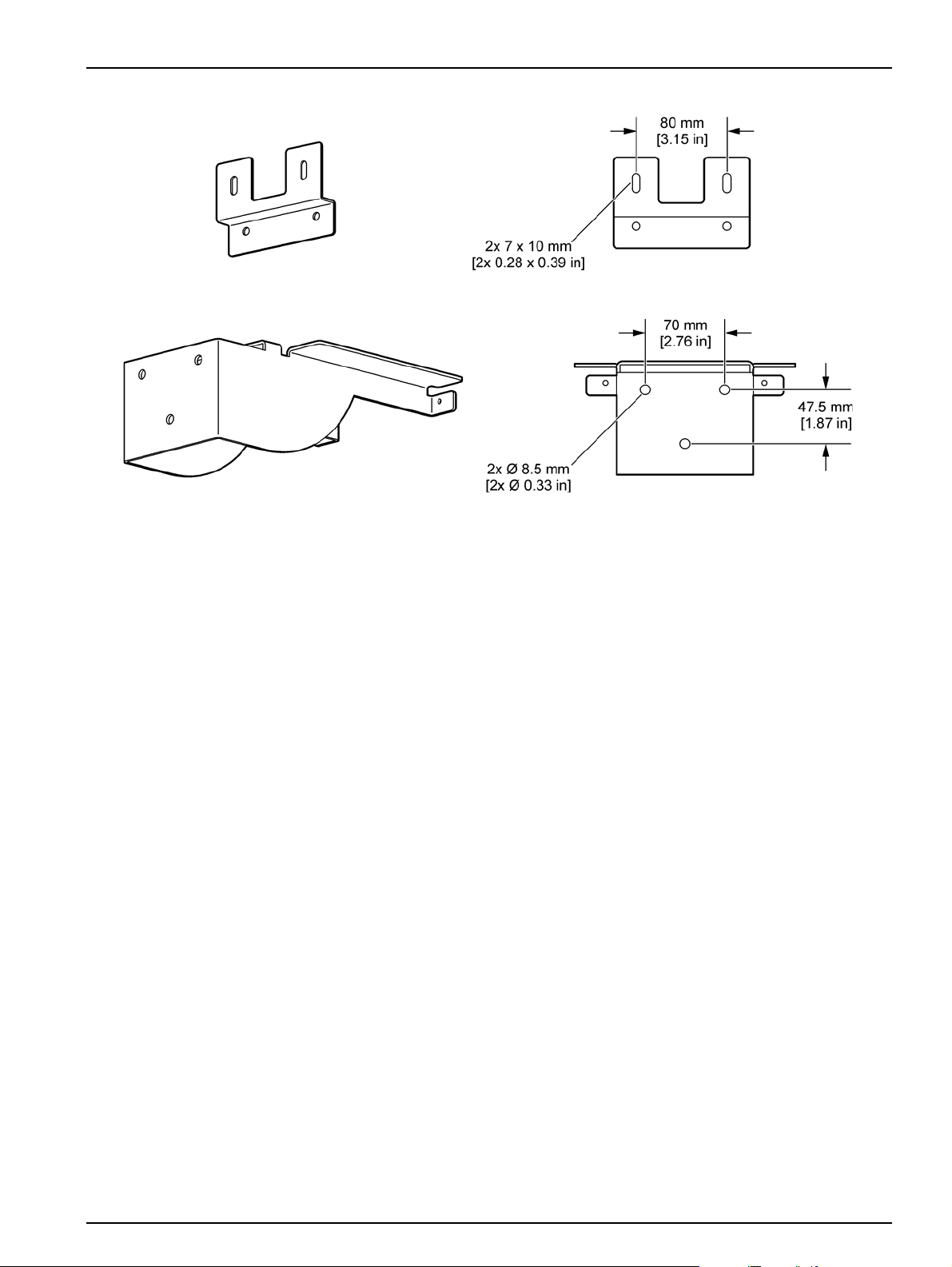
3.3.1.1 Wall mount
• Stand Mount; refer to the instruction sheet supplied with the
Stand Mounting Hardware.
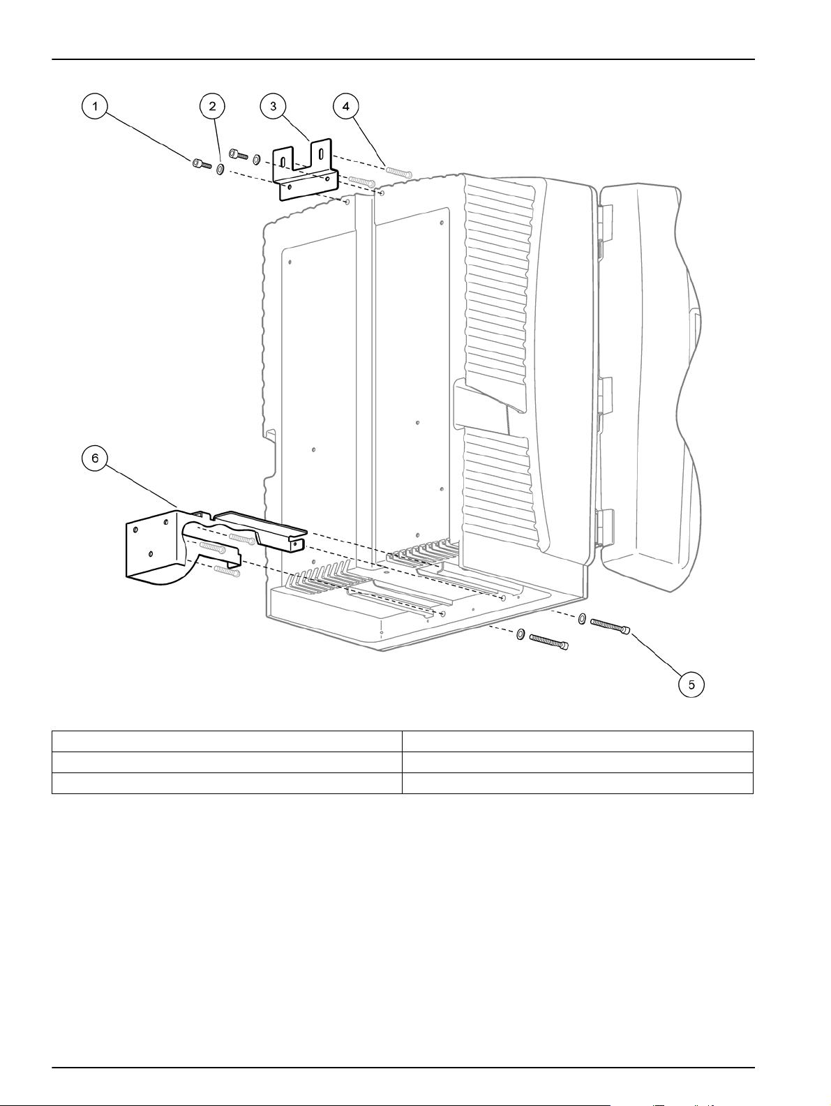
Refer to Figure 5, Figure 6, and following instructions to mount the
analyzer to a wall.
1. Align and install the fastening bracket to the wall.
2. Attach the angle bracket to the instrument using the
supplied screws.
3. Slide the bottom of the enclosure onto the fastening bracket.
4. Attach the enclosure to the fastening bracket.
5. Attach the angle bracket on the enclosure to the wall.
14
Page 15
Installation
Figure 5 Bracket dimensions for wall mounting
15
Page 16
Installation
Figure 6 Wall mounting the analyzer
1 Washer, M5 (4X) 4 Screw, customer supplied
2 Socket head cap screw, M5 X 8 (2X) 5 Socket head cap screw, M5 X 40 (2X)
3 Angle bracket 6 Fastening bracket
16
Page 17
3.4 Initial instrument setup
3.4.1 Open the enclosure
Installation
DANGER
To reduce the risk of electrica l shock, mak e sure tha t no water
can enter the enclosure or come into contact with circuit
boards.
CAUTION
The enclosure may tip forwards if it has not been fixed in
place. Only open the enclosure if the enclosure is properly
mounted.
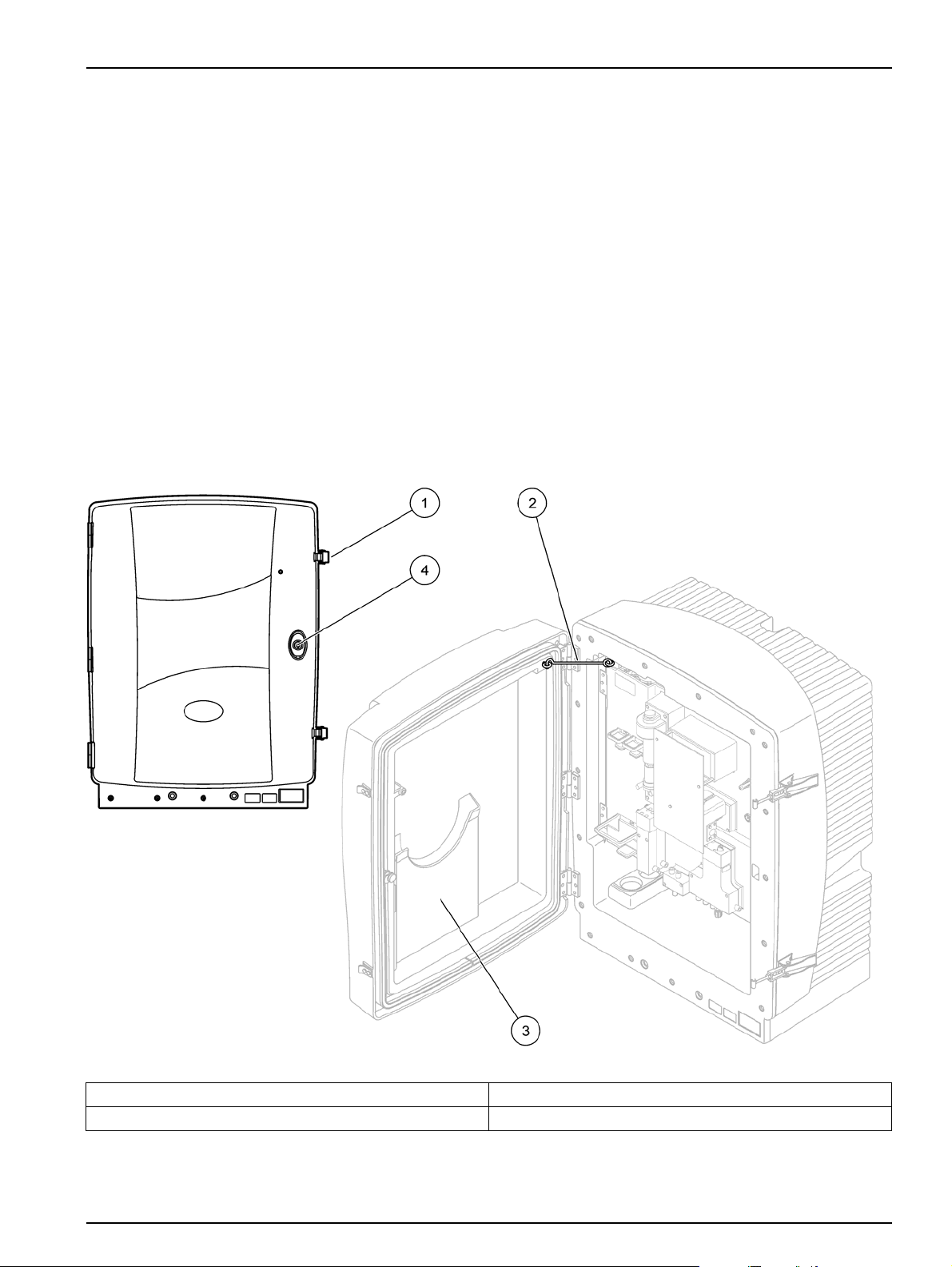
1. Unlock the instrument (item 4, Figure 7, item 3, Figure 8).
2. Open the side latches and release the door catch.
3. Open the door and secure the door using the hook or
completely remove the door.
Figure 7 Open the PHOSPHAX sc enclosure
1 Latches 3 Pocket for manual
2 Door hook 4 Lock with key
17
Page 18

Installation
1
3
2
Figure 8 Open the PHOSPHAX indoor sc enclosure
1 Latches 3 Lock with key
2 Door hook
18
Page 19
3.4.2 Remove the shipping transport locks
Prior to system start-up, the shipping transport locks must be
removed from the sc analyzer.
CAUTION
The enclosure may tip forwards if it has not been fixed in
place. Only open the enclosure if the enclosure is properly
mounted.
Important note: The cuvette insulation for the measuring unit is
NOT a transport lock. Do NOT remove the cover on the measuring
unit.
1. Open the enclosure door and secure with the door hook.
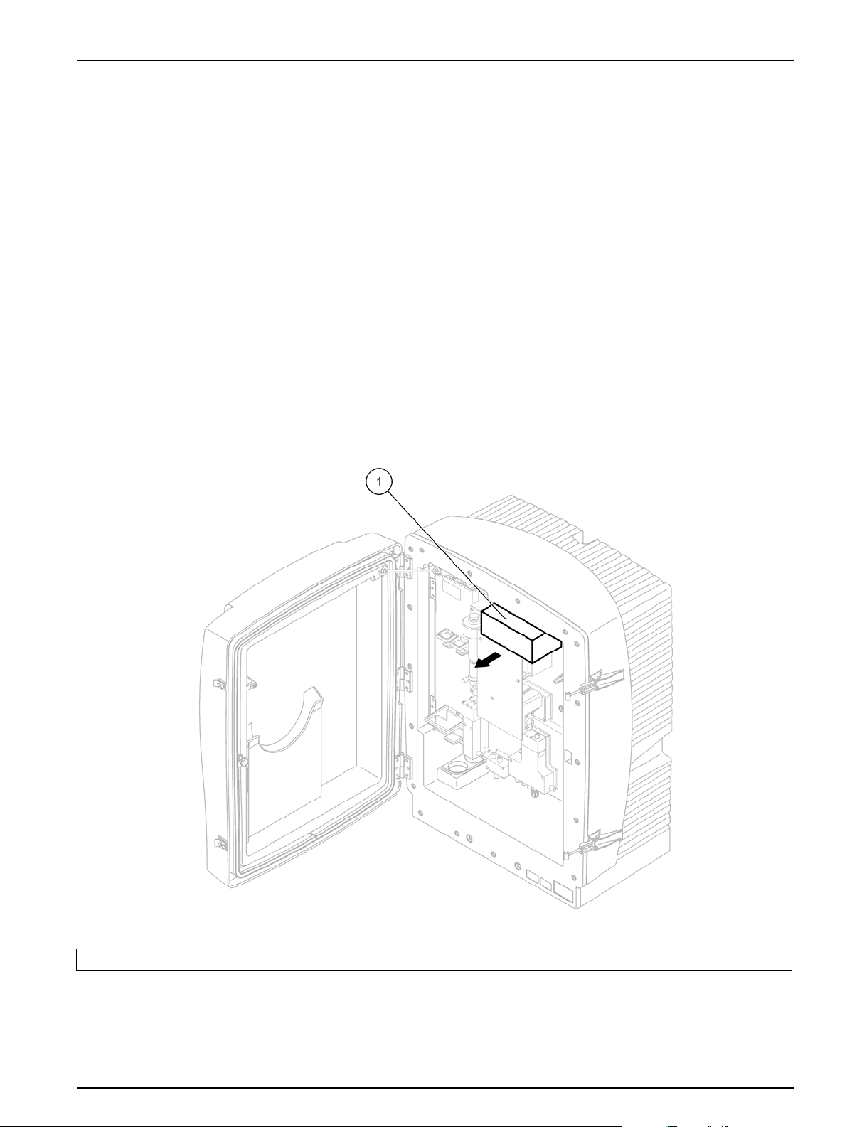
2. Remove the transport lock on the analyzer panel (Figure 9).
Note: If the instrument is operated with a Filter Probe sc, it is equipped
with an internal compressor.
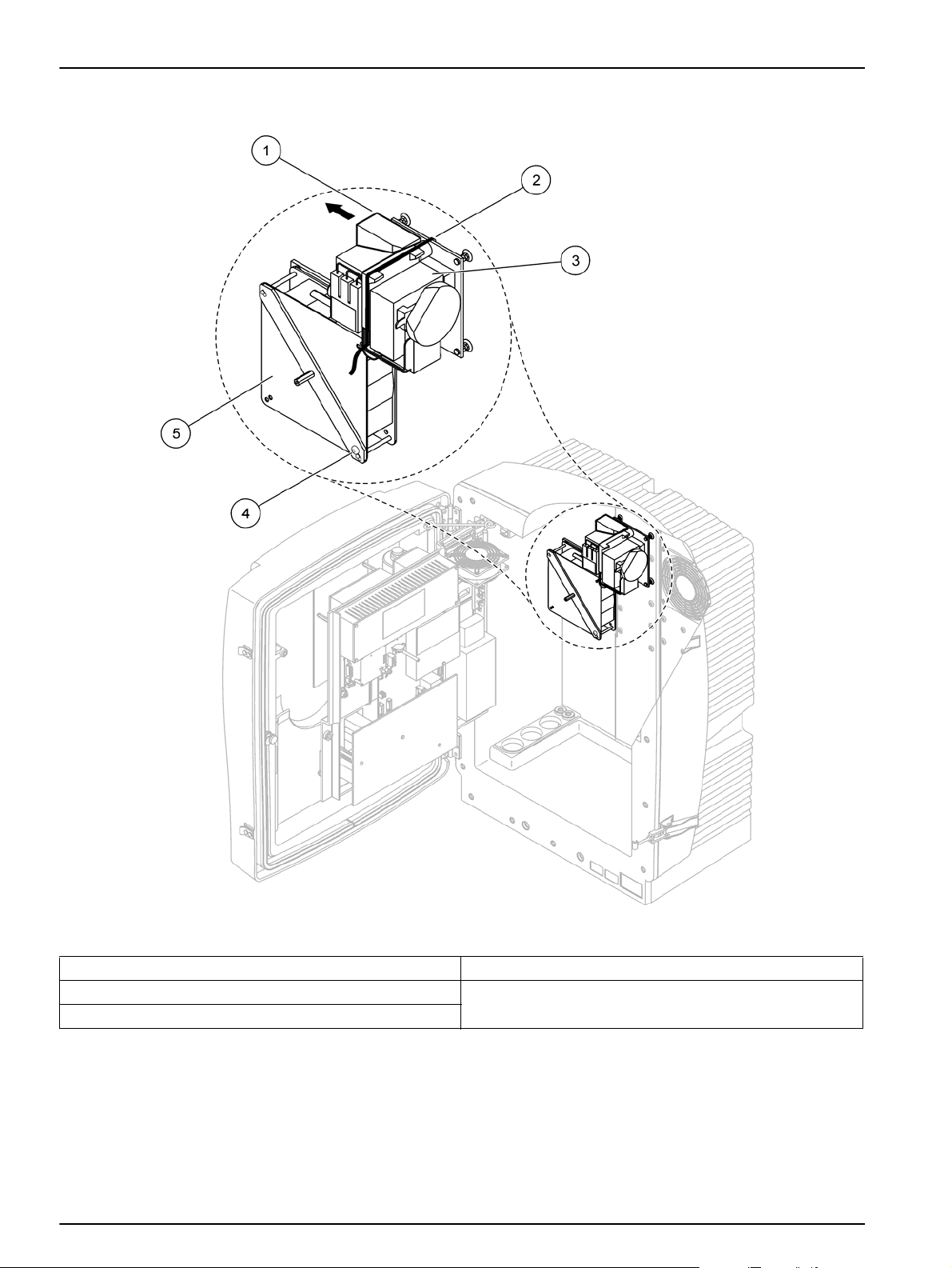
3. Remove the cable tie and pull out the compressor transport
lock to the left (Figure 10).
Note: Keep the transport locks for transporting and storage.
Installation
1 Transport lock
Figure 9 Remove the analyzer panel transport locks
19
Page 20
Installation
3.4.3 Installation of the collecting tray
Figure 10 Remove the compressor transport lock
1 Compressor transport lock 4 Fan locking screw
2 Cable tie 5 Fan
3 Compressor
1
The compressor, compressor transport lock, and cable tie only apply to sc analyzers that operate using the Filter Probe sc.
1
20
Page 21
Installation
CAUTION
The enclosure may tip forwards if it has not been fixed in
place. Only open the enclosure if the enclosure is properly
mounted.
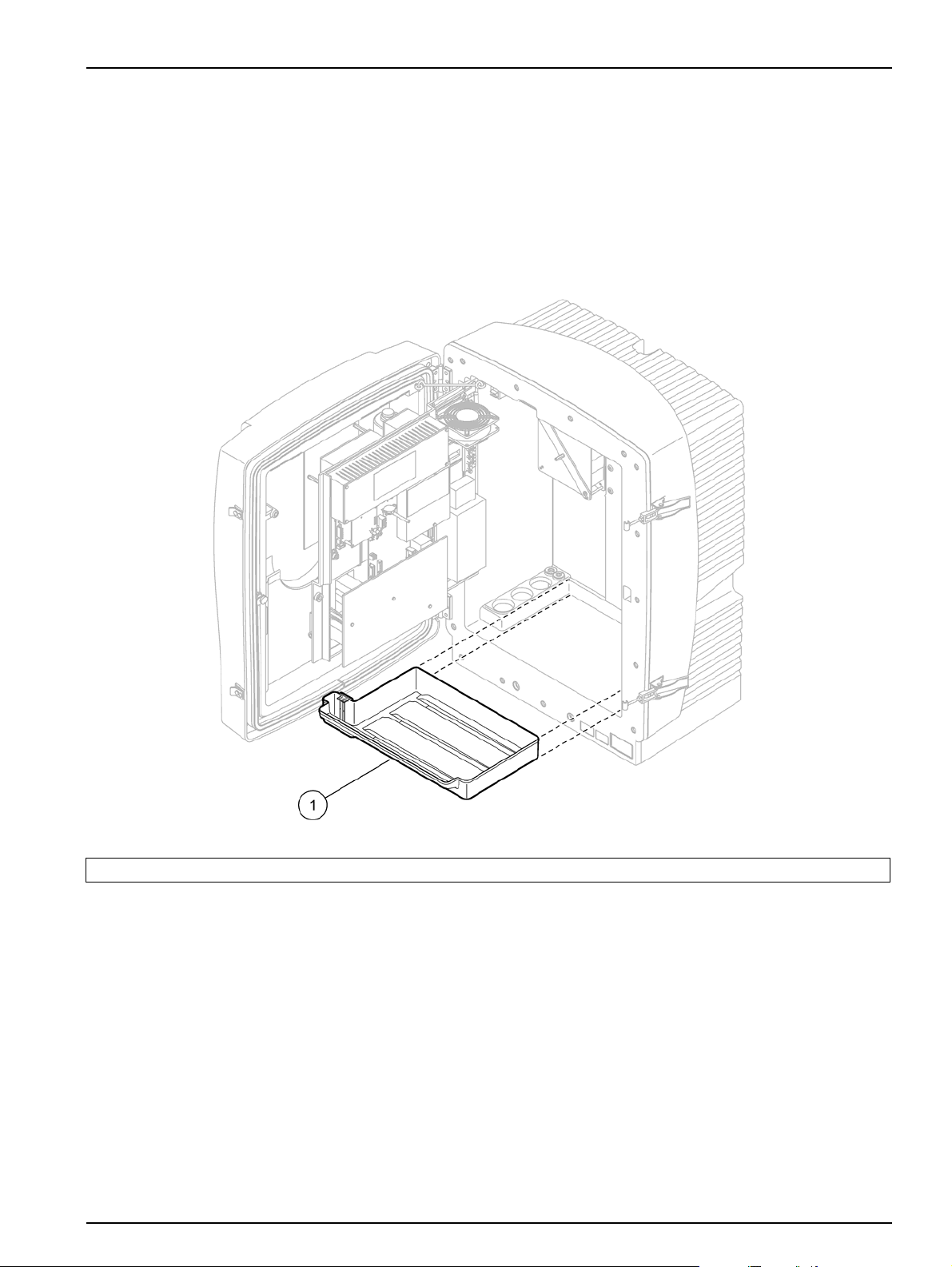
1. Open the enclosure door and secure with the door hook.
2. Slide the collecting tray into the bottom of the enclosure
(Figure 11).
1 Collecting tray
Figure 11 Installation of the collecting tray
21
Page 22
Installation
3.4.4 Connect the humidity sensor
CAUTION
The enclosure may tip forwards if it has not been fixed in
place. Only open the enclosure if the enclosure is properly
mounted.
1. Remove power from the instrument.
2. Open the enclosure door and secure with the door hook.
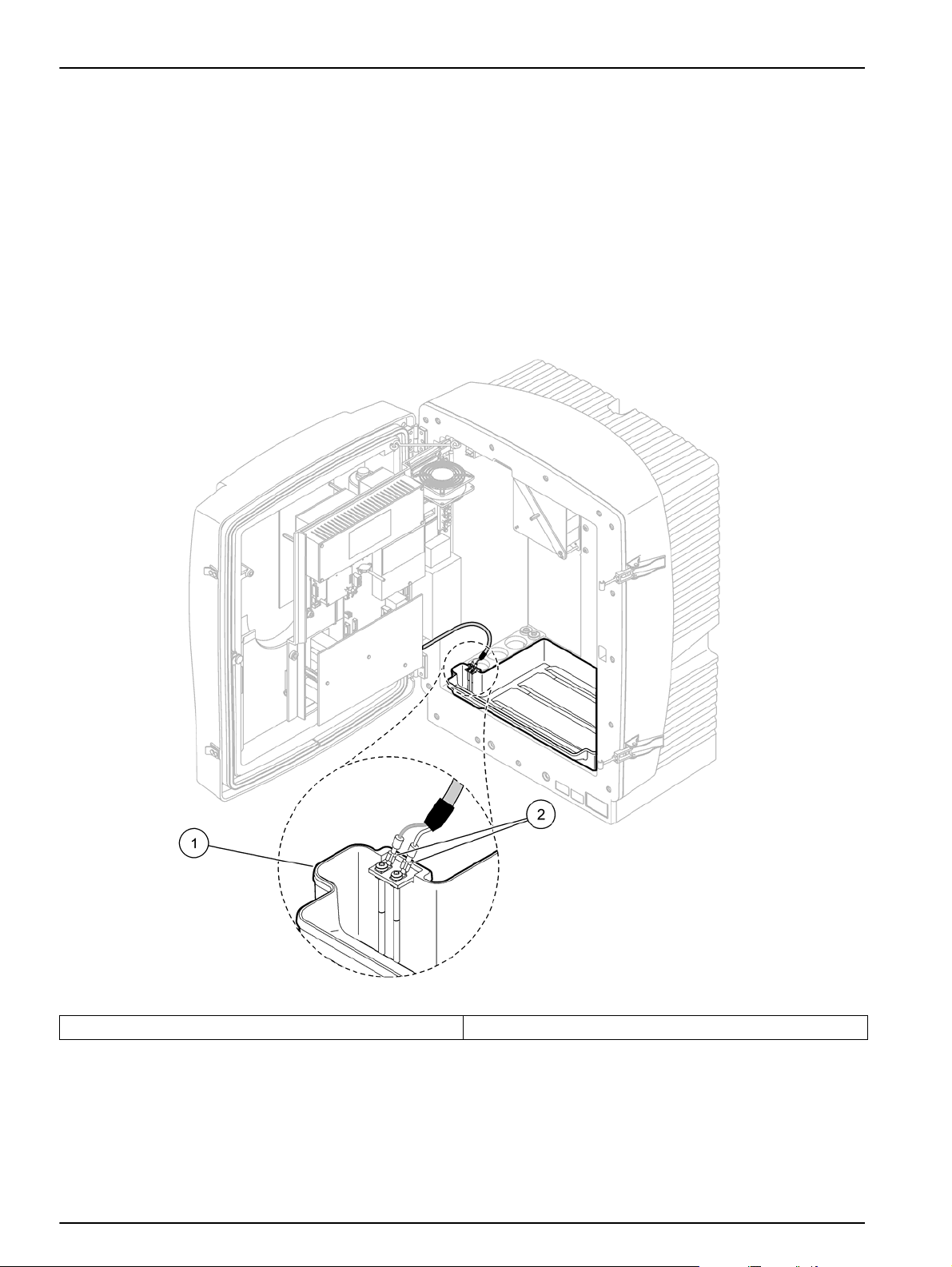
3. Connect the humidity sensor wires to the terminal screws on
the collecting tray (Figure 12).
Figure 12 Connect the humidity sensor
1 Collecting tray 2 Humidity sensor connections
22
Page 23
3.4.5 Connect the sample supplies and drain
Before connecting tubing or cables, determine the option number
that corresponds the system configuration. Refer to Table 1. Based
on the option number, determine the sealing plug that will be used
to seal the enclosure openings, refer to Table 2.
When the option number is determined, refer to Appendix A
Plumbing and connection options on page 65 for installation
information.
Table 1 System configuration options
Installation
Location Filtration Drain
Filter Probe sc Any 1 1 1 1 A.5 on page 68
Filter Probe sc Heated 1 1 1 2 A.6, page 70
OUTDOOR
INDOOR
1
For 2-parameter options, refer to Connect a 2-parameter option on page 66.
FILTRAX Heated 1 1 1 3 A.7, page 72
FILTRAX 2 heated 2 1 2 4 A.8, page 74
2 FILTRAX Heated 1 2 1 5 A.9, page 77
2 FILTRAX 2 heated 2 2 2 6 A.10, page 79
Filter Probe sc Unheated 1 1 1 7 A.11, page 81
FILTRAX Unheated
2 FILTRAX Unheated
Continuous
sample feed
2 continuous
sample feeds
Unheated
Unheated
Number of
analyzers
11 18 aA.12, page 83
21 28 bA.13, page 85
12 19 aA.14, page 87
22 29 bA.15, page 89
11 110 aA.16, page 91
22 210 bA.17, page 93
12 111 aA.18, page 95
22 211 bA.19, page 97
Sample
lines
(Ch1, Ch2)
Number of
parameters
Option
1
Refer to the following section
#
for more information:
Table 2 Sealing plug types
Analyzer 1 Analyzer 2
Option
Opening 1 Opening 2 Opening 3 Opening 1 Opening 2 Opening 3
1 Plug 2 Plug 3 Plug 3 — — —
2 Plug 2 Plug 1 Plug 3 — — —
3 Plug 1 Plug 1 Plug 3 — — —
4 Plug 1 Plug 1 Plug 3 Plug 1 Plug 1 Plug 3
5 Plug 1 Plug 1 Plug 1 — — —
6 Plug 1 Plug 1 Plug 1 Plug 1 Plug 1 Plug 3
7 Plug 2 Plug 3 Plug 3 — — —
8 Plug 1 Plug 3 Plug 3 Plug 3 Plug 3 Plug 3
9 Plug 1 Plug 1 Plug 3 Plug 3 Plug 3 Plug 3
10 Plug 3 Plug 3 Plug 3 Plug 3 Plug 3 Plug 3
11 Plug 3 Plug 3 Plug 3 Plug 3 Plug 3 Plug 3
23
Page 24
Installation
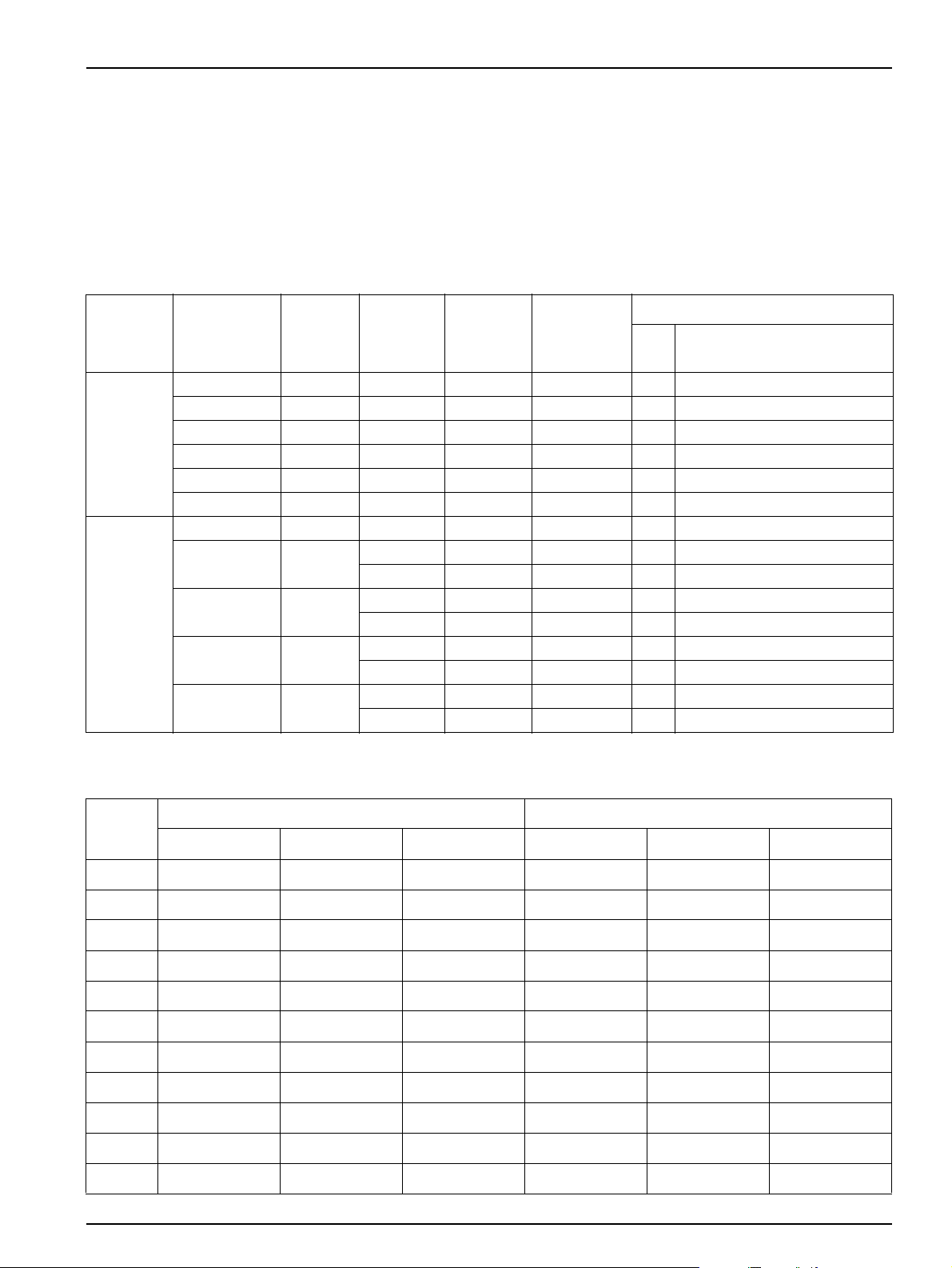
Figure 13 Sealing plug types
1 Sealing plug type 1
2 Sealing plug type 2
3 Sealing plug type 3
3.5 Electrical installation
DANGER
High voltage wiring connections are present under the
protective cover. The protective cover must remain in place
unless a qualified installation technician is installing wiring for
the Filter Probe sc or the heated drain.
See Figure 14 for protective cover removal.
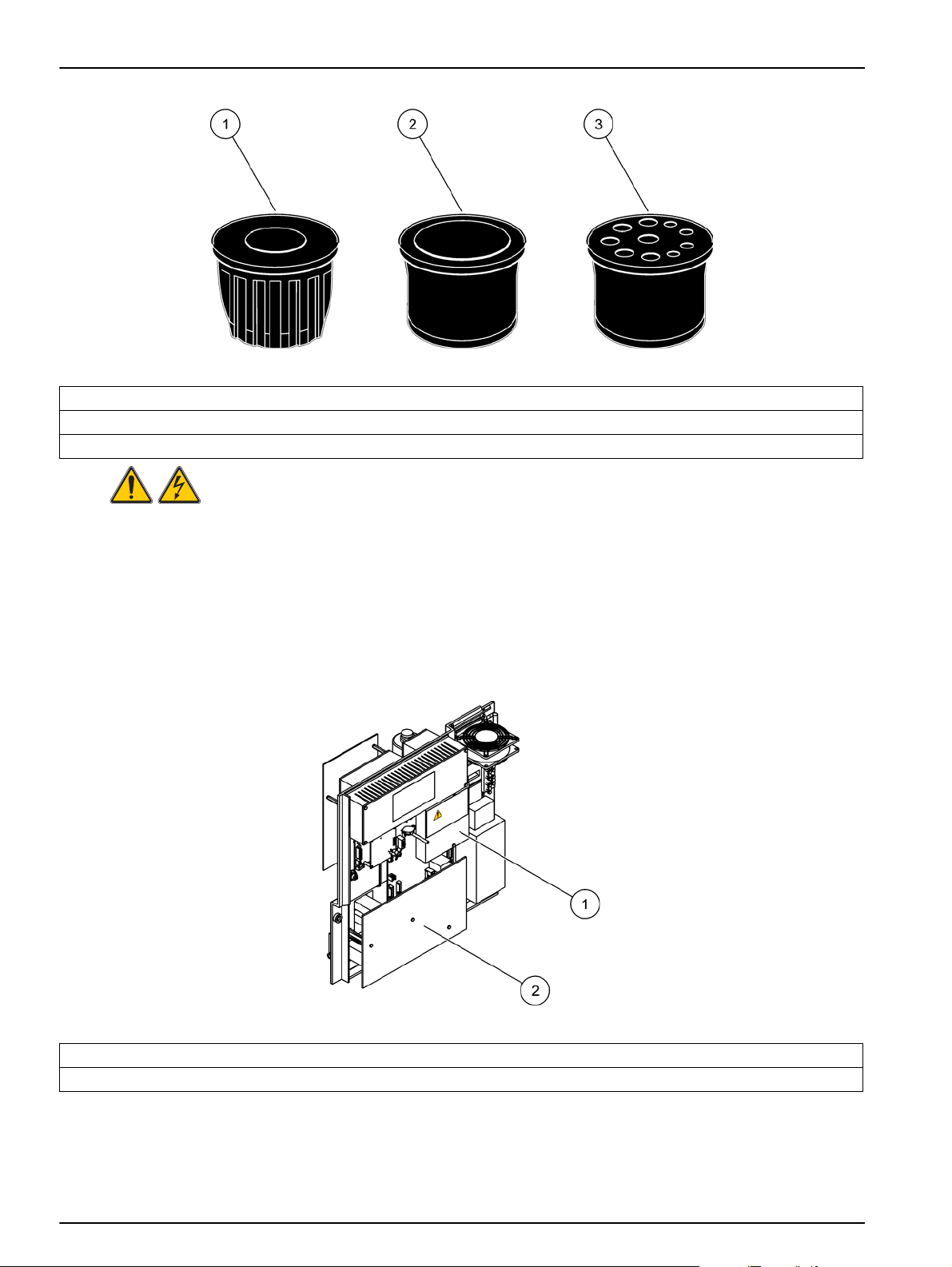
Figure 14 Remove the protective covers
1 Protective cover for AC mains circuits (Back view)
2 Bottom protective cover for main PCB
24
Page 25
3.5.1 Electrostatic Discharge (ESD) Considerations
Important Note: To minimize hazards an d ESD risks, maintenance
procedures not requiring power to the analyzer should be
performed with power removed.
Delicate internal electronic components can be damaged by static
electricity, resulting in degraded instrument performance or
eventual failure.
The manufacturer recommends taking the following steps to
prevent ESD damage to the instrument:
• Before touching any instrument electronic components (such
as printed circuit cards and the components on them)
discharge static electricity. This can be accomplished by
touching an earth-grounded metal surface such as the chassis
of an instrument or pipe or a metal conduit.
• To reduce static build-up, avoid excessive movement.
Transport static-sensitive components in anti-static containers
or packaging.
• To discharge static electricity and keep it discharged, wear a
wrist strap connected by a wire to earth ground.
Installation
3.5.2 Enclosure breakouts
• Handle all static-sensitive components in a static-safe area. If
possible, use anti-static floor pads and work bench pads.
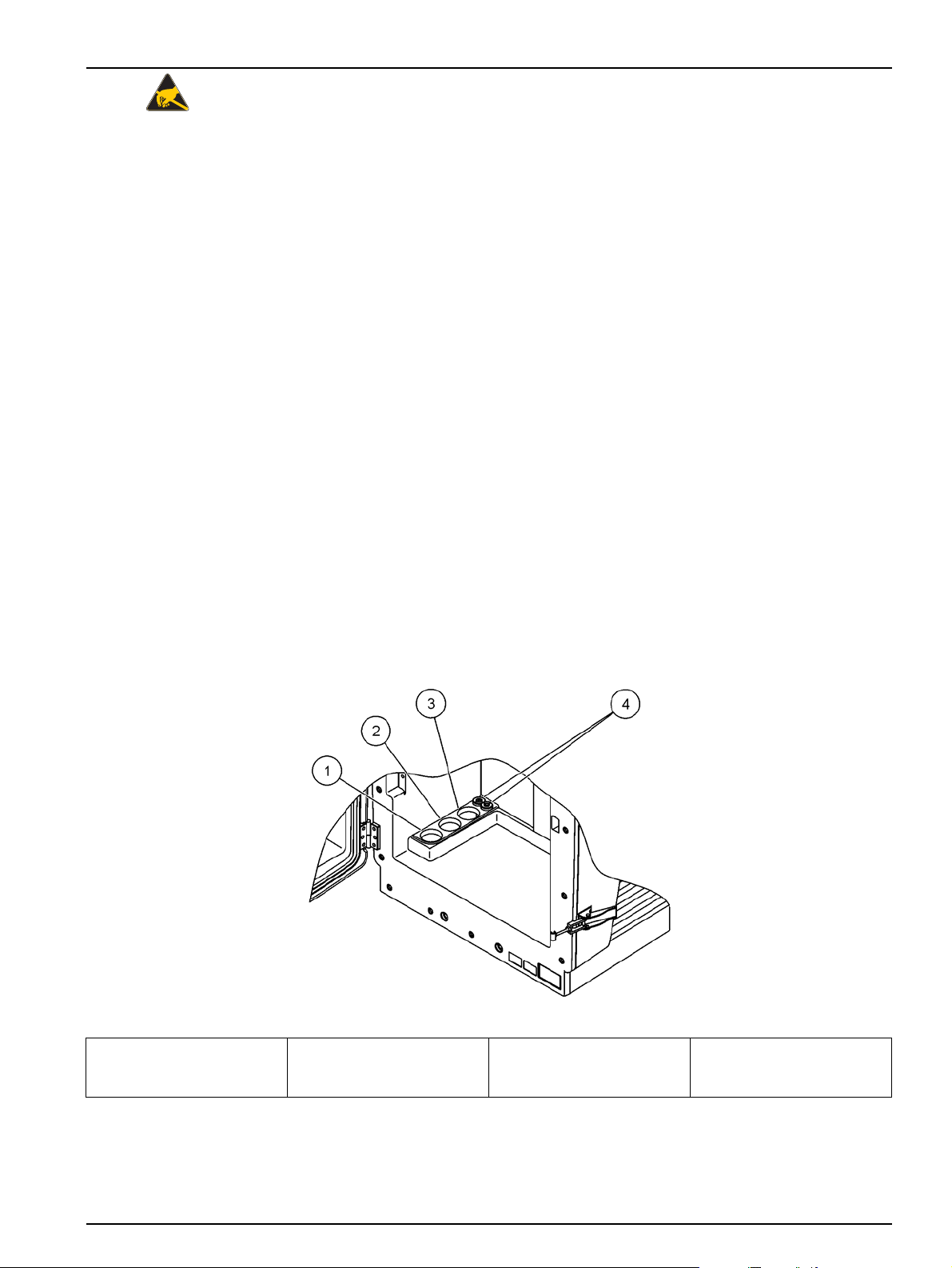
There are four main enclosure openings to insert tubing and cables
(Figure 15).
1 Sample feed or refer to
Table 1, page 23 for
tubing options.
Figure 15 Enclosure breakouts
2 Refer to Table 1,
page 23 for tubing
options.
3 Refer to Table 1,
page 23 for tubing
options.
4 Power and data cables
25
Page 26
Installation
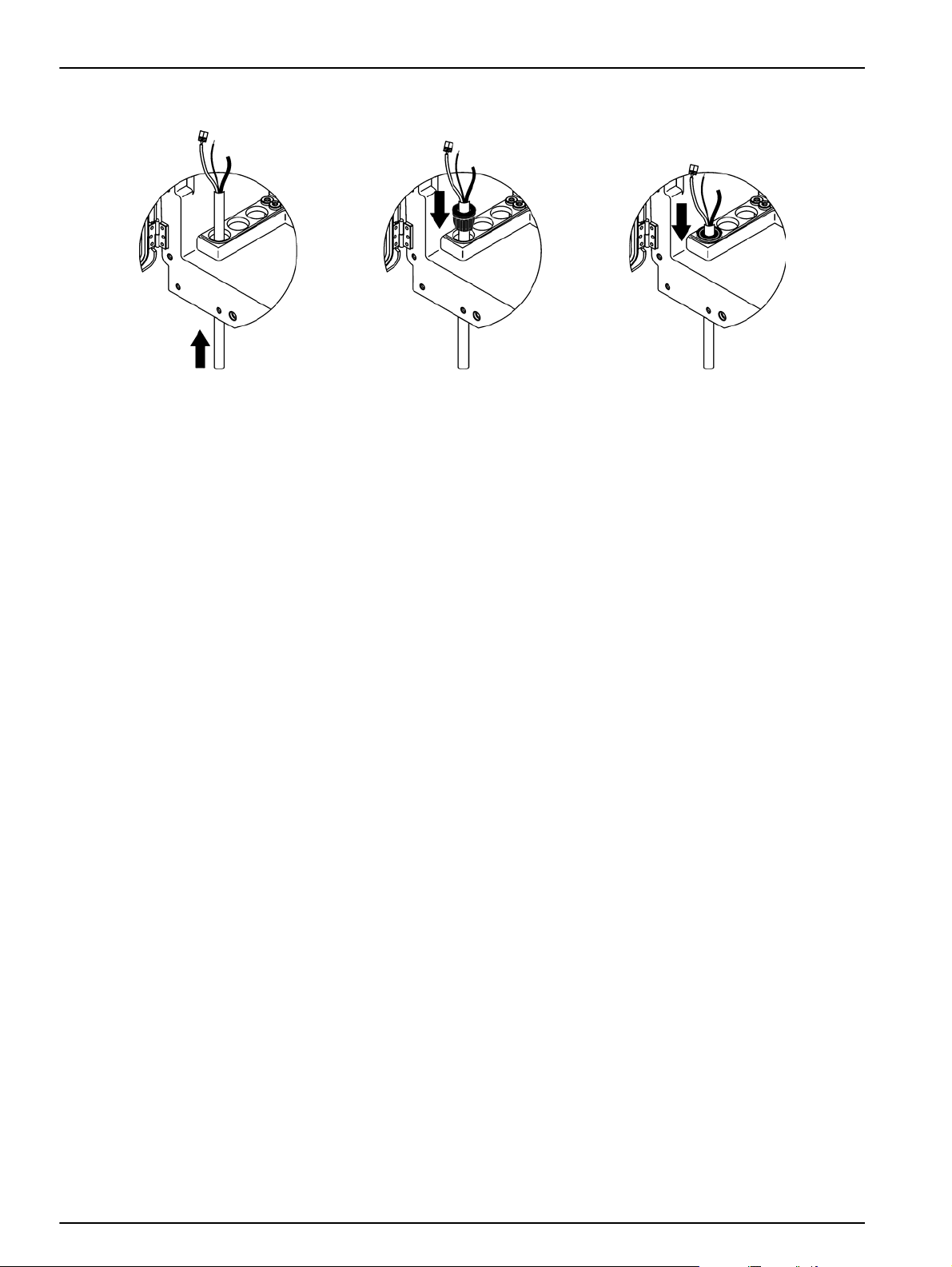
3.5.3 Insert tubing and/or cables
1 Guide the tubing or cables through
the enclosure openings
(Figure 15).
2 Push the plug from the top onto the
tubing or onto the cable.
3.5.4 Connect the Filter Probe sc to the analyzer (optional)
CAUTION
The enclosure may tip forwards if it has not been fixed in
place. Only open the enclosure if the enclosure is properly
mounted.
DANGER
Disconnect power from the sc analyzer at the sc1000 before
removing the protective covers in the an aly ze r.
Important Note: Make sure that for the use of a filter probe, the
level of the water in which the filtration probe is submersed, is
below the level of the analyzer.
1. Open the enclosure door and secure with the door hook.
2. Open the analyzer panel.
3. Remove the two screws from the protective cover and remove
the cover (item 1, Figure 14, page 24).
4. Connect the earth ground (green/yellow) wire (item 9, Figure 16
on page 28) from the Filter Probe sc to the ground terminal
(item 5, Figure 16 on page 28).
3 Pull down the plug with the tubing
or the cables. Seal any unused
entry with Plug #3.
26
5. Connect the power connector to the appropriate terminal
connection (items 4 and 11, Figure 16 on page 28).
6. Remove the three screws securing the bottom panel cover
(item 2, Figure 14, page 24). Remove the panel.
7. Connect the data connector (item 10, Figure 16 on page 28) to
the main board (item 12, Figure 16 on page 28).
8. Install all covers and panels.
9. Connect the white air tubing (item 8, Figure 16 on page 28)
from the Filter Probe sc to the air tubing connection on the
analyzer (Figure 16 on page 28).
10. For sample and drain line connections refer to A.5 on page 68.
Page 27

3.5.5 Connect the optional heated drain
CAUTION
The enclosure may tip forwards if it has not been fixed in
place. Only open the enclosure if the enclosure is properly
mounted.
DANGER
Disconnect power from the sc analyzer at the sc1000 before
removing the protective covers in the analyzer.
Refer to Figure 16 and the following procedure to connect the
heated drain.
1. Open the enclosure door and secure with the door hook.
2. Open the analyzer panel.
3. Remove the protective cover (Figure 14, page 24).
4. Connect the earth ground wire (green/yellow) to the ground
5. Connect the cables for the heated drain (item 6, Figure 16 on
6. Connect the drain tube as described in the appropriate Option
Installation
wire terminal strip.
page 28) to the terminal block (item 3, Figure 16 on page 28).
Configuration. Refer to Plumbing and connection options on
page 65 for more information.
7. Place the drain tube to the appropriate drain or basin.
8. Install all covers and panels.
27
Page 28
Installation
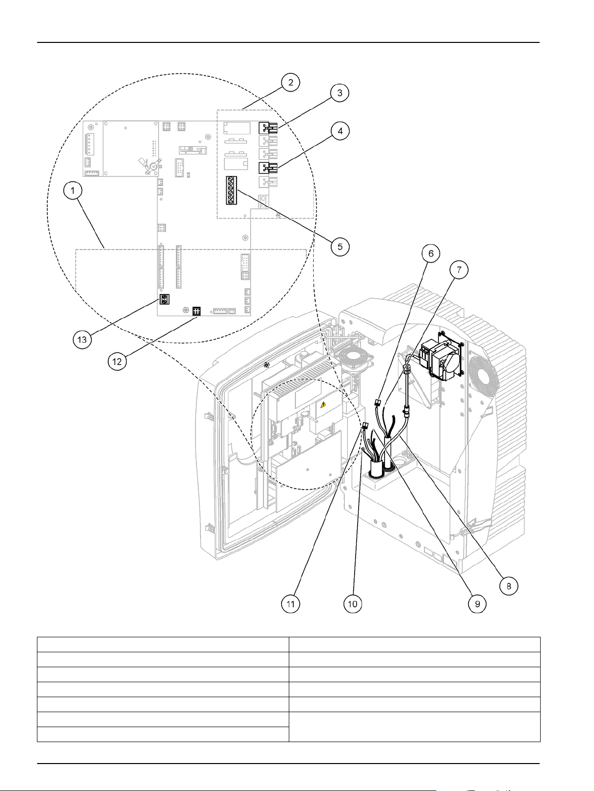
Figure 16 Connect the Filter Probe sc and optional heated drain
1 Bottom panel cover 8 Filter Probe sc air tube (white)
2 Protective cover 9 Filter Probe sc ground wire
3 Heated drain (optional) power connector 10 Filter Probe sc data cable connector
4 Filter Probe sc power connector 11 Filter Probe sc power cable connector
5 Earth ground wire terminal strip 12 Filter Probe sc data connector
6 Heated drain power cable connector 13 Remote control input (15–30 V DC) (Refer to section B.3,
7 Heated drain ground wire
page 100)
28
Page 29

3.6 Installation of reagents
Installation
CAUTION
Good safety habits and technique should be observed at all
times. Review all SDS/MSDS information and use
recommended safety measures to prevent exposure to
potential chemical hazards.
CAUTION
Avoid unnecessary contact with sample flows of unknown
concentration as they can produce hazards due to trace
chemicals, radiation, or biological effects.
CAUTION
The enclosure may tip forwards if it has not been fixed in
place. Only open the enclosure if the enclosure is properly
mounted.
Important Note: Always lay the drain tubing so that there is a
continuous fall (minimum 3°), the outlet is clear (not pressurized)
and, the drain tubing is not longer than 2 meters. For more
information refer to Appendix A on page 65.
Important Note: Incorrect use of the reagents can damage the
instrument. Carefully read the labels on the containers to ensure
there are no mistakes.
1. Place the reagent containers in the instrument (Figure 17).
2. Insert the tubing in the reagent containers.
Note: If the tubing connections are twisted, no chemicals will flow
through the connection and the instrument will not work correctly. Turn
the bottle while holding the lid still so that the tubing connections are
not twisted.
3. Screw the reagents to the caps supplied.
29
Page 30
Installation
Figure 17 Chemicals and reagents in the PHOSPHAX sc (section 8.1, page 51)
1 Connection to colorimeter (detector) 4 Reagent
2 Drain 5 Cleaning solution
3 Sample line
30
Page 31

3.7 Supply power to the analyzer
DANGER
Only connect the PHOSPHAX sc to the sc1000 power supply
when the instrument is completely wired internally and it is
correctly earthed.
DANGER
Always connect a ground fault interrupt circuit (GFIC) or a
residual current circuit breaker (trigger current maximum at
30 mA) between the main power supply and the sc1000.
DANGER
Do not use the power sockets on controllers as general
mains sockets. They are only designed to provide power for
the analyzers.
Important Note: Unless the sc1000 that connects to the
PHOSPHAX sc analyzer is already fitted with ac mains overvoltage
(surge) protection device, surge pr ot ect ion mu st be pro vid ed
between the mains connection of the sc1000 and the
PHOSPHAX sc analyzer if it is demanded by the local regulation.
Installation
Only supply power to the instrument after all plumbing connections,
reagent installations, and system start-up procedures have been
completed.
sc1000 power sockets can only be connected if a wide range
115/230 V power supply is built into the sc1000 controller. This
does not work with 24 V versions of the sc1000 because it does not
provide the appropriate connectors for the analyzers.
Refer to the sc1000 manual for more information on
connecting power.
1. Remove the power socket from the sc controller.
2. Connect the plug from the PHOSPHAX sc to the power socket
on the sc controller.
31
Page 32

Installation
Figure 18 Connect the PHOSPHAX sc to the sc1000 power supply
1 Data network connector
2 Power connectors
3.8 Connect the data network
Refer to the sc1000 controller user manual for more information on
connecting the Data Network (item 1, Figure 18).
32
Page 33

Section 4 System Startup
4.1 Initializing the instrument
Important Note: The instrument only can work correctly if it is at
operating temperature. Let the instrument warm up for a minimum
of an hour so the inside of the enclosure, chemicals and electrode
are at operating temperature.
1. Make sure the PHOSPHAX sc is registered in the sc1000
system. If necessary, initiate the controller to search for the
analyzer. Refer to the sc1000 user manual for more
information.
2. Configure the analyzer in the SENSOR SETUP menu and note
the settings. Refer to section 5.2 on page 35 for more
information. The factory settings (default setting) are
appropriate for most typical applications.
3. From SENSOR SETUP, select
PHOSPHAX sc>MAINTENANCE>TEST/MAIN.
4. Select the PREPUMP ALL function and confirm.
5. Wait until the analyzer returns to the service state (displayed in
TEST/MAIN.>PROCESS) after the prepumping sequence is
completed.
6. Select START from the maintenance menu.
33
Page 34

System Startup
34
Page 35

Section 5 Operation
The PHOSPHAX sc can only be operated with an sc1000
controller. Refer to the sc1000 user manual for more information.
An LED on the door (works with door open and closed) indicates
the current operating state. Refer to the sc1000 User Manual and
section 7.2.1 on page 47.
5.1 Sensor diagnostics menu
SELECT PHOSPHAX sc (if more than one sensor or analyzer is attached)
PHOSPHAX sc
ERROR LIST Displays all errors currently present in the sensor
WARNING LIST Displays all warnings currently present in the sensor
5.2 Sensor setup menu
SELECT PHOSPHAX sc (if more than one sensor or analyzer is attached)
CALIBRATION
CORR. FACTOR Displays the locations and correction factors
LOCATION1 Displays location1 from CONFIGURE
GAIN CORR sets correction factor for channel 1
LOCATION2 On 2-channel version
GAIN CORR On 2-channel version
INTRINS. COLOR Displays the zero extinction
EXT. FACTOR Displays the internal device factor
OFFSET can be used to slightly correct measurements which are close to Zero
DEFAULT SETUP Resets the user-editable options to their factory-defaults
CONFIGURE
LOCATION 1 Settings for location 1
EDIT NAME Enter the name for the measuring location as required.
SET PARAMETER Output can be set as phosphate or phosphate-phosphor.
SELECT UNITS Output in mg/lL or ppm.
QUANTITY CH 1
DISCHARGE VAL 1
LOCATION 2 Settings for location 2
EDIT NAME Enter the name for the measuring location as required (on 2-channel version).
SET PARAMETER Output can be set as phosphate or phosphate-phosphor (on 2-channel version).
SELECT UNITS Output in mg/l or ppm (on 2-channel version).
QUANTITY CH 2
DISCHARGE VAL 2
Number of measurements in succession ( = measurements on channel 1 +
DISCHARGE VAL 1 channel 1). Available with the 2-channel version.
Number of discarded values after switching from channel 1 to channel 2. Available with the
2-channel version.
Number of measurements in succession ( = measurements on channel 2 +
DISCHARGE VAL 2 channel 2). Available with the 2-channel version.
Number of discarded values after switching from channel 2 to channel 1. Available with the
2-channel version.
35
Page 36

Operation
5.2 Sensor setup menu (continued)
CONFIGURE (continued)
MEASURING
Enter how often measurements are to be taken. ATTENTION with filtration probe and 5min
SET INTERVAL
SET TO
START BY BUS:
START BY BUS:
NUMBER OF MEAS.: Number of measurements that are taken after one activation by bus.
DISCHARGE: Number of discharged values that precedes the measurements.
AVERAGE: Number of measurements that are averaged. (effects bus triggered measurements only)
CLEANING
SET INTERVAL Number of hours between the cleanings.
START
DISCHARGE Number of measured values that are discarded after a cleaning operation.
SET OUTMODE
TUBE HEATING
ON Probe tube heating switches on at the start of the selected month. With filtration probe.
OFF Probe tube heating switches off at the end of the selected month. With filtration probe.
REAG. WARNING
REAG. WARNING ON/OFF: On determines the warning output if the reagent levels are low.
WARNING Determines the level below which the reagent must drop to trigger the warning.
STAT. MODUL.WAR.
40 %, 30 %, 15 %
STATUS MODUL.ERR
14 %,10 %,8 %, OFF
SAMPLE DETECTION
OFF/WARNING/ERROR
EXHAUST CONTROL
ON/OFF Determines instrument reaction when drain is blocked
REF
ON/OFF Determines if measurement reference channel is used for measurement or not.
BUBBLE REJECT
ON/OFF
operation: increased pump speed in the filtration probe, annual filtration probe maintenance is
necessary instead of every 2 years.
WET/DRY, decides if the cuvette is empty (DRY) or filled (WET) between measurements at
measurement intervals that are equal or greater than 10 minutes. Adapt individually for
smoothest measurement values.
YES/NO, decides if the instrument is measuring continuously or measurements are triggered
by field-bus. The "Fieldbus" option must be activated in the TEST/MAINT menu. The
instrument will switch to a 5 min interval when activated.
Start time for the cleaning (in case of more than one cleaning per day: start time for the first
cleaning)
Value output during a cleaning operation and the following discarded values. HOLD = last
measured value, SET TRANSFER = value to be entered
Warning is released, when a filter probe is installed and the status of filtration modules falls
below the defined level.
Status of filtration modules at filter probe at which an error is generated. When switched to
OFF, a deactivated sample detection will be switched to "warning".
Determines instruments reaction when amount of available sample is to low. When
instrument is in filter probe mode, deactivating the sample detection will switch a deactivated
"STATUS MODUL.ERR" to 14 %
Use for samples that produce gas when acid is added. If active, sample is removed from
cuvette after reagent has been added, then refilled again to remove bubbles. If active, the
measurement interval of 5 minutes is not available. For not degassing samples the
measurement values are smother with bubble rejection deactivated.
36
Page 37

5.2 Sensor setup menu (continued)
CONFIGURE (continued)
DEFAULT SETUP Prompt as to whether the factory settings are to be re-applied.
LAST CHANGE Indication of the last change to a setting on the configuration menu.
MAINTENANCE
INFORMATION
LOCATION 1 Indication of measuring location 1
LOCATION 2 Indication of measuring location 2 (on two-channel version)
TYPE Indication of instrument type
SENSOR NAME Indication of instrument name
SERIAL NUMBER Indication of serial number
RANGE Indication of measuring range
OPTION Indication of instrument option (filtration probe/1-channel/2-channel)
SOFTWARE PROBE Filtration probe software (on filtration probe operation)
SOFTWARE PHOS. Instrument software
LOADER Detailed information on the software in the instrument
APPL Detailed information on the software in the instrument
STRUCTURE Detailed information on the software in the instrument
FIRMWARE Detailed information on the software in the instrument
CONTENT Detailed information on the software in the instrument
LANGUAGE List of languages that are supported by the installed language package.
MEASURING DATA
LOCATION1
GAIN CORR Indicates the correction factor set for correcting the measured values at measuring location 1.
DATE Indicates the date of the last change to the correction factor.
LOCATION2 On 2-channel version
GAIN CORR On 2-channel version
DATE On 2-channel version
DEXT LAST VALUE Indication of the delta extinction (EXT MESS-EXT REF) of the last measurement.
EXT MESS Extinction during the last measurement
EXT REF Extinction during the last zeroing
AMPLIFY MEAS. Measuring amplifier gain factor
AMPLIFY REF Reference amplifier gain factor
MEAS. ZERO Measuring amplifier measured value during zeroing
OFFSET MEAS. Measuring amplifier offset
MEAS. Measuring amplifier measured value during measurement
REF ZERO Reference amplifier measured value during zeroing
OFFSET REF Reference amplifier offset
REF Reference amplifier measured value during measurement
PROCESS Information what instrument is currently doing (measurement, calibration etc.)
REMAINING TIME Remaining time for current process, counting down to zero
LIST OF VALUES List of the last 10 measured values
Operation
37
Page 38

Operation
5.2 Sensor setup menu (continued)
MAINTENANCE (continued)
MAINT. COUNTER Counter for reagent and consumables
OPERATING HOURS Displays the instrument's operating hours.
REAGENT Displays the current level of the reagent.
CLEANING SOL. Displays the current level of the cleaning solution.
AIR FILTER PADS Days left until the next air filter change/clean.
PISTON PUMP Days left until the next pump piston and cylinder replacement (PHOSPHAX piston pump)
REAGENT PUMP Number of pump strokes performed by the reagent metering pump.
STATUS MODULES Displays the state of the modules (on filtration probe operation).
CLEANING MODULES Last filter module cleaning (on filtration probe operation).
NEW MODULES Last filter module replacement (on filtration probe operation).
PUMP MEMBRANE
COMPRESSOR Days left until the replacement of the air compressor (on filtration probe operation).
TEST/MAINT Maintenance processes
SIGNALS
PROCESS Indication of what the instrument is doing.
REMAINING TIME Indication of the time left for the currently ongoing process
CUVETTE TEMP. Current measuring cell temperature
ENCLOSURE TEMP Current temperature in the instrument
COOLING Current speed of the enclosure fan in %
HEATING Current enclosure heating power
PRESSURE ANALY Current pressure in the metering system of the valve block in mbar
HUMIDITY ANALY Indication of whether there is liquid in the collecting tray
STATUS MODULES Only if filtration probe is registered: shows status of filtration modules (0–100 %)
PRESSURE P. MIN
PRESSURE PROBE Only if filtration probe is registered: shows the actual minimum pressure at the filter modules
PROBE HEATING Only if filtration probe is registered: indication of switching state of sample tubing heating
HUMIDITY PROBE
DRAIN HEATING only in 1 or 2 channel mode: shows status of drain heating
PROCESS Indication of what the instrument is doing.
REMAINING TIME Indication of the time left for the currently ongoing process
SERVICE MODE
SET OUTMODE
START Leave service mode, start measurement
REAGENT Reset the maintenance counter after reagent change.
CLEANING SOL. Reset the maintenance counter after changing the cleaning solution.
AIR FILTER PADS Menu-based process for changing the air filter pads, resetting the maintenance counter.
PISTON PUMP
REAGENT PUMP
Date of the last pump membrane replacement (filtration probe sample pump) (on filtration
probe operation).
Only if filtration probe is registered :shows the averaged minimum pressure at the filter
modules
Only if filtration probe is registered: indication of whether there is moisture in the probe
enclosure
Instrument can be set to service mode, for example for maintenance (system free of liquids,
thermal management and compressor for filter probe (if installed) active)
Value that is output in the service state. HOLD=last measured value, SET TRANSFER= value
to be entered
Days left until the next pump piston and cylinder replacement (PHOSPHAX piston pump),
reset after replacement of the pump
Number of pump strokes performed by the reagent metering pump, reset after replacement of
the pump.
38
Page 39

5.2 Sensor setup menu (continued)
MAINTENANCE (continued)
PREPUMPING
PREPUMP ALL All liquids are pre-pumped in succession.
PREPUMP REAG. The reagent is pre-pumped.
PREPUMP CLEAN. The cleaning solution is pre-pumped.
PREPUMPING
PROBE
PREPUMP SAMPLE Only if filtration probe is registered: sample is pumped from the filtration probe for 1 minute
MODULE CLEAN.
NEW MODULES Only if filtration probe is registered: last filter module replacement.
PUMP MEMBRANE
COMPRESSOR Only if filtration probe is registered: days left until the replacement of the air compressor.
CLEANING Trigger an automatic cleaning, then start measurement
FLUSHING
RESET ERROR Reset all error messages
UPDATE PROBE Enables the filtration probe software to be updated.
FIELDBUS
OPTION
VAL IDATION
Only if filtration probe is registered: The filtration probe and modules are bled and
pre-pumped.
Menu-based process for cleaning the filter modules, automatically resetting the maintenance
counter. With filtration probe.
Only if filtration probe is registered: date of the last pump membrane replacement (filtration
probe sample pump).
Pumps all liquids in succession. Put all tubings that go to reagents, standards and cleaning
solutions into deionised water and start FLUSHING prior to taking instrument out of operation
ENABLED/DISABLED: Enable external control of instrument by fieldbus.
When instrument is put into SERVICE MODE by menu, the fieldbus control is temporarily
disabled.
Sets the instrument to filter-probe/ 1channel/ 2channel mode. Switching the options needs
modification of hardware!
Menu based process to measure external samples. When "Modification required" is
displayed: Disconnect sample tubing from overflow vessel, plug overflow vessel and put
sample tubing into external sample. After process: Unplug overflow vessel and reconnect
sample tube.
Operation
5.2.1 System setup menu
5.3 Cleaning process
For more information on System Setup (current outputs, relays, and
network interfaces), refer to the sc1000 User Manual.
Note: Make sure that the cleaning solution is available that the instrument
can work properly.
1. To configure an automatical cleaning interval select
CONFIGURE>CLEANING>SET INTERVAL.
OR
1. To start a manual cleaning cycle select
MAINTENANCE>CLEANING.
Note: Press STAR T to confirm and start the cleaning process.
A cleaning cycle may take up to 10 minutes and then the
instrument returns automatically to the measuring mode.
39
Page 40

Operation
5.4 Measurement process
Note: Make sure that all solutions are available to avoid incorrect
measurements.
After start up, the instrument needs to warm up to automatically
initalize the measurment process. This process takes
approximately 15 minutes when the instrument temperature is
>15 °C (>59 °F).
Note: Lower instrument temperatures prolong the warming-up phase.
Note: From the service mode press START to confirm the inquiry to start
the measurement.
An optimal measurement cycle may take 5 minutes.
40
Page 41

Section 6 Maintenance
DANGER
Only qualified personnel should conduct the tasks described
in this section of the manual.
CAUTION
Good safety habits and technique should be observed at all
times. Review all SDS/MSDS information and use
recommended safety measures to prevent exposure to
potential chemical hazards.
6.1 General maintenance
• Regularly check the entire system for mechanical damage.
• Regularly check all connections for leaks and corrosion.
• Regularly check all cables for mechanical damage.
6.1.1 Clean the analyzer
Clean the system with a soft, damp cloth. Commercially available
solvents can be used for stubborn soiling.
6.1.2 Reagent replacement
The chemicals must be changed or renewed at regular intervals.
Refer to Table 3 for information on the life of the chemicals.
Table 3 Chemicals for the PHOSPHAX sc
Low measuring range (LR)
Chemicals (8.1 on page 51)
Reagent 2000 mL for 4 months 2000 mL for 2 months
Cleaning solution 1000 mL for 1 year on daily cleaning 1000 mL for 1 year on daily cleaning
(0.05–15 mg/L)
(Measuring interval 5 minutes)
High measuring range (HR)
(1–50 mg/L)
(Measuring interval 5 minutes)
6.1.3 Replace the fan filter
The filter air pads must be cleaned or replaced regularly. Refer to
section 6.2 on page 43 for more information.
The cooling fan must be stopped before completing any filter
maintenance.
To stop the cooling fan:
1. From the MENU select SENSOR SETUP>PHOSPHAX SC and
press ENTER.
2. Select MAINTENANCE>TEST/MAINT>AIR FILTER PADS and
press ENTER.
3. Select START and press ENTER.
The process is started and the cooling fan stops.
Important Note: Open the instrument door to prevent overheating.
CAUTION
Avoid injury. Keep hands clear. Although the fan is stopped,
work carefully to avoid injury in case o f failure.
41
Page 42

Maintenance
To change the fan filter:
1. Open the analyzer enclosure and the analysis panel.
2. Press ENTER.
3. The instrument counts the remaining time in seconds down to
zero and goes to SERVICE STATE.
4. Change the air filter pads as described on the controller.
5. Remove the fan locking screw and slide the retaining strap to
the top and remove (Figure 10 on page 20). If necessary, press
the fan down to remove the retaining strap.
6. Slide the fan from the holding screws.
7. Clean the filter with soap and water and return to place.
8. Press ENTER.
9. Replace the fan. Make sure that the fan opening is positioned
downward. Attach the retaining strap (hold down the fan) and
install the fan locking screw.
10. Close the analyzer enclosure and the analysis panel.
11. Press ENTER.
6.1.4 Fuse replacement
The instrument will reset the maintenance counter and will start the
analysis again.
The fuses for the power supply are found in the sc1000 controller.
Refer to the sc1000 User Manual for fuse replacement information.
42
Page 43

Maintenance
6.2 Routine maintenance schedule
The maintenance schedule is given for standard applications.
Deviant applications may cause different maintenance intervals.
Table 4 Routine maintenance schedule
Description 3 months 6 months 12 months 24 months
Check measurement chamber and history of amplification
(event log).
Visual check analytical compartment, manual cleaning if
necessary.
Check filter pads, clean/ replace if necessary, particularly on
fan side.
Check reagents, replace if necessary. X
Check cleaning solution, replace if necessary. X
Check maintenance counters. X
Function check of both fans. X
Function check heating for analyser enclosure. X
General function check. X
Check system for air impermeability. X
Clean manually and adjust cleaning interval if applicable. X
Read out and analyse event log. Read out and check data log
if necessary.
Check reagent pump and replace if necessary (check every
6 months after 12 months of use).
Replace pump head for air pump. X
1
X
1
X
1
X
1
1
1
(X)
X
X
X
X
X
X
2
X
1
Recommended, typical maintenance interval, especially for reagents. The actual reagent exchange intervals are depending on
configuration.
2
Maintenance cycles are given for standard applications. Deviant applications may cause different maintenance intervals.
6.3 Validation (Analytical quality assurance)
Regular validation checks of the complete instrument must be
completed to make sure the analysis results are reliable.
Required parts:
• Blind plug LZY193 (Plugging set LZY007)
• Beaker (for example 150 mL)
• Standard solution for validation
Follow the internal menu steps for the validation.
1. From the MENU select SENSOR SETUP>PHOSPHAX SC and
press ENTER.
2. Select MAINTENANCE>TEST/MAINT>VALIDATION>
DISCHARGE.
3. Enter the number of measurements which should be
discharged before starting the measurements of the validation.
(Default value: 2; value range: 1 to 5)
4. Select NUMBER OF MEAS..
43
Page 44

Maintenance
(Discharge value + measurement value) 5 minutes = remaining time/sec
5. Enter the number of measurements which should be used for
the validation measurements.
(Default value: 3; value range: 2 to 10)
6. Select START after adjusting both parameters and the analyzer
is going into the service state. The remaining time is displayed
in seconds.
The OUTMODE is set to HOLD.
7. Select ENTER to modify the analyzer (Figure 19 on page 45):
a. Unscrew the fitting (item 2) of the sample tube (item 5)
which connects the overflow vessel (item 1) and the valve
block (item 4) at the overflow vessel.
b. Screw in the blind plug (item 3) in the thread of the overflow
vessel (item 1) and insert the sample tube in a beaker (for
example 150 mL) with standard solution for the validation.
Note: To receive stable measurement va lues, close the door of the
analyzer.
8. Press ENTER to start the validation.
Note: The remaining time is displayed in seconds:
9. Press ENTER to escape.
The results are displayed to note down.
• The discharge value and the Conc value are counted down to
zero.
• The validation is finished when the process shows the service
mode and the remaining time is 0 seconds.
• For the adjusted number of validation measurements, the
values are listed and the calculated average of this value is
displayed.
Note: The data log records the validation values and average value from
the analyzer.
10. Press ENTER to proceed.
Note: Press START to confirm the inquiry to return to the
measurement process or to the service mode.
11. Select ENTER and modify the instrument to the original
analyzer configuration.
44
12. Start the measurement mode or hold the service mode.
Page 45

Maintenance
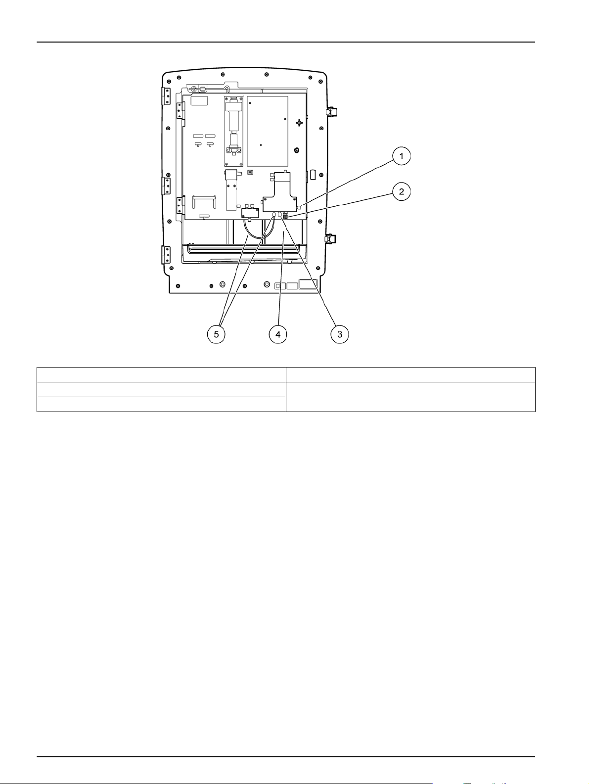
Figure 19 Modification of PHOSPHAX sc
1 Overflow vessel 4 Valve block
2 Fitting of sample tube 5 Sample tube
3 Blind plug
6.4 Shut the analyzer down
No special measures are necessary for taking out of operation for a
short period (up to a few days in frost-free ambient conditions).
Important note: If the power supply to the controller is interrupted,
frost damage may occur. Ensure that the instrument and tubing
cannot freeze.
1. Interrupt the measurement and switch the instrument to the
service state.
2. Isolate the analysis instrument from the controller.
6.4.1 Shut the analyzer down for an extended period
Important note: Always wear safety equipment when handling
chemicals.
Use the following procedure if the instrument is to be taken out of
operation for an extended period, or in the case of risk of frost.
1. Immerse the tubing for reagent and cleaning solutions in
distilled water.
45
Page 46

Maintenance
6.5 Scheduled maintenance
2. On the controller TEST/MAINT menu, start a cleaning cycle
with distilled water using the FLUSHING.
3. Clean the canister lid with distilled water.
4. Take the tubing out of the water and start the FLUSHING
function to pump the tubing and the analysis instrument empty.
5. Wipe the canister lids dry and seal the canisters with the
corresponding lids.
6. Remove the canisters and store them in a frost-free place and
in accordance with local regulations.
7. Isolate the system from the mains and the data network.
8. When using a Filter Probe sc, refer to the Filter Probe sc User
Manual for storage information.
9. Install all transport locks.
10. Depending on the duration, remove the system from its
mounting and wrap the system in a protective film or dry cloth.
Store the system in a dry place.
Table 5 lists items that need to be maintained by service personnel
ONLY. Contact the manufacturer for more information.
Table 5 Repair maintenance items
Description When to replace Warranty
Reagent pump for sc analyzer (Valve pumps) According to wear 1 year
Pump head piston pump 10 mL
(Pre-greased cylinder and piston)
Switchable Compressor 115/230V 2 years recommended 2 years
1 year 1 year
6.6 Modify from single channel to dual channel
The sc analyzer can be converted from single channel to dual
channel operation and/or continuous sampling. Contact the
manufacturer for more information. Refer to Table 6 for
configuration options.
Table 6 Conversions
From To With Conversion kit
1-channel operation 2-channel operation AMTAX sc, PHOSPHAX sc LZY170
Filter Probe sc Continuous sampling AMTAX sc, PHOSPHAX sc LZY241
Continuous sampling Filter Probe sc AMTAX sc, PHOSPHAX sc LZY242
46
Page 47

Section 7 Troubleshooting
7.1 Troubleshooting the controller
If entries are only implemented with a delay or are not accepted for
a short time, the delay may be caused by a busy data network.
Refer to the troubleshooting section in the sc1000 User Manual.
If, in normal operation, problems occur that are apparently caused
by the controller, restart the system.
After a software update, a system expansion or after an interruption
in the power supply, it may be necessary to set the system
parameters again.
Note all the values that are changed or entered so all the necessary
data can be used to configure the parameters again.
1. Save all important data.
2. Isolate the supply of power and wait for 5 seconds.
3. Reapply power to the controller.
4. Check all relevant settings.
5. If the problems still occurs, contact Technical Support.
7.2 Troubleshooting the analyzer
If the complete analysis instrument is not working, check whether
the humidity sensor has tripped. Fix the damage, dry the humidity
sensor and restart the system.
If the problems still occurs, contact Technical Support.
7.2.1 LED status
Table 7 LED Status and definitions
LED status Definition
green LED No errors of warnings
red LED Error
orange LED Warning
LED flashing No communication with controller
7.2.2 Error messages
Error displayed
TEMP.
< 0 °C/32°F?
ANALYZ. TOO
COLD
Instrument
reaction
Warms up and
goes into the
service state
Instrument goes
into the service
state
Cause Solution Reset error
instrument was
below 4 °C (39 °F)
on power up
Instrument interior
has been below
4 °C (39 °F) for
more than
5 minutes
Check whether instrument is frozen
(Cleaning solution/sample/reagent/
standards). If necessary use
pre-warmed reagents. Thaw electrode,
delete error. Instrument will then
continue to warm up and start
Close instrument, check heating
Reset error
manually
TEST/MAINT>
RESET ERROR
Reset error
manually
TEST/MAINT>
RESET ERROR
47
Page 48

Troubleshooting
7.2.2 Error messages (continued)
Error displayed
NO HEAT UP
COOLING FAILED
HUMIDITY ANALY Service state
HUMIDITY
PROBE
PROBE MISSING
TEMPSENS
DEFECT
CUVSENSOR
DEFECT
CUVHEAT
DEFECT
CUV TOO HOT
PHOTO LEVEL
LOW / PHOTO
LEVEL2 LOW
Instrument
reaction
Instrument goes
into the service
state
Service state,
starts
automatically after
cooling down
Service state, the
filtration probe sc
is isolated from the
mains
Service state, the
filtration probe sc
is isolated from the
mains
Service state, fan
running, heating off
Service state,
cuvette heating off
Continued
measurement
Service state,
cuvette heating off!
Continued
measurement
Cause Solution Reset error
Instrument cannot
heat interior
adequately.
(internal temp
<20°C (68°F) for
30 min)
Instrument interior
is too warm (>57°C
(135°F))
There is liquid in
the collecting tray
There is liquid in
the filtration probe
enclosure
The filtration probe
sc is faulty or not
connected
The temperature
sensor for the
internal instrument
temperature is
faulty
The temperature
sensor for the
cuvette is faulty
The cuvette is not
being heated
adequately
The cuvette is
over-heated.
Photometer signal
too low (1channel,
2 channel
operation ,
depending on
channel that
triggered the
error). Not enough
sample available.
Close instrument, check heating
Check air filter and clean/replace, check
fan.
Identify cause and rectify
Immediately take filtration probe sc out
of operation and contact service. Take
the filtration probe sc out of the tank and
store the filter modules so that they
remain moist. (See operating
instructions for the filtration probe sc).
Immediately take filtration probe sc out
of operation and contact service. Take
the filtration probe sc out of the tank and
store the filter modules so that they
remain moist. (See operating
instructions for the filtration probe sc).
Immediately switch off instrument,
contact service, replace main circuit
board
Contact service, replace cuvette/sensor
Close instrument door, contact service,
check cuvette heating, check main
circuit board
Sample too hot/ heating regulation
faulty, check main circuit board, contact
service
Trigger cleaning (several times).
Manually clean photometer. If this action
solves the problem, increase automatic
cleaning, otherwise contact service.
Check sample delivery.
Reset error
manually
Manual reset or
automatically when
temperature falls
2 °C (3.6 °F) below
limit
Reset error
manually
Reset error
manually
Reset error
manually
Reset error
manually
Reset error
manually
Reset error
manually
Reset error
manually
Reset error
manually or
automatic if level is
OK again
48
Page 49

7.2.2 Error messages (continued)
Troubleshooting
Error displayed
PHOTO LEVEL
HIGH / PHOTO
LEVEL2 HIGH
MODULES
CONTAM.
DRAIN BLOCKED Service state Drain is blocked Clean drain line
SAMPLE1 /
SAMPLE2
Instrument
reaction
Continued
measurement
Continued
measurement
Continued
measurement
Cause Solution Reset error
Photometer signal
too high (1
channel, 2 channel
operation ,
depending on
channel that
triggered the error)
Filter modules
heavily soiled
the amount of
sample is not
sufficient
(channel1 /
channel2) This
occurs as error if
SAMPLE
DETECTION is set
to ERROR
Contact service
Clean filter modules immediately
Check sample delivery, make sure that
sample line has no negative pressure,
check tightness of piston pump, check
overflow and air valve
7.2.3 Warnings
Reset error
manually or
automatic if level is
OK again
Reset error
manually
Reset error
manually
Automatic reset
when enough
sample is
available, or
manuell reset
Warning displayed
WARMUP PHASE
COOLING DOWN
ANALYZER TO COLD Measurement
ANALYZER TO WARM
CUV TOO COOL
Instrument
reaction
Instrument is
warming up sample
tubing after start
(de-frosting)
Fan 100 % ,
standstill until cool
enough
Measurement, but
no more air
cleaning
Continued
measurement
Cause Solution Reset warning
As far as possible, wait until
end of the warm-up phase
If there is a risk that the
sample tubing is frozen, a
warning is displayed
Instrument is cooling down
after start using ventilation,
if it was heated
excessively
Instrument has cooled
below 15°C (59 °F)
At very high internal
temperature, the air
cleaning of the filter
modules is disabled to
generate less wasteheat of
the internal compressor.
(internal temp. =
55°C(131°F ))
The cuvette is not being
heated adequately. 2 min
after sample change:
temp. = ((target temp. of
cuvette) - 1 °C(34°F))
(except if certain there is no
frost), to cancel please
place instrument in service
state and start
measurement again
Wait until instrument has
cooled down enough
Close instrument door, if
necessary check heating
Change/clean air filter,
check air ducts for blockage,
check enclosure fan, is
ambient temperature
allowed?
Close instrument door,
check/fit cuvette insulation.
Automatic
Reset,
automatically as
soon as cool
Reset,
automatically as
soon as warmer
Reset,
automatically as
soon as cool
Automatic
49
Page 50

Troubleshooting
7.2.3 Warnings (continued)
Warning displayed
PHOT LEVEL LOW /
PHOT LEVEL2 LOW
MODULES CONTAM.
SERVICE MODE Service state
REAGENT LEVEL
CLEAN SOLU LEVEL
Instrument
reaction
Continued
measurement
Continued
measurement
Continued
measurement
Continued
measurement
Cause Solution Reset warning
Trigger cleaning (several
times). Manually clean
Photometer signal low
(dependent on chanel if 2
chanel mode is used) .
Not enough sample.
Filter modules soiled Clean filter modules soon Automatic
The instrument is in the
service state or is
switching to this state
Amount of reagent has
dropped below warning
level set
Amount of cleaning
solution has dropped
below warning level set
photometer. If this action
solves the problem,
increase automatic
cleaning, otherwise contact
service. Check sample
delivery.
–
Check reagent level and
replace if necessary, then
reset reagent level. The
level is indicated
mathematically and can only
function reliably if the
counter is only reset when
the solution is changed
Check cleaning solution
level and replace if
necessary, then reset
cleaning solution level.
The level is indicated
mathematically and can only
function reliably if the
counter is only reset when
the solution is changed
Automatic
Automatic when
the service state
is left
On the menu
MAINTENANCE/
TEST/MAINT
COUNTER/
REAGENT
On the menu
MAINTENANCE/
TEST/MAINT
COUNTER/
CLEANING
SOLU.
50
Page 51

Section 8 Replacement Parts and Accessories
8.1 Standards and reagents
Description
Cleaning solution, PHOSPHAX sc (1 L) for all measurement ranges LCW870 28253-52
Reagent, PHOSPHAX sc (2 L) for all measurement ranges LCW869 28252-54
Cat. No.
EU customer
Cat. No.
US customer
8.2 Analyzer accessories
Description Cat. No.
Set of plugs , (rubber) for sc analyzer (type 1 (3), type 2 (1), type 3 (3)) LZY007
Accessories for AMTAX/PHOSPHAX sc for continuous sampling (1 or 2-channel) LZY189
Cutter for tubing LZY201
Heated drain hose, 230 V LZY302
Heated drain hose, 115 V LZY303
Set of connectors for sc analyzers LZY190
Set of screws for sc analyzer, M3x6 (4), M3x25 (2), M3x50 (2) LZY191
8.3 Mounting hardware
Description Cat. No.
Wall mount kit, includes 4 screws 5*60 incl. 4 anchors LZX355
Mounting kit for sc analyzer, includes fastening, angle bracket, and screws LZY044
Set of screws for fastening and angle bracket LZY216
Set of screws for sc analyzer LZY223
Set of screws for rail mounting LZY285 and LZY316 LZY220
Rail mounting, analyzer with controller LZY285
Rail mounting, analyzer without controller LZY316
Stand mounting, sc analyzer with controller LZY286
Stand mounting, sc analyzer without controller LZY287
8.4 Replacement parts
(Refer to Figure 20 on page 54–Figure 24 on page 58)
Item Description 1 Cat. No.
1 Door for sc analyzer enclosure LZY143
1 Door for sc analyzer enclosure (indoor) LZY682
1 Instrument labels (4 pieces) LZY144
2 Door hook LZY148
3 Enclosure for sc analyzer, without door on request
4 Set of filter pads (2 pieces) LZY154
5 Clamping lock for sc analyzer LZY147
6 Fence, includes screws M3 x 6 LZY157
7 Compressor switchable 115 V/230 V LZY149
8 Air tubing for compressor, includes non-return valve, fitting LZY151
9 Fan for incoming air LZY152
51
Page 52

Replacement Parts and Accessories
8.4 Replacement parts (continued)
(Refer to Figure 20 on page 54–Figure 24 on page 58)
Item Description 1 Cat. No.
10 Collecting tray, for sc analyzer LZY146
11 Hinge, includes screws LZY155
12 Gasket for door of sc analyzer LZY187
13 Door lock sc analyzer LZY188
14 Mounting plate for sc analyzer LZY161
15 Analyzer panel of PHOSPHAX sc, measurement range: 0.05–15 mg/L on request
16 Analyzer panel of PHOSPHAX sc, measurement range: 1–50 mg/L on request
17 Measuring cell, PHOSPHAX sc, measurement range: 0.05–15 mg/L LZY185
18 Measuring cell, PHOSPHAX sc, measurement range: 1–50 mg/L LZY186
19 Valve block, PHOSPHAX sc, includes valves; measurement range: 0.05–15 mg/L LZY183
20 Valve block, PHOSPHAX sc, includes valves; measurement range:: 1–50 mg/L LZY160
21 Valve block, PHOSPHAX sc, measurement range: 0.05–15 mg/L LZY271
22 Valve block, PHOSPHAX sc, measurement range:: 1–50 mg/L LZY272
23 Upper part of valve block LZY174
24 Upper part of valve block with valve LZY175
25 Valve 2/2 ways LZY168
26 Tubing 3.2 mm (2 m), sc analyzer LZY195
27 Set of fittings 3.2 mm, (4 pieces) LZ Y111
28 Fitting for tubing DN4/6 LZY134
29 Blind plug LZY193
30 Valve block 2-channel switch, includes valve for sc analyzer LZY267
31 Valve block 2-channel switch for sc analyzer LZY172
32 Valve 3/2 ways LZY171
33 Conversion kit from 1-channel > Filter Probe sc analyzer, AMTAX sc/PHOSPHAX sc LZY242
34 Bottom part of overflow vessel LZY165
35 Upper part of overflow vessel LZY166
36 Upper part of overflow vessel includes valve LZY167
37 Locking screw LZY150
38 Conversion kit from Filter Probe sc > 1-channel sc analyzer, AMTAX sc/PHOSPHAX sc LZY241
39 Upper part of overflow vessel for 1 or 2-channel instrument LZY268
40 Overflow vessel for 2-channel instrument LZY269
41 Safety plate for sc analyzer LZY179
42 Insulation cover for photometer, PHOSPHAX sc measurement range: 0.05–15 mg/L LZY225
43 Insulation cover for photometer, PHOSPHAX sc measurement range: 1–50 mg/L LZY226
44 Holder for piston pump LZY180
45 Pump head for air pump, 10 mL LZY181
46 Piston pump for sc analyzer LZY177
47 Cover for reagent pump LZY178
48 Set of fittings, 1.6 mm, (4 pieces) LZY192
49 Tubing, 1.6 mm (2 m), sc analyzer LZY194
50 Reagent pump, for sc analyzer (valve pump) LZY176
51 Fan for air recirculation for sc analyzer LZY153
52
Page 53

Replacement Parts and Accessories
8.4 Replacement parts (continued)
(Refer to Figure 20 on page 54–Figure 24 on page 58)
Item Description 1 Cat. No.
52 Heating for analyzer enclosure, includes connectors LZY156
53 Cover LZY270
54 Cover for processor card LZY159
55 Cover for power supply LZY158
56 Power supply, 100-240 VAC YAB039
57 Amplifier card for PHOSPHAX sc YAB045
58 Processor card for sc analyzer YAB099
59 Set of seals for PHOSPHAX sc measuring cell (4 O-rings) LZY197
60 Sealing for valve block LZY199
61 Sealing for overflow vessel LZY198
62 Card with temperature sensor, AMTAX sc/PHOSPHAX sc YAB089
63 Air filter LZY493
64 Check valve LZY470
65 T-fitting LZY133
17+19+42 Conversion kit PHOSPHAX sc from HR to LR LZY313
18+20+43 Conversion kit PHOSPHAX sc from LR to HR LZY312
30+40 Conversion kit from 1-channel into 2-channel sc analyzer LZY170
53
Page 54

Replacement Parts and Accessories
Exploded view drawings
54
Figure 20 Analyzer enclosure PHOSPHAX sc
Page 55

Replacement Parts and Accessories
1 2
3
4
5
6
7
8
9
10
11
12
13
5
60
Figure 21 Analyzer enclosure PHOSPHAX indoor sc
55
Page 56

Replacement Parts and Accessories
56
Figure 22 Analyzer panel overview
Page 57

Replacement Parts and Accessories
Figure 23 Analyzer panel front view details
57
Page 58

Replacement Parts and Accessories
58
Figure 24 Analyzer panel back view details
Page 59

Section 9 Contact Information
HACH Company
World Headquarters
P.O. Box 389
Loveland, Colorado
80539-0389 U.S.A.
Tel (800) 227-HACH
(800) -227-4224
(U.S.A. only)
Fax (970) 669-2932
orders@hach.com
www.hach.com
HACH LANGE GMBH
Willstätterstraße 11
D-40549 Düsseldorf
Tel. +49 (0)2 11 52 88-320
Fax +49 (0)2 11 52 88-210
info@hach-lange.de
www.hach-lange.de
HACH LANGE GMBH
Rorschacherstrasse 30a
CH-9424 Rheineck
Tel. +41 (0)848 55 66 99
Fax +41 (0)71 886 91 66
info@hach-lange.ch
www.hach-lange.ch
Repair Service in the
United States:
HACH Company
Ames Service
100 Dayton Avenue
Ames, Iowa 50010
Tel (800) 227-4224
(U.S.A. only)
Fax (515) 232-3835
HACH LANGE LTD
Pacific Way
Salford
GB-Manchester, M50 1DL
Tel. +44 (0)161 872 14 87
Fax +44 (0)161 848 73 24
info@hach-lange.co.uk
www.hach-lange.co.uk
HACH LANGE FRANCE
S.A.S.
8, mail Barthélémy Thimonnier
Lognes
F-77437 Marne-La-Vallée
cedex 2
Tél. +33 (0) 820 20 14 14
Fax +33 (0)1 69 67 34 99
info@hach-lange.fr
www.hach-lange.fr
Repair Service in Canada:
Hach Sales & Service
Canada Ltd.
1313 Border Street, Unit 34
Winnipeg, Manitoba
R3H 0X4
Tel (800) 665-7635
(Canada only)
Tel (204) 632-5598
Fax (204) 694-5134
canada@hach.com
HACH LANGE LTD
Unit 1, Chestnut Road
Western Industrial Estate
IRL-Dublin 12
Tel. +353(0)1 460 2522
Fax +353(0)1 450 9337
info@hach-lange.ie
www.hach-lange.ie
HACH LANGE NV/SA
Motstraat 54
B-2800 Mechelen
Tel. +32 (0)15 42 35 00
Fax +32 (0)15 41 61 20
info@hach-lange.be
www.hach-lange.be
Repair Service in
Latin America, the
Caribbean, the Far East,
Indian Subcontinent, Africa,
Europe, or the Middle East:
Hach Company World
Headquarters,
P.O. Box 389
Loveland, Colorado,
80539-0389 U.S.A.
Tel +001 (970) 669-3050
Fax +001 (970) 669-2932
intl@hach.com
HACH LANGE GMBH
Hütteldorfer Str. 299/Top 6
A-1140 Wien
Tel. +43 (0)1 912 16 92
Fax +43 (0)1 912 16 92-99
info@hach-lange.at
www.hach-lange.at
DR. LANGE NEDERLAND
B.V.
Laan van Westroijen 2a
NL-4003 AZ Tiel
Tel. +31(0)344 63 11 30
Fax +31(0)344 63 11 50
info@hach-lange.nl
www.hach-lange.nl
HACH LANGE APS
Åkandevej 21
DK-2700 Brønshøj
Tel. +45 36 77 29 11
Fax +45 36 77 49 11
info@hach-lange.dk
www.hach-lange.dk
HACH LANGE LDA
Av. do Forte nº8
Fracção M
P-2790-072 Carnaxide
Tel. +351 214 253 420
Fax +351 214 253 429
info@hach-lange.pt
www.hach-lange.pt
HACH LANGE KFT.
Vöröskereszt utca. 8-10.
H-1222 Budapest XXII. ker.
Tel. +36 1 225 7783
Fax +36 1 225 7784
info@hach-lange.hu
www.hach-lange.hu
HACH LANGE AB
Vinthundsvägen 159A
SE-128 62 Sköndal
Tel. +46 (0)8 7 98 05 00
Fax +46 (0)8 7 98 05 30
info@hach-lange.se
www.hach-lange.se
HACH LANGE SP. ZO.O.
ul. Krakowska 119
PL-50-428 Wrocław
Tel. +48 801 022 442
Fax +48 717 174 088
info@hach-lange.pl
www.hach-lange.pl
HACH LANGE S.R.L.
Str. Căminului nr. 3,
et. 1, ap. 1, Sector 2
RO-021741 Bucureşti
Tel. +40 (0) 21 205 30 03
Fax +40 (0) 21 205 30 17
info@hach-lange.ro
www.hach-lange.ro
HACH LANGE S.R.L.
Via Riccione, 14
I-20156 Milano
Tel. +39 02 39 23 14-1
Fax +39 02 39 23 14-39
info@hach-lange.it
www.hach-lange.it
HACH LANGE S.R.O.
Zastrčená 1278/8
CZ-141 00 Praha 4 - Chodov
Tel. +420 272 12 45 45
Fax +420 272 12 45 46
info@hach-lange.cz
www.hach-lange.cz
HACH LANGE
8, Kr. Sarafov str.
BG-1164 Sofia
Tel. +359 (0)2 963 44 54
Fax +359 (0)2 866 15 26
info@hach-lange.bg
www.hach-lange.bg
HACH LANGE S.L.U.
Edif. Arteaga Centrum
C/Larrauri, 1C- 2ª Pl.
E-48160 Derio/Vizcaya
Tel. +34 94 657 33 88
Fax +34 94 657 33 97
info@hach-lange.es
www.hach-lange.es
HACH LANGE S.R.O.
Roľnícka 21
SK-831 07 Bratislava –
Vaj nory
Tel. +421 (0)2 4820 9091
Fax +421 (0)2 4820 9093
info@hach-lange.sk
www.hach-lange.sk
HACH LANGE SU
ANALİZ SİSTEMLERİ
LTD.ŞTİ.
Ilkbahar mah. Galip Erdem
Cad. 616 Sok. No:9
TR-Oran-Çankaya/ANKARA
Tel. +90312 4908300 Ext. 140
Fax +90312 4919903
bilgi@hach-lange.com.tr
www.hach-lange.com.tr
59
Page 60

Contact Information
HACH LANGE D.O.O.
Fajfarjeva 15
SI-1230 Domžale
Tel. +386 (0)59 051 000
Fax +386 (0)59 051 010
info@hach-lange.si
www.hach-lange.si
ΗΑCH LANGE E.Π.Ε.
Αυλίδος 27
GR-115 27 Αθήνα
Τηλ . +30 210 7777038
Fax +30 210 7777976
info@hach-lange.gr
www.hach-lange.gr
HACH LANGE D.O.O.
Ivana Severa bb
HR-42 000 Varaždin
Tel. +385 (0) 42 305 086
Fax +385 (0) 42 305 087
info@hach-lange.hr
www.hach-lange.hr
HACH LANGE MAROC
SARLAU
Villa 14 – Rue 2 Casa
Plaisance
Quartier Racine Extension
MA-Casablanca 20000
Tél. +212 (0)522 97 95 75
Fax +212 (0)522 36 89 34
info-maroc@hach-lange.com
www.hach-lange.ma
60
Page 61

Section 10 Limited Warranty
The manufacturer warrants that the product supplied is free of
material and manufacturing defects and undertakes the obligation
to repair or replace any defective parts at zero cost.
The warranty period for instruments is 24 months. If a service
contract is taken out within 6 months of purchase, the warranty
period is extended to 60 months.
With the exclusion of the further claims, the supplier is liable for
defects including the lack of assured properties as follows: all those
parts that, within the warranty period calculated from the day of the
transfer of risk, can be demonstrated to have become unusable or
that can only be used with significant limitations due to a situation
present prior to the transfer of risk, in particular due to incorrect
design, poor materials or inadequate finish will be improved or
replaced, at the supplier's discretion. The identification of such
defects must be notified to the supplier in writing without delay,
however at the latest 7 days after the identification of the fault. If the
customer fails to notify the supplier, the product is considered
approved despite the defect. Further liability for any direct or
indirect damages is not accepted.
If instrument-specific maintenance and servicing work defined by
the supplier is to be performed within the warranty period by the
customer (maintenance) or by the supplier (servicing) and these
requirements are not met, claims for damages due to the failure to
comply with the requirements are rendered void.
Any further claims, in particular claims for consequential damages
cannot be made.
Consumables and damage caused by improper handling, poor
installation or incorrect use are excluded from this clause.
The manufacturer process instruments are of proven reliability in
many applications and are therefore often used in automatic control
loops to provide the most economical possible operation of the
related process.
To avoid or limit consequential damage, it is therefore
recommended to design the control loop such that a malfunction in
an instrument results in an automatic change over to the backup
control system; this is the safest operating state for the environment
and the process.
61
Page 62

Limited Warranty
62
Page 63

Section 11 Certification
Product Safety
Immunity
The manufacturer certifies this instrument was tested thoroughly,
inspected and found to meet its published specifications when it
was shipped from the factory.
The Model AMTAX sc, PHOSPHAX sc, and Filter Probe sc used
with the Model sc1000 Controller have been tested and is certified
as indicated to the following instrumentation standards:
UL 61010A-1 (cTUVus Certificate No. CU 72053093 01)
CSA C22.2 No. 1010.1 (cTUVus Certificate No. CU 72053093 01)
EN 61010-1: 2001 per 2006/95/EC (TUV-GS. Certificate No. S
72053093)
This equipment was tested for Industrial level EMC per:
EN 61326: A1 & A2 (EMC Requirements for Electrical Equipment
for Measurement, Control and Laboratory Use)
Supporting test records by Hach Company, certified
EMC:
compliance by Hach Company.
per 89/336/EEC
Emissions
Standards include:
IEC 1000-4-2:1995 (EN 61000-4-2:1995) Electro-Static Discharge
Immunity (Criteria B)
IEC 1000-4-3:1995 (EN 61000-4-3:1996) Radiated RF
Electro-Magnetic Field Immunity (Criteria A)
IEC 1000-4-4:1995 (EN 61000-4-4:1995) Electrical Fast
Transients/Burst (Criteria B)
IEC 1000-4-5:1995 (EN 61000-4-5:1995) Surge (Criteria B)
IEC 1000-4-6:1996 (EN 61000-4-6:1996) Conducted Disturbances
Induced by RF Fields (Criteria A)
IEC 1000-4-11:1994 (EN 61000-4-11:1994) Voltage Dip/Short
Interruptions (Criteria B)
This equipment was tested for Radio Frequency Emissions as
follows:
Per 89/336/EEC EMC: EN 61326: A1 & A2 (Electrical Equipment
for measurement, control and laboratory use-EMC requirements)
Class “A” emission limits. Supporting test records by WE-EM
Nachrichtentechnik GmbH German Test Center and certified
compliance by Hach Company.
Standards include:
EN 61000-3-2 Harmonic Disturbances Caused by Electrical
Equipment
EN 61000-3-3 Voltage Fluctuation (Flicker) Disturbances Caused
by Electrical Equipment
Additional Emissions Standard/s include:
EN 55011 (CISPR 11), Class “A” emission limits
63
Page 64

Certification
64
Page 65

Appendix A Plumbing and connection options
A.1 Safety information
When making any plumbing or wiring connections, the following
warnings must be adhered to, as well as any warnings and notes
found throughout the individual sections. For more safety
information, refer to Safety information, page 9.
DANGER
Always disconnect power to the instrument when making any
electrical connections.
CAUTION
The enclosure may tip forwards if it has not been fixed in
place. Only open the enclosure if the enclosure is properly
mounted to prevent tipping.
A.1.1 Electrostatic Discharge (ESD) Considerations
Important Note: To minimize hazards an d ESD risks, maintenance
procedures not requiring power to the analyzer should be
performed with power removed.
Delicate internal electronic components can be damaged by static
electricity, resulting in degraded instrument performance or
eventual failure.
The manufacturer recommends taking the following steps to
prevent ESD damage to the instrument:
• Before touching any instrument electronic components (such
as printed circuit cards and the components on them)
discharge static electricity. This can be accomplished by
touching an earth-grounded metal surface such as the chassis
of an instrument, or a metal conduit or pipe.
• To reduce static build-up, avoid excessive movement.
Transport static-sensitive components in anti-static containers
or packaging.
• To discharge static electricity and keep it discharged, wear a
wrist strap connected by a wire to earth ground.
• Handle all static-sensitive components in a static-safe area. If
possible, use anti-static floor pads and work bench pads.
65
Page 66

Plumbing and connection options
A.2 Connect a 2-parameter option
The 2-parameter configuration is required for Options 4, 6, 8b, 9b,
10b, and 11b.
When using a continuous sample the PHOSPHAX sc can measure
one parameter: PO
3–
. To operate a second parameter with the
4
same continuous sample (i.e. ammonium measured by the
AMTAX sc) the sample line must be connected to the overflow
vessel of the first instrument in the row. For this purpose, the first
instrument must be modified to the 2-parameter variant.
Note: The 2-parameter configuration applies to outdoor and indoor options
and to one and two-channel options (Ch1 + Ch2).
Refer to Figure 25 and following instructions to connect a
2-parameter configuration.
1. Remove the small blind plug (item 1, Figure 25) from the top
hole on the overflow vessel. Remove the large fitting (item 2)
from the bottom hole on the overflow vessel. Discard the plug
and fitting.
2. Slide the small fitting (union and ferrule, item 3) over the tubing
(item 5). Cut the tubing flush with the ferrule.
3. Install the small fitting to the top hole on the overflow vessel to
take the sample to the second analyzer.
4. Close the bottom hole with the large blind plug and sealing
washer (item 4).
Note: Always connect the front overflow vessel for the first instrument
to the front overflow vessel for the second instrument.
Figure 25 Modify the first instrument to a 2-parameter option
1 Small plug 4 Large plug LZY193
2 Large fitting 5 Tubing LZY195
3 Small fitting and ferrule LZY111 6 To second analyzer
66
Page 67

A.2.1 Remove the T-fitting
Plumbing and connection options
When using the 2-parameter configuration, the T-fitting from the
first analyzer drain tube must be removed and reused to connect
the drain tube from the first analyzer to the second analyzer.
The T-fitting is used to connect the drain tube. To remove the
T-fitting refer to Figure 26 and the following steps:
1. Remove the drain tube from both ends of the T-fitting.
2. Remove the drain tube assembly.
3. Reconnect the T-fitting as described in Options 4, 6, 8b, 9b,
10b, and 11b.
Figure 26 Removing the T-fitting
1 T-fitting to be removed
A.3 Drain line considerations
A.4 Tubing considerations
Always place the drain tubing so that there is a continuous fall
(minimum 3°) and the outlet is clear (not pressurized). Make sure
the drain tubing is no longer than 2 meters.
The analyzer uses four different tubing types for plumbing
connections. The type of tubing used depends on the instrument
configuration:
• Ø 3
• Ø 6 mm: unheated drain tubing
• Ø 22 mm: heated drain tubing
• Ø 32 mm: tubing for the Filter Probe sc
.,2 mm: sample line tubing
67
Page 68

Plumbing and connection options
A.5 Option 1 plumbing and connections
Option 1 is used with an sc analyzer and the Filter Probe sc. The
waste from the analyzer is discharged back into the basin using the
Filtration Kit. Use the drain tube inside the Filter Probe sc or the
optional heated drain tube to discharge the waste stream from the
sc analyzer.
Refer to Figure 27 and the following instructions for Option 1:
1. Install the Filter Probe sc into the sample stream. Refer to the
Filter Probe sc User Manual for more information.
2. Feed the Filter Probe sc hose (sample lines, electrical cables
and drain tube) through the analyzer opening (Figure 27,
item 5). Use Seal Plug #2 to secure.
3. Seal the unused openings with Seal Plug #3.
4. Connect the Filter Probe sc data cable and power connections.
Refer to section 3.5.4, page 26.
5. Connect the air tube to the compressor (item 3).
6. Connect the drain tube to the Filter Probe sc.
7. Connect the sample line to the sample inlet on the overflow
vessel using the fittings.
68
Page 69

Plumbing and connection options
Figure 27 Option 1 setup
1 PHOSPHAX sc analyzer 5 Filter Probe sc hose
2 AMTAX sc analyzer 6 Seal plug #2
3 Air tube 7 Sample line to overflow vessel
4 Seal plug #3 8 Drain tube
69
Page 70

Plumbing and connection options
A.6 Option 2 plumbing and connections
Option 2 uses an sc analyzer with the Filter Probe sc. The waste
from the analyzer is discharged back into the drain through the
optional heated drain hose LZY302 (230 V) or LZY303 (115 V).
Refer to Figure 28 and the following instructions for Option 2:
1. Install the Filter Probe sc into the sample stream. Refer to the
Filter Probe sc User Manual for more information.
2. Feed the Filter Probe sc hose (sample lines, electrical cables,
drain tube) through the analyzer opening (Figure 28, item 9).
Use Seal Plug #2 to secure.
Note: The drain tube from the Filter Probe sc is not used .
3. Feed the heated drain hose through the analyzer opening
(item 7). Use Seal Plug #1 to secure.
Note: The two samples lines of the heated drain hose are not used.
4. Seal the remaining opening with Seal Plug #3.
5. Connect the Filter Probe sc data cable and power connections.
Refer to section 3.5.4, page 26.
6. Connect the heated drain power connections. Refer to
section 3.5.5, page 27.
7. Connect the air tube to the compressor (item 5).
8. Connect the Filter Probe sc heated drain tube to the sample
outlet T-fitting.
9. Connect the sample line to the sample inlet on the overflow
vessel using the fittings.
70
Page 71

Plumbing and connection options
Figure 28 Option 2 setup
1 PHOSPHAX sc analyzer 7 Heated drain tube
2 AMTAX sc analyzer 8 Seal plug #1
3 Unused heated drain sample lines 9 Filter Probe sc hose
4 Unused Filter Probe sc drain tube 10 Seal plug #2
5 Air tube 11 Filter Probe sc sample line
6 Seal plug #3 12 Heated drain
71
Page 72

Plumbing and connection options
A.7 Option 3 plumbing and connections
Option 3 uses an sc analyzer with the FILTRAX. The waste from
the analyzer is discharged back into the drain through the optional
heated drain hose LZY302 (230V) or LZY303 (115V).
Refer to Figure 29 and the following instructions for Option 3:
1. Install the FILTRAX into the sample stream. Refer to the
FILTRAX User Manual for more information.
2. Feed the heated hose from the FILTRAX through the analyzer
opening (Figure 29, item 5). Use Seal Plug #1 to secure.
3. Feed the heated drain hose through the analyzer opening
(item 3). Use Seal Plug #1 to secure.
Note: The two samples lines of the heated drain hose are not used.
4. Seal the remaining opening with Seal Plug #3.
5. Connect the heated drain power connections. Refer to
section 3.5.5, page 27.
6. Connect the heated drain tube to the sample outlet T-fitting.
72
Page 73

Plumbing and connection options
Figure 29 Option 3 setup
1 Unused heated drain sample lines 5 FILTRAX heated hose
2 Seal plug #3 6 Seal plug #1
3 Heated drain hose 7 FILTRAX sample line
4 Seal plug #1 8 Heated drain tube
73
Page 74

Plumbing and connection options
A.8 Option 4 plumbing and connections
Option 4 uses two sc analyzers with the FILTRAX. The sample from
the FILTRAX goes to the first analyzer which needs to change to a
2-parameter configuration (see Connect a 2-parameter option,
page 66). The heated drain hose connects both sc analyzers.The
waste from both analyzers is discharged back into a drain through
the second heated drain hose.
Refer to Figure 30 and the following instructions for Option 4:
1. Install the FILTRAX into the sample stream. Refer to the
FILTRAX User Manual for more information.
2. Install the first sc analyzer (Analyzer 1):
a. Feed the heated hose from the FILTRAX through the
analyzer opening (Figure 30, item 15). Use Seal Plug #1
to secure.
b. Feed the heated drain hose though the analyzer opening
(item 17). Use Seal Plug #1 to secure.
c. Seal the remaining opening with Seal Plug #3.
d. Connect the heated drain power connections. Refer to
section 3.5.5, page 27.
e. Remove the pre-installed drain tube attached to the valve
block and remove the T-fitting from the drain tube (item 7).
Retain for reuse with Analyzer 2.
f. Connect the heated drain tube to the valve block connector.
g. Connect the sample line from the FILTRAX to the bottom
inlet on the overflow vessel using the fittings.
h. Change the analyzer to the 2 parameter configuration.
Refer to Connect a 2-parameter option, page 66.
i. Connect one of the sample lines from the heated drain to
the overflow vessel.
74
Page 75

Plumbing and connection options
3. Install the second sc analyzer (Analyzer 2):
a. Feed the heated drain hose from Analyzer 1 through
Analyzer 2 (item 12). Use Seal Plug #1 to secure.
b. Feed the second heated drain hose through Analyzer 2
(item 11). Use Seal Plug #1 to secure.
c. Seal the remaining opening with Seal Plug #3.
d. Connect the heated drain power connections. Refer to
section 3.5.5, page 27.
e. Cut 25 mm from the drain tube that was removed from
Analyzer 1. Connect the 25 mm piece of tubing to the
T-fitting on Analyzer 2. Connect the other end of the tubing
to the T-fitting that was removed from Analyzer 1. Refer to
Figure 26, page 67 for T-fitting removal.
f. Connect the drain tube from Analyzer 1 and the drain tube
from Analyzer 2 to the T-fitting.
4. Connect the sample line from Analyzer 1 to the bottom inlet on
the overflow vessel.
75
Page 76

Plumbing and connection options
Figure 30 Option 4 setup
1 PHOSPHAX sc analyzer 8 Heated drain tube 15 FILTRAX heated hose
2 AMTAX sc analyzer 9 Heated drain tube from analyzer 1 16 Seal plug #1
3 Seal plug #1 10 Sample line from analyzer 1 17 Heated drain hose
4 Seal plug #3 11 Heated drain hose 18 Seal plug #3
5 Unused heated drain sample lines 12 Heated drain hose from analyzer 1 19 Unused heated drain sample line
6 Drain tube cut from analyzer 1 13 Heated drain tube 20 Heated drain sample line
7 T-fitting from analyzer 1 14 FILTRAX sample line
76
Page 77

A.9 Option 5 plumbing and connections
Option 5 uses an sc analyzer as a 2-channel analyzer with two
FILTRAX (FILTRAX 1 and FILTRAX 2), supplying two continuous
sample streams. The waste from the analyzer and both FILTRAX is
discharged back into the drain through the optional heated drain
hose LZY302 (230 V) or LZY303 (115 V).
Refer to Figure 31 and the following instructions for Option 5:
1. Install both FILTRAX into the sample stream. Refer to the
FILTRAX User Manual for more information.
2. Feed the heated hose from FILTRAX 1 through the analyzer
opening (Figure 31, item 7). Use Seal Plug #1 to secure.
3. Feed the heated hose from FILTRAX 2 through the analyzer
opening (item 6). Use Seal Plug #1 to secure.
4. Feed the heated drain hose through the analyzer (item 5). Use
Seal Plug #1 to secure.
Note: The two samples lines of the heated drain hose are not used.
5. Connect the heated drain power connections. Refer to
section 3.5.5, page 27.
Plumbing and connection options
6. Connect the heated drain tube to the T-fitting (item 8).
7. Connect the sample line from FILTRAX 1 to the bottom inlet on
Overflow Vessel 1 using the fittings (item 11).
8. Connect the sample line from FILTRAX 2 to the bottom inlet on
Overflow Vessel 2 using the fittings (item 12).
77
Page 78

Plumbing and connection options
Figure 31 Option 5 setup
1 FILTRAX 1 7 FILTRAX heated hose 1
2 FILTRAX 2 8 Heated drain tube
3 Seal plug #1 9 FILTRAX 2 sample line
4 Unused heated drain sample lines 10 FILTRAX 1 sample line
5 Heated drain hose 11 Overflow vessel 1
6 FILTRAX heated hose 2 12 Overflow vessel 2
78
Page 79

A.10 Option 6 plumbing and connections
Option 6 uses two sc analyzers with two FILTRAX (FILTRAX 1 and
FILTRAX 2). Samples from both FILTRAX are going into Analyzer 1
using the 2-parameter configuration. The heated drain hose
connects both sc analyzers. The waste from both analyzers is
discharged into a drain through the heated drain hose.
Refer to Figure 32 and the following instructions for Option 6:
1. Install both FILTRAX into the sample stream. Refer to the
FILTRAX User Manual for more information.
2. Install the first sc analyzer (Analyzer 1):
a. Feed the heated hose from FILTRAX 1 through the
analyzer (Figure 32, item 25). Use Seal Plug #1 to secure.
b. Feed the heated hose from FILTRAX 2 through the
analyzer (item 27). Use Seal Plug #1 to secure.
c. Feed the heated drain hose through the analyzer (item 28).
Use Seal Plug #1 to secure. Connect the heated drain
power connections. Refer to section 3.5.5, page 27.
d. Remove the pre-installed drain tube attached to the valve
block and remove the T-fitting from the drain tube. Retain
for reuse with Analyzer 2.
Plumbing and connection options
e. Connect the heated drain tube to the valve block connector.
f. Connect the sample line from FILTRAX 1 to the bottom inlet
on Overflow Vessel 1 using the fittings (item 20).
g. Connect the sample line from FILTRAX 2 to the bottom inlet
on Overflow Vessel 2 using the fittings (item 19).
h. Change the analyzer to the 2-parameter configuration.
Refer to Connect a 2-parameter option, page 66.
i. Connect Sample Line 1 from the heated drain to Overflow
Vessel 1. Connect Sample Line 2 from the heated drain to
Overflow Vessel 2.
3. Install the second sc analyzer (Analyzer 2)
a. Feed the heated drain hose from Analyzer 1 through
Analyzer 2 (item 13). Use Seal Plug #1 to secure.
b. Feed the heated drain hose through the analyzer (item 8).
Use Seal Plug #1 to secure. Connect the heated drain
power connections. Refer to section 3.5.5, page 27.
c. Seal the remaining opening with Seal Plug #3.
d. Cut 25 mm from the drain tube that was removed from
Analyzer 1. Connect the 25 mm piece of tubing to the
T-fitting on Analyzer 2. Connect the other end of the tubing
to the T-fitting that was removed from Analyzer 1. Refer to
Figure 26, page 67 for T-fitting removal.
e. Connect the drain tube from Analyzer 1 and the drain tube
from Analyzer 2 to the T-fitting.
4. Connect Sample Line 1 from Analyzer 1 to Overflow Vessel 1
using the fittings (item 16). Connect Sample Line 2 from
Analyzer 1 to Overflow Vessel 2 using the fittings (item 17).
79
Page 80

Plumbing and connection options
Figure 32 Option 6 setup
1 FILTRAX 1 11 Heated drain tube 21 Overflow vessel 1
2 PHOSPHAX sc analyzer 12 Heated drain tube from analyzer 1 22 Overflow vessel 2
3 AMTAX sc analyzer 13 Heated drain tube from analyzer 1 23 Heated drain 1 sample line
4 FILTRAX 2 14 Heated drain sample 2 from analyzer 1 24 Heated drain 2 sample line
5 Seal plug #1 15 Heated drain sample 1 from analyzer 1 25 FILTRAX 1 heated hose
6 Seal plug #3 16 Overflow vessel 1 26 Seal plug #1
7 Unused heated drain sample lines 17 Overflow vessel 2 27 FILTRAX 2 heated hose
8 Heated drain hose 18 Heated drain tube 28 Heated drain hose
9 Drain tube cut from analyzer 1 19 FILTRAX 2 sample line
10 T-fitting from analyzer 1 20 FILTRAX 1 sample line
80
Page 81

A.11 Option 7 plumbing and connections
Option 7 is used with an sc analyzer and the Filter Probe sc. The
waste from the analyzer is discharged back into the basin using the
Filtration Kit. Use the drain tube inside the Filter Probe sc or the
optional heated drain tube to discharge the waste stream from the
sc analyzer.
Refer to Figure 33 and the following instructions for Option 7:
1. Install the Filter Probe sc into the sample stream. Refer to the
Filter Probe sc User Manual for more information.
2. Feed the Filter Probe sc hose (sample lines, electrical cables,
drain tube) through the analyzer opening (Figure 33, item 6).
Use Seal Plug #2 to secure.
3. Seal the unused openings with Seal Plug #3.
4. Connect the Filter Probe sc data cable and power connections.
Refer to section 3.5.4, page 26.
5. Connect the air tube to the compressor (item 4).
6. Connect the drain tube and feed it out the analyzer through
Seal Plug #3 to a drain.
Plumbing and connection options
7. Connect the sample line to the sample inlet on the overflow
vessel using the fittings (item 8).
81
Page 82

Plumbing and connection options
Figure 33 Option 7 setup
1 PHOSPHAX sc analyzer 6 Filter Probe sc hose
2 AMTAX sc analyzer 7 Seal plug #2
3 Unused Filter Probe sc drain tube 8 Sample line to overflow vessel
4 Air tube 9 Drain tube
5 Seal plug #3
82
Page 83

A.12 Option 8a plumbing and connections
Option 8a uses an sc analyzer with the FILTRAX. The waste of the
analyzer is discharged back into an open drain.
Refer to Figure 34 and the following instructions for Option 8a:
1. Install the FILTRAX into the sample stream. Refer to the
FILTRAX User Manual for more information.
2. Feed the heated hose from the FILTRAX through the analyzer
opening (Figure 34, item 3). Use Seal Plug #1 to secure.
3. Feed the drain tube through the analyzer opening (item 5).
Use Seal Plug #3 to secure.
Note: Tubes can be pushed through prepared holes on Seal Plug #3.
4. Connect the drain tube to the T-fitting.
5. Connect the FILTRAX sample line to the bottom inlet on the
overflow vessel using the fittings (item 4).
Plumbing and connection options
6. Feed the drain tube to a lower drain (maximum 2 m/6
.,5ft).
83
Page 84

Plumbing and connection options
Figure 34 Option 8a setup
1 Seal plug #3
2 Seal plug #1
3 FILTRAX heated hose
4 FILTRAX sample line
5 Drain tube: Feed to a lower drain (maximum 2 m/6.5 ft)
84
Page 85

A.13 Option 8b plumbing and connections
Option 8b uses two sc analyzers with the FILTRAX. The sample of
the FILTRAX goes to the first sc analyzer. This analyzer must use
the 2-parameter configuration (see A.2, page 66). Each sc analyzer
discharges waste into an open drain.
Refer to Figure 35 and the following instructions for Option 8b:
1. Install the FILTRAX into the sample stream. Refer to the
FILTRAX User Manual for more information.
2. Install the first sc analyzer (Analyzer 1):
a. Feed the heated hose from the FILTRAX through the
analyzer opening (Figure 35, item 8). Use Seal Plug #1
to secure.
b. Feed the drain tube through the analyzer opening (item 6)
and to an open drain below Analyzer 1. Use Seal Plug #3
to secure.
c. Change the analyzer to the 2-parameter configuration.
Refer to Connect a 2-parameter option, page 66.
d. Connect the reworked overflow of the overflow vessel to
deliver the sample to Analyzer 2.
Plumbing and connection options
e. Feed the overflow vessel tubing (item 11) through
Analyzer 1 to Analyzer 2. Use Seal Plug #3 to secure.
f. Remove the drain tube with the T-fitting from the valve
block connector. This drain tube is not used.
g. Connect the drain tube to the valve block connector
(item 6).
h. Connect the FILTRAX sample line to the bottom inlet on the
overflow vessel using the fittings (item 7).
3. Install the second sc analyzer (Analyzer 2):
a. Feed the sample line from Analyzer 1 through Analyzer 2
(item 4). Use Seal Plug #3 to secure.
b. Feed the drain tube through Analyzer 2 to an open drain
below. Use Seal Plug #3 to secure.
c. Use Seal Plug #3 to seal any unused openings.
d. Connect the drain tube to the T-fitting (item 5).
e. Connect the sample line from Analyzer 1 to the bottom inlet
on the overflow vessel using the fittings.
85
Page 86

Plumbing and connection options
Figure 35 Option 8b setup
1 PHOSPHAX sc analyzer 7 FILTRAX sample line
2 AMTAX sc analyzer 8 FILTRAX heated hose
3 Seal plug #3 9 Seal plug #1
4 Sample line from analyzer 1 (maximum. 2 m/6.5 ft) 10 Seal plug #3
5 Drain tube: Feed to a lower drain (maximum. 2 m/6.5 ft) 11 Overflow vessel tube
6 Drain tube: Feed to a lower drain (maximum. 2 m/6.5 ft)
86
Page 87

A.14 Option 9a plumbing and connections
Option 9a uses an sc analyzer as a 2-channel analyzer with two
FILTRAX (FILTRAX 1 and FILTRAX 2). The waste of the analyzer
and both FILTRAX is discharged into an open drain.
Refer to Figure 36 and the following instructions for Option 9a:
1. Install both FILTRAX into the sample stream. Refer to the
FILTRAX User Manual for more information.
2. Feed the heated hose from FILTRAX 1 through the analyzer
(Figure 36, item 6). Use Seal Plug #1 to secure.
3. Feed the heated hose from FILTRAX 2 through the analyzer
(item 5). Use Seal Plug #1 to secure.
4. Feed the drain tube through the analyzer (item 7). Use Seal
Plug #3 to secure.
5. Connect the drain tube to the T-fitting.
6. Connect the sample line from FILTRAX 1 to Overflow Vessel 1
using the fittings. Connect the sample line from FILTRAX 2 to
Overflow Vessel 2 using the fittings.
Plumbing and connection options
87
Page 88

Plumbing and connection options
Figure 36 Option 9a setup
1 FILTRAX 1 5 FILTRAX 2 heated hose 9 FILTRAX 1 sample line
2 FILTRAX 2 6 FILTRAX 1 heated hose 10 Overflow vessel 1
3 Seal plug #1 7 Drain tube: Feed to a lower drain
11 Overflow vessel 2
(maximum. 2 m/6.,5ft)
4 Seal plug #3 8 FILTRAX 2 sample tube
88
Page 89

A.15 Option 9b plumbing and connections
Option 9b uses two sc analyzers with two FILTRAX (FILTRAX 1
and FILTRAX 2). The samples of both FILTRAX go into the first sc
analyzer. This analyzer must change to the 2-parameter
configuration (see Connect a 2-parameter option, page 66). Two
sample lines are going to both sc analyzers. Each sc analyzer is
discharging waste to an open drain.
Refer to Figure 37 and the following instructions for Option 9b:
1. Install both FILTRAX into the sample stream. Refer to the
FILTRAX User Manual for more information.
2. Install the first sc analyzer (Analyzer 1):
a. Feed the heated hose from FILTRAX 1 through the
analyzer (Figure 37, item 18). Use Seal Plug #1 to secure.
b. Feed the heated hose from FILTRAX 2 through the
analyzer (item 20). Use Seal Plug #1 to secure.
c. Feed two sample lines and one drain tube through the
analyzer. Use Seal Plug #3 to secure.
d. Remove the drain tube with the T-fitting from the valve
block connector.
Plumbing and connection options
e. Connect the drain tube to the valve block connector.
f. Connect the sample line from FILTRAX 1 to the bottom inlet
on Overflow Vessel 1 using the fittings (item 13).
g. Connect the sample line from FILTRAX 2 to the bottom inlet
on Overflow Vessel 2 using the fittings (item 12).
h. Change the analyzer to the 2-parameter configuration.
Refer to Connect a 2-parameter option, page 66.
i. Connect Sample Line 1 to the reworked overflow of
Overflow Vessel 1. Connect Sample Line 2 to the reworked
overflow of Overflow Vessel 2.
3. Install the second sc analyzer (Analyzer 2):
a. Feed the two sample lines from the two overflow vessels of
Analyzer 1 through Analyzer 2. Use Seal Plug #3 to secure.
b. Feed the drain tube though Analyzer 2 (item 6). Use Seal
Plug #3 to secure.
c. Use Seal Plug #3 to seal the unused opening.
d. Connect the drain tube to the T-fitting.
e. Connect Sample Line 1 from Analyzer 1 to the bottom inlet
on Overflow Vessel 1 using the fittings.
f. Connect Sample Line 2 from Analyzer 1 to the bottom inlet
on Overflow Vessel 2 using the fittings.
89
Page 90

Plumbing and connection options
Figure 37 Option 9b setup
1 FILTRAX 1 8 Overflow vessel 1 tube from
analyzer 1
2 PHOSPHAX sc analyzer 9 Overflow vessel 1 16 Overflow vessel 1 tube
3 AMTAX sc analyzer 10 Overflow vessel 2 17 Overflow vessel 2 tube
4 FILTRAX 2 11 Drain tube: Feed to a lower drain
(maximum. 2 m/6.5 ft)
5 Seal plug #3 12 FILTRAX 2 sample line 19 Seal plug #1
6 Drain tube: Feed to a lower drain
13 FILTRAX 1 sample line 20 FILTRAX 2 heated hose
(maximum. 2 m/6.5 ft)
7 Overflow vessel 1 tube from
14 Overflow vessel 1 21 Seal plug #3
analyzer 1
15 Overflow vessel 2
18 FILTRAX 1 heated hose
90
Page 91

A.16 Option 10a plumbing and connections
Option 10a uses an sc analyzer with any type of sample
preparation that delivers a continuous sample stream that cannot
be pressurized. The waste of the analyzer is discharged into an
open drain.
Refer to Figure 38 and the following instructions for Option 10a:
1. Install the sample preparation unit.
2. Feed the sample line from the sample preparation unit through
the analyzer (Figure 38, item 2). Use Seal Plug #3 to secure.
3. Feed the drain tube through the analyzer (item 3). Use Seal
Plug #3 to secure.
Note: Tubes can be pushed through prepared holes on Seal Plug #3.
4. Seal any unused holes with Seal Plug #3.
5. Connect the drain tube to the T-fitting.
6. Connect the sample line from the sample preparation to the
bottom inlet on the overflow vessel using the fittings.
Plumbing and connection options
91
Page 92

Plumbing and connection options
Figure 38 Option 10a setup
1 Seal plug #3
2 Sample line
3 Drain tube: Feed to a lower drain (maximum. 2 m/6.,5ft)
92
Page 93

A.17 Option 10b plumbing and connections
Option 10b uses two sc analyzers with one sample preparation
delivering a continuous sample stream that cannot be pressurized.
The samples of the sample preparation is going into Analyzer 1.
This analyzer must change to the 2-parameter configuration (see
A.2, page 66). The sample line runs between both analyzers. Each
sc analyzer discharges waste into an open drain.
Refer to Figure 39 and the following instructions for Option 10b:
1. Install the sample preparation unit.
2. Install the first Analyzer (Analyzer 1):
a. Feed the sample line from the sample preparation unit
through the analyzer (Figure 39, item 7). Use Seal Plug #3
to secure.
b. Feed the drain tube through the analyzer (item 6). Use Seal
Plug #3 to secure.
c. Remove the drain tube from the valve block connector.
d. Connect the sample line from the sample preparation unit
to the overflow vessel (bottom inlet) using the fittings.
Plumbing and connection options
e. Change the analyzer to the 2-parameter configuration.
Refer to Connect a 2-parameter option, page 66.
f. Connect the sample line to the reworked overflow with the
overflow vessel. Refer to Connect a 2-parameter option,
page 66.
3. Install the second Analyzer (Analyzer 2):
a. Feed the sample line from the overflow vessels on
Analyzer 1 through Analyzer 2. Use Seal Plug #3 to secure.
b. Feed the drain tube through Analyzer 2. Use Seal Plug #3
to secure.
c. Connect the drain tube to the T-fitting.
d. Connect the sample line from Analyzer 1 to the bottom inlet
on the overflow vessel of Analyzer 2 using the fittings.
93
Page 94

Plumbing and connection options
Figure 39 Option 10b setup
1 PHOSPHAX sc analyzer 4 Sample line from analyzer 1 7 Sample line
2 AMTAX sc analyzer 5 Drain tube: Feed to a lower drain
8 Seal plug #3
(maximum. 2 m/6.,5ft)
3 Seal plug #3 6 Drain tube: Feed to a lower drain
9 Overflow vessel tube
(maximum. 2 m/6.,5ft)
94
Page 95

A.18 Option 11a plumbing and connections
Option 11a uses two units of any type of sample preparation that
delivers a continuous sample stream. The waste of the analyzer is
discharged to an open drain.
Refer to Figure 40 and the following instructions for Option 11a:
1. Install the sample preparation units.
2. Feed the two sample lines from each sample preparation unit
through the analyzer. Use Seal Plug #3 to secure.
3. Feed the drain tube through the analyzer using Seal Plug #3
(Figure 40, item 2).
Note: Tubes can be pushed through prepared holes on Seal Plug #3.
4. Seal the unused opening with Seal Plug #3.
5. Connect the drain tube to the T-fitting.
6. Connect the sample line from Sample Preparation 1 to the
bottom inlet on Overflow Vessel 1 using the fittings (item 4 and
item 5).
7. Connect the sample line from Sample Preparation 2 to the
bottom inlet on Overflow Vessel 2 using the fittings (item 3 and
item 6).
Plumbing and connection options
95
Page 96

Plumbing and connection options
Figure 40 Option 11a setup
1 Seal plug #3 3 Sample line preparation 2 5 Overflow vessel 1
2 Drain tube: Feed to a lower drain
(maximum. 2 m/6.,5ft)
4 Sample line preparation 1 6 Overflow vessel 2
96
Page 97

A.19 Option 11b plumbing and connections
Option 11b uses two sc analyzers with two sample preparation units
delivering continuous sample streams that cannot be pressurized.
The samples of each sample preparation unit goes to the first
analyzer. The analyzer must be changed to the 2-parameter
configuration (see Connect a 2-parameter option, page 66). The
sample lines are going from Analyzer 1 to Analyzer 2. Each
analyzer discharges waste into an open drain.
Refer to Figure 41 and the following instructions for Option 11b:
1. Install the sample preparation units.
2. Install the first Analyzer (Analyzer 1):
a. Feed the two sample lines from each sample preparation
unit through the analyzer. Use Seal Plug #3 to secure.
b. Feed the two sample lines out from Analyzer 1. Use Seal
Plug #3 to secure.
c. Feed the drain through Analyzer 1. Use Seal Plug #3
to secure.
d. Remove the drain tube with the T-fitting from the valve
block connector. Connect the drain tube to the valve block
connector. Discard the T-fitting.
Plumbing and connection options
e. Connect Sample Line 1 from Sample Preparation Unit 1 to
the bottom inlet on Overflow Vessel 1 using the fittings.
f. Connect Sample Line 2 from Sample Preparation Unit 2 to
the bottom inlet on Overflow Vessel 2 using the fittings.
g. Change the analyzer to the 2-parameter configuration.
Refer to Connect a 2-parameter option, page 66.
h. Connect Sample Line 1 to the reworked overflow to
Overflow Vessel 1. Connect Sample Line 2 to the reworked
overflow of Overflow Vessel 2.
3. Install the second Analyzer (Analyzer 2):
a. Feed the two sample lines from the overflow vessels of
Analyzer 1 through Analyzer 2. Use Seal Plug #3 to secure.
b. Feed the drain tube through Analyzer 2. Use Seal Plug #3
to secure.
c. Seal the unused openings using Seal Plug #3.
d. Connect the drain tube to the T-fitting.
e. Connect Sample Line 1 from Analyzer 1 to the bottom inlet
on Overflow Vessel 1 of Analyzer 2 using the fittings.
f. Connect Sample Line 2 from Analyzer 1 to the bottom inlet
on Overflow Vessel 2 of Analyzer 2 using the fittings.
97
Page 98

Plumbing and connection options
Figure 41 Option 11b setup
1 PHOSPHAX sc analyzer 7 Overflow vessel 1 13 Overflow vessel 2
2 AMTAX sc analyzer 8 Overflow vessel 2 14 Sample line to analyzer 2,
overflow vessel 1
3 Seal plug #3 9 Drain tube: Feed to a lower drain
(maximum. 2 m/6.5 ft)
4 Drain tube: Feed to a lower drain
10 Sample line preparation #2 16 Seal plug #3
15 Sample line to analyzer 2,
overflow vessel 2
(maximum. 2 m/6.5 ft)
5 Sample line from analyzer 1,
11 Sample line preparation #1
overflow vessel 2
6 Sample line from analyzer 1,
12 Overflow vessel 1
overflow vessel 1
98
Page 99

Appendix B Fieldbus
For general information about field bus control refer to the appropriate controller manuals
and to the register list (Table 8 on page 101). A configuration file is needed for the use
with an OPC server. Contact the manufacturer for further information.
B.1 Fieldbus control
To start the field bus control select
MAINTENANCE>TEST/MAINT>FIELDBUS>ENABLED.
Note: For safety reasons the field bus control is temporarily disabled, when the analyzer is set to the
service state in the menu system. To enable again the field bus control , select START in the
SERVICE menu.
When the service state of the instrument is activated through the field bus, the field bus
control remains active.
Important Note: Make sure that no one is working on the analyzer when an action
through the field bus will be started!
The field bus control registers (40071 to 40078) will be set to FFFFh (65635dec) if the field
bus is disabled for any reason.
To initiate an action: enter "1" to the register for the required action (40072 to 40078), then
enter "1" to the control register 40071. The requested action is accepted when both
registers return to "0". When the instrument is waiting between measurements (long
measuring intervals) a measurement can be forced by entering "1" to register 40072 and
40071. The measurement will be initiated by 5 minutes.
Note: Ongoing internal processes like cleaning are interrupted by a forced measurement. The
interrupted process will be started again after the forced measurement. A discharged value will be
discarded before the measurement. A forced measurement during a calibration process possibly
have higher deviations from the true value than during a normal op eration.
Important Note: Do not change the listed register addresses or other values, otherwise
the instrument may malfunction or becom e inoper ab le .
B.2 Remote controlled measurement series
To take remote controlled measurement series (no automatic measurement with fixed
interval) start the following procedure.
1. Select MAINTENANCE>TEST/MAINT>FIELDBUS>ENABLED to enable the START
BY BUS feature.
2. Select CONFIGURE>MEASURING>START BY BUS>YES.
Refer to menu system for other options. It is recommended to set AVERAGE either to
"1" or to an even divider of NUMBER OF MEAS or to the same number as NUMBER
OF MEAS to avoid measurements which are not averaged.
Note: For safety reasons the field bus control and START BY BUS a r e temporarily disabled, when
the analyzer is set to service state in the menu system. To enable again START BY BUS select
MAINTENANCE>TEST/MAINT>START.
When the service state of the instrument is activated through the field bus, the field bus
control remains active.
Important Note: Make sure that no one is working on the analyzer when an action
through the field bus will be started!
Important Note: Do not try to change the listed register addresses, otherwise the
instrument may malfunction or become inoperable.
99
Page 100

Fieldbus
The FIELDBUS register contains FFFFh (65536dec) when the feature is disabled for any
reason.
A measurement series is initiated with entering "1" to register 40128 (Enter "2" for
2 channel instruments to start measurements on channel 2). The register will return to "0"
after the measurement series is done. The measurement results can be found at 40001
(channel 1) and 40062 (channel 2).
A value will appear every AVERAGE and at end of series if remind measurement(s) exist.
Example: NUMBER OF MEAS is set to 5 and AVERAGE to 2. The result are 3 values,
the 1st is the average of measurement 1 and 2, the second is the average of value 3 and
4, the last one is the reminding value of the 5th measurement
Note: Internal processes like cleaning will be interrupted from measurement series.The interrupted
process will start again after the end of the measurement series. To use the START BY BUS feature,
the sample has to be available at any time for cleaning and rinsing purposes. An ongoing
measurement series will not be interrupted by internal processes.
B.3 External trigger contact, control by external signal
If the controller board is equipped with an external input terminal (optional board version),
measurements can be issued by applying an external DC voltage of 15V to 30V to the
terminal for longer than 1 second. When the field bus control is activated, the input will
issue a forced measurement as described within Fieldbus control.
When the START BY BUS feature is activated, the external input will issue a
measurement series as described within the START BY BUS section.
Note: Only measurements on channel 1 can be started with the external contact on 2 channel
instruments.
100
 Loading...