

Page 1

DOC023.52.03251.Jun05
pHD sc Digital Differential pH/ORP
Sensors
User Manual
Page 2

© HACH LANGE GmbH, 2005. All rights reserved. Printed in Germany.
Page 3

DOC023.52.03251.Jun05
pHD sc Digital Differential pH/ORP
Sensors
User Manual
© HACH LANGE GmbH, 2005. All rights reserved. Printed in Germany.
Page 4

Page 5

Table of Contents
Section 1 Specifications......................................................................................................................................... 1
Section 2 General Information ............................................................................................................................... 3
2.1 Safety Information ............................................................................................................................................... 3
2.1.1 Use of Hazard Information......................................................................................................................... 3
2.1.2 Precautionary Labels................................................................................................................................. 3
2.2 General Sensor Information ................................................................................................................................ 4
2.2.1 Sensor Body Styles ................................................................................................................................... 4
2.3 The Digital Gateway............................................................................................................................................ 6
2.4 Operating Precaution .......................................................................................................................................... 6
Section 3 Installation .............................................................................................................................................. 7
3.1 Connecting/Wiring the Sensor to the sc Controller ............................................................................................. 7
3.1.1 Attaching a sc Sensor with a Quick-connect Fitting .................................................................................. 7
3.2 Using the Digital Gateway................................................................................................................................... 8
3.2.1 Wiring the Digital Gateway ........................................................................................................................ 8
3.2.2 Mounting the Digital Gateway.................................................................................................................. 10
3.3 Installing the Sensor in the Sample Stream...................................................................................................... 11
Section 4 Operation .............................................................................................................................................. 13
4.1 Using an sc Controller....................................................................................................................................... 13
4.2 Sensor Setup .................................................................................................................................................... 13
4.3 Sensor Data Logging ........................................................................................................................................ 13
4.4 Sensor Diagnostics Menu for pH and ORP....................................................................................................... 13
4.5 pH Sensor Setup Menu..................................................................................................................................... 13
4.6 ORP Sensor Setup Menu.................................................................................................................................. 15
4.7 pH Calibration ................................................................................................................................................... 17
4.7.1 Two Point Automatic Calibration .............................................................................................................. 17
4.7.2 One Point Manual Calibration.................................................................................................................. 17
4.7.3 Two Point Manual Calibration .................................................................................................................. 18
4.8 ORP Calibration ................................................................................................................................................ 19
4.9 Concurrent Calibration of Two Sensors for pH and ORP .................................................................................. 19
4.10 Adjusting the Temperature .............................................................................................................................. 20
Section 5 Maintenance ......................................................................................................................................... 21
5.1 Maintenance Schedule ..................................................................................................................................... 21
5.2 Cleaning the Sensor ......................................................................................................................................... 21
5.2.1 Replacing the Standard Cell Solution and Salt Bridge ............................................................................ 22
Section 6 Troubleshooting ................................................................................................................................... 23
6.1 Error Codes....................................................................................................................................................... 23
6.2 Warnings........................................................................................................................................................... 23
6.3 Troubleshooting the pH Sensor......................................................................................................................... 24
6.3.1 Troubleshooting a pH Sensor without Integral Digital Electronics ........................................................... 24
6.3.2 Troubleshooting the pH Sensor with Integral Digital Electronics ............................................................. 25
6.4 Checking ORP Sensor Operation ..................................................................................................................... 26
6.4.1 Troubleshooting the ORP Sensor without Integral Digital Electronics ..................................................... 26
6.4.2 Troubleshooting the ORP Sensor with Integral Digital Electronics ..........................................................26
Section 7 Replacement Parts and Accessories ................................................................................................. 27
7.1 Replacement Items, Accessories, and Reagent and Standards....................................................................... 27
I
Page 6

Table of Contents
Section 8 Warranty, liability and complaints....................................................................................................... 29
8.1 Compliance Information..................................................................................................................................... 30
Section 9 Contact .................................................................................................................................................31
Appendix A General pH Information....................................................................................................................32
A.1 pH Measurement Theory ............................................................................................................................32
A.2 PID Controller Basics .................................................................................................................................33
Appendix B Modbus Register Information..........................................................................................................35
II
Page 7

Section 1 Specifications
Specifications are subject to change without notice.
Table 1 Differential pH and ORP Sensor Specifications
Specification Category pH Sensors
®3
PEEK
or Ryton®4 (PVDF)
1
Stainless Steel pH Sensor ORP Sensors
body, salt bridge of matching
®5
junction,
®6
Immersion mounting only,
316 SS Stainless Steel body
®
with Ryton
(PVDF) ends and
salt bridge.
PEEK® or Ryton® (PVDF)
body, salt bridge of matching
material with Kynar
®
glass and platinum (or glass
and gold) process electrode,
titanium ground electrode, and
®
O-ring seals
Viton
Wetted Materials
material with Kynar
glass process electrode, titanium
ground electrode, and Viton
O-ring seals (pH sensor with
optional HF-resistant glass
process electrode has 316
stainless steel ground electrode,
and perfluoroelastomer wetted
O-rings; for other wetted O-ring
materials consult the
manufacturer)
Operating Temperature
Range
Pressure/Temperature
Limits
(without mounting
hardware)
–5 to 70 °C (23 to 158 °F) for
sensor with integral digital
electronics
–5 to 105 °C (23 to 221 °F) for
analog sensor with digital
gateway
6.9 bar at 105 °C (100 psi at
221 °F) for analog with gateway
6.9 bar at 70 °C (100 psi at
158 °F)
0 to 50 °C (32 to 122 °F) for
sensor with integral digital
electronics
N/A (immersion only)
–5 to 70 °C (23 to 158 °F) for
sensor with integral digital
electronics
–5 to 105 °C (23 to 221 °F) for
analog sensor with digital
gateway
6.9 bar at 70 °C (100 psi at
158 °F)
6.9 bar at 105 °C (100 psi at
221 °F) for analog with
gateway
Maximum Flow Rate 3 m (10 ft) per second 3 m (10 ft) per second 3 m (10 ft) per second
2
junction,
Built-in Temperature
Element
Stability
Maximum
Transmission Distance
Sensor Cable (integral)
Components
Measuring Range
Probe Storage
Temperature
NTC 300 ohm thermistor for
automatic temperature
compensation and analyzer
temperature readout
0.03 pH per 24 hours,
non-cumulative
1000 m (3280 ft) with
termination box
NTC 300 ohm thermistor for
automatic temperature
compensation and analyzer
temperature readout
0.03 pH per 24 hours,
non-cumulative
1000 m (3280 ft) with
termination box
Digital: PUR (polyurethane)
4-conductor with one shield,
rated to 105 °C (221 °F), 10 m
(33 ft) standard length
Analog: Five-conductor (plus two
isolated shields) cable with
XLPE (cross-linked
Digital: PUR (polyurethane)
4-conductor with one shield,
rated to 105 °C (221 °F), 10 m
(33 ft) standard length
polyethylene) jacket; rated to
150 °C (302 °F); 6 m (20 ft)
standard length
Corrosion-resistant materials,
fully-immersible probe with 10 m
(30 ft) cable
Corrosion-resistant materials,
fully-immersible probe with 10 m
(30 ft) cable
–2.0 to 14.0 pH or –2.00 to 14.00 pH–2.0 to 14.0 pH or –2.00 to
14.00 pH
4 to 70 °C (40 to 158 °F); 0 to
95% relative humidity,
non-condensing
4 to 70 °C (40 to 158 °F); 0 to
95% relative humidity,
non-condensing
NTC 300 ohm thermistor for
analyzer temperature readout
only — not for automatic
temperature compensation
2 mV per 24 hours,
non-cumulative
1000 m (3280 ft) with
termination box
Digital: PUR (polyurethane)
4-conductor with one shield,
rated to 105 °C (221 °F), 10 m
(33 ft) standard length
Analog: Five-conductor (plus
two isolated shields) cable
with XLPE (cross-linked
polyethylene) jacket; rated to
150 °C (302 °F);
6 m (20 ft) standard length
Corrosion-resistant materials,
fully-immersible probe with 10
m (30 ft) cable
–1500 to +1500 mV
4 to 70 °C (40 to 158 °F); 0 to
95% relative humidity,
non-condensing
1
Page 8

Specifications
Table 1 Differential pH and ORP Sensor Specifications (continued)
Specification Category pH Sensors
Automatic from –10 to 105 °C
(14.0 to 221 °F) with selection
for NTC 300 ohm thermistor, Pt
1000 ohm RTD, or Pt 100 ohm
RTD temperature element, or
manually fixed at a user-entered
Temperature
Compensation
temperature; additional
selectable temperature
correction factors (ammonia,
morpholine, or user-defined
pH/°C linear slope) available for
pure water automatic
compensation from 0.0 to 50 °C
(32 to 122 °F)
Measurement
Accuracy
±0.02 pH ±0.02 pH ±5 mV
1
Stainless Steel pH Sensor ORP Sensors
Automatic from –10 to 105 °C
(14.0 to 221 °F) with selection
for NTC 300 ohm thermistor, Pt
1000 ohm RTD, or Pt 100 ohm
RTD temperature element, or
manually fixed at a user-entered
temperature; additional
selectable temperature
N/A
correction factors (ammonia,
morpholine, or user-defined
pH/°C linear slope) available for
pure water automatic
compensation from 0.0 to 50 °C
(32 to 122 °F)
Temperature Accuracy ±0.5 °C (0.9 °F) ±0.5 °C (0.9 °F) ±0.5 °C (0.9 °F)
Repeatability ±0.05 pH ±0.05 pH ±2mV
Sensitivity ±0.01 pH ±0.01 pH ±0.5 mV
Calibration Methods
Maximum Probe
Immersion Depth/
Pressure
Two point automatic, one point
automatic, two point manual,
one point manual.
Submersible to 107 m (350
ft)/1050 kPa (150 psi)
Two point automatic, one point
automatic, two point manual,
one point manual.
Immersion only
one point manual
Submersible to 107 m (350
ft)/1050 kPa (150 psi)
2
Sensor Interface Modbus Modbus Modbus
Probe Cable Length
6 m (20 ft) + 7.7 m (25 ft)
interconnect cable extension for
analog sensor with digital
gateway
10 m (31 ft) for sensor with
integral digital electronics
6 m (20 ft) + 7.7 m (25 ft)
interconnect cable extension for
analog sensor with digital
gateway
10 m (31 ft) for sensor with
integral digital electronics
6 m (20 ft) + 7.7 m (25 ft)
interconnect cable extension
for analog sensor with digital
gateway
10 m (31 ft) for sensor with
integral digital electronics
Probe Weight 316 g (11 oz) 870 g (31 oz) 316 g (11 oz)
Probe Dimensions
1
Most pH applications are in the 2.5 to 12.5 pH range. The pHD™ Differential pH sensor with the wide-range glass process
See Figure 2 on page 5 through
Figure 3 on page 5.
See Figure 4 on page 5.
See Figure 2 on page 5
through Figure 3 on page 5.
electrode performs exceptionally well in this range. Some industrial applications require accurate measurement and control
below 2 or above 12 pH. In these special cases, please contact the manufacturer for further details.
2
For best ORP measuring results in solutions containing zinc, cyanide, cadmium or nickel, the manufacturer recommends using
the pHD™ ORP sensor equipped with a gold electrode.
3
PEEK® is a registered trademark of ICI Americas, Inc.
4
Ryton® is a registered trademark of Phillips 66 Co.
5
Kynar® is a registered trademark of Pennwalt Corp.
6
Viton® is a registered trademark of E.I. DuPont de Nemours + Co.
Table 2 Digital Gateway Specifications
Weight 145 g (5 oz)
3
Dimensions 17.5 x 3.4 cm (7 x 1
/8 in.)
Operating Temperature –20 to 60 °C (–4 to 140°F)
2
Page 9
Section 2 General Information
2.1 Safety Information
Please read this entire manual before unpacking, setting up, or operating this equipment.
Pay attention to all danger and caution statements. Failure to do so could result in serious
injury to the operator or damage to the equipment.
To ensure that the protection provided by this equipment is not impaired, do not use or
install this equipment in any manner other than that specified in this manual.
2.1.1 Use of Hazard Information
DANGER
Indicates a potentially or imminently hazardous situation which, if not avoided,
could result in death or serious injury.
CAUTION
Indicates a potentially hazardous situation that may result in minor or
moderate injury.
Important Note: Information that requires special emphasis.
Note: Information that supplements points in the main text.
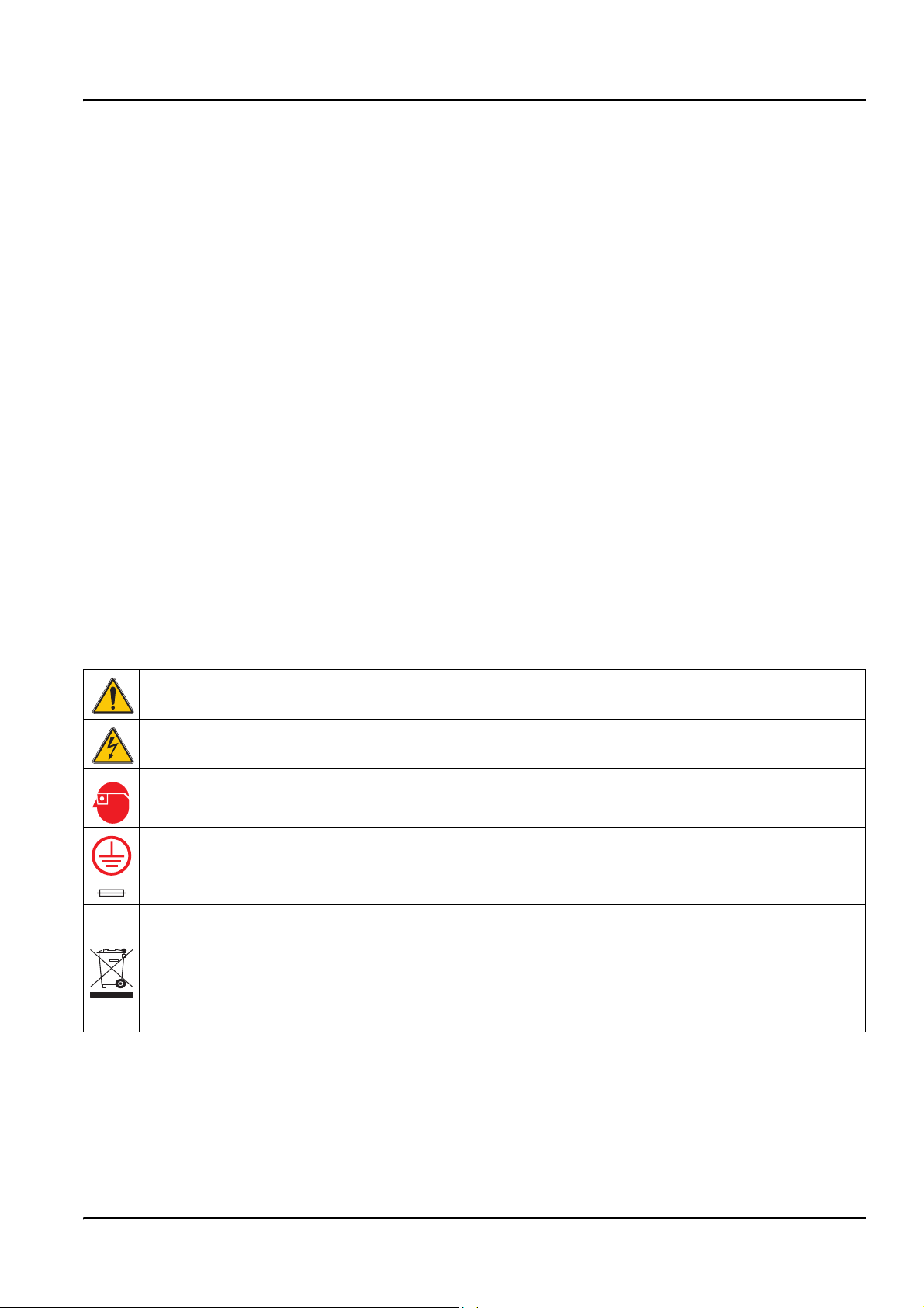
2.1.2 Precautionary Labels
Read all labels and tags attached to the instrument. Personal injury or damage to the
instrument could occur if not observed
This symbol, if noted on the instrument, references the instruction manual for operation
and/or safety information.
This symbol, when noted on a product enclosure or barrier, indicates that a risk of electrical shock and/or
electrocution exists.
This symbol, if noted on the product, indicates the need for protective eye wear.
This symbol, when noted on the product, identifies the location of the connection for
Protective Earth (ground).
This symbol, when noted on the product, identifies the location of a fuse or current limiting device.
Electrical equipment marked with this symbol may not be disposed of in European public disposal
systems after 12 August of 2005. In conformity with European local and national regulations (EU
Directive 2002/96/EC), European electrical equipment users must now return old or end-of life equipment
to the Producer for disposal at no charge to the user.
.
Note: For all electrical products (marked or unmarked) which are supplied or produced by Hach-Lange, please
contact the local Hach-Lange sales office for instructions for proper disposal.
3
Page 10
General Information
2.2 General Sensor Information
Optional equipment, such as mounting hardware for the probe, is supplied with
instructions for all user installation tasks. Several mounting options are available, allowing
the probe to be adapted for use in many different applications.
The electronics of the sensor are encapsulated in a PEEK
sensor has an integral NTC 300 ohm thermistor to automatically compensate pH readings
for temperature changes. ORP sensors have a fixed temperature value of 25 °C/300 ohm
(the ORP measurement is not temperature dependent).
2.2.1 Sensor Body Styles
pHD™ Differential pH and ORP sensors are available in three body styles:
• Convertible Body Style — has 1-inch NPT threads at both ends of the body for
mounting in any of the following configurations:
• into a standard 1-inch NPT pipe tee
• into a pipe adapter for union mounting with a standard 1-½ inch pipe tee
• onto the end of a pipe for immersion into a vessel
Note: The convertible style sensor can also be retrofitted into existing installations for 1-½ inch LCP,
Ryton, and epoxy sensors.
• Insertion Body Style — similar to the convertible sensor except that its
1-inch NPT threads are only on the cable end for mounting into a flow cell or the pipe
adapter of a ball valve hardware assembly. This hardware enables the sensor to be
inserted into or retracted from the process without stopping the process flow.
• Sanitary Body Style — features a built-in 2-inch flange for mounting into a 2-inch
sanitary tee. Included with the sanitary-style sensor is a special cap and EDPM
compound gasket for use with the sanitary hardware.
®
or Ryton® body. The pH
In addition, all probes are available with or without integral digital electronics.
For applications with extreme temperatures, the sensor without integral digital electronics
can be combined with the digital gateway.
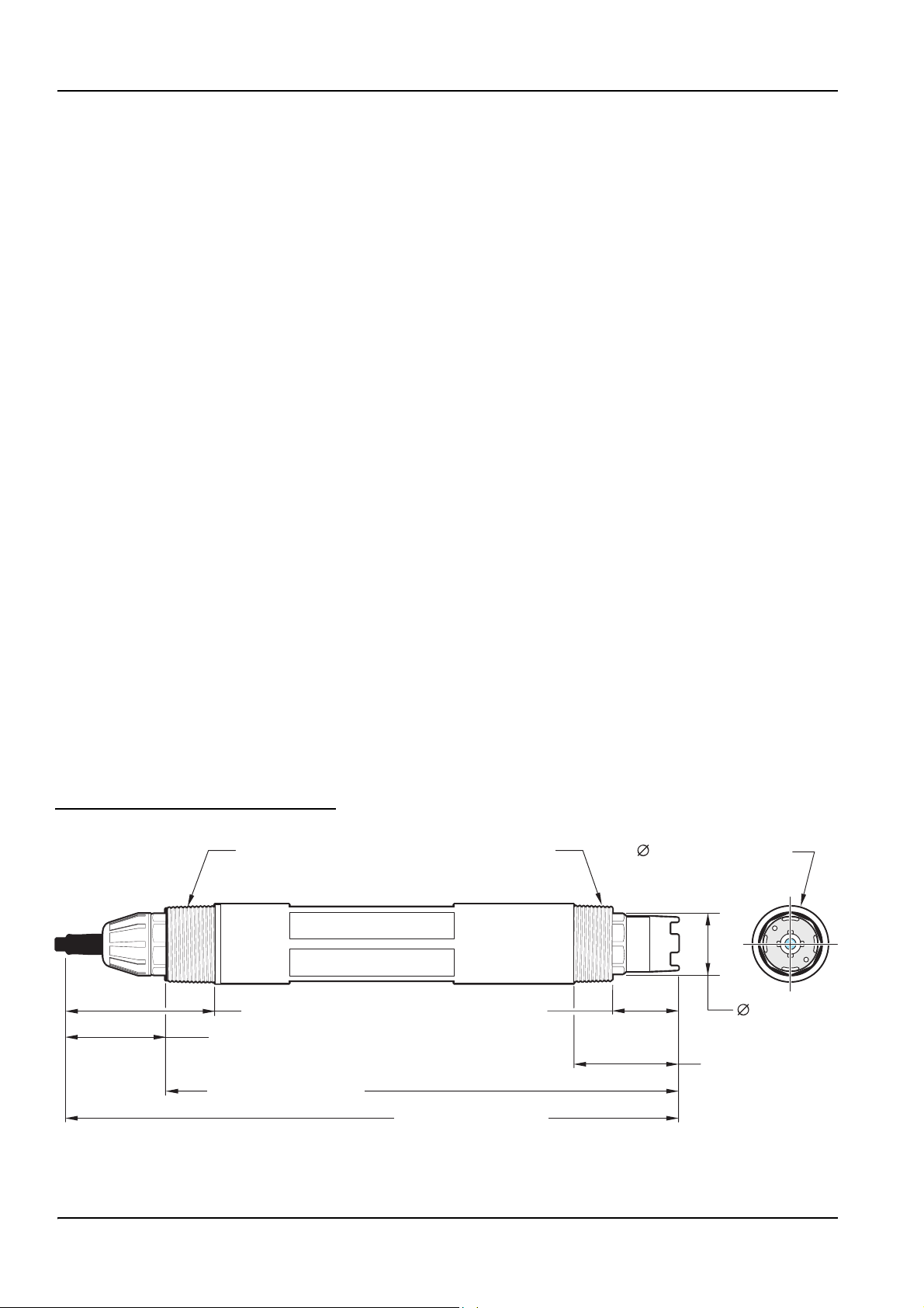
Figure 1 Convertible Style Sensor Dimensions
1-inch NPT 1-inch NPT
59.44 mm (2.34 inches)
39.11 mm (1.54 inches)
232.15 mm (9.14 inches)
29.5 mm (1.16 inches)
271.3 mm (10.68 inches)
35.4 mm (1.36 inches)
26.7 mm
(1.05 inches)
49.8 mm (1.96 inches)
4
Page 11
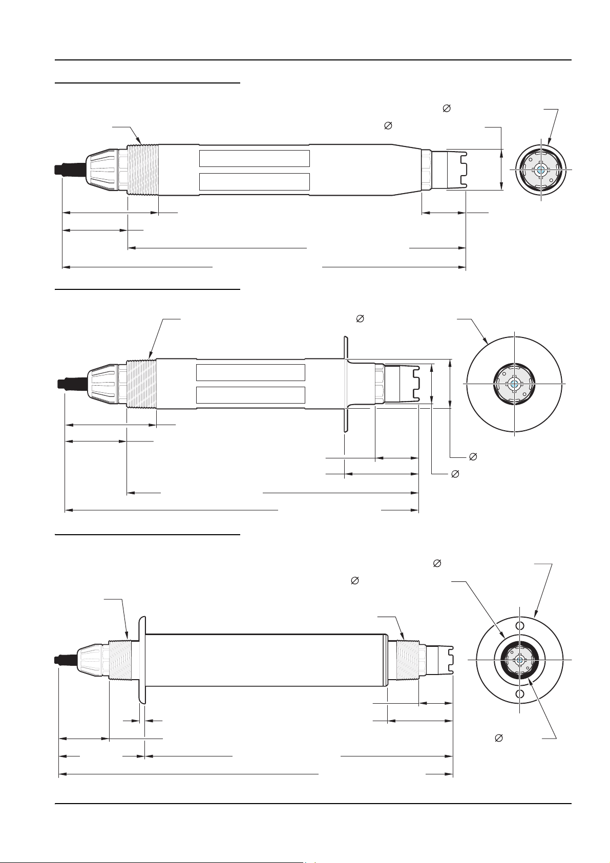
Figure 2 Insertion Style Sensor Dimensions
General Information
35.4 mm (1.36 inches)
1-inch NPT
59.44 mm (2.34 inches)
39.11 mm (1.54 inches)
271.3 mm (10.68 inches)
Figure 3 Sanitary Style Sensor Dimensions
1-inch NPT
26.7 mm (1.05 inches)
29.5 mm
(1.16 inches)
232.15 mm (9.14 inches)
54.6 mm (2.15 inches)
59.44 mm (2.34 inches)
39.11 mm (1.54 inches)
29.5 mm (1.16 inches)
49.8 mm (1.96 inches)
232.15 mm (9.14 inches)
271.3 mm (10.68 inches)
Figure 4 Stainless Steel Style Sensor (DPS1 and DRS5) Dimensions
43.9 mm (1.73 inches)
1-inch NPT
1-inch NPT
29.5 mm (1.16 inches)
4.5 mm (0.179 inches)
57.2 mm (2.25 inches)
34.8 mm (1.37 inches)
26.7 mm (1.05 inches)
54.6 mm (2.15 inches)
59.4 mm
(2.34 inches)
35.8 mm (1.41 inches)
264.67 mm (10.42 inches)
32.8 mm
(1.29 inches)
324.0 mm (12.755 inches)
5
Page 12

General Information
2.3 The Digital Gateway
The digital gateway was developed to provide a means to use existing analog sensors with
the new digital controllers. The gateway contains all the necessary software and hardware
to interface with the controller and output a digital signal.
2.4 Operating Precaution
CAUTION
If the pH process electrode breaks, handle the sensor very carefully to
prevent injury.
Before placing the pH or ORP sensor into operation, remove the protective cap to expose
the process electrode and salt bridge. Save the protective cap for future use.
For short-term storage (when sensor is out of the process for more than one hour) fill the
protective cap with pH 4 buffer or DI water and place the cap back on the sensor. Keeping
the process electrode and salt bridge moist will avoid slow response when the sensor is
placed back in operation.
For extended storage, repeat the short-term storage procedure every 2 to 4 weeks,
depending on the surrounding environmental conditions. See Specifications on page 1 for
temperature storage limits.
The process electrode at the tip of the pH sensor has a glass bulb, which can be broken.
Do not subject it to abrupt impact or other mechanical abuse.
The gold or platinum process electrode at the ORP sensor tip has a glass shank (hidden
by the salt bridge) which can break. Do not subject this electrode to impact or other
mechanical abuse.
6
Page 13
Section 3 Installation
DANGER
Only qualified personnel should conduct the tasks described in this section of the
manual.
3.1 Connecting/Wiring the Sensor to the sc Controller
3.1.1 Attaching a sc Sensor with a Quick-connect Fitting
The sensor cable is supplied with a keyed quick-connect fitting for easy attachment to the
controller (Figure 5). Retain the connector cap to seal the connector opening in case the
sensor must be removed. Optional extension cables may be purchased to extend the
sensor cable length. If the total cable length exceeds 100 m (300 ft), a termination box
must be installed.
Note: Use of a load termination box other than Cat. No. 5867000 may result in a hazard.
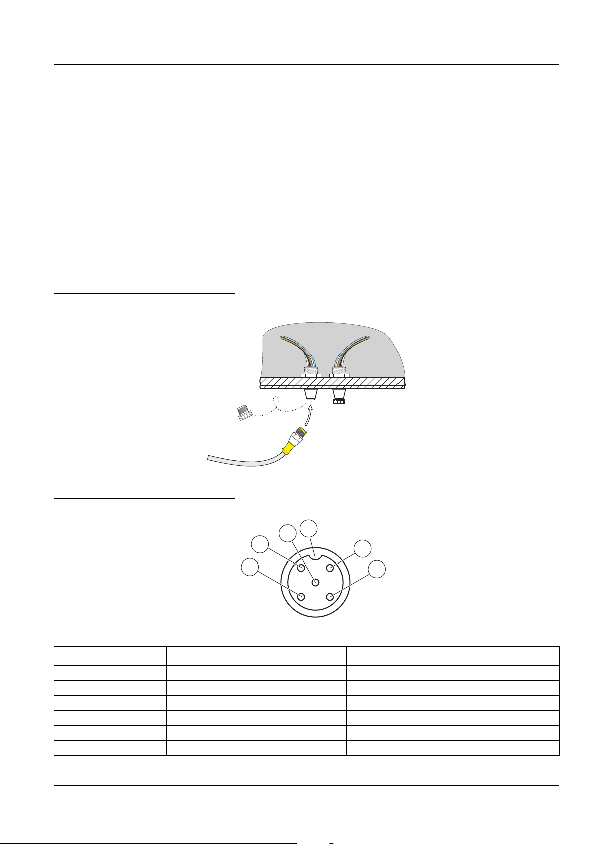
Figure 5 Attaching the Sensor using the Quick-connect Fitting
Figure 6 Quick-connect Fitting pin assignment
5
4
3
Number Designation Wire Color
1+12 VDC Brown
2 Circuit Common Black
3 Data (+) Blue
4 Data (–) White
5 Shield Shield (grey wire in existing quick-disconnect fitting)
6Groove
6
1
2
7
Page 14
Installation
3.2 Using the Digital Gateway
The digital gateway is designed to provide a digital interface to the controller.
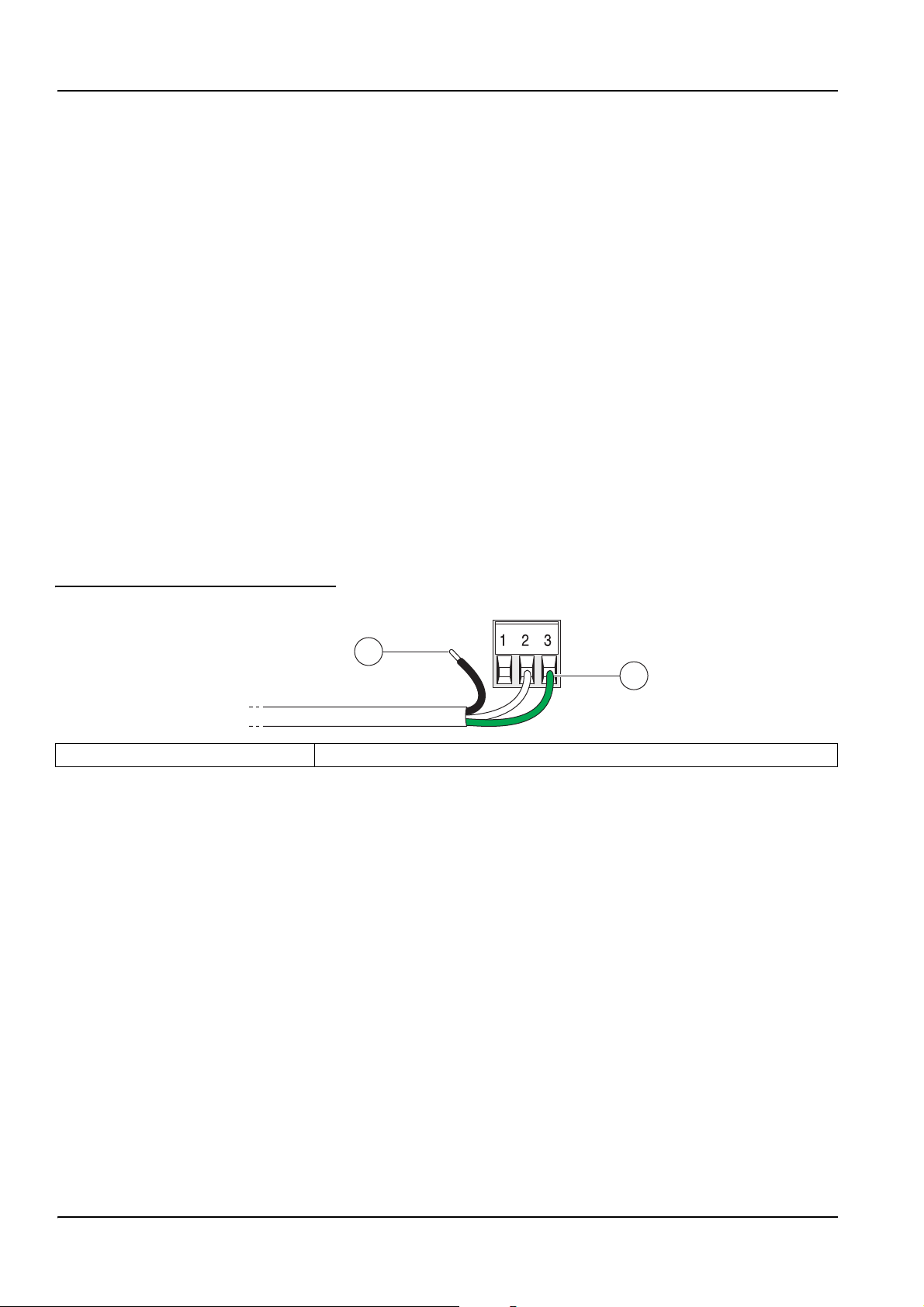
3.2.1 Wiring the Digital Gateway
DANGER
Explosion hazard. Do not connect or disconnect equipment unless power has been
switched off or the area is known to be non-hazardous.
1. Route the cable from the sensor through the strain relief in the digital gateway then
properly terminate the wire ends (see Figure 7).
Note: Do not tighten the strain relief until the digital gateway is wired and the two halves are
threaded securely together.
2. Insert the wires as shown in Table 3 and Figure 8.
3. Make sure the O-ring is properly installed between the two halves of the digital
gateway and thread the two halves together. Hand tighten.
4. Tighten the strain relief to secure the sensor cable.
5. Connect the digital gateway to the controller.
Figure 7 Proper Wire Preparation and Insertion
1
2
1. Strip ¼-inch of insulation. 2. Seat insulation against connector with no bare wire exposed.
8
Page 15

Figure 8 Wiring and Assembling the Digital Gateway
Installation
1. Digital gateway front 7. Cord grip
2. O-ring 8. From sensor
3. Sensor wire connector 9. Insert wires into connector according to Table 3. Use the included 2 mm
screwdriver (Cat. No. 6134300) to secure connections.
4. Digital gateway back 10. Screw back of digital gateway onto front.
5. Cable bushing 11. Push cable bushing and anti-rotation washer into back.
6. Anti-rotation washer 12. Fasten cord grip securely. Assembly is complete.
9
Page 16

Installation
Table 3 Wiring the Digital Gateway (Cat. No. 6120500)
Sensor (wire color) Sensor Signal Digital Gateway J1
Green Ref J1-1
Yel l ow Te m p + J1 - 2
Black Temp – J1-3
White VI J1-4
Red Active J1-5
Clear Shield J1-6
Clear w/shrink wrap Shield J1-6
3.2.2 Mounting the Digital Gateway
The digital gateway is supplied with a mounting clip for mounting to a wall or other flat
surface. See Figure 9 for dimensions. Use an appropriate fastener to secure it to the wall,
see Figure 10. After the sensor is wired to the digital gateway and the two halves are
threaded together, place the mounting clip over the center of the digital gateway and
squeeze the clip together to secure.
Figure 9 Digital Gateway Dimensions
34.29 mm
(1.35 inches)
Figure 10 Mounting the Digital Gateway
184.15 mm (7.25 inches)
1. Mounting Clip 3. Hex Nut, ¼-28
2. Screw, pan head, ¼-28 x 1.25-in. 4. Mount clip, insert digital gateway, squeeze clip closed.
10
Page 17

3.3 Installing the Sensor in the Sample Stream
aa
aa
aa
aa
aa
aa
aa
aa
• Install the sensor so the sample contacts is representative of the entire process.
• Mount the sensor at least 508 mm (20 in) from the aeration basin wall, and immerse it
at least 508 mm (20 in) into the process.
• Install the sensor using the instructions supplied with the installation apparatus. See
Figure 11 for suggested mounting configurations.
Figure 11 Sensor Installation Examples
Installation
1. Sanitary mount 5. PVC Insertion mount
2. Union mount 6. Stainless steel insertion mount
3. Flow-through mount 7. Immersion mount
4. Hanging stainless steel sensor with the bale 8. Immersion mount, ball float
11
Page 18

Installation
12
Page 19

Section 4 Operation
4.1 Using an sc Controller
Before using the sensor in combination with an sc controller make yourself familiar with
the operating mode of the controller. Refer to the controller user manual and learn how to
use and navigate the menu functions.
4.2 Sensor Setup
When a sensor is initially installed, the serial number of the sensor will be displayed as the
sensor name. To change the sensor name refer to the following instructions:
1. Select Main Menu.
2. From the Main Menu, select SENSOR SETUP and confirm.
3. Highlight the appropriate sensor if more than one sensor is attached and confirm.
4. Select CONFIGURE and confirm.
5. Select EDIT NAME and edit the name. Confirm or cancel to return to the Sensor
Setup menu.
4.3 Sensor Data Logging
The sc controller provides one data log and one event log for each sensor. The data log
stores the measurement data at selected intervals. The event log stores a variety of events
that occur on the devices such as configuration changes, alarms, warning conditions, etc.
The data log and the event log can be read out in a CSV format. For downloading the logs
please refer to the controller user manual.
4.4 Sensor Diagnostics Menu for pH and ORP
SELECT SENSOR
ERROR LIST–See section 6.1 on page 23.
WARNING LIST–See section 6.2 on page 23.
4.5 pH Sensor Setup Menu
SELECT SENSOR (if more than one sensor is attached)
CALIBRATE
1 POINT AUTO
Calibration with a single buffer — normally pH 7.
2 POINT AUTO
Calibration with two buffers — normally pH 7 and pH 4 or 10.
1 POINT MANUAL
Calibration against a single known sample.
2 POINT MANUAL
Calibration against two samples, both with a known pH.
13
Page 20

Operation
4.5 pH Sensor Setup Menu (continued)
TEMP ADJUST
Adjust the displayed temperature by up to ± 15 °C.
DEFAULT SETUP
Restores the system to the original factory calibration.
CONFIGURE
EDIT NAME
Enter up to a 10-digit name in any combination of symbols and alpha or numeric characters.
SELECT MEASURE
Select the appropriate measurement units to display.
DISPLAY FORMAT
Select the measurement resolution (xx.xx pH or xx.x pH).
TEMP UNITS
Choose from the displayed options (°C or °F).
LOG SETUP
Choose SENSOR INTERVAL to set the sensor log interval or select TEMP INTERVAL to set the temperature log interval.
REJECT FREQ
Choose 50 or 60 Hz depending on the power line frequency for optimal noise rejection. Default is 60 Hz.
FILTER
Select 0–60 second signal averaging time.
TEMP ELEMENT
Select type of temperature element from the displayed choices.
SELECT BUFFER
Select the buffer type (standard 4, 7, 10 or DIN 19267) from the displayed choices.
PURE H20 COMP
Allows the user to specify that ammonia, morpholine, or other user-defined electrolyte is being used in the application,
allowing a temperature-dependent linear slope factor to be applied to the measured pH.
CAL DAYS
Number of days since the last calibration. Default notification at 60 days.
SENSOR DAYS
Number of days the sensor has been in operation. Default notification at 365 days.
DEFAULT SETUP
Resets all user-editable options to their factory-defaults.
DIAG/TEST
PROBE INFO
Display the sensor type, entered name of the sensor (Default: sensor serial number.), the sensor serial number, the
software version number, and the sensor driver version number.
CAL DATA
Displays the pH slope and the date of the last calibration.
14
Page 21

4.5 pH Sensor Setup Menu (continued)
SIGNALS
SENSOR SIGNAL: Displays the sensor output in mV
SENSOR ADC COUNTS: Displays the sensor ADC counts
TEMP ADC COUNTS: Displays raw data for temperature ADC counts. ADC counts are comparable to A/D counts and
are for sensor electronic diagnostic purposes only.
ELECTRODE STATE: Identifies the state of the electrode (good or bad) depending on whether the impedance is within
preset limits.
ACTIVE ELECT: Displays the impedance (Mohms) of the active electrode if Imped Status is set to Enabled.
REF. ELECTRODE: Displays the impedance (Mohms) of the reference electrode if Imped Status is set to Enabled.
IMPED STATUS: Sensor diagnostic. Choose Enabled or Disabled.
COUNTERS
SENSOR DAYS: displays the cumulative days the sensor has been in use.
RESET SENSOR: Allows the sensor counter to be reset to zero.
ELECTRODE DAYS: Cumulative days the electrode has been in use.
4.6 ORP Sensor Setup Menu
Operation
SELECT SENSOR (if more than one sensor is attached)
CALIBRATE
1 POINT MANUAL
Calibration against a single known sample.
TEMP ADJUST
Adjust the displayed temperature by up to ± 15 °C.
DEFAULT SETUP
Restores the system to the original factory calibration.
CONFIGURE
EDIT NAME
Enter up to a 10-digit name in any combination of symbols and alpha or numeric characters. Press
is complete. The name will be displayed on the status line with the measurement value.
SELECT SENSOR
Choose from the displayed sensor type (pH or ORP).
TEMP UNITS
Choose from the displayed options (°C or °F).
LOG SETUP
Choose SENSOR INTERVAL to set the sensor log interval or select TEMP INTERVAL to set the temperature log interval.
ENTER when the entry
AC FREQUENCY
Choose 50 or 60 Hz depending on the power line frequency for optimal noise rejection. Default is 60 Hz.
CONFIGURE (continued)
FILTER
Select 0–60 second signal averaging time.
TEMP ELEMENT
Select type of temperature element from the displayed choices.
15
Page 22

Operation
4.6 ORP Sensor Setup Menu (continued)
CAL DAYS
Number of days since the last calibration. Default notification at 60 days.
SENSOR DAYS
Number of days the sensor has been in operation. Default notification at 365 days.
IMPED LIMITS
Set min/max electrode sensor impedance limits.
DEFAULT SETUP
Resets all user-editable options to their factory-defaults.
DIAG/TEST
PROBE INFO
Display the sensor type, entered name of the sensor (Default: sensor serial number.), the sensor serial number, the
software version number, and the sensor driver version number.
CAL DATA
Displays the slope and the date of the last calibration.
SIGNALS
SENSOR SIGNAL: displays the sensor output in mV
SENSOR ADC COUNTS: displays the sensor ADC counts
TEMP ADC COUNTS: shows raw data for temperature ADC counts. ADC counts are comparable to A/D counts and are for
sensor electronic diagnostic purposes only.
ELECTRODE STATE: Identifies the state of the electrode (good or bad) depending on whether the impedance is within
preset limits.
ACTIVE ELECT: Shows the impedance (Mohms) of the active electrode if Imped Status is set to Enabled.
REF. ELECTRODE: Shows the impedance (Mohms) of the reference electrode if Imped Status is set to Enabled.
IMPED STATUS: Sensor diagnostic. Choose Enabled or Disabled.
COUNTERS
SENSOR DAYS: displays the cumulative days the sensor has been in use. RESET SENSOR: allows the sensor counter to
be reset to zero. ELECTRODE DAYS: Cumulative days the electrode has been in use.
16
Page 23

4.7 pH Calibration
The manufacturer offers one and two point automatic and manual calibrations for pH. An
automatic calibration identifies the buffer table corresponding to the chosen buffer and
automatically calibrates the probe after it stabilizes. A manual calibration is performed by
placing the pH sensor in any buffer or sample with a known value and then entering that
known value into the controller.
The value of the sample used in the manual calibration may be determined by laboratory
analysis or comparison reading.
1. From the Main Menu, select SENSOR SETUP and confirm.
2. Select the appropriate sensor if more than one is attached and confirm.
3. Select CALIBRATE and confirm.
4. Select 1 POINT AUTO. Select the available Output Mode (Active, Hold, or Transfer)
5. Move the clean probe to buffer and confirm to continue.
Operation
from the list box and confirm.
6. Confirm when stable. A screen will display 1 Point Auto Complete and the slope
(XX.X mV/pH).
7. Return the probe to process.
4.7.1 Two Point Automatic Calibration
1. From the Main Menu, select SENSOR SETUP and confirm.
2. Select the appropriate sensor if more than one is attached and confirm.
3. Select CALIBRATE and confirm.
4. Select 2 POINT AUTO. Select the available Output Mode (Active, Hold, or Transfer)
from the list box and confirm.
5. Move the clean probe to Buffer 1 and confirm.
6. Confirm when stable.
7. Move the clean probe to Buffer 2 and confirm.
8. Confirm when stable. A screen will display 2 Point Calibration Complete and the slope
(XX.X mV/pH).
9. Return the probe to process.
4.7.2 One Point Manual Calibration
1. From the Main Menu, select SENSOR SETUP and confirm.
2. Select the appropriate sensor if more than one is attached and confirm.
3. Select CALIBRATE and confirm.
17
Page 24

Operation
4. Select 1 POINT MANUAL. Select the available Output Mode (Active, Hold, or Transfer)
from the list box and confirm.
5. Move the clean probe to solution and confirm to continue.
6. Confirm when stable. Edit the solution value using the keypad and confirm.
7. Confirm when stable. A screen will display 1 Point Manual Complete and the slope
(XX.X mV/pH).
8. Return the probe to process.
4.7.3 Two Point Manual Calibration
1. From the Main Menu, select SENSOR SETUP and confirm.
2. Select the appropriate sensor if more than one is attached and confirm.
3. Select CALIBRATE and confirm.
4. Select 2 POINT MANUAL CAL. Select the available Output Mode (Active, Hold, or
Transfer) from the list box and confirm.
5. Move the clean probe to Solution 1 and confirm.
6. Confirm when stable. Edit the solution value using the keypad and confirm.
7. Move probe to solution 1 and confirm.
8. Confirm when stable. Edit the solution value using the keypad and confirm.
9. A screen will display 2 Point Manual Cal Complete and the slope (XX.X mV/pH).
10. Return the probe to process.
18
Page 25

4.8 ORP Calibration
The manufacturer offers a one point manual calibration for ORP. The value of the sample
used in the manual calibration may be determined by laboratory analysis or comparison
reading.
1. From the Main Menu, select SENSOR SETUP and confirm.
2. Select the appropriate sensor if more than one is attached and confirm.
3. Select CALIBRATE and confirm.
4. Select 1 POINT MANUAL CAL. Select the available Output Mode (Active, Hold, or
Transfer) from the list box and confirm.
5. Move the clean probe to Solution and confirm.
6. Confirm when stable. Edit the solution value using the keypad and confirm.
7. A screen will display 1 Point Manual Complete and the slope (XX.X mV).
8. Return the probe to process.
Operation
4.9 Concurrent Calibration of Two Sensors for pH and ORP
1. Begin a calibration on the first sensor and continue until “Wait to Stabilize”
is displayed.
2. Select LEAVE and confirm. The display will return to the main measurement screen.
The reading for the sensor currently being calibrated will flash.
3. Begin the calibration for the second sensor and continue until “Wait to Stabilize”
is displayed.
4. Select LEAVE and confirm. The display will return to the main measurement screen
and the reading for both sensors will flash. The calibration for both sensors are now
running in the background.
5. To return to the calibration of either sensor select SENSOR SETUP from the Main
Menu and confirm. Select the appropriate sensor and confirm.
6. The calibration in progress will be displayed. Continue with the calibration.
19
Page 26

Operation
4.10 Adjusting the Temperature
View or change the temperature using the steps below.
1. From the Main Menu, select SENSOR SETUP and confirm.
2. Select the appropriate sensor if more than one is attached and confirm.
3. Select CALIBRATE and confirm.
4. Select TEMP ADJUST and confirm.
5. Select MEASURED TEMP and confirm.
6. The temperature will be displayed. Tap on the temperature and edit the temperature
using the keypad and confirm.
20
Page 27

Section 5 Maintenance
DANGER
Only qualified personnel should conduct the tasks described in this section of the
manual.
DANGER
Explosion hazard. Do not connect or disconnect equipment unless power has been
switched off or the area is known to be non-hazardous.
5.1 Maintenance Schedule
Maintenance Task 90 days Annually
1
Clean the sensor
Inspect sensor for damage x
Replace Salt Bridge and fill solution
Calibrate Sensor (as required by regulatory agency) Per the schedule mandated by your regulatory agency.
1
Cleaning frequency is application dependent. More or less frequent cleaning will be appropriate in some applications.
2
Salt bridge replacement frequency is application dependent. More or less frequent replacement will be appropriate in some
applications
x
2
x
5.2 Cleaning the Sensor
CAUTION
Before cleaning with acid, determine if the chemical reaction between the acid and
the sample will create a hazardous chemical reaction. (For example, do not put a
sensor that is used in a cyanide bath directly into a strong acid for cleaning
because this chemical combination may produce poisonous cyanide gas.)
1. Clean the exterior of the sensor with a stream of water. If debris remains remove loose
contaminate buildup by carefully wiping the entire measuring end of the sensor
(process electrode, concentric metal ground electrode, and salt bridge) with a soft
clean cloth. Rinse the sensor with clean, warm water.
2. Prepare a mild soap solution of warm water and dish detergent or other non-abrasive
soap that does not contain lanolin such as laboratory glass cleaner.
Note: Lanolin will coat the glass process electrode and can adversely affect sensor performance.
3. Soak the sensor for 2 to 3 minutes in the soap solution.
4. Use a small soft bristle brush (such as a toothbrush) and scrub the entire measuring
end of the sensor, thoroughly cleaning the electrode and salt bridge surfaces. If
surface deposits cannot be removed by detergent solution cleaning, use muriatic acid
(or other dilute acid) to dissolve them. The acid should be as dilute as possible.
Experience will determine which acid to use and the appropriate dilution ratio. Some
stubborn coatings may require a different cleaning agent.
DANGER
Acids are hazardous. Always wear appropriate eye protection and clothing in
accordance with material safety data sheet recommendations.
5. Soak the entire measuring end of the sensor in dilute acid for no more than 5 minutes.
Rinse the sensor with clean, warm water then place the sensor back into the mild
soap solution for 2 to 3 minutes to neutralize any remaining acid.
21
Page 28

Maintenance
6. Remove the sensor from the soap solution, and rinse the sensor again in clean, warm
water.
7. After cleaning, always calibrate the measurement system.
5.2.1 Replacing the Standard Cell Solution and Salt Bridge
If calibration cannot be attained, rejuvenate the sensor by replacing its standard cell
solution and salt bridge as shown in Figure 12. If calibration is still not possible, refer to
Section 6 on page 23.
1. To remove the salt bridge, hold the sensor upright (electrode at top), and use pliers or
a similar tool to turn it counterclockwise. Take care not to damage the protruding
process electrode. Properly discard the old salt bridge.
2. Replace the standard cell solution in the sensor reservoir.
a. Pour out the aged solution, and thoroughly flush the reservoir with distilled water.
b. Fill the reservoir to the bottom of the salt bridge threads with fresh standard cell
solution (Cat. No. 25M1A1025-115).
3. Install a new o-ring then carefully thread the new salt bridge clockwise until it is
finger-tight and the bottom surface of the salt bridge is in full contact with the top
surface of the sensor body. Do not over tighten.
Figure 12 Replacing Standard Cell Solution and Salt Bridge
1 2
1. Salt Bridge 2. Sensor
22
Page 29

Section 6 Troubleshooting
6.1 Error Codes
Errors are defined in Table 4.
Tabl e 4 Er ror Cod e s
Displayed Error Definition Resolution
ADC FAILURE System measurement fails Contact Technical Consulting Services.
6.2 Warnings
Errors are defined in Table 5.
Table 5 Warning Codes
Displayed Warning Definition Resolution
PROBE OUT RANGE
TEMP OUT RANGE
FLASH FAILURE System flash memory write has failed. Contact Technical Consulting Services.
ACTIVE. ELEC
REF. ELECTRODE
CAL REQUIRED
REPLACE SENSOR
Measured pH/ORP exceeds the expected
value range.
Measured temperature exceeds the
expected value range.
Standard electrode is not performing within
the required specifications.
Reference electrode is not performing
within the required specifications.
60 days has elapsed since the last
calibration
One year has elapsed since the sensor has
been installed.
Contact Technical Consulting Services.
Contact Technical Consulting Services.
Contact Technical Consulting Services.
Contact Technical Consulting Services.
Perform a calibration.
Replace sensor and restore counter in the
SENSOR SETUP>DIAG/TEST>RESET SENSOR
menu
23
Page 30

Troubleshooting
6.3 Troubleshooting the pH Sensor
Clean the sensor using the procedure described in section 5.2 on page 21. If the
measuring system cannot be calibrated after cleaning, replace the standard cell solution
and salt bridge (see section 5.2.1 on page 22) and try calibrating again. If the measuring
system still cannot be calibrated, check the sensor operation.
Some simple tests using the sc100 or a multimeter and two pH buffers will determine if the
pH sensor is operating properly. The use of pH 7 and pH 4 buffers is preferred but pH 10
can be used in place of pH 4 if it more closely covers the measurement range of interest.
Determine if the sensor has integral digital electronics or uses an external digital gateway.
If the sensor uses a digital gateway, it will be hard-wired to the gateway through terminal
connections inside the digital gateway enclosure. If the sensor uses the digital gateway
and therefore does not have integral digital electronics, proceed with section 6.3.1. If the
sensor has integral digital electronics, move to section 6.3.2 on page 25.
6.3.1 Troubleshooting a pH Sensor without Integral Digital Electronics
1. Disconnect the red, green, yellow, and black sensor wires from the digital gateway.
2. Place the sensor in a pH 7 buffer. Before continuing, allow the temperatures of the
sensor and buffer to equalize to approximately 25 °C (70 °F).
3. Verify that the sensor temperature element (300 ohm thermistor) is operating properly
by measuring the resistance between the yellow and black wires. The reading should
be between 250 and 350 ohms at approximately 25 °C (70 °F).
4. Reconnect the yellow and black wires.
5. Connect the multimeter (+) lead to the red wire and (–) lead to the green wire. With the
sensor in the pH 7 buffer, measure the dc millivolts. The sensor offset reading should
be within the factory-specified limits of –50 and +50 mV. If it is, record the millivolt
value reading and continue with step 6. If the reading is outside these limits,
discontinue this test and contact Technical Support.
6. With the multimeter still connected, rinse the sensor with water and place it in either
pH 4 or pH 10 buffer. Allow the temperatures of the sensor and buffer to equalize to
approximately 25 °C (70 °F) then measure the sensor span reading as shown in
Table 6 and Table 7 on page 25.
Span Reading in pH 4 Buffer
With the sensor in pH 4 buffer, the sensor span reading should be at least +160 mV more
than the offset reading taken in step 5.
Table 6 Typical Span Reading Examples (pH 4 buffer)
24
Offset Reading
(in pH 7 buffer)
–50 mV +110 mV
–25 mV +135 mV
0 mV +160 mV
+25 mV +185 mV
+50 mV +210 mV
Span Reading (in pH 4 buffer)
Page 31

Troubleshooting
Span Reading in pH 10 Buffer
With the sensor in pH 10 buffer, the sensor span reading should be at least –160 mV less
than the noted offset reading taken in step 5.
Table 7 Typical Span Reading Examples (pH 10 buffer)
Offset Reading
(in pH 7 buffer)
–50 mV –210 mV
–25 mV –185 mV
0 mV –160 mV
+25 mV –135 mV
+50 mV –110 mV
If the span reading is at least +160 mV more than or
Span Reading (in pH 10 buffer)
–160 mV less than the offset reading
in pH 4 or pH 10, respectively, the sensor is within factory-specified limits. If not, contact
Technical Support.
6.3.2 Troubleshooting the pH Sensor with Integral Digital Electronics
1. Place the sensor in pH 7 buffer and allow the buffer and sensor to reach temperature
equilibrium. This can be verified by monitoring the sensor temperature value for a
stable temperature measurement. This value is shown on the sc controller display
when it is in measurement mode.
2. From the Sensor Setup Menu on the sc controller, select “Diag/Test” and confirm.
3. Select “Sensor Signal” and confirm. This sensor offset reading should be within
factory-specified limits of –50 and +50 mV. If it is, write down this millivolt value
reading and perform step 4. If the reading is outside these limits, discontinue this test
and contact Technical Support.
4. Rinse the sensor and place it in pH 4 or 10 buffer and allow the buffer and sensor to
reach temperature equilibrium. This can be verified by monitoring the sensor
temperature value for a stable temperature measurement. This value is located on the
sc100 display when it is in measurement mode.
5. From the Sensor Setup Menu on the sc controller, select “Diag/Test” and confirm.
6. Select “Sensor Signal” and confirm. Then measure the sensor span value.
Span Reading in pH 4 Buffer
With the sensor in pH 4 buffer, the sensor span reading should be at least +160 mV more
than the offset reading as shown in Table 8 and Table 9.
Table 8 Typical Span Reading Examples (pH 4 buffer)
Offset Reading (in pH 7 buffer) Span Reading (in pH 4 buffer)
–50 mV +110 mV
–25 mV +135 mV
0 mV +160 mV
+25 mV +185 mV
+50 mV +210 mV
25
Page 32

Troubleshooting
Span Reading in pH 10 Buffer
With the sensor in pH 10 buffer, the sensor span reading should be at least –160 mV less
than the noted offset reading taken in step 6. Examples of typical readings:
Table 9 Typical Span Reading Examples (pH 10 buffer)
Offset Reading (in pH 7 buffer) Span Reading (in pH 10 buffer)
–50 mV –210 mV
–25 mV –185 mV
0 mV –160 mV
+25 mV –135 mV
+50 mV –110 mV
7. If the span reading is at least +160 mV more than or
reading in pH 4 or pH 10, respectively, the sensor is within factory-specified limits.
If not, contact Technical Support.
–160 mV less than the offset
6.4 Checking ORP Sensor Operation
Simple tests using the sc controller or a multimeter and a 200 mV reference solution can
determine if the ORP sensor is operating properly. Determine if the sensor has integral
digital electronics or uses an external digital gateway. If the sensor uses a digital gateway,
it will be hard-wired to the digital gateway through terminal connections within the digital
gateway enclosure. If the sensor uses a digital gateway proceed with section 6.4.1. If the
sensor has integral digital electronics, move to section 6.4.2 on page 26.
6.4.1 Troubleshooting the ORP Sensor without Integral Digital Electronics
1. Disconnect the red, green, yellow, and black sensor wires from the digital gateway.
2. Place the sensor in a 200 mV reference solution and allow the temperature of the
sensor and reference solution to equalize to approximately 25 °C (70 °F).
3. Verify that the sensor temperature element (300 ohm thermistor) is operating by
measuring the resistance between the yellow and black wires. The reading should be
between 250 and 350 ohms at approximately 25 °C (70 °F).
4. Reconnect the yellow and black wires.
5. Connect the multimeter (+) lead to the red wire and (–) lead to the green wire. With the
sensor in the 200 mV reference solution, measure the dc millivolts. The reading
should be between 160 and 240 mV. If the reading is outside these limits, contact
Technical Support.
6.4.2 Troubleshooting the ORP Sensor with Integral Digital Electronics
1. Place the sensor in 200 mV reference solution and allow the buffer and sensor to
reach temperature equilibrium. This can be verified by monitoring the sensor
temperature value for a stable temperature measurement. This value is located on the
sc100 display when it is in measurement mode.
2. From the Sensor Setup Menu on the sc controller, select “Diag/Test” and confirm.
Select “Sensor Signal” and confirm. The reading should be between 160 and 240 mV.
If the reading is outside these limits, contact Customer Service.
26
Page 33

Section 7 Replacement Parts and Accessories
7.1 Replacement Items, Accessories, and Reagent and Standards
Item Description QTY Catalog Number
Air blast cleaning system, 115 V, includes Kynar® (PVDF) washer head with 7.6 m
(25 ft) tubing and quick connect fitting, and a compressor in a NEMA 4X enclosure
Air blast cleaning system, 230 V, includes Kynar
(25 ft) tubing and quick connect fitting, and a compressor in a NEMA 4X enclosure
Air/Water blast cleaning head each 1000A3335-004
Buffer, pH 7 500 mL (1 pint) 2283549
Buffer, pH 4 500 mL (1 pint) 2283449
Buffer, pH 10 500 mL (1 pint) 2283649
Buffer, pH 7 1 gallon 2283556
Buffer, pH 4 1 gallon 2283456
Buffer, pH 10 1 gallon 2283656
Buffer, pH 7 500 mL (1 pint) 2283549
Cable, interconnect, unterminated ends, specify length in whole feet each 1W1100
Cable, sensor extension, 1 m (3 ft) each 6122400
Cable, sensor extension, 7.7 m (25 ft) each 5796000
Cable, sensor extension, 15 m (50 ft) each 5796100
Cable, sensor extension, 31 m (100 ft) each 5796200
Connector Cable each 6139900
Instruction manual, Differential pH System, English each DOC023.52.03251
Plug, sealing, conduit opening each 5868700
O-ring, Viton each 5H1304
O-ring, EPDM each 5H1306
O-ring, Perflouro each 5H1096-019
ORP Standard Solution, 200 mV 500 mL (1 pint) 25M2A1001-115
ORP Standard Solution, 600 mV 500 mL (1 pint) 25M2A1002-115
ORP Standard Solution, 200 mV 1 gallon 25M2A1001-123
ORP Standard Solution, 600 mV 1 gallon 25M2A1002-123
®
Salt Bridge, PEEK
Salt Bridge Ryton® Body, PVDF outer junction each SB-R1SV
Standard Cell Solution each 25M1A1025-115
Strain relief, Heyco each 16664
Body, PVDF outer junction each SB-P1SV
®
(PVDF) washer head with 7.6 m
each 1000A3335-005
each 1000A3335-006
27
Page 34

Replacement Parts and Accessories
28
Page 35

Section 8 Warranty, liability and complaints
HACH LANGE GmbH warrants that the product supplied is free of material and
manufacturing defects and undertakes the obligation to repair or replace any defective
parts at zero cost.
The warranty period for instruments is 24 months. If a service contract is taken out within 6
months of purchase, the warranty period is extended to 60 months.
With the exclusion of the further claims, the supplier is liable for defects including the lack
of assured properties as follows: all those parts that can be demonstrated to have become
unusable or that can only be used with significant limitations due to a situation present
prior to the transfer of risk, in particular due to incorrect design, poor materials or
inadequate finish will be improved or replaced, at the supplier's discretion. The
identification of such defects must be notified to the supplier in writing without delay,
however at the latest 7 days after the identification of the fault. If the customer fails to notify
the supplier, the product is considered approved despite the defect. Further liability for any
direct or indirect damages is not accepted.
If instrument-specific maintenance and servicing work defined by the supplier is to be
performed within the warranty period by the customer (maintenance) or by the supplier
(servicing) and these requirements are not met, claims for damages due to the failure to
comply with the requirements are rendered void.
Any further claims, in particular claims for consequential damages cannot be made.
Consumables and damage caused by improper handling, poor installation or incorrect use
are excluded from this clause.
HACH LANGE GmbH process instruments are of proven reliability in many applications
and are therefore often used in automatic control loops to provide the most economical
possible operation of the related process.
To avoid or limit consequential damage, it is therefore recommended to design the control
loop such that a malfunction in an instrument results in an automatic change over to the
backup control system; this is the safest operating state for the environment and the
process.
29
Page 36

8.1 Compliance Information
Immunity
This equipment was tested for industrial level EMC per:
EN 61326 (EMC Requirements for Electrical Equipment for Measurement, Control
and Laboratory Use)
Company, certified compliance by Hach Company.
Standards include:
IEC 1000-4-2:1995 (EN 61000-4-2:1995) Electrostatic Discharge Immunity (Criteria
B)
IEC 1000-4-3:1995 (EN 61000-4-3:1996) Radiated RF Electromagnetic Field
Immunity (Criteria A)
IEC 1000-4-4:1995 (EN 61000-4-4:1995) Electrical Fast Transients/Burst (Criteria B)
IEC 1000-4-5:1995 (EN 61000-4-5:1995) Surge (Criteria B)
IEC 1000-4-6:1996 (EN 61000-4-6:1996) Conducted Disturbances Induced by RF
Fields (Criteria A)
IEC 1000-4-11:1994 (EN 61000-4-11:1994) Voltage Dip/Short Interruptions (Criteria
B)
Additional Immunity Standard/s include:
per 89/336/EEC EMC: Supporting test records by Hach
Emissions
ENV 50204:1996 Radiated Electromagnetic Field from Digital Telephones (Criteria A)
This equipment was tested for Radio Frequency Emissions as follows:
Per 89/336/EEC EMC: EN 61326:1998 (Electrical Equipment for measurement,
control and laboratory use—EMC requirements) Class “A” emission limits. Supporting
test records by Hewlett Packard, Fort Collins, Colorado Hardware Test Center (A2LA #
0905-01) and certified compliance by Hach Company.
Standards include:
EN 61000-3-2 Harmonic Disturbances Caused by Electrical Equipment
EN 61000-3-3 Voltage Fluctuation (Flicker) Disturbances Caused by
Electrical Equipment
Additional Emissions Standard/s include:
EN 55011 (CISPR 11), Class “A” emission limits
30
Page 37

Section 9 Contact
HACH LANGE GmbH
Willstätterstraße 11
D-40549 Düsseldorf
Tel. +49 (0) 211- 52 88 - 0
Fax +49 (0) 211- 52 88 - 143
info@hach-lange.de
www.hach-lange.de
DR. BRUNO LANGE
GES. MBH
Industriestraße 12
A-3200 Obergrafendorf
Tel. +43 (0) 2747 - 74 12
Fax +43 (0) 2747 - 42 18
info@hach-lange.at
www.hach-lange.de
DR. LANGE NEDERLAND B.V.
Laan van Westroijen 2a
NL-4003 AZ Tiel
Tel. +31(0)3 44 63 11 30
Fax +31(0)3 44 63 11 50
info@hach-lange.nl
www.hach-lange.nl
HACH LANGE LTD
Pacific Way
Salford
Manchester, M50 1DL
Tel. +44 (0)161 8 72 14 87
Fax +44 (0)161 8 48 73 24
info@hach-lange.co.uk
www.hach-lange.co.uk
DR. BRUNO LANGE AG
Juchstrasse 1
CH-8604 Hegnau
Tel. +41 (0)1- 9 45 66 10
Fax +41 (0)1- 9 45 66 76
info@hach-lange.ch
www.hach-lange.ch
HACH LANGE AB
Vinthundsvägen159A
S-128 62 Sköndal
Tel. +46 (0)8 7 98 05 00
Fax +46 (0)8 7 98 05 30
info@hach-lange.se
www.hach-lange.se
HACH LANGE
HACH SAS
33, Rue du Ballon
F-93165 Noisy Le Grand
Tél. +33 (0)1 48 15 8080
Fax +33 (0)1 48 15 80 00
info@hach-lange.fr
www.hach-lange.fr
HACH LANGE SA
Motstraat 54
B-2800 Mechelen
Tél. +32 (0)15 42 35 00
Fax +32 (0)15 41 61 20
info@hach-lange.be
www.hach-lange.be
HACH LANGE A/S
Åkandevej 21
DK-2700 Brønshøj
Tel. +45 36 77 29 11
Fax +45 36 77 49 11
info@hach-lange.dk
www.hach-lange.dk
HACH LANGE S.L.U.
C/Araba 45, Apdo. 220
E-20800 Zarautz/Guipúzcoa
Tel. +34 9 43 89 43 79
Fax +34 9 43 13 02 41
info@hach-lange.es
www.hach-lange.es
HACH LANGE S.R.O.
Lešanská 2a/1176
CZ-141 00 Praha 4
Tel. +420 272 12 45 45
Fax +420 272 12 45 46
info@hach-lange.cz
www.hach-lange.cz
HACH LANGE SP.ZO.O.
ul. Opolska 143 a
PL-52-013 Wroclaw
Tel. +48 71 3 42 10-81
Fax +48 71 3 42 10-79
info@hach-lange.pl
www.hach-lange.pl
HACH LANGE S.R.O.
Sabinovská 10
SK-821 02 Bratislava
Tel. +421 2 4820 9091
Fax +421 2 4820 9093
info@hach-lange.sk
www.hach-lange.com
HACH LANGE S.R.L.
Via Riccione, 14
I-20156 Milano
Tel. +39 02 39 23 14-1
Fax +39 02 39 23 14-39
info@hach-lange.it
www.hach-lange.it
31
Page 38

Appendix A General pH Information
A.1 pH Measurement Theory
pH is the negative logarithm of the hydrogen ion activity and a measure of the acidity or
alkalinity of a solution.
pH = –log A[H+]
pH is normally measured using a glass electrode and a reference electrode.
The glass electrode acts as a transducer, converting chemical energy (the hydrogen ion
activity) into an electrical energy (measured in millivolts). The reaction is balanced and the
electrical circuit is completed by the flow of ions from the reference solution to the solution
under test.
The electrode and reference solution together develop a voltage (emf) whose magnitude
depends on the type of reference electrode, the internal construction of the glass
electrode, the pH of the solution and the temperature of the solution. This voltage is
expressed by the Nernst Equation:
E = Eo – (2.3 RT/F) x log A[H+]
E = Eo – (slope) x log A[H+]
where:
E = the emf of the cell
E
= the zero potential (isopotential) of the system. It depends on the internal
o
construction of the glass and reference electrodes.
R = gas constant
T = temperature in Kelvin
A[H+] = activity of the hydrogen ion (assumed to be equivalent to the concentration of
hydrogen ions)
F = Faraday constant
For every unit change in pH (or decade change in ion concentration) the emf of the
electrode pair changes by 59.16 mV at 25 °C. This value is known as the Nernstian Slope
of the electrode.
The pH electrode pair is calibrated using solutions of known and constant hydrogen ion
concentration, called buffer solutions. The buffer solutions are used to calibrate both the
electrode isopotential and slope.
32
Page 39

A.2 PID Controller Basics
A pH control loop operates as follows: The pH meter measures the value of the pH in the
effluent, and, if the pH is different from the setpoint, the controller actuates the reagent
pump (or valve) that adds reagent to a mixing tank. The added reagent adjusts the pH
value of the process.
The physical layout of the loop, the sizing of the pump (valve), type of mixing tank, and
location of the pH electrodes all have a major impact on the ultimate performance of the
loop, after the controller is tuned for optimal performance. The largest single performance
factor is the delay time around the loop. This includes the response time of the
electrode/meter, time required to deliver the reagent to the process water, time required for
the reagent to mix with and react with the process water, and the time required to deliver
the completely mixed water to the electrode. If the delay times are too long or the mixing is
not complete, the control will be poor regardless of how well the controller is tuned.
The Process pH Meter uses a PID (proportional, integral (reset), derivative (rate) control)
control algorithm. Each of the instrument settings along with their effects on the control
loop, are described below.
Mode
Manual: The manual output is specified in percent of full-scale PID output
(4–20 mA) and is commonly used for testing the output device.
General pH Information
Auto: Allows the process to be controlled automatically using information specified in the
Phase, Setpoint, Proportional Band, Integral, and Derivative menus as follows:
Phase
Direct: The control output action will cause the process value to increase.
Reverse: The control output action will cause the process value to decrease.
Setpoint
The setpoint is defined as the desired process value in pH
Proportional Band
The proportional band is the range in pH from the setpoint value where the controller
provides proportional control. For example, the desired setpoint for the process is pH 7.0
and the process requires that a reagent must be added to the process water to bring it up
to pH 7.0. If the proportional band is set to pH 1.0, the controller will provide proportional
output control over the range of pH 6.0 to 8.0. When the process is at pH 6.0, the
controller will provide a 100% control output level (assuming that Phase is set to Direct).
When the process is at pH 7.0, the proportional control will provide a 0% control output
level. When the process is at pH 6.5 the proportional control will provide a 50% output.
The output action is equal to the difference between the setpoint and the process value,
divided by the proportional band value.
33
Page 40

General pH Information
Integral
The integral value is used to reduce the steady state error, between the process value and
the setpoint, to zero. For example, assume a process can be manually controlled at a level
of pH 8.0 by sending a 35% control output level to a reagent pump. Now, say that the
system is set up for the controller to provide proportional only control, with the controller
setpoint set to pH 8.0 and the proportional band set to pH 1.0. Note that the nearer the
process gets to the pH 8.0 setpoint, the lower the control output level is. In fact, when the
process is at pH 8.0, the output level will be 0%. Since the process requires that the pump
be operated at 35% for the process to reach pH 8.0, its apparent that proportional-only
control will never quite reach the desired setpoint of pH 8.0. This is where the integral
control comes in.
Integral control can be thought of as adding up the output action from the proportional
control over time. For example, the proportional control output reaches a steady state level
of 5%. If the integral time is set to five minutes, the integral action of the controller will add
an additional 5% to the controller output level over a 5-minute interval. The integral action
is additive, so for every 5-minute interval an additional 5% is added to the controller's
output level. This will allow the controller to bring the process to the desired setpoint level.
Note that the longer the integral time setting, the longer it takes for the integral action to
affect the process. The integral control action is disabled by setting it to zero. Note that the
integral time is in minutes.
Derivative
Derivative control is used to adjust the control output level based upon the rate at which
the process value is approaching or passing the setpoint. Derivative control action would
be used in cases where the process value can rapidly ramp up and overshoot the setpoint.
The derivative setting is in minutes. The output action of the derivative control is equal to
the rate of change of the process (in pH units per minute) times the derivative time, divided
by the proportional band, times negative one. For example, if the process pH is changing
at a rate of pH 0.20 per minute, the derivative time is set to 3.0 minutes, the proportional
band is set to pH 0.80, and the action is “direct” the derivative control output action will be
approximately equal to: (–0.20 pH/minute X 3.0 minute) /0.80 pH = –75%.
During calibration, the analog outputs can remain active, be held, or be transferred to a
preset mA value.
34
Page 41

Appendix B Modbus Register Information
Table 10 Sensor Modbus Registers
Group Name Tag Name Register # Data Type Length R/W Description
Tags SensorMeasTag 40001 Integer 1 R Sensor measurement tag
Measurements pHMeas 40002 Float 2 R pH /ORP measurement
Tags TempMeasTag 40004 Integer 1 R Temperature measurement tag
Measurements TempDegCMeas 40005 Float 2 R Temperature measurement
Configuration SensorName 40007 String 6 R/W Sensor name
Tags FuncCode 40013 Integer 1 R/W Function code tag
Tags NextState 40014 Integer 1 R/W Next state tag
Configuration MeasType 40015 Integer 1 R/W Measurement type-pH or ORP
Configuration TempUnits 40016 Integer 1 R/W Temperature units-C or F
Configuration pHFormat 40017 Integer 1 R/W pH display format
Configuration TaggedPhFormat 40018 Long 2 R pH display tagged format
Configuration Filter 40020 Integer 1 R/W Sensor filter
Configuration TempElementType 40021 Integer 1 R/W Temperature element type
Tags TempUserValueTag 40022 Integer 1 R Temperature user value tag
Configuration TempUserDegCValue 40023 Float 2 R/W Temperature user value
Configuration pHBuffer 40025 Integer 1 R/W pH buffer type
Configuration PureWaterCompType 40026 Integer 1 R/W Pure H
Configuration PureWaterCompUser 40027 Float 2 R/W Pure H
Calibration OutputMode 40029 Integer 1 R/W Output mode
Calibration CalLeave 40030 Integer 1 R/W Cal leave mode
Calibration CalAbort 40031 Integer 1 R/W Cal abort mode
Tags CalEditValueTag 40032 Integer 1 R Cal edit value tag
Calibration CalEditPhValue 40033 Float 2 R/W Cal edit value
Diagnostics pHSlope 40035 Float 2 R pH slope
Diagnostics SoftwareVersion 40037 String 6 R Software version
Diagnostics SerialNumber 40043 String 6 R Serial number
Diagnostics pHOffset 40049 Float 2 R pH offset
Diagnostics OrpOffset 40051 Float 2 R Orp offset
Calibration CalCode 40053 Integer 1 R Cal code
Configuration SensorLogInterval 40054 Integer 1 R/W Sensor data log interval
Configuration TempLogInterval 40055 Integer 1 R/W Temperature data log interval
Diagnostics pHmV 40056 Float 2 R pH mV
Diagnostics ProdDate 40058 Date 2 R/W Production date
Diagnostics StdElectrode 40060 Float 2 R Standard electrode impedance
Diagnostics RefElectrode 40062 Float 2 R Reference electrode impedance
Diagnostics LastCalDate 40064 Date 2 R Last calibration date
Diagnostics SensorDays 40066 Integer 1 R Sensor running days
Diagnostics ElectrodeDays 40067 Integer 1 R Electrode running days
Diagnostics ElectrodeStatus 40068 Integer 1 R Electrode status
O compensation type
2
O compensation user val
2
35
Page 42

Modbus Register Information
Table 10 Sensor Modbus Registers (continued)
Group Name Tag Name Register # Data Type Length R/W Description
Diagnostics SensorType 40069 Integer 1 R Sensor type
Configuration RejectFrequency 40070 Integer 1 R/W Reject frequency
Diagnostics DeviceDriver 40071 String 5 R Device driver
Configuration CalWarningDays 40076 Integer 1 R/W Calibration warning days
Configuration SensorWarningDays 40077 Integer 1 R/W Sensor warning days
36
Page 43

Index
D
Derivative ................................................................. 33
Derivative (Rate) Control
......................................... 33
E
Error Codes .............................................................. 23
I
Integral ..................................................................... 33
Integral (Reset)
........................................................ 33
M
Maintenance Schedule ............................................ 21
P
Parts
Replacement
..................................................... 27
PID control
Proportional
Proportional
Proportional Band
....................................................... 33
.............................................................. 33
.................................................... 33
S
Safety Information ...................................................... 3
Sensor Cable
Connecting
Wiring
Specifications
.......................................................... 7
.................................................................. 7
............................................................. 1
W
Warnings .................................................................. 23
Warranty
.................................................................. 29
37
Page 44

38
 Loading...