

Page 1
DOC022.52
User Manual
Conductivity Probe: Model CDC40101, CDC40103, CDC40105,
CDC40110, CDC40115 or CDC40130
Safety information
Precautionary labels
Read all labels and tags attached to the instrument. Personal injury or damage to the
instrument could occur if not observed. A symbol on the instrument is referenced in the
manual with a precautionary statement.
Electrical equipment marked with this symbol may not be disposed of in European public disposal systems after
12 August of 2005. In conformity with European local and national regulations (EU Directive 2002/96/EC), European
electrical equipment users must now return old or end-of-life equipment to the Producer for disposal at no charge to
the user.
Note: For return for recycling, please contact the equipment producer or supplier for instructions on how to return end-of-life
equipment, producer-supplied electrical accessories, and all auxiliary items for proper disposal.
Specifications
Note: Specifications are subject to change without notice.
.80022
Specifications Details
Probe type Graphite, 4-pole conductivity probe
Conductivity range 0.01 μS/cm to 200.0 mS/cm
Cell constant 0.40 cm-1 ±10%
Conductivity resolution 0.0 to 19.99 μS/cm: 0.01 μS/cm
20.0 to 199.9 μS/cm: 0.1 μS/cm
200 to 1999 μS/cm: 1
2.00 to 19.99 mS/cm: 0.01 mS/cm
20.0 to 200.0 mS/cm: 0.1 mS/cm
Conductivity accuracy ±0.5% of reading
TDS (total dissolved solids) range 0 to 50,000 mg/L as NaCl
TDS resolution 0.0 to 19.99 mg/L: 0.01 mg/L
200 to 1999 mg/L: 1 mg/L
2.00 to 19.99 g/L: 0.01 g/L
20.0 to 50.0 g/L: 0.1 g/L
TDS accuracy ±0.5% of reading
Sample salinity range 0 to 42 (ppt) (‰)
Salinity resolution 0.01 parts per thousand (ppt) (‰)
μS/cm
Salinity accuracy ±1 parts per thousand (ppt) (‰)
Temperature accuracy ±0.3 °C (±0.54 °F)
Operating temperature range -10 to 110 °C (14 to 230 °F)
Storage temperature range 5 to 40 °C (41 to 104 °F)
Minimum sample depth 45 mm (1.77 in.)
Dimensions (standard) Diameter: 15 mm (0.59 in.)
Length: 184 mm (7.24 in.)
Cable length: 1 or 3 m (3.28 or 9.84 ft)
1
Page 2
Specifications Details
Dimensions (rugged) Diameter: 46 mm (1.81 in.)
Length: 223 mm (8.73 in.)
Cable length: 5, 10, 15 or 30 m (16.40, 32.81, 49.21 or 98.42 ft)
Cable connection M12 digital output and connector compatible with HQd meters
Product overview
The CDC401 series probe is a graphite, 4-pole conductivity probe (Figure 1). The
CDC40101 or CDC40103 standard conductivity probe is available with a 1 or 3 m (3.28 or
9.84 ft) cable and is intended for laboratory use. The CDC40105, CDC40110,
CDC40115 or CDC40130 rugged conductivity probe is available with a 5, 10, 15 or 30 m
(16.40, 32.81, 49.21 or 98.42 ft) cable. The probe measures electrical conductivity,
salinity, resistivity or total dissolved solids (TDS) in wastewater, drinking water and
general applications.
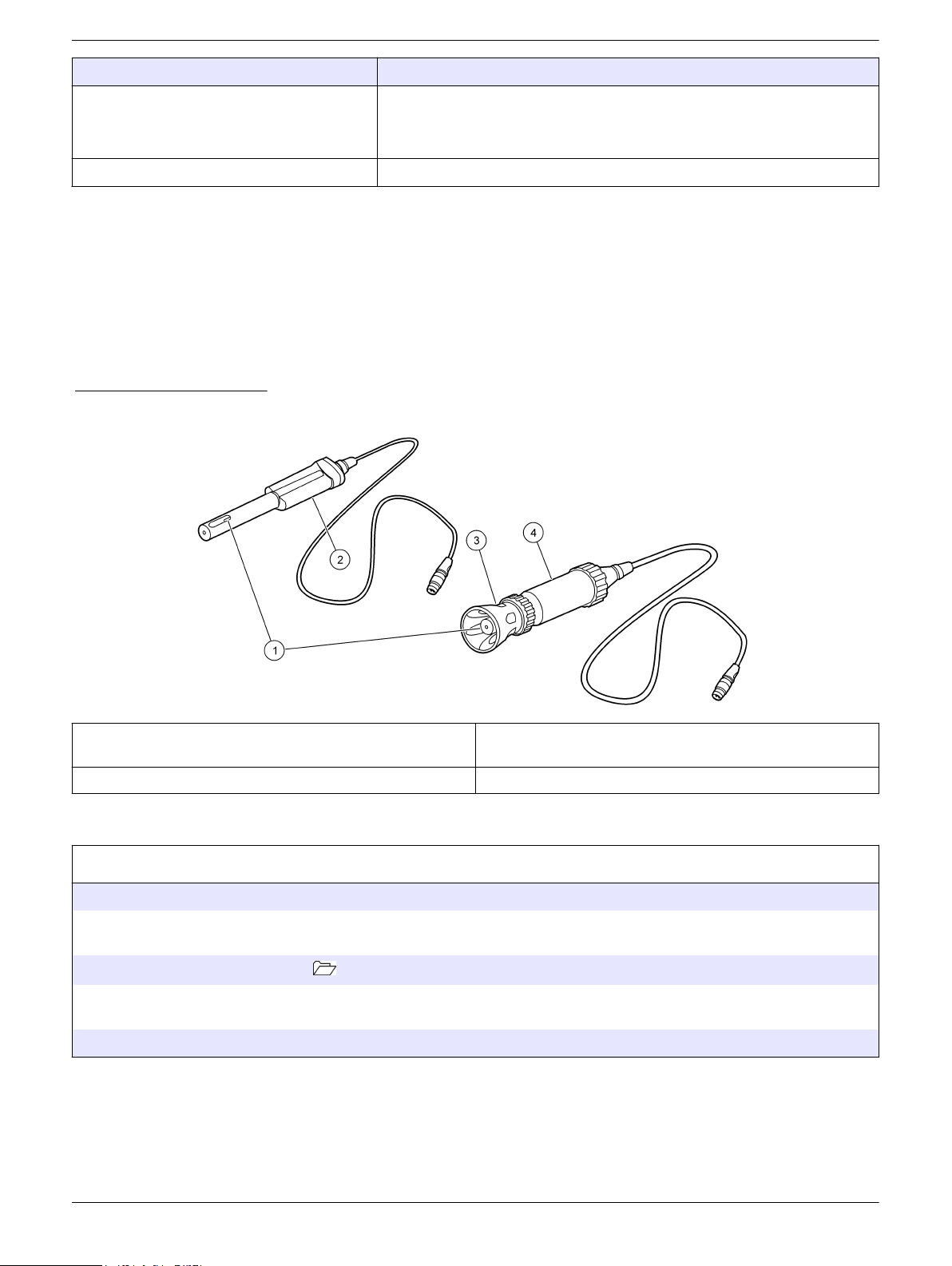
Figure 1 Probe overview
1 Temperature sensor and 4-pole graphite design
conductivity cell
2 Standard probe (1 or 3 meter cable) 4 Rugged probe (5, 10, 15, or 30 meter cable)
3 Shroud (rugged model)
Calibration
Before calibration:
The probe must have the correct service-life time stamp. Set the date and time in the meter before the probe is attached.
It is not necessary to recalibrate when moving a calibrated probe from one HQd meter to another if the additional meter is
configured to use the same calibration options.
To view the current calibration, push , select View Probe Data, then select View Current Calibration.
If any two probes are connected, push the UP or DOWN arrow to change to the single display mode in order to show the
Calibrate option.
If a rugged probe, remove the shroud from the probe (refer to Remove the shroud
Calibration notes:
Do not touch the tip of the probe.
•
• Additional conductivity standards can be selected in the Calibration Options menu.
• The cell constant is derived from the calibration standard.
• Do not dilute conductivity standards and samples.
on page 8).
2
Page 3
• The meter will automatically correct the calibration measurement to the selected
reference temperature (20 or 25 °C) using the default NaCl-based, non-linear
temperature coefficient. Settings can be changed in the CDC401 Calibration Options
menu.
The calibration is recorded in the probe and the data log. The calibration is also sent
•
to a PC, printer or flash memory stick if connected.
• Air bubbles under the sensor tip when submerged can cause slow response or error
in measurement. If bubbles are present, gently shake the probe until bubbles are
removed.
• If a calibration error occurs, refer to Troubleshooting on page 9.
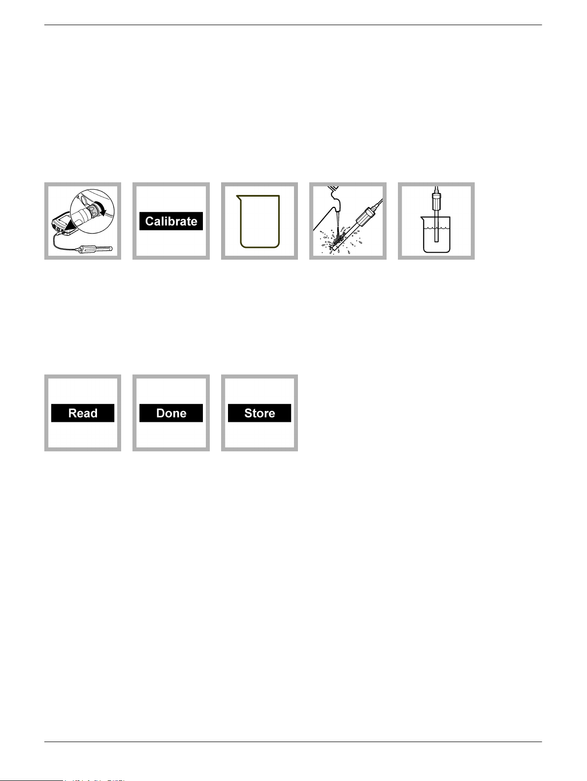
Calibration procedure:
1. Connect the
probe to the
meter. Make sure
that the cable
locking nut is
securely
connected to the
meter. Turn on the
meter.
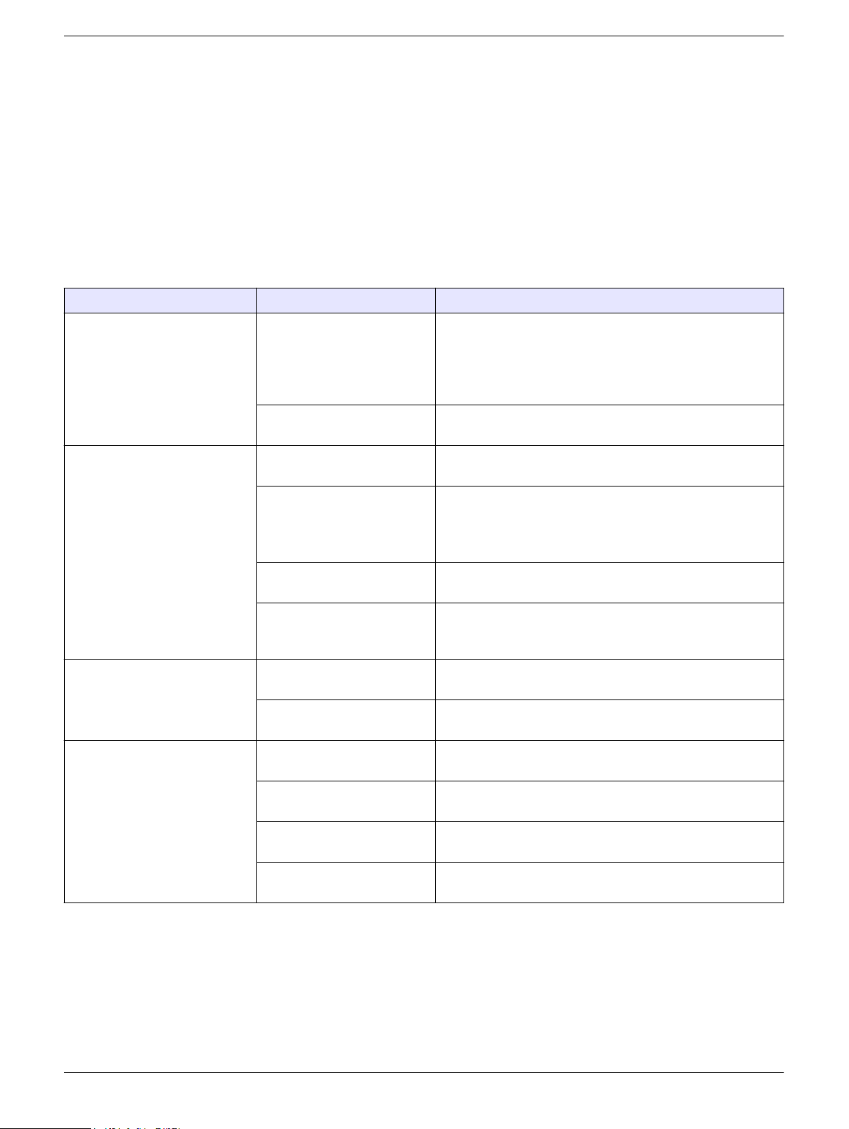
6. Push Read.
Stir gently. The
display will show
"Stabilizing" and a
progress bar as
the probe
stabilizes in the
standard. The
display shows the
standard solution
value that has just
been read and
shows the
temperature
corrected value
when the reading
is stable.
2. Push
Calibrate. The
display shows the
conductivity
standard solution
that is necessary
for calibration.
7. Push Done to
view the
calibration
summary.
3. Add fresh
conductivity
standard solution
to a beaker or an
appropriate
container.
8. Push Store to
accept the
calibration and
return to the
measurement
mode. If a rugged
probe, install the
shroud on the
probe (refer to
Install the shroud
on page
9).
4. Rinse the
probe with
deionized water.
Blot dry with a lintfree cloth.
5. Put the probe
in the standard
solution and stir
gently. Make sure
that the
temperature
sensor is
completely
submerged.
3
Page 4

Sample measurement
Before measurement:
The probe must have the correct service-life time stamp. Set the date and time in the meter before the probe is attached.
If complete traceability is necessary, enter a sample ID and operator ID before measurement. Refer to the HQd meter
manual for more information.
To display other parameters (TDS, salinity or resistivity), push , select CDC401 Settings and then Current Method.
When using the CDC401 probe with the LDO101 probe to do auto salinity correction, set the CDC401 probe to measure
salinity. Refer to Change measurement options on page 6.
Regular calibration is required for the best measurement accuracy (refer to Calibration on page 2).
If a rugged probe, make sure that the shroud is installed. Damage to the sensing elements can occur if the shroud is not
installed during field use. Damage under these conditions is not covered by the product warranty.
To deploy a rugged probe at a distance, toss the probe body with a gentle underhand throw. Do not swing the probe by the
cable as this may cause injury to the user, will cause severe strain on the cable and will shorten the service life of the probe.
Measurement notes:
•
Do not touch the tip of the probe.
• Stabilization times with smaller concentration changes generally will be longer and
can be minimized by correct stirring and conditioning. Experiment to determine the
correct stir rate if necessary.
• Data is automatically stored in the data log when Press to Read or Interval is
selected in the Measurement Mode. When Continuous is selected, data will only be
stored when Store is selected.
• Air bubbles under the sensor tip when submerged can cause slow response or error
in measurement. If bubbles are present, gently shake the probe until bubbles are
removed.
• If a measurement error occurs, refer to Troubleshooting on page 9.
1. Connect the
probe to the
meter. Make sure
that the cable
locking nut is
securely
connected to the
meter. Turn on the
meter.
Measurement procedure:
Note: Procedure also applies for rugged model probes.
2. Rinse the
probe with
deionized water.
Blot dry with a lintfree cloth.
3. Put the probe
into the sample so
that the
temperature
sensor is
completely
submerged. Do
not put the probe
on the bottom or
sides of the
container.
4. Push Read.
The display will
show "Stabilizing"
and a progress
bar as the probe
stabilizes in the
sample. The
display will show
the lock icon when
the reading
stabilizes. The
measurement is
automatically
corrected to the
selected reference
temperature (20 or
25 °C).
5. Repeat steps
2 - 4 for additional
measurements.
When
measurements
are done, store
the probe (refer to
Storage
on page
9).
4
Page 5

Run a check standard
The run check standard feature validates instrument performance between sample
measurements. Use the run check standard feature for periodic or user-defined interval
measurements of a traceable standard solution. Set the criteria for check standards from
the CDC401
Note: Access control must be off or a valid password must be entered before any of the check
standard method options can be changed.
Settings menu.
1. Push
2. Select Run Check Standard.
Note: Select the correct probe if two probes are connected to the meter.
3. Get the standard solution shown on the display.
4. Rinse the probe with deionized water. Blot dry with a lint-free cloth.
5. Put the probe in the standard solution until the temperature sensor is completely
submerged. Move the probe up or down or gently tap on the beaker to remove air
bubbles from the probe.
6. Push Read. The display will show "Stabilizing" and a progress bar as the reading
stabilizes. The display shows the value of the check standard and either Check
Standard Passed or Check Standard Failed.
7. If the display shows Check Standard Passed, the check standard measurement is
within the accepted limits set by the administrative user. Select Done to continue with
the sample measurement.
8. If the display shows Check Standard Failed, the measurement is outside of
accepted limits set by the administrative user and a recalibration is recommended. If
the acceptance criteria is set to Cal Expires on Failure: Yes, the display shows the
calibration icon and a question mark until the probe is recalibrated. To correct the
probe calibration and status indicator, calibrate the probe (refer to Calibration
on page
Advanced operation
Parameter-specific settings can be changed through the Full Access Options menu.
Details about menu navigation, available options and how to change them are given in
the screens, tables and procedures throughout this section.
. The Full Access Options menu is shown.
2).
The settings that can be changed are shown in Table 1.
Table 1 Parameter-specific settings
Setting Options
Parameter
Measurement Options
• Conductivity
Salinity
•
• TDS
• Resistivity
• Units
• Measurement limits
• Temperature correction
• Correction factor (if linear temperature correction is selected)
• Reference temperature (if a temperature correction is selected)
5
Page 6

Table 1 Parameter-specific settings (continued)
Setting Options
Calibration Options
Check Standards Options
• Standard
•
• Standard units (if Custom option is selected)
• Standard value (if Custom option is selected)
• Reference temperature (if Custom option is selected)
• Temperature correction (if Custom option is selected)
• Standard solution for calibration verification
• Reminder
• Acceptance criteria
Change measurement options
Methods are groups of default or user-defined settings relevant to specific applications. If
the meter is set to the default method and the Modify Current Settings option is chosen, a
prompt for a new name is shown after the changes are entered. The settings are saved
with this name to distinguish them from the default method settings, which cannot be
changed. A saved method can be used instead of multiple adjustments to the individual
settings. Changes made to a user defined method are automatically saved with the
existing name. Multiple methods can be saved for the same probe on each meter.
Table 2 lists the five default methods available for the CDC401 conductivity cell.
Calibration reminder
Table 2 Default methods
Options Description
Hach Conductivity Default method with conductivity measurement values.
Conductivity is typically used for natural water samples.
Hach TDS Default method with TDS measurement values. TDS is typically used to estimate the amount of total
dissolved solids in the sample. The conductivity value is also shown in the Detailed Reading screen.
Hach Salinity Default method with salinity measurement values. Salinity is typically used for samples with a high salt
content, such as sea water. The conductivity value will also be shown in the Detailed Reading screen.
Hach Resistivity Default method with resistivity measurement values. Resistivity is typically used for ultra pure water
applications.
Default —
1. Make sure a probe is connected to the meter.
2. Push and select CDC401 Settings.
3. Select Modify Current Settings.
4. Select Parameter to change the parameter that is shown in the display.
5. Select Measurement Options and update the settings:
Option Description
Units—
Conductivity
Units—Salinity Sets the units for salinity—‰ (default), g/kg, <unitless> or ppt (parts per
Sets the units for conductivity—Auto (default), μS/cm or mS/cm.
When Auto is selected, the units will automatically change to mS/cm
when the sample conductivity is high and
low. Select μS/cm or mS/cm to always show the same units.
thousand).
μS/cm when the conductivity is
6
Page 7

Option Description
Measurement
Limits
Temperature
Correction
Correction
Factor
Reference
Temperature
TDS Form When the parameter is set to TDS, sets the conversion factor from
Sets the measurement limits—Lower limit (default: 0.01 μS/cm; 0 ‰) or
Upper limit (default: 400000.00
The measurement limits can be set to match the acceptable values for
the sample. When the measurement is above the upper limit setting or
below the lower limit setting, the meter shows an "Out of limits" message.
This message is an alert to a potential problem with the process
conditions.
Sets the temperature correction—None, Linear, NaCl non-linear (default)
or Natural Water.
The conductivity of a sample changes when the temperature changes.
Temperature correction shows the conductivity at the user-selected
reference temperature. Temperature correction can be changed or turned
off when the parameter is set to conductivity, TDS or resistivity.
When the temperature correction is set to linear, this sets a correction
factor based on the sample type—% per °C (default: 1.90% per °C).
The correction factor may need to be identified experimentally. For
example, the factor for ultrapure water is 4.55% per °C and the factor for
NaCl salt solution 2.125% per °C.
When the parameter is set to conductivity, TDS or resistivity, sets the
reference temperature for temperature correction—20 °C or 25 °C
(default).
conductivity to total dissolved solids—NaCl (default, factor 0.5) or
Custom.
To change the factor, select Custom and enter the conversion factor and
temperature correction information.
Note: Labels and options may vary depending on the units selected.
μS/cm; 42 ‰).
6. If prompted, enter a name for the new method settings. Additional changes made to
the settings of an existing method are automatically saved with the same method
name.
7. Push EXIT until the meter returns to the measurement mode.
Change calibration options
1. Make sure a probe is connected to the meter.
2. Push
3. Select Modify Current Settings.
4. Select Calibration Options and update the settings:
Option Description
Standard Sets the conductivity calibration standard—
and select CDC401 Settings.
1 D KCl, 111.3 mS/cm, 25 °C
•
• 0.1 D KCl, 12.85 mS/cm, 25 °C
• 0.01 D KCl, 1408 μS/cm, 25 °C
• 0.1 M KCl, 12.88 mS/cm, 25 °C
• 0.01 M KCl, 1413 μS/cm, 25 °C
• 0.001 M KCl, 146.93 μS/cm, 25 °C
• NaCl, 18 mS/cm, 25 °C
• NaCl, 1000 μS/cm, 25 °C
• NaCl, 25 μS/cm, 25 °C
• NaCl, 0.05%, 1015 μS/cm, 25 °C
• Seawater (S=35)
• Custom
7
Page 8

Option Description
Standard Units When Standard is set to Custom, sets the units for the custom
calibration standard.
Standard Value When Standard is set to Custom, sets the values for the custom
calibration standard.
Reference
Temperature
Temperature
Correction
When Standard is set to Custom, sets the reference temperature for the
custom calibration standard.
When Standard is set to Custom, sets the temperature correction for the
custom calibration standard.
5. Select Calibration Reminder and update the settings:
Option Description
Reminder
Repeat
Expires Calibration expires after the selected time—Immediately, Reminder +
Meter will make an audible sound when calibration is due and repeat the
sound at selected interval—Off, 2 h, 4 h, 8 h, 2 d, 5 d or 7 d.
30 min, Reminder + 1 h, Reminder + 2 h or Continue Reading.
Note: The meter cannot be used to read samples after calibration has
expired unless Continue Reading is selected.
6. If prompted, enter a name for the new method settings. Additional changes made to
the settings of an existing method are automatically saved with the same method
name.
7. Push EXIT until the meter returns to the measurement mode.
Maintenance
Clean the probe
Clean the probe when:
Drifting/inaccurate readings or slow stabilization time occurs as a result of mineral or
•
sample buildup on the electrodes.
• The slope is out of range as a result of mineral or sample buildup on the electrodes.
Before a rugged probe can be cleaned, the shroud must be removed (refer to Remove
the shroud on page 8). Install the shroud after the probe is clean (refer to Install the
shroud on page 9).
For general contaminants:
1. Rinse the probe with deionized water and blot dry with a lint-free cloth.
For greases and oils:
1. Soak the glass bulb in a warm detergent solution for up to 2 hours.
2. Rinse or soak the probe for 1 minute in deionized water.
3. Blot dry with a lint-free cloth.
For mineral buildup:
1. Soak the probe in a dilute 10% hydrochloric acid (HCl) solution for no more than
5 minutes.
2. Rinse or soak the probe for 1 minute in deionized water.
3. Blot dry with a lint-free cloth.
Remove the shroud
8
1. Loosen and remove the locking ring.
2. Slide the shroud and locking ring off the probe.
Page 9
Install the shroud
1. Put the locking ring on the probe with the threads toward the probe.
2. Slide the shroud on the probe until it is against the locking groove.
3. Hand-tighten the locking ring on the shroud.
Storage
Between uses, make sure the probe is dry and store it in ambient conditions. Rugged
probes may be stored with the shroud installed if the storage container is sufficiently
large.
Troubleshooting
Message or symptom Possible cause Action
Probe not supported Software not updated To download the most current version of the software, refer
to the applicable product page on the manufacturer's
website.
Refer to the HQd Series meter manual for specific
instructions for the meter model.
HQd meter does not support
IntelliCAL® probe
Connect a probe or probe
requires service
Slow stabilization time Mineral or sample buildup on
Out of range Temperature and/or pressure
Probe not connected
correctly
Software not updated To download the most current version of the software, refer
Large number of methods
stored on the probe
Damaged probe Make sure there is connectivity with another probe or meter
electrodes
Bubbles trapped under probe
tip
sensor error
Damaged probe Replace the conductivity probe or contact a Technical
Contact a Technical Support Representative.
Disconnect, then connect the probe. Tighten the locking
nut.
to the applicable product page on the manufacturer's
website.
Refer to the HQd Series meter manual.
Continue to let probe connect. Do not disconnect the probe.
to confirm isolated issue with probe. Contact a Technical
Support Representative.
Clean the probe (refer to Clean the probe on page
Make sure that the sample concentration and temperature
are both within the range of the CDC401 probe.
Make sure that the temperature and pressure sensors are
both reading correctly.
Support Representative.
8).
CO2 absorption in LIS/high
purity samples
Bubbles trapped under probe
tip
Replace the conductivity probe or contact a Technical
Support Representative.
Make sure that the sample concentration and temperature
are both within the range of the CDC401 probe.
9
Page 10

Message or symptom Possible cause Action
Drifting/Inaccurate readings Incorrect settings Measurement Options—Make sure that Temp Correction
(Correction Factor if not set as NaCl) and reference
temperature are both correct.
Calibration Options—Make sure that Standard Value,
Reference Temperature and Temp Correction are all
correct.
Calibration failed - Out of
limits/Out of range
Mineral or sample buildup on
Clean the probe (refer to Clean the probe on page
8).
cell
CO2 absorption in LIS/high
purity samples
Bubbles trapped under probe
Isolate LIS/high purity samples to prevent sample
contamination.
Gently shake the probe until bubbles are removed.
tip
Incorrect settings Measurement Options—Make sure that Temp Correction
(Correction Factor if not set as NaCl) and reference
temperature are both correct.
Calibration Options—Make sure that Standard Value,
Reference Temperature and Temp Correction are all
correct.
HACH COMPANY World Headquarters
P.O. Box 389, Loveland, CO 80539-0389 U.S.A.
Tel. (970) 669-3050
(800) 227-4224 (U.S.A. only)
Fax (970) 669-2932
orders@hach.com
www.hach.com
©
Hach Company/Hach Lange GmbH, 2010, 2013. All rights reserved. Printed in U.S.A.
HACH LANGE GMBH
Willstätterstraße 11
D-40549 Düsseldorf, Germany
Tel. +49 (0) 2 11 52 88-320
Fax +49 (0) 2 11 52 88-210
info@hach-lange.de
www.hach-lange.de
HACH LANGE Sàrl
6, route de Compois
1222 Vésenaz
SWITZERLAND
Tel. +41 22 594 6400
Fax +41 22 594 6499
05/2013, Edition 2
 Loading...