

Page 1

Document Number DGA1100-MAN/E
ORBISPHERE A1100 Family of
Oxygen Electrochemical Sensors
USER MANUAL
May 2011, Revision E
Page 2

Page 3

Table of Contents
Section 1 General Information.........................................................................................................3
1.1 Disclaimer ....................................................................................................................................3
1.2 Contact information...................................................................................................................... 3
1.3 Safety information ........................................................................................................................3
1.3.1 Use of hazard information ................................................................................................... 3
1.3.2 Service and repairs ............................................................................................................. 3
1.3.3 Precautionary labels............................................................................................................4
1.4 Product recycling information....................................................................................................... 5
1.5 Product disposal .......................................................................................................................... 7
1.6 Restriction of hazardous substances (RoHS) .............................................................................. 8
Section 2 Technical Specifications ................................................................................................9
2.1 Sensor weight and dimensions ....................................................................................................9
2.2 ORBISPHERE family of A1100 oxygen sensors .........................................................................9
2.3 Sensor configurations for standard applications ........................................................................ 10
2.4 Sensor membrane specifications...............................................................................................11
2.4.1 Oxygen sensors (Table 1)................................................................................................. 11
2.4.2 Oxygen sensors (Table 2)................................................................................................. 12
Section 3 Introduction ..................................................................................................................... 13
3.1 What you have received ............................................................................................................ 13
3.1.1 A1100 electrochemical sensor ..........................................................................................13
3.1.2 Protection caps .................................................................................................................13
3.1.3 Sensor recharge kit ...........................................................................................................14
3.2 Sensor components ...................................................................................................................15
3.3 Basic principle of operation........................................................................................................ 16
Section 4 Installation........................................................................................................................17
4.1 Sensor preparation .................................................................................................................... 17
4.2 Sensor installation...................................................................................................................... 22
4.2.1 Sensor positioning information..........................................................................................22
4.2.2 Sensor insertion ................................................................................................................ 23
4.2.3 Sensor removal................................................................................................................. 23
4.3 Mounting accessories ................................................................................................................24
4.3.1 External pressure sensor..................................................................................................24
4.3.2 Weld-on stainless steel socket.......................................................................................... 24
4.3.3 The 32003 insertion/extraction valve ................................................................................25
4.3.4 The 33095 sensor housing................................................................................................26
4.3.5 Tuchenhagen Varivent® in-line access unit...................................................................... 26
4.3.6 ORBISPHERE flow chambers .......................................................................................... 26
4.3.7 Multi-parameter flow chamber........................................................................................... 28
Section 5 Maintenance and Troubleshooting ............................................................................ 29
5.1 Maintenance .............................................................................................................................. 29
5.1.1 Maintenance schedule ...................................................................................................... 29
5.1.2 Prerequisites for sensor maintenance............................................................................... 29
5.1.3 Membrane replacement and sensor head cleaning..........................................................30
5.2 Troubleshooting .........................................................................................................................40
Section 6 Accessories and Spare Parts......................................................................................41
6.1 Accessories................................................................................................................................ 41
6.2 Flow chambers and installation devices ....................................................................................41
6.3 Sensor spare parts.....................................................................................................................42
6.4 Recharge kits for A1100 and A110E sensors ............................................................................ 42
6.5 Other spare parts .......................................................................................................................43
1
Page 4

Table of Contents
2
Page 5

Section 1 General Information
1.1 Disclaimer
The information in this manual has been carefully checked and is believed to be accurate.
However, Hach Lange assumes no responsibility for any inaccuracies that may be contained in
this manual. In no event will Hach Lange be liable for direct, indirect, special, incidental, or
consequential damages resulting from any defect or omission in this manual, even if advised of
the possibility of such damages. In the interest of continued product development, Hach Lange
reserves the right to make improvements in this manual and the products it describes at any
time, without notice or obligation.
Copyright © 2010 by Hach Lange. All rights reserved. No part of the contents of this manual
may be reproduced or transmitted in any form or by any means without the written permission of
Hach Lange.
1.2 Contact information
Manufacturing site:
HACH LANGE Sàrl
6, route de Compois
1222 Vésenaz
SWITZERLAND
Tel. +41 22 594 6400
Fax +41 22 594 6499
1.3 Safety information
Please read the entire manual before unpacking, setting up, or operating this sensor.
Pay particular attention to all warning and caution statements. Failure to do so could result in
serious injury to the operator or damage to the equipment.
To the ensure the protection provided by this equipment is not impaired, do not use or install
this equipment in any manner other than that which is specified in this manual.
1.3.1 Use of hazard information
WARNING
A warning is used to indicate a condition which, if not met, could cause serious personal injury
and/or death. Do not move beyond a warning until all conditions have been met.
CAUTION
A caution is used to indicate a condition which, if not met, could cause minor or
moderate personal injury and/or damage to the equipment. Do not move beyond a
caution until all conditions have been met.
European HQ:
HACH LANGE GmbH
Willstätterstraße 11
40549 Düsseldorf
GERMANY
Tel. +49 211 52 880
Fax +49 211 52 88143
Note: A note is used to indicate important information or instructions that should be considered
before operating the equipment.
1.3.2 Service and repairs
None of the sensor’s components can be repaired by the user. Only personnel from Hach
Lange or its approved representative(s) is (are) authorized to attempt repairs to the sensor and
only components formally approved by the manufacturer should be used.
Any attempt at repairing the sensor in contravention of these principles could cause damage to
the sensor and corporal injury to the person carrying out the repair. It renders the warranty null
and void and could compromise the correct working of the sensor and the electrical integrity or
the CE compliance of the sensor.
If you have any problems with installation, or using the sensor please contact the company that
sold it to you. If this is not possible, or if the results of this approach are not satisfactory, please
contact the Customer Service department of Hach Lange.
3
Page 6
General Information
1.3.3 Precautionary labels
Read all labels and tags attached to the sensor. Personal injury or damage to the sensor could
occur if not observed.
This symbol, if noted on the product, indicates the need for protective eye wear.
This symbol indicates the need for protective hand wear.
Electrical equipment marked with this symbol may not be disposed of in European public
disposal systems. In conformity with European local and national regulations, European
electrical equipment users must now return old or end-of-life equipment to the manufacturer
for disposal at no charge to the user.
Products marked with this symbol indicates that the product contains toxic or hazardous
substances or elements. The number inside the symbol indicates the environmental protection
use period in years.
4
Page 7
1.4 Product recycling information
ENGLISH
Electrical equipment marked with this symbol may not be disposed of in
European public disposal systems after 12 August 2005. In conformity with
European local and national regulations (EU Directive 2002/96/EC), European
electrical equipment users must now return old or end-of-life equipment to the
manufacturer for disposal at no charge to the user.
Note: For return for recycling, please contact the equipment
manufacturer or supplier for instructions on how to return end-of-life
equipment for proper disposal.
DEUTSCH
Elektrogeräte, die mit diesem Symbol gekennzeichnet sind, dürfen in Europa nach dem 12.
August 2005 nicht mehr über die öffentliche Abfallentsorgung entsorgt werden. In
Übereinstimmung mit lokalen und nationalen europäischen Bestimmungen (EU-Richtlinie
2002/96/EC), müssen Benutzer von Elektrogeräten in Europa ab diesem Zeitpunkt alte bzw. zu
verschrottende Geräte zur Entsorgung kostenfrei an den Hersteller zurückgeben.
Hinweis: Bitte wenden Sie sich an den Hersteller bzw. an den Händler, von dem Sie das Gerät
bezogen haben, um Informationen zur Rückgabe des Altgeräts zur ordnungsgemäßen
Entsorgung zu erhalten.
General Information
FRANCAIS
A partir du 12 août 2005, il est interdit de mettre au rebut le matériel électrique marqué de ce
symbole par les voies habituelles de déchetterie publique. Conformément à la réglementation
européenne (directive UE 2002/96/EC), les utilisateurs de matériel électrique en Europe doivent
désormais retourner le matériel usé ou périmé au fabricant pour élimination, sans frais pour
l'utilisateur.
Remarque: Veuillez vous adresser au fabricant ou au fournisseur du matériel pour les
instructions de retour du matériel usé ou périmé aux fins d'élimination conforme.
ITALIANO
Le apparecchiature elettriche con apposto questo simbolo non possono essere smaltite nelle
discariche pubbliche europee successivamente al 12 agosto 2005. In conformità alle normative
europee locali e nazionali (Direttiva UE 2002/96/EC), gli utilizzatori europei di apparecchiature
elettriche devono restituire al produttore le apparecchiature vecchie o a fine vita per lo
smaltimento senza alcun costo a carico dell’utilizzatore.
Nota: Per conoscere le modalità di restituzione delle apparecchiature a fine vita da riciclare,
contattare il produttore o il fornitore dell’apparecchiatura per un corretto smaltimento.
DANSK
Elektriske apparater, der er mærket med dette symbol, må ikke bortskaffes i europæiske offentlige
affaldssystemer efter den 12. august 2005. I henhold til europæiske lokale og nationale regler
(EU-direktiv 2002/96/EF) skal europæiske brugere af elektriske apparater nu returnere gamle eller
udtjente apparater til producenten med henblik på bortskaffelse uden omkostninger for brugeren.
Bemærk: I forbindelse med returnering til genbrug skal du kontakte producenten eller
leverandøren af apparatet for at få instruktioner om, hvordan udtjente apparater bortskaffes
korrekt.
5
Page 8

General Information
SVENSKA
Elektronikutrustning som är märkt med denna symbol kanske inte kan lämnas in på europeiska
offentliga sopstationer efter 2005-08-12. Enligt europeiska lokala och nationella föreskrifter
(EU-direktiv 2002/96/EC) måste användare av elektronikutrustning i Europa nu återlämna gammal
eller utrangerad utrustning till tillverkaren för kassering utan kostnad för användaren.
Obs! Om du ska återlämna utrustning för återvinning ska du kontakta tillverkaren av utrustningen
eller återförsäljaren för att få anvisningar om hur du återlämnar kasserad utrustning för att den ska
bortskaffas på rätt sätt.
ESPANOL
A partir del 12 de agosto de 2005, los equipos eléctricos que lleven este símbolo no deberán ser
desechados en los puntos limpios europeos. De conformidad con las normativas europeas
locales y nacionales (Directiva de la UE 2002/96/EC), a partir de esa fecha, los usuarios
europeos de equipos eléctricos deberán devolver los equipos usados u obsoletos al fabricante de
los mismos para su reciclado, sin coste alguno para el usuario.
Nota: Sírvase ponerse en contacto con el fabricante o proveedor de los equipos para solicitar
instrucciones sobre cómo devolver los equipos obsoletos para su correcto reciclado.
NEDERLANDS
Elektrische apparatuur die is voorzien van dit symbool mag na 12 augustus 2005 niet meer
worden afgevoerd naar Europese openbare afvalsystemen. Conform Europese lokale en
nationale wetgegeving (EU-richtlijn 2002/96/EC) dienen gebruikers van elektrische apparaten
voortaan hun oude of afgedankte apparatuur kosteloos voor recycling of vernietiging naar de
producent terug te brengen.
Nota: Als u apparatuur voor recycling terugbrengt, moet u contact opnemen met de producent of
leverancier voor instructies voor het terugbrengen van de afgedankte apparatuur voor een juiste
verwerking.
POLSKI
Sprzęt elektryczny oznaczony takim symbolem nie może być likwidowany w europejskich
systemach utylizacji po dniu 12 sierpnia 2005. Zgodnie z europejskimi, lokalnymi i państwowymi
przepisami prawa (Dyrektywa Unii Europejskiej 2002/96/EC), użytkownicy sprzętu elektrycznego
w Europie muszą obecie przekazywać Producentowi stary sprzęt lub sprzęt po okresie
użytkowania do bezpłatnej utylizacji.
Uwaga: Aby przekazać sprzęt do recyklingu, należy zwrócić się do producenta lub dostawcy
sprzętu w celu uzyskania instrukcji dotyczących procedur przekazywania do utylizacji sprzętu po
okresie użytkownia.
PORTUGUES
Qualquer equipamento eléctrico que ostente este símbolo não poderá ser eliminado através dos
sistemas públicos europeus de tratamento de resíduos sólidos a partir de 12 de Agosto de 2005.
De acordo com as normas locais e europeias (Directiva Europeia 2002/96/EC), os utilizadores
europeus de equipamentos eléctricos deverão agora devolver os seus equipamentos velhos ou
em fim de vida ao produtor para o respectivo tratamento sem quaisquer custos para o utilizador.
Nota: No que toca à devolução para reciclagem, por favor, contacte o produtor ou fornecedor do
equipamento para instruções de devolução de equipamento em fim de vida para a sua correcta
eliminação.
6
Page 9

1.5 Product disposal
Note: The following only applies to European customers.
Hach Lange is committed to ensuring that the risk of any environmental damage or pollution
caused by any of its products is minimized as far as possible. The European Waste Electrical
and Electronic Equipment (WEEE) Directive (2002/96/EC) that came into force on August 13
2005 aims to reduce the waste arising from electrical and electronic equipment; and improve the
environmental performance of all those involved in the life cycle of electrical and electronic
equipment.
In conformity with European local and national regulations (EU Directive 2002/96/EC stated
above), electrical equipment marked with the above symbol may not be disposed of in
European public disposal systems after 12 August 2005.
General Information
Hach Lange will offer to take back (free of charge to the customer) any old, unserviceable or
redundant analyzers and systems which carry the above symbol, and which were originally
supplied by Hach Lange. Hach Lange will then be responsible for the disposal of this
equipment.
In addition, Hach Lange will offer to take back (at cost to the customer) any old, unserviceable
or redundant analyzers and systems which do not carry the above symbol, but which were
originally supplied by Hach Lange. Hach Lange will then be responsible for the disposal of this
equipment.
Should you wish to arrange for the disposal of any piece of equipment originally supplied by
Hach Lange, please contact your supplier or our After Sales Service department in Geneva for
instructions on how to return this equipment for proper disposal.
7
Page 10
General Information
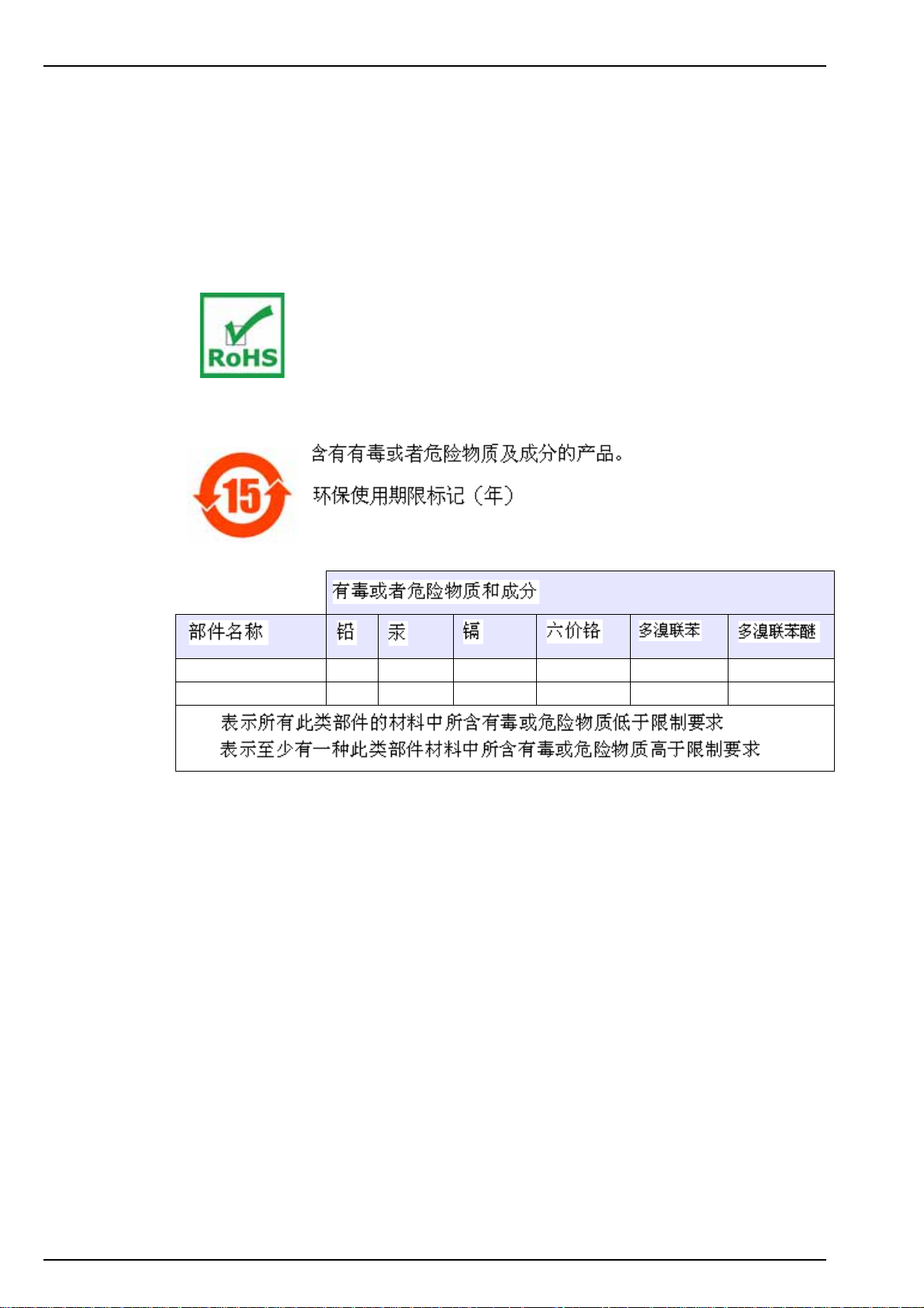
1.6 Restriction of hazardous substances (RoHS)
The European Union RoHS Directive and subsequent regulations introduced in member states
and other countries limits the use of six hazardous substances used in the manufacturing of
electrical and electronic equipment.
Currently, monitoring and control instruments do not fall within the scope of the RoHS Directive,
however Hach Lange has taken the decision to adopt the recommendations in the Directive as
the target for all future product design and component purchasing.
This product is compliant with the European Union RoHS Directive.
Note: The following only applies to exports of this product into the People’s Republic of China.
Connector socket X
Central tube X
O:
X:
8
Page 11
Section 2 Technical Specifications
Specifications are subject to change without notice.
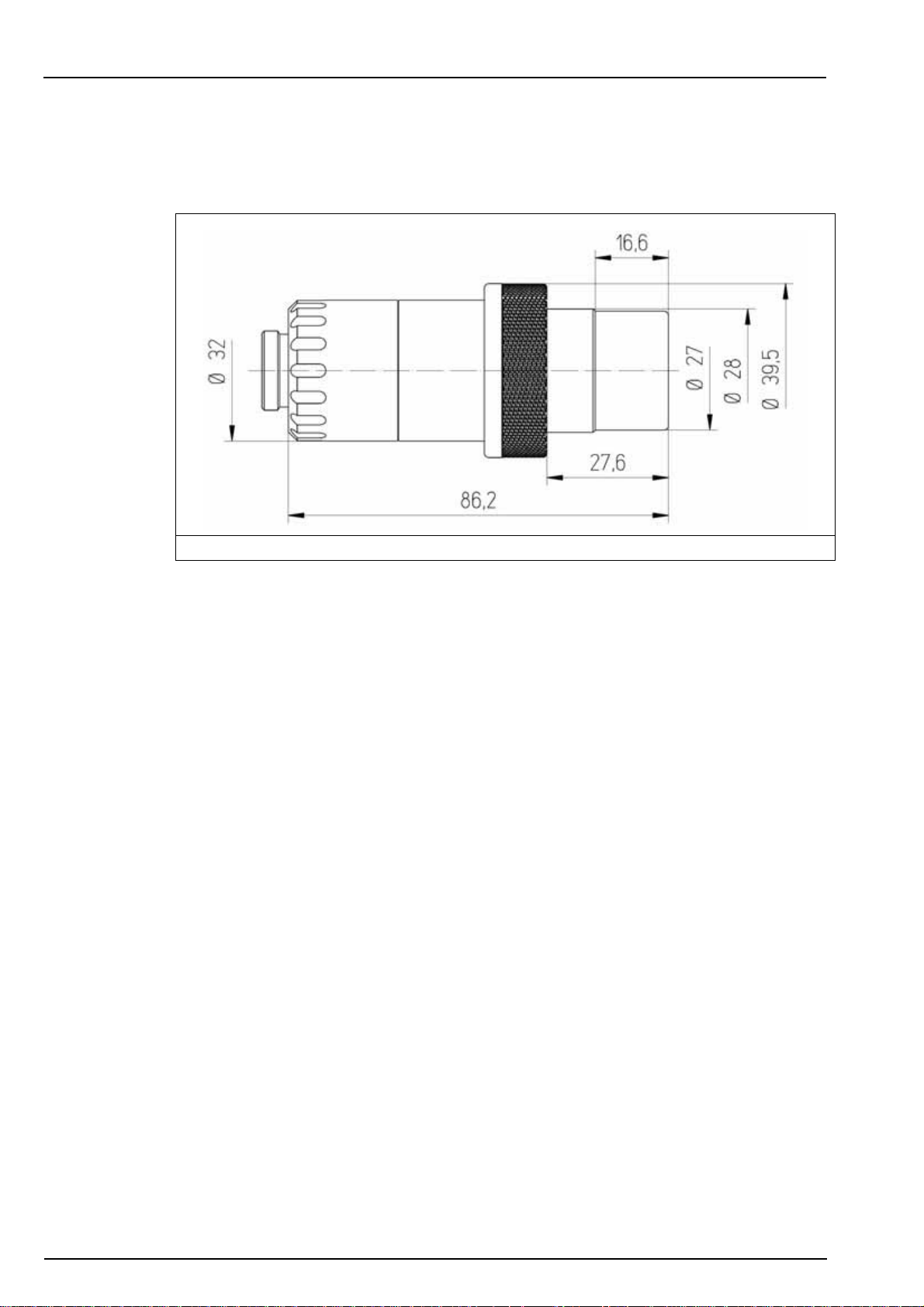
2.1 Sensor weight and dimensions
The sensor weight is approximately 300 grams.
Figure 1 Sensor dimensions
2.2 ORBISPHERE family of A1100 oxygen sensors
Model A1100 non-ATEX sensors
• Electrochemical oxygen sensor
• Stainless steel
• Maximum pressure 40 bar with default PPS collar (100 bar with stainless steel collar)
• Smart capability
Model A110E ATEX sensors
• Electrochemical oxygen sensor
• Ex II 1 G, Ex ia IIC T6
• Stainless steel or hastelloy
• Viton or kalrez o-rings
• Intrinsically safe
Note: Unlike the A1100 non-ATEX sensors, the intrinsically safe A110E ATEX sensors have no smart
capability to store calibration data. However, all A110E ATEX sensors have the ATEX conformity information
engraved on the sensor itself.
9
Page 12
Technical Specifications
2.3 Sensor configurations for standard applications
Table 1 Sensor configurations for standard applications
Application Sensor Membrane Cartridge Protection Cap
Beer with 3650 Portable A1100-S00
Beer in-line A1100-S00 2952A-A 33051-SG
Wort in-line A1100-S00 29552A-A 33051-S0
Wort with 3650 Portable and
special flow cell 32007W.xxx
Beverage
3624 Probrix A1100-S00 2952A-A 33051-SG
3625 Package analyzer A1100-S00 2956A-A or 2952A-A 33051-SP
De-aerated water A1100-S00 2956A-A or 2952A-A
On-line dissolved oxygen
traces in pure water
Dissolved oxygen traces
with 3655 Portable
(Power - Electronics)
Pure water applications
ATEX
A1100-S00 29552A-A 33051-S0
A1100-S00 2956A-A 33051-S0
A1100-S00 2956A-A 33051-S0
A110E-SVS
A110E-SKS 33051-SG
A110E-HVS 33051-H0
A110E-HKS 33051-H0
2958A-A (optimized response time)
2952A-A (optimized maintenance interval)
2956A-A or 29552A-A
33051-SP
33051-S0
33051-SG (if exposed to CIP)
33051-SG
Note: Non-ATEX sensors are delivered with two protection caps as standard, one with a grille (33051-SP)
and one without (33051-S0). A third protection cap (33051-SG) is available as an option. ATEX Sensors are
delivered with one protection cap as standard.
10
Page 13
Technical Specifications
2.4 Sensor membrane specifications
2.4.1 Oxygen sensors (Table 1)
Table 2 Membrane specifications - Ox yg e n se n so rs (1 )
2956A-A 2958A-A 29552A-A 2952A-A
In line wort,
Air/O
injection,
2
Sewage treatment
PTFE Tefzel
Recommended applications
Corrosion control,
De-aerated water
Beverage,
Lab. applications
Material PFA Tefzel
®
Thickness [µm] 25 12.5 50 25
Calibration gas Air Air Air Air / Pure O
Dissolved measurement range
Gaseous measurement range
0 ppb to
20 ppm
0 Pa to
50 kPa
The greater of
±1% of reading
or ± 0.1 ppb
Accuracy
or ± 1 ppb
or ± 0.25 Pa
1
Accuracy is ± 0.1 ppb for 410, 510, 362x, 360x and 3655 instruments
2
Accuracy is ± 1 ppb for 366x and 3650 instruments
Integrated radiation dose limit [rads] 2 x 10
Expected current in air
@ 1 bar 25°C [µA]
Expected current in pure O
consumption in O2 saturated
O
2
water at 25°C [µg/hour]
[µA] 132 47 31.4 27
2
26.4 9.4 6.3 5.4
40 14 9.4 8
1
,
2
,
4
0 ppb to
40 ppm
0 Pa to
100 kPa
The greater of
±1% of reading
or ± 1 ppb,
or ± 2 Pa
8
10
0 ppb to
80 ppm
0 Pa to
200 kPa
The greater of
±1% of reading
or ± 2 ppb,
or ± 5 Pa
N/A 10
Temp. compensation range – 5 to 60° C
Temp. measuring range – 5 to 100° C
Response time
Recommended min. liquid flow rate
[mL/min]
Recommended min. linear flow rate
[cm/sec]
Recommended gaseous flow rate
[L/min]
1
2
2
7.2 sec. 9.5 sec. 90 sec. 38 sec.
180 120 50 50
200 100 30 30
0.1 to 3
Corrosion control,
In line beverage,
De-aerated water
0 ppb to
80 ppm
0 Pa to
200 kPa
The greater of
±1% of reading
or ± 2 ppb,
or ± 5 Pa
8
®
2
11
Page 14

Technical Specifications
2.4.2 Oxygen sensors (Table 2)
Table 3 Membrane specifications - Oxygen sensors (2)
2935A-A 29521A-A 2995A-A
Recommended applications
Saturated to super
saturated levels
Material Halar
®
Saturated to super
saturated levels
®
Tefzel
In line hot wort
(up to 70°C)
Tedlar
Thickness [µm] 25 125 12.5
Calibration gas Air / Pure O
Dissolved measurement range
Gaseous measurement range
0 ppb to
400 ppm
0 Pa to
1000 kPa
The greater of
Accuracy
±1% of reading
or ± 10 ppb,
or ± 20 Pa
Integrated radiation dose limit [rads] N/A 10
Expected current in air
@ 1 bar 25°C [µA]
Expected current in pure O
consumption in O2 saturated
O
2
water at 25°C [µg/hour]
[µA] 4.7 3.8 0.9
2
0.9 0.7 0.2
1.4 1.3 0.3
Air / Pure O2 Pure O2
2
0 ppb to
400 ppm
0 Pa to
1000 kPa
The greater of
±1% of reading
or ± 10 ppb,
or ± 20 Pa
8
0 ppb to
2000 ppm
0 Pa to
5000 kPa
The greater of
±1% of reading
or ± 50 ppb,
or ± 100 Pa
10
Temp. compensation range – 5 to 60° C
Temp. measuring range – 5 to 100° C
Response time
Recommended min. liquid flow rate
1
2
[mL/min]
Recommended min. linear flow rate
2
[cm/sec]
Recommended gaseous flow rate
[L/min]
1
Response time at 25 °C for a 90% signal change
2
Liquid flow through an ORBISPHERE 32001 flow chamber, with protection cap and no grille
2.5 min. 18 min. 80 sec.
25 25 5
20 60 5
0.1 to 3
®
8
12
Page 15
Section 3 Introduction
3.1 What you have received
3.1.1 A1100 electrochemical sensor
The sensor may be delivered separately or as part of an ORBISPHERE system, depending on
the individual order.
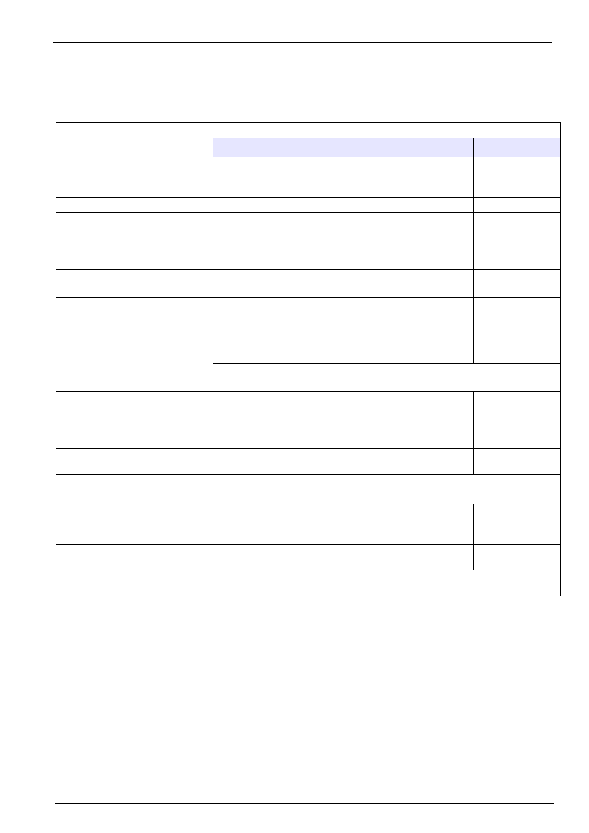
The sensor (as illustrated in Figure 2 above) will be delivered fitted with a plastic screw-on
storage cap to protect the sensor head. This is held in place with a plastic collar.
A plastic screw-on base is also provided to protect the connection socket, and which also
provides a suitable stand for the sensor during maintenance procedures, and when not in use.
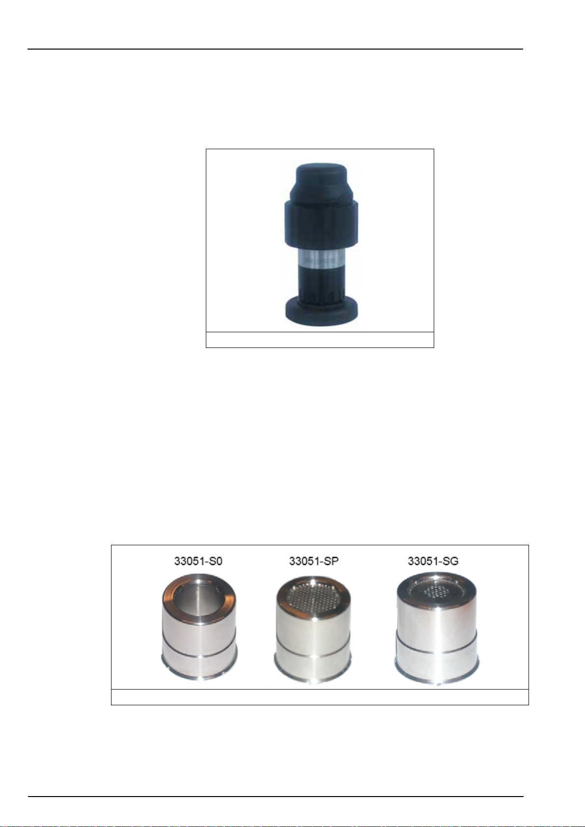
3.1.2 Protection caps
Non-ATEX sensors (A1100)
Two protection caps will be delivered with each sensor, one without a grille (part number
33051-S0) and one with a grille (part number 33051-SP).
A third protection cap (part number 33051-SG) is also available as an option and improves the
maintenance interval for beer or soft drinks process applications.
The three protection caps are illustrated below:
Figure 2 A1100 sensor with storage cap and base
Figure 3 Protection caps
ATEX sensors (A110E)
Only one protection cap will be delivered with each sensor (part number 33051-SG or
33051-H0).
13
Page 16

Introduction
3.1.3 Sensor recharge kit
A recharge kit (as illustrated in Figure 4 below) should have been ordered with the sensor as
this will be required to initially make the sensor operational. It is also required for sensor
cleaning and membrane replacement procedures.
Note: The recharge kit for oxygen has a blue sticker on the front of the box.
Figure 4 Sensor recharge kit
The kit contains:
• four recharge cartridges with pre-mounted membrane and electrolyte. The type of
membrane mounted in the cartridge will be specific to the kit ordered
• two anode cleaning tools
• a set of five cotton washers
• a set of five silicone discs (available in all 2956A-XXX recharge kits only)
• a set of replacement O-rings
• a set of Dacron
®
mesh patches.
14
Figure 5 Anode cleaning tool
The black anode cleaning tool (Figure 5) is used to clean the anode of any deposits or residue
that may have formed. It is doubled-ended so it can be used for two membrane replacement
processes, each end being used once.
Page 17

The cotton washers provide additional protection against the formation of deposits and residue
on the center electrode and anode, which prolongs the time period required between sensor
services.
The silicone discs are required for measurements in ultra-pure water or water containing
ammonia.
The Dacron
®
mesh patches provide protection to the membrane when using a protection cap
with grille.
For details of the part numbers for re-ordering, please refer to Recharge kits for A1100 and
A110E sensors on page 42.
3.2 Sensor components
The following illustration shows the assembled sensor with the storage cap and sensor collar
removed and the exploded view of the main sensor components. To remove the storage cap,
you will first have to unscrew and remove the sensor base.
Introduction
Figure 6 Sensor components
1 - Protection cap locking washer 4 - Cotton washer
2 - Protection cap (illustrated without grille) 5 - Silicone disc
3 - Cartridge containing electrolyte and membrane 6 - Sensor body
7 - Plastic base
Note: If a protection cap with grille is being used with the sensor, then a Dacron
between the protection cap and cartridge (components 2 and 3 in Figure 6 above).
®
mesh will be positioned
15
Page 18

Introduction
3.3 Basic principle of operation
In its simplest form, the electrochemical sensor consists of one center electrode (cathode) and
one counter electrode (anode) immersed in an electrolyte solution which is separated from the
gaseous or liquid sample by a gas permeable membrane. An electronic circuit is linked to the
anode and cathode. Through an applied voltage, current will flow between the anode and the
cathode.
A guard ring electrode surrounds the center electrode in order to reduce the influence of other
gases on the center electrode, and therefore improving analysis stability.
The sensor head is covered with a protection cap and, in some applications, a grille to protect
the membrane. Materials used for the components of the sensors differ with the application.
Gas penetrating through the membrane into the cell dissolves in the electrolyte. It undergoes a
reaction at the cathode, causing a measurable electric current to flow. This current is
proportional to the amount of gas entering the cell, which in turn is proportional to the partial
pressure of gas in the sample outside the cell.
The result is shown as gas concentration, which can then be displayed with a choice of several
measuring units, according to instrument setup.
The sensor also includes “smart sensor technology”, implemented using an RS485 interface.
The sensor electronics perform four functions:
• Apply constant voltage to the anode
• Measure the current flowing through the sensor
• Compensate for temperature variation in the gaseous or liquid sample
• Convert the cell’s electric current into an analog signal for sensor output
16
Page 19

Section 4 Installation
4.1 Sensor preparation
Your A1100 electrochemical sensor has been thoroughly cleaned and tested at the factory
before shipment. It has been shipped with a cartridge containing a membrane and electrolyte
pre-installed to protect the sensor head. This cartridge must be removed and replaced with a
new one prior to first use to make it fully operational. The new cartridge is included in the sensor
recharge kit (see additional details in Sensor recharge kit on page 14).
Non-ATEX sensors (A1100)
The sensor has been delivered with two protection caps, one with a grille and one without.
Ensure you use the correct protection cap for your application (see Table 1 on page 10 for
additional information).
ATEX sensors (A110E)
The sensor has been delivered with a single protection cap.
The following instructions detail the steps required to make the sensor operational. Should you
have any questions, your Hach Lange representative will be pleased to help.
CAUTION
Avoid all eye and skin contact with the electrolyte in the sensor and replacement
cartridge as it is corrosive and can cause burning. If eyes or skin come into cont act with
electrolyte, rinse immediately with water. In addition, the electrolyte can permanently
stain clothing so exercise care in han d li ng . It is highly recommended to wear protective
gloves and glasses during this process.
Note: It is advisable to perform this procedure with the plastic sensor base installed so as to avoid any
damage to the connection socket and also to provide a suitable stand for the sensor when required.
1. Hold the main body of the sensor and
unscrew the protection cap locking washer
by turning counter-clockwise. Remove it from
the sensor and put to one side.
2. Pull/twist off the protection cap and put to
one side.
17
Page 20

Installation
3. Hold the sensor with the membrane facing
down to avoid spilling any electrolyte, then
carefully unscrew the shipment cartridge.
Drain the old electrolyte into a sink and flush
away. Discard the shipment cartridge and
membrane.
4. Remove the cotton washer from the top of
the anode and discard.
5. Rinse the sensor head under a tap for 15
seconds, aiming the jet of water directly onto
the sensor head.
6. Do not dry the center electrode area, as the
gap between cathode and guard should be
left filled with water.
18
Page 21

Note: During this step, it is very important to ensure
your finger does not come into contact with the
cathode (golden surface) as it could leave greasy
deposits on the surface.
7. Take a silicone disc from the recharge kit,
hold it between thumb and forefinger and
position it on top of the anode.
Installation
Note: As in the previous step, it is very important to
ensure your finger does not come into contact with the
cathode (golden surface) as it could leave greasy
deposits on the surface.
8. Take a new cotton washer from the recharge
kit, hold it between thumb and forefinger and
position it on top of the silicone disc.
9. Place the recharge cartridge container on a
flat work surface and, keeping the container
upright to avoid spilling any of the electrolyte
inside, carefully unscrew the top.
10. Remove the packing component from the
center of the cartridge, making sure that the
O-ring on top of the cartridge remains in
place. If it comes away then replace it before
continuing.
11. If there are any visible bubbles in the
electrolyte, remove them using a stirring
motion with the packing component.
19
Page 22

Installation
12. Hold the container steady between thumb
and forefinger of one hand.
13. Lower the sensor into the container until the
top of the anode is covered with electrolyte.
14. Leave for a few seconds to ensure the cotton
washer has fully absorbed some of the
electrolyte and that it is no longer dry.
15. Gently screw the sensor clockwise into the
replacement cartridge, applying minimum
pressure to avoid any damage to the screw
threads.
16. Continue turning until the cartridge is
attached to the sensor, and the sensor is
automatically released from the container.
17. The empty container, the screw top and
packing component can be discarded.
Note: It is normal that some of the electrolyte will
overflow from the replacement cartridge and into the
plastic container.
20
Page 23

18. Rinse the sensor under a tap for about 5
seconds to remove any excess electrolyte,
then gently wipe with a soft tissue to ensure
all parts are completely dry.
19. Drain the overflow electrolyte from the
container into a sink and flush away.
20. Discard the used container.
Installation
21. If not using a protection cap with grille
proceed to step 24. Otherwise take a new
Dacron
recharge kit.
22. Place the mesh in the center of the
protection cap. It is very important that the
mesh is in the center of the protection cap
and covering the entire grille.
23. Lower the sensor onto the protection cap
making sure not to disturb the mesh.
24. Push the protection cap firmly into place,
making sure one of the four slots in the
protection cap fits over the small locking pin
(highlighted right). If it is necessary to turn
the protection cap to fit over the locking pin,
ensure you only turn it clockwise to avoid
unscrewing the cartridge.
®
mesh from the box of O-rings in the
21
Page 24

Installation
25. Finally, screw the protection cap locking
washer back into place in a clockwise
motion, and tighten finger tight.
4.2 Sensor installation
4.2.1 Sensor positioning information
Unless the sensor is part of the ORBISPHERE equipment that includes it, the sensor must be
installed in an ORBISPHERE socket or flow chamber, that allows contact with the sample fluid
to be analyzed.
The sensor and measuring instrument are connected by a cable and two 10-pin connectors.
The standard sensor cable length is 3 meters though extension cables of up to 1000 meters are
available. However, smart sensor technology is only available with distances of up to a
maximum of 750 meters.
Note: If the model 28117 pressure sensor is used, the maximum cable length is 50 meters.
Ensure that the sensor will be mounted:
• perpendicular to the pipe
• horizontal
• on a horizontal pipe section (or on flow-ascending vertical pipe)
• min. 15 meters away from pump's discharge side
• in a place where the sample flow is stable and rapid, and as far as possible from:
• valves
• pipe bends
• the suction side of any pumps
• a CO
Note: There may be situations where not all the above conditions can be met. If this is the case, or you
have any concerns, please consult your Hach Lange representative to appraise the situation and define the
best applicable solution.
injection system or similar
2
22
Page 25

4.2.2 Sensor insertion
Note: Check that the small O-ring at the bottom of the flow chamber is present during removal and
installation of the sensor, as it may stick to the sensor head and fall.
• Insert the sensor straight into the flow chamber or socket.
• Hand tighten the attaching collar.
• Connect the sensor cable.
• Check for leaks; replace O-rings if product leaks are visible.
Micro Volume Flow Chambers:
Installation
Note: Do not twist the sensor when inserting it into a micro volume flow chamber. This rotation may twist the
membrane holding ring, thus changing the membrane position. This can modify the membrane measuring
conditions, and affect measurement precision.
4.2.3 Sensor removal
• Shut off the sample flow and drain the sampling circuit of liquid or gas.
• Remove the sensor cable connected at the sensor end.
• Hold the sensor body in one hand to avoid rotation and unscrew the collar with the other
hand.
• Pull the sensor straight out of the socket or flow chamber.
• Check that both O-rings remain in place inside the flow chambers.
• Install sensor storage cap and sensor base (to protect the connection).
Figure 7 Sensor insertion
23
Page 26

Installation
4.3 Mounting accessories
4.3.1 External pressure sensor
The system can be fitted with an external pressure sensor. This enables a measurement of
fraction of gas under variable pressure conditions during gas phase measurement.
Note: Do NOT exceed the pressure range of the sensor. This would permanently deform the sensor
membrane, thus delivering incorrect pressure values in the future.
The external sensor connects to the ORBISPHERE measuring equipment with a 1 meter cable
and a 4 pin connector (an optional extension cable can be used, but total length should not
exceed 50 m.).
Two models are available, depending on application:
• 28117 Pressure sensor 0 - 5 bar absolute
• 28117C Pressure sensor 0 - 1 bar absolute
The external pressure sensor can be installed in the 32002.xxx multi parameter flow chamber. It
is held in place by a blue threaded collar. Tightness is assured by the O-ring on the sensor seat.
4.3.2 Weld-on stainless steel socket
The 29501 weld-on sensor socket can be used to install a sensor into a stainless steel pipe
(min.Ø 50 mm or 2”). When welding the socket to the pipe, check that setback between the
pipe’s inner diameter and the sensor tip does not exceed 4 mm (see diagram).
Figure 8 Weld-on sensor socket
24
Note: Be sure to remove the two O-rings from the socket before welding and leave the sensor’s stainless
steel cap screwed on during welding to prevent thread distortion.
Page 27

Recommendation:
To facilitate sensor removal and installation, we suggest installing the socket in a location where
the liquid can be drained quickly and easily. By creating a one meter long piece of pipe (shown
below) with shut off valves at both ends, just a small volume of liquid needs to be drained to
enable sensor removal. Also, a precise sensor and socket installation can be performed in the
workshop, and this assembly can be placed in the production line with minimal down time.
4.3.3 The 32003 insertion/extraction valve
Installation
Figure 9 Installation in-line
The ORBISPHERE 32003 insertion/extraction valve (illustrated below) allows for sensor
removal and installation without having to drain the fluid in the line. It can withstand a pressure
of up to 20 bars, with the sensor in place or not.
Sensor insertion is made by inserting the sensor into the housing and tightening the retaining
collar until it stops. As the retaining collar is tightened, the valve will open to allow the sample to
flow past the sensor head. Remove the sensor by unscrewing the collar and pulling the sensor
out. As the collar is unscrewed, the valve will automatically close to avoid any sample spillage.
Figure 10 ORBISPHERE model 32003 insertion/extraction valve
The diagram above right, shows the sensor in a sample line with the valve open allowing the
sample to run past the sensor head.
25
Page 28

Installation
4.3.4 The 33095 sensor housing
The ORBISPHERE 33095 sensor housing is also available for use with the A1100 sensor but
requires that the sample flow be turned off prior to insertion or removal of the sensor.
Sensor insertion is made by inserting the sensor into the housing and tightening the retaining
collar until it stops. Removal is made by unscrewing the collar and pulling the sensor out. Be
sure that the sample flow has been turned off before inserting or removing the sensor.
4.3.5 Tuchenhagen Varivent® in-line access unit
The following illustration shows the Tuchenhagen Varivent® In-Line Access Unit.
Figure 11 Tuchenhagen Varivent® in-line access unit
Purchasing a Tuchenhagen Varivent® in-line access unit, or an equivalent fitting with a 68 mm
flange diameter from the fitting manufacturer, is required to make use of the ORBISPHERE
model 32003 sensor housing device detailed above.
4.3.6 ORBISPHERE flow chambers
The ORBISPHERE 32001.xxx flow chambers are used to draw liquid and gaseous samples
past the sensor. They are available in several materials, depending on the application.
They connect to 6-mm or ¼" stainless steel tubing by means of two Swagelok™ fittings. If
necessary, copper or plastic tubing with low permeability can be substituted. Stainless steel
tubing is normally enough to hold the assembly in place, but for a more stable installation, a
large U-bolt can be used to mount the flow chamber to a support.
Dimensions of sensor and flow chamber assembly :
• Width: 50 mm
• Height: 210 mm
(add 100 mm for connection length)
26
Page 29

Table 4 Flow Chamber Orientation
Sample Orientation of flow chamber
Vertically, with connections down and
Gaseous or
liquid media
sensor up
- Center connection is the inlet
- Outer connection is the outlet
Installation
Gaseous media,
with occasional
liquid or vapor
Horizontally, to allow for drainage
- Center connection (inlet) must be up
- Outer connection (outlet) must be down
The connection diagram below is a recommended installation that allows for measuring and
calibrating without having to disconnect a line manually. "A" and "B" represent 3-way valves.
For measuring, calibration gas inlets and outlets are shut off. During calibration, the flow is
reversed to drive the remaining sample out. The calibration gas enters at the "sample out" port
and exits at the "sample in" port, as shown.
Figure 12 Flow chamber connections
27
Page 30

Installation
4.3.7 Multi-parameter flow chamber
Note: Suitable only for gaseous media.
The ORBISPHERE 32002.xxx multi parameter flow chamber can accommodate one or two
sensors and one sample pressure sensor. If only one gas sensor is used, the unused socket is
plugged with the stainless steel plugs provided (model 28123). The flow chamber is connected
to 6 mm or ¼" stainless steel tubing by two Swagelok™ fittings. If necessary, copper or plastic
tubing with a very low permeability can be substituted.
The flow chamber should be mounted in such a way that the sample outlet port is located at the
lowest point to allow condensation to escape with the outgoing gas. Attach the flow chamber to
a vertical support with the screws supplied. The pressure sensor must be on top.
Note: A user manufactured spacer (~15 mm thick) may be used between the flow chamber and support for
improved access for sensor removal.
28
Figure 13 32002.xxx Multi parameter flow chamber
Shown here with:
• gas sensor (right),
• pressure sensor (center),
• optional second sensor (left)
Page 31

Section 5 Maintenance and Troubleshooting
5.1 Maintenance
5.1.1 Maintenance schedule
The following table shows the recommended schedule for membrane replacement. The table
should only be used as a guideline, as maintenance intervals will vary depending on a number
of different parameters (e.g. water chemistry, CIP frequency, oxygen levels, sample
temperature, etc.).
Table 5 Maintenance schedule
Application Membrane type
Water applications (> 10ppb) 2956A Every 3 to 6 months
Pure water applications (power and electronics < 10 ppb) 2956A Every 3 to 6 months
Beer in-line 2952A Every 3 to 6 months
Wort in-line 29552A or 2995A Every 1 or 2 months
Portable or lab applications 2952A or 2958A Every 3 to 6 months
5.1.2 Prerequisites for sensor maintenance
The following table lists the prerequisites for a sensor maintenance:
Table 6 Prerequisites for sensor maintenance
Part No. Description
2959 Electrolyte for oxygen sensors, 50 ml. bottle.
29781 Cathode polishing powder (part no.29331) and cloth (part no. 2934).
32301 Electrochemical cleaning and regeneration center (see below)
40089 Tweezers, for maintenance kits
DG33303 Cleaning tool for sensor polishing
Important Note: If the sensor is being used in a high level hydrogen sample, this cleaning and
regeneration center is not required. In all other cases it is a prerequisite.
Membrane
replacement
The ORBISPHERE 32301 (illustrated below) is a very efficient cleaning and regeneration tool
for electrochemical sensors. This tool reverses the electrochemical process that is taking place
in the sensor cell during normal operation. This removes oxidation and at the same time
regenerates the surface of the electrodes. In addition, the regeneration center offers a continuity
tester for checking the sensor electronics.
29
Page 32

Maintenance and Troubleshooting
5.1.3 Membrane replacement and sensor head cleaning
A sensor recharge kit is required as it contains all the required components necessary for this
membrane replacement and sensor head cleaning process (see details in Sensor recharge kit
on page 14).
CAUTION
Avoid all eye and skin contact with the electrolyte in the sensor and replacement
cartridge as it is corrosive and can cause burning. If eyes or skin come into cont act with
electrolyte, rinse immediately with water. In addition, the electrolyte can permanently
stain clothing so exercise care in han d li ng . It is highly recommended to wear protective
gloves and glasses during this process.
Note: It is advisable to perform this procedure with the plastic sensor base installed so as to avoid any
damage to the connection socket and also to provide a suitable stand for the sensor when required.
1. Hold the main body of the sensor and
unscrew the protection cap locking washer
by turning counter-clockwise. Remove it from
the sensor and put to one side.
2. Pull/twist off the protection cap and put to
one side. If you are using a protection cap
with a grille, then remove the Dacron
from inside the cap and discard it.
®
mesh
30
Page 33

3. Hold the sensor with the membrane facing
down to avoid spilling any electrolyte, then
carefully unscrew the old cartridge. Drain the
old electrolyte into a sink and flush away.
Discard the old cartridge and membrane.
4. Remove the cotton washer and silicone disc
from the top of the anode and discard.
Maintenance and Troubleshooting
5. Rinse the sensor head under a tap for 15
seconds to remove any remaining electrolyte
and shake dry.
6. With a soft tissue gently clean around the
guard area (indicated right) and then wipe off
any excess moisture from the sensor to
ensure all parts are completely dry.
7. Repeat this rinse and dry process with the
protection cap.
8. Clean the anode using the cleaning tool
supplied.
9. Place the tool over the sensor head.
31
Page 34

Maintenance and Troubleshooting
10. Clean by rotating the cleaning tool over the
sensor head for a few seconds, in a
clockwise direction only.
11. Remove the tool and tap it face down on a
flat work surface to remove any powdery
deposit.
12. Check the sensor to ensure that all deposits
have been removed from the anode. If not,
repeat steps 10. and 11. until the anode
regains its bright silver appearance.
13. Rinse the sensor head under a tap for 15
seconds, aiming the jet of water directly onto
the sensor head.
14. Do not dry the center electrode area, as the
gap between cathode and guard should be
left filled with water.
15. Spread a little of the polishing powder
(29331) onto the clean polishing cloth (2934),
and add a few drops of water to form a grey,
milky liquid.
32
Page 35

16. Screw the polishing tool (DG33303) onto the
top of the sensor.
Maintenance and Troubleshooting
17. Polish the electrodes by moving the sensor
face in a circular direction against the liquid
in the polishing cloth for about 30 seconds.
18. Remove the polishing tool from the sensor.
19. Remove any polish deposits by rinsing the
sensor head under a tap for 30 seconds,
aiming the jet of water directly onto the
sensor head.
Important Note: If the sensor is used in high
level hydrogen sample, do not perform the
following steps but continue at step 29.
33
Page 36

Maintenance and Troubleshooting
20. Remove the plastic base from the bottom of
the sensor and connect the sensor to the
sensor cleaning and regeneration center
(32301).
21. Push the cleaning tool over the sensor head.
22. Pour enough electrolyte (2959) into the
cleaning tool until it completely covers all the
electrodes.
23. On the sensor cleaning and regeneration
center, turn the knob to the Anode position
and press the TIMER switch. A red warning
light will come on and remain on for 60
seconds while cleaning takes place.
24. At the end of the 60 second cleaning
process, check for an abundant stream of
bubbles should rise from the anode.If this
does not happen, press TIMER again.
Note: The development of bubbles is a sure sign of a
clean electrode.
25. On the sensor cleaning and regeneration
center, turn the knob to the Guard position
and press the TIMER switch. Again, watch
for the formation of bubbles and repeat the
cleaning process if necessary.
34
Page 37

26. On the sensor cleaning and regeneration
center, turn the knob to the Cathode position
and press the TIMER switch. Again, watch
for the formation of bubbles and repeat the
cleaning process if necessary.
27. When cleaning is complete, unplug the
sensor from the cleaning center and re-install
the plastic sensor base for the rest of the
procedure.
Maintenance and Troubleshooting
28. Remove any remaining electrolyte by rinsing
the sensor head under a tap for 60 seconds,
aiming the jet of water directly onto the
sensor head.
29. With the help of a pair of tweezers, remove
the old O-ring from the sensor body.
30. Replace the O-ring with a new one from the
recharge kit.
35
Page 38

Maintenance and Troubleshooting
Note: During this step, it is very important to ensure
your finger does not come into contact with the
cathode (golden surface) as it could leave greasy
deposits on the surface.
31. Take a silicone disc from the recharge kit,
hold it between thumb and forefinger and
position it on top of the anode.
Note: As in the previous step, it is very important to
ensure your finger does not come into contact with the
cathode (golden surface) as it could leave greasy
deposits on the surface.
32. Take a new cotton washer from the recharge
kit. Hold it between thumb and forefinger and
position it on top of the silicone disc.
33. Place the recharge cartridge container on a
flat work surface and, keeping the container
upright to avoid spilling any of the electrolyte
inside, carefully unscrew the top.
34. Remove the packing component from the
center of the cartridge, and make sure that
the O-ring remains in place on top of the
cartridge. If it comes away then replace it
before continuing.
35. If there are any visible bubbles in the
electrolyte, remove them using a stirring
motion with the packing component.
36
Page 39

36. Hold the container steady between thumb
and forefinger of one hand.
37. Lower the sensor into the container until the
top of the anode is covered with electrolyte.
38. Leave for a few seconds to ensure the cotton
washer has fully absorbed some of the
electrolyte and that it is no longer dry.
39. Gently screw the sensor clockwise into the
replacement cartridge, applying minimum
pressure to avoid any damage to the screw
threads.
Maintenance and Troubleshooting
40. Continue turning until the cartridge is
attached to the sensor, and the sensor is
automatically released from the container.
41. The empty container, the screw top and
packing component can be discarded.
Note: It is normal that some of the electrolyte will
overflow from the replacement cartridge and into the
plastic container.
37
Page 40

Maintenance and Troubleshooting
42. Rinse the sensor under a tap for about 5
seconds to remove any excess electrolyte,
then gently wipe with a soft tissue to ensure
all parts are completely dry.
43. Drain the overflow electrolyte from the
container into a sink and flush away.
44. Discard the used container.
45. If not using a protection cap with grille
proceed to step 48. Otherwise, take a new
Dacron
recharge kit.
46. Place the mesh in the center of the
protection cap. It is very important that the
mesh is in the center of the protection cap
and covering the entire grille (as illustrated
right).
47. Lower the sensor onto the protection cap
making sure not to disturb the mesh.
®
mesh from the box of O-rings in the
38
Page 41

48. Push the protection cap firmly into place,
making sure one of the four slots in the
protection cap fits over the small locking pin
(highlighted right). If it is necessary to turn
the protection cap to fit over the locking pin,
ensure you only turn it clockwise to avoid
unscrewing the cartridge.
Maintenance and Troubleshooting
49. Finally, screw the protection cap locking
washer back into place in a clockwise
motion, and tighten finger tight.
39
Page 42

Maintenance and Troubleshooting
5.2 Troubleshooting
Problem Probable cause Possible solution
Table 7 Troubleshooting
Sensor won't calibrate, even after
cleaning and/or membrane change.
"0000" O2 levels displayed.
Shorter than expected sensor operation
in relatively high dissolved O
concentration.
Unexpected or inaccurate dissolved O
readings.
Calibration is out of specification or
response time is too slow.
2
2
Instrument internal barometric pressure
sensor needs calibration.
Wet membrane interface. Wipe dry with a tissue and recalibrate.
S insensitivity" option enabled.
"H
2
Wrong reading scale "XXXX" selected
for display unit.
High O
deposits more quickly.
Air leak on product sample line.
High residual current.
Sensor incorrectly setup.
Temperature measurement incorrect.
Barometric pressure incorrect.
Cartridge incorrectly assembled on
sensor.
Sensor electrodes are dirty.
Sensor maintenance is required.
concentrations generate
2
Calibrate using a certified barometer. Do
not correct for sea level !
Disable from the menu on the
measuring instrument.
Change reading scale by selecting
"X.XXX, XX.XX or XXX.X" on the
instrument.
Install a less permeable membrane.
Turn off the analyzer when sensor is not
in a low O
Set flow rate to 100 ml/min. Wait until
stable, then slowly double the flow rate.
The stable value of dissolved O2 reading
must be the same as before. A variation
related to flow rate is a clear sign of an
air leak in the line.
Place sensor in de-aerated sample and
wait for low reading.
Check concentration against low
measurement limit (see tables in Sensor
membrane specifications on page 11).
If concentration is significantly higher
than low limit, try replacing the
membrane.
Check the sensor parameters on the
instrument.
Recalibrate the sensor.
Control the temperature with an external
reference.
Recalibrate the sensor.
Calibrate the barometric pressure
sensor using the instrument.
Recalibrate the sensor.
Verify the cartridge assembly is firmly
screwed onto the sensor and that the
membrane is tight.
Recalibrate the sensor.
Clean the sensor using the
ORBISPHERE 32301 cleaning and
regeneration center as explained in this
section.
Recalibrate the sensor.
Replace the membrane by installing a
new sensor cartridge as explained in
this section.
Recalibrate the sensor.
concentration.
2
40
Page 43

Section 6 Accessories and Spare Parts
6.1 Accessories
Table 8 Sensor accessories
Part N° Description
28117 Pressure sensor, 0-5 bar absolute
28117.C Pressure sensor, 0-1 bar absolute
6.2 Flow chambers and installation devices
Table 9 Flow chambers and installation devices
Part N° Description
29501.0 Sensor socket for welding to SS pipe, with EPDM O-ring
29501.1 Sensor socket for welding to SS pipe, with Viton O-ring
29508 Multi parameter flow chamber for headspace piercing device
32001.010 Flow chamber in stainless steel (316) with 6 mm fittings. Supplied with EPDM O-rings.
32001.011 Flow chamber in stainless steel (316) with ¼" fittings. Supplied with EPDM O-rings.
32001.012 Flow chamber in stainless steel (316) with 8 mm fittings. Supplied with EPDM O-rings.
32001.030 Flow chamber in Delrin with 6 mm fittings. Supplied with EPDM O-rings.
32001.031 Flow chamber in Delrin with ¼" fittings. Supplied with EPDM O-rings.
32001.040 Flow chamber in Hastelloy with 6 mm fittings. Supplied with EPDM O-rings.
32001.041 Flow chamber in Hastelloy with ¼" fittings. Supplied with EPDM O-rings.
32001.070 Flow chamber in Monel with 6 mm fittings. Supplied with EPDM O-rings.
32001.071 Flow chamber in Monel with ¼" fittings. Supplied with EPDM O-rings.
32001.110 Flow chamber in stainless steel (316) with 6 mm fittings. Supplied with Viton O-rings.
32001.111 Flow chamber in stainless steel (316) with ¼" fittings. Supplied with Viton O-rings.
32001.140 Flow chamber in Hastelloy with 6 mm fittings. Supplied with Viton O-rings.
32001.141 Flow chamber in Hastelloy with ¼" fittings. Supplied with Viton O-rings.
32001.151 Flow chamber in titanium with ¼" fittings (6 mm fittings not available in titanium) Supplied with Viton O-rings.
32001.170 Flow chamber in Monel with 6 mm fittings. Supplied with Viton O-rings.
32001.171 Flow chamber in Monel with ¼" fittings. Supplied with Viton O-rings.
32001.181 Flow chamber in Kynar with ¼" fittings. Supplied with Viton O-rings.
32001.191 Flow chamber in PTFE with ¼" fittings. Supplied with Viton O-rings.
32002.010 Multi parameter flow chamber in stainless steel with 6 mm fittings. Supplied with EPDM O-rings.
32002.011 Multi parameter flow chamber in stainless steel with ¼" fittings. Supplied with EPDM O-rings.
32003 ProAcc sensor insertion device ; for use with Tuchenhagen adapter
32006 Flow chamber in stainless steel (316) for use with for model 28117 and 28117.C pressure sensors.
32007D Flow chamber in Delrin for the 3655 portable instrument, with one meter of tubing.
32007F
32007W.030
32007W.031
32009 Flow chamber in acrylic with 1/8" Swagelok fittings for small volume liquid phase measurements.
32011
32017 Flow chamber used with 29981 Pharmapack. Must be ordered separately.
Flow chamber in Delrin for the 3650 portable instrument. Includes check valve, 1 meter of inlet tubing, quarter
turn flow valve, and outlet metal U-tube (6mm outside diameter).
Flow chamber in Delrin with 6 mm stainless steel Swagelok fittings for use with liquids with suspended
particles. Supplied with EPDM O-rings.
Flow chamber in Delrin with ¼" stainless steel Swagelok fittings for use with liquids with suspended particles.
Supplied with EPDM O-rings.
Flow chamber in acrylic with 1/8" Swagelok fittings for small volume liquid phase measurements, with port for
32562 external temperature sensor.
41
Page 44

Accessories and Spare Parts
6.3 Sensor spare parts
Table 10 Sensor spare parts
Part N° Description
A1100-S00
A110E-SVS A110E oxygen sensor, ATEX, stainless steel, viton o-rings, cap with grille
A110E-SKS A110E oxygen sensor, ATEX, stainless steel, kalrez o-rings, cap with grille
A110E-HVS A110E oxygen sensor, ATEX, hastelloy, viton o-rings, cap without grille
A110E-HKS A110E oxygen sensor, ATEX, hastelloy, kalrez o-rings, cap without grille
28104 Stainless steel sensor collar
28105 PPS sensor collar
28129 Delrin storage cap (sensor storage cap)
32205 Sensor support (base) for 31xxx sensors
33051-S0 Stainless steel 28mm cap for ORBISPHERE A1100 family EC sensors (without grille)
33051-SG
33051-SP
33051-H0 Hastelloy 28mm cap without grille for ORBISPHERE A110E ATEX sensors.
33052 Kit of 5 dacron mesh for protection cap with grille model 33051-SG or 33051-SP
A1100 oxygen sensor, non-ATEX, stainless steel, maximum pressure 40 bar with default PPS collar (100 bar
with 28104 stainless steel collar), with smart capability
Stainless steel 28mm cap with grille for ORBISPHERE A1100 family EC sensors. For use in beer or soft-drinks
processes and ATEX configurations.
Stainless steel 28mm cap with grille for ORBISPHERE A1100 family EC sensors. For use with 3625 package
analyzer and 3650 instrument when measuring beer or soft-drinks.
6.4 Recharge kits for A1100 and A110E sensors
Table 11 Recharge kits for A1100 sensors
Part N° Description
2935A-A
29521A-A
2952A-A
29552A-A
2956A-A
2956A-A05
2958A-A
2995A-A
2956A-AV
2956A-AK
29552A-AV
29552A-AK
Recharge kit of 4 pre-filled cartridges with premounted 2935A membranes for A1xxx oxygen sensors.
Includes o-rings, cotton washers and cleaning tools
Recharge kit of 4 pre-filled cartridges with premounted 29521A membranes for A1xxx oxygen sensors.
Includes o-rings, cotton washers and cleaning tools
Recharge kit of 4 pre-filled cartridges with premounted 2952A membranes for A1xxx oxygen sensors.
Includes o-rings, cotton washers and cleaning tools
Recharge kit of 4 pre-filled cartridges with premounted 29552A membranes for A1xxx oxygen sensors.
Includes o-rings, cotton washers and cleaning tools
Recharge kit of 4 pre-filled cartridges with premounted 2956A membranes for A1xxx oxygen sensors.
Includes o-rings, cotton washers, silicone discs and cleaning tools
Recharge kit of 4 pre-filled cartridges with premounted 2956A membranes for A1xxx oxygen sensors.
Includes o-rings, cotton washers, silicone discs and cleaning tools. Special low concentrate electrolyte
Recharge kit of 4 pre-filled cartridges with premounted 2958A membranes for A1xxx oxygen sensors.
Includes o-rings, cotton washers and cleaning tools
Recharge kit of 4 pre-filled cartridges with premounted 2995A membranes for A1xxx oxygen sensors.
Includes o-rings, cotton washers and cleaning tools
Recharge kit of 4 pre-filled cartridges with premounted 2956A membranes for A1xxx oxygen sensors.
Includes viton o-rings, cotton washers, silicone discs and cleaning tools
Recharge kit of 4 pre-filled cartridges with premounted 2956A membranes for A1xxx oxygen sensors.
Includes kalrez o-rings, cotton washers, silicone discs and cleaning tools
Recharge kit of 4 pre-filled cartridges with premounted 29552A membranes for A1xxx oxygen sensors.
Includes viton o-rings, cotton washers and cleaning tools
Recharge kit of 4 pre-filled cartridges with premounted 29552A membranes for A1xxx oxygen sensors.
Includes kalrez o-rings, cotton washers and cleaning tools
42
Page 45

Accessories and Spare Parts
6.5 Other spare parts
Table 12 Other spare parts
Part N° Description
28093.0 EPDM O-rings for pressure sensor 28117.X. 18.78 x 1.78mm. (5 pieces)
28093.2 Kalrez O-ring for pressure sensor 28117.X. 18.78 x 1.78mm. (1 piece)
28093.4 Nitril O-rings for pressure sensor 28117.X. 18.78 x 1.78mm. (5 pieces)
29006.0
29006.1
29006.2
29006.4
29037 Regeneration cell for 32301, electrochemical sensor cleaning and regeneration unit
2959 Electrolyte for oxygen sensors, 50 ml. bottle.
29781 Cathode polishing powder (part no.29331) and cloth (part no. 2934).
32301 Electrochemical cleaning and regeneration center
40089 Tweezers, for maintenance kits
DG33303 Cleaning tool for sensor polishing
EPDM O-ring set for standard flow chambers (32001, 32002, 32007, 32009) and 29501 sensor socket.
(34x2mm & 28x2 mm).
Viton O-ring set for standard flow chambers (32001, 32002, 32007, 32009) and 29501 sensor socket. (34x2
mm & 28x2 mm).
Kalrez O-ring set for standard flow chambers (32001, 32002, 32007, 32009) and 29501 sensor socket. (34x2
mm & 28x2 mm).
Nitril O-ring set for standard flow chambers (32001, 32002, 32007, 32009) and 29501 sensor socket. (34 x 2
mm & 28 x 2 mm).
43
Page 46

Accessories and Spare Parts
44
Page 47

Page 48

 Loading...