

Page 1

Document Number DG3650EX-MAN/E
ORBISPHERE Model 3650 Atex
USER MANUAL
August 2013, Revision I
Page 2

Page 3

Table of Contents
Section 1 General Information.........................................................................................................3
1.1 Disclaimer .................................................................................................................................... 3
1.2 Contact information...................................................................................................................... 3
1.3 Safety information ........................................................................................................................ 3
1.3.1 Use of hazard information................................................................................................... 3
1.3.2 Service and repairs .............................................................................................................3
1.3.3 Safety recommendations .................................................................................................... 4
1.3.4 Interface box (model 29122) ...............................................................................................4
1.3.5 Precautionary labels............................................................................................................5
1.4 Intrinsically safe conformity.......................................................................................................... 6
1.5 Product recycling information.......................................................................................................7
1.6 Product disposal .......................................................................................................................... 9
1.7 Restriction of hazardous substances (RoHS) ............................................................................10
Section 2 Specifications and Certifications ............................................................................... 11
2.1 General technical data ............................................................................................................... 11
2.2 Analyzer gas and display options .............................................................................................. 11
2.3 Theory of operation.................................................................................................................... 12
2.3.1 Measuring oxygen............................................................................................................. 12
2.3.2 Measuring hydrogen .........................................................................................................12
2.4 3650Ex certificates.....................................................................................................................13
Section 3 Installation........................................................................................................................19
3.1 Sensor installation......................................................................................................................20
3.2 Flow chamber installation .......................................................................................................... 20
3.3 Sample tube adapter (optional)..................................................................................................21
3.4 WinLog97 PC program installation ............................................................................................ 21
3.5 Connections ............................................................................................................................... 21
3.5.1 3650Ex Instrument - PC connection ................................................................................. 21
3.6 Installation completion check list................................................................................................23
3.6.1 Battery............................................................................................................................... 23
3.6.2 Electrical connections ....................................................................................................... 23
3.6.3 Instrument clock setting .................................................................................................... 23
3.6.4 Electrochemical sensor.....................................................................................................23
3.6.5 Flow chamber.................................................................................................................... 23
3.7 Storage when not used .............................................................................................................. 23
Section 4 Operating Information................................................................................................... 25
4.1 Operating controls......................................................................................................................25
4.2 Taking measurements ............................................................................................................... 27
4.2.1 Preconditioning sensors....................................................................................................27
4.3 Storing measurements in the instrument ................................................................................... 28
4.3.1 Automatic data acquisition ................................................................................................ 28
4.3.2 Manual data acquisition ....................................................................................................29
4.3.3 Viewing stored measurements..........................................................................................30
4.4 Storing and accessing measurements from the PC................................................................... 30
4.4.1 Downloading stored values............................................................................................... 30
4.4.2 Altering the sampling point descriptions............................................................................31
4.4.3 Copying values.................................................................................................................. 31
4.4.4 Saving values.................................................................................................................... 31
4.4.5 Printing values................................................................................................................... 31
4.4.6 Clearing stored values ...................................................................................................... 32
4.5 Monitoring measurements in real-time....................................................................................... 32
Section 5 Options Setup .................................................................................................................35
5.1 Main menu basics ...................................................................................................................... 35
5.2 Instrument - PC connection ....................................................................................................... 36
5.3 Reviewing instrument configuration ...........................................................................................37
1
Page 4

Table of Contents
5.4 Configuring the instrument .........................................................................................................37
5.4.1 Automatic data acquisition - Setting sampling intervals ....................................................37
5.4.2 Membrane selection ..........................................................................................................38
5.4.3 Selecting type of calibration ..............................................................................................38
5.4.4 Locking out the instrument’s CAL button...........................................................................39
5.4.5 Sensor calibration range checking ....................................................................................39
5.4.6 Entering a span gas value.................................................................................................39
5.4.7 Dual use (model 3650Ex/113 only) ...................................................................................40
Section 6 Calibrations......................................................................................................................41
6.1 Atmospheric pressure equilibrium..............................................................................................41
6.2 Pressure calibration....................................................................................................................41
6.3 Calibration range checking.........................................................................................................41
6.4 Sensor calibration.......................................................................................................................42
6.4.1 Calibration in a span gas...................................................................................................42
6.4.2 Calibration in line...............................................................................................................43
6.4.3 Calibration in air (oxygen sensors only) ............................................................................44
Section 7 Maintenance and Troubleshooting.............................................................................45
7.1 Maintenance...............................................................................................................................45
7.1.1 Instrument .........................................................................................................................45
7.1.2 Sensor ...............................................................................................................................45
7.2 Troubleshooting..........................................................................................................................45
7.2.1 Serial test ..........................................................................................................................45
7.2.2 Keyboard test ....................................................................................................................45
7.2.3 Display test........................................................................................................................46
7.2.4 Clock settings ....................................................................................................................46
7.2.5 Analog voltages view.........................................................................................................47
7.2.6 Measurements view ..........................................................................................................47
Section 8 Part Lists...........................................................................................................................49
8.1 Instrument configurations...........................................................................................................49
8.2 Spare parts.................................................................................................................................49
8.3 Accessories................................................................................................................................50
2
Page 5
Section 1 General Information
1.1 Disclaimer
The information in this manual has been carefully checked and is believed to be accurate.
However, Hach Lange assumes no responsibility for any inaccuracies that may be contained in
this manual. In no event will Hach Lange be liable for direct, indirect, special, incidental, or
consequential damages resulting from any defect or omission in this manual, even if advised of
the possibility of such damages. In the interest of continued product development, Hach Lange
reserves the right to make improvements in this manual and the products it describes at any
time, without notice or obligation.
Copyright © 2012-2013 by Hach Lange. All rights reserved. No part of the contents of this
manual may be reproduced or transmitted in any form or by any means without the written
permission of Hach Lange.
1.2 Contact information
Manufacturing site:
HACH LANGE Sàrl
6, route de Compois
1222 Vésenaz
SWITZERLAND
Tel. +41 22 594 6400
Fax +41 22 594 6499
1.3 Safety information
1.3.1 Use of hazard information
Indicates a potentially or imminently hazardous situation which, if not avoided, will result in
death or serious injury.
Indicates a potentially or imminently hazardous situation which, if not avoided, could result in
death or serious injury.
European HQ:
HACH LANGE GmbH
Willstätterstraße 11
40549 Düsseldorf
GERMANY
Tel. +49 211 52 880
Fax +49 211 52 88143
DANGER
WARNING
CAUTION
Indicates a potentially or imminently hazardous situation that may result in minor or moderate
injury.
Indicates a situation which, if not avoided, may cause damage to the instrument. Information
that requires special emphasis.
1.3.2 Service and repairs
None of the instrument’s components can be serviced by the user. Only personnel from Hach
Lange Geneva are authorized to attempt repairs to the system and only components formally
approved by the manufacturer should be used. Any attempt at repairing the instrument in
contravention of these principles could cause damage to the instrument and corporal injury to
the person carrying out the repair. It renders the warranty null and void and could compromise
the correct working of the instrument and the electrical integrity or the CE compliance of the
instrument.
If you have any problems with installation, starting, or using the instrument please contact the
company that sold it to you. If this is not possible, or if the results of this approach are not
satisfactory, please contact the manufacturer’s Customer Service.
NOTICE
3
Page 6
General Information
1.3.3 Safety recommendations
For safe operation, please read the entire manual before unpacking, setting up, or operating this
instrument. Pay particular attention to all warning and caution statements. Failure to do so could
result in serious injury to the operator or damage to the equipment.
To ensure the protection provided by this equipment is not impaired, do not use or install this
equipment in any manner other than that which is specified in this manual.
1.3.4 Interface box (model 29122)
Explosion hazard. Only use the Interface Box 29122 in the safe area and never in the
explosive area.
The interface box should only be connected to an earthed power supply socket.
WARNING
WARNING
WARNING
In accordance with safety standards, it must be possible to disconnect the external power
supply of the interface box in its immediate vicinity.
WARNING
Any maintenance of the interface box should be performed exclusively by personnel
specialized and authorized to work on electrical equipment, in accordance with relevant local
regulations.
WARNING
Disconnect the interface box from the power supply before carrying out any maintenance
(including changing fuses).
WARNING
Electrical danger and fire hazard. Only use the supplied power cable. Only qualified experts
may perform the tasks detailed in the installation section of this manual, while adhering to all
locally valid safety regulations.
WARNING
Removable power cables must not be replaced with inadequately dimensioned power cables.
4
Page 7
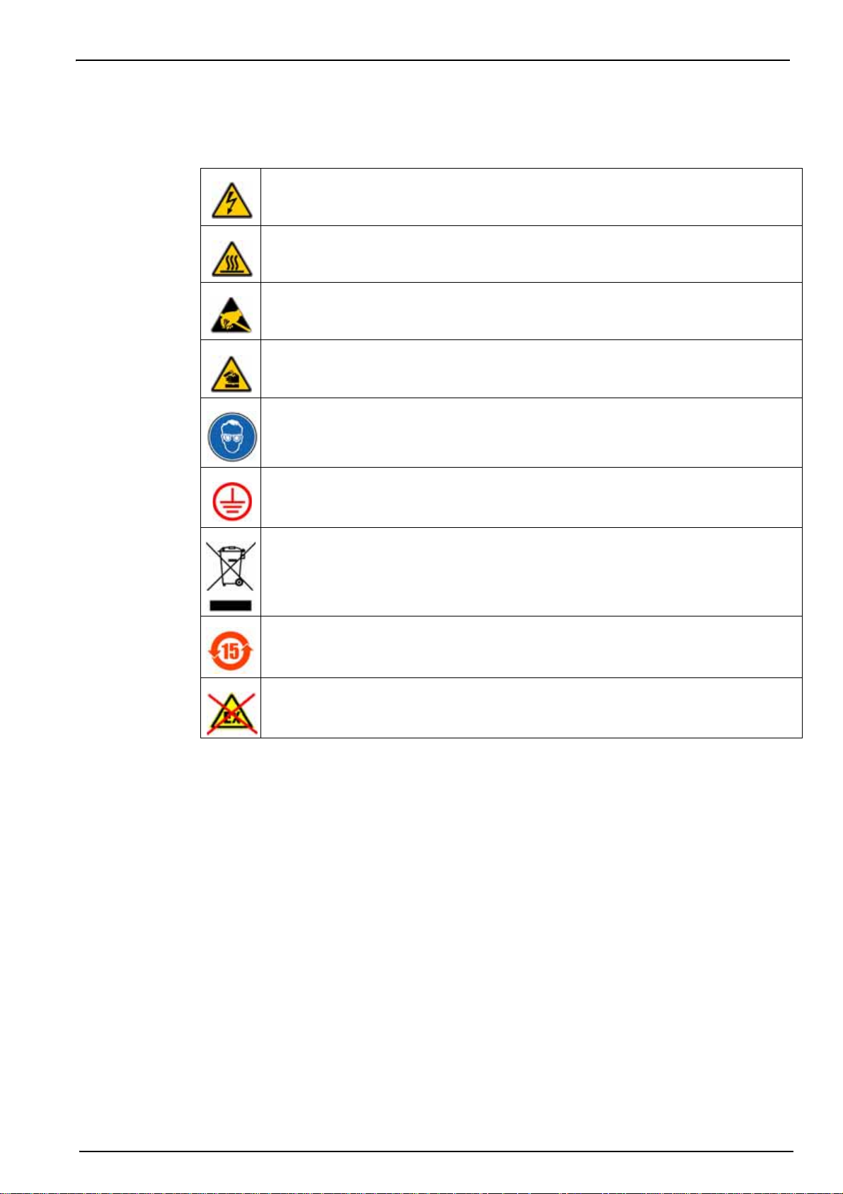
1.3.5 Precautionary labels
Read all labels and tags attached to the instrument. Personal injury or damage to the instrument
could occur if not observed.
This symbol, when noted on a product enclosure or barrier, indicates that a risk of electrical
shock and/or electrocution exists and indicates that only individuals qualified to work with
hazardous voltages should open the enclosure or remove the barrier.
This symbol, when noted on the product, indicates that the marked item can be hot and
should not be touched without care.
This symbol, when noted on the product, indicates the presence of devices sensitive to
electrostatic discharge and indicates that care must be taken to prevent damage to them.
This symbol, when noted on the product, identifies a risk of chemical harm and indicates that
only individuals qualified and trained to work with chemicals should handle chemicals or
perform maintenance on chemical delivery systems associated with the equipment.
This symbol, if noted on the product, indicates the need for protective eye wear.
General Information
This symbol, when noted on the product, identifies the location of the connection for protective
earth (ground).
Electrical equipment marked with this symbol may not be disposed of in European public
disposal systems. In conformity with European local and national regulations, European
electrical equipment users must now return old or end-of-life equipment to the manufacturer
for disposal at no charge to the user.
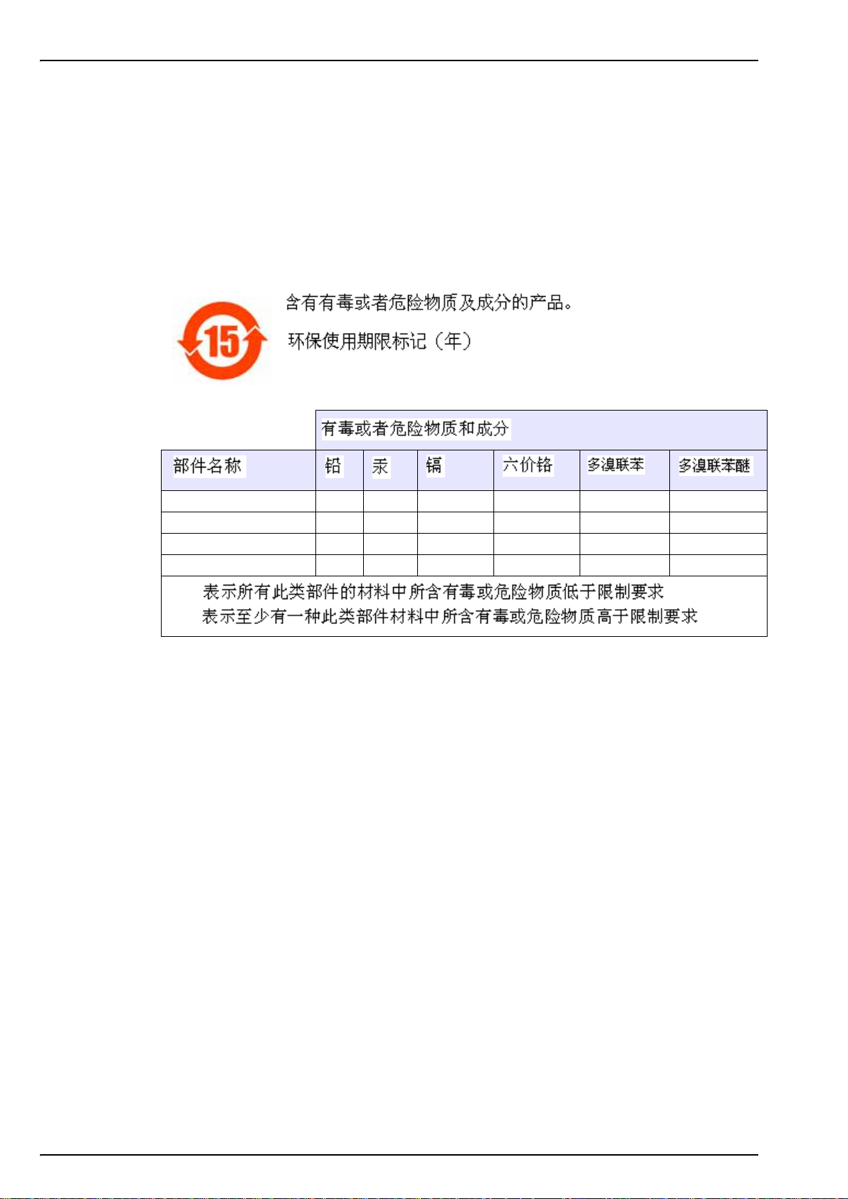
Products marked with this symbol indicates that the product contains toxic or hazardous
substances or elements. The number inside the symbol indicates the environmental protection
use period in years.
Products marked with this symbol indicates that the product must only be used in the safe
and never in the explosive area.
area
5
Page 8
General Information
1.4 Intrinsically safe conformity
Orbisphere series 3650Ex analyzers for gas measurement have been certified as Intrinsically
Safe by:
LCIE (Laboratoire Central des Industries Electriques),
33 av. Division Leclerc, Fontenay aux Roses 92260, France.
Note: LCIE is a notified body number 0081 in accordance with article 9 of Directive 94/9/CE of the
European Parliament and Council of 23 March 1994.
LCIE certifies that the electrical apparatus has been found to comply with the essential Health
and Safety Requirements: EN 60079-0 (2006), EN 60079-11 (2007).
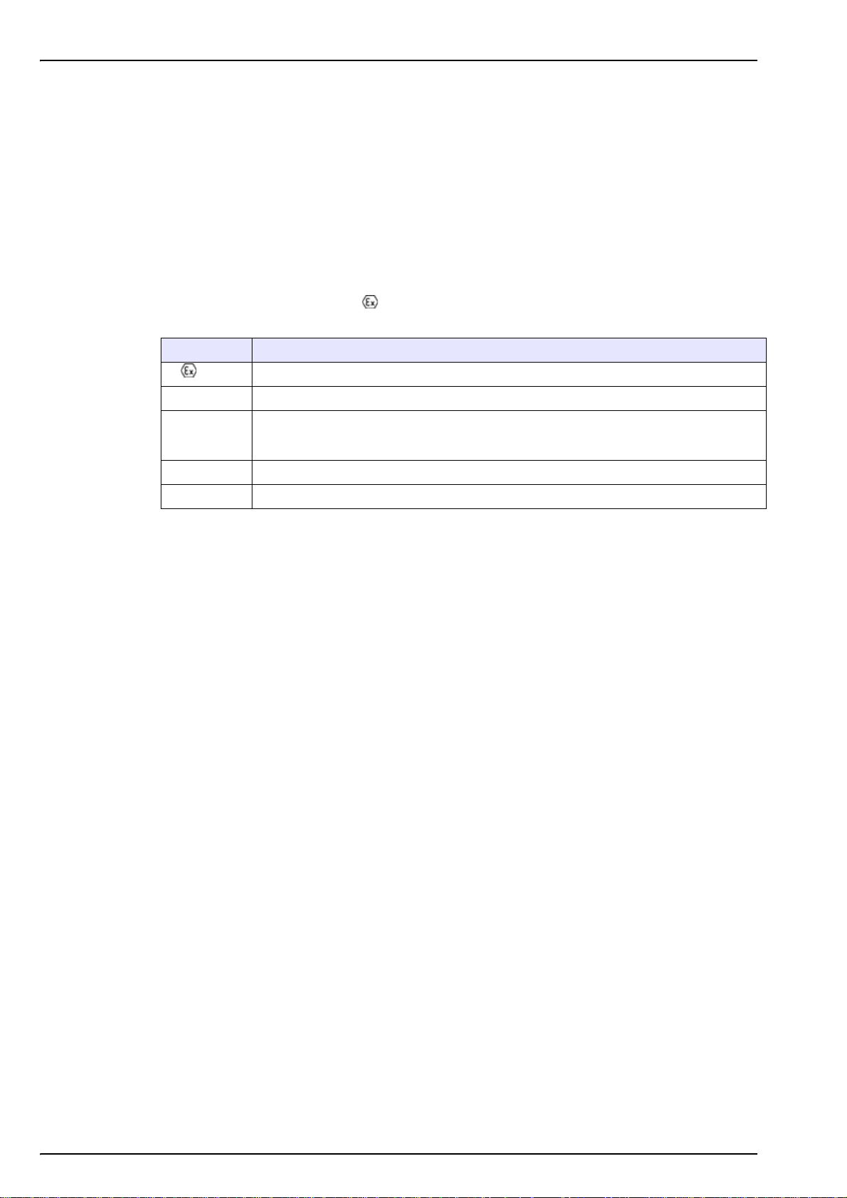
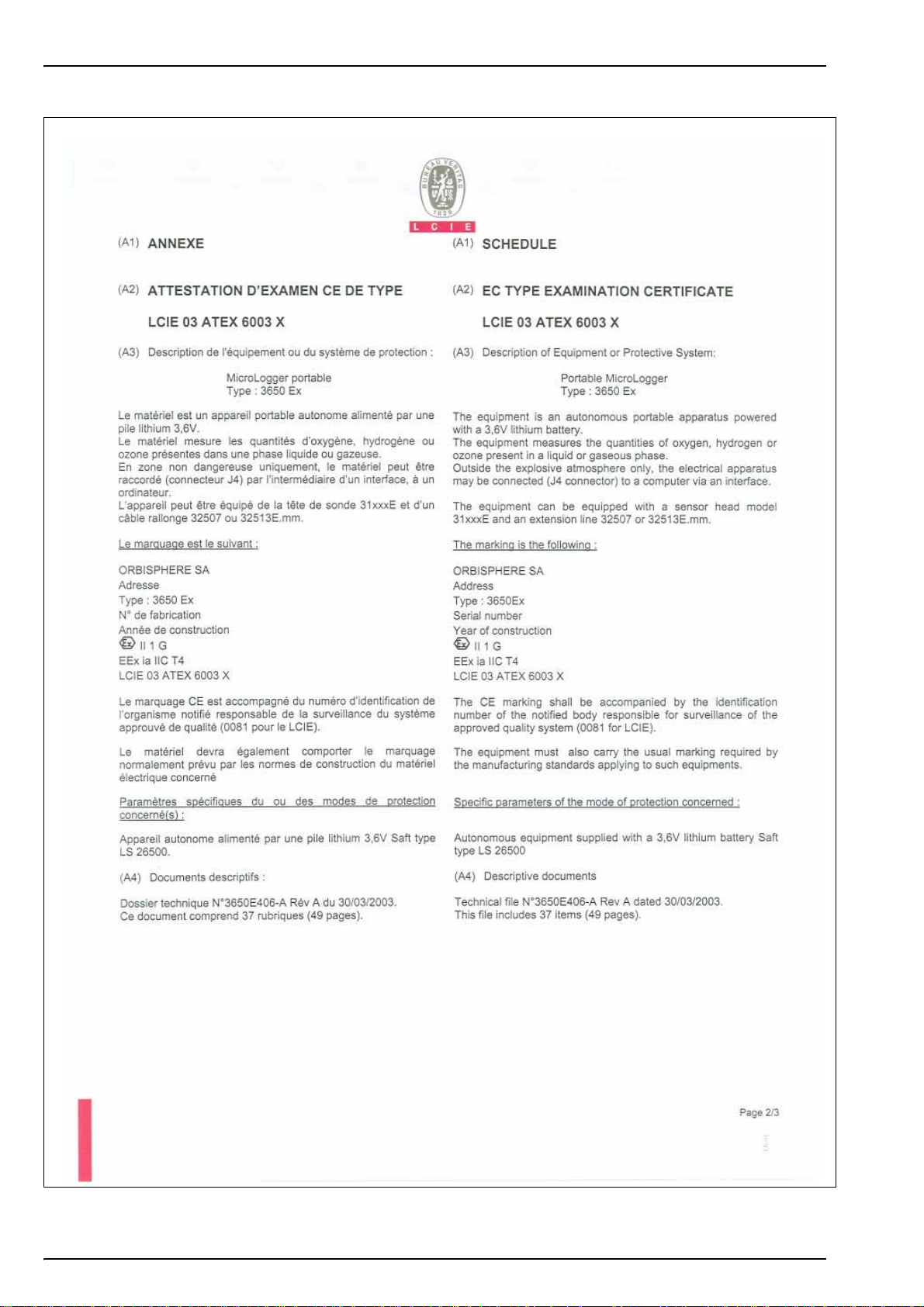
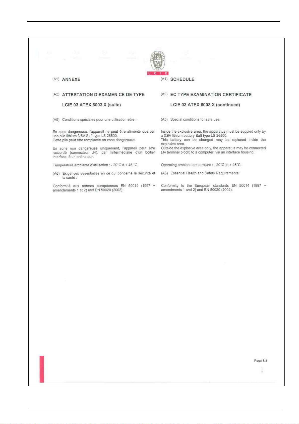
These instruments are certified II 1G Ex ia IIC T4 under EC type Examination Certificate
number LCIE 03 ATEX 6003 X (see 3650Ex certificates on page 13)
Category Explanation
II 1 G ATEX marking: Surface apparatus with permanent explosive gas presence.
Ex Explosion-proof apparatus built to the universal standards below:
Type of protection: The highest category, based on a safety factor of 1.5 on two faults.
ia
IIC Gas group: Corresponds to the most flammable gases, including hydrogen.
T4 Temperature category: Maximum surface temperature of 135º C.
No combination of two faults in the 3650Ex can produce a spark, or heating, causing
ignition of an explosive atmosphere.
6
Page 9
1.5 Product recycling information
ENGLISH
Electrical equipment marked with this symbol may not be disposed of in
European public disposal systems after 12 August 2005. In conformity with
European local and national regulations (EU Directive 2002/96/EC), European
electrical equipment users must now return old or end-of-life equipment to the
manufacturer for disposal at no charge to the user.
Note: For return for recycling, please contact the equipment
manufacturer or supplier for instructions on how to return end-of-life
equipment for proper disposal.
DEUTSCH
Elektrogeräte, die mit diesem Symbol gekennzeichnet sind, dürfen in Europa nach dem 12.
August 2005 nicht mehr über die öffentliche Abfallentsorgung entsorgt werden. In
Übereinstimmung mit lokalen und nationalen europäischen Bestimmungen (EU-Richtlinie
2002/96/EC), müssen Benutzer von Elektrogeräten in Europa ab diesem Zeitpunkt alte bzw. zu
verschrottende Geräte zur Entsorgung kostenfrei an den Hersteller zurückgeben.
Hinweis: Bitte wenden Sie sich an den Hersteller bzw. an den Händler, von dem Sie das Gerät
bezogen haben, um Informationen zur Rückgabe des Altgeräts zur ordnungsgemäßen
Entsorgung zu erhalten.
General Information
FRANCAIS
A partir du 12 août 2005, il est interdit de mettre au rebut le matériel électrique marqué de ce
symbole par les voies habituelles de déchetterie publique. Conformément à la réglementation
européenne (directive UE 2002/96/EC), les utilisateurs de matériel électrique en Europe doivent
désormais retourner le matériel usé ou périmé au fabricant pour élimination, sans frais pour
l'utilisateur.
Remarque: Veuillez vous adresser au fabricant ou au fournisseur du matériel pour les
instructions de retour du matériel usé ou périmé aux fins d'élimination conforme.
ITALIANO
Le apparecchiature elettriche con apposto questo simbolo non possono essere smaltite nelle
discariche pubbliche europee successivamente al 12 agosto 2005. In conformità alle normative
europee locali e nazionali (Direttiva UE 2002/96/EC), gli utilizzatori europei di apparecchiature
elettriche devono restituire al produttore le apparecchiature vecchie o a fine vita per lo
smaltimento senza alcun costo a carico dell’utilizzatore.
Nota: Per conoscere le modalità di restituzione delle apparecchiature a fine vita da riciclare,
contattare il produttore o il fornitore dell’apparecchiatura per un corretto smaltimento.
DANSK
Elektriske apparater, der er mærket med dette symbol, må ikke bortskaffes i europæiske offentlige
affaldssystemer efter den 12. august 2005. I henhold til europæiske lokale og nationale regler
(EU-direktiv 2002/96/EF) skal europæiske brugere af elektriske apparater nu returnere gamle eller
udtjente apparater til producenten med henblik på bortskaffelse uden omkostninger for brugeren.
Bemærk: I forbindelse med returnering til genbrug skal du kontakte producenten eller
leverandøren af apparatet for at få instruktioner om, hvordan udtjente apparater bortskaffes
korrekt.
7
Page 10

General Information
SVENSKA
Elektronikutrustning som är märkt med denna symbol kanske inte kan lämnas in på europeiska
offentliga sopstationer efter 2005-08-12. Enligt europeiska lokala och nationella föreskrifter
(EU-direktiv 2002/96/EC) måste användare av elektronikutrustning i Europa nu återlämna gammal
eller utrangerad utrustning till tillverkaren för kassering utan kostnad för användaren.
Obs! Om du ska återlämna utrustning för återvinning ska du kontakta tillverkaren av utrustningen
eller återförsäljaren för att få anvisningar om hur du återlämnar kasserad utrustning för att den ska
bortskaffas på rätt sätt.
ESPANOL
A partir del 12 de agosto de 2005, los equipos eléctricos que lleven este símbolo no deberán ser
desechados en los puntos limpios europeos. De conformidad con las normativas europeas
locales y nacionales (Directiva de la UE 2002/96/EC), a partir de esa fecha, los usuarios
europeos de equipos eléctricos deberán devolver los equipos usados u obsoletos al fabricante de
los mismos para su reciclado, sin coste alguno para el usuario.
Nota: Sírvase ponerse en contacto con el fabricante o proveedor de los equipos para solicitar
instrucciones sobre cómo devolver los equipos obsoletos para su correcto reciclado.
NEDERLANDS
Elektrische apparatuur die is voorzien van dit symbool mag na 12 augustus 2005 niet meer
worden afgevoerd naar Europese openbare afvalsystemen. Conform Europese lokale en
nationale wetgegeving (EU-richtlijn 2002/96/EC) dienen gebruikers van elektrische apparaten
voortaan hun oude of afgedankte apparatuur kosteloos voor recycling of vernietiging naar de
producent terug te brengen.
Nota: Als u apparatuur voor recycling terugbrengt, moet u contact opnemen met de producent of
leverancier voor instructies voor het terugbrengen van de afgedankte apparatuur voor een juiste
verwerking.
POLSKI
Sprzęt elektryczny oznaczony takim symbolem nie może być likwidowany w europejskich
systemach utylizacji po dniu 12 sierpnia 2005. Zgodnie z europejskimi, lokalnymi i państwowymi
przepisami prawa (Dyrektywa Unii Europejskiej 2002/96/EC), użytkownicy sprzętu elektrycznego
w Europie muszą obecie przekazywać Producentowi stary sprzęt lub sprzęt po okresie
użytkowania do bezpłatnej utylizacji.
Uwaga: Aby przekazać sprzęt do recyklingu, należy zwrócić się do producenta lub dostawcy
sprzętu w celu uzyskania instrukcji dotyczących procedur przekazywania do utylizacji sprzętu po
okresie użytkownia.
PORTUGUES
Qualquer equipamento eléctrico que ostente este símbolo não poderá ser eliminado através dos
sistemas públicos europeus de tratamento de resíduos sólidos a partir de 12 de Agosto de 2005.
De acordo com as normas locais e europeias (Directiva Europeia 2002/96/EC), os utilizadores
europeus de equipamentos eléctricos deverão agora devolver os seus equipamentos velhos ou
em fim de vida ao produtor para o respectivo tratamento sem quaisquer custos para o utilizador.
Nota: No que toca à devolução para reciclagem, por favor, contacte o produtor ou fornecedor do
equipamento para instruções de devolução de equipamento em fim de vida para a sua correcta
eliminação.
8
Page 11

1.6 Product disposal
Note: The following only applies to European customers.
Hach Lange is committed to ensuring that the risk of any environmental damage or pollution
caused by any of its products is minimized as far as possible. The European Waste Electrical
and Electronic Equipment (WEEE) Directive (2002/96/EC) that came into force on August 13
2005 aims to reduce the waste arising from electrical and electronic equipment; and improve the
environmental performance of all those involved in the life cycle of electrical and electronic
equipment.
In conformity with European local and national regulations (EU Directive 2002/96/EC stated
above), electrical equipment marked with the above symbol may not be disposed of in
European public disposal systems after 12 August 2005.
General Information
Hach Lange will offer to take back (free of charge to the customer) any old, unserviceable or
redundant analyzers and systems which carry the above symbol, and which were originally
supplied by Hach Lange. Hach Lange will then be responsible for the disposal of this
equipment.
In addition, Hach Lange will offer to take back (at cost to the customer) any old, unserviceable
or redundant analyzers and systems which do not carry the above symbol, but which were
originally supplied by Hach Lange. Hach Lange will then be responsible for the disposal of this
equipment.
Should you wish to arrange for the disposal of any piece of equipment originally supplied by
Hach Lange, please contact your supplier or our After Sales Service department in Geneva for
instructions on how to return this equipment for proper disposal.
9
Page 12
General Information
1.7 Restriction of hazardous substances (RoHS)
The European Union RoHS Directive and subsequent regulations introduced in member states
and other countries limits the use of six hazardous substances used in the manufacturing of
electrical and electronic equipment.
Currently, monitoring and control instruments do not fall within the scope of the RoHS Directive,
however Hach Lange has taken the decision to adopt the recommendations in the Directive as
the target for all future product design and component purchasing.
Note: The following only applies to exports of this product into the People’s Republic of China.
1152A Battery protection X
1200D Logic board X
1201F Analog board X
OO 401491 Regulator X
O:
X:
10
Page 13
Section 2 Specifications and Certifications
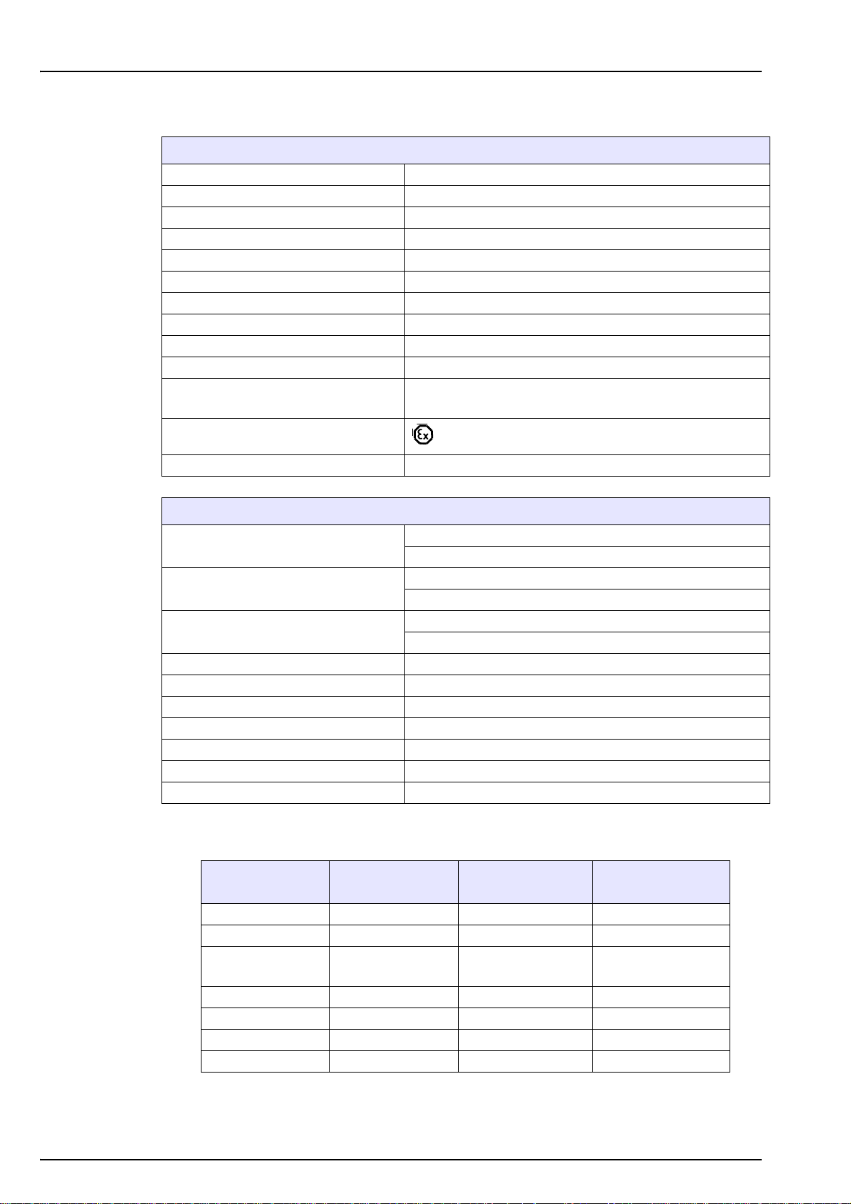
2.1 General technical data
3650EX Instrument
Power Supply Model 32960 non-rechargeable lithium battery
Battery Autonomy 60 hours continuous use
Signal Drift < 0.5% of reading between service
Serial Output (RS232) Baud rate: 9600; Stop Bits: 1; Start Bits: 0; Parity: None;
Temperature Compensation Range -5 to 60°C
Instrument Operating Limits 0 to 45°C
Dimensions (HxWxD) 150 mm x 115 mm x 220 mm
Weight 2.4 kg
Enclosure IP 65/NEMA 4
EMC Requirements EN 61326 (2006)
EXPROOF Requirements
LCIE 03 ATEX 6003 X II 1 G, Ex ia IIC T4
ISO Certification ISO9001/EN29001
EN 60079-0 (2009)
EN 60079-11 (2012)
Power Supply
Power Consumption
Fuse
Operating Limits 0 to 45°C
Dimensions (HxWxD) 70 mm x 140 mm x 190 mm
Weight 0.65 kg
Enclosure IP 20
Enclosure material ABS FR (V0)
EMC Directive 2004/108/EC EN 61326-1 (2006)
LVD Directive 2006/95/EC EN 61010-1 (2010)
2.2 Analyzer gas and display options
Instrument Model Gas Measured Display Units
3650EX/111 Oxygen ppm/ppb (liquid) 0.01 ppb
3650EX/112 Oxygen %/ppm (gaseous) 0.01 ppm
3650EX/113 Oxygen
3650EX/114 Oxygen kPa/Pa (gaseous) 0.01 Pa
3650EX/115 Oxygen bar/mbar (gaseous) 0.001 mbar
3650EX/211 Hydrogen ppm/ppb (liquid) 0.01 ppb
3650EX/212 Hydrogen %/ppm (gaseous) 0.01 ppm
29122 Interface Box
120Vac 50/60Hz (Model 29122.A)
230Vac 50/60Hz (Model 29122.B)
11VA (Model 29122.A)
7VA (Model 29122.B)
Max current 250mA (Model 29122.A)
Max current 100mA (Model 29122.B)
ppm (liquid)
% (gaseous)
0.001 ppm
0.001%
Maximum Display
Resolution
11
Page 14

Specifications and Certifications
2.3 Theory of operation
2.3.1 Measuring oxygen
The sensor circuitry performs four functions:
• Applying a constant voltage to the anode
• Measuring the current flowing through the sensor
• Compensating this current for sample temperature variations
• Converting these resulting signals into a scaled current or voltage
The anode is held positive with respect to the cathode. Current flowing through the sensor due
to oxygen reduction at the cathode is converted to a voltage by an amplifier, the proportionality
between voltage and current being determined by the feedback resistance of this amplifier.
The output voltage is essentially a function of oxygen activity (partial pressure), temperature and
membrane permeability. Corrections for variations in membrane permeability are made when
the sensor is calibrated. The temperature compensation circuit accounts for temperature
variations. Hence the output voltage varies only with oxygen concentration.
2.3.2 Measuring hydrogen
The sensor circuitry performs four functions:
• Maintaining a zero potential to the anode
• Measuring the current flowing through the sensor
• Compensating this current for sample temperature variations
• Converting these resulting signals into a scaled current or voltage
The anode is held neutral with respect to the cathode. Current flowing through the sensor due to
hydrogen oxidation at the anode is converted to a voltage by an amplifier, the proportionality
between voltage and current being determined by the feedback resistance of this amplifier.
The output voltage is essentially a function of hydrogen activity (partial pressure), temperature
and membrane permeability. Corrections for variations in membrane permeability are made
when the sensor is calibrated. The temperature compensation circuit accounts for temperature
variations. Hence the output voltage varies only with hydrogen concentration.
12
Page 15
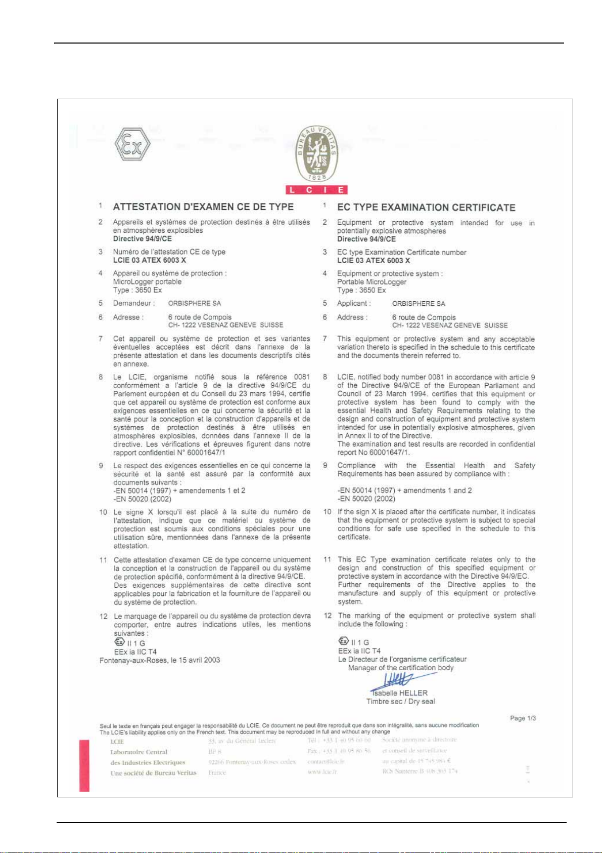
2.4 3650Ex certificates
Specifications and Certifications
13
Page 16
Specifications and Certifications
14
Page 17
Specifications and Certifications
15
Page 18

Specifications and Certifications
16
Page 19

Specifications and Certifications
17
Page 20

Specifications and Certifications
18
Page 21

Section 3 Installation
Electrical danger and fire hazard. Only use the supplied power cable. Only qualified experts
may perform the tasks detailed in the installation section of this manual, while adhering to all
locally valid safety regulations.
This section provides necessary information to install and connect the instrument. Should you
have any questions, do not hesitate to contact your Hach Lange representative regarding the
installation procedure.
The series 3650Ex Intrinsically Safe Portable Analyzer is a self-contained instrument configured
to make oxygen or hydrogen gas concentration measurements with Electrochemical (EC)
Sensors in a hazardous area, in either liquid or gaseous samples.
WARNING
Figure 1 3650Ex instrument
1. Flow Chamber 4. Battery Cap
2. Electrochemical (EC) Sensor 5. Barometric Pressure Sensor Relief Valve
3. Pseudo RS-232 Port
Refer to Instrument configurations on page 49 for a complete list of the instrument
configurations available.
Up to 500 measurement values can be stored in memory and downloaded to a personal
computer for further analysis.
The instrument is a portable unit and should be located convenient to the sample being
analyzed.
• This instrument is powered by a special non-rechargeable Exproof lithium
battery (model 32960).
• The battery may be changed in the hazardous area.
• Do not short circuit the battery.
• The instrument can be connected to a PC via the Interface Box (model 29122)
only in a safe area.
19
Page 22

Installation
Sensor Signal LEMO-10 Pin
Guard ring electrode Pin 1
Not used Pin 2
Temperature measurement Pin 3
Counter electrode Pin 4
Not used Pin 5
Temperature measurement Pin 6
Not used Pin 7
Not used Pin 8
Working electrode Pin 9
Not used Pin 10
3.1 Sensor installation
The electrochemical (EC) sensor connects to the instrument base through a 10-pin LEMO
connector. A locking nut holds the sensor in place. Generally, the sensor is shipped already
installed in the instrument. If this is not the case, for full installation instructions, please refer to
the Sensor Manual provided with your instrument.
3.2 Flow chamber installation
The model 32007E flow chamber draws the liquid or gaseous sample past the EC sensor. It
attaches to the sensor with a threaded collar and is then sealed to the sensor with two O-rings.
20
The flow chamber’s centrally located inlet and eccentrically located outlet use either ¼-inch or
6-mm diameter transparent plastic tubing. Connect by compression fittings to the sample source
and to the drain, respectively.
You may also have received a model 32051 sample tube adapter to attach the flow chamber
inlet tubing to the sampling point (see next section entitled Sample tube adapter (optional)).
Figure 2 3650Ex (rear view) with 32007E flow chamber
Page 23

3.3 Sample tube adapter (optional)
A model 32051A sample tube adapter can be attached to the flow chamber's inlet tubing. This
adapter, in turn, attaches to 6 mm or ¼ inch stainless steel or flexible tubing using rubber gasket
model 32813 (or, for 8 mm tubing, rubber gasket model 32814).
The tightening ring provides a compression fitting to the sample tube.
3.4 WinLog97 PC program installation
Install the WinLog97 program onto the PC by inserting the accompanying CD into your PC and
running the SetUp program. Simply follow the on-screen instructions.
When finished, a new Windows Program Group labeled Orbisphere is created containing the
software and help files.
Installation
3.5 Connections
3.5.1 3650Ex Instrument - PC connection
Explosion hazard. Only use the Interface Box 29122 in the safe area and never in the
explosive area.
WARNING
Figure 3 3650Ex instrument to PC connection
The model 29122 interface box must be used to connect the 3650EX instrument to a personal
computer (PC) as illustrated in Figure 3. This unit converts TTL digital signals from the
instrument to RS-232 compatible signals.
• This connection should be made exclusively within the safe area
21
Page 24

Installation
Pseudo RS232 Signal
LEMO-6
Pin
Transmitted data (TTL-TXD) Pin 1
Received data (TTL-RXD) Pin 2
Not used Pin 3
Not used Pin 4
External voltage input (used with the model 29122 interface,
only in safe area)
Pin 5
Ground Pin 6
Pin Use
Pin 1 Not Used
Pin 2 TTL Transmitted Data (TXD)
Pin 3 TTL Received Data (RXD)
Pin 4 Not Used
Pin 5 Power Supply (V+)
Pin 6 Not Used
Pin 7 Not Used
Pin 8 Not Used
Pin 9 Ground
Pin Use
Pin 1 Not Used
Pin 2 RS-232 Transmitted Data (TXD)
Pin 3 RS-232 Received Data (RXD)
Pin 4 Not Used
Pin 5 Ground
Pin 6 Not Used
Pin 7 Not Used
Pin 8 Not Used
Pin 9 Not Used
The interface box operates from 115 VAC or 230 VAC power. Make sure that the power is
correct before connecting to a power supply. A green power LED is illuminated when the box is
plugged into the power source.
Two cables are supplied with the model 29122 interface box:
• A model 32511 cable for connection between the 3650EX instrument LEMO-6 connector and
the interface box
• A model 32538 cable for connection between the interface box and the PC.
The connections should be made as indicated in Figure 3.
Note: When the Interface Box is connected to the 3650Ex instrument, this also acts as a power supply to
the instrument and disconnects the internal battery power source.
22
Note: If you use an adapter for the connection to the PC, make sure it is designed for this purpose and,
thus, has all nine pins accessible. Some 25-to-9 pin adapters are supplied for specific use, such as a
mouse, and these may have only certain pins available.
Page 25

3.6 Installation completion check list
3.6.1 Battery
The instrument is designed to work on battery power.
Install the Exproof lithium battery by first unscrewing the instrument's battery cap located on the
right side of the instrument (see Figure 1 on page 19) with a coin or flat screwdriver. Then insert
the battery pack lengthwise, positive end first, and replace the cap.
• Only the model 32960 battery can be used with this instrument.
• The battery may be installed or changed in the hazardous area
The power autonomy of the instrument is about 60 hours with a new battery. If battery power
should drop, a LO BAT warning appears in the instrument LCD's top-left corner.
3.6.2 Electrical connections
The LEMO-6 connector on the right side of the instrument (see Figure 1 on page 19) is used for
the connection to a PC. To connect the instrument to a PC, use the model 29122 interface box
(see also 3650Ex Instrument - PC connection on page 21).
Installation
• The instrument to PC connection should be used only in a safe area.
Remember, connecting the instrument to the interface box means it is now powered by mains
power and the battery power is by-passed.
3.6.3 Instrument clock setting
If you use the instrument to store measurements for downloading to a PC, you should verify the
date and time settings of the instrument's internal clock, as described in Clock settings on
page 46.
3.6.4 Electrochemical sensor
Before making any measurements, for A1100 ATEX sensors perform the preparation procedure
in the A1100 Sen sor Ma nua l. For other ATEX sensors perform the sensor service procedure as
described in the EC Sensor Manual.
3.6.5 Flow chamber
The model 32007E flow chamber's inlet and outlet should be free of any obstructions. It is
mounted by means of the sensor's collar, as shown in Figure 2 on page 20. A guide pin on the
flow chamber surface prevents twisting during operation.
When switching from liquid to gaseous samples, ensure that the sensor membrane is dry.
Ensure that the gas from the exit tube of the flow chamber (in gaseous mode) is released at
atmospheric pressure and that it is constant.
3.7 Storage when not used
At the end of the workday clean the outside of the instrument and interface box (if used) with a
damp cloth. Run clean water through the flow chamber to prevent passageways from clogging.
You may wish to repeat sensor preconditioning (see Preconditioning sensors on page 27) prior
to the next use.
If you do not expect not to use your sensor for more than a few months, you should clean the
sensor as instructed in the Sensor Manual and then store it dry and with the calibration cap in
place for protection.
23
Page 26

Installation
24
Page 27

Section 4 Operating Information
4.1 Operating controls
The front panel of the instrument has a three-digit liquid crystal display (LCD). The LCD includes
a right-side marker to distinguish between gas concentration and temperature display. This
marker also indicates the measurement display units (ppm, ppb, %, etc.) depending on the
instrument model. To the LCD's right is a label showing the measurement units configured at the
factory for your application.
In addition to the controls indicated on the front panel, there is also a pressure relief valve
switch on top of the instrument (as indicated in Figure 1 on page 19) to enable atmospheric
pressure equilibrium for sensor calibration, or for measurements in gaseous samples in % units.
The panel keyboard has the following push-button controls:
Power switch. This turns instrument power on or off. The instrument starts in measurement
mode
Places the instrument in measurement mode
Calibrates the analyzer against a reference sample. This button can be locked out from
the WinLog97 PC program
Stores a measurement value into memory
Backlights the LCD for approximately three minutes
Toggles between gas concentration and temperature measurement displays in
measurement mode, increases or decreases the storage number during storage or
memory view, or sets a calibration value during calibration
25
Page 28

Operating Information
To start the analyzer, press the keyboard POWER switch (located bottom left of the keyboard).
When you turn power on, the instrument displays its model number briefly, and then starts in
measurement mode.
You can access other instrument functions by pushing one of these keys while turning power on:
Sensor calibration - see Sensor calibration on page 42
Start automatic data acquisition - see Automatic data acquisition on page 28
Start memory storage view - see Viewing stored measurements on page 30
Display program identification information
Once you have completed the installation and start-up procedures defined in Installation on
page 19, the instrument can be operated independently, making measurements as a portable
oxygen or hydrogen analyzer. You may store these measurement values for later analysis via
the WinLog97 program (on your personal computer) or the memory view mode (on the
instrument). The WinLog97 program operation is described in detail throughout the manual,
where relevant.
26
Page 29

4.2 Taking measurements
Once the system is calibrated, you should be able to begin taking measurements. Connect the
top-mounted inlet to accept your sample, typically this is accomplished by connection to a
sampling valve. The sample flow can be regulated by adjusting the knurled stainless steel knob
on top of the flow chamber.
Minimum flow rates, measurement limits and response times for the various available
membranes are given in the accompanying Sensor Manual.
The LCD includes a right-side marker to distinguish between gas concentration measurements
and temperature. This marker also indicates the measurement display units (ppm, ppb, %, kPa
or mbar depending on the instrument model).
To switch between gas measurement and temperature measurement, press the Up/Down
Arrow buttons.
To backlight the LCD for approximately three minutes, press the Backlight button.
Note: For measurements of gaseous samples in % units, you must open the barometric pressure sensor
relief valve switch on the top of the instrument from time to time, to allow the pressure inside the instrument
to equilibrate to the barometric pressure.
4.2.1 Preconditioning sensors
Operating Information
You can expect a more rapid and accurate first result if you precondition the sensor before you
take readings.
To precondition, connect the flow chamber to a convenient sampling source at or below
expected O
carbonated water. Open the sampling valve on the flow chamber, just enough for a trickle. Then,
switch on the instrument and watch the LCD. You will see the values drop.
Typically for oxygen, if you are measuring in the 0.1 ppm range, then only a short time is
required for the display to fall to this level, whereas ppb level measurements may require the
sensor to remain exposed to the sample for half an hour or more. You will establish your own
requirement with experience.
Once the LCD displays the expected level of O
preconditioned and ready to use.
You may want to precondition prior to each series of measurements, depending on frequency of
use.
or H2 levels. If measurements take place in carbonated samples, precondition with
2
or H2, close off the sample. The sensor is now
2
27
Page 30

Operating Information
4.3 Storing measurements in the instrument
The instrument will store up to 500 gas measurement values, labeled by numbers 0 through
499, along with the current date and time of each measurement. You have the choice of
acquiring this information manually or automatically, as described below.
Before storing measurements, you should verify the date and time settings of the instrument's
internal clock, as described in Clock settings on page 46.
4.3.1 Automatic data acquisition
Note: When the instrument is used to automatically store measurement data, all buttons except the
POWER key are disabled. If enough time elapses to store all 500 values, the instrument will return to
normal measurement mode and the buttons re-enabled.
Before starting automatic measurement storage, first select the sampling rate desired using the
Sampling Rate menu of the WinLog97 program (see Automatic data acquisition - Setting
sampling intervals on page 37).
1. Switch the instrument OFF (by pressing the POWER
key)
2. Then hold down the STO button while switching the
instrument back ON. The LCD displays the message
Sto for about one second
3. Normal gas concentration measurements are
displayed for about two minutes
4. After two minutes the instrument displays the sample
number (starting at 000), then the gas concentration
measurement value followed by [---] to indicate
the measurement is being stored.
5. This storage sequence repeats automatically, at the
rate specified by the WinLog97 program Sampling
Rate menu. Values are stored sequentially in sample
numbers 000 through 499.
Note: If you have not cleared previously stored values, the storage sequence automatically overwrites the
older values, as they are stored.
28
To end automatic storage, switch the instrument OFF (by pressing the POWER key) while it is in
normal measurement mode and not while it is in the process of automatically storing data.
Switching ON again without holding down the STO button returns the instrument to
measurement mode.
Note: If you accidentally interrupt the automatic data storage by switching off the instrument while it is in the
process of storing a value, and you then attempt to download the stored values by the WinLog97 program,
you will get a Windows Checksum Error message, and you will not be able to view the measurement data.
If this happens, then go back to the instrument and manually log one more value (as described in Manual
data acquisition on page 29). You can then download your original set of values to your PC.
Page 31

4.3.2 Manual data acquisition
Note: You cannot store measurement data manually if the instrument has already been set up to store the
data automatically.
Operating Information
1. For the first measurement you wish to store,
press the STO button once to display a sample
number. The default sample number is 000 (for
first time access), or the last used memory
position where data was stored, incremented by
a value of 1.
2. You can increase or decrease this number by
pressing the Up/Down Arrow buttons within
three seconds.
3. Should you decide at this point, not to store this
particular measurement, just wait five seconds
and the display returns to measurement mode.
You may also exit this routine by pressing the
MEAS button.
4. Press STO a second time, within five seconds of
the first. The instrument then displays a brief
clearing [---] message, followed by the gas
concentration measurement value for about
three seconds (e.g. 8.56 in the flow diagram)
5. The [---] message is displayed as this
measurement value is stored
6. Repeat the above steps to store additional
measurements.
If you stored the first value as sample 001, the instrument automatically increases the next
storage location, and labels it sample 002. You can increase or decrease this number by
pressing the Up/Down Arrow buttons.
Note: If you label a sample number the same as a previously stored measurement value, the new
measurement value overwrites the previously stored value.
29
Page 32

Operating Information
4.3.3 Viewing stored measurements
1. Switch the instrument OFF (by pressing
the POWER key)
2. Hold down the Up Arrow button while
switching the instrument back ON. The
LCD displays a sample location number.
3. Scroll through the numbered sample
locations of all the stored values using the
Up Arrow and Down Arrow buttons.
4. To view the actual gas concentration
measurement value at a particular sample
number, press the STO button. The LCD
now displays the stored value for that
sample number.
5. Press STO a second time to return to the
next numbered location display, to
continue scrolling or view another stored
value.
To return to the measurement mode, switch the instrument OFF and then back ON again
without holding down any additional buttons.
4.4 Storing and accessing measurements from the PC
If you have made measurements and stored them in the instrument, you should be ready to
bring them into the WinLog97 program for viewing, copying, saving and printing. See also
Options Setup on page 35 for additional information on the WinLog97 program.
4.4.1 Downloading stored values
To download the stored results from the instrument to the PC, choose the DownLoad data
command from the Logger menu.
The DownLoad window presents a display of the stored measurements from the instrument.
The window displays five columns of data:
• Sample (sequence number of the sample)
• Gas (concentration of the measured gas)
• Date (date of the measurement)
• Time (time of the measurement)
• Sample Description
The descriptions can be modified for your applications using the procedures described below.
30
Page 33

4.4.2 Altering the sampling point descriptions
For help in identifying the locations of various sampling points that are stored by the instrument,
you may choose the Sampling Point Description command from the Logger menu to bring up
the dialog box.
Operating Information
The measurement values to be placed in positions 0 through 499 (identified as Text 0, Text 1...
etc.) can be described however you wish. Double-click on a particular position (or click Modify),
then type a description in the box as shown (e.g. Tank 3). Choose OK when finished entering a
description.
When you Close this box, your modifications will be saved, and will appear in the Sample
Description column for the next downloaded list. These descriptions can be modified again
later as your requirements change.
4.4.3 Copying values
To copy the results to the Windows Clipboard, so that the data can be pasted into a
spreadsheet, word processor or other Windows program that accepts tabular text information,
choose the Clipboard command from the Export menu.
4.4.4 Saving values
To save this list of measurements as a text (.txt) file, capable of being recalled by the WinLog97
program or imported as a file into other Windows programs, choose the Save As command
from the File menu. A dialog box appears, with a space to fill in with an eight-letter name. (The
program automatically attaches a .txt suffix to these files.) If you have saved previous files, a
grayed-out list of these names appears as well. Typical to Windows programs, Directories and
Drives boxes can be used to locate other places to save (e.g. on a floppy disk). You may also
type the drive and directory yourself when saving the file.
4.4.5 Printing values
To place this list of measurements into a tabular format
and send it to the Windows printer, choose the Print
command from the File menu. The program asks you
to enter Title and Author information. Note that the
Date is fixed by your operating system.
The resulting printed list will include this information on
each page.
31
Page 34

Operating Information
4.4.6 Clearing stored values
To clear all the values stored in the instrument via the WinLog97 program, choose the Clear
Data command from the Logger menu. Since this action will clear the storage memory of the
instrument, a warning appears first.
Choose OK to bring up the next dialog box to confirm the clear action.
Choose Clear to start the memory clear operation. A message, Reset should be completed
appears in this box when the task is finished.
Note: You can accomplish the same thing passively, by simply allowing the analyzer to overwrite a set of
stored values with new ones.
4.5 Monitoring measurements in real-time
You may wish to analyze a particular sampling point via the WinLog97 program's Monitoring
menu. To use this Monitoring chart, the instrument must be connected to your PC.
Choose Monitoring from the WinLog97 menu to bring up a chart display.
32
The Monitoring chart shows the gas concentration (in blue), temperature (in red), and pressure
(in green) as the sample is being measured by the 3650Ex instrument. The chart is updated
directly from instrument measurements, at a rate determined by the time scale set in the
TIMEBASE box at the lower right corner of the chart.
Page 35

Operating Information
Click the TIMEBASE up/down pointers to change the time scale of the divisions of the chart.
Each division mark along the baseline (1, 2, ...10) can be made to represent from 30 seconds to
2½ hours, providing from 5 minutes to 25 hours of continuously displayed samples. The chart
updating rate is determined by the time scale selected.
Timebase Updating Rate* Maximum Samples (10 divisions)
30 Seconds/Division 5 Seconds/Sample 60
1 Minute/Division 5 Seconds/Sample 120
10 Minutes/Division 5 Seconds/Sample 1,200
30 Minutes/Division 9 Seconds/Sample 2,000
1 Hour/Division 18 Seconds/Sample 2,000
2.5 Hours/Division 45 Seconds/Sample 2,000
*This chart's updating rate is independent from the acquisition rate (see
Automatic data acquisition - Setting sampling intervals on page 37).
Click on the Continuous box, in the lower right corner, to enable or disable continuous charting.
When this box is checked, the chart scrolls continuously after reaching the 10 division, and the
oldest samples are lost off the left of the chart. When Continuous is not checked, the chart
stops displaying new results after reaching the 10 division, and all subsequent measurements
are lost.
Click the up/down pointers for each measurement variable (GAS, TEMPERATURE and
PRESSURE) at the right of the chart to change the scaling of that value on the chart. The
display of each measurement variable may be turned on or off by choosing the appropriate On
or Off switch at the right of the chart.
If your measurements do not chart properly, try using a higher or lower value scale or time base
than the one displayed. Adjust these scale factors before starting the monitoring operation.
A running display of latest sample Gas, Temperature and Pressure is also shown in the
bottom-right corner of the chart.
Use the buttons at the bottom of the chart to control real-time monitoring. Choose Go to clear
the chart and start real-time monitoring display, Stop to stop real-time monitoring and Copy to
copy the data from the chart as text information to the Windows Clipboard. This information can
be pasted from the clipboard into any Windows application, such as a spreadsheet or word
processor.
Finally, choose Close to close the Monitoring window.
33
Page 36

Operating Information
34
Page 37

Section 5 Options Setup
The WinLog97 program is an integral part of the analyzer. Running under Microsoft Windows®,
it permits you to list and analyze up to 500 stored measurement values. The program also
includes a special monitoring feature, which lets your computer act as a chart recorder, and
enables a hardware test to ensure that the system is in good working order.
5.1 Main menu basics
When you start the program, it displays the Main Menu, which automatically maximizes on
opening and appears as follows:
Throughout the WinLog97 program menus, you will see shortcut keys (such as Ctrl+P, to print a
list of stored values). As you become familiar with the program, you may choose these
keystroke commands for faster operation.
File, shown below, serves typical Windows file management needs.
WinLog97 data files can be opened, saved under a different name, closed, or printed. You can
also exit the program.
The Logger menu appears as follows. Here you can download measurement values from the
instrument, make modifications to the sample list that can be used to identify sampling point
locations, or clear the instrument's stored values.
Export places your information into the Windows Clipboard, so that it can be pasted directly into
other Windows programs. This is especially useful when working with spreadsheet programs,
but the information can be pasted into word processing programs as well.
The Monitoring menu creates a running chart of real-time measurements (see Monitoring
measurements in real-time on page 32). These can also be saved to the Windows Clipboard.
35
Page 38

Options Setup
The Configuration menu lets you see how your system has been configured for your
application. You may change the PC's COM port, the sensor membrane, automatic data
acquisition rate, or the sensor calibration mode. You may also lock out the instrument's CAL
button, or for calibration using a span gas, you may enter the span gas percentage.
The Troubleshooting menu includes a series of tests, permits the setting of the clock, and
enables a barometric pressure calibration routine.
Finally, the Help menu gives access to the Help file and allows the identification of the
WinLog97 program (version number and copyright date).
5.2 Instrument - PC connection
For the hardware connection of the instrument to a PC, see WinLog97 PC program installation
on page 21.
The Configuration, Serial port menu lets you choose one of four serial communication ports,
as follows:
Usually, COM1 is used to connect to a mouse, so try
COM2 first. You may find that a separate SetUp
program supplied with your PC is necessary to activate
this port.
Click on OK to activate the selected port. If the port you
have selected here is adequate, the WinLog97 program
will return to the main menu. Otherwise, you will see an
RS232 ERRORS message advising you to select
another port.
36
Page 39

5.3 Reviewing instrument configuration
To review if the analyzer is set up as expected, choose the Configuration, Configuration view
command.
You may change a number of these settings using the WinLog97 program. The modifiable
settings, and information relating to these settings are listed in the next section, Configuring the
instrument.
However, should you see any unexpected items listed on your screen which you are unable to
correct, please contact your Hach Lange representative.
Options Setup
5.4 Configuring the instrument
The 3650Ex analyzer can be readily configured for your application using the following
commands in the Configuration menu. The instrument must be connected to your PC in order
to change its configuration.
5.4.1 Automatic data acquisition - Setting sampling intervals
The instrument can perform as a standalone data acquisition device, automatically recording
gas measurements with the date and time, and storing up to 500 of these values. Choosing the
WinLog97 program's Configuration, Sampling Rate menu lets you select time intervals
(acquisition rate) for this storage capability.
Use the slide bar to view and select a sampling rate, from 15
seconds to 1 hour. The selected rate is shown in the
Acquisition rate window. Click OK to save this rate.
Once your choice is made, the instrument can be used
independently of the WinLog97 program for data acquisition,
as described in Automatic data acquisition on page 28.
Note: The Acquisition rate set via this menu is independent from the monitoring chart updating rate
described in Monitoring measurements in real-time on page 32. The sampling rate menu applies only to
automatic data acquisition, while the chart updating rate is used only for displaying real-time results via the
monitoring chart.
37
Page 40

Options Setup
5.4.2 Membrane selection
You may find it necessary to use a different type of membrane for different applications.
Naturally, with any membrane change, you will need to re-calibrate (see Sensor calibration on
page 42). You should also consider the changes in required flow rates and response times,
which are specified in the accompanying Sensor Manual.
To re-configure the analyzer, choose Configuration, Membrane to bring up the box which
reveals the membrane models available.
Note: Only those membranes applicable for your instrument model can be selected. All other membranes
are grayed out.
Choose OK when the desired membrane is selected.
5.4.3 Selecting type of calibration
5.4.3.1 Select from the PC
You can use the Configuration, Calibration mode command to select how the sensor is to be
calibrated.
Note: Only the calibration modes applicable to your sensor can be selected. Others will be grayed out.
Note: Calibration mode can also be selected from the instrument keyboard (see below).
5.4.3.2 Select from the instrument
Choose In Air to allow calibration of the sensor in air (only
applicable to Oxygen sensors). Choose In Line to calibrate
the sensor directly in the sampling line, in a sample of known
gas content.
In instrument models that measure gaseous samples, you
may select In a Span Gas to calibrate. Choose OK when the
desired mode is selected.
1. Switch the instrument power OFF
2. Switch the instrument on by holding down the CAL button
and then pressing the POWER button while still pressing
the CAL button
38
3. The instrument display will show either SPA for span gas
calibration, LI for in line calibration, or Air for in air
calibration
4. Use the Up/Down Arrow buttons to change the mode to
your choice
5. Press the STO button to set the selected mode. The
instrument displays Sto for a few seconds, then returns to
measurement mode
Page 41

5.4.4 Locking out the instrument’s CAL button
You can use the Configuration, Calibration Key Status menu to prevent an accidental sensor
re-calibration from the instrument keyboard.
Choose Disabled to lock out the keyboard CAL button. To
unlock this capability, choose Enabled.
Choose OK when the desired mode is selected.
5.4.5 Sensor calibration range checking
When calibration is performed for In Air and In a Span Gas calibration modes, the sensor
measurement current is compared to an ideal current for the selected membrane to determine
whether or not to complete the calibration. You can use the Configuration, Calibration Range
Checking menu to enable or disable sensor calibration range checking in the instrument.
Choose Disabled to calibrate without checking the value of the measurement current, within a
range of 0% to 999% of the ideal current.
Options Setup
When set to Enabled, at calibration the measurement current should be between 25% and
175% of the ideal current; if the value is outside of these limits, the calibration fails and Err is
displayed on the instrument LCD. Choose OK when the desired mode is selected.
Note: It is recommended to leave range checking enabled. In special measurement situations it may be
necessary to disable range checking. However, contact a Hach Lange representative for further details
before disabling this feature.
5.4.6 Entering a span gas value
When calibrating the sensor in a span gas, use the Configuration, Span Gas menu to enter the
concentration of the gas to be measured in the span gas.
Enter the percentage of measurement gas in the span gas
(e.g. 10.00%), then choose OK.
39
Page 42

Options Setup
5.4.7 Dual use (model 3650Ex/113 only)
5.4.7.1 Change from the PC
Use the Configuration, Dual Use menu to change the measurement phase (either dissolved or
gaseous) for the model 3650Ex/113 dual-use analyzer.
Choose ppm (dissolved) to set the instrument for dissolved measurement in liquids, or %
(gaseous) to set the instrument to gas phase measurement.
Note: You can also choose the measurement phase from the instrument keyboard (see below).
5.4.7.2 Change from the instrument
With this dual phase instrument, you can also select the measurement phase (dissolved or
gaseous) using the instrument panel buttons as follows.
1. Switch the instrument power OFF
2. Switch the instrument on by holding down the Down
Arrow button and then pressing the POWER button while
still pressing the Down Arrow button
3. The instrument will first display USE followed by either
dIS for dissolved phase measurement in liquids or gAS
for gaseous phase measurement
4. Use the Up/Down Arrow buttons to change the mode to
your choice
5. Press the STO button to set the selected mode. The
instrument displays Sto for a few seconds, then returns to
measurement mode
40
Page 43

Section 6 Calibrations
6.1 Atmospheric pressure equilibrium
Since the instrument is sealed against moisture, you must open the barometric pressure sensor
relief valve switch on top of the instrument (see Figure 1 on page 19 for actual location) to
permit the instrument to achieve atmospheric pressure equilibrium, and take an accurate
barometric pressure reading.
This must be done with every calibration. To open the relief valve, depress and hold down the
pressure sensor relief valve switch for five seconds, then release.
6.2 Pressure calibration
If you have access to an accurate barometer, you may wish to calibrate the instrument's internal
barometric pressure sensor. This is done using the PC WinLog97 program. Choose
Troubleshooting, Pressure Calibration and an informational message will appear to warn you
that the instrument’s current pressure calibration will be lost.
Choose OK to continue. The calibration procedure then displays a Pressure Calibration dialog
box. The Measured Pressure value shows the current instrument pressure reading.
Note: Since the instrument is sealed against moisture, you must open the barometric pressure sensor relief
valve switch (location depicted in Figure 1 on page 19) to permit the instrument to achieve atmospheric
pressure equilibrium, and take an accurate barometric pressure reading.
Enter the current atmospheric pressure, in mbars, in the Calibration Pressure entry box.
Choose Calibrate to direct the instrument to read and display the Measured Pressure using
this calibration value.
Choose Quit when you are satisfied with the pressure calibration to return to normal operation.
6.3 Calibration range checking
When calibrating the sensor in air or in a span gas, as detailed in Sensor calibration below, the
new calibration current should be between 25% to 175% of the ideal current (which is stored in
the instrument's non-volatile memory for each membrane). If not, the instrument displays Err on
its LCD and the system will not calibrate. When the system will not calibrate, it is likely that a
sensor service will be required.
See also Troubleshooting on page 45, if you suspect any problems with the analyzer.
Note: This calibration range checking can be enabled or disabled using the WinLog97 program (see Sensor
calibration range checking on page 39). It is recommended to leave this checking feature enabled. In
special measurement situations it may be necessary to disable range checking. This will allow calibration
between 0% to 999% of the ideal current. Contact a Hach Lange representative before disabling this range
checking feature.
41
Page 44

Calibrations
6.4 Sensor calibration
When delivered, the sensor is pre-calibrated. However, it should be re-calibrated on site, when
being used for the first time, and always after a membrane change. If you have just replaced the
membrane, allow at least half an hour for the membrane to settle before attempting to calibrate.
If you want to verify the accuracy of the calibration, place the analyzer back in measurement
mode and compare your displayed gas concentration against the value in the appropriate tables
found in the accompanying Calibration Tables booklet.
Your calibration is stored internally and is valid for the life of the sensor's membrane, thus it is
not necessary to repeat the calibration procedure until after the next membrane change.
The sensor can be calibrated either by using a span gas or directly in line in a liquid sample.
Additionally, oxygen sensors can be calibrated in air. The mode of calibration may be selected
using the WinLog97 program or directly from the instrument (see Selecting type of calibration on
page 38 for more details).
6.4.1 Calibration in a span gas
The span gas calibration procedure may be used if you have a supply of gas with a known
concentration in %units (use O
this type of calibration, the instrument must be set for calibration In a Span Gas. The WinLog97
program also must be used in this procedure to set the gas concentration parameter.
for oxygen sensors or H2 for hydrogen sensors). To perform
2
Switch on the instrument, if necessary, and wait a minute or so for the displayed measurement
to settle. Then expose the sensor to a span gas sample with a known gas concentration. Enter
the percentage of gas in the span gas using the WinLog97 program (see Entering a span gas
value on page 39).
1. Press the CAL button. Remember, this button may have been
locked out to prevent an accidental reset (see Locking out the
instrument’s CAL button on page 39 for details).
2. A brief clearing [---] message appears.
3. Press CAL again within a 3 second period.
4. The percentage of the measured current to the ideal one is
displayed.
5. When the reading is stable, press CAL again.
If the new calibration current is within 25% to 175% of the ideal
current, the instrument displays CAL and returns to the
measurement mode. Calibration is now complete, the sensor is
calibrated, and you can proceed with your measurements.
If the new calibration current is not within this range, the
instrument displays Err and returns to measurement mode. The
system will not calibrate, and it is likely that a sensor service will
be required.
42
Page 45

6.4.2 Calibration in line
The in line calibration procedure can be used to calibrate the sensor directly in line, against a
liquid sample with a known dissolved gas concentration. To perform this type of calibration, the
instrument must be set for calibration In line. Switch on the instrument, if necessary, and wait a
minute or so for the displayed measurement to settle. Expose the sensor to a liquid sample with
a known gas concentration.
Calibrations
1. Press the CAL button. Remember, this
button may have been locked out to prevent
an accidental reset (see Locking out the
instrument’s CAL button on page 39 for
details).
2. A brief clearing [---] message appears.
3. Press CAL again within a 3 second period.
4. A measurement will flash on the LCD,
showing the gas concentration of the
calibration sample.
5. Assuming you know the gas content to be a
certain value, you can adjust the displayed
value with the Up/Down Arrow keys.
6. When the reading is adjusted to the known
concentration, press CAL again.
7. The instrument displays CAL and returns to
the measurement mode.
43
Page 46

Calibrations
6.4.3 Calibration in air (oxygen sensors only)
The oxygen sensor can be accurately calibrated in air. To perform this type of calibration, the
instrument must be set for calibration In air.
In order to calibrate the sensor in air, you will need to extract it from its mounting or flow
chamber, and wipe dry the sensor protection grille (if applicable).
Calibration is best achieved using the storage cap that protected the sensor during shipment.
Put several drops of tap water in the cap, shake out the excess, and then attach it to the sensor
by means of its collar. It is best to leave the cap slightly loose, to avoid compressing the air
inside. The cap and sensor should be about the same temperature.
Switch on the instrument, if necessary, and wait a minute or so for the displayed measurement
to settle.
1. Press the CAL button. Remember, this button may have been
locked out to prevent an accidental reset (see Locking out the
instrument’s CAL button on page 39 for details).
2. A brief clearing [---] message appears.
3. Press CAL again within a 3 second period.
4. The percentage of the measured current to the ideal one is
displayed.
5. When the reading is stable, press CAL again.
If the new calibration current is within 25% to 175% of the ideal
current, the instrument displays CAL and returns to the
measurement mode. Calibration is now complete, the sensor is
calibrated, and you can proceed with your measurements.
If the new calibration current is not within this range, the instrument
displays Err and returns to measurement mode. The system will
not calibrate, and it is likely that a sensor service will be required.
44
Page 47

Section 7 Maintenance and Troubleshooting
7.1 Maintenance
7.1.1 Instrument
If there are problems with the instrument, please contact your local Hach Lange service
representative.
7.1.2 Sensor
For information on sensor maintenance and servicing, please refer to the accompanying
Sensor Manual.
7.2 Troubleshooting
If your analyzer is behaving strangely (failing to calibrate, giving inappropriate measurement
values, etc.) and you have attempted to rectify the problem by servicing the sensor, but to no
avail, you may wish to use the Troubleshooting menu of the PC WinLog97 program to make
sure that the instrument is configured correctly for your application, and is in good working
order.
The instrument must be connected to your PC and placed in measurement mode to perform
these tests.
7.2.1 Serial test
Normally, the analyzer will inform you of a disconnected RS-232 (serial) link when appropriate.
However, you can confirm a good connection using the Troubleshooting, Serial Link Test by
echoing a test message via the instrument.
7.2.2 Keyboard test
The Troubleshooting, Keyboard Test will reveal whether all the analyzer buttons are
functioning correctly.
Enter text characters in the Text to be sent box, then click
Send. If the serial link is operating correctly, the exact same
text will be displayed back from the instrument in the Echo
box.
Choose Cancel to exit from this test box.
Press any one of the instrument's buttons (except
the on/off button) for a full second or more.
The appropriate square on-screen should darken
(as illustrated for the Down Arrow button). Choose
Cancel to exit from this test box.
45
Page 48

Maintenance and Troubleshooting
7.2.3 Display test
Choosing Troubleshooting, Display Test lets you perform a one-way communication between
computer and instrument.
7.2.4 Clock settings
Choose the Clock settings command to set the date and time in the instrument.
Type a number in the Number box (you may also
select one of three units positions for the LCD's
rightmost indicator bar as well). Then choose Send.
The number and indicator bar placement should
appear on your instrument LCD.
The first screen displays the current date and time as set in the instrument. If this is correct,
choose Ok, else if either date or time must be changed, choose Modify to bring up the next
screen.
Enter the current date and time and choose Ok to store the entry into the instrument. All
measurements will be noted with the appropriate date and time when they are downloaded to
the WinLog97 program.
46
Page 49

7.2.5 Analog voltages view
The Troubleshooting, Analog Volt age View gives a real-time look at voltages used by the
system to transmit information about sensor current, temperature and pressure. This is useful
when trying to identify an instrument problem with a Hach Lange service representative either
on-site or over the phone.
The voltage limits for normal operation are:
• Current channel: -1.5 V to +1.5 V
• Temperature channel: +10 mV to +4 V
Maintenance and Troubleshooting
When performing this test, if the system is
over-range, you may receive a message
that states, for example, The current
input is saturated.
Similar messages will also appear, to warn
when temperature and pressure limits are
exceeded.
• Pressure channel: -100 mV to +100 mV
The Range window on the right side of the Current channel voltage indicates one of the four
instrument ranges: 0 (less sensitive) to 3 (most sensitive).
7.2.6 Measurements view
The Troubleshooting, Measurements View confirms, on your PC monitor, what your
instrument should be displaying on the LCD for gas concentration and sample temperature.
Choose Cancel to exit from this display.
47
Page 50

Maintenance and Troubleshooting
48
Page 51

Section 8 Part Lists
8.1 Instrument configurations
Part N° Description
3650Ex/111
3650Ex/112
3650Ex/113
3650Ex/114
3650Ex/115
3650Ex/211
3650Ex/212
8.2 Spare pa rts
Substance measured: Oxygen, RS232 (serial) output: requires part no. 29122,
Special sensor: 31120E or A1100 ATEX, Measurement units: ppm/ppb or ppm.
Substance measured: Oxygen, RS232 (serial) output: requires part no. 29122,
Special sensor: 31120E or A1100 ATEX, Measurement units: %/ppm or %.
Substance measured: Oxygen, RS232 (serial) output: requires part no. 29122,
Special sensor: 31120E or A1100 ATEX, Measurement units: ppm liquid phase, % gas phase.
Substance measured: Oxygen, RS232 (serial) output: requires part no. 29122,
Special sensor: 31120E or A1100 ATEX, Measurement units: kPa/Pa.
Substance measured: Oxygen, RS232 (serial) output: requires part no. 29122,
Special sensor: 31120E or A1100 ATEX, Measurement units: bar/mbar.
Substance measured: Hydrogen, RS232 (serial) output: requires part no. 29122,
Special sensor: 31230E, Measurement units: ppm/ppb or ppm.
Substance measured: Hydrogen, RS232 (serial) output: requires part no. 29122,
Special sensor: 31230E, Measurement units: %/ppm or %.
What follows is a listing of materials you may require to maintain your instrument. Be sure to
mention the model number and item description when ordering.
Part N° Description
32301 Electrochemical sensor cleaning and regeneration unit
32511.03 3 meter cable to connect 3650Ex instrument to interface box. Supplied with 2 connectors
32538.02
32689 Windows software (WinLog97) for 3650Ex in English, French, German, or Spanish
32813
32814
32960 3.6 V primary lithium non-rechargeable battery for 3650Ex
29122.X
31120E.01
31230E.11
32007E.110
32007E.111
32513E.04 4 meter sensor cable for 31XX0E and 3650Ex. Supplied with attached connectors
32809.MM 6x4mm plastic tubing (per meter). MM=specify total length
A110E-SVS A1100 oxygen sensor, ATEX, stainless steel, viton o-rings, cap with grille
A110E-SKS A1100 oxygen sensor, ATEX, stainless steel, kalrez o-rings, cap with grille
A110E-HVS A1100 oxygen sensor, ATEX, hastelloy, viton o-rings, cap without grille
A110E-HKS A1100 oxygen sensor, ATEX, hastelloy, kalrez o-rings, cap without grille
2 meter RS232 cable, to connect the interface box (29122) to a computer for the 3650Ex.
Supplied with 2 female 9D connectors
Rubber sealing gaskets for flow cell tubing adapters 32051 & 32051A. 6mm/¼" inside
diameter. 5 pcs
Rubber sealing gaskets for flow cell tubing adapters 32051 & 32051A. 8 mm inside
diameter. 5 pcs
PC Interface box, plus cables (32511, 32538) for 3650Ex. X: A=95-130VAC;
B=207-253VAC
EC Sensor, Substance measured: Oxygen, Sensing head material: Stainless Steel, Guard
ring: Silver, Maximum pressure: 50 bar, O-Ring: EPDM, Intrinsically safe
EC Sensor, Substance measured: Hydrogen, Sensing head material: Stainless Steel,
Guard ring: Platinum, Maximum pressure: 100 bar, O-Ring: Viton, Intrinsically safe
Flow chamber in stainless steel (316) with 6 mm fittings for use with 3650Ex. Supplied
with Viton O-rings
Flow chamber in stainless steel (316) with ¼" fittings for use with 3650Ex. Supplied with
Viton O-rings
For information on sensor spare parts and recharge kits, please refer to the accompanying
Sensor Manual.
49
Page 52

Part Lists
8.3 Accessories
Part N° Description
32051A
Adapter for attaching flow cell inlet tubing to customer's sample tube. Includes one 6 mm
(32813) and one 8 mm (32814) rubber sealing gasket.
50
Page 53

Page 54

 Loading...