

Page 1
DOC022.98.00742.JAN06
LT 200
Page 2

DOC022.98.00742.JAN06
Thermostat LT 200
Termostato LT 200
Thermostaat LT 200
Termostat LT 200
BEDIENUNGSANLEITUNG
USER MANUAL
MODE D’EMPLOI
MANUALE UTENTE
MANUAL DEL USUARIO
GEBRUIKERSHANDLEIDING
ANVÄNDARHANDBOK
BRUGSANVISNING
PODRĘCZNIK UŻYTKOWNIKA
January 2006, Edition 2
© Hach Lange GmbH, 2006. All rights reserved. Printed in Germany.
CK/SK
Page 3

2
Page 4

Thermostat LT 200
Thermostat LT 200
BEDIENUNGSANLEITUNG (deutsch) ......................................5
Thermostat LT 200
USER MANUAL (english) .......................................................41
Thermostat LT 200
MODE D’EMPLOI (français) ...................................................77
Termostato LT 200
MANUALE UTENTE (italiano) ..............................................115
Termostato LT 200
MANUAL DEL USUARIO (español) ......................................153
Thermostaat LT 200
GEBRUIKERSHANDLEIDING (nederlands) .........................191
Termostat LT 200
ANVÄNDARHANDBOK (svensk) ..........................................227
Termostat LT 200
BRUGSANVISNING (dansk) ................................................263
Termostat LT 200
PODRĘCZNIK UŻYTKOWNIKA (polski) ..............................299
3
Page 5

Thermostat LT 200
4
Page 6

DOC022.98.00742.JAN06
Thermostat LT 200
BEDIENUNGSANLEITUNG
(deutsch)
Januar 2006, Ausgabe 2
© Hach Lange GmbH, 2006. Alle Rechte vorbehalten. Gedruckt in Deutschland.
CK/SK
Page 7

6
Page 8

Inhaltsverzeichnis
Kapitel 1 Spezifikationen ..................................................... 9
Kapitel 2 Allgemeine Informationen ................................. 11
2.1 Sicherheitshinweise ...........................................................11
2.1.1 Bedeutung von Gefahrenhinweisen ..........................11
2.1.2 Warnetiketten ............................................................12
2.1.3 Gefahrenhinweise .....................................................12
2.2 Allgemeine Informationen ..................................................13
2.3 Wichtige Instruktionen zur Bedienungsanleitung ...............13
2.3.1 Brandschutzsicherheit ...............................................14
2.3.2 Chemische und biologische Sicherheit .....................14
2.4 Überblick Produkt/Funktionen ............................................15
2.5 Entsorgung gemäß EU Richtlinie 2002/96/EC ...................15
Kapitel 3 Installation .......................................................... 17
3.1 Auspacken des Gerätes .....................................................17
3.2 Front- und Rückansicht ......................................................18
Kapitel 4 Software-Menü Übersicht .................................. 21
4.1 Software-Menü ...................................................................21
Kapitel 5 Inbetriebnahme .................................................. 23
5.1 Inbetriebnahme und Bedienung .........................................23
5.2 Routinebetrieb ....................................................................25
5.2.1 Thermometersymbol .................................................25
5.2.2 Uhrsymbol .................................................................26
5.2.3 Beep-Funktionen .......................................................26
5.2.4 Stopp-Funktion ..........................................................26
5.3 Programmauswahl .............................................................27
5.4 Anwenderspezifische Temperaturprogramme ...................29
5.5 Sprachauswahl ..................................................................30
Kapitel 6 Wartung .............................................................. 31
6.1 Reinigung des Gerätes ......................................................31
6.2 Geräteprüfung ....................................................................32
6.3 Wechsel der Schutzhauben ...............................................32
Kapitel 7 Fehler- bzw. Displaymeldungen ....................... 35
7
Page 9

Inhaltsverzeichnis
Kapitel 8 Bestellhinweise ...................................................37
Kapitel 9 Gewährleistung, Haftung
und Beanstandungen ..........................................................39
8
Page 10
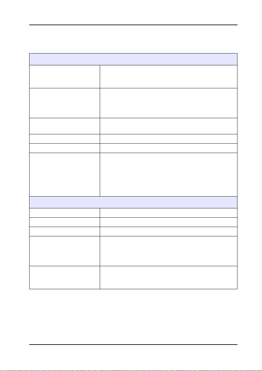
Kapitel 1 Spezifikationen
Änderungen vorbehalten!
Leistungsspezifikationen
Thermostat mit einem Heizblock bzw. zwei separaten
Typ
Temperaturprogramme
Zeitprogramme
Aufheizrate von 20 °C auf 148 °C in 10 min (nach DIN 38409-44)
Temperaturstabilität +/- 1 °C
Anzahl der Küvetten
Abmessungen des Messgeräts und Umweltbedingungen
Breite 250 mm
Höhe 145 mm
Tiefe 310 mm
Gewicht
Umweltbedingungen
Heizblöcken mit integrierten Schutzhauben zum
Erhitzen von Küvetten-Tests und Reaktionsgefäßen
CSB-Programm (148 °C, 120 min)
100 °C-Programm (100 °C, 30, 60, 120 min)
40 °C-Programm (40 °C, 10 min)
und frei wählbar 37–150 °C (keine Kühlung)
frei wählbar 0–480 min; akustisches Signal nach
Ablauf der Zeit
LTG082.xx.10xxx: 9 x 13 mm Durchmesser, 2 x 20
mm Durchmesser,
LTG082.xx.21xxx:
links: 15 x 13 mm Durchmesser,
rechts: 6 x 13 mm Durchmesser, 4 x 20 mm
Durchmesser
LTG 082.xx.10xxx : 2 kg Gerät,
3,5 kg incl. Verpackung
LTG 082.xx.21xxx : 2,8 kg Gerät,
4,3 kg incl. Verpackung
Arbeitstemperatur: 10–45 °C
Lagertemperatur: -40–60 °C
relative Feuchte: max. 90%, nicht kondensierend
9
Page 11

Spezifikationen
Weitere Technische Daten
Spannungsversorgung 115/230 V, +5%/-15%, 50/60 Hz, Schutzklasse I
Leistungsaufnahme
Sicherheitsprüfungen CE, GS und cTUVus
Garantie 2 Jahre
LTG 082.xx.10xxx : 115 V: 300 VA; 230 V: 450 VA
LTG 082.xx.21.xxx : 115 V: 600 VA; 230 V: 900 VA
10
Page 12

Kapitel 2 Allgemeine Informationen
2.1 Sicherheitshinweise
Lesen Sie die Bedienungsanleitung sorgfältig
und vollständig durch, bevor Sie das Gerät
auspacken, aufstellen und in Betrieb nehmen.
Achten Sie dabei besonders auf die
Sicherheitshinweise.
Damit die im Gerät vorgesehenen
Schutzvorrichtungen nicht beeinträchtigt
werden, darf das Gerät auf keinen Fall anders
installiert oder benutzt werden, als es in dieser
Bedienungsanleitung beschrieben ist.
2.1.1 Bedeutung von Gefahrenhinweisen
GEFAHR
Weist auf eine potenzielle oder
bevorstehende Gefahrensituation hin, deren
Nichtbeachtung zu ernsthaften V erletzungen
oder sogar zum Tod führen kann.
VORSICHT
Weist auf eine potenzielle Gefahrensituation
hin, deren Nichtbeachtung zu kleineren oder
mittelschweren Verle tzungen führen kann.
Wichtiger Hinweis: Geben dem Anwender
wichtige Informationen, auf die er bei der
Handhabung des Gerätes unbedingt achten
sollte.
Hinweis: Geben dem Anwender zusätzliche
Bedienungsinformationen.
11
Page 13
Allgemeine Informationen
2.1.2 Warnetiketten
Beachten Sie bitte die am Gerät angebrachten
Etiketten und Aufkleber. Bei Nichtbeachtung
dieser Warnetiketten können Personenschäden
oder Schäden am Gerät auftreten.
Wenn dieses Symbol am Gerät angebracht ist, sollte die
Bedienungsanleitung und/oder die Sicherheitshinweise beachtet werden.
In Übereinstimmung mit den örtlichen und nationalen gesetzlichen
Vorschriften (EU Richtlinie 2002/96/EC) übernimmt der Hersteller die
kostenlose Entsorgung von Altgeräten.
Hinweis: Eine Entsorgung über öffentliche Entsorgungssysteme ist ab
dem 13.08.2005 nicht mehr möglich. Bitte kontaktieren Sie für de n
Entsorgungsfall den Hersteller oder Ihren lokalen Ansprechpartner.
Dieses Symbol auf dem Gerät ist ein Hinweis auf heiße Oberflächen.
2.1.3 Gefahrenhinweise
12
GEFAHR
Die Lüftungsschlitze der Deckel dürfen nicht
abgedeckt sein, um einen ungehinderten
Temperat ur au sg leic h zu gewä h rle iste n.
Die Schutzdeckel müssen während des
Betriebs immer geschlossen sein.
Die Heizblöcke sind an der Oberfläche
wärmeisoliert.
Keinesfalls sollte jedoch mit den Fingern in die
Öffnungen gelangt werden,
Verbrennungsgefahr.
Der Thermostat LT 200 darf nur an einer
geerdeten Schutzkontaktsteckdose mit einem
unbeschädigten Netzkabel angeschlossen
werden.
Page 14

Allgemeine Informationen
2.2 Allgemeine Informationen
Der Thermostat ist nach dem neuesten Stand
der Technik und den anerkannten
sicherheitstechnischen Regeln konstruiert.
Der Hersteller bescheinigt, dass dieses Gerät
sorgfältig getestet und überprüft wurde und bei
Lieferung den angegebenen technischen Daten
entspricht.
Bei seiner Verw endung können unter
Umständen dennoch Gefahren für den
Anwender bzw. Beeinträchtigungen für das
Gerät entstehen.
2.3 Wichtige Instruktionen zur Bedienungsanleitung
Die Bedienungsanleitung enthält alle
notwendigen Angaben, um einen einwandfreien
Betrieb des Gerätes über die gesamte
Lebensdauer sicherzustellen.
Die Beachtung der Bedienungsanleitung
vermindert Ausfallzeiten und Reparaturkosten
und erhöht die Lebensdauer des Gerätes.
Urheberrechte
Das Urheberrecht an dieser
Bedienungsanleitung verbleibt bei dem
Hersteller.
Sie enthält Vorschri ften, Hinweise und
Zeichnungen technischer Art, die weder
vollständig noch teilweise
• vervielfältigt
• verbreitet
• zu Zwecken des Wettbewerbs unbefugt
verwertet oder
anderweitig mitgeteilt werden dürfen.
13
Page 15

Allgemeine Informationen
2.3.1 Brandschutzsicherheit
Bestimmte elektrische Schaltkreise in diesem
Gerät werden durch Sicherungen gegen
Überstromzustände (Überspannungen)
geschützt. Für den kontinuierlichen
Brandschutz gilt, Sicherungen nur durch
Sicherungen desselben Typs und derselben
Einstufung zu ersetzen.
2.3.2 Chemische und biologische Sicherheit
GEFAHR
Das Arbeiten mit chemischen Proben,
Standards und Reagenzien ist mit Gefahren
verbunden. Es wird dem Benutzer dieser
Produkte empfohlen, sich vor der Arbeit mit
sicheren Verfahrensweisen und dem
richtigen Gebrauch der Chemikalien vertraut
zu machen und alle entsprechenden Sicherheitsdatenblätter aufmerksam zu lesen.
Beim normalen Betrieb dieses Geräts kann der
Einsatz von toxischen oder ätzenden
Chemikalien erforderlich sein.
14
• Bitte beachten Sie die Gefahrenhinweise
zum Umgang mit dem entsprechenden
chemischen Stoff auf der Verpackung
desselben.
• Sämtliche verbrauchte Lösungen müssen in
Übereinstimmung mit den nationalen
Vorschrif t en un d Gesetzen ent s orgt werden .
Page 16

Allgemeine Informationen
2.4 Überblick Produkt/Funktionen
Der Thermostat LT 200 bietet die Möglichkeit,
Lösungen in Rundküvetten verschiedener
Größe auf 37–150 °C über einen Zeitraum von
0–480 Minuten, zu erhitzen.
Der Thermostat LT 200 ist mit einem oder mit
zwei separat temperierbaren Heizblöcken
ausgestattet.
Die kleinen Öffnungen im Heizblock mit 13 mm
Durchmesser sind zur Aufnahme der LANGE
Küvetten-Tests geeignet, z. B. CSB- und
Phosphat-Küvetten. Die großen Öffnungen mit
20 mm Durchmesser sind zur Aufnahme von
Reaktionsgläsern bestimmt. In den
Reaktionsgläsern wird die Probenvorbereitung,
z. B. der Aufschluss für einige Küvetten-Tests
durchgeführt.
Die aktuellen Temperaturen der Heizblöcke und
die Restzeiten werden im Digitaldisplay
permanent angezeigt.
Der Thermostat LT 200 ist mit 3 fest
vorgegebenen und 6 frei programmierbaren
Temperaturprogrammen ausgestattet.
Der Thermostat LT 200 unterstützt mehrere
Sprachen.
2.5 Entsorgung gemäß EU Richtlinie 2002/96/EC
Hinweise für die Vorber eitung eines
Elektrogerätes für die Entsorgung:
• eventuell noch vorhandene Küvetten aus
dem Gerät entfernen
15
Page 17

Allgemeine Informationen
16
Page 18

Kapitel 3 Installation
VORSICHT
Diese Bedienungsanleitung ist für das
Bedienungspersonal bestimmt und nur bei
strikter Beachtung dieser
Bedienungsanleitung können Unfälle
vermieden und ein störungsfreier Betrieb
des Gerätes gewährleistet werden.
3.1 Auspacken des Gerätes
1. Nehmen Sie den Thermostaten LT 200 und
die Zubehörteile aus der
Versandverpackung.
2. Schieben Sie keine losen Gegenstände
unter das Gerät, andernfalls besteht die
Gefahr, dass das Gerät nicht standfest ist.
3. Untersuchen Sie jedes Teil auf Schäden,
die beim Versand entstanden sein können.
4. Senden Sie bitte keine Geräte/Teile an den
Hersteller zurück, ohne diesbezügliche
Vereinbarungen getroffen zu haben.
17
Page 19
Installation
3.2 Front- und Rückansicht
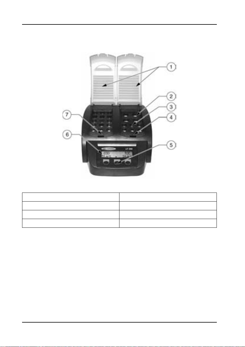
Abbildung 1 Frontansicht Thermostat LT 200
1 Schutzhauben 5 Funktionstasten
2 20 mm Aufschlussküvetten 6 Display
3 13 mm Küvetten-Tests 7 linker Heizblock
4 rechter Heizblock
18
Page 20
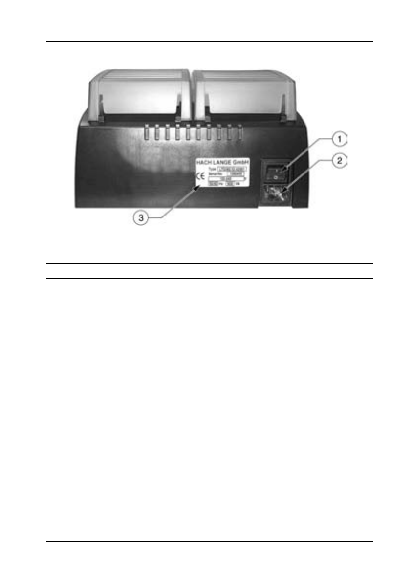
Abbildung 2 Rückansicht Thermostat LT 200
1 Ein/Aus Schalter 3 Typenschild
2 Buchse für Netzkabel
Installation
19
Page 21

Installation
20
Page 22
Kapitel 4 Software-Menü Übersicht
4.1 Software-Menü
AUSWAHL BLOCK
LINKS/RECHTS
AUSWAHL PROGRAMM
100 °
AUFSCHLUSSZEIT?
120’/60’/30
100 °C: 100 °C 60’
OK
AUSWAHL PROGRAMM
CSB
CSB: 148 °C 120’
OK
AUSWAHL PROGRAMM
40 °
40 °C: 40 °C 10’
OK
AUSWAHL PROGRAMM
PRG1
Auswahl des zu temperierenden Heizblockes.
Auswahl des 100 °C Temperatur Programms.
Erhitzt Küvetten 30, 60 oder 120 Minuten auf
100 °C.
Auswahl der Temperierungszeit.
Die Einstellung 100 °C, 60 Minuten wird z.B. bei
dem Aufschluss mit dem Crack Set LCW 902
benötigt. Programm mit
Auswahl des CSB Temperatur Programms. Erhitzt
Küvetten 2 Stunden auf 148 °C. In der
Abkühlphase zeigt ein vierfacher Beep-Ton an,
dass die Küvetten auf 80 °C abgekühlt sind.
Küvetten jetzt entnehmen und vorsichtig
schwenken, anschließend in einem
Küvettenständer abkühlen lassen.
Programm mit
Auswahl des 40 °C T emperatur Programms. Erhitzt
Küvetten 10 Minuten auf 40 °C.
Programm mit
Programmierung eines anwenderspezifischen
Temperaturprogramms
(5.4 Anwenderspezifische Temperaturprogramme
auf Seite 29).
OK starten.
OK starten.
OK starten.
21
Page 23

Software-Menü Übersicht
22
Page 24
Kapitel 5 Inbetriebnahme
5.1 Inbetriebnahme und Bedienung
Den Thermostaten auf eine stabile, ebene und
temperaturbeständige Unterlage stellen.
Das Stromkabel wird auf der Rückseite des
Thermostaten unterhalb des Kippschalters
eingesteckt und mit einer geerdeten
Netzsteckdose (115/230 Volt +5%/-15% /
50/60 Hz) verbunden.
Mit dem Kippschalter auf der Geräterückseite
wird das Gerät eingeschaltet.
Hinweis: Ein rasches Aus- und Einschalten ist zu
vermeiden. Vor einem erneuten Einschalten ca.
20 Sekunden warten, um die Elektronik und
Mechanik des Gerätes nicht zu beschädigen.
Wenn Sie das Gerät zum ersten Mal
einschalten öffnet sich die Liste zur Auswahl
einer Sprache automatisch (Kapitel 5.5 auf
Seite 30).
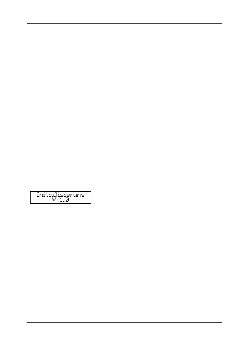
Nach einer Initialisierung ist das Gerät
betriebsbereit.
23
Page 25
Inbetriebnahme
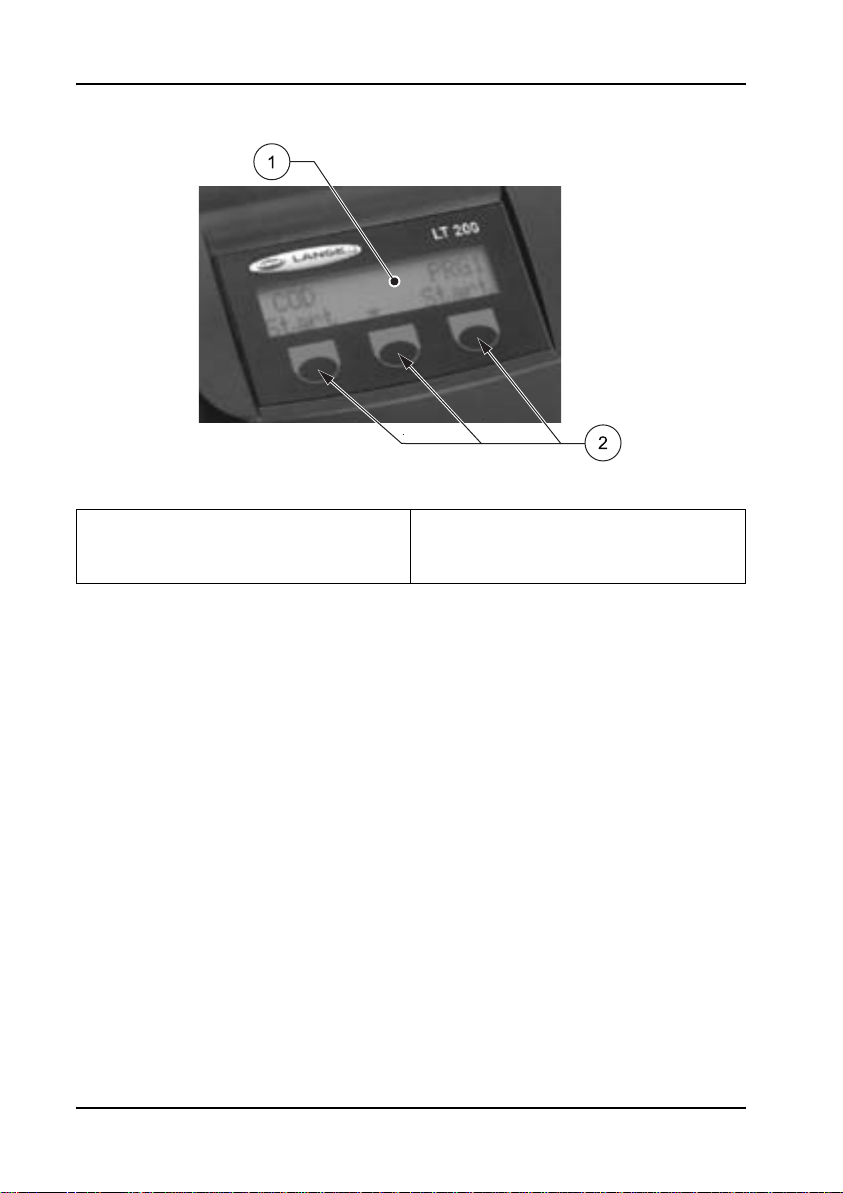
Abbildung 3 Display und Tasten Thermostat LT 200
1 Display 2 Funktionstasten (die jeweilige
Funktion wird im Display über den
Tasten angezeigt)
Die Bedienung des Thermostaten erfolgt über
drei Funktionstasten (Abbildung 3) unterhalb
des Displays. Die Bedeutung der Tasten
entsprechen der Displayanzeige direkt oberhalb
der Taste.
24
Wenn einer Taste keine Funktion zugeordnet ist,
ist die Taste im Moment nicht aktiv.
Das Display zeigt nach der Initialisierung immer
die letzte Einstellung der
Temper at ur pr ogramme an.
Page 26
5.2 Routinebetrieb
Inbetriebnahme
• Die Küvetten entsprechend der
Arbeitsvorschrift vorbereiten.
• Thermostat einschalten und Schutzhaube
öffnen.
• Küvetten in einen Heizblock einsetzen und
Schutzhaube schließen.
1. Gewünschtes Temperaturprogramm mit
den entsprechenden Tasten anwählen.
• Der Thermostat heizt auf die
eingestellte Temperatur, die Zeit läuft
automatisch auf Null zurück.
• Die aktuelle Temperatur und die
Restzeit werden permanent im Display
angezeigt.
• Ein dreifacher Beep zeigt das Ende des
Temperaturprogramms an, der
Thermostat kühlt ab.
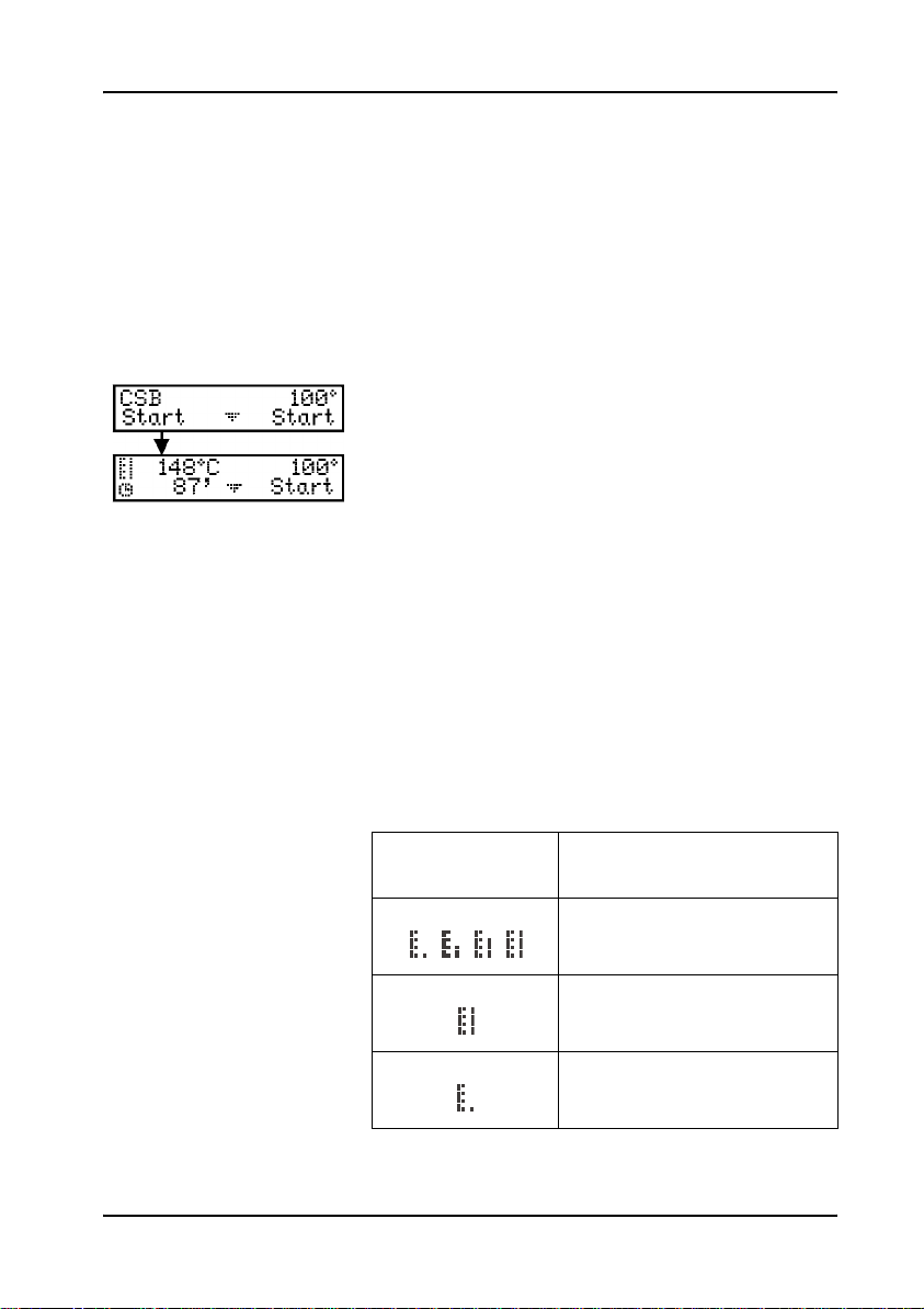
5.2.1 Thermometersymbol
Thermometersymbol
Beschreibung
Heizblock wird aufgeheizt.
Heizblock hat eingestellte
Temperatur erreicht.
Heizblock kühlt ab.
25
Page 27
Inbetriebnahme
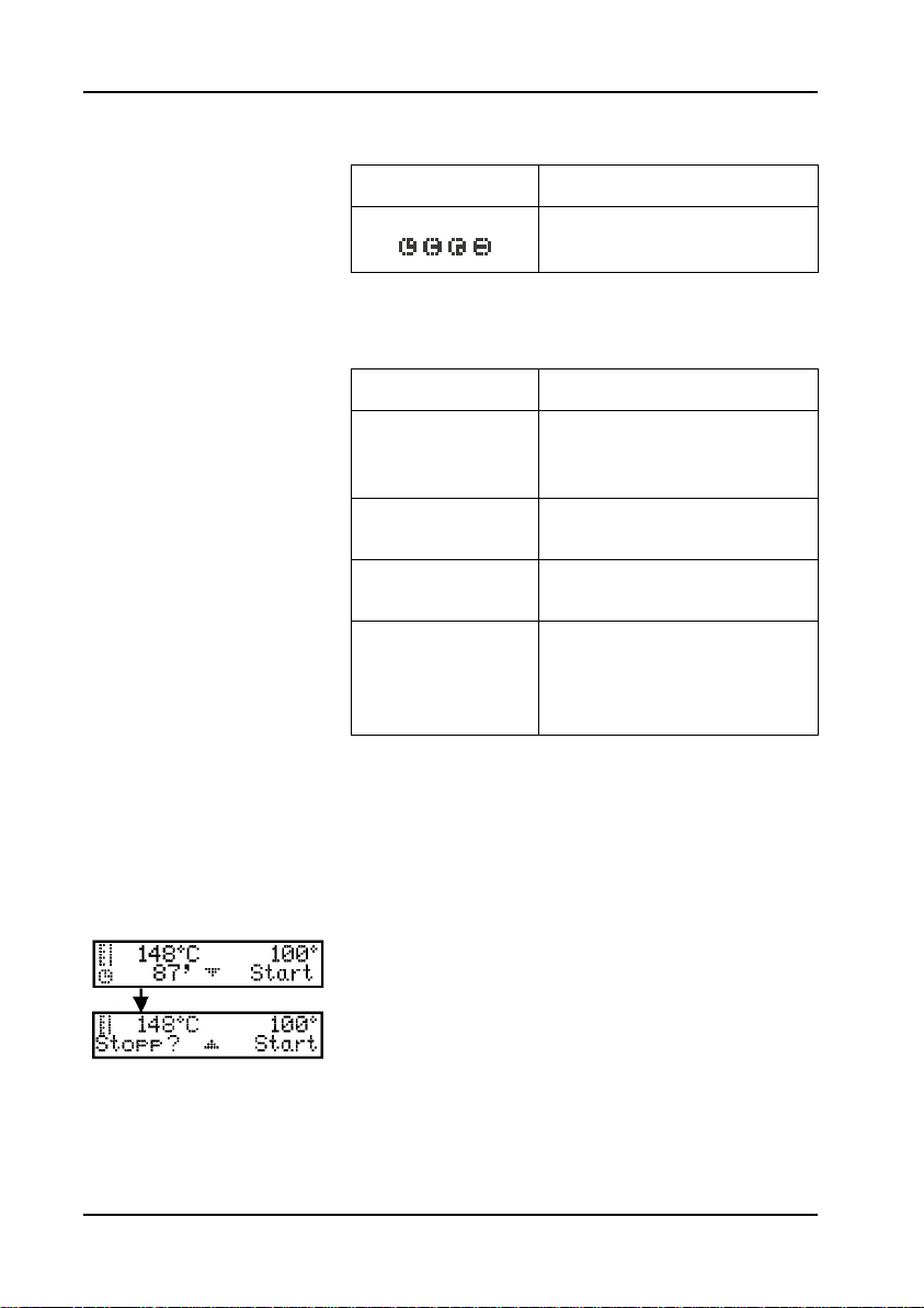
5.2.2 Uhrsymbol
5.2.3 Beep-Funktionen
Uhrensymbol Beschreibung
Restzeit läuft auf Null
zurück.
Beep-Funktion Beschreibung
Thermostat nach
1 x Beep
2 x Beep
3 x Beep
4 x Beep
Initialisierung
betriebsbereit.
Erreichen der eingestellten
Temperatur.
Ende des
Temperaturprogramms.
CSB-Programm,
Abkühlphase 80 °C.
Küvetten entnehmen und
schwenken.
5.2.4 Stopp-Funktion
26
Mit der Stopp-Funktion kann ein laufendes
Temperaturprogramm jederzeit abgebrochen
werden.
1. Das zu stoppende Programm anwählen.
2. Taste unter
Programm zu stoppen.
Hinweis: Die Taste unter PFEIL NACH OBEN führt das
Temperaturprogramm ohne Abbruch weiter.
STOPP anwählen, um das
Page 28
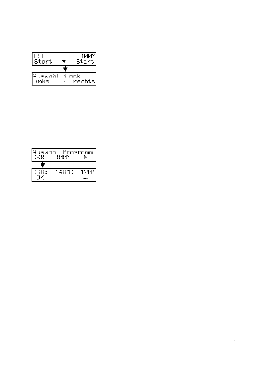
5.3 Programmauswahl
Die Auswahl der Temperaturprogramme ist
beim LT 200 mit zwei Heizblöcken für den
rechten und linken Heizblock völlig unabhängig.
Wird die Änderung der Einstellung aufgerufen
erfolgt zunächst die Auswahl, ob die Änderung
den linken oder rechten Heizblock betrifft.
Anschließend stehen 3 vorprogrammierte
Temperaturprogramme zur Verfügung, die mit
den entsprechenden Tasten unter den
Symbolen bzw. Beschreibungen aufgerufen
werden.
Das CSB-Programm erhitzt Küvetten 2 Stun den
auf 148 °C.
In der Abkühlphase zeigt ein vierfacher
Beep-Ton an, dass die Küvetten auf 80 °C
abgekühlt sind. Küvetten jetzt entnehmen und
vorsichtig schwenken. Diese Einstellung ist für
alle CSB Küvetten-Tests geeignet.
Inbetriebnahme
Hinweis: Drücken der Taste unter OK bestätigt die
Auswahl und drücken der Taste unter PFEIL NACH
führt zur Programmauswahl zurück.
OBEN
27
Page 29
Inbetriebnahme
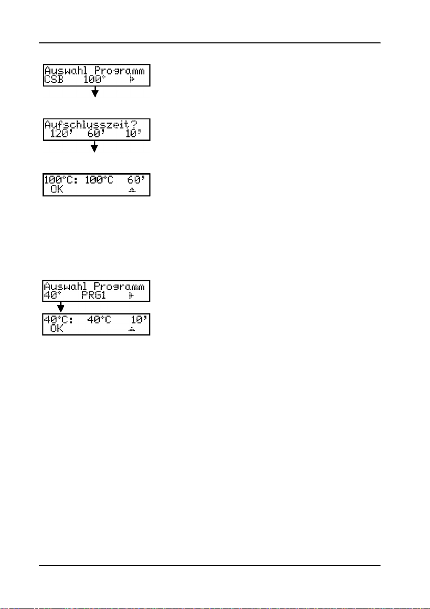
Das 100 °C-Programm erhitzt Küvetten 30, 60
oder 120 Minuten auf 100 °C.
Die Einstellung 100 °C, 60 Minuten wird z.B. bei
der Phosphat- und Chrombestimmung oder
zum Schwermetall-Aufschluss benötigt.
Hinweis: Drücken der Taste unter OK bestätigt die
Auswahl und drücken der Taste unter
OBEN
führt zur Programmauswahl zurück.
PFEIL NACH
Das 40 °C-Programm erhitzt Küvetten 10
Minuten lang auf 40 °C.
Diese Einstellung wird z.B. für enzymatische
Lebensmitteltests verwendet.
28
Hinweis: Drücken der Taste unter OK bestätigt die
Auswahl und drücken der Taste unter PFEIL NACH
OBEN
führt zur Programmauswahl zurück.
Page 30
Inbetriebnahme
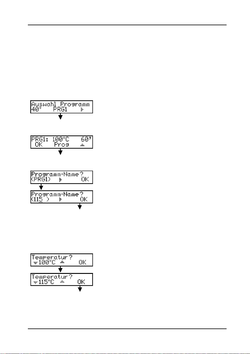
5.4 Anwenderspezifische Temperaturprogramme
Der Thermostat LT 200 bietet die Möglichkeit
6 i n div idu elle Temperaturprogramme unter den
Speicherplätzen PRG1 bis PRG6 abzulegen.
Beispielhaft wird im Folgenden die
Programmierung eines Temperaturprogrammes
erklärt:
1. Taste unter
2. Taste unter
3. Durch Drücken der Taste unter
PRG1 drücken.
PROG drücken.
PRG1 wird
ein 4-stelliger Programm-Name vergeben.
Durch mehrmaliges Drücken werden
Zahlen und Buchstaben durchlaufen.
Hinweis: Drücken der Taste unter PFEIL NACH
RECHTS
drücken der Taste unter
Eingabe.
rückt die Cursorposition weiter und
OK bestätigt die
4. Durch Drücken der Taste unter PFEIL NACH
UNTEN
bzw. PFEIL NACH OBEN wird die
Temperatur zwischen 37 °C und 150 °C
eingestellt.
Hinweis: Drücken der Taste unter OK bestätigt
die Eingabe.
29
Page 31

Inbetriebnahme
5. Durch Drücken der Taste unter PFEIL NACH
UNTEN
bzw. PFEIL NACH OBEN wird die Zeit
zwischen 0 und 480 Minuten eingestellt.
Hinweis: Drücken der Taste unter OK bestätigt
die Eingabe.
6. Durch Drücken der Taste unter OK wird die
Programmierung bestätigt.
Hinweis: Durch Drücken der Taste unter PROG
kann die Programmierung erneut verändert
werden.
5.5 Sprachauswahl
Soll die Menüsprache geändert werden, die
linke Taste während des Einschaltens gedrückt
halten.
Die rechte Taste unter
blättert durch das Sprachmenü.
Mit der entsprechenden Taste die gewünschte
Sprache auswählen .
Automatisch erfolgt die Initialisierung des
Thermostaten, anschließend ist das Gerät
betriebsbereit.
Hinweis: Drücken der Taste unter
OBEN
ruft erneut die Programmauswahl auf.
PFEIL NACH RECHTS
PFEIL NACH
30
Page 32

Kapitel 6 W artung
6.1 Reinigung des Gerätes
Der Thermostat ist ein wartungsfreies Gerät.
Für eine sichere und präzise Arbeitsweise ist es
notwendig, das Gerät sauber zu halten.
• Zur (äußerlichen) Reinigung Gerät
ausschalten, Netzstecker ziehen und
abkühlen lassen.
• Gerät mit einem weichen, mit Wasser
befeuchteten Tuch abwischen.
Es ist darauf zu achten, dass bei der Reinigung
keine Flüssigkeit in das Gerät eindringt!
Bei Überlaufen oder Platzen einer Küvette oder
Verkippen von geringen Mengen Flüssigkeit wie
folgt vorgehen:
• Thermostat ausschalten, Netzstecker
ziehen und abkühlen lassen.
• Flüssigkeit mit einer Pipette aus der
Bohrung absaugen, Hautkontakt
vermeiden.
GEFAHR
Bei Säuren und Laugen Gefahr der
Verätzung.
• Flüssigkeitsreste in eine leere Küvette
überführen und zur Entsorgung weiterleiten.
• Glassplitter mit einer Pinzette entfernen,
Hautkontakt vermeiden.
31
Page 33

Wartung
6.2 Geräteprüfung
Die im Display angezeigte Temperatur
entspricht der Temperatur, die in ein er mit einem
wässrigen Medium befüllten, geschlossenen
LANGE Küvette vorherrscht. Die reale
Blocktemperatur in der Nähe der Heizung kann
während der Heizphase höher sein als die im
Display angezeigte Temperatur.
Zur Überprüfung der Blocktemperatur wird eine
LANGE Leerküvette (LCW 906), Glycerin (ca.
5 ml) und ein geeichtes Stabthermometer
95 °C
–155 ° C (Typ 67C nach ASTM) benötigt.
• Die Küvette bei Raumtemperatur mit
Glycerin befüllen und Stabthermometer bis
auf den Boden der Küvette einsetzen.
• Die Füllhöhe des Glycerins muss incl.
Thermometer 62 mm +/- 0,5 mm betragen.
• Küvette in die mittlere Öffnung der zweiten
Reihe des zu prüfenden Blockes einsetzen.
• Anschließend das Temperaturprogramm
100 °C, 60 min für diesen Block starten.
Nach der Aufheizphase sollte die vom
Thermometer angezeigte Temperatur mit der
Anzeige im Display übereinstimmen.
6.3 Wechsel der Schutzhauben
Zum Wechseln der Schutzhauben gehen Sie
wie folgt vor:
1. Schutzhaube halb öffnen (ca. 45 °) und
oberhalb des außen liegenden Scharniers
anfassen wobei der Daumen in die
Schutzhaube greift (Abbildung 4).
32
Page 34

Wartung
2. Durch Druck mit dem Daumen auf die
Innenseite der Schutzhaube diese
vorsichtig etwas aufbiegen und nach vorne
aus der Halterung heben (Abbildung 5).
3. Anschließend die Schutzhaube etwas
anheben und die andere Seite aus der
Halterung entfernen.
4. Die Montage der neuen Schutzhaube
erfolgt in umgekehrter Reihenfolge.
Abbildung 4 Wechsel der Schutzhauben (Schritt 1)
Abbildung 5 Wechsel der Schutzhauben (Schritt 2)
33
Page 35

Wartung
34
Page 36

Kapitel 7 Fehler- bzw.
Displaymeldungen
BLOCK ZU HEIß!
BITTE WARTEN OK
INIT FEHLER
Die aktuelle Temperatur des Heizblocks ist höher
als die Soll-Temperatur. Bitte warten, bis de r
Heizblock abgekühlt ist.
Der Thermostat ist defekt. Bitte kontaktieren Sie
den Service.
35
Page 37

Fehler- bzw. Displaymeldungen
36
Page 38

Kapitel 8 Bestellhinweise
Bestellungen/Reparaturservice
Bitte wenden Sie sich an Ihre zuständige
Vertretung:
HACH LANGE GMBH
Willstätterstraße 11
D-40549 Düsseldorf
Tel. +49 (0 )2 11 5288-0
Fax +49 (0)2 11 5288-143
info@hach-lange.de
www.hach-lange.de
DR. BRUNO LANGE GES. MBH
Industriestraße 12
A-3200 Obergrafendorf
Tel. +4 3 (0)27 47 74 12
Fax +43 (0)27 47 42 18
info@hach-lange.at
www.hach-lange.at
DR. BRUNO LANGE AG
Juchstrasse 1
CH-8604 Hegnau
Tel. +41(0)44 9 45 66 10
Fax +41(0)44 9 45 66 76
info@hach-lange.ch
www.hach-lange.ch
37
Page 39

Bestellhinweise
Benötigte Angaben
• Nummer Ihres Kundenkontos (falls bekannt
bzw. vorhanden)
• Rechnungsanschrift
• Name und Tel.-Nr. des Anrufers
• Lieferanschrift
• Nr. der Bestellung
• Katalog-Nr.
• Kurzbeschreibung / Modell-Nr. des
Produkts/Serien-Nr.
• Menge
38
Page 40

Kapitel 9 Gewährleistung, Haftung
und Beanstandungen
Der Hersteller gewährleistet, dass das gelieferte
Produkt frei von Material- und
Verarbeitungsfehlern ist und verpflichtet sich,
etwaige fehlerhafte Teile kostenlos
instandzusetzen oder auszutauschen.
Die Verjährungsfrist für Mängelansprüche
beträgt bei Geräten 24 Monate. Bei Abschluss
eines Inspektionsvertrags innerhalb der ersten 6
Monate nach Kauf verlängert sich die
Verjährungsfrist auf 60 Monate.
Für Mängel, zu denen auch das Fehlen
zugesicherter Eigenschaften zählt, haftet der
Lieferer unter Ausschluss weiterer Ansprüche
wie folgt: Alle diejenigen Teile sind nach Wahl
des Lieferers unentgeltlich auszubessern oder
neu zu liefern, die innerhalb der V erjährung sfrist
vom Tage des Gefahrenüberganges an
gerechnet, nachweisbar infolge eines vor dem
Gefahrenübergang liegenden Umstandes,
insbesondere wegen fehlerhafter Bauart,
schlechter Baustoffe oder mangelhafter
Ausführung unbrauchbar werden oder deren
Brauchbarkeit erheblich beeinträchtigt wurde.
Die Feststellung solcher Mängel muss dem
Lieferer unverzüglich, jedoch spätestens 7 Tage
nach Feststellung des Fehlers, schriftlich
gemeldet werden. Unterlässt der Kunde diese
Anzeige, gilt die Leistung trotz Mangels als
genehmigt. Eine darüber hinausgehende
Haftung für irgendwelchen unmittelbaren oder
mittelbaren Schaden besteht nicht.
39
Page 41

Gewährleistung, Haftung und Beanstandungen
Sind vom Lieferer vorgegebene
gerätespezifische Wartungs- oder
Inspektionsarbeiten innerhalb der
Verjährungsfrist durch den Kunden selbst
durchzuführen (Wartung) oder durch den
Lieferer durchführen zu lassen (Inspektion) und
werden diese Vorgaben nicht ausgeführt, so
erlischt der Anspruch für die Schäden, die durch
die Nichtbeachtung der Vorgaben entstanden
sind.
Weitergehende Ansprüche, insbesondere auf
Ersatz von Folgeschäden, können nicht geltend
gemacht werden.
Verschleißteile und Beschädigungen, die durch
unsachgemäße Handhabung, unsichere
Montage oder nicht bestimmungsgerechten
Einsatz entstehen, sind von dieser Regelung
ausgeschlossen.
40
Page 42

DOC022.98.00742.JAN06
Thermostat LT 200
USER MANUAL (english)
January 2006, Edition 2
© Hach Lange GmbH, 2006. All rights reserved. Printed in Germany.
CK/SK
Page 43

42
Page 44

Table of Contents
Section 1 Specifications .................................................... 45
Section 2 General Information .......................................... 47
2.1 Safety Information ..............................................................47
2.1.1 Use of Hazard Information ........................................47
2.1.2 Precautionary Labels ................................................48
2.1.3 Warning .....................................................................48
2.2 General Product Information ..............................................49
2.3 Important information about the manual ............................49
2.3.1 Safety Against Risk of Fire ........................................50
2.3.2 Chemical and Biological Safety .................................50
2.4 Overview of Product/Function ............................................51
2.5 Disposal in accordance with EU directive 2002/96/EC ......51
Section 3 Installation ......................................................... 53
3.1 Unpacking the Instruments ................................................53
3.2 Front- and back view ..........................................................54
Section 4 Operation ........................................................... 57
4.1 Software Menu ...................................................................57
Section 5 Start up .............................................................. 59
5.1 Starting up ..........................................................................59
5.2 Routine operation ...............................................................61
5.2.1 Thermometer symbol ................................................61
5.2.2 Clock symbol .............................................................62
5.2.3 Beep functions ..........................................................62
5.2.4 Stop function .............................................................62
5.3 Selecting the program ........................................................63
5.4 User programs ...................................................................65
5.5 Language ...........................................................................66
Section 6 Maintenance ...................................................... 67
6.1 Cleaning the Instrument .....................................................67
6.2 Instrument test ...................................................................68
6.3 Changing the protective covers .........................................68
Section 7 Troubleshooting ................................................ 71
43
Page 45

Table of Contents
Section 8 Contact Information ...........................................73
Section 9 Warranty, liability and complaints ....................75
44
Page 46

Section 1 Specifications
Specifications are subject to change without
notice.
Performance Specific ations
Thermostat with one heating block or two separate
Type
Temperature programs
Timer programs
Heating rate from 20 °C to 148 °C in 10 min (to DIN 38409-44)
Temperature stability +/- 1 °C
Number of cuvettes
heating blocks with integrated protective lid for
heating cuvette tests and reaction vessels.
COD program (148 °C, 120 min)
100 °C program (100 °C, 30, 60, 120 min)
40 °C program (40 °C, 10 min)
and freely selectable 37–150 °C (no cooling)
freely selectable 0–480 min; acoustic signal when the
set time expires
LTG082.xx.10xxx: 9 x 13 mm diameter, 2 x 20 mm
diameter
LTG082.xx.21xxx:
left: 15 x 13 mm diameter
right: 6 x 13 mm diameter, 4 x 20 mm diameter
Physical and Environmental Specifications
Width 250 mm
Height 145 mm
Depth 310 mm
Weight
Ambient conditions
Additional technical data
Mains connection 115/230 V, +5%/-15%, 50/60 Hz, protection class I
Power input
Safety checks CE, GS and cTUVus
Guarantee 2 years
LTG 082.xx.10xxx : 2 kg instrument, 3.5 kg packed
LTG 082.xx.21xxx : 2.8 kg instrument, 4.3 kg packed
Operating temperature: 10– 4 5 °C
Storage temperature: -40–60 °C
Relative humidity: max. 90%, non-condensing
LTG 082.xx.10xxx : 115 V: 300 VA; 230 V: 450 VA
LTG 082.xx.21.xxx : 115 V: 600 VA; 230 V: 900 VA
45
Page 47

Specifications
46
Page 48

Section 2 General Information
2.1 Safety Information
Please read this entire manual before
unpacking, setting up, or operating this
equipment. Pay attention to all danger and
caution statements. Failure to do so could result
in serious injury to the operator or damage to
the equipment.
To ensure that the protection provided by this
equipment is not impaired, do not use or install
this equipment in any manner other than that
specified in this manual.
2.1.1 Use of Hazard Information
DANGER
Indicates a potentially or imminently
hazardous situation which, if not avoided,
could result in death or serious inju ry.
CAUTION
Indicates a potentially hazardous situation
that may result in minor or moderate injury.
Important Note: Information that requires
special emphasis.
Note: Information that supplements points in the
main text.
47
Page 49

General Information
2.1.2 Precautionary Labels
Read all labels and tags attached to the
instrument. Personal injury or damage to the
instrument could occur if not observed. A
symbol, if noted on the instrument, will be
included with a danger or caution statement in
the manual.
This symbol, if noted on the instrument, references the instruction manual
for operation and/or safety information.
Electrical equipment marked with this symbol may not be disposed of in
European public disposal systems after 12 August of 2005. In conformity
with European local and national regulations (EU Directive 2002/96/EC),
European electrical equipment users must now return old or end-of life
equipment to the Producer for disposal at no charge to the user.
Note: For return for recycling, please contact the equipment producer or
supplier for instructions on how to return end-of-life equipment,
producer-supplied electrical accessories, and all auxiliary items for proper
disposal.
This symbol, when noted on the product, indicated that the marked item
can be hot and should not be touched without care.
2.1.3 Warning
48
DANGER
The ventilation slits in the lid must not be
covered, otherwise overheating may occur.
The protective lids must always be closed
during operation.
The surface of the heating blocks is thermally
insulated. Never insert a finger into an opening,
as there is a danger of suffering burns.
The LT 200 thermostat should only be
connected to a socket outlet with earthing
contact. Be sure to use an undamaged cable.
Page 50

General Information
2.2 General Product Information
The thermostat has been designed in
accordance with the current state of the
technology and the acknowledged safety
regulations.
The manufacturer certifies that this instrument
was tested thoroughly, inspected and found to
meet its published specifications when it was
shipped from the factory.
Nevertheless, under certain circumstances
users may be at risk, or the proper functioning of
the instrument may be impaired.
2.3 Important information about the manual
The manual contains all the information needed
to enable the instrument to be operated without
any problems throughout its lifespan.
Such adherence results in less down-time and
lower repair costs, and increases the lifespan of
the instrument.
Copyright
The copyright to this User Manual remains with
the manufacturer.
The Manual contains instructions, notes and
drawings of a technical nature, which may not,
either in full or in part, be
• duplicated
• disseminated
• used without authorization for competitive
purposes or
communicated in any other way.
49
Page 51

General Information
2.3.1 Safety Against Risk of Fire
Certain electrical circuits within this equipment
are protected by fuses against over-current
conditions. For continued protection against a
risk of fire, replace fuses only with the same
type and rating specified.
2.3.2 Chemical and Biological Safety
DANGER
Handling chemical samples, standards and
reagents can be dangerous. Users of this
product are advised to familiarize
themselves with safety procedures and the
correct use of chemicals, and to carefully
read all relevant Material Safety Data Sheets.
Normal operation of this instrument may involve
the use of hazardous chemicals or biologically
harmful samples.
• The user must observe all cautionary
information printed on the original solution
containers and safety data sheet prior to
their use.
50
• All waste solutions must be disposed in
accordance with local and national law.
Page 52

General Information
2.4 Overview of Product/Function
The LT 200 thermostat can heat solutions in
round cuvettes of various sizes at 37–150 °C for
a period of 0–480 minutes.
The LT 200 thermostat has one
temperaturecontrolled heating block or two
separate ones.
The small openings (diameter 13 mm) in the
heating block are suitable for the HACH LANGE
cuvette tests, e.g. COD and phosphate
cuvettes. The larger openings (diameter 20 mm)
are intended for reaction vessels. Sample
preparation, e.g. the sample digestion for a
number of cuvette tests, is carried out in the
reaction vessels.
The actual temperatures of the heating blocks
and the remaining time are permanently visible
in the digital display.
The LT 200 thermostat has 3 permanent and 6
freely programmable temperature programs.
The LT 200 thermostat comes with a
multi-language support.
2.5 Disposal in accordance with EU directive 2002/96/EC
How to prepare an electrical instrument for
disposal:
• remove any cuvettes that are still in the
instrument
51
Page 53

General Information
52
Page 54

Section 3 Installation
DANGER
Only qualified personnel should conduct the
tasks described in this section of the
manual.
3.1 Unpacking the Instruments
1. Remove the LT 200 thermostat and
accessories from the shipping container.
2. Do not push any loose objects under the
instrument, as this could affect its stability.
3. Inspect each item for any damage that may
have occurred during shipment
4. Do not send the instrument back without
previous arrangement.
53
Page 55

Installation
3.2 Front- and back view
Figure 1 Front view of the LT 200 thermostat
1 Protective lid 5 Touch-sensitive Keys
2 20 mm digestion cuvettes 6 Display
3 13 mm cuvette tests 7 Left heating block
4 Right heating block
54
Page 56

Figure 2 Back view of the LT 200 thermostat
1 On/Off switch 3 Nameplate
2 Plug in power supply
Installation
55
Page 57

Installation
56
Page 58

Section 4 Operation
4.1 Software Menu
SELECT BLOCK
LEFT/RIGHT
SELECT PROGRAM
100 °
DIGESTION PERIOD?
120’/60’/30
100 °C: 100 °C 60’
OK
SELECT PROGRAM
COD
COD: 148 °C 120’
OK
SELECT PROGRAM
40 °
40 °C: 40 °C 10’
OK
SELECT PROGRAM
PRG1
Select the heating block.
Selection of 100 °C temperature program. Heats
cuvettes for 30, 60, or 120 minutes at 100 °C.
Selection of temperature time.
For example, the “100 °C, 60 minutes” setting is
needed to digest samples using the LCW 902
Crack Set. Start the program with
Selection of COD Temperatu r e program. Heats
cuvettes for 2 hours at 148 °C. In the cooling
phase, 4 beeps indicates that the cuvettes have
cooled to 80 °C. Remove and carefully invert the
cuvettes several times, before allowing them to
cool further in a rack.
Start the program with
Selection of 40 °C temperature program. Heats
cuvettes for 10 minutes at 40 °C.
Start the program with
Programming a user-specific temperature program
(5.4 User programs auf Seite 65).
OK.
OK.
OK.
57
Page 59

Operation
58
Page 60

Section 5 Start up
5.1 Starting up
Place the thermostats on a st able, level,
heat-resistant surface.
Plug one end of the power supply into the back
of the thermostat, below the power switch, and
plug the other into an earthed mains power
socket (115/230 Volt +5%/-15% / 50/60 Hz).
Switch on the thermostat by pressing the power
switch on the back.
Note: Do not switch the instrument off and on in rapid
succession. Always wait about 20 seconds before
switching the instrument on again, otherwise you may
damage the electronic and mechanical systems.
The first time the instrument is turned on, the
language selection screen will appear
(section 5.5 on page 66).
Start up
After initialization the instrument is ready for
operation.
59
Page 61

Start up
.
Figure 3 Display and Keys of the LT 200 thermostat
1 Display 2 Touch-sensitive Keys
The instrument is operated using three
touch-sensitive keys located below the display
(Figure 3). The function of the key depends on
the display.
60
If no function is shown for a specific key, that
key is not currently active.
After the instrument has been initialized, the
display always shows the most recent setting of
the temperature programs.
Page 62

5.2 Routine operation
• Prepare the cuvettes as described in the
working procedure.
• Switch on the thermostat and open the
protective lid.
• Place the cuvettes in a heating block and
close the protective lid.
1. Select the required temperature program
using the appropriate keys.
• The thermostat heats to the set temperature
and the time automatically counts down to
zero.
• The actual temperature and the re ma in ing
time are permanently visible in the display.
• Three beeps indicate that the temperature
program is finished; the thermostat cools.
Start up
5.2.1 Thermometer symbol
Thermometer
symbol
Description
Heating block is heating.
Heating block has reached
the set temperature.
Heating block is cooling.
61
Page 63

Start up
5.2.2 Clock symbol
5.2.3 Beep functions
Clock symbol Description
The remaining time counts
down to zero.
Beep function Description
Thermostat is ready for
1 beep
2 beeps
3 beeps
4 beeps
operation after
initialization.
Set temperature has been
reached.
End of temperature
program.
COD program - cooling
phase 80 °C - remove
cuvettes and invert a few
times.
5.2.4 Stop function
62
The stop function can be used to termina te a
temperature program at any time.
1. Select the program you want to stop.
2. Terminate the temperature program with
STOP.
Note: Press the UP ARROW KEY to allow the
temperature program to proceed without being
terminated.
Page 64

5.3 Selecting the program
The temperature programs can be selected
totally independently for the right and the left
heating blocks. If a change of setting is
selected, the user is prompted to specify
whether the change concerns the right or the left
heating block. A choice of 3 permanently
programmed temperature programs then
appears and the user selects one by pressing
the appropriate key.
The COD program heats cuvettes for 2 hours at
148 °C.
In the cooling phase, 4 beeps indicate that the
cuvettes have cooled to 80 °C. At this point, the
cuvettes must be removed and carefully
inverted a few times. This setting is suitable for
all COD cuvette tests.
Start up
Note: Press OK to confirm your selection or press the
UP ARROW KEY to return to the program selection
screen.
63
Page 65

Start up
The 100 °C program heats cuve ttes for 30, 60 or
120 minutes at 100 °C.
The setting “100°C, 60 minutes” is neede d, for
example, to determine phospha te an d
chromium or for digesting heavy metals.
Note: Press OK to confirm your selection or press the
UP ARROW KEY to return to the program selection
screen.
The 40 °C program heats cuvettes for
10 minutes at 40 °C.
This setting is used for, for example, enzymatic
food tests.
64
Note: Press OK to confirm your selection or press the
UP ARROW KEY to return to the program selection
screen.
Page 66

5.4 User programs
Start up
The LT 200 can accommodate 6 user programs
in the storage locations PRG1 to PRG6.
The following example illustrates how users can
program their own temperature programs:
1. Press key below
2. Press key below
3. Press
PRG1 to assign a 4-character
PRG1.
PROG.
program name. Press this key for several
times to run through the digits and letters.
Note: Press the RIGHT ARROW KEY to move the
cursor to the next position. Press OK to confirm
the entry.
4. Press the UP AND DOWN ARROW KEYS to
set the temperature to a value between
37 °C and 150 °C.
Note: Press OK to confirm the entry.
65
Page 67

Start up
5. Press the UP AND DOWN ARROW KEYS to
set the time to a value between 0 and 480
minutes.
Note: Press OK to confirm the entry.
6. Press OK to confirm the program.
Note: The program can be changed by pressing
PROG.
5.5 Language
Note: Press the
program selection screen.
UP ARROW KEY to return to the
If this setting needs to be changed, press the
left key while you switch on the instrument.
Press the
RIGHT ARROW KEY to scroll through
the menu.
Press the corresponding key to select the
required language.
The thermostat is automatically initialized and
the instrument is then ready for operation.
66
Page 68

Section 6 Maintenance
6.1 Cleaning the Instrument
The thermostat is a maintenance-free
instrument. To ensure reliable and precise
operation, it must be kept clean.
• Before cleaning the thermostat you should
switch it off, unplug the power cord and
allow the instrument to cool.
• Wipe the instrument with a soft, damp cloth.
Make sure that no water penetrates into the
instrument during cleaning!
If a cuvette overflows or bursts, or small
amounts of liquid are spilled, proceed as
follows:
• Switch off the thermostat, unplug the power
cord and allow the instrument to cool.
• Draw off the liquid with a pipette, avoiding
any contact with the skin.
DANGER
Caution should be exercised with acids and
lyes, as they can cause burns.
• Transfer liquid residues to an empty cuvette
for proper disposal.
• Remove broken glass with tweezers - avoid
any contact with the skin.
67
Page 69

Maintenance
6.2 Instrument test
The temperature shown in the display
corresponds to the temperature in a closed
LANGE cuvette filled with an aqueous medium.
During the heating phase, the real block
temperature in the vicinity of the heat er may be
higher than the temperature shown in the
display.
An empty LANGE cuvette (LCW 906), glycerol
(approx. 5 ml) and a stem-type thermometer
calibrated over the range from 95 °C
(type 67C to ASTM) are needed to check the
block temperature.
• Fill the cuvette with glycerol at room
• When the thermometer is in the cuvette, the
• Insert the cuvette in the centre opening of
–155 °C
temperature and insert the the rm o me te r
until it touches the bottom of the cuvette.
level of the glycerol must be 62 mm
+/- 0.5 mm.
the second row of the test block.
• Start the temperature program for 100 °C,
60 min for this block.
When the heating phase is complete, the
temperature shown by the thermometer should
be equal to the temperature shown in the
display.
6.3 Changing the protective covers
To change the protective covers, proceed as
follows:
1. Half open the protective cover (approx.
45 °) and take hold of it above the external
hinge with your thumb inside (Figure 4).
68
Page 70

Maintenance
2. Press your thumb against the inside of the
cover and carefully bend the cover upward
and lift it out of its mounting (Figure 5).
3. Lift the protective cover slightly and take the
other side out of the mounting.
4. Fit a new protective cover by carrying out
the above steps in the reverse order.
Figure 4 Changing the Protective lid (Step 1)
Figure 5 Changing the Protective lid (Step 2)
69
Page 71

Maintenance
70
Page 72

Section 7 Troubleshooting
BLOCK IS TOO HOT!
PLEASE WAIT OK
INIT ERROR
The temperature of the heating block is higher than
the target temperature. Wait until the heating block
cools.
The thermostat is defective. Please contact
Customer Service.
71
Page 73

Troubleshooting
72
Page 74

Section 8 Contact Information
Orders/Repair service
Please contact your representative:
HACH LANGE GMBH
Willstätterstraße 11
D-40549 Düsseldorf
Tel. +49 (0 )2 11 5288-0
Fax +49 (0)2 11 5288-143
info@hach-lange.de
www.hach-lange.de
HACH LANGE LTD
Pacific Way
Salford
Manchester, M50 1DL
Tel. +44 (0)161 872 14 87
Fax +44 (0)161 848 73 24
info@hach-lange.co.uk
www.hach-lange.co.uk
Information Required
• Hach account number (if available)
• Billing address
• Your name and phone number
• Shipping address
• Purchase order number
• Catalog number
• Brief description or model number or
series-production number
• Quantity
73
Page 75

Contact Information
74
Page 76

Section 9 Warranty, liability and
complaints
The manufacturer warrants that the product
supplied is free of material and manufacturing
defects and undertakes the obligation to repair
or replace any defective parts at zer o cost.
The warranty period for instruments is
24 months. If a service contract is taken out
within 6 months of purchase, the warranty
period is extended to 60 months.
With the exclusion of the further claims, the
supplier is liable for defects including the lack of
assured properties as follows: all those parts
that can be demonstrated to have become
unusable or that can only be used with
significant limitations due to a situation present
prior to the transfer of risk, in particular due to
incorrect design, poor materials or inadequate
finish will be improved or replaced, at the
supplier's discretion. The identification of such
defects must be notified to the supplier in writing
without delay, however at the latest 7 days after
the identification of the fault. If the customer fails
to notify the supplier, the product is considered
approved despite the defect. Further liability for
any direct or indirect damages is not accepted.
If instrument-specific maintenance and
servicing work defined by the supplier is to be
performed within the warranty period by the
customer (maintenance) or by the supplier
(servicing) and these requirements are not met,
claims for damages due to the failure to comply
with the requirements are rendered void.
Any further claims, in particular claims for
consequential damages cannot be made.
Consumables and damage caused by improper
handling, poor installation or incorrect use are
excluded from this clause.
75
Page 77

Warranty, liability and complaints
76
Page 78

DOC022.98.00742.JAN06
Thermostat LT 200
MODE D’EMPLOI (français)
Janvier 2006, Édition 2
© Hach Lange GmbH, 2006. To us droits réservés. Imprimé au Allemagne
CK/SK
Page 79

78
Page 80

Table des matières
Section 1 Caractéristiques ................................................ 81
Section 2 Introduction/Informations générales .............. 83
2.1 Consignes de sécurité .......................................................83
2.1.1 Utilisation des informations sur les dangers ..............83
2.1.2 Etiquettes de mise en garde .....................................84
2.1.3 Avertissement ...........................................................84
2.2 Informations générales ......................................................85
2.3 Importantes informations relatives au manuel ...................85
2.3.1 Sécurité contre les risques d’incendie .......................86
2.3.2 Sécurité chimique et biologique ................................86
2.4 Aperçu du produit/fonctions ...............................................87
2.5 Elimination conforme à la directive de l’UE 2002/96/EC ....87
Section 3 Installation ......................................................... 89
3.1 Déballage de l’appareil ......................................................89
3.2 Vues de face et de dos ......................................................90
Section 4 Menu .................................................................. 93
4.1 Software Menu ...................................................................93
Section 5 Mise en service ................................................. 95
5.1 Mise en service ..................................................................95
5.2 Utilisation courante ............................................................97
5.2.1 Symboles du thermomètrel .......................................97
5.2.2 Symbole de l'horloge .................................................98
5.2.3 Fonctions des signaux sonores .................................98
5.2.4 Fonction d'arrêt .........................................................99
5.3 Sélection du programme ....................................................99
5.4 Programmes utilisateur ....................................................101
5.5 Langue .............................................................................103
Section 6 Entretien .......................................................... 105
6.1 Nettoyage de l’instrument ................................................105
6.2 Test de l'instrument ..........................................................106
6.3 Remplacement des couvercles de protection ..................106
Section 7 Dépannage ....................................................... 109
79
Page 81

Table des matières
Section 8 Coordonnées des services à contacter .........111
Section 9 Garantie, responsabilité et réclamations ......113
80
Page 82

Section 1 Caractéristiques
Ces caractéristiques sont susceptibles d'être
modifiées sans avis préalable.
Caractéristiques de performance
Thermostat avec un bloc de chauffage ou deux blocs
Type
Programmes de
température
Programmes avec
minuterie
Vitesse de chauffage de 20 °C à 148 °C en 10 min (selon DIN 38409-44)
Stabi l it é d e temp éra ture +/- 1 °C
Nombre de cuves
Caractéristiques physiques et environnementales
Largeur 250 mm
Hauteur 145 mm
Profondeur 310 mm
Poids
Conditions ambiantes
de chauffage distincts avec couvercle de protection
intégré pour le chauffage de tests en cuve et de
récipients de réaction.
Programme DCO (148 °C, 120 mn)
Programme 100 °C (100 °C, 30, 60, 120 mn)
Programme 40 °C (40 °C, 10 mn)
et température programmable de 37 à 150 °C (sans
refroidissement)
programmable de 0 à 480 mn ; signal sonore au
terme de la durée définie.
L TG082.xx.10xxx: 9 x 13 mm de diamètre, 2 x 20 mm
de diamètre,
LTG082.xx.21xxx:
gauche : 15 x 13 mm de diamètre,
droit : 6 x 13 mm de diamètre, 4 x 20 mm de diamètre
LTG 082.xx.10xxx : 2 kg appareil seul,
3,5 kg emballé
LTG 082.xx.21xxx : 2,8 kg appareil seul,
4,3 kg emballé
Température de foncti onnement : 10 à 45 °C
Température de stockage : -40 à 60 °C
Humidité relative : 90% max., sans condensation
81
Page 83

Caractéristiques
Données techniques supplémentaires
Alimentation secteur
Puissance absorbée
Contrôles de sécurité CE, GS et cTUVus
Garantie 2 ans
115/230 V, +5%/-15%, 50/60 Hz, classe de
protection I
LTG 082.xx.10xxx : 115 V: 300 VA; 230 V: 450 VA
LTG 082.xx.21.xxx : 115 V: 600 VA; 230 V: 900 VA
82
Page 84

Section 2 Introduction/Informations
générales
2.1 Consignes de sécurité
Lisez la totalité du manuel avant de déballer,
installer ou utiliser cet appareil. Soyez
particulièrement attentif à toutes les précautions
et mises en garde afin d’éviter d’endommager
l’équipement ou de blesser gravement
l’opérateur.
Pour que la protection assurée par cet appareil
ne soit pas mise en péril, vous ne devez pas
l’installer ou l’utiliser d’une manière différente de
celle décrite dans ce manuel.
2.1.1 Utilisation des informations sur les dangers
DANGER
Signale une situation potentiellement
dangereuse ou un danger imminent qui, s’il
n’est pas évité, peut entraîner des blessures
graves ou fatales.
ATTENTION
Signale une situation potentiellement
dangereuse qui peut prov oq u e r de s
blessures légères ou sans gravité.
Remarque importante : Informations à prendre
en compte lors de la manipulation de
l’instrument.
Remarque : Informations d’utilisation
supplémentaires pour l’utilisateur.
83
Page 85

Introduction/Informations générales
2.1.2 Etiquettes de mise en garde
Lisez toutes les étiquettes apposées sur
l’appareil. En cas de non-respect, vous risquez
de vous blesser ou d’endommager l’appare il.
Ce symbole, s’il figure sur l’appareil, vous renvoie au manuel
d’instructions pour plus d’informations sur l’utilisation et/ou la sécurité.
Conformément aux réglementations locales et nationales en vigueur
(directive de l’UE 2002/96/EC), votre fabricant est tenu de prendre en
charge l’élimination gratuite des appareils usagés.
Remarque : A partir du 13 août 2005, la mise au rebut via les systèmes
d’élimination publics ne sera plus possible. Pour plus d’informations sur
vos problèmes d’élimination des déchets, contactez votre fabricant ou
votre distributeur.
Ce symbole, s'il figure sur l'appareil, indique la présence d'une surface
chaude.
2.1.3 Avertissement
DANGER
84
Les fentes de ventilation du couvercle ne
doivent pas pas être r ecouvertes, sous peine
d'engendrer une surchauffe.
Les couvercles de protection doivent toujours
être fermés pendant l'utilisation.
La surface des blocs de chauffe bénéficie d'un e
isolation thermique. N'insérez jamais le doigt
dans une ouverture, car vous risqueriez de
vous brûler.
Le thermostat LT 200 doit être exclusivement
raccordé à une prise secteur reliée à la terre.
Veillez à utiliser un câble qui n'est pas
endommagé.
Page 86

Introduction/Informations générales
2.2 Informations générales
Le thermostat a été conçu en accord avec l’état
actuel de la technologie et les règlements de
sécurité reconnus.
Le fabricant certifie que cet instrument, avant de
quitter l’usine, a été testé soigneusement,
vérifié et jugé conforme aux spécifications
publiées.
Dans certaines circonstances, toutefois,
l’utilisateur peut être exposé à des risques ou le
bon fonctionnement de l’appareil peut être mis
en péril.
2.3 Importantes informations relatives au manuel
Le manuel contient toutes les informations
requises pour faire fonctionner l’appareil sans
problème pendant toute sa durée de vie.
Ce respect des instructions réduit par ailleurs
les immobilisations et les frais de réparation,
mais prolonge aussi la durée de vie de
l’appareil.
Copyright
Les droits d’auteur de ce mode d’emploi
demeurent la propriété du fabricant.
Le mode d’emploi renferme des instructions,
remarques et schémas de nature technique qui
ne peuvent pas être partiellement ou totalement
• dupliqués
• disséminés
• utilisés sans autorisation à des fins de
concurrence ou
communiqués de toute autre manière.
85
Page 87

Introduction/Informations générales
2.3.1 Sécurité contre les risques d’incendie
Certains circuits électriques internes de cet
appareil sont protégés contre d’éventuelles
surtensions par des fusibles. Pour continuer à
protéger l’appareil contre les risques d’incendie,
remplacez les fusibles uniquement par des
fusibles de même type et possédant l’intensité
spécifiée.
2.3.2 Sécurité chimique et biologique
DANGER
La manipulation d’échantillons chimiques,
d’étalons et de réactifs peut être
dangereuse. Nous recommandons aux
utilisateurs de tels produits de se
familiariser avec les procédures de sécurité
et d’utilisation correctes des produits
chimiques, mais aussi de lire attentivement
toutes les fiches signalétiques des
matériaux appropriés.
86
L’utilisation normale de cet appareil peut
impliquer l’emploi de produits chimiques
dangereux ou d’échantillons nuisibles d’un point
de vue biologique.
• L’utilisateur doit respecter toutes les
informations de précaution imprimées sur
les conteneurs des solutions originales et
les fiches signalétiques avant tout usage.
• Toutes les solutions usées doivent être
éliminées conformément à la législation
locale et nationale en vigueur.
Page 88

Introduction/Informations générales
2.4 Aperçu du produit/fonctions
Le thermostat LT 200 peut chauffer des
solutions dans des cuves rondes de différentes
tailles à une température de 37 à 150 °C
pendant une période de 0 à 480 minutes.
Le thermostat LT 200 possède un bloc de
chauffage à régulation de température ou deux
blocs distincts.
Les petites ouvertures (13 mm de diamètre) du
bloc de chauffage sont adaptées aux tests en
cuve LANGE, notamment les cuves pour
phosphate et DCO. Les ouvertures plus
grandes (20 mm de diamètre) sont destinées
aux récipients de réaction. La préparation de
l’échantillon, par exemple la minéralisation
d'échantillon pour une série de tests en cuve,
s’effectue dans les récipients de réaction.
Les températures réelles des blocs de
chauffage et le temps restant sont visibles en
permanence sur l’affichage numérique.
Le thermostat LT 200 possède 3 programmes
de température fixe et 6 programmes de
température programmab le.
Le thermostat LT 200 est fourni avec un support
multilingue.
2.5 Elimination conforme à la directive de l’UE 2002/96/EC
Préparation d’un appareil électrique pour la
mise au rebut :
• retirez toutes les cuves encore présentes
dans l’appareil
87
Page 89

Introduction/Informations générales
88
Page 90

Section 3 Installation
ATTENTION
Il est destiné à être utilisé par le personnel
qui manipule l’appareil. Le fonctionnement
de l’appareil sans accident ou problème ne
peut être assuré qu’en respectant
scrupuleusement les instructions contenues
dans le manuel.
3.1 Déballage de l’appareil
1. Déballez le thermostat LT 200 et ses
accessoires.
2. Ne poussez aucun objet mobile sous
l’instrument, sous peine de compromettre
sa stabilité.
3. Vérifiez si aucun élément n’a été
endommagé pendant le transport.
4. Ne renvoyez pas l’appareil avant d’avoir
pris des dispositions.
89
Page 91

Installation
3.2 Vues de face et de dos
Figure 1 Vue avant du thermostat LT 200
1 Couvercle de protection 5 Touches
2 Cuves de digestion de 20 mm 6 Affichage
3 Tests en cuve de 13 mm 7 Bloc de chauffage gauche
4 Bloc de chauffage droit
90
Page 92

Figure 2 Vue arrière du thermostat LT 200
1 Interrupteur marche/arrêt 3 Plaque signalétique
2 Prise d’alimentation
Installation
91
Page 93

Installation
92
Page 94

Section 4 Menu
4.1 Software Menu
SÉLECTION BLOC
GAUCHE/DROITE
SÉLECTION PROGR.
100 °
TEMPS DÈSAGRÉG.
120’/60’/30
100 °C: 100 °C 60’
OK
SÉLECTION PROGR.
DCO
DCO: 148 °C 120’
OK
SÉLECTION PROGR.
40 °
40 °C: 40 °C 10’
OK
SÉLECTION PROGR.
PRG1
Sélectionnez le bloc de chauffage.
Sélectionnez le programme à 100 °C. Le
programme à 100 °C chauffe les cuves pendant 30,
60 ou 120 minutes à 100 °C.
Sélectionnez le tempérer de temps.
Par exemple, le réglage « 100 °C, 60 minutes » est
nécessaire pour digérer des échantillons en
utilisant le LCW 902 Crack Set. Appuyez la touche
OK pour exécuter le programme.
sous
Sélectionnez le programme à DCO. Le programme
DCO chauffe les cuves pendant 2 heures à 148 °C.
Lors de la phase de refroidissement, 4 signaux
sonores indiquent que les cuves ont été refroidies
jusqu'à une température de 80 °C.
Appuyez la touche sous
programme.
Sélectionnez le programme à 40 °C. Le programme
à 40 °C chauffe les cuves pendant 10 minutes à
40 °C.
Appuyez la touche sous
programme.
Programmation de programme de température
spécifiques à l’utilisateur.
(5.4 Programmes utilisateur à la page 101).
OK pour exécuter le
OK pour exécuter le
93
Page 95

Menu
94
Page 96

Section 5 Mise en service
5.1 Mise en service
Placez le thermostat sur une surface stable,
horizontale et résistante à la chaleur.
Connectez une extrémité du câble
d’alimentation à l’arrière du thermostat, sous la
prise d’alimentation, et branchez l’autre
extrémité sur une prise secteur mise à la terre
(115/230 Volts +5%/-15% / 50/60 Hz).
Mettez le thermostat sous tension en appuyant
sur l'interrupteur Marche/Arrêt situé au dos.
Remarque : Ne mettez pas l’appareil
successivement sous et hors tension rapidement.
Attendez toujours environ 20 secondes avant de
remettre l’appareil sous tension, sous peine
d’endommager les systèmes électroniques et
mécaniques.
L’écran de sélection de la langue s’affiche lors
de la mise sous tension initiale de l’instrument
(Section 5.5 à la page 103).
Une fois initialisé, l’instrument est prêt à
fonctionner.
95
Page 97

Mise en service
Figure 3 Affichage et touches du thermostat LT 200
1 Affichage 2 Touches à effleurement
Le thermostat est actionné à l’aide de trois
touches à effleurement situées sous l’affichage
(Figure 3). La fonction de chaque touche est
indiquée au-dessus, sur l’affichage.
96
Si aucune fonction n'est affichée pour une
touche particulière, cela signifie qu'elle n'est pas
active actuellement.
Une fois l'instrument initialisé, l'affichage
indique toujours le réglage le plus récent des
programmes de température.
Page 98

5.2 Utilisation courante
• Préparez les cuves comme décrit dans la
procédure d'utilisation.
• Mettez le thermostat sous tension et ouvrez
le couvercle de protection.
• Placez les cuves dans un bloc de chauffage
et refermez le couvercle de protection.
1. Sélectionnez le programme de température
requis à l'aide des touches appropriées.
• Le thermostat chauffe jusqu'à atteindre
• La température réelle et le temps
Mise en service
la température définie et le temps est
automatiquement décompté jusqu'à
zéro.
restant sont visibles en permanence sur
l'affichage.
• Trois signaux sonores indiquent la fin
du programme de température. Le
thermostat refroidit.
5.2.1 Symboles du thermomètrel
Symboles du
thermomètrel
Description
Le bloc de chauffage
chauffe.
Le bloc de chauffage a
atteint la température
définie.
Le bloc de chauffage
refroidit.
97
Page 99

Mise en service
5.2.2 Symbole de l'horloge
Symbole de
l'horloge
5.2.3 Fonctions des signaux sonores
Fonctions des
signaux sonores
1 x signal sonore
2 x signaux
sonores
3 x signaux
sonores
4 x signaux
sonores
Description
Le temps restant est
décompté jusqu'à zéro.
Description
Le thermostat est prêt à
fonctionner après
l'initialisation.
La température définie est
atteinte.
Fin du programme de
température.
Programme DCO, phase
de refroidissement à
80 °C, retirez les cuves et
inversez-les à plusieurs
reprises.
98
Page 100

5.2.4 Fonction d'arrêt
La fonction d'arrêt peut être utilisée pour mettre
fin à un programme de température à tout
moment.
1. Sélectionnez le programme à arrêter.
2. Mettez fin au programme avec la touche
sous
FIN.
Remarque : Appuyez la touche sous FLÉCHÉE HAUT
pour permettre au programme de température de se
poursuivre.
5.3 Sélection du programme
Les programmes de température peuvent être
sélectionnés de manière totalement
indépendante pour les blocs de chauffage droit
et gauche. Lorsque vous modifiez un réglage,
vous êtes invité à spécifier si la modification
concerne le bloc de chauffage droit ou gauche.
Une sélection de 3 programmes de températur e
fixe apparaît alors et l'utilisateur peut en
sélectionner un en appuyant sur la touche
appropriée.
Mise en service
99
 Loading...