

Page 1
DOC022.52.80021
User Manual
Luminescent Dissolved Oxygen Probe: Model LDO10101,
LDO10103, LDO10105, LDO10110, LDO10115 or LDO10130
Safety information
Precautionary labels
Read all labels and tags attached to the instrument. Personal injury or damage to the
instrument could occur if not observed. A symbol on the instrument is referenced in the
manual with a precautionary statement.
Electrical equipment marked with this symbol may not be disposed of in European public disposal systems after
12 August of 2005. In conformity with European local and national regulations (EU Directive 2002/96/EC), European
electrical equipment users must now return old or end-of-life equipment to the Producer for disposal at no charge to
the user.
Note: For return for recycling, please contact the equipment producer or supplier for instructions on how to return end-of-life
equipment, producer-supplied electrical accessories, and all auxiliary items for proper disposal.
Specifications
Note: Specifications are subject to change without notice.
Specifications Details
Probe type Luminescent dissolved oxygen (LDO) probe
Dissolved oxygen range 0.1 to 20.0 mg/L (ppm) 1 to 200% saturation
Dissolved oxygen accuracy ±0.1 mg/L for 0 to 8 mg/L
±0.2 mg/L for greater than 8 mg/L
% saturation resolution 0.1%
Stabilization time T90% at 10 seconds (when stirred)
Temperature resolution 0.1 °C (0.18 °F)
Temperature accuracy ±0.3 °C (±0.54 °F)
Pressure resolution 1 hPa
Pressure accuracy ±0.8%
Operating temperature range 0 to 50 °C (32 to 122 °F)
Storage temperature range 0 to 40 °C (32 to 104 °F)
Minimum sample depth 25 mm (0.984 in.)
Dimensions (standard) Diameter: 29 mm (1.14 in.)
Length: 191 mm (7.52 in.)
Cable length: 1 or 3 m (3.28 or 9.84 ft)
Dimensions (rugged) Diameter: 46 mm (1.81 in.)
Length: 223 mm (8.73 in.)
Cable length: 5, 10, 15 or 30 meter (16.40, 32.81, 49.21 or 98.42 ft)
Cable connection M12 digital output and connector compatible with HQd meters
Product overview
The LDO101 series probe is a luminescent dissolved oxygen probe (Figure 1). The
LDO10105, LDO10110, LDO10115 or LDO10130 rugged probe is available with a 5, 10,
15 or 30 m (16.40, 32.81, 49.21 or 98.42 ft) cable. The LDO10101 or LDO10103 standard
1
Page 2
probe is available with a 1 or 3 m (3.28 or 9.84 ft) cable and is intended for laboratory
use. The probe measures the dissolved oxygen concentration in wastewater, drinking
water and general applications.
Note: For BOD applications, use the LBOD10101 probe which has LDO technology and a stirrer.
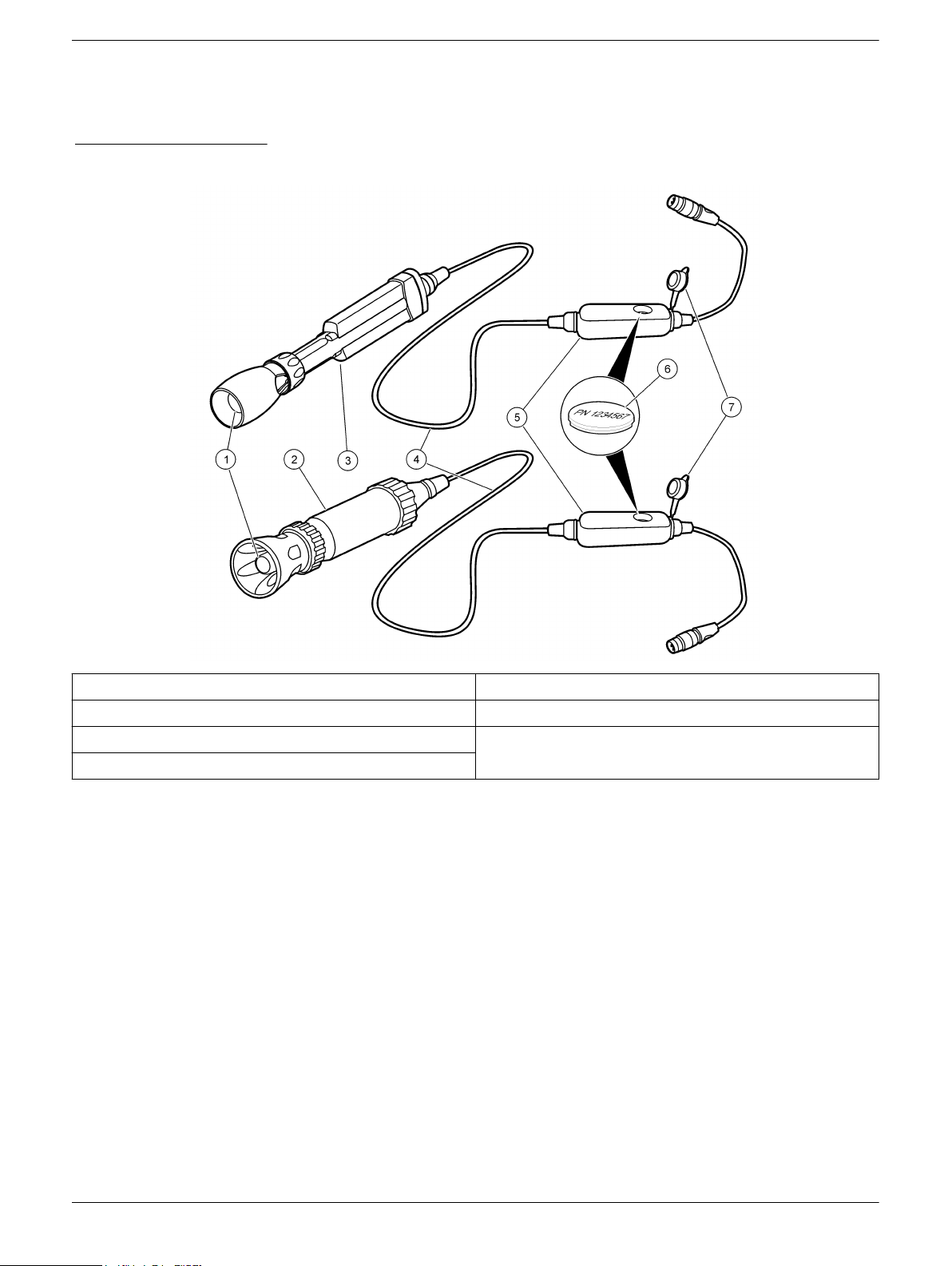
Figure 1 Probe overview
1 LDO probe cap 5 Pressure sensor module
2 Rugged probe (5, 10, 15 or 30 meter cable) 6 iButton® compartment
3 Standard probe (1 or 3 meter cable) 7 Pressure sensor module cap
4 Probe cable
1
iButton is a registered trademark of Maxim Integrated Products, Inc.
1
Preparation for use
Note: Do not touch the probe cap with a hand, fingers or any surface that can scratch the cap.
Prepare the probe for use before calibration or sample measurement.
1. Make sure that the probe cap and iButton are installed correctly. The iButton label
should be up.
2. Make sure that the probe cap and iButton have the same lot code.
3. If a rugged probe, make sure that the shroud is installed before field use (refer to
Install the shroud on page
Note: Damage to the sensing elements can occur if the shroud is not installed during field use.
Damage under these conditions is not covered by the product warranty.
4. Rinse the probe cap with deionized water. Blot dry with a lint-free cloth.
5. If dissolved oxygen monitoring periods are longer than 6 hours, condition the probe
cap for 72 hours. Calibrate the probe once every 8 hours.
Note: After 72 hours, the probe cap will reach a fully hydrated state.
9).
2
Page 3
Calibration
Before calibration:
The probe must have the correct service-life time stamp. Set the date and time in the meter before the probe is attached.
It is not necessary to recalibrate when moving a calibrated probe from one HQd meter to another if the additional meter is
configured to use the same calibration options.
To view the current calibration, push , select View Probe Data, then select View Current Calibration.
If any two probes are connected, push the UP or DOWN arrow to change to the single display mode in order to show the
Calibrate option.
Prepare the probe for use (refer to Preparation for use on page 2.
If a rugged probe, remove the shroud from the probe (refer to Remove the shroud on page 9).
Calibration notes:
•
% saturation or mg/L calibration methods are available in the Modify Current Settings
menu.
• The slope value is the comparison between the latest calibration and the factory
calibration shown as a percentage.
• An additional zero point calibration can be added to the calibration routine. Refer to
Change calibration options on page 8.
• The calibration is recorded in the probe and the data log. The calibration is also sent
to a PC, printer or flash memory stick if connected.
• Air bubbles under the sensor tip when submerged can cause slow response or error
in measurement. If bubbles are present, gently shake the probe until bubbles are
removed.
• If a calibration error occurs, refer to Troubleshooting on page 10.
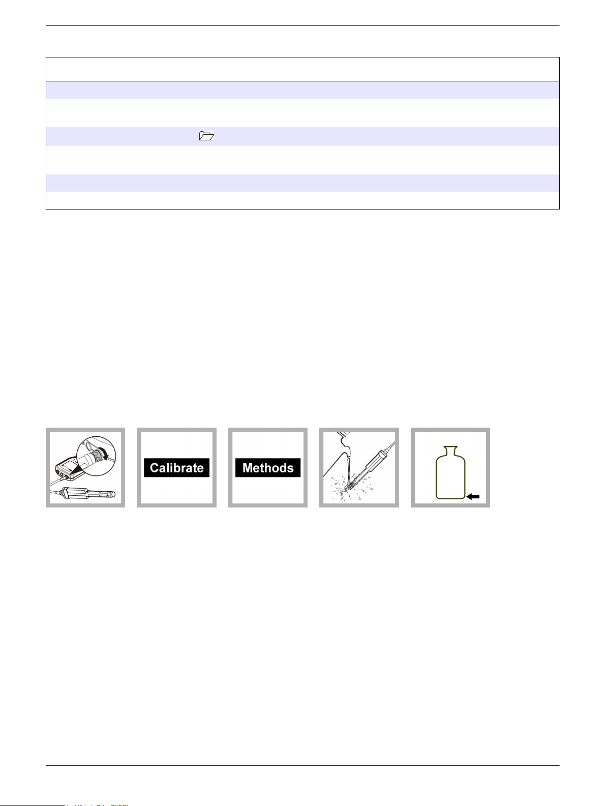
Water-saturated air (100%) calibration procedure:
1. Connect the
probe to the
meter. Make sure
that the cable
locking nut is
securely
connected to the
meter. Turn on the
meter.
2. Push
Calibrate.
3. Push
Methods. Select
User Cal - 100%.
Push OK.
4. Rinse the
probe cap with
deionized water.
Blot dry with a lintfree cloth.
5. Add
approximately ¼
inch (6.4 mm) of
reagent water to a
narrow-neck
bottle, such as a
BOD bottle.
3
Page 4
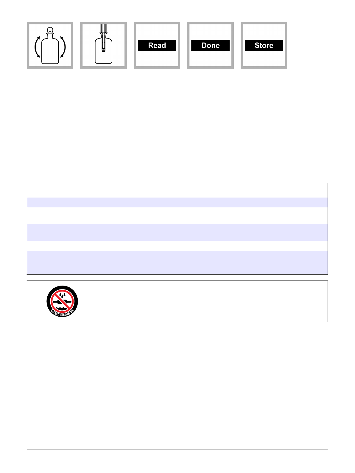
6. Put a stopper
in the bottle and
shake the bottle
vigorously for
approximately
30 seconds to
saturate the
entrapped air with
water. Allow up to
30 minutes for
contents to
equilibrate to room
temperature.
7. Remove the
stopper. Carefully
dry the probe cap
with a nonabrasive cloth. Put
the probe in the
bottle.
8. Push Read.
The display shows
"Stabilizing" and a
progress bar as
the probe
stabilizes. The
display shows the
standard value
when the reading
is stable.
9. Push Done to
view the
calibration
summary.
10. Push Store to
accept the
calibration and
return to the
measurement
mode. If a rugged
probe, install the
shroud on the
probe (refer to
Install the shroud
on page 9).
Sample measurement
Before measurement:
The probe must have the correct service-life time stamp. Set the date and time in the meter before the probe is attached.
If complete traceability is necessary, enter a sample ID and operator ID before measurement. Refer to the HQd meter
manual for more information.
Regular calibration is required for the best measurement accuracy (refer to Calibration on page 3). Calibrate the probe if
accuracy better than ±0.50 mg/L is necessary for the application.
Prepare the probe for use (refer to Preparation for use on page 2).
To deploy a rugged probe at a distance, toss the probe body with a gentle underhand throw. Do not swing the probe by the
cable as this may cause injury to the user, will cause severe strain on the cable and will shorten the service life of the cell.
Damage under these conditions is not covered by the product warranty.
Do not submerge the pressure sensor module.
Measurement notes:
•
Stabilization times with smaller concentration changes generally will be longer and
can be minimized by correct stirring and conditioning. Experiment to determine the
correct stir rate if necessary.
• Salinity affects the concentration of dissolved oxygen in the sample. To correct for
salinity effects, refer to Advanced operation on page 6 or do the Auto salinity
correction on page 5.
• Data is automatically stored in the data log when Press to Read or Interval is
selected in the Measurement Mode. When Continuous is selected, data will only be
stored when Store is selected.
• Air bubbles under the sensor tip when submerged can cause slow response or error
in measurement. If bubbles are present, gently shake the probe until bubbles are
removed.
• If a measurement error occurs, refer to Troubleshooting on page 10.
4
Page 5

Measurement procedure:
Note: Procedures also apply for rugged model probes.
1. Connect the
probe to the
meter. Make sure
that the cable
locking nut is
securely
connected to the
meter. Turn on the
meter.
2. Rinse the
probe cap with
deionized water.
Blot dry with a lintfree cloth.
Auto salinity correction
Dissolved substances affect the amount of oxygen water can hold. Manually enter salinity
settings for the most accurate dissolved oxygen measurements or use the optional Auto
Salinity Correction feature.
The manufacturer recommends using the Auto Salinity Correction feature when
measuring dissolved oxygen in samples where salinity varies. Auto salinity correction
measures dissolved oxygen through the connection of one LDO101 probe and one
CDC401 conductivity cell (set to Salinity parameter). The value obtained by the
CDC401 conductivity cell automatically adjusts the salinity value for the LDO101 series
probe. Salinity units are represented as parts per thousand (ppt) or (º/ºº).
3. Put the probe
in the sample and
stir gently or add a
stir bar. Do not put
the probe on the
bottom or sides of
the container. Stir
the sample at a
moderate rate or
put the probe in
flowing conditions.
4. Put the probe
in the sample at
least 25 mm
(0.984 in.) deep.
Push Read. The
display will show
"Stabilizing" and a
progress bar as
the probe
stabilizes in the
sample. The
display will show
the lock icon when
the reading
stabilizes.
5. Repeat steps
2-4 for additional
measurements.
When
measurements
are done, store
the probe Storage
on page 10.
1. Connect the LDO101 probe and CDC401 conductivity cell to the HQd meter. Turn the
meter on.
Note: Security options must be turned off to use auto salinity correction.
2. Push and select the CDC401 Settings.
3. Select Current Method, Hach Salinity. Push OK.
Note: To change more measurement options, choose Modify Current Settings, change the
parameter to Salinity and any other desired settings.
4. Push EXIT until the Full Access Options menu is shown.
5. Select LDO101 Settings, Modify Current Settings, Measurement Options, Salinity
Correction: Off. Then select Sal Correction Mode: Off. Push the DOWN arrow to
select Auto (*) - Use CDC401. Push OK.
6. Push EXIT until the meter returns to the measurement mode. The HQ40d meter is
now set up to automatically use the salinity values obtained by the CDC401 with the
LDO101 probe. If the salinity value is out of range, the display will show *S= ----
above the dissolved oxygen reading as shown in Figure 2.
Note: The asterisk (*) indicates that salinity is automatically correcting the dissolved oxygen
value. No asterisk indicates that salinity is being manually corrected. Warning messages will
override the asterisk (*) priority.
5
Page 6

Figure 2 Salinity value out of range
Advanced operation
Parameter-specific settings can be changed through the Full Access Options menu.
Details about menu navigation, available options and how to change them are given in
the screens, tables and procedures throughout this section.
The settings that can be changed are shown in Table 1.
Table 1 Parameter-specific settings
Setting Options Description
Measurement Options Resolution Defines measurement resolution
Measurement Limits Upper and lower measurement limits
Salinity Correction Value for salinity correction
Pressure Units Atmospheric pressure units
Averaging Interval How often the meter calculates an average readings
Units mg/L
%
Calibration Options Calibration
Calibration Reminder Reminder Repeat—Off, 8 h, 12 h, 1 d, 2 d, 5 d or 7 d
Primary unit of measurement
• User 100%
User 100% with 0
•
• User mg/L
• User mg/L with 0
• Factory
Expires—Immediately, Reminder + 30 m, Reminder + 1 h, Reminder + 2 h or
Continue Reading
Change measurement options
Methods are groups of default or user-defined settings relevant to specific applications. If
the meter is set to the default method and the Modify Current Settings option is chosen, a
prompt for a new name is shown after the changes are entered. The settings are saved
with this name to distinguish them from the default method settings, which cannot be
changed. A saved method can be used instead of multiple adjustments to the individual
settings. Changes made to a user defined method are automatically saved with the
existing name. Multiple methods can be saved for the same probe on each meter.
There are three default methods available for the LDO101 probe:
• Factory Cal (Calibration with default LDO calibration)
• User Calibration—100% (allows user calibration)
6
Page 7

• Default
1. Make sure a probe is connected to the meter.
2. Push and select LDO101 Settings.
3. Select Modify Current Settings.
4. Select Units. Select mg/L (default) or %.
5. Select Measurement Options and update the settings:
Option Description
Resolution Sets the resolution:
0.1—Fast (0.35 mg/L)/min
•
• 0.01—Fast (0.35 mg/L)/min
• 0.01—Medium (0.15 mg/L)/min (default), or
• 0.01—Slow (0.05 mg/L)/min
The resolution affects the number of decimal places and the stabilization
time. Higher resolution measurements take more time to stabilize.
Measurement
Limits
Salinity
Correction
Set the measurement limits—Lower limit (default: 0.0 mg/L; 0%) or Upper
limit (default: 20.0 mg/L; 200%).
The measurement limits can be set to match the acceptable values for the
sample. When the measurement is above the upper limit setting or below
the lower limit setting, the meter shows an "Out of limits" message. This
message is an alert to a potential problem with the process conditions.
Sets the salinity correction—Off (default), Manual or Auto (connect
conductivity probe).
Salinity lowers the solubility of dissolved oxygen in water. To correct for
salinity in the sample, set salinity correction to manual and then enter the
salinity value.
Note: When the HQ40d meter is used, a conductivity probe can also be
connected for automatic salinity measurement and correction. The
parameter setting for the conductivity probe must show salinity.
Salinity Value Sets the salinity value—‰ (default: 35.0 ‰).
When salinity correction is set to manual, sets the salinity value of the
sample. Salinity can be measured with a conductivity probe.
Pressure Units Sets the pressure units—hPa, mBar, inHg or mmHg.
The meter shows the atmospheric pressure at the current elevation, which
is necessary for accurate measurements.
Note: This pressure reading will not agree with readings from sources
such as weather stations, which report atmospheric pressure at sea level.
Averaging
Interval
Sets the averaging interval—Off, 30, 60, 90 seconds, 3, 5 minutes.
The averaging interval is useful for samples that contain a lot of air
bubbles, for example in an aeration basin. The air bubbles cause the
dissolved oxygen readings to vary greatly from one reading to the next. To
make the readings more consistent, increase the averaging interval. The
meter will take measurements at the same frequency but show only the
average over a longer interval.
Note: Labels and options may vary depending on the units selected.
6. If prompted, enter a name for the new method settings. Additional changes made to
the settings of an existing method are automatically saved with the same method
name.
7. Push EXIT until the meter returns to the measurement mode.
7
Page 8

Change calibration options
1. Make sure that a probe is connected to the meter.
2. Push and select LDO101 Settings.
3. Select Modify Current Settings.
4. Select Calibration Options and update the settings:
Option Description
Calibration
• User—100% (water-saturated air (100%) calibration)
User—100% with 0 (water-saturated air (100%) calibration with 0 point)
•
• User—mg/L (calibration with a specified dissolved oxygen concentration
(mg/L) solution)
• User—mg/L with 0 (calibration with a specified dissolved oxygen
concentration (mg/L) solution with 0 point )
• Factory (calibration with the default LDO calibration)
Maintenance
Clean the probe
Standard
Value
When Calibration is set to mg/L or mg/L with 0, sets the concentration of the
solution that will be used for calibration—2.00 to 20.00 mg/L
(default=7.00 mg/L)
5. Select Calibration Reminder and update the settings:
Option Description
Reminder
Repeat
Expires Calibration expires after the selected time—Immediately, Reminder +
Meter will make an audible sound when calibration is due and repeat the
sound at selected interval—Off, 8 h, 12 h, 1 d, 2 d, 5 d or 7 d.
30 min, Reminder + 1 h, Reminder + 2 h or Continue Reading.
Note: The meter cannot be used to read samples after calibration has
expired unless Continue Reading is selected.
6. If prompted, enter a name for the new method settings. Additional changes made to
the settings of an existing method are automatically saved with the same method
name.
7. Push EXIT until the meter goes back to the measurement mode.
Keep the probe cap free of deposits for the best measurements.
Note: Do not touch the black colored substrate of the probe cap. Do not use alcohol or other
organic solvents to clean the black colored substrate of the probe cap. These solvents cause
damage to the probe cap.
1. Remove the shroud (refer to Remove the shroud on page 9).
2. Gently clean the probe cap with a mild detergent, water and a soft cloth or cotton
swab. Do not remove the black colored substrate from the probe cap. Do not scrub
the probe cap or lens.
3. If water is present between the probe cap and lens:
a. Remove the probe cap.
b. Blot dry the probe cap and lens with a soft dry cloth.
c. Install the probe cap.
4. Install the shroud (refer to Install the shroud on page
9).
8
Page 9

Replace probe cap
The probe cap must be replaced every 365 days or more often if the cap becomes
damaged or fouled. The meter will show a reminder message when 30 days of probe
service life remains on the probe cap.
For LDO probe cap replacement instructions, refer to the instructions provided with the
LDO probe cap replacement kit.
Remove the shroud
1. Loosen and remove the locking ring (Figure 3).
2. Slide the shroud and locking ring off the probe.
Figure 3 Probe exploded view
1 Shroud 7 Probe lens
2 Locking ridges (8x) 8 Cap seal
3 Locking rib 9 Temperature sensor
4 Locking ring 10 Locking groove
5 Probe cap 11 Locking ribs (4x)
6 O-ring
Install the shroud
1. Put the locking ring on the probe with the threads toward the probe cap (Figure 3
on page
2. Slide the shroud on the probe until it is against the locking groove (rugged) or ribs
(standard). Slide the standard probe shroud on the standard probe until the inside
locking ridges align halfway between the ribs on the probe. Turn the shroud slightly
until it is seated.
3. Hand-tighten the locking ring on the shroud.
9).
9
Page 10

Storage
• Dry storage—the manufacturer recommends that the probe is stored dry when the
probe is used for measurements of short duration (less than 6 hours).
• Wet storage—the probe must be stored wet when the probe is used for monitoring
periods longer than 6 hours.
Dry storage
Note: Rugged probes may be stored dry with the shroud installed if the storage container is
sufficiently large.
1. Rinse the probe with deionized water. Blot dry with a lint-free cloth.
Note: The probe must be conditioned again in tap water for at least 30 minutes prior to use.
2. If a rugged probe, remove the shroud (optional). Refer to Remove the shroud
on page 9.
Wet storage
Note: The need for recalibration is minimized if the probe cap is kept wet.
1. Put the probe in tap water.
2. During the initial 72 hours in tap water, calibrate the probe once every 8 hours.
Note: After 72 hours of storage in tap water, the probe cap will reach a fully hydrated state.
Troubleshooting
Message or symptom Possible cause Action
Probe not supported Software not updated To download the most current version of the software,
refer to the applicable product page on the
manufacturer's website.
Refer to the HQd Series meter manual for specific
instructions for the meter model.
Connect a probe or probe requires
service
HQd meter does not support
IntelliCAL® probe
Probe not connected
correctly
Software not updated To download the most current version of the software,
Large number of methods
stored on the probe
Damaged probe Make sure there is connectivity with another probe or
Contact a Technical Support Representative.
Disconnect, then connect the probe. Tighten the locking
nut.
refer to the applicable product page on the
manufacturer's website.
Refer to the HQd Series meter manual.
Continue to let the probe connect. Do not disconnect the
probe.
meter to confirm isolated issue with probe. Contact a
Technical Support Representative.
10
Page 11

Message or symptom Possible cause Action
Out of range Probe cap loose, scratched
or damaged
Temperature and/or pressure
sensor error
Damaged probe Make sure that the blue and red LEDs are both
Sample outside of
specifications
iButton number does not
match probe cap lot number
Bubbles trapped under probe
tip
Out of range Probe cap exposed to direct
sunlight
Slope out of range Probe not prepared for
sample
Calibration method settings Make sure that the calibration standards in the method
Probe cap loose, scratched
or damaged
Reposition or replace the probe cap.
Make sure that the temperature and pressure sensors
are both reading correctly
1
.
illuminated on the probe. If not, replace the probe or
contact a Technical Support Representative.
Make sure that the sample concentration, temperature
and pressure are within the range of the probe.
Replace the iButton or probe cap or do a user
calibration.
Gently shake the probe until bubbles are removed.
Install the protective shroud.
Let the probe reach equilibrium in a water-saturated air
environment and do the calibration again.
are correct.
Locate and install the iButton that matches the probe
cap and replace the probe cap.
Temperature and pressure
errors
LED lights do not function Contact a Technical Support Representative.
Bubbles trapped under probe
tip
LDO–calibration not supported
(factory calibration)
LDO method calibration
option is set to Factory.
O2 Sensor 0 days remaining There are 0 days remaining
in the life of the probe cap
Meter set to incorrect date
and time
Software not updated Update the HQd software to the latest version and test
O2 Sensor ## of days remaining There are 30 days or fewer
remaining in the life of the
probe cap.
Make sure that the temperature and pressure sensors
are both reading accurately. Contact a Technical
Support Representative.
1
Gently shake the probe until bubbles are removed.
If user calibration is necessary, change the settings in
Calibration Options. Refer to Change calibration options
on page 8.
Replace the probe cap. Calibration will be allowed,
however the calibration icon and question mark will be
shown on the measurement screen even if the
calibration has passed.
Disconnect the probe from the meter. Set the correct
date and time in the Meter Options menu. Connect the
probe and make sure that the message has been
removed.
again.
Replace the probe cap soon.
11
Page 12

Message or symptom Possible cause Action
Calibration failed: outside of
acceptance criteria/Temperature
out of range/Offset out of limits
Water Saturated air
equilibration not reached
Probe cap loose, scratched,
or damaged
Temperature and/or pressure
sensor error
Allow longer equilibration time.
Change the location of the probe cap or replace the
probe cap.
Make sure that the temperature and pressure sensors
are both reading correctly and within range.
1
Damaged probe Make sure that the blue and red LEDs are both
illuminated on the probe. If not, replace the probe or
contact a Technical Support Representative.
1
The pressure as measured by the probe is what is referred to as atmospheric pressure and is not corrected to sea level.
Weather station pressures are reported at sea level and commonly referred to as mean sea level pressure. As a result the
probe will not read the same as most household or professional barometers or weather station reports (which are
compensated) unless reported at sea level. In order to compare the pressure results obtained from the probe barometer
and these compensated barometers, it is necessary to first compensate the pressure reported by the probes
mathematically.
HACH COMPANY World Headquarters
P.O. Box 389, Loveland, CO 80539-0389 U.S.A.
Tel. (970) 669-3050
(800) 227-4224 (U.S.A. only)
Fax (970) 669-2932
orders@hach.com
www.hach.com
©
Hach Company/Hach Lange GmbH, 2010, 2013. All rights reserved. Printed in U.S.A.
HACH LANGE GMBH
Willstätterstraße 11
D-40549 Düsseldorf, Germany
Tel. +49 (0) 2 11 52 88-320
Fax +49 (0) 2 11 52 88-210
info@hach-lange.de
www.hach-lange.de
HACH LANGE Sàrl
6, route de Compois
1222 Vésenaz
SWITZERLAND
Tel. +41 22 594 6400
Fax +41 22 594 6499
05/2013, Edition 2
 Loading...