

Page 1
User Manual
Fluoride Probe: Model ISEF12101 or ISEF12103
Safety information
Precautionary labels
Read all labels and tags attached to the instrument. Personal injury or damage to the
instrument could occur if not observed. A symbol on the instrument is referenced in the
manual with a precautionary statement.
Electrical equipment marked with this symbol may not be disposed of in European public disposal systems after
12 August of 2005. In conformity with European local and national regulations (EU Directive 2002/96/EC), European
electrical equipment users must now return old or end-of-life equipment to the Producer for disposal at no charge to
the user.
Note: For return for recycling, please contact the equipment producer or supplier for instructions on how to return end-of-life
equipment, producer-supplied electrical accessories, and all auxiliary items for proper disposal.
Specifications
Note: Specifications are subject to change without notice.
Specifications Details
DOC022.52
.80028
Probe type Digital combination probe with a non-refillable reference junction and a built-
in temperature sensor
Range 0.01 mg/L (5x10⁻⁷ M) to 19,000 mg/L (1 M) Fluoride
Sample pH range pH 4 to 8, must be adjusted to 5.0 to 5.5 by Fluoride ISA
Linear region 0.1 mg/L to 19,000 mg/L
Slope 59 mV/pF (90 to 110% at 25 °C (77 °F) in linear range per Nernstian
theoretical value)
Operating temperature range 5 to 50 °C (41 to 122 °F)
Storage temperature range 5 to 35 °C (41 to 95 °F)
Junction Single junction (annular porous Teflon®)
Reference type Ag/AgCl
Response time in linear region < 60 seconds (application dependent)
Minimum sample volume 25 mL
Minimum immersion depth 25.4 mm (1 in.)
Dimensions Diameter: 12 mm (0.47 in.)
Length: 175 mm (6.89 in.)
Cable length: 1 or 3 m (3.28 or 9.84 ft)
Cable connection M12 digital output and connector compatible with HQd meters
Product overview
The ISEF12101 or ISEF12103 probe is a combination fluoride
temperature sensor (Figure 1). The probe is available with a 1 or 3 m (3.28 or 9.84 ft)
cable and is intended for laboratory use. The probe measures fluoride concentration in
water samples.
probe with a built-in
1
Page 2
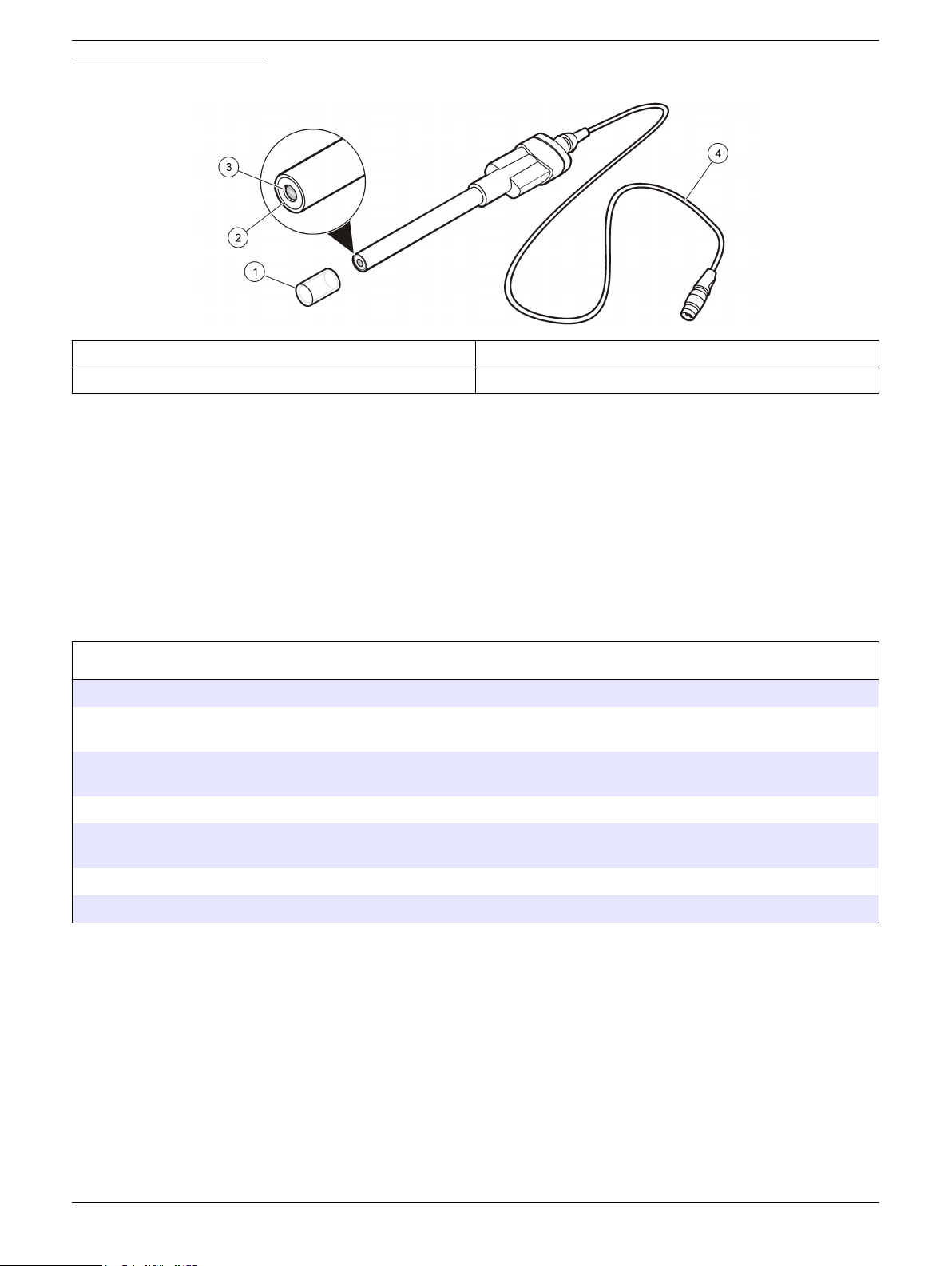
Figure 1 Probe overview
1 Sensor protection cap 3 Sensing element
2 Reference junction 4 1 or 3 m (3.28 or 9.84 ft) cable
Preparation for use
Prepare the probe for use before calibration or sample measurement.
1. Remove the sensor protection cap from the probe.
2. Rinse the probe with deionized water. Blot dry with a lint-free cloth.
Note: Prior to use, the probe must be conditioned for at least 30 minutes in 100 mL of the
lowest concentration standard solution in the calibration set.
If probe stabilization is slow after storage, condition the probe for up to one hour in 100 mL of
the lowest concentration standard solution in the calibration set.
Calibration
Before calibration:
The probe must have the correct service-life time stamp. Set the date and time in the meter before the probe is attached.
It is not necessary to recalibrate when moving a calibrated probe from one HQd meter to another if the additional meter is
configured to use the same calibration options.
Use the factory-set method for drinking water or pure water when applicable to the sample type. The factory-set methods are
optimized for concentration levels that are typical of the specified sample type. Refer to Advanced operation on page
To view the current calibration, push , select View Probe Data, then select View Current Calibration.
If any two probes are connected, push the UP or DOWN arrow to change to the single display mode in order to show the
Calibrate option.
Prepare the probe for use (refer to Preparation for use on page 2).
Use plastic containers during calibration and measurements. Glass containers can cause inaccurate measurements.
Calibration notes:
Stir the standards and samples at a slow and steady rate to prevent the formation of
•
a vortex.
• Additional standard sets along with the minimum number of calibration points can be
selected on the Calibration Options menu.
• Push Skip to omit a standard from the calibration routine. The display will not show
Skip until the minimum number of standards is met.
• Begin with the lowest concentration during calibration. This reduces carry-over
contamination to give the best results.
• Note the temperatures of the standards during calibration. Keep temperatures
between calibration standards within ±2 ºC for optimal results.
7.
2
Page 3
• The calibration is recorded in the electrode and the data log. The calibration is also
sent to a PC, printer or flash memory stick if connected.
Air bubbles under the sensor tip when submerged can cause slow response or error
•
in measurement. If bubbles are present, gently shake the probe until bubbles are
removed.
• If a calibration error occurs, refer to Troubleshooting on page 11.
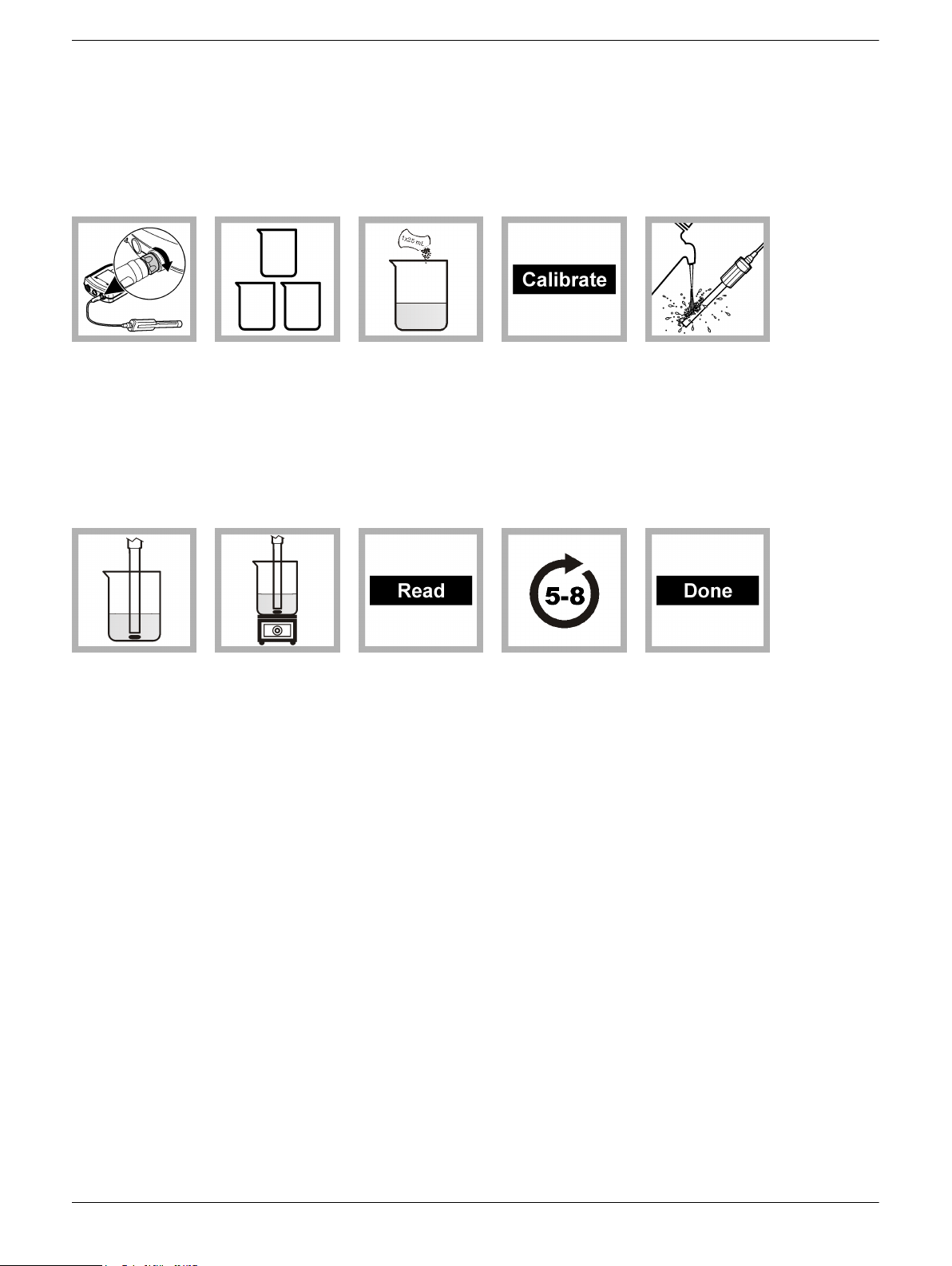
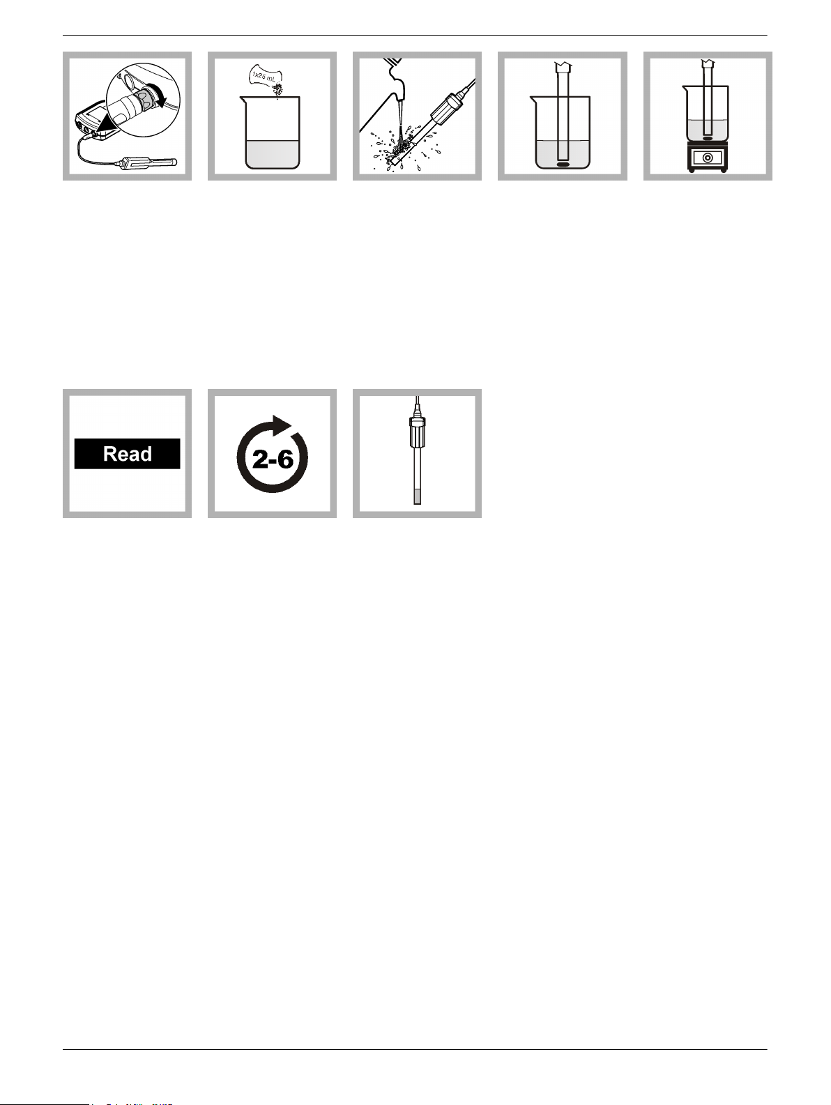
Calibration procedure:
1. Connect the
probe to the
meter. Make sure
that the cable
locking nut is
securely
connected to the
meter. Turn the
meter on.
6. Add a stir bar
and put the probe
in the first
standard solution
in the set. Do not
put the probe on
the bottom or
sides of the
container.
2. In three
separate beakers
or appropriate
containers,
prepare Fluoride
standard solutions
(minimum 25 mL
volume).
7. Put the beaker
on an
electromagnetic
stirrer and stir at a
moderate rate.
Check for air
bubbles and
remove them if
necessary.
3. Add the
contents of one
Fluoride ionic
strength
adjustment (ISA)
powder pillow per
25 mL to each
standard.
8. Push Read.
The display will
highlight the
standard value
and proceed to
the next standard
value. The display
will show
"Stabilizing" and a
progress bar as
the reading
stabilizes. The
display shows the
standard value
when the reading
is stable.
4. Push
Calibrate. The
display shows the
current standard
value that is to be
read from the
standard solution
set.
9. Repeat steps
5-8 for the other
Fluoride
solutions in the
set.
standard
5. Rinse the
probe with
deionized water.
Blot dry with a lintfree cloth.
10. Push Done to
view the
calibration
summary. The
display will not
show Done until
the minimum
number of
calibration points
have been
collected.
3
Page 4
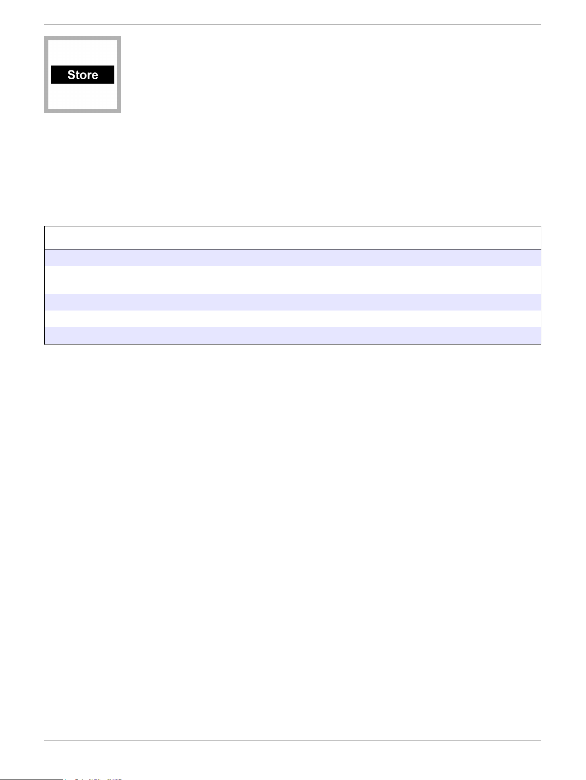
11. Push Store to
accept the
calibration and
return to the
measurement
mode.
Measurement—direct method
Before measurement:
The probe must have the correct service-life time stamp. Set the date and time in the meter before the probe is attached.
If complete traceability is required, enter a sample ID and operator ID before measurement. Refer to the HQd meter manual
for more information.
Regular calibration is required for the best measurement accuracy (refer to Calibration on page 2).
Prepare the probe for use (refer to Preparation for use on page 2).
Use plastic containers during calibration and measurements. Glass containers can cause inaccurate measurements.
Measurement notes:
•
Stir the standards and samples at a slow and steady rate to prevent the formation of
a vortex.
• Stabilization times with smaller concentration changes generally will be longer and
can be minimized by proper stirring and conditioning. Experiment to determine the
proper stir rate if necessary.
• The integrated temperature sensor and HQd meter software do not compensate for
differences in temperature between calibration standards and samples. Measurement
stabilization is not dependent on temperature stabilization. Temperatures of
calibration standards and samples should be kept within ±2 °C of each other for
optimal results.
• Data is automatically stored in the data log when Press to Read or Interval is
selected in the Measurement Mode. When Continuous is selected, data will only be
stored when Store is selected.
• Between measurements, rinse the probe with deionized water. Blot dry with a lint-free
cloth.
• Air bubbles under the sensor tip when submerged can cause slow response or error
in measurement. If bubbles are present, gently shake the probe until bubbles are
removed.
• If a measurement error occurs, refer to Troubleshooting on page 11.
Measurement procedure:
4
Page 5
1. Connect the probe
to the meter. Make
sure that the cable
locking nut is securely
connected to the
meter. Turn the meter
on.
2. Prepare a
minimum of 25 mL of
the sample(s) in
beakers or
appropriate
containers. Add the
contents of one
Fluoride ionic strength
adjustment (ISA)
powder pillow per
25 mL to each
sample.
3. Rinse the probe
with deionized water.
Blot dry with a lint-free
cloth.
4. Add a stir bar and
put the probe in the
sample. Do not put
the probe on the
bottom or sides of the
container.
5. Put the beaker on
an electromagnetic
stirrer and stir at a
moderate rate. Check
for air bubbles and
remove them if
necessary.
6. Push Read. The
display will show
"Stabilizing" and a
progress bar as the
probe stabilizes in the
sample. The display
will show the lock icon
when the reading
stabilizes.
7. Repeat steps 2 - 6
for additional
measurements.
Low-level measurements
Use the following techniques for measurements at low concentrations
• Use plastic containers during calibration and measurements. Glass containers can
cause inaccurate measurements.
• Clean the probe regularly as specified in Maintenance on page 10.
• Soak the probe in the lowest concentration standard solution for up to 1 hour before
calibration and measurement.
• Set the stability criteria to a low value (refer to Change measurement options
on page 7).
• Stir the standards and samples at a slow and steady rate to prevent the formation of
a vortex.
• Use a dilute ionic strength adjustor (ISA) solution for calibration and measurements:
8. When
measurements are
done, store the probe
(refer to Storage
on page
11).
(<1 mg/L F–).
1. Dissolve the contents of one ionic strength adjustor powder pillow in 50 mL of
deionized water.
2. Add 5 mL of this solution to every 25 mL of standard or sample that is used.
Note: The ionic strength adjuster can be omitted only when all of the following conditions are
true:
5
Page 6

Interferences
• The sample does not contain interferences.
The sample pH is in the range that is given in the specifications.
•
• Omission of the ISA is accepted by the regulatory reporting agency (if the measurement is
for regulatory reporting).
The sensing element responds to fluoride as well as other ions. Typically, probe response
to another ion increases the potential, and causes a positive error. The response to other
ions can be semi-quantitatively determined through the Nikolsky equation, an extended
Nernst equation:
E = Eº + (RT/(zF))ln[aNa + KNax × ax]
Where
• ax—the activity of the interfering ion
• KNax—the selectivity coefficient for the interfering ion relative to fluoride
Cations and most anions do not interfere with the ISEF121 probe response to fluoride
ions. Anions commonly associated with fluoride (Chloride (Cl-), Bromide (Br-), Sulfate
2-
(SO
), Bicarbonate (HCO
4
-
), Phosphate (PO
3
3-
) and acetate) do not interfere with probe
4
operation.
Hydroxyl ions (OH-) do interfere with probe response above pH 8. Some ions, such as
Carbonate (CO
2-
) or Phosphate (PO
3
3-
), make the sample more basic, which increases
4
Hydroxyl (OH-) interference, but do not directly interfere with the probe operation.
Hydroxide (OH-) ions interfere with the probe response to fluoride when the level of
hydroxide is greater than 10% of the level of fluoride present. At pH 8 or less, there are
no hydroxide ions to interfere. The error increases when the pH is increased and the
fluoride levels are decreased.
If Fluoride ISA is added to standards and samples, the pH is buffered between 5.0 and
5.5, which prevents hydroxide ion interferences.
The selectivity coefficient is the approximate apparent increase in the measured
concentration caused by one unit of the interfering ion (e.g., 1 unit of OH- raises the
fluoride concentration by 0.1). The approximate selectivity coefficients for some ions with
the IntelliCAL® Fluoride ISE are shown in Table 1.
Table 1 Interferences
Interference Selectivity coefficient
Hydroxyl (OH-) 0.1 (below pH 8)
Run a check standard
The run check standard feature validates instrument performance between sample
measurements. Use the run check standard feature for periodic or user-defined interval
measurements of a traceable standard solution. Set the criteria for check standards from
the ISEF121 Settings menu.
Note: Access control must be off or a valid password must be entered before any of the check
standard method options can be changed.
1. Push . The Full Access Options menu is shown.
2. Select Run Check Standard.
Note: Select the correct probe if two probes are connected to the meter.
3. Prepare the standard solution shown on the display. Add one powder pillow per
25 mL of standard solution.
4. Put the probe in the standard solution and push Read. The display will show
"Stabilizing" and a progress bar as the reading stabilizes. The display shows the
value of the check standard and either Check Standard Passed or Check Standard
Failed.
6
Page 7

5. If the display shows Check Standard Passed, the check standard measurement is
within the accepted limits set by the administrative user. Select Done to continue with
the sample measurement.
6. If the display shows Check Standard Failed, the measurement is outside of
accepted limits set by the administrative user and a recalibration is recommended. If
the acceptance criteria is set to Cal Expires on Failure: Yes, the display shows the
calibration icon and a question mark until the probe is recalibrated. To correct the
probe calibration and status indicator, calibrate the probe (refer to Calibration
on page
Advanced operation
Parameter-specific settings can be changed through the Full Access Options menu.
Details about menu navigation, available options and how to change them are given in
the screens, tables and procedures throughout this section.
The settings that can be changed are shown in Table 2.
2).
Table 2 Parameter-specific settings
Setting Options
Measurement Options
Calibration Options
Check Standard Options
• Units
• Significant digits
• Auto stabilization
• Stability criteria
• Upper and lower range limits
• Standard set
• Calibration units
• Minimum calibration points
• Slope limit
• Calibration reminder
• Standard
• Check standard reminder
• Acceptance criteria
Change measurement options
Methods are groups of factory-set or user-defined settings relevant to specific
applications. If the meter is set to a factory-set method and the Modify Current Settings
option is chosen, a prompt for a new name is shown after the changes are entered. The
settings are saved with this name to distinguish them from the factory-set methods, which
cannot be changed. A saved method can be used instead of multiple adjustments to the
individual settings. Changes made to a user-defined method are automatically saved with
the existing name. Multiple methods can be saved for the same probe on each meter.
7
Page 8

Setting Option Recommended range
Current method Pure water 0.1 to 1.0 mg/L F
Drinking water 0.5 to 2.0 mg/L F
Default >2.0 mg/L F
–
–
–
1. Make sure a probe is connected to the meter.
2. Push and select ISEF121 Settings.
3. Select Modify Current Settings.
4. Select Measurement Options and update the settings:
Option Description
Units Sets the preferred unit for ISE measurements—mg/L (default), µg/L, g/L,
g/kg, mol/L, mmol/L, mol/kg, %, ppm or ppb.
Note: The mV units are shown when the detailed display is selected.
Significant Digits Sets the significant digits shown—2, 3 (default) or 4.
Auto
Stabilization
Stability Criteria When Auto Stabilization is off, sets the stability criteria—0.1 to
Sets auto stabilization—on (default) or off.
The default stability drift rate is 1.0 mV/min.
9.9 mV/min.
Lower stability criteria will require longer stabilization times, but the
•
measurement will be more precise.
• Higher stability criteria will require shorter stabilization times, but the
measurements may be less precise.
• Stability criteria for factory-set methods: Pure water (0.2 mV/min),
Drinking water (0.4 mV/min); Default (1.0 mV/min).
Measurement
Limits
5. If prompted, enter a name for the new method settings. Additional changes made to
the settings of an existing method are automatically saved with the same method
name.
6. Push EXIT until the meter returns to the measurement mode.
Change calibration options
1. Make sure a probe is connected to the meter.
2. Push
3. Select Modify Current Settings.
Sets the measurement limits—Lower limit (default: 0.01 mg/L) or Upper
limit (default: 19,000 mg/L).
The measurement limits can be set to match the acceptable values for
the sample. When the measurement is above the upper limit setting or
below the lower limit setting, the meter shows an "Out of limits" message.
This message is an alert to a potential problem with the process
conditions.
and select ISEF121 Settings.
8
Page 9

4. Select Calibration Options and update the settings:
Option Description
Std Set Sets the temperature compensated standard sets that are used for
calibration—
0.5, 1 or 2 mg/L
•
• 1 or 10 mg/L
• 0.1, 1 or 10 mg/L
• 1, 10 or 100 mg/L
Standard set values are shown on the Calibration Options screen.
Custom standard sets are characterized at 25 °C (77 °F). Custom standard
values are not temperature compensated. Select the Custom buffer to
make a custom standard. Up to five standard values can be made .
Note: Only the minimum calibration points must be measured for Done to
be shown on the calibration screen.
Chemical Form Sets the chemical form.
Calibration
Units
Std Set Values When Std Set is set to Custom, sets the standard set values.
Minimum Cal
Points
Slope Limit Sets the slope limit—1 to 30% (acceptable slope criteria, default = 15%).
Sets the preferred unit for ISE Calibration—mg/L (default), µg/L (available
only for custom calibration set), g/L, g/kg, mol/L, mmol/L, mol/kg, %, ppm
or ppb.
Up to five standard values can be made. Each standard value can include
a standard set value, Custom or No Standard.
Sets the minimum number of calibration points necessary before a
calibration can be completed—2 or 3.
For factory-set methods, there are different slope limits: Pure water (slope
limit = 25%); Drinking water (slope limit = 15%); Default (slope limit =
15%).
The slope must fall within set limits for successful calibration.
5. Select Calibration Reminder and update the settings:
Option Description
Reminder
Repeat
Expires Calibration expires after the selected time—Immediately, Reminder + 30 min
6. If prompted, enter a name for the new method settings. Additional changes made to
the settings of an existing method are automatically saved with the same method
name.
7. Push EXIT until the meter returns to the measurement mode.
Change check standard options
1. Make sure a probe is connected to the meter.
2. Push and select ISEF121 Settings.
3. Select Modify Current Settings.
4. Select Check Standards Options and update the settings:
Option Description
Standard Sets the check standard—0.5, 1.0 (default), 2.0, 10.0 mg/L or Custom.
Meter will make an audible sound when a calibration is due and repeat the
sound at the selected interval—Off (default), 2 h, 4 h, 8 h, 2 d, 5 d or 7 d.
(default), Reminder + 1 h, Reminder + 2 h or Continue Reading.
Note: The meter cannot be used to read samples after calibration has
expired unless Continue Reading is selected.
The standard value is shown on the Check Standards Options screen.
9
Page 10

Option Description
Standard Units When Standard is set to Custom, sets the preferred unit for ISE check
standard—mg/L (default), µg/L, g/L, g/kg, mol/L, mmol/L, mol/kg, %, ppm or
ppb.
Standard Value When Standard is set to Custom, enter the standard value using the
up/down arrow keys.
5. Select Check Standard Reminder and update the settings:
Option Description
Reminder Sets the check standard reminder—On or Off (default).
The meter automatically shows the check standard screen if Reminder is On.
Allow Defer Allows the postponement of check standard reminders—Yes or No.
Measurement of the check standard can be delayed if Allow Defer is set to Yes.
6. Select Acceptance Criteria and update the settings:
Option Description
Acceptance Limits Sets the tolerance limits for check standard—1% to 20%.
Cal Expires on Failure Recalibration required if check standard fails—Yes or No.
The calibration expires if the check standard fails and Cal Expires is
set to Yes.
7. If prompted, enter a name for the new method settings. Additional changes made to
the settings of an existing method are automatically saved with the same method
name.
8. Push EXIT
until the meter returns to the measurement mode.
Maintenance
Clean the probe
Clean the probe when:
• Drifting/inaccurate readings occur as a result of contamination on the sensing
element or improper storage conditions.
• Slow response time occurs as a result of contamination on the sensing element.
• The slope is out of range as a result of contamination on the sensing element.
For general contaminants, complete the following steps.
1. Rinse the probe with deionized water. Blot dry with a lint-free cloth.
2. If harsh contaminants are attached to the probe, use a small amount of plain fluoride
toothpaste (no teeth whiteners or abrasives) and gently rub it into the crystal with a
circular motion. Continue to rub until the toothpaste film is removed. When finished,
rinse with deionized water to clean the probe.
3. Soak for 30 minutes in 1 mg/L Fluoride standard solution.
10
Page 11

Storage
The probe can be stored dry. To protect the sensing element, rinse with DI water and blot
dry with a lint-free cloth. Install the sensor protection cap.
Note: The probe must be conditioned after long-term storage. Refer to Preparation for use
on page 2.
Troubleshooting
Message or symptom Possible cause Action
Software not updated To download the most current version of the
software, refer to the applicable product page on the
manufacturer's website.
Probe not supported
Refer to the HQd Series meter manual for specific
instructions for the meter model.
Connect a probe or probe
requires service
mV reading is the same for all
solutions
Slow response time
HQd meter does not support
IntelliCAL® probe
Probe not connected properly Disconnect, then connect the probe. Tighten the
Software not updated To download the most current version of the
Large number of methods stored
on probe.
Damaged probe Make sure connectivity with another probe or meter
Electrical issue Contact a Technical Support Representative.
Dirty sensing element Clean the probe (refer to Clean the probe
Low sample temperature or
temperature difference between
samples
Bubbles trapped under sensor tip Gently shake the probe until bubbles are removed
Contact a Technical Support Representative.
locking nut.
software, refer to the applicable product page on the
manufacturer's website.
Refer to the HQd Series meter manual.
Continue to let probe connect. Do not disconnect
probe.
to confirm isolated issue with probe. Contact a
Technical Support Representative.
on page
Check the sample temperature. The lower the
temperature or the greater the difference of
temperatures between samples, traditionally the
longer the response time.
from under sensor tip.
10).
Slope out of range (refer to
Check probe response
on page 13)
pH is incorrect Make sure the pH is between 5.0 and 5.5 after each
ISA addition.
Ionic strength adjustor (ISA) not
used
Insufficient conditioning Condition for at least 30 minutes in a 0.1 mg/L
Damaged probe Contact a Technical Support Representative.
Incorrect standards Calibrate using freshly prepared standards.
Dirty sensing element Clean the probe and recalibrate.
Bubbles trapped under sensor tip Gently shake the probe until bubbles are removed
Add ISA to each sample and standard (one powder
pillow per 25 mL of solution).
standard solution with ISA.
from under sensor tip.
11
Page 12

Message or symptom Possible cause Action
Dirty sensing element Clean the probe (refer to Clean the probe
on page
Clogged reference Rinse reference junction with deionized water
thoroughly and shake the probe downward to
remove any air bubbles. The air bubbles will not be
visible.
Improper storage conditions Clean or condition the probe and attempt another
calibration. To re-condition the probe and reference
junctions, allow the probe to soak in a conditioning
solution (that contains ISA) for at least 30 minutes
prior to use.
10).
Drifting/inaccurate readings
Out of range Measurement value is outside of
Out of limits
Stabilization criteria not optimized
for the application
Magnetic stirrers may generate
sufficient heat to change solution
temperature.
Damaged probe Contact a Technical Support Representative.
Electromagnetic Forces (EMF)
such as voltaic cells, thermoelectric
devices, electrical generators,
resistors and transformers
Bubbles trapped under sensor tip Gently shake the probe until bubbles are removed
range
Check standard value is outside of
limits set in the current method
Measurement value is outside of
measurement limits set in the
current method.
Adjust the stabilization criteria in the measurement
options menu.
Put a piece of insulating material between the stirrer
and beaker.
Do not use in areas where EMF is present.
from under sensor tip.
Make sure that the sample is within the range of the
probe.
Make sure that the standard is within the limits of the
current method.
Make another method that expands the acceptable
limits.
Make sure that the sample is within the limits of the
current method.
Make a new method with an expanded range.
Temperature out of range
12
Calibration temperature value is
outside of range
Measured temperature is outside
the range of the probe.
Check standard temperature value
is outside of range
Make sure that the sample temperature is within the
range of the probe.
Make sure that the temperature sensor is working
correctly.
Make sure that the standard temperature is within
the range of the probe.
Make sure that the temperature sensor is working
correctly.
Make sure that the check standard temperature is
within the range of the probe.
Page 13

Message or symptom Possible cause Action
Below detection limit
Measurement is not quantifiable
with current saved calibration
(based on IUPAC-defined practical
detection limit).
Measurement value is outside of
range.
Perform a new calibration. Check that sample
concentration is bracketed between two standard
solution values (if within linear range).
Re-run calibration and measurement with the
Drinking Water or Pure Water default methods to
optimize meter settings for slope acceptance and
stabilization criteria at lower levels.
Re-run calibration and sample measurement with the
tips for low-level measurement.
Make sure sample is within the range of the probe.
Check probe response
To make sure there is a probe response, measure the probe potential (in mV) of two
Fluoride Standard Solutions that are above and below the expected sample
concentration. For example, use 1 and 10 mg/L Fluoride Standard Solutions. The two
solutions should have potentials (difference in mV readings) that are 59 mV apart at 25 ºC
(within the slope limits of the method is acceptable). Both solutions should be above
1 mg/L Fluoride.
Check accuracy of sample reading
To make sure the sample measurement is accurate, add a spike of Fluoride Standard
Solution with the volumetric pipet. Refer to Table 3 and formulas to calculate the percent
of recovery.
Typically a percent of recovery of 100% ±5% is a good indication that the instrument,
technique and the sample do not contribute to measurement errors.
Table 3 Spike reference
Measured sample concentration Volume of standard at add Concentration of standard
1 to 2 mg/L 0.5 mL 100 mg/L
3 to 6 mg/L 1.0 mL 100 mg/L
7 to 15 mg/L 0.3 mL 1000 mg/L
15 to 30 mg/L 0.5 mL 1000 mg/L
30 to 60 mg/L 1.0 mL 1000 mg/L
Percent recovery
Use the following formula to calculate the percent recovery when the sample volume is
25 mL:
E = (C x V1) / V
2
R = (A / (E + S)) x 100
S = mg/L of Fluoride in sample (before spike)
•
• C = concentration of standard used for spiking (mg/L)
• V1 = spike volume (mL)
• V2 = spike volume (mL) + 25 mL sample volume
• E = expected concentration of spike (mg/L)
• R = percent recovery
• A = actual reading on meter after spike (mg/L Fluoride)
13
Page 14

HACH COMPANY World Headquarters
P.O. Box 389, Loveland, CO 80539-0389 U.S.A.
Tel. (970) 669-3050
(800) 227-4224 (U.S.A. only)
Fax (970) 669-2932
orders@hach.com
www.hach.com
HACH LANGE GMBH
Willstätterstraße 11
D-40549 Düsseldorf, Germany
Tel. +49 (0) 2 11 52 88-320
Fax +49 (0) 2 11 52 88-210
info@hach-lange.de
www.hach-lange.de
HACH LANGE Sàrl
6, route de Compois
1222 Vésenaz
SWITZERLAND
Tel. +41 22 594 6400
Fax +41 22 594 6499
©
Hach Company/Hach Lange GmbH, 2010-2011, 2013. All rights reserved. Printed in U.S.A.
05/2013, Edition 4
 Loading...