

Page 1
DOC013.52.90205
BÜHLER 3010, 4010–6010
Short Manual
01/2011, Edition 2A
© HACH-LANGE GmbH, 2010–2011. All rights reserved. Printed in Germany
Page 2

Page 3

Table of contents
Section 1 Specifications ........................................................................................................................ 5
1.1 Dimensions ........................................................................................................................................ 6
Section 2 General information............................................................................................................... 7
2.1 Safety information............................................................................................................................... 7
2.1.1 Hazard information in this manual ............................................................................................. 7
2.1.2 Warning labels ........................................................................................................................... 7
2.2 General information ............................................................................................................................ 8
2.2.1 Areas of application ................................................................................................................... 8
2.2.2 Functional description................................................................................................................ 8
2.3 Scope of delivery ................................................................................................................................ 8
Section 3 Installation............................................................................................................................ 11
3.1 Mechanical installation...................................................................................................................... 12
3.1.1 Required tools.......................................................................................................................... 12
3.1.2 Select installation location........................................................................................................ 13
3.1.3 Unpacking................................................................................................................................ 14
3.1.4 Set up....................................................................................................................................... 15
3.2 Electrical connections ....................................................................................................................... 17
3.2.1 Electrical installation ................................................................................................................ 18
3.2.1.1 Prepare the electrical installation (3010)......................................................................... 18
3.2.1.2 Prepare the electrical installation (4010–6010)............................................................... 19
3.2.1.3 Wiring diagram (3010) ....................................................................................................20
3.2.1.4 Wiring diagram (4010–6010) .......................................................................................... 20
3.2.1.5 Complete the electrical installation (3010)...................................................................... 21
3.2.1.6 Complete the electrical installation (4010–6010)............................................................ 21
3.3 Commission the equipment .............................................................................................................. 22
3.3.1 Tube connection ...................................................................................................................... 22
3.3.2 Set the individual sample volumes........................................................................................... 25
3.3.2.1 Plastic dosing vessel....................................................................................................... 25
3.3.2.2 Glass dosing vessel........................................................................................................ 27
3.3.2.3 Dosing vessel for flow-proportional sampling ................................................................. 27
3.3.2.4 Bypass dosing vessel .....................................................................................................28
3.3.2.5 Flush water connection and drain (4210/4410)............................................................... 29
3.3.2.6 Water circuit diagram (6010)........................................................................................... 30
3.3.3 Preparing the sample containers (3010, 4010, 4110, 4210, 6010).......................................... 30
3.3.4 Connect the equipment to the mains ....................................................................................... 31
3
Page 4

Section 4 Operation ..............................................................................................................................33
4.1 Control unit operation........................................................................................................................33
4.1.1 Password..................................................................................................................................33
4.1.2 Programming............................................................................................................................33
4.1.2.1 Keyboard layout/function.................................................................................................33
4.2 Normal operation...............................................................................................................................35
4.2.1 Replace the sample bottles (3010, 4010, 4110, 4211).............................................................36
4.2.2 Sampling (4411 with 12 or 24 bottles)......................................................................................38
4.2.3 Sampling (4411 with 2 or 4 bottles)..........................................................................................42
Section 5 Maintenance and cleaning...................................................................................................47
5.1 Maintenance tasks ............................................................................................................................47
5.2 Cleaning ............................................................................................................................................47
5.2.1 Clean the housing and distribution unit ....................................................................................47
5.2.2 Clean the dosing vessel ...........................................................................................................49
5.3 Troubleshooting ................................................................................................................................51
5.3.1 Open the housing to change the fuse (3010)...........................................................................51
5.3.2 Open the housing to change the fuse (4010–6010).................................................................52
5.3.3 Change the fuse.......................................................................................................................52
5.3.4 Reassemble the housing (3010) ..............................................................................................53
5.3.5 Reassemble the housing (4010–6010) ....................................................................................54
5.4 Instrument decommissioning and storage.........................................................................................54
Section 6 Spare parts and accessories ..............................................................................................55
6.1 Spare parts........................................................................................................................................55
Section 7 Warranty and liability ...........................................................................................................59
Section 8 Contact information ............................................................................................................61
4
Page 5
Section 1 Specifications
Specifications are subject to change without notice.
Electrics
Power supply 230V/50Hz.,16A fuse
Power consumption approx. 350 VA
Environment
Medium temperature 0to+40°C [32to104°F]
Ambient temperature –20to+40°C [–4to104°F]
Delivery height < 8 m [26.2 ft}
General specifications
Maintenance requirements Maintenance-free
Weight See Figure 10, page 16 and Figure 11, page 16
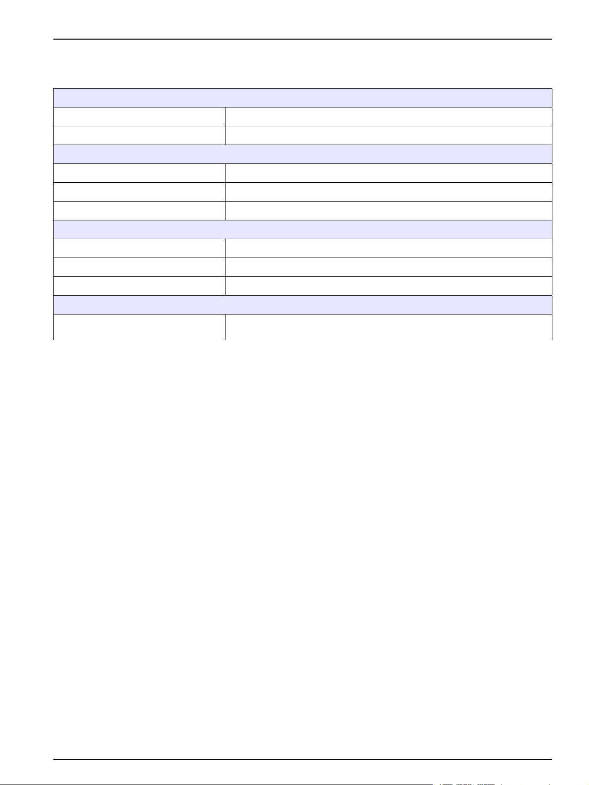
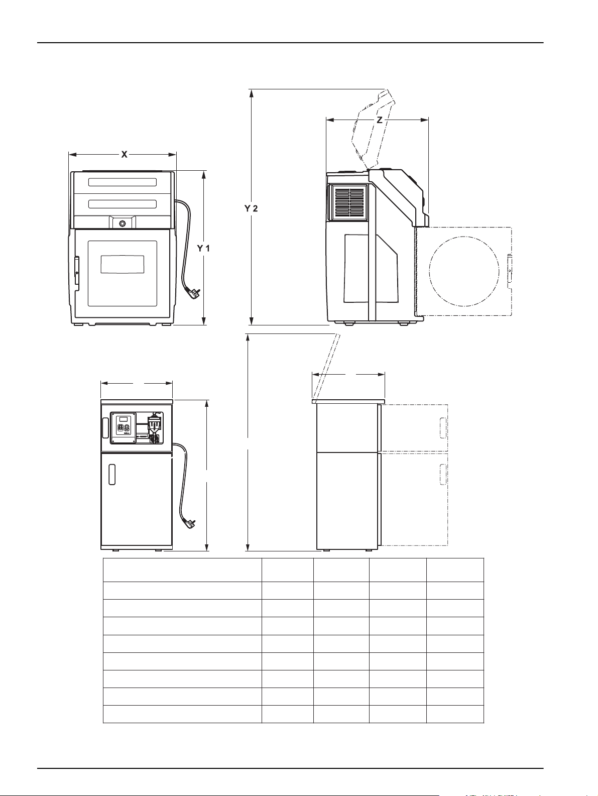
Dimensions (W × H × D) See Figure 1
Certification
Certification
CE, MCERTS (not 3010)
Sampling in accordance with ISO 5667-2/3-10
5
Page 6
Specifications
5
jkl6mno4ghi
8
tuv wxyz97pqrs
2
abc3def
1
0
Y1
X
Z
Y2
BÜHLER 3010
BÜHLER 4010
BÜHLER 6010
BÜHLER 4210
BÜHLER 4410 (2–12 Flaschen)
BÜHLER 4410 (24 Flaschen)
BÜHLER 4210 (23 Flaschen)
BÜHLER 4110
mm [in.]
Y1
1100 [43.3]
1325 [52.2]
1690 [66.5]
1325 [52.2]
1325 [52.2]
1415 [55.7]
1415 [55.7]
1475 [58.1]
mm [in.]
X
760 [30]
605 [23.8]
1200 [47.2]
605 [23.8]
605 [23.8]
715 [28.1]
715 [28.1]
605 [23.8]
mm [in.]
Y2
1640 [64.6]
1895 [74.6]
2260 [89]
1895 [74.6]
1895 [74.6]
2120 [83.5]
2120 [83.5]
2030 [79.9]
mm [in.]
Z
725 [28.5]
645 [25.4]
645 [25.4]
645 [25.4]
810 [31.9]
810 [31.9]
645 [25.4]
645 [25.4]
(23 bottles)
(2–12 bottles)
(24 bottles)
1.1 Dimensions
6
Figure 1 Dimensions
Page 7
Section 2 General information
2.1 Safety information
Please read this entire manual before the equipment is unpacked, set up or operated. Pay
attention to all danger and caution statements. Personal injury or damage to the
equipment could occur if they are not observed.
To ensure that the protection provided by this equipment is not impaired, do not use or
install this equipment in any manner other than that specified in this manual.
2.1.1 Hazard information in this manual
DANGER
Indicates a potentially or imminently hazardous situation which, if not avoided, will
result in death or serious injury.
WARNING
Indicates a potentially or imminently hazardous situation that, if not avoided, could
result in death or serious injury.
CAUTION
Indicates a potentially or imminently hazardous situation that could result in minor
or moderate injury.
Important note: Information that requires special emphasis.
Note: Information that supplements points in the main text.
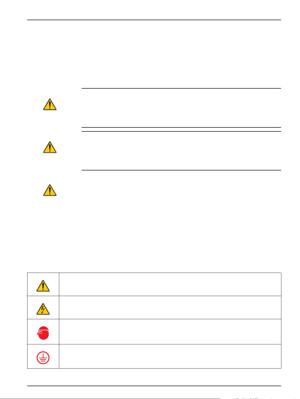
2.1.2 Warning labels
Read all labels and notices attached to the equipment. Personal injury or damage to the
equipment could occur if they are not observed. Any symbol on the equipment will appear
along with a caution statement in the manual.
This symbol, if noted on the instrument, references the user manual for operation and/or safety information.
This symbol, when noted on a product enclosure or barrier, indicates that a risk of electrical shock and/or
electrocution exists.
This symbol may appear on the product and indicates the need for protective eye wear.
This symbol may appear on the product and identifies the connection point for the protective ground.
7
Page 8
General information
When this symbol appears on the product, it identifies the location of a fuse or a current limiter.
Electrical equipment marked with this symbol may not be disposed of in European domestic or public disposal
systems after 12 August 2005. In conformity with European local and national regulations (EU Directive
2002/96/EC), European electrical equipment users must now return old or end-of life equipment to the
manufacturer for disposal at no charge to the user.
Note: For return for recycling, please contact the equipment manufacturer or supplier for instructions on how
to return end-of-life equipment, manufacturer-supplied electrical accessories, and all auxiliary items for proper
disposal.
2.2 General information
2.2.1 Areas of application
The equipment is used for sampling aqueous liquids with a temperature between 0°C
and 40°C [32 to 104 °F].
2.2.2 Functional description
The equipment provides temporary storage for liquids of a specified volume so that they
can be analyzed.
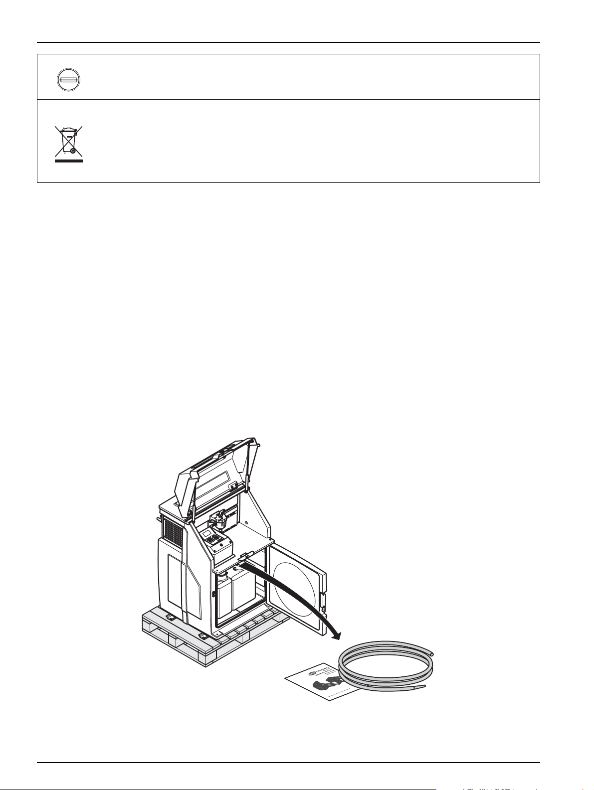
2.3 Scope of delivery
The equipment is supplied with a tube and a short manual.
If you require further information, you can order the operating instructions (refer to
Section 6 Spare parts and accessories, page 55) from the manufacturer or you can
download it from the Internet.
Figure 2 Scope of delivery (3010)
8
Page 9
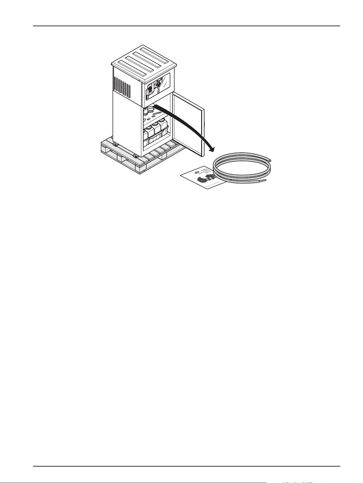
General information
Figure 3 Scope of delivery (4010–6010)
9
Page 10

General information
10
Page 11

Section 3 Installation
DANGER
Only qualified experts should conduct the tasks described in this section.
DANGER
Select an appropriate installation location for the instrument.
Plan out the mechanical mount·before positioning poles or drilling holes. Make
sure the mount has a sufficient bearing capacity. The dowels must be selected and
authorized according to the condition of the wall.
The manufacturer shall accept no liability if the instrument is installed incorrectly.
Plan how to lay cables and tubes and their path in advance. Lay the tubes, data
cables and power cables without any bends and so they do not pose a tripping
risk.
Do not connect the electrical supply to the mains if the equipment has not been
wired and fused correctly.
Sufficiently protect the electrical power supply against short circuits.
For the external power supply, always connect a residual-current circuit
breaker·(trip current max.: 30 mA) between the mains and the system.
If the equipment is to be installed outdoors, switch the overload prot ection
between mains and system.
Products intended by the manufacturer for outdoor use offer a higher level of
protection against the penetration of liquids and dust. If these products are
connected to a mains outlet with a cable and plug·rather than a permanently
connected cable, the plug and outlet are much more susceptible to liquid and dust
penetration. The operator must sufficiently protect the plug and outlet against
liquid and dust penetration in accordance with local safety regulations. If the
instrument is to be used outdoors, it must be connected to a suitable outlet with a
protection type of at least IP44 (splash protectio n).
11
Page 12
Installation
17 mm
3.1 Mechanical installation
DANGER
Select an appropriate installation location for the instrument.
Plan out the mechanical mount·before positioning poles or drilling holes. Make
sure the mount has a sufficient bearing capacity. The dowels must be selected and
authorized according to the condition of the wall.
The manufacturer shall accept no liability if the instrument is installed incorrectly.
Plan how to lay cables and tubes and their path in advance. Lay the tubes, data
cables and power cables without any bends and so they do not pose a tripping
risk.
Note: For information on installation with optional accessories, refer to the relevant installation
instructions.
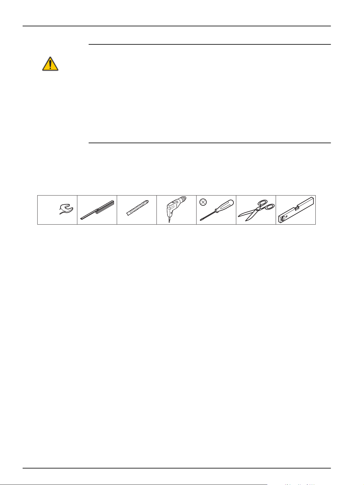
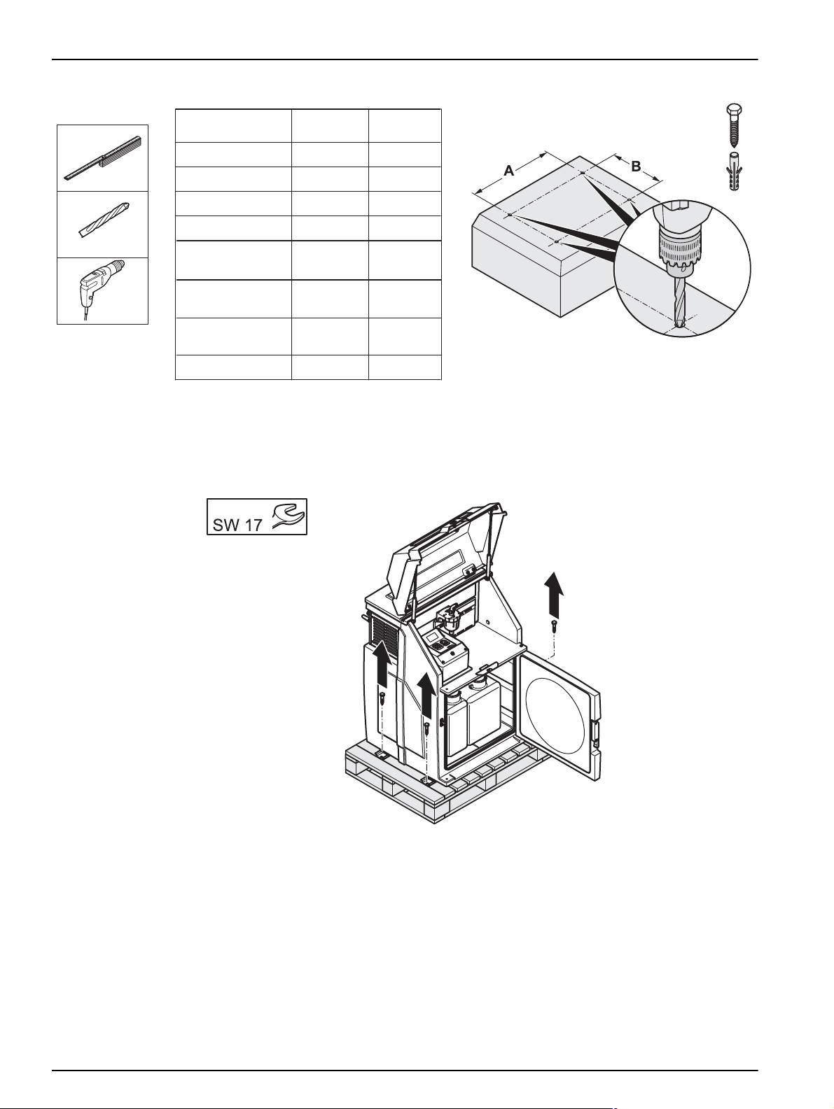
3.1.1 Required tools
Figure 4 Required tools
12
Page 13
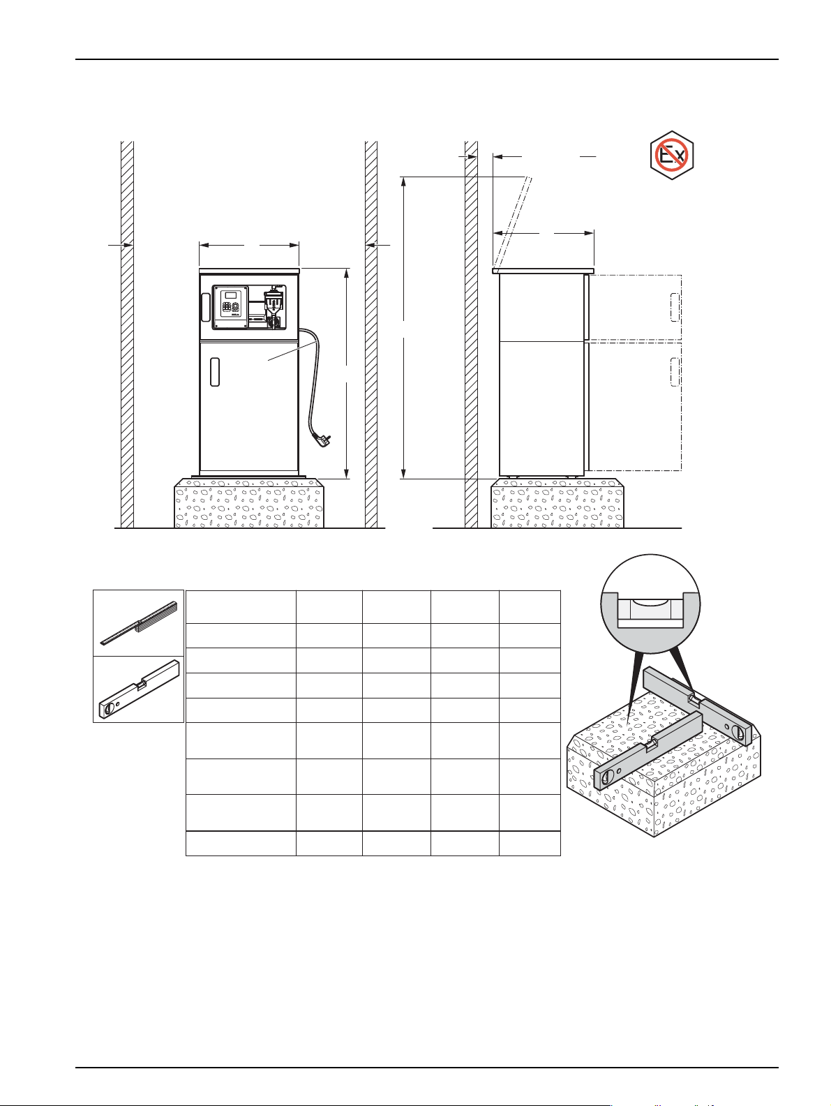
3.1.2 Select installation location
≥50mm
[2 in]≥
Z
Y2
5
jkl6mno4ghi
8
tuv wxyz97pqrs
2
abc3def
1
0
2500 mm
[100 in]
≥ 500 mm
[20 in]≥
≥ 500 mm
[20 in]≥
Y1
X
BÜHLER 4010
BÜHLER 3010
BÜHLER 4210
BÜHLER 4410
(2–12 Flaschen)
BÜHLER 4210
(23 Flaschen)
BÜHLER 4410
(24 Flaschen)
BÜHLER 4110
BÜHLER 6010
X
mm [in.]
605 [23.8]
760 [30]
605 [23.8]
715 [28.1]
605 [23.8]
715 [28.1]
605 [23.8]
1200 [47.2]
Y1
mm [in.]
1325 [52.2]
1100 [43.3]
1325 [52.2]
1415 [55.7]
1325 [52.2]
1415 [55.7]
1475 [58.1]
1690 [66.5]
mm [in.]
Y2
1895 [74.6]
1640 [64.6]
1895 [74.6]
2120 [83.5]
1895 [74.6]
2120 [83.5]
2030 [79.9]
2260 [89]
mm [in.]
Z
645 [25.4]
725 [28.5]
645 [25.4]
810 [31.9]
645 [25.4]
810 [31.9]
645 [25.4]
645 [25.4]
Ex
(2–12 bottles)
(24 bottles)
(23 bottles)
Installation
Figure 5 Select installation location
13
Page 14
Installation
³ Ø12×60mm
mm [in.]
A
730 [28.7]
660 [26]
660 [26]
660 [26]
660 [26]
770 [30.3]
770 [30.3]
1260 [49.6]
B
mm [in.]
384 [15.1]
383 [15.1]
383 [15.1]
383 [15.1]
383 [15.1]
500 [19.7]
500 [19.7]
383 [15.1]
BÜHLER 3010
BÜHLER 4010
BÜHLER 4110
BÜHLER 4210
BÜHLER 4410
(2–12 Flaschen)
BÜHLER 4410
(23 Flaschen)
BÜHLER 4410
(24 Flaschen)
BÜHLER 6010
(2–12 bottles)
(24 bottles)
(23 bottles)
3.1.3 Unpacking
Figure 6 Prepare the installation location
14
Figure 7 Move the equipment from the transport pallet (3010)
Page 15
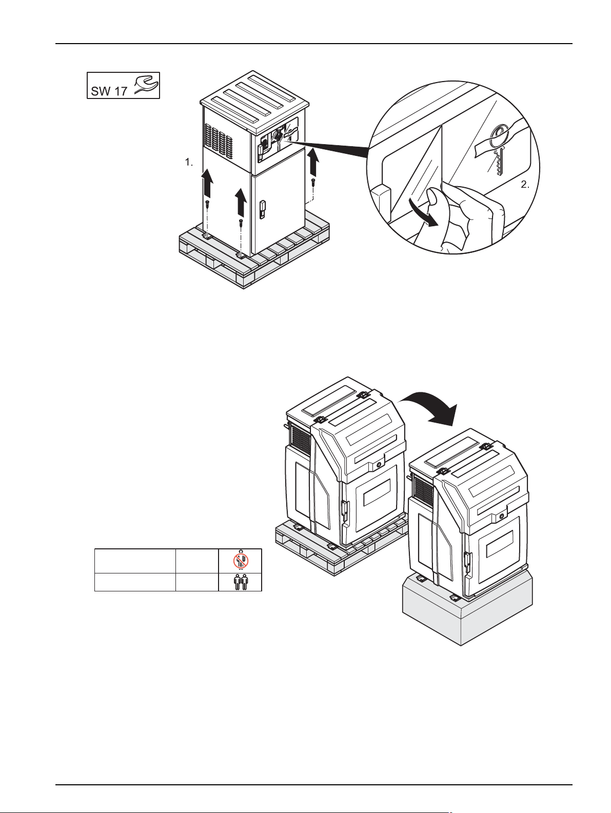
Figure 8 Move the equipment from the transport pallet (4010–6010)
BÜHLER 3010
kg
75
Installation
3.1.4 Set up
Figure 9 Set up the equipment (3010)
15
Page 16
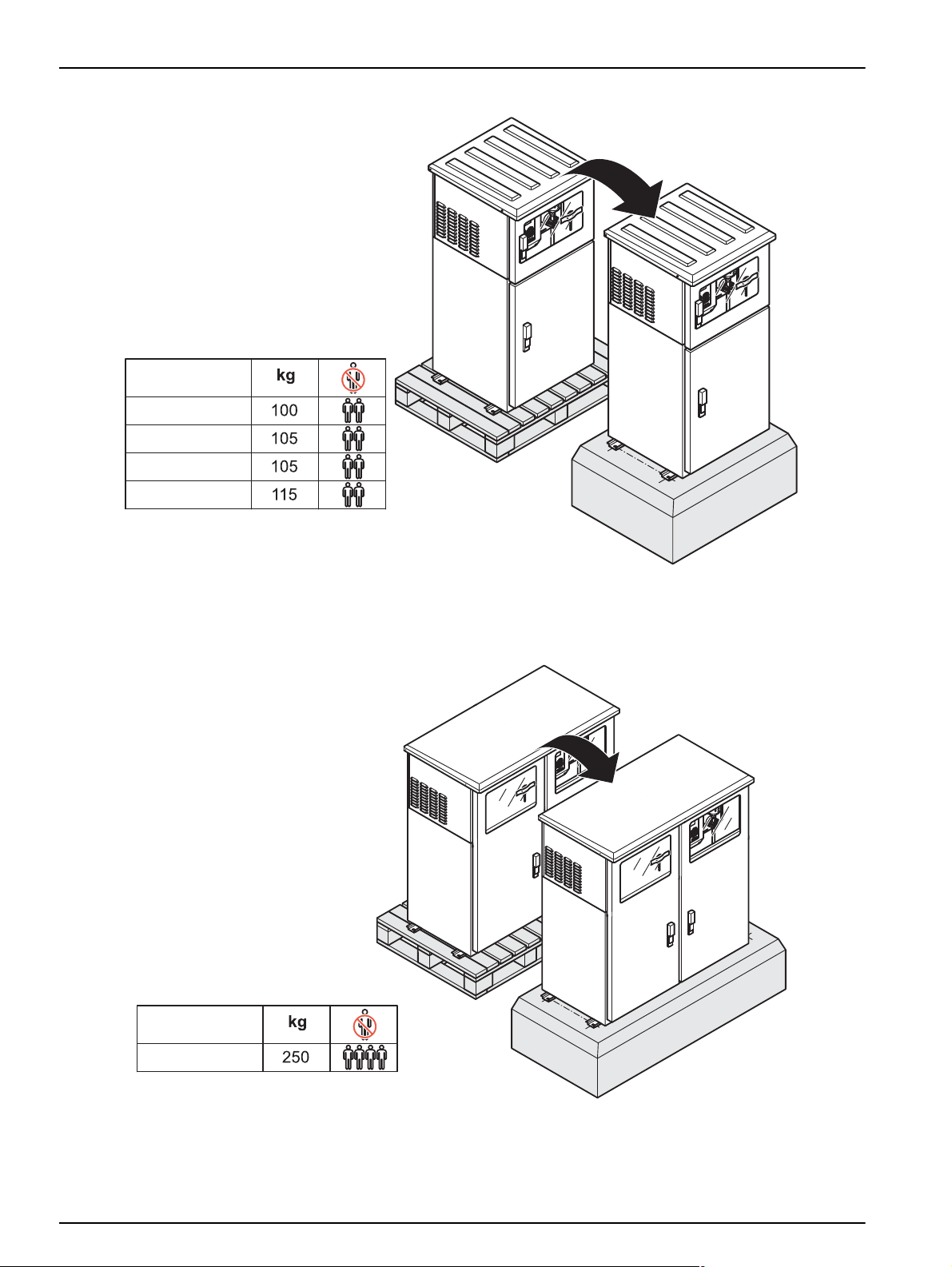
Installation
BÜHLER 4010
BÜHLER 4210
BÜHLER 4410
BÜHLER 4110
BÜHLER 6010
Figure 10 Set up the equipment (4xx0)
16
Figure 11 Set up the equipment (6010)
Page 17

Installation
³ Ø12×60mm
>80Nm
³ 17 mm
Figure 12 Align and secure the equipment
3.2 Electrical connections
DANGER
Only qualified experts should conduct the tasks described in this section.
DANGER
Do not connect the electrical supply to the mains if the equipment has not been
wired and fused correctly.
Sufficiently protect the electrical power supply against short circuits.
For the external power supply, always connect a residual-current circuit
breaker·(trip current max.: 30 mA) between the mains and the system.
If the equipment is to be installed outdoors, switch the overload prot ection
between mains and system.
If the mains plug·of the power supply cable·is removed, a suitable double-pole
one-way switch must be installed immediately next to the display unit·with clear
labeling for the power supply.
Products intended by the manufacturer for outdoor use offer a higher level of
protection against the penetration of liquids and dust. If these products are
connected to a mains socket with a cable and plug·rather than a permanently
17
Page 18
Installation
connected cable, the plug and socket are much more susceptible to liquid and
dust penetration. The operator must sufficiently protect the plug and outlet against
liquid and dust penetration in accordance with local safety regulations. If the
instrument is to be used outdoors, it must be connected to a suitable outlet with a
protection type of at least IP44 (splash protection).
3.2.1 Electrical installation
3.2.1.1 Prepare the electrical installation (3010)
Figure 13 Loosen the screws and remove the cover (3010)
Figure 14 Feed cable through (3010)
18
Page 19
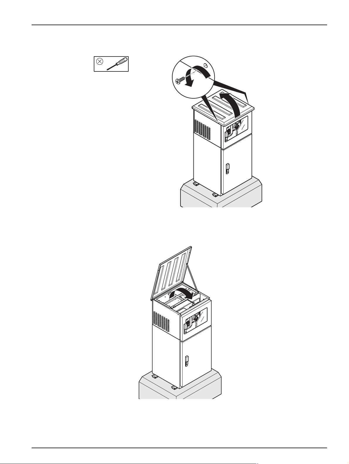
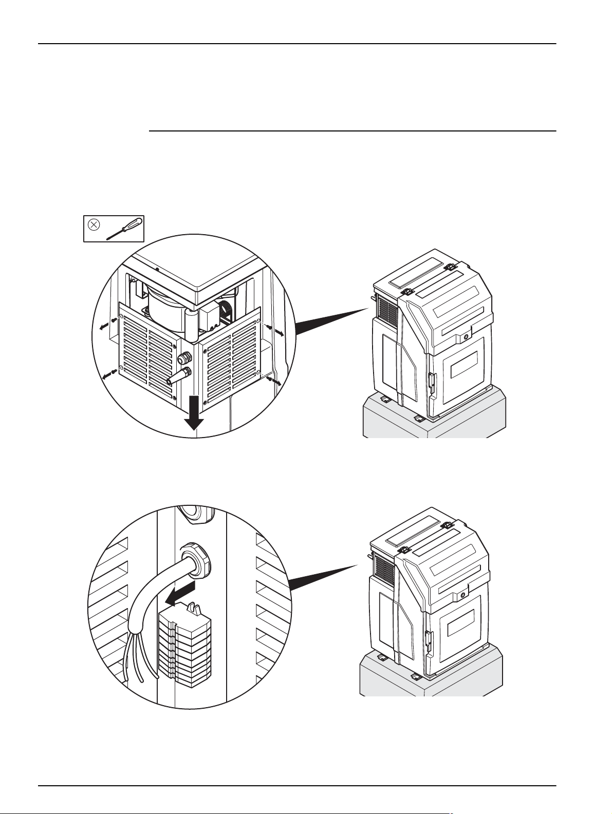
3.2.1.2 Prepare the electrical installation (4010–6010)
Installation
Figure 15 Loosen the lid screws and open the lid (4010–6010)
Figure 16 Lift up the cover (4010–6010)
19
Page 20

Installation
23456111214
14
12
11
pH
Q
In: DC 12 V
Out: AC 250V/2×8A
Kontaktbelegung: Relais
pH
Q
Pin assignment: relay
3.2.1.3 Wiring diagram (3010)
Figure 17 Wiring diagram (3010)
3.2.1.4 Wiring diagram (4010–6010)
20
Figure 18 Wiring diagram (4010–6010)
Page 21

3.2.1.5 Complete the electrical installation (3010)
Installation
Figure 19 Attach cover
3.2.1.6 Complete the electrical installation (4010–6010)
Figure 20 Shut the cover
If suction tube is not connected immediately, close the housing lid as described in
Figure 24, page 23 and Figure 25, page 24.
21
Page 22

Installation
3.3 Commission the equipment
3.3.1 Tube connection
Figure 21 Key storage location
22
Figure 22 Feed the suction tube though housing opening
Page 23

Installation
Figure 23 Screw in the union nut
Figure 24 Close the lid
23
Page 24

Installation
–20–+40 °C
[–4–+104 °F]
0–+40 °C
[+32–+104 °F]
>50µs
³ 1000 mm
[40 in]³
£ 8000 mm
[21.3 ft]£
£ 30.000 mm
[100 ft]£
ExH2S
Figure 25 Screw down the lid tightly
Position the tubes in accordance with the following installation diagram.
24
Figure 26 Installation diagram
Page 25

3.3.2 Set the individual sample volumes
3.3.2.1 Plastic dosing vessel
Installation
Figure 27 Release the plastic dosing vessel
Figure 28 Remove the plastic dosing vessel
25
Page 26

Installation
V-Probe [mL]
= 150 mL
Figure 29 Cut the dosing tube to set the sample volume
26
Figure 30 Reinstall the plastic dosing vessel
Page 27

3.3.2.2 Glass dosing vessel
100 mL = 100 mL
100 mL = 100 mL
Installation
Figure 31 Adjust the dosing pipe to set the sample volume
3.3.2.3 Dosing vessel for flow-proportional sampling
Figure 32 Calibrate the flow-proportional dosing vessel via the service menu
27
Page 28

Installation
DP = 0 [hPa, bar]
4–20 L/Min.
+mL
–mL
DP = 0 [hPa, bar]
Notüberlauf
Emergency overflow
Figure 33 The flow-proportional dosing vessel may only be used,
3.3.2.4 Bypass dosing vessel
if there is NO counter pressure
28
Figure 34 Set the sample volume of the bypass dosing vessel
Page 29

3.3.2.5 Flush water connection and drain (4210/4410)
Schlauchtülle: ¾”
Schlauch Ø (innen) 25 mm
Hose nozzle: ¾"
Hose: Ø (internal) 25 mm
Schlauch ID 25 mm
Schlauchtülle ¾”
Hose: Ø (internal) 25 mm
Hose nozzle: ¾"
Installation
Figure 35 Flush water connection and drain (4210)
Figure 36 Flush water connection and drain (4410)
29
Page 30

Installation
DP = 0 [hPa, bar]
Schlauchtülle: ½”
Schlauch: Ø (innen) 12 mm
Schlauchtülle: Ø (innen) 40 mm
Tube nozzle: ½"
Tube:
Tube nozzle:
Ø (internal) 40 mm
Ø (internal) 12 mm
3.3.2.6 Water circuit diagram (6010)
Figure 37 Water circuit diagram (6010)
3.3.3 Preparing the sample containers (3010, 4010, 4110, 4210, 6010)
30
Figure 38 Place the empty bottles in the housing
Page 31

Figure 39 Close the door
Installation
3.3.4 Connect the equipment to the mains
Make sure that:
• The equipment has been fully prepared for commissioning
• The values on the rating label correspond with those of the mains supply
• The correct plug has been attached or the direct wire has been implemented correctly
• The equipment can be put into operation without any risks
Figure 40 Rating label
31
Page 32

Installation
3m
[10 ft]
3m
[10 ft]
Figure 41 Possible connection configurations
32
Page 33

Section 4 Operation
4.1 Control unit operation
All the equipment functions are software-controlled.
4.1.1 Password
Password to program sampler and to change settings is:
4.1.2 Programming
The menu structure resembles the directory structure of a computer hard drive and is
divided into main menus and sub menus.
4.1.2.1 Keyboard layout/function
The equipment is programmed by the operator.
6299
Figure 42 Control panel
The key functions are configured as follows to enable highly intuitive operation:
Table 1 Key functions
Display help text
(in the case of selection fields,
the cursor must be placed on the left-hand side)
Move from one menu item to the next menu selection Arrow keys
Select the menu required Enter key
Move within a menu Arrow keys
Arrow key
33
Page 34

Operation
Table 1 Key functions (Continued)
Select from within a menu Arrow keys
Confirm the selection
(automatically marked with a )
Enter/change values Arrow keys
Confirm the entered values Enter key
Return to the next superordinate menu level Back key
Enter values
RESET (restore factory settings)
Press and hold Back for at least 10 seconds
Enter key
Numeric
keypad
Back key
Example: A setting needs to be changed.
1. Press Enter.
The cursor then flashes.
2. Use the arrow keys to move the cursor until it is in the required position.
3. Press Enter.
The selection is now confirmed and the program can be started.
34
Page 35

Figure 43 Start the program
Depending on the program range,
Operation
• an activity is started or
• the next menu item is automatically selected.
Note: The general rule:
If you press Back,
– the activity is cancelled or
– the navigation takes one step back in the menu.
4.2 Normal operation
The described normal operation applies to several models
(e.g.) 3010, 4010, 4011, 4110, 4210, 4411).
The 3010, 4011 and 4411 models are displayed as examples in the images.
35
Page 36

Operation
4.2.1 Replace the sample bottles (3010, 4010, 4110, 4211)
Figure 44 Open the door
36
Figure 45 Remove the full bottles
Page 37

Operation
Figure 46 Replace with empty bottles
Figure 47 Close the door
37
Page 38

Operation
4.2.2 Sampling (4411 with 12 or 24 bottles)
Figure 48 Press PAUSE to suspend the current program (4411 with 12 or 24 bottles)
Figure 49 Select to remove the sample (4411 with 12 or 24 bottles)
38
Page 39

Figure 50 Select bottle number (4411 with 12 or 24 bottles)
Operation
Figure 51 Swivel out the sample faucet (4411 with 12 or 24 bottles)
39
Page 40

Operation
Figure 52 Press the lever to open the sample faucet
(4411 with 12 or 24 bottles)
40
Figure 53 Swivel the lever back to close the sample faucet (4411 with 12 or 24 bottles)
Page 41

Operation
Figure 54 Swivel in the sample faucet (4411 with 12 or 24 bottles)
Figure 55 Select to continue the program (4411 with 12 or 24 bottles)
41
Page 42

Operation
4.2.3 Sampling (4411 with 2 or 4 bottles)
Figure 56 Select pause (4411 with 2 or 4 bottles)
Figure 57 Release the bottle holder (4411 with 2 or 4 bottles)
42
Page 43

Operation
Figure 58 Pull out the bottle holder and take sample (4411 with 2 or 4 bottles)
Figure 59 Select to remove sample (4411 with 2 or 4 bottles)
43
Page 44

Operation
Figure 60 Select the bottle number (4411 with 2 or 4 bottles)
44
Figure 61 Push the bottle holder back in and secure (4411 with 2 or 4 bottles)
Page 45

Figure 62 Select to continue program (4411 with 2 or 4 bottles)
Operation
45
Page 46

Operation
46
Page 47

Section 5 Maintenance and cleaning
DANGER
Only qualified experts should conduct the tasks described in this section.
WARNING
Please observe the following points for the use of chemicals and/or waste water:
Wear protective clothing:
– Laboratory coat
– Protective eyewear
– Rubber gloves
5.1 Maintenance tasks
The equipment is maintenance-free, therefore the operator does not need to carry out any
maintenance work.
5.2 Cleaning
5.2.1 Clean the housing and distribution unit
WARNING!
Manual rotation of the distribution unit can damage the dr ive.
Never rotate the distribution unit manually.
Clean the interior and exterior of the housing with a damp, lint-free cloth. Add commercial
household cleaner to the cleaning water as required.
47
Page 48

Maintenance and cleaning
Figure 63 NEVER rotate the distribution unit manually
48
Figure 64 Clean the distribution unit
Page 49

5.2.2 Clean the dosing vessel
Maintenance and cleaning
Figure 65 Release the dosing vessel
Figure 66 Remove the dosing vessel
49
Page 50

Maintenance and cleaning
Figure 67 Clean the dosing vessel
Figure 68 Insert the dosing vessel
50
Page 51

5.3 Troubleshooting
If the equipment does not function as required, check the fuse and replace if necessary.
5.3.1 Open the housing to change the fuse (3010)
Maintenance and cleaning
Figure 69 Open the lid and detach the cover (3010)
Figure 70 Remove the safety cover (3010)
51
Page 52

Maintenance and cleaning
5×20mm
8 A (träge)
(inactive)
5.3.2 Open the housing to change the fuse (4010–6010)
Open the housing lid as described in Figure 15, page 19 and Figure 16, page 19.
5.3.3 Change the fuse
Figure 71 Fuse support
If the error is not rectified, please contact the customer service of the manufacturer (refer
to Contact information, page 61).
52
Page 53

5.3.4 Reassemble the housing (3010)
Maintenance and cleaning
Figure 72 Install the safety cover (3010)
Figure 73 Close the housing (3010)
53
Page 54

Maintenance and cleaning
5.3.5 Reassemble the housing (4010–6010)
Close the housing lid as described in Figure 20, page 21, Figure 24, page 23 and
Figure 25, page 24.
5.4 Instrument decommissioning and storage
1. Remove all liquids and, if necessary, solid matter from the infeed and outfeed lines
and sample containers and clean as required.
2. Close all active programs.
3. Switch the equipment off.
54
Page 55

BM80070
BM69452
BM80044
350 mL
BM69301
12×2
BM69302
4×1,5
BM900715
Kunststoff - Dosiereinheit
Plastic dosing vessel
Section 6 Spare parts and accessories
6.1 Spare parts
Description Cat. no.
Short Manual (xx = language number) Doc013.xx.90205
Full User Manual (xx = language number) Doc023.xx.90144
Figure 74 Plastic dosing vessel
55
Page 56

BM900053
BM69401
BM69402
BM30004
350 mL
BM69301
12×2
BM69302
4×1,5
Glas - Dosiereinheit (350 mL)
BM900674
Glass dosing vessel (350 ml)
Spare parts and accessories
Figure 75 Glass dosing vessel (350 ml)
56
Page 57

BM30005
500 mL
BM69301
12×2
BM69302
4×1,5
BM69402
BM69401
BM900053
Glas - Dosiereinheit (500 mL)
BM900243
Glass dosing vessel (500 ml)
Spare parts and accessories
Figure 76 Glass dosing vessel (500 ml)
57
Page 58

Spare parts and accessories
Bypass - Dosiereinheit (Glas)
BM69402
BM30027
250 mL
BM69301
12×2
BM69317
20×2
BM900239
Bypass dosing vessel (glass)
Figure 77 Glass dosing vessel (flow)
58
Page 59

Section 7 Warranty and liability
The manufacturer warrants that the product supplied is free of material and manufacturing
defects and undertakes the obligation to repair or replace any defective parts at zero cost.
The warranty period for instruments is 24 months. If a service contract is taken out within
6 months of purchase, the warranty period is extended to 60 months.
With the exclusion of further claims, the supplier is liable for defects including the lack of
assured properties as follows: All those parts that, within the warranty period calculated
from the day of the transfer of risk, can be demonstrated to have become unusable or that
can only be used with significant limitations due to a situation present prior to the transfer
of risk, in particular due to incorrect design, poor materials or inadequate finish will be
improved or replaced, at the supplier's discretion. The identification of such defects must
be reported to the supplier in writing without delay, but no later than 7 days after the
identification of the fault. If the customer fails to notify the supplier, the product is
considered approved despite the defect. Further liability for any direct or indirect damages
is not accepted.
If equipment-specific maintenance and servicing work defined by the supplier is to be
performed within the warranty period by the customer (maintenance) or by the supplier
(servicing) and these requirements are not carried out, claims for damages are rendered
void due to the failure to comply with the requirements.
Any further claims, in particular claims for consequential damages, cannot be made.
Consumables and damage caused by improper handling, unsafe assembly or by incorrect
use are excluded from this provision.
Process instruments of the manufacturer are of proven reliability in many applications and
are therefore often used in automatic control loops to provide the most economical
operation possible for the related process.
To avoid or limit consequential damage, it is therefore recommended to design the control
loop such that a malfunction in an instrument results in an automatic change over to the
backup control system, which is the most secure operating condition for the environment
and for the process.
59
Page 60

Warranty and liability
60
Page 61

Section 8 Contact information
HACH Company
World Headquarters
P.O. Box 389
Loveland, Colorado
80539-0389 U.S.A.
Tel (800) 227-HACH
(800) -227-4224
(U.S.A. only)
Fax (970) 669-2932
orders@hach.com
www.hach.com
HACH LANGE GMBH
Willstätterstraße 11
D-40549 Düsseldorf
Tel. +49 (0)2 11 52 88-320
Fax +49 (0)2 11 52 88-210
info@hach-lange.de
www.hach-lange.de
HACH LANGE GMBH
Rorschacherstrasse 30a
CH-9424 Rheineck
Tel. +41 (0)848 55 66 99
Fax +41 (0)71 886 91 66
info@hach-lange.ch
www.hach-lange.ch
Repair Service in the
United States:
HACH Company
Ames Service
100 Dayton Avenue
Ames, Iowa 50010
Tel (800) 227-4224
(U.S.A. only)
Fax (515) 232-3835
HACH LANGE LTD
Pacific Way
Salford
GB-Manchester, M50 1DL
Tel. +44 (0)161 872 14 87
Fax +44 (0)161 848 73 24
info@hach-lange.co.uk
www.hach-lange.co.uk
HACH LANGE FRANCE
S.A.S.
8, mail Barthélémy Thimonnier
Lognes
F-77437 Marne-La-Vallée
cedex 2
Tél. +33 (0) 820 20 14 14
Fax +33 (0)1 69 67 34 99
info@hach-lange.fr
www.hach-lange.fr
Repair Service in Canada:
Hach Sales & Service
Canada Ltd.
1313 Border Street, Unit 34
Winnipeg, Manitoba
R3H 0X4
Tel (800) 665-7635
(Canada only)
Tel (204) 632-5598
Fax (204) 694-5134
canada@hach.com
HACH LANGE LTD
Unit 1, Chestnut Road
Western Industrial Estate
IRL-Dublin 12
Tel. +353(0)1 460 2522
Fax +353(0)1 450 9337
info@hach-lange.ie
www.hach-lange.ie
HACH LANGE NV/SA
Motstraat 54
B-2800 Mechelen
Tel. +32 (0)15 42 35 00
Fax +32 (0)15 41 61 20
info@hach-lange.be
www.hach-lange.be
Repair Service in
Latin America, the
Caribbean, the Far East,
Indian Subcontinent, Africa,
Europe, or the Middle East:
Hach Company World
Headquarters,
P.O. Box 389
Loveland, Colorado,
80539-0389 U.S.A.
Tel +001 (970) 669-3050
Fax +001 (970) 669-2932
intl@hach.com
HACH LANGE GMBH
Hütteldorfer Str. 299/Top 6
A-1140 Wien
Tel. +43 (0)1 912 16 92
Fax +43 (0)1 912 16 92-99
info@hach-lange.at
www.hach-lange.at
DR. LANGE NEDERLAND
B.V.
Laan van Westroijen 2a
NL-4003 AZ Tiel
Tel. +31(0)344 63 11 30
Fax +31(0)344 63 11 50
info@hach-lange.nl
www.hach-lange.nl
HACH LANGE APS
Åkandevej 21
DK-2700 Brønshøj
Tel. +45 36 77 29 11
Fax +45 36 77 49 11
info@hach-lange.dk
www.hach-lange.dk
HACH LANGE LDA
Av. do Forte nº8
Fracção M
P-2790-072 Carnaxide
Tel. +351 214 253 420
Fax +351 214 253 429
info@hach-lange.pt
www.hach-lange.pt
HACH LANGE KFT.
Vöröskereszt utca. 8-10.
H-1222 Budapest XXII. ker.
Tel. +36 1 225 7783
Fax +36 1 225 7784
info@hach-lange.hu
www.hach-lange.hu
HACH LANGE AB
Vinthundsvägen 159A
SE-128 62 Sköndal
Tel. +46 (0)8 7 98 05 00
Fax +46 (0)8 7 98 05 30
info@hach-lange.se
www.hach-lange.se
HACH LANGE SP. ZO.O.
ul. Krakowska 119
PL-50-428 Wrocław
Tel. +48 801 022 442
Fax +48 717 174 088
info@hach-lange.pl
www.hach-lange.pl
HACH LANGE S.R.L.
Str. Căminului nr. 3,
et. 1, ap. 1, Sector 2
RO-021741 Bucureşti
Tel. +40 (0) 21 205 30 03
Fax +40 (0) 21 205 30 17
info@hach-lange.ro
www.hach-lange.ro
HACH LANGE S.R.L.
Via Riccione, 14
I-20156 Milano
Tel. +39 02 39 23 14-1
Fax +39 02 39 23 14-39
info@hach-lange.it
www.hach-lange.it
HACH LANGE S.R.O.
Zastrčená 1278/8
CZ-141 00 Praha 4 - Chodov
Tel. +420 272 12 45 45
Fax +420 272 12 45 46
info@hach-lange.cz
www.hach-lange.cz
HACH LANGE
8, Kr. Sarafov str.
BG-1164 Sofia
Tel. +359 (0)2 963 44 54
Fax +359 (0)2 866 15 26
info@hach-lange.bg
www.hach-lange.bg
HACH LANGE S.L.U.
Edif. Arteaga Centrum
C/Larrauri, 1C- 2ª Pl.
E-48160 Derio/Vizcaya
Tel. +34 94 657 33 88
Fax +34 94 657 33 97
info@hach-lange.es
www.hach-lange.es
HACH LANGE S.R.O.
Roľnícka 21
SK-831 07 Bratislava –
Vaj nory
Tel. +421 (0)2 4820 9091
Fax +421 (0)2 4820 9093
info@hach-lange.sk
www.hach-lange.sk
HACH LANGE SU
ANALİZ SİSTEMLERİ
LTD. ŞTİ.
Ilkbahar mah. Galip Erdem
Cad. 616 Sok. No:9
TR-Oran-Çankaya/ANKARA
Tel. +90312 4908300 Ext. 140
Fax +90312 4919903
bilgi@hach-lange.com.tr
www.hach-lange.com.tr
61
Page 62

Contact information
HACH LANGE D.O.O.
Fajfarjeva 15
SI-1230 Domžale
Tel. +386 (0)59 051 000
Fax +386 (0)59 051 010
info@hach-lange.si
www.hach-lange.si
ΗΑCH LANGE E.Π.Ε.
Αυλίδος 27
GR-115 27 Αθήνα
Τηλ . +30 210 7777038
Fax +30 210 7777976
info@hach-lange.gr
www.hach-lange.gr
HACH LANGE D.O.O.
Ivana Severa bb
HR-42 000 Varaždin
Tel. +385 (0) 42 305 086
Fax +385 (0) 42 305 087
info@hach-lange.hr
www.hach-lange.hr
HACH LANGE MAROC
SARLAU
Villa 14 – Rue 2 Casa
Plaisance
Quartier Racine Extension
MA-Casablanca 20000
Tél. +212 (0)522 97 95 75
Fax +212 (0)522 36 89 34
info-maroc@hach-lange.com
www.hach-lange.ma
62
 Loading...