

Page 1
Operating instructions
Water sampler
BÜHLER
2000
www.hach-lange.com
DOC023.52.90153 _BÜHLER_2000_BL1029_March09.doc
Page 2
Remarks
HACH LANGE GmbH is not liable for possible faults in this documentation. Any liability for direct or
consequential damages in connection with the delivery or the use of this device is excluded as far as it
is legal.
All rights, especially the rights for duplication, distribution and/or translation, are reserved to HACH
LANGE GmbH. Any reproduction, use or duplication of this manual, also in extracts, is prohibited by
law without the previous written agreement of HACH LANGE GmbH.
Subject to changes!
Access code for programming, system settings, key lock
Password:
Your password:
6299
Copyright by HACH LANGE GmbH © 1998 – 2009
Page 3

General information
MANUAL MODE
MEMORY
Table of contents
Table of contents .................................................................................................................................3
General information.................................................................................................................................4
Safety remarks.....................................................................................................................................4
Before putting into service ...................................................................................................................4
Permissible application........................................................................................................................4
Permissible operating and ambient conditions....................................................................................4
Redelivery for repair.............................................................................................................................5
Use of hazard information....................................................................................................................6
Precautionary labels ............................................................................................................................6
Characteristic features of the BÜHLER 2000 sampler ........................................................................9
Characteristic features of the BÜHLER 1029 sampler ......................................................................11
Sampler Bühler 1029 in combination with insulating box (Isobox) ....................................................12
Installing the apparatus......................................................................................................................13
Connections Bühler 2000 ..................................................................................................................14
Connections Bühler 1029 ..................................................................................................................14
Connector assignment – RS 232.......................................................................................................15
Connector assignment – input signals ............................................................................................15
Connector assignment – battery connection ..................................................................................15
Connector assignment – message ....................................................................................................16
Troubleshooting - general..................................................................................................................16
Sampling modes................................................................................................................................17
Sampling system................................................................................................................................19
Vacuum sampling system..................................................................................................................19
Troubleshooting – vacuum system....................................................................................................21
Programming .....................................................................................................................................22
EXAMPLES FOR STANDARD PROGRAMS .......................................................................................23
MAIN MENU (root):...............................................................................................................................30
CHANGE PROGRAM .......................................................................................................................31
START PROGRAM...........................................................................................................................34
...................................................................................................................................37
SETUP ..................................................................................................................................................38
MODEM SETTINGS..........................................................................................................................39
CHANGE SYSTEM SETTINGS ........................................................................................................41
EXTENDED PROGRAM SETTINGS ................................................................................................43
..............................................................................................................................................45
SERVICE MENU...................................................................................................................................47
APPENDIX A - Special programming................................................................................................50
SPECIAL DISPLAY/MALFUNCTION MESSAGES...........................................................................54
EXTENDED MALFUNCTION MESSAGES.......................................................................................55
EXTENDED MALFUNCTION MESSAGES.......................................................................................55
MESSAGES.......................................................................................................................................55
DIGITAL INPUTS / OUTPUTS ..........................................................................................................56
Rotating distributor.............................................................................................................................57
Troubleshooting - distributor..............................................................................................................58
Maintenance ......................................................................................................................................59
Spare parts / accessories......................................................................................................................62
Circuit diagram: mains connection BÜHLER 2000/1029...................................................................64
Warranty and liability..........................................................................................................................65
Contact...............................................................................................................................................66
Page 3 Manual BÜHLER 2000/1029
Page 4

General information
General information
We are glad that you have chosen this product.
When developing this device, we combined approved technique with innovative detail solutions.
Greatest importance has also been attached to the design of an apparatus which provides easy
access for connection and maintenance works.
Safety remarks
Disconnect the mains power connections before carrying out any connection, maintenance
or repair works.
Before putting into service
- Please read these operating instructions and special remarks thoroughly before putting the
device into service.
- Familiarize yourself with the safety and operating requirements in order to safeguard
personnel and equipment.
- The apparatus has been subjected to exhaustive quality inspections before dispatch.
- Any service and maintenance works required may only be carried out by trained service
personnel.
- Observe the local safety regulations and the rules for prevention of accidents.
- Observe the rules concerning the handling of hazardous substances.
- Do only use original spare parts or spare parts authorised by the manufacturer.
- No liability or claims under guarantee will be accepted in respect of any modifications or
conversions of the apparatus, other than those carried out by us or by persons authorised by
us or for which we have given express permission (in a written form)! This also refers to any
damage due to incorrect operation and/or improper use of the equipment.
Permissible application
The permissible application of the water sampler consists in the extraction of liquid, aqueous
substances, temperature range 0°C to 40°C. The device must only be installed in areas free from
explosion hazard and must only be used for sampling of non-explosive substances. Please refer to
the technical specifications in chapter “Specifications”. Other applications are not allowed!
Permissible operating and ambient conditions
- Sample extraction of liquid aqueous substances, temperature range: 0°C to 40°C.
- The sampler is designed for operation in non-hazardous areas (no explosion risk).
- The sampler can be operated at ambient temperatures from 0°C to +45°C.
- Sampling from pressurised lines is not possible.
- The device is weather-proof and suitable for outside operation.
Page 4 Manual BÜHLER 2000/1029
Page 5

General information
Redelivery for repair
Before returning any appliances to us, please pay attention to the following to avoid unnecessary cost
and repair delays:
- Redeliveries only after agreement by the supplier
- All appliances or parts returned to us for repair must be cleaned and free of any hazardous
substances whatsoever (acids, alkaline solutions, solvents, etc.) as in Germany official
regulations regarding waste stipulate that persons in possession of hazardous waste are
responsible for its disposal and that, at the same time, employers are responsible for
protecting their employees against hazardous materials.
- Any cleaning or disposal required to be carried out by us will be charged for accordingly.
All packing materials can be disposed of as usual.
Packing materials are: cardboard, wood, PS and PE.
If the packing is returned free of cost, we will take care of its disposal.
Page 5 Manual BÜHLER 2000/1029
Page 6
General information
Safety information
Use of hazard information
Please read this entire manual before unpacking, setting up
or operating this equipment. Pay attention to all danger and
caution statements. Failure to do so could result in serious
injury to the operator or damage to the equipment.
To ensure that the protection provided by this equipment is
not impaired, do not use or install this equipment in any
manner other than that specified in this manual.
DANGER
Indicates a potentially or imminently hazardous situation
which, if not avoided, could result in death or serious injury.
CAUTION
Indicates a potentially hazardous situation that may result in
minor or moderate injury.
Important Note: Information that requires special
emphasis.
Note: Information that supplements points in the main text.
Precautionary labels
This symbol, if noted on the instrument, references the instruction manual for operation
and/or safety information.
This symbol, when noted on a product enclosure or barrier, indicates that a risk of
electrical shock and/or electrocution exists.
This symbol, if noted on the product, indicates the need for protective eye wear.
This symbol, when noted on the product, identifies the location of the connection for
Protective Earth (ground).
This symbol, when noted on the product, identifies the location of a fuse or current
limiting device.
Electrical equipment marked with this symbol may not be disposed of in European public
disposal systems after 12 August 2005. In conformity with European local and national
regulations (EU Directive 2002/96/EC), European electrical equipment users must now
return old or end-of life equipment to the Producer for disposal at no charge to the user.
Note: For all electrical products (marked or unmarked) which are supplied or produced
by Hach-Lange, please contact the local Hach-Lange sales office for instructions for
proper disposal.
Read all labels and tags attached to the instrument.
Personal injury or damage to the instrument could occur if
not observed.
Page 6 Manual BÜHLER 2000/1029
Page 7

Specifications
Device designation
Housing PE/PC(GF10)
Thermostatic control Insulated sample compartment (40 mm insulating layer)
Control Microprocessor control, foil keyboard, back-lit four-line LC-display
Data memory Non-volatile data memory: storage of sampling and malfunction data
Programming 6 user programs (can be edited freely)
Program start options Immediately, at a certain time, by an external signal
Program stop options End of sampling program after one program run, continuous operation
Pause mode Interruption of program at any time
Overfilling protection Adjustable from 1–999 samples/bottle
Interval setting 1 min. to 99 h 59 min. in steps of 1 minute
Pulse setting 1 to 255 pulses/sample
Manual sample extraction Possible at any time without interrupting the current program run
Program protection Up to 5 years after voltage loss
Interface RS 232
GSM modem / wireless
communication
Languages Multi-language, selectable
Signal inputs • 1x analogue: 4-20 mA, optional 0-20 mA,
Signal outputs / status
messages
Sampling method Vacuum system 20-350 ml
Single sample volume
accuracy
Suction height Max. 6,5 m (at 1013hPa)
Pumping speed >0,5 m/s at a suction height of up to at least 5 m (at 1013hPa); pump
Suction hose PVC, L=5 m, ID=9 mm (ID 16 mm at flow-proportional option).
Sampling modes Time-related, flow-dependent, flow-proportional (option), eventBottle variants 24 x 1 L PE (standard)
Bühler 2000
Option: freezer packs (200x10x8 mm)
Option: compressor cooling (12V/115V/230V)
like sample extractions, bottle changes, messages, external signals
Optional (in combination with PC software)
minimum voltage: 3,3 V (optocoupler)
• 5x digital:(flow, event, 3 inputs can be programmed freely
Max. 8 digital outputs, depending on device version; freely
programmable
< 2,8 %
capacity can be adjusted electronically
Max. hose length 30 m.
related, manual sample
13 L composite container
25 L composite container
4 x 5 L PE
16 x 1 L with freezer packs
Overall dimensions (Hxwxd)
787 x 510 x 468 mm
1030 x 548 x 470 mm with compressor cooling
Weight 22,4 kg 24x1 L version
34 kg 24x1 L version with compressor cooling (sampler incl. battery,
without suction hose, empty bottles)
Power supply 12 V/ 10 Ah lead gel battery (maintenance-free, sealed, leak proof)
115V or 230V mains-operation by means of battery charger in buffer
mode (float charge); power requirement max. 30 W
Number of samples Approx. 2000 samples per battery charge [determined at an ambient
temp. of 20° C, 1,5 m suction height, sampling interval of 1 min.] incl.
distributor advance
Ambient temperature 0 to + 45°C
Sample temperature 0 – 40°C
Page 7 Manual BÜHLER 2000/1029
Page 8

Specifications
Standards Device meets ISO 5667 standard
Wetted materials PVC, Silicone, PS, PE
Device designation
Thermostatic control Option: only in combination with insulating box (Isobox), freezer packs
Bottle variants Option:
Overall dimensions
Weight
BÜHLER 1029 (like BÜHLER 2000, however, with the following
modifications)
or compressor cooling (12V/115V/230V)
13 L composite container
25 L composite container
4 x 5 L PE bottle
24 x 1 L PE bottle
16 x 1 L bottle with freezer packs
(Hxwxd) sampler
442 x 452 x 222 mm
(Hxwxd) Insulating box – passive cooling
534 x 510 x 430 mm
(Hxwxd) Insulating box – active cooling
775 x 550 x 468 mm
11,6 kg sampler
11,5 kg insulating box – passive cooling (24x1 L)
24,0 kg insulating box – active cooling (24x1 L)
Page 8 Manual BÜHLER 2000/1029
Page 9
Installation
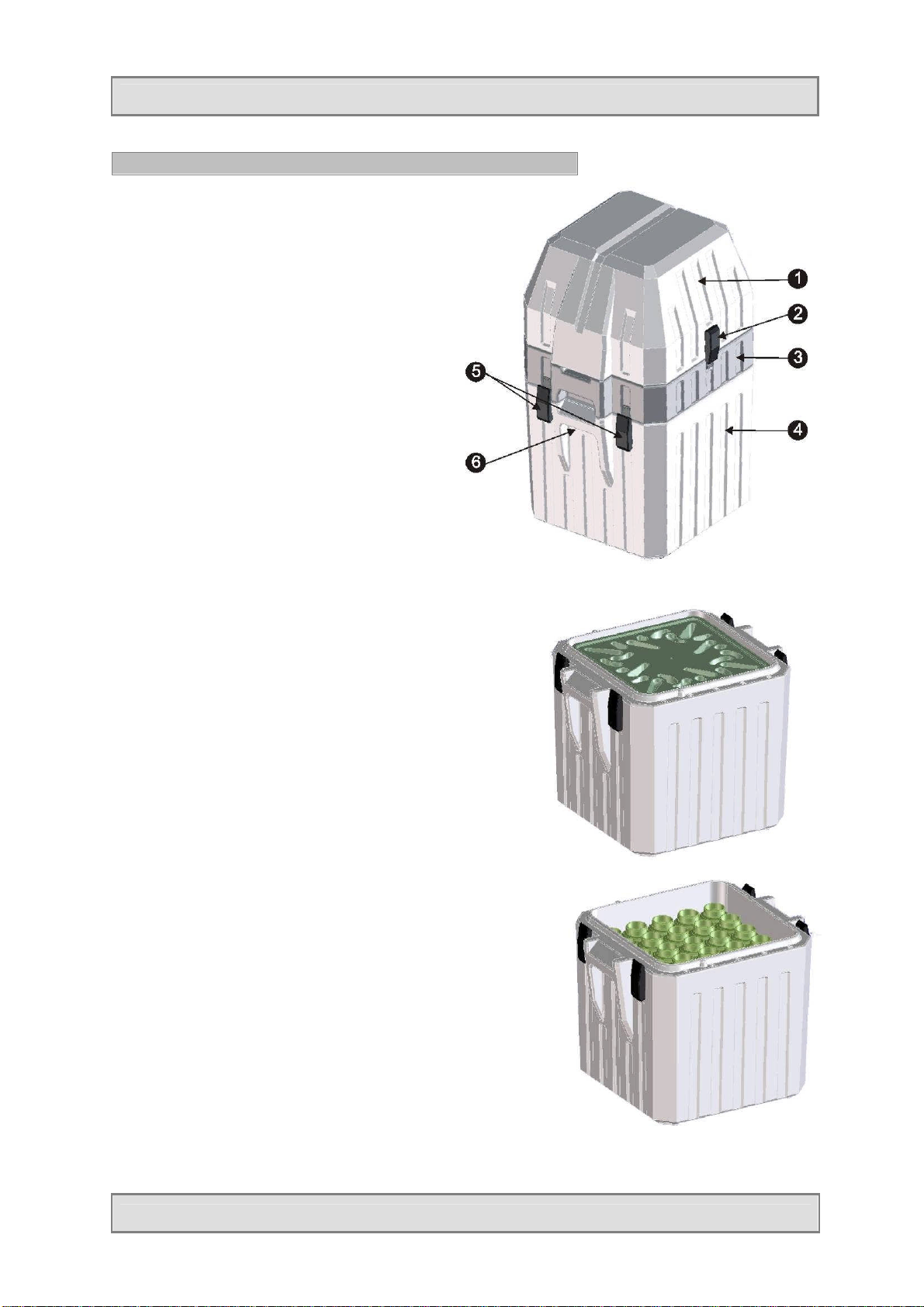
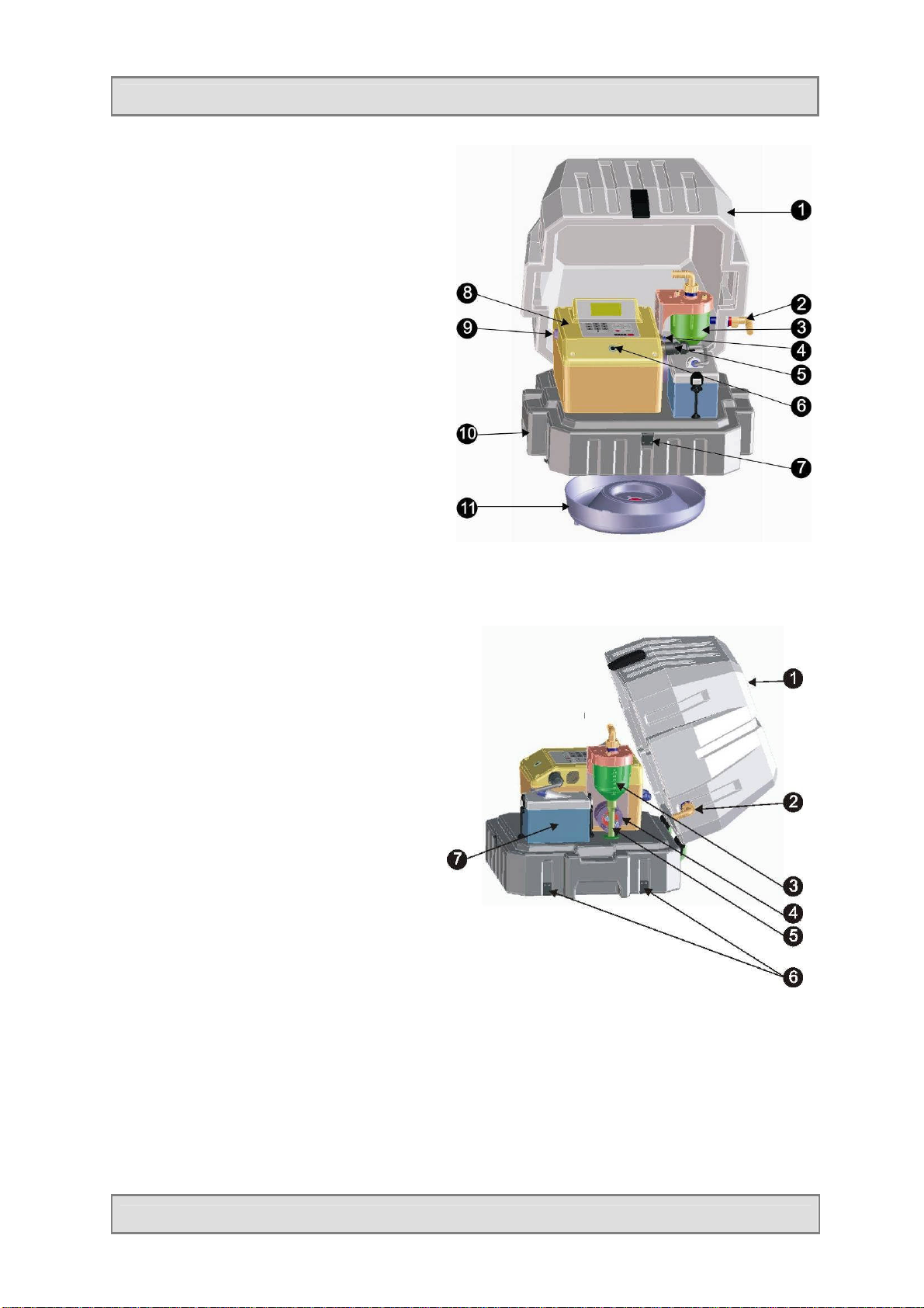
Characteristic features of the BÜHLER 2000 sampler
The device consists of the following component parts:
1. Sampler upper part
2. Snap-on lock of upper part
3. Intermediate bottom with distributor plate
4. Sampler lower part
5. Four snap-on locks at lower part (two on opposite
side)
6. Recessed grip
Lower part with inserted distributor plate
Opened lower part with bottles
Page 9 Manual BÜHLER 2000/1029
Page 10
Installation
1. Lid
2. Suction hose connector ¾“
3. Metering vessel
4. Signal connector
5. Battery connector
6. RS 232 interface
7. Lid latch
8. Control unit with keyboard and display
9. ON / OFF switch
10. Intermediate bottom of housing
11. Distributor tray
1. Lid
2. Suction hose connector ¾“
3. Metering vessel
4. Pinch valve
5. Discharge hose
6. Latches of intermediate part
7. Storage battery
Page 10 Manual BÜHLER 2000/1029
Page 11
Installation
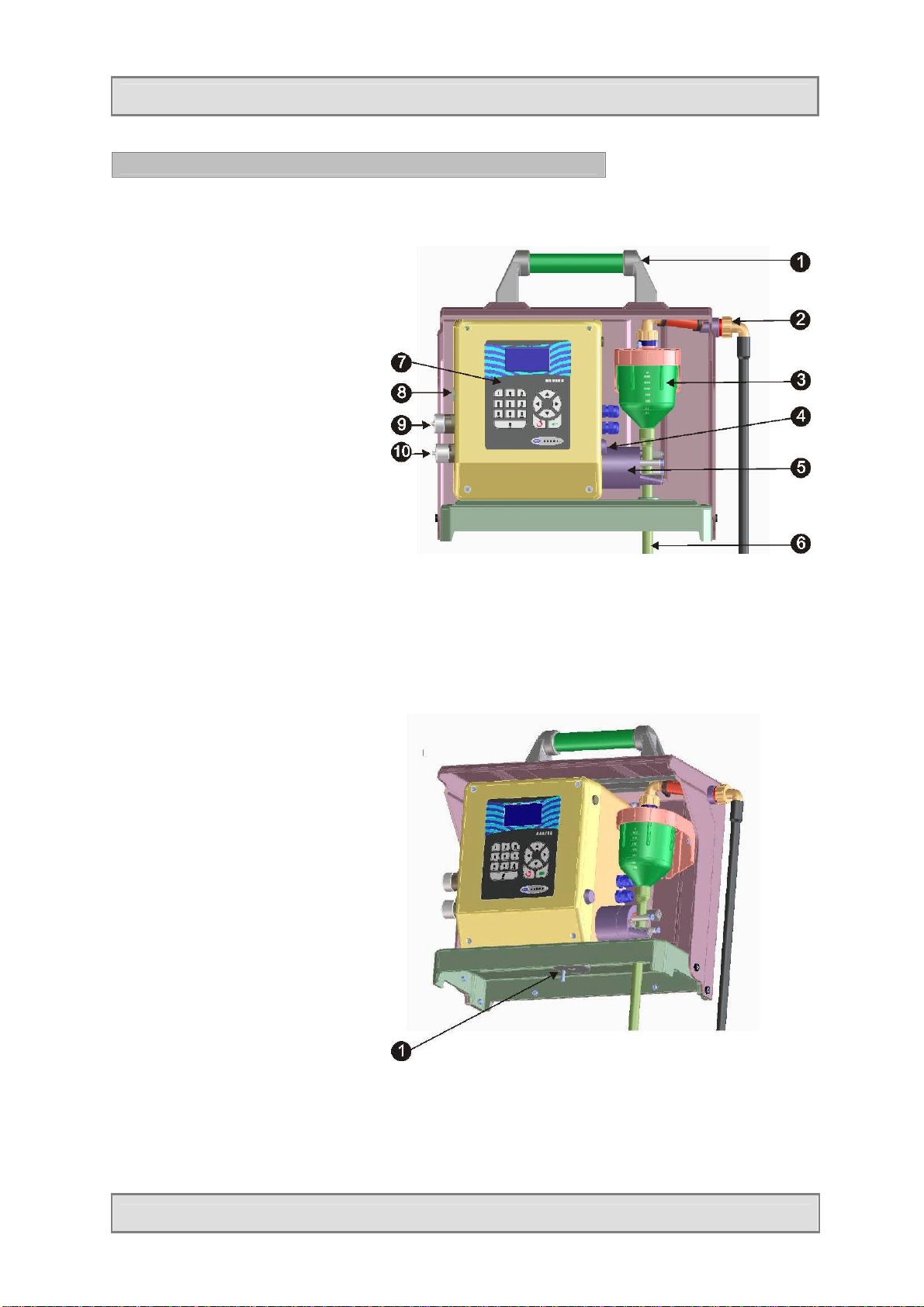
Characteristic features of the BÜHLER 1029 sampler
1. Handle
2. Suction hose connector
3. Metering vessel
4. ON / OFF switch
5. Dosing pinch valve
6. Discharge hose
7. Keyboard / display
8. Connector socket RS232
9. Connector socket of input signals
10. Connector socket of battery
charger
1. Distributor drive
Page 11 Manual BÜHLER 2000/1029
Page 12
Installation
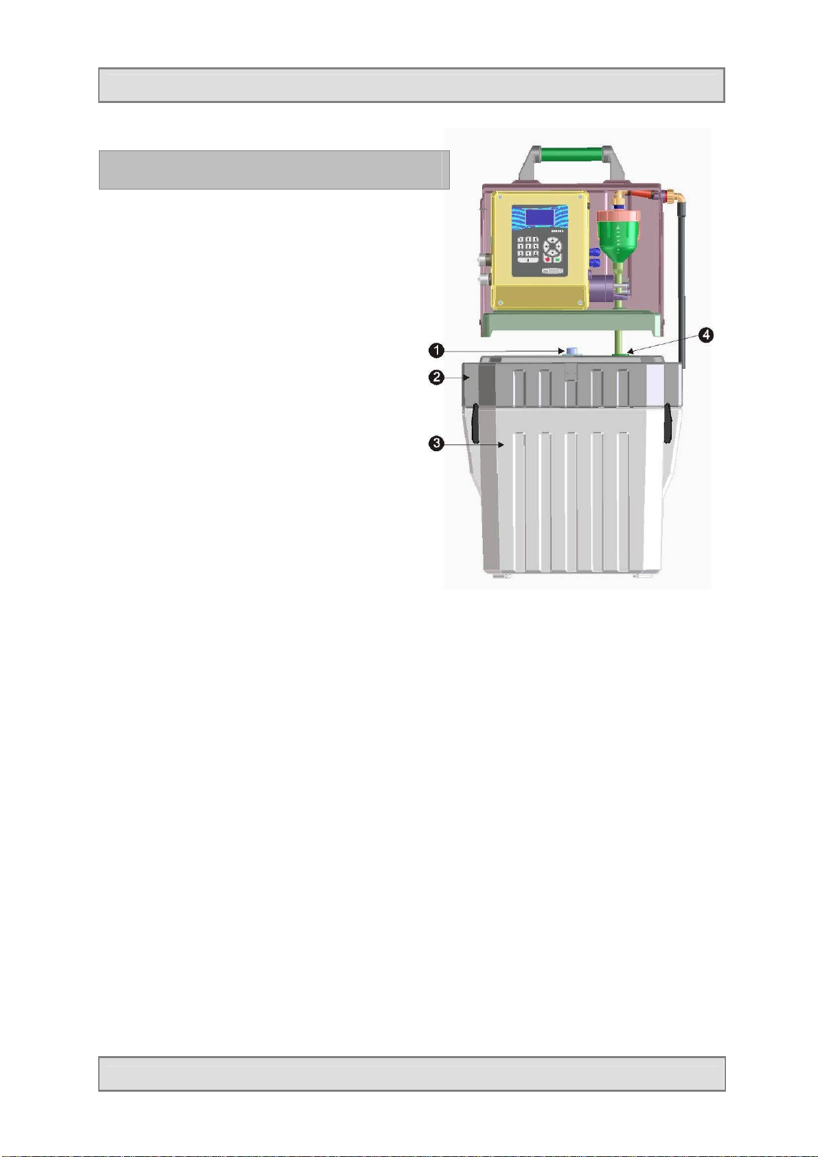
Sampler Bühler 1029 in combination with
insulating box (Isobox)
1. Distributor finger
2. Intermediate part with distributor plate
3. Lower part for bottles
4. Lead through for discharge hose of metering
vessel
Page 12 Manual BÜHLER 2000/1029
Page 13

Installation
Installing the apparatus
- We recommend to install the apparatus as close to the sampling point as possible. If installed
outside, the device should be positioned on a solid flat surface.
- The hose has to be laid with a constant fall from the sampler to the sampling point as lower
lying points can lead to deposits in the hose which may freeze in winter or result in crosscontaminations.
- To fix the suction hose, we recommend to use the extraction unit available as accessory.
- Immerse the end of the hose at the sampling point with the open end facing downstream
(direction of flow) so that coarse matter and fibres cannot be forced into the suction aperture
Mains connection / external power supply
A battery charger (option) is available to charge the battery.
Mains powered float charge option
The integral storage battery can be charged by means of the mains powered battery charger. In case
of a higher energy demand, the battery charger can be permanently connected to the mains, so that
the integral storage battery of the sampler is left permanently on charge (float charge).
Integral storage battery
A fully charged battery will, under ideal conditions, be sufficient for up to 2000 sample extractions.
Charging the storage battery
The integral battery is a maintenance-free sealed lead-acid battery.
Charge the storage battery for at least 14 -16 hours prior to the first use.
This charging time is also necessary if the storage battery is empty. To avoid a total discharge,
a protective mechanism is built-in which automatically switches off the device when the voltage
is too low.
The storage battery cannot be overcharged as the battery charger switches to compensation charge
as soon as the battery is fully charged.
For longer periods of non-use, top up the charge regularly (connect the battery to the charger).
In any case, avoid a total discharge as otherwise the storage battery will be damaged.
Switch on / off
The device is switched on and off by the ON / OFF switch.
Option: mains operation. In case of exclusive mains operation, the device is switched on by means
of the mains plug of the battery charger.
Hose connection
The inlet hose is connected at the side of the housing upper part (screw thread ¾“).
Signal connections
The signal connector (e.g. for a flow meter) is in front of the control.
Connection to a PC
The sampler is connected to a PC by means of an interface cable (art. No. BM900021) which is
connected to the RS232 connector.
Page 13 Manual BÜHLER 2000/1029
Page 14
Installation
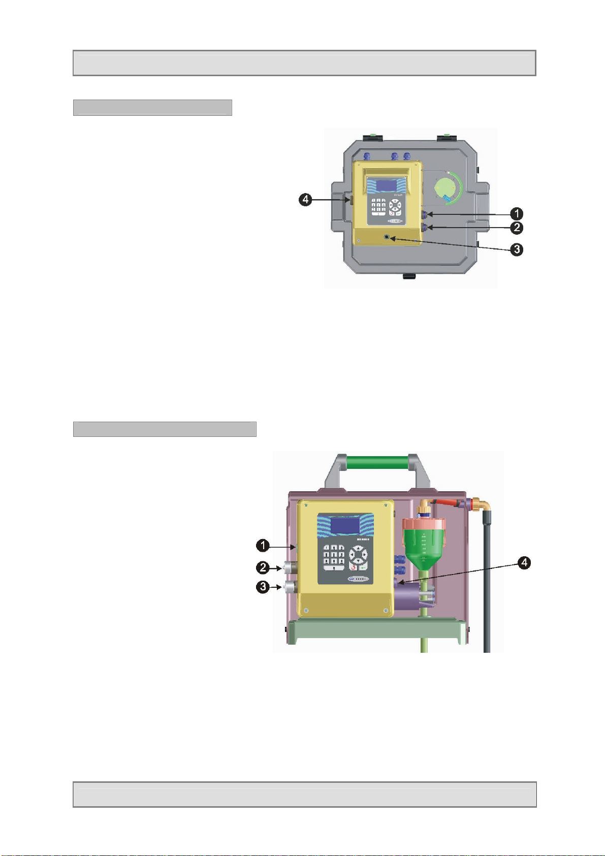
Connections Bühler 2000
1. Input signals connector
2. Battery connector 12V/10 Ah
3. RS 232 interface
4. ON / OFF switch
Connections Bühler 1029
1. RS 232 interface
2. Input signals connector
3. Battery charger connector
4. ON / OFF switch
Page 14 Manual BÜHLER 2000/1029
Page 15
Installation
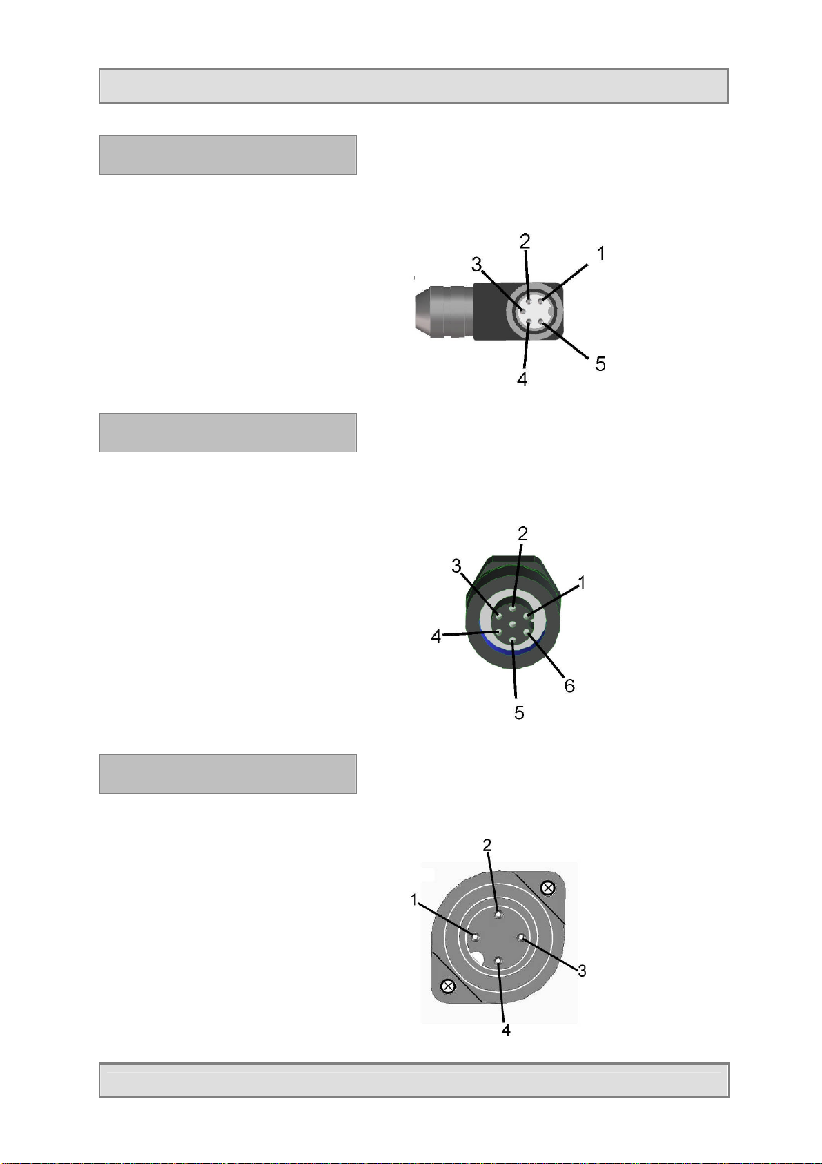
Connector assignment – RS 232
(plug)
1 = Rx
2 = Volt-free
3 = Tx
4 = Volt-free
5 = Gnd
Connector assignment – input
signals (plug)
Pin assignment:
1 = Flow analogue +
2 = Flow analogue 3 = COM
4 = Flow digital (pulse)
5 = Event
6 = Volt-free
Connector assignment – battery
connection (device)
Pin assignment:
1 = +
2 = 3 = Volt-free
4 = Volt-free
Page 15 Manual BÜHLER 2000/1029
Page 16
Installation
Connector assignment – message
• Message
Connection at relay as normally open or normally closed contact.
Troubleshooting - general
If a fault develops in your sampler, we can only provide prompt assistance if you give us the type
and serial number of the apparatus concerned. You will find these data on the type plate.
The more precise your description of the fault is, the better our fault diagnosis will be.
Symptom Possible cause Action
Check all fuses and replace
them if necessary
Charge battery for at least 14
hours
No function
Fuse defective
Battery discharged
Exhaustive discharge of battery Replace battery
Page 16 Manual BÜHLER 2000/1029
Page 17
Operation
Sampling modes
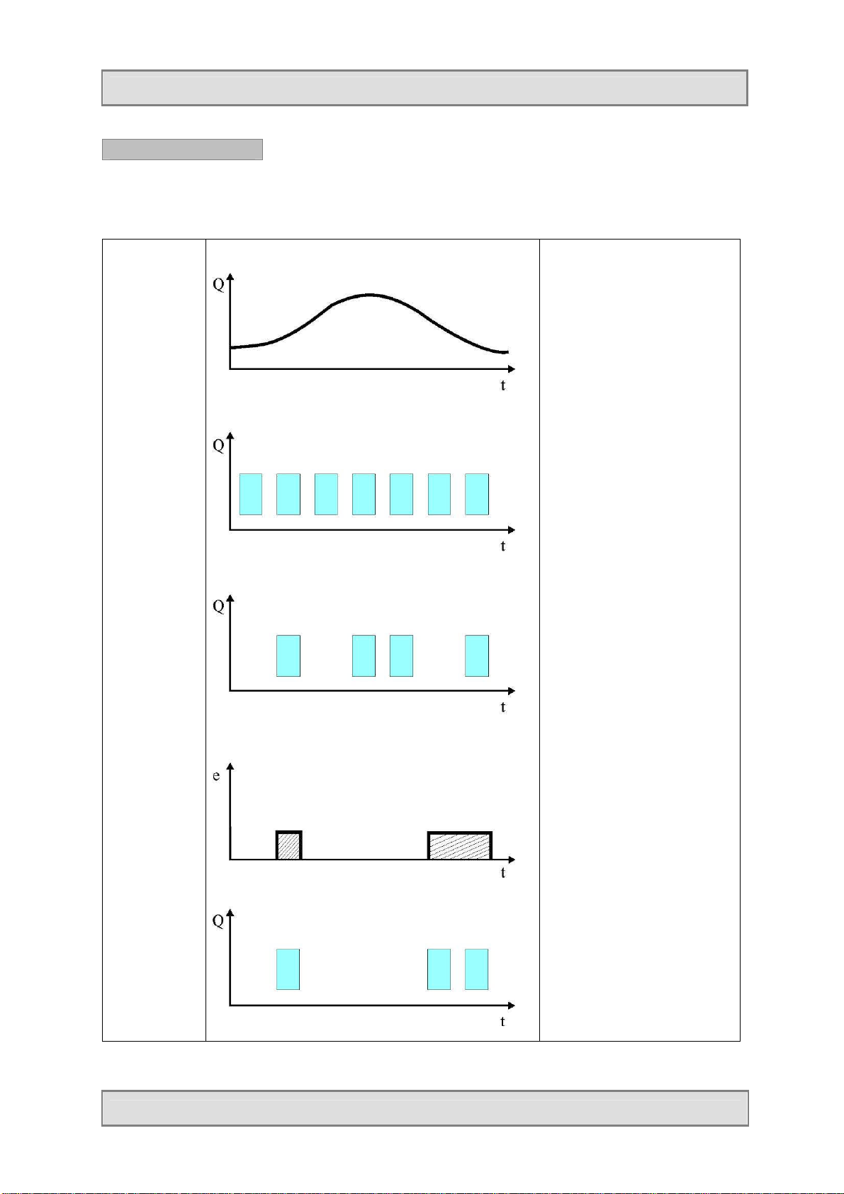
Graphical representation of sampling modes TIME-FLOW-EVENT
Flow graph
Timeproportional
Flowdependent
Event signal
Eventproportional
A sample is extracted in fixed
time intervals (e.g. every 10
minutes) with a fixed sample
volume (e.g. 50 ml).
A sample is extracted in
variable time intervals
(depending on the flow (Q))
with a fixed sample volume.
The sampler is waiting for an
event (e.g. the exceeding of
a pH limit value). A sample is
extracted in fixed time
intervals (e.g. every 10
minutes) with a fixed volume
(e.g. 50 ml) as long as an
event is present.
Page 17 Manual BÜHLER 2000/1029
Page 18

Operation
Sampling modes
The following sampling modes can be programmed:
Sampling mode Description Example
Time-proportional In this sampling mode, the single
sample extractions as well as the
bottle change are effected in fixed
time intervals.
Flow-dependent
- digital
Flow-dependent
- analogue
In this sampling mode the sample
extraction is triggered by flow
pulses. The bottle change is
effected in fixed time intervals or
after a certain number of sample
extractions.
In this sampling mode samples are
extracted according to the analogue
flow signal (0-20 mA or 4-20 mA).
The sample extraction is started
when the programmed flow is
reached. Thus the interval between
the sample extractions varies
according to the flow signal. The
bottle change is effected in fixed
time intervals or after a certain
number of sample extractions.
Values to program:
sampling interval
e.g. 00:05 hh:mm
bottle filling time
e.g. 02:00 hh:mm
Values to program:
pulse divider
e.g. 100
(that means that a sample is extracted
after each 100th pulse).
Bottle filling time
e.g. 02:00 hh:mm
or
bottle change after X sample extractions
e.g. 100
Values to program:
Flow per sample extraction
e.g. 1 m³
Bottle filling time
e.g. 02:00 hh:mm
or
bottle change after X sample extractions
e.g. 100
Event-proportional In this sampling mode the sample
extraction is depending on an
external event signal (potential-free
make contact). The sample is only
extracted as long as the signal is
present. The sampling interval as
well as the bottle change is
programmed. The bottle is changed
at each new event signal.
If an event is longer than the
programmed bottle filling time, two
or more bottles will be filled for this
event.
Page 18 Manual BÜHLER 2000/1029
Values to program:
Sampling interval
e.g. 00:05 hh:mm
Bottle filling time
e.g. 02:00 hh:mm
Page 19
Operation
Sampling system
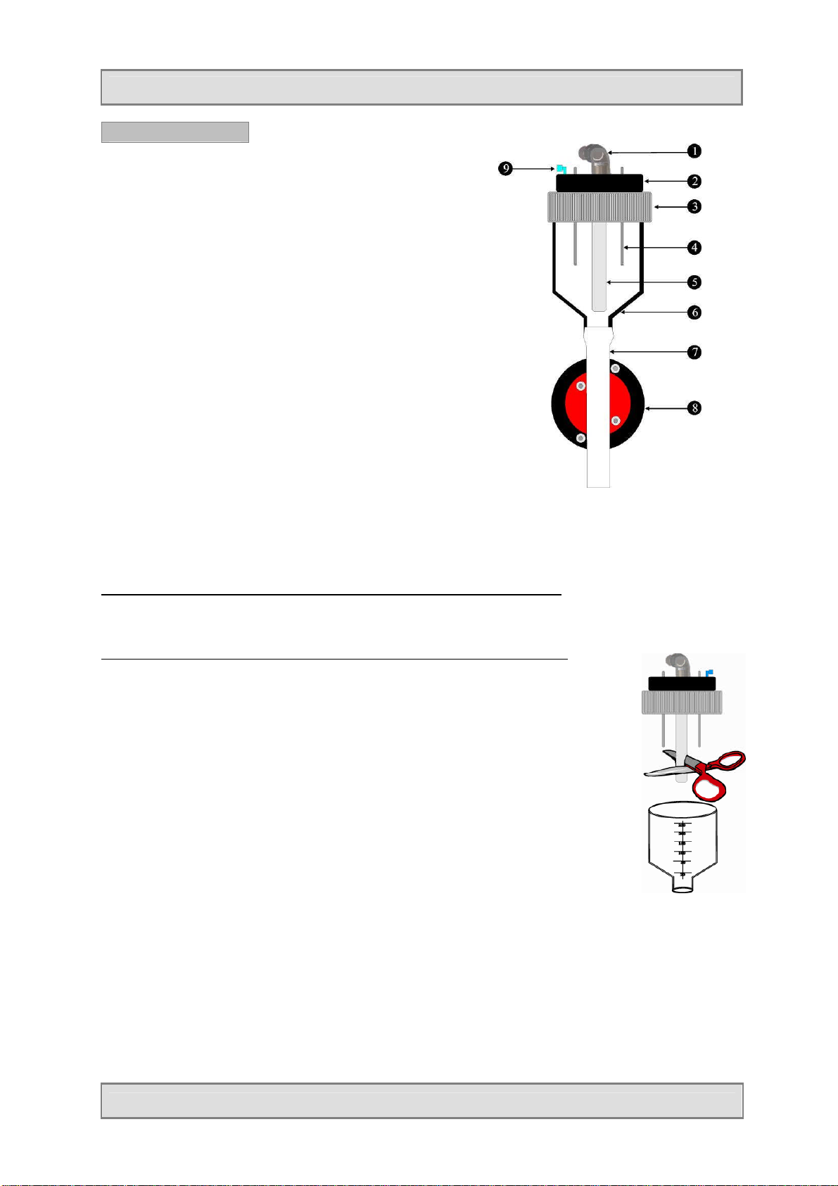
Vacuum sampling system
Metering vessel -structure-
1. Hose connector
2. Flange
3. Screw cap
4. Electrodes
5. Volume control tube
6. Metering vessel
7. Silicone discharge tube
8. Motor-driven pinch-valve
9. Air connection
Cleaning:
- Glass metering vessel: unscrew the screw cap (3) and remove the flange. Now, the metering vessel
together with the silicone discharge tube (7) can be detached.
- Plastic metering vessel: Turn the plastic metering vessel anticlockwise (bayonet fitting) and remove.
Adjustment of sample shot volume at samplers with glass metering vessel:
To adjust the desired sample volume, loosen the knurled screw and displace the volume control tube
vertically.
Adjustment of sample shot volume at samplers with plastic metering vessel:
The sampler is always delivered with the volume control tube in full length.
To adjust the sample shot volume, the volume control tube (5) has to be cut
to length.
Procedure
1. There is a graduation in millilitres on the volume control tube.
2. Remove the metering vessel (6).
3. Cut the volume control tube to the desired length with scissors or a knife.
4. Reinstall the metering vessel (6) and tighten.
5. Check the sample volume by starting a manual sample extraction.
6. Now the device is ready for operation.
Remark: If you need to work with different sample volumes, you can cut to
size several tube pieces. As the volume control tube (5) is only
slipped on the hose connector (1), it is very easy to change the tube.
Page 19 Manual BÜHLER 2000/1029
Page 20
Operation
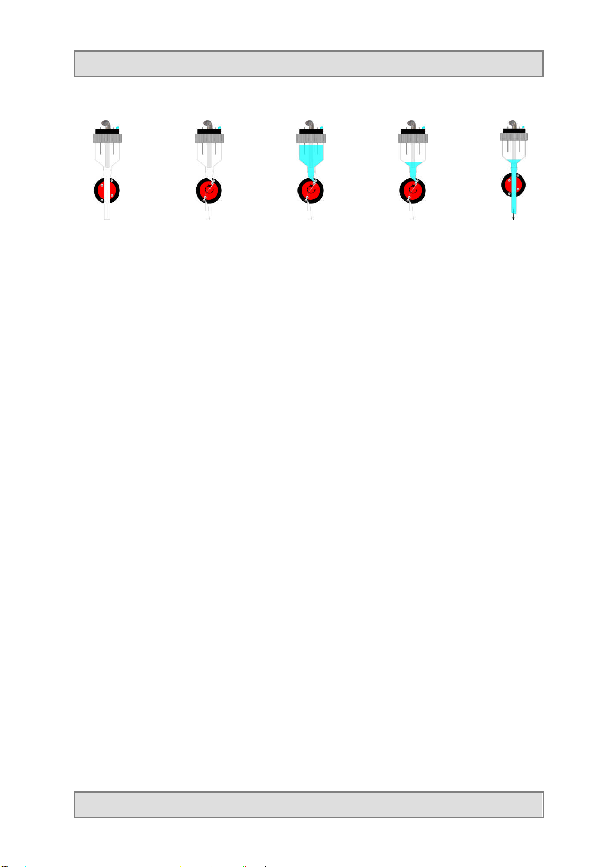
Operation principle:
1. Inoperative
position
Replacement of the silicone discharge hose
The silicone hose (BM69301) is only pushed over the lip of the metering vessel. A hose clamp is not
required. Humidify the hose a little bit, fix it at one point and push it over the lip.
Remark:
Do only use original spare parts from the manufacturer. The use of a wrong hose type can lead to
malfunctions at the system or may even damage the pinch valve!
Remark:
Conductivity of the sample medium
There are two conductive level electrodes in the metering vessel. Their sensitivity can be adjusted in the
service menu. In the factory the electrodes are adjusted to tap water (this adjustment does not have to
be changed under normal operating conditions). Minimum conductivity 50 μS/cm.
Please note that a wrong adjustment can lead to a flooding of the pneumatic system and to the
damage of component parts.
The sampler is not suitable for extraction of distilled water due to low conductivity.
2. Pinch-valve
closes
3. Metering
vessel is filled
up to the
electrodes
4. Dosing system
is aerated
5. Pinch
valve
opens and
sample
drains off
in bottle
Conductivity at 25°C
Rain water 50 μS/cm
Drinking water 500 μS/cm
Waste water 5000 μS/cm (5 mS/cm)
Seawater 50000 μS/cm (50 mS/cm)
ATTENTION:
Wrong operating conditions can lead to malfunctions or may even damage the apparatus. No liability or
claims under guarantee will be accepted in respect of any damage arising from the non-observance of
these operating instructions.
Page 20 Manual BÜHLER 2000/1029
Page 21
Operation
Troubleshooting – vacuum system
If a fault develops in your sampler, we can only provide prompt assistance if you give us the type and
serial number of the apparatus concerned. You will find these data on the type plate.
The more precise your description of the fault is, the better our fault diagnosis will be.
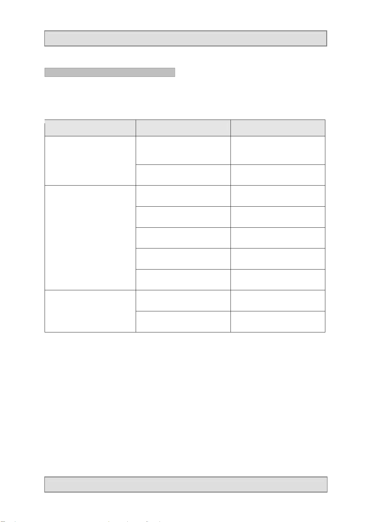
Symptom Possible cause Action
system flooded
Sampler does not extract
samples
pump
Adjustment of conductivity too
low. Distilled water has been
used as sample medium.
No contact to electrodes Check cable connection
System is leaking Check whether all hoses and
Pump/diaphragm defective Check pressure/vacuum of
Metering vessel not tight, no
vacuum
Filling level electrodes bridged Clean electrodes
Valve system/pinch valve does
not function correctly
Defective diaphragm Renew diaphragmNo pressure / vacuum at
Hoses are squeezed Check hoses
Contact service departmentElectrodes do not react,
connections are tight
pump
Check whether metering vessel
is tight (screw cap)
Check valve system/pinch valve
or contact service department
Page 21 Manual BÜHLER 2000/1029
Page 22

Operation
Programming
The menu structure is similar to the index of a computer hard disk and is
split up in main menus and submenus.
Assignment and function of keys:
The apparatus is interactively programmed by the user.
Function of the keys:
Display of help texts (in case of a selection
window the cursor has to be positioned on the
left digit of the selected value to activate the help
text)
Move from one to the next menu Arrow keys
Select the desired menu Enter key
Arrow key
Move within the menu Arrow keys
Selection within the menu Arrow keys
Confirm the choice (is automatically marked
with a √)
Entry of values Arrow keys
Confirm entered values Enter key
Return to higher menu level Back key
Entry of values Numerals 0 - 9
RESET (initialisation to factory settings) Back key
Example:
You want to change a setting, so first press the „ENT“ key.
The cursor is displayed flashing.
Now you can position the cursor on the desired setting by means of the arrow keys.
Enter key
Press key for at
least 10 seconds
Press the „ENT“ key again.
Your choice is now confirmed.
According to the program section you are in, an action is triggered or, if a program is edited, you are
automatically guided to the next menu.
Remark:
In general you can abort every action or step or return to a previous display by means of the back key.
Page 22 Manual BÜHLER 2000/1029
Page 23

Operation
EXAMPLES FOR STANDARD PROGRAMS
1. Programming of a „TIME-PROPORTIONAL“ sampling program
In this sampling mode, a sample is extracted as a function of a programmed time interval.
1.1.4
**********************
PROGRAM NO. 1
TIME
INTERVAL HRS. 0:06
FILLING TIME H 2:00
**********************
1.1.5
**********************
PROGRAM NO. 1
*CHANGE
DELAYED START
START
**********************
2.2.1
**********************
PASSWORD
****
**********************
Selection of the program number:
After having pressed the ENT key, a program number (1 to 6) can be
entered.
Confirm by pressing the ENT key.
Next menu: press the „DOWN“ arrow key.
PROGRAMMING
- Press the ENT key (cursor is displayed flashing)
- Press the „UP“ arrow key twice
- Confirm with ENT
Enter the valid password (factory-set code is 6299).
Remark:
This is only required if a password has been activated in „Setup“->
„System settings“. If not, just press the ENT key and you will get to
the next menu!
If the right password has been entered, you will automatically get to
the next menu.
3.4.1
**********************
MODE
EVENT
*TIME
FLOW ANAL. 0-20 mA
**********************
4.12.1
**********************
INTERVAL
00:10
**********************
5.2.2
**********************
BOTTLE FILLING
*TIME-RELATED
SAMPLE-RELATED
**********************
The selected sampling mode is marked with a star.
If the sampling mode shall be changed, press the ENT key and move
the cursor on the sampling mode TIME to create a time-proportional
program.
Confirm the input by pressing the ENT key.
Enter the sampling interval (hh:mm).
A sample is e.g. extracted every 10 minutes.
Select whether the bottle filling shall be
1. time-dependent or
2. depend on a pre-programmed number of
samples
Page 23 Manual BÜHLER 2000/1029
Page 24

Operation
**********************
6.2.1
**********************
FILLING TIME PER
BOTTLE
2:00H
**********************
5.2.5
**********************
BOTTLE VERSION
*SINGLE BOTTLE
2 x 5,0 L
2 x 10,0 L
**********************
5.2.12
**********************
REPEAT PROGRAM
YES
*NO
**********************
TIME-RELATED bottle filling:
Enter for how long each bottle shall be filled until the distributor
changes to the next bottle.
Example:
Interval: 10 min.
Filling time/bottle: 120 min.
Bottle volume: 2,5 L
That means 12 samples are extracted in 120 min. With a bottle
volume of 2,5 L, the maximum dosing volume per sample is
calculated as follows:
2500:12 200 ml.
If your sampler is equipped with a distributor, select here the
distributor/bottle variant.
If the program shall only run once, select NO.
Selecting „YES“ means continuous operation (the program is
always restarted).
Remark: In that case, the program will run endlessly. So, please
make sure that the bottles are emptied regularly
according to the programming as otherwise they will be
overfilled.
1.1.4
**********************
PROGRAM NO. 1
TIME
INTERVAL HRS. 0:06
FILLING TIME H 2:00
**********************
1.1.5
**********************
PROGRAM NO. 1
CHANGE
DELAYED START
*START
Each programming is completed with this menu to have the possibility to check the program settings of the just created program.
Program No. 1 has been programmed with a time-proportional
program.
To start the program, press the „DOWN“ arrow key.
The just created program can either be
• started immediately
• started with a delay or
• changed
Page 24 Manual BÜHLER 2000/1029
Page 25

Operation
**********************
2. Programming of a „FLOW-DEPENDENT“ sampling program
If this sampling mode is selected, the sampler has to be connected to a flow meter which either
supplies an analogue signal (0/4 - 20mA) or a digital pulse.
The sample extraction is carried out according to this „flow signal“.
The programming of each of the three modes (0 -20 / 4 - 20 / digital) is very similar. Only single
menus are different (depending on the selected settings). The programming of these menus is
depending on the context and thus results from it accordingly.
The following example shows the programming of:
- Flow analogue 0 - 20mA /time-related bottle filling / max. number of samples per bottle limited.
1.1.4
**************************
PROGRAM NO. 2
TIME
INTERVAL HRS. 0:06
FILLING TIME H 2:00
**************************
1.1.5
**********************
PROGRAM NO. 2
*CHANGE
DELAYED START
START
**********************
2.2.1
**********************
PASSWORD
****
**********************
Selection of the program number:
After having pressed the ENT key, a program number (1 to 6) can
be entered.
Confirm by pressing the ENT key.
Next menu: press the „DOWN“ arrow key.
PROGRAMMING
- Press the ENT key (cursor is displayed flashing)
- Press the „UP“ arrow key twice
- Confirm with ENT
Enter the valid password (factory-set code is 6299).
Remark:
This is only required if a password has been activated in „Setup“->
„System settings“. If not, just press the ENT key and you will get
to the next menu!
If the right password has been entered, you will automatically get
to the next menu.
3.4.1
**********************
MODE
EVENT
TIME
*FLOW 0-20 mA
4.10.1
**********************
SAMPLES PER HOUR
AT 20 mA
40
**********************
The selected sampling mode is marked with a star.
If the sampling mode shall be changed, press the ENT key and
move the cursor on the sampling mode FLOW to create a flowdependent sampling program.
Confirm the input by pressing the ENT key.
If „ANALOGUE“ (0/4-20mA) has been selected, enter here how
often samples shall be extracted at a maximum analogue flow
signal.
Example: - Flow analogue 0-20 mA
- At 20 mA 40 samples/hour shall be extracted.
- If there are on an average 10 mA for a period of
1 hour, 20 samples will be extracted.
Page 25 Manual BÜHLER 2000/1029
Page 26

Operation
**********************
5.2.2
**********************
BOTTLE FILLING
*TIME-RELATED
SAMPLE-RELATED
**********************
6.2.1
**********************
FILLING TIME PER
BOTTLE
2:00H
**********************
5.2.3
**********************
NO. OF SAMPLES PER
BOTTLE LIMITED?
*YES
NO
Select whether the bottle filling shall be
1. time-dependent or
2. depend on a pre-programmed number of samples.
At TIME-RELATED bottle filling:
Enter for how long each bottle shall be filled until the distributor
changes to the next bottle.
Example:
Interval: 10 min.
Filling time/bottle: 120 min.
Bottle volume: 2,5 L
That means 12 samples are extracted in 120 min. With a bottle
volume of 2,5 L, the maximum dosing volume per sample is
calculated as follows: 2500:12 200 ml.
In addition to the entry of a bottle filling time you can also limit the
number of samples per bottle.
6.5.1
**********************
MAX. NO. OF SAMPLES
PER BOTTLE
5
**********************
5.2.5
**********************
BOTTLE VERSION
*SINGLE BOTTLE
2 x 5,0 L
2 x 10,0 L
**********************
5.2.12
**********************
REPEAT PROGRAM?
YES
*NO
**********************
Enter the maximum number of samples per bottle.
If your sampler is equipped with a distributor, select here the
distributor/bottle variant.
If the program shall only run once, select NO.
Selecting „YES“ means continuous operation (the program is
always restarted).
Remark: In that case, the program will run endlessly. So,
please make sure that the bottles are emptied
regularly according to the programming as
otherwise they will be overfilled.
Page 26 Manual BÜHLER 2000/1029
Page 27

Operation
1.1.4
**********************
PROGRAM NO. 2
FLOW ANAL. 0-20 mA
SAMP./H AT 20 mA 40
FILLING TIME 2:00
**********************
1.1.5
**********************
PROGRAM NO. 2
CHANGE
DELAYED START
*START
**********************
Each programming is completed with this menu to have the
possibility to check the program settings of the just created
program.
Program No. 2 has now been programmed with a flow-
dependent program.
To start the program, press the „DOWN“ arrow key.
The just created program can either be
• started immediately
• started with a delay or
• changed.
Page 27 Manual BÜHLER 2000/1029
Page 28

Operation
**********************
***************
*******
3. Programming of an „EVENT-PROPORTIONAL“ sampling program
If this sampling mode is selected, the sampler is waiting for an external „event“ signal, e.g. from a
connected pH-meter. A sample is extracted according to the programming as long as the signal is
present. When the signal fades, the sampler waits for the next signal and then fills the next empty
bottle. Which „event“ sample has been filled into which bottle is recorded in the info memory.
1.1.4
**********************
PROGRAM NO. 3
TIME
INTERVAL HRS 0:06
FILLING TIME H 2:00
**********************
1.1.5
**********************
PROGRAM NO. 3
*CHANGE
DELAYED START
START
2.2.1
**********************
PASSWORD
****
**********************
Selection of the program number:
After having pressed the ENT key, a program number (1 to 6) can
be entered.
Confirm by pressing the ENT key.
Next menu: press the „DOWN“ arrow key.
PROGRAMMING
- Press the ENT key (cursor is displayed flashing)
- Press the „UP“ arrow key twice
- Confirm with ENT
Enter the valid password (factory-set code is 6299).
Remark:
This is only required if a password has been activated in „Setup“->
„System settings“. If not, just press the ENT key and you will get to
the next menu!
If the right password has been entered, you will automatically get
to the next menu.
3.4.1
**********************
MODE
*EVENT
TIME
FLOW 0-20 mA
**********************
4.12.1
**********************
INTERVAL
00:10
**********************
5.2.2
**********************
BOTTLE FILLING
*TIME-RELATED
SAMPLE-RELATED
The selected sampling mode is marked with a star.
If the sampling mode shall be changed, press the ENT key and
move the cursor on the sampling mode EVENT to create an
event-related sampling program.
Confirm the input by pressing the ENT key.
Enter the sampling interval (hh:mm).
A sample is e.g. extracted every 10 minutes.
Select whether the bottle filling shall be
1. time-dependent or
2. depend on a preprogrammed number of samples.
Page 28 Manual BÜHLER 2000/1029
Page 29

Operation
**********************
**********************
6.2.1
**********************
FILLING TIME PER
BOTTLE
2:00H
**********************
6.3.1
**********************
SAMPLES PER BOTTLE
1
5.2.5
**********************
BOTTLE VERSION
*SINGLE BOTTLE
2 x 5,0 L
2 x 10,0 L
At TIME-RELATED bottle filling:
Enter for how long each bottle shall be filled until the distributor
changes to the next bottle.
Example:
Interval: 10 min.
Filling time/bottle: 120 min.
Bottle volume: 2,5 L
That means 12 samples are extracted in 120 min. With a
bottle volume of 2,5 L, the maximum dosing volume per
sample is calculated as follows:
2500:12 200 ml.
At SAMPLE-RELATED bottle filling:
Enter the maximum number of samples per bottle. As soon as the
set number of samples has been extracted, sampling into the
respective bottle is terminated.
If your sampler is equipped with a distributor, select here the
distributor/bottle variant.
5.2.12
**********************
REPEAT PROGRAM ?
YES
*NO
**********************
1.1.4
**********************
PROGRAMM NO. 3
EVENT
INTERVAL HRS 00:06
BTL CHANGE EVENT
**********************
1.1.5
**********************
PROGRAM NO. 3
CHANGE
DELAYED START
*START
**********************
If the program shall only run once, select NO.
Selecting „YES“ means continuous operation (the program is
always restarted).
Remark: In that case, the program will run endlessly. So,
please make sure that the bottles are emptied
regularly according to the programming as
otherwise they will be overfilled.
Each programming is completed with this menu to have the
possibility to check the program settings of the just created
program.
Program No. 3 has now been programmed with an event-related
program.
To start the program, press the „DOWN“ arrow key.
The just created program can either be
• started immediately
• started with a delay or
• changed.
Page 29 Manual BÜHLER 2000/1029
Page 30

Operation
**********
************
**********************
**********************
**********************
MAIN MENU (root):
Display
1.1.1
**********************
Vxxxx
1.1.2
**********************
TUESDAY
03 FEBRUARY 2009
09 H 01 MIN 44 SEC
**********************
1.1.3
**********************
OPERATING VOLTAGE
13.8 V
1.1.4
**********************
PROGRAM NO. 1
TIME
INTERVAL HRS 0:06
FILLING TIME H 2:00
**********************
Description
Information menu „Version of firmware“
Information menu „Date/Time“
Time and date are changed in menu „SETUP“.
Information menu „Operating voltage“
Display of internal operating voltage (secondary voltage of power
pack).
Information/selection menu „Program“
In this menu the desired program is selected. The program selected
at the moment and its parameters are displayed. By pressing the
ENT key, the program No. can be changed and one of the 6 user
programs can be selected. The current
program settings of each program are shown.
Remark: This menu is displayed automatically after the last
step of each programming or program change.
Thus you can check immediately whether there are
any programming faults.
**********************
**********************
1.1.5
PROGRAM NO. 1
CHANGE
DELAYED START
*START
1.1.6
MANUAL SAMPLE
EXTRACTION
PROGRAMMING
A program (No. 01-06) selected in menu 1.1.4 can be
• started immediately
• started with a delay or
• changed.
MANUAL MODE
A single sample extraction into any bottle can be triggered
manually.
Page 30 Manual BÜHLER 2000/1029
Page 31

Operation
******
****************
1.1.8
**********************
SETUP
**********************
1.1.9
**********************
MEMORY
**********************
1.1.10
**********************
SERVICE MENU
**********************
CHANGE PROGRAM
SETUP
Enter general settings like
• Date, time
• Language
• Modem
• System settings
MEMORY
Here you can display or delete stored information like:
• Info memory (sampling protocol)
• Bottle memory
• Analogue signal
SERVICE MENU
In the service menu the single components and the inputs can be
tested. However, modifications should only be carried out by
specially trained service personnel.
1.1.5
**********************
PROGRAM NO. 1
*CHANGE
DELAYED START
START
**********************
2.2.1
**********************
PASSWORD
****
**********************
3.4.1
**********************
MODE
EVENT
*TIME
FLOW ANAL. 0-20 mA
A program (No. 01-06) selected in menu 1.1.4 can be
• started immediately
• started with a delay or
• changed.
To avoid manipulations to programs, a password has to be entered
first. The factory-set password is „6299“.
Remark: This is only required if a password has been activated
in „Setup“-> „System
settings“. If not, just press the ENT key and you will
get to the next menu!
(If you enter your own password, we recommend to note it down in
the manual as otherwise there is no more access!)
TIME-related sampling
By pressing the ENT key, the time-proportional sampling mode is
selected.
Page 31 Manual BÜHLER 2000/1029
Page 32

Operation
*****
*****************
3.4.1
**********************
MODE
*EVENT
TIME
FLOW ANAL. 0-20 mA
**********************
4.12.1
**********************
INTERVAL
00:10
**********************
3.4.1
**********************
MODE
TIME
*FLOW ANAL. 0-20 mA
FLOW ANAL. 4-20 mA
**********************
4.10.1
**********************
SAMPLES PER HOUR
AT 20 mA
40
**********************
EVENT-related sampling
By pressing the ENT key, the event-related sampling mode is
selected.
Enter the sampling interval in minutes for sampling modes „TIME“
or „EVENT“.
A sample is e.g. extracted every 10 minutes.
(If you edit a time or event program, the next menu is „BOTTLE
FILLING“)
FLOW ANALOGUE
By pressing the ENT key, the sampling mode „FLOW ANALOGUE“
(analogue signal 0/4 – 20 mA) is selected.
If „ANALOGUE“ (0/4-20mA) has been selected, enter here how
often samples shall be extracted at a maximum analogue flow
signal.
Example:
- Flow analogue 0-20 mA
- At 20 mA 40 samples/hour shall be extracted.
- If there are on an average 10 mA for a period of 1 hour, 20
samples will be extracted.
3.4.1
**********************
MODE
FLOW ANAL. 0-20 mA
FLOW ANAL. 4-20 mA
*FLOW DIGITAL
**********************
4.11.1
**********************
PULSE DIVIDER
25
**********************
5.2.2
**********************
BOTTLE FILLING
*TIME RELATED
SAMPLE RELATED
FLOW DIGITAL
By pressing the ENT key, the sampling mode „FLOW DIGITAL“ is
chosen.
Enter after how many input pulses (potential-free make contacts) a
sample shall be extracted in the sampling mode flow „DIGITAL“.
Example:
At a max. flow 1000 pluses/hour are delivered.
40 samples per hour shall be extracted. Thus the pulse divider
has to be set to 25.
Select whether the bottle filling shall be time-dependent or whether
it shall depend on a pre-programmed number of samples.
Page 32 Manual BÜHLER 2000/1029
Page 33

Operation
**********************
**********************
6.2.1
**********************
FILLING TIME PER
BOTTLE
2:00H
**********************
5.2.3
**********************
NO. OF SAMPLES PER
BOTTLE LIMITED?
*YES
NO
**********************
6.5.1
**********************
MAX. NO. OF SAMPLES
PER BOTTLE
TIME-related bottle filling
Enter for how long each bottle shall be filled until the distributor
changes to the next bottle.
Example:
Interval: 10 min.
Filling time/bottle: 120 min.
Bottle volume: 2,5 L
That means 12 samples are extracted in 120 min. With a bottle
volume of 2,5 L, the max. dosing volume per sample is
calculated as follows: 2500:12 200 ml.
TIME-related bottle filling
In addition to the entry of a bottle filling time you can also limit the
number of samples per bottle.
By means of this menu point a protection against overfilling at flow-
dependent sample extractions is guaranteed.
TIME-related bottle filling
Enter the max. number of samples per bottle.
5
**********************
6.3.1
**********************
SAMPLES PER BOTTLE
1
**********************
5.2.4
**********************
FILLING TIME PER
BOTTLE LIMITED?
*YES
NO
**********************
6.6.1
**********************
MAX. FILLING TIME
PER BOTTLE
2:00H
SAMPLE-related bottle filling
If a sample-related bottle filling has been selected, enter here the
number of samples per bottle.
SAMPLE-related bottle filling
In addition to the entry of a „MAX. NO. OF SAMPLES PER
BOTTLE“, you can also limit the „FILLING TIME PER BOTTLE“.
That means, after expiration of the entered time the distributor
changes to the next bottle.
SAMPLE-related bottle filling
Enter the max. filling time per bottle.
**********************
5.2.5
Select your distributor/bottle variant.
BOTTLE VERSION
12 x 1,0 L
*12 x 2,9 L
24 x 0,4 L
Page 33 Manual BÜHLER 2000/1029
Page 34

Operation
**********************
5.2.12
**********************
REPEAT PROGRAM?
YES
*NO
**********************
START PROGRAM
1.1.5
**********************
PROGRAM NO. 1
CHANGE
DELAYED START
*START
**********************
2.3.1
**********************
DELAYED START
01.01.2009
17:15
Selecting „YES“ means continuous operation (the program is
always restarted).
Remark: In that case, the program will run endlessly. So,
please make sure that the bottles are emptied regularly
according to the programming as otherwise they will be
overfilled.
START
After having pressed the ENT key, move the flashing
cursor on „START“ and confirm again with the ENT key. The
program is started immediately.
DELAYED START
Enter date and time of the delayed program start.
After having pressed the ENT key, the display shows the delayed
start time. The program will be activated automatically at the
entered date/time.
3.3.1
**********************
PROGRAM NO. 1
START 01.01./17:28
BOTTLE 1
< PAUSE WITH ENT >
**********************
3.3.2
**********************
01.01.2009 17:28:17
NEXT SAMPLE 5:43
NEXT BOTTLE 1:59
FLOW 12.2 mA
**********************
After the program has been started successfully, the following is
shown on the display:
1. The selected program
2. Start with date and time
3. The current bottle (or at special programs also e.g. pulse counter
and number of extracted samples)
The possibility to interrupt the program with ENT (pause mode).
Remark: During an active program you can have
displayed a lot of helpful information without
disturbing the program flow or stopping the
running program. You can scroll through the
menus described in the following with the
up/down arrow keys.
If the „down“ arrow key is pressed, date and time, time of the next
sample extraction and time of the next bottle change are displayed.
In time-proportional programs: display in min.
In flow analogue programs: display in %
In flow digital programs: display in pulses.
The flow can be displayed in L/s, cbm/h or mA (to be set in the
menu SETUP).
Page 34 Manual Bühler 2000/1029
Page 35

Operation
******************
****
3.3.3
**********************
01.01.2009 17:28:17
SAMPLES TOTAL
REQUESTED: 1
TAKEN: 0
3.3.4
**********************
01.01.2009 17:28:18
SAMP. CURRENT BTL
REQUESTED: 1
TAKEN: 0
**********************
3.3.5
**********************
PROGRAM NO. 1
INFO MEMORY
*********************
3.3.6
**********************
PROGRAM NO. 1
BOTTLE MEMORY
**********************
By pressing the „down“ arrow key again, the „total“ number of taken
and requested samples of the running program is displayed.
Display of the taken and the requested samples of the current
bottle.
By pressing the ENT key, the menu „INFO MEMORY“ is displayed.
Here you can have a look at the stored messages.
By pressing the ENT key the bottle memory is displayed as follows:
- Number of the bottle
- Date and filling period (from – to)
- Total filling time
- Taken and requested samples.
With the up/down keys you can scroll to each bottle.
3.3.7
**********************
INPUT SIGNALS
FILLING LEVEL 100
FLOW ANAL. 12.2 mA
EVENT 0 / FLOW DIG 0
**********************
3.3.9
**********************
PROGRAM NO. 1
ANALOGUE FLOW
SIGNAL
**********************
3.3.10
**********************
PROGRAM NO. 1
MANUAL SAMPLE
**********************
Display of „Input Signals“:
- Filling level (state of level electrodes. The indicated value has no
dimension!)
- Flow analogue
- Event input
- Flow digital
By pressing the ENT key, the stored mA-signal is shown. The
values displayed are hourly average values.
Here you can trigger manually a single sample extraction into any
bottle (bottle No. can be selected).
Page 35 Manual Bühler 2000/1029
Page 36

Operation
**********************
**********************
**********************
4.6.1
**********************
MANUAL SAMPLE:
BOTTLE 1
**********************
3.3.11
**********************
CHANGE BOTTLE TO
BOTTLE 2
*BOTTLE 3
BOTTLE 4
**********************
4.7.1
**********************
CONTINUING WITH
BOTTLE 3
3.3.12
**********************
PROGRAM NO. 1
PROGRAM SETTINGS
After having pressed the ENT key, you can either confirm the bottle
number already displayed or enter another bottle number. If a
different bottle number is entered, the distributor will change to the
previous bottle after the sample extraction.
This sample is stored in the memory as „manual sample“.
Here you can move the distributor to another bottle.
After having pressed the ENT key, you can select the desired bottle
number with the up/down keys. Thus the program is continued with
this bottle!
This menu is displayed after having pressed the ENT key for
confirmation.
By pressing the ENT key you can have a look at the settings of the
active (running) program.
Scroll with up/down keys.
To leave the menu, press the ESC key.
3.3.13
**********************
PROGRAM NO. 1
SYSTEM SETTINGS
**********************
3.3.1
**********************
PROGRAM NO. 1
START 7.01./17:08
BOTTLE 1
< PAUSE WITH ENT >
*********************
4.1.1
**********************
PROGRAM NO. 1
PAUSE STARTED
PLEASE WAIT
By pressing the ENT key you can have a look at the system
settings.
Scroll with up/down keys.
To leave the menu, press the ESC key.
PAUSE MODE
The pause mode is activated by pressing the ENT key.
Nevertheless the program continues to run according to the
programmed cycle, however, in the background.
During interruptions/pauses you can effect cleaning or maintenance
works.
This message is displayed if the device is in a non-completed cycle
when starting the pause mode. Only after termination of the cycle,
the pause mode can be started.
Page 36 Manual Bühler 2000/1029
Page 37

Operation
**********************
**********************
4.1.2
**********************
PROGRAM NO. 1
PAUSE (29:03)
*CONTINUE PROGRAM
3.3.1
**********************
PROGRAM NO. 1
START 7.01./17:08
BOTTLE 1
< PAUSE WITH ENT >
8.0.1
**********************
PROGRAM NO. 1
ABORT
*YES
NO
**********************
Now you are in the pause mode. The display shows the still
remaining pause time. After expiration of this time, the system will
return automatically to the running program.
The pause mode can be left at any time by pressing the ENT key.
Display shown after the pause mode has been left.
PROGRAM ABORTION
By pressing the ESC key, a running program can be aborted.
However, before the program is aborted, you have to confirm again
with „YES“.
Remark: If the device is in a non completed cycle when
aborting the program, a corresponding message is
displayed. As soon as the sampling cycle is
completed (may take some time), there is an
automatic return to the main menu level.
MANUAL MODE
1.1.6
**********************
MANUAL SAMPLE
EXTRACTION
**********************
2.5.1
**********************
MANUAL SAMPLE
BOTTLE: 1
**********************
MANUAL MODE
A single sample extraction into any bottle can be triggered
manually.
After having pressed the ENT key you can either:
- select the bottle number already displayed by pressing the
ENT key again
or
- enter a new bottle number for the extraction of the manual
sample.
Page 37 Manual Bühler 2000/1029
Page 38

Operation
*****************
*****
**********************
**********************
SETUP
1.1.8
**********************
SETUP
**********************
2.8.1
**********************
DATE TIME
18.01.2009
19:45
2.8.2
**********************
LANGUAGE
FRANCAIS
*ENGLISH
DEUTSCH
2.8.3
**********************
TYPE OF MODEM
*GSM (CELLULAR)
AT-COMPATIBLE
NO MODEM
„Setup“
Enter general settings like
• date, time
• language
• modem
• system settings
Set date and time.
Select the language.
If a modem is installed, enter here the modem type. Any
At-compatible modem or GSM modem can be used.
2.8.4
**********************
SYSTEM SETTINGS
CHANGE
**********************
Here you can change the system settings.
Remark: Modifications should only be carried out by specially
trained service personnel.
Wrong adjustments can lead to malfunctions or
may even damage the apparatus!
Page 38 Manual Bühler 2000/1029
Page 39

Operation
**********************
MODEM SETTINGS
2.8.3
**********************
MODEM
*GSM (CELLULAR)
AT-COMPATIBLE
NO MODEM
**********************
3.9.5
**********************
GSM-PIN
PIN:****
REPEAT: ****
**********************
3.9.1
**********************
INITIALIZE MODEM
*START
3.9.2
**********************
DEVICE
INDENTIFICATION
Select the type of modem.
Attention: Please make sure that the baud rate setting of CPU
and modem is identical!
Enter the corresponding GSM Pin No. and repeat it once to confirm.
Remark: The PIN check only serves for authorization. The PIN
cannot be changed here.
Start the initialization of the modem by pressing the ENT key.
If the system does not recognize the modem, an „error message“ is
displayed. If this is the case, check the installation and the
configuration of the modem (see modem manual).
For identification you can enter a name for the sampler by pressing
the ENT key.
The keyboard of the control unit is used in the same way as the
keys of a portable phone:
SAMPLER 1 >
**********************
3.9.3
**********************
SENDING OF SMS
ACTIVE:
*YES
NO
**********************
4.15.1
**********************
NUMBER FOR SMS:
49174356984 >
**********************
1 = 1 2 = abc2 3 = def3
4 = ghi4 5 = jkl5 6 = mno6
7 = pqrs7 8 = tuv8 9 = wxyz9
0 = - _@ .0
Select YES if the alarm messages shall be sent via SMS.
Press the ENT key to enter the SMS number.
If you entered a wrong number, press the left key to delete.
Remark: Enter the country code without 0 or + !
Page 39 Manual Bühler 2000/1029
Page 40

Operation
**********************
**********************
**********************
**********************
**********************
4.15.2
**********************
SEND SMS IN CASE OF:
SAMPLING (MAN)
*SAMPLING (PRG)
SAMPLING (REMOTE)
**********************
4.15.3
**********************
SEND TEST SMS
*NOW
3.9.4
**********************
SENDING OF FAX
ACTIVE:
*YES
NO
**********************
4.16.1
**********************
FAX NUMBER:
By pressing the ENT key all the messages which can be sent are
shown. With the up/down keys you can scroll. Press the ENT key
once to mark and to activate a message. If the ENT key is pressed
twice the marking is deleted again.
All messages marked with a star will be sent via SMS.
To check immediately whether the system is working correctly you
can send a test SMS.
Alternatively to the SMS you have the possibility to send the
messages to a fax apparatus.
Proceed as described above (SMS)!
Enter the fax number.
If you entered a wrong number, press the left key to delete.
4974719848144 >
4.16.2
**********************
FAX REPORT
SYSTEM SETTINGS
PROGRAM REPORT
*TEST PAGE
4.16.3
**********************
SEND PROGRAM
REPORT AUTOMAT.?
YES
*NO
5.7.1
**********************
APPEND INFO MEMORY
TO PROG. REPORT?
YES
*NO
Remark: Enter the country code without 0 or + !
To check immediately whether the system is working correctly you
can send a test fax message.
In addition to the alarm messages it is also possible to send the
program report (stored program data).
Possibility to send also the contents of the information memory.
Page 40 Manual Bühler 2000/1029
Page 41

Operation
**********************
6.10.1
**********************
DELETE INFO MEMORY
AT PROGRAM START?
YES
*NO
**********************
CHANGE SYSTEM SETTINGS
2.8.4
**********************
SYSTEM SETTINGS
CHANGE
**********************
3.10.1
**********************
PASSWORD
****
Select whether the info memory shall be deleted at the program
start.
Here you can change the system settings
Remark: Modifications should only be carried out by specially
trained service personnel.
Wrong adjustments can lead to malfunctions or may
even damage the apparatus!
This section is protected by a password. The factory-set password
is 6299 (the factory always activates the
password).
The password can also be changed.
**********************
4.17.1
**********************
PRE-PURGE
PRIOR TO SAMPLING
5.0 s
**********************
4.17.2
**********************
POST-PURGE
AFTER SAMPLING
0.0 s
**********************
4.17.3
**********************
AERATION TIME
5.0 s
DEACTIVATION:
To deactivate the password enter 0000 !
Set the purging time prior to each sample extraction. This is
recommended in order to remove possible deposits in the suction
aperture.
Set the purging time after each sample extraction (if the suction
hose is laid with a continuous fall, you can leave it at 000).
This purging is recommended if the suction hose is laid horizontally
in order to blow out remaining water.
Set the aeration time: time between filling level signal and opening
of pinch-valve in order to fill the sample into the bottle.
Page 41 Manual Bühler 2000/1029
Page 42

Operation
4.17.4
**********************
MAX. SUCTION TIME
60.0 s
**********************
4.17.6
**********************
PINCH-VALVE OPEN
3.0 s
**********************
4.17.7
**********************
PINCH-VALVE PAUSE
2.0 s
**********************
Limitation of suction time. After expiration of this time, the suction
process is terminated even if no water has been drawn off, that
means that there was no signal from the level electrodes. If this is
the case, a second attempt is made. That means after expiration of
the suction time, the line is purged again and water is drawn off. If
this second attempt fails, too, the message „ERROR SUCTION“ is
displayed which is resulting in a malfunction message (utilizable
signal if an optional relay is installed).
However, the sampler continues to function even after a
malfunction message. The program is not aborted for that
reason!
Possibility to correct the return time of the valve if it does not stand
straight. This is important for the pinch-valve to close correctly
during a sample extraction.
The pinch-valve first only opens 1/3. Here you can input the time
until it opens completely.
This is recommended if distributor variants are installed, as the
biggest part of the sample drains off more slowly. Apart from that,
the sample is discharged more gently.
4.17.9
**********************
CONDUCTIVITY
300
**********************
4.17.10
**********************
PUMPING CAPACITY
50 %
**********************
4.17.11
**********************
PINCH-VALVE POWER
60 %
**********************
Adjust the sensitivity of the conductivity electrodes.
However, this value has no dimension!
Make sure that the system is neither adjusted too insensitive (leads
to a flooding) nor too sensitive (there is a permanent signal and thus
no more sample extraction).
A lower value (e.g. 200) means more sensitive or quicker response
of the electrodes.
A higher value (e.g. 300) means more insensitive or slower
response of the electrodes.
Adjust the pumping capacity in %
The adjusted pumping capacity does not influence the suction
height but only the average suction speed when drawing-off the
sample.
The lower the pumping capacity, the longer the service life of the
pump.
Adjust the pinch-valve power in %.
Modifications should only be carried out by
service personnel!
Page 42 Manual Bühler 2000/1029
Page 43

Operation
**********************
**********************
4.17.12
**********************
VALVE SYSTEM
POWER
40 %
**********************
4.17.20
**********************
PULSE DURATION
FLOW DIGITAL
50 [ms]
4.17.21
**********************
FLOW UNIT
mA
m3/h
*L/s
5.9.1
**********************
FLOW
AT 20mA
Adjust the valve system power in %.
Modifications should only be carried out by service
personnel!
Input the required pulse duration of the digital flow signal. According
to our example, the signal would have to be present for 50 ms in
order to be utilizable for the control.
Select how flow shall be displayed after the program start.
Press the ENT key to scale the flow signal (l/s or m3/h).
Enter how the flow signal (mA) shall be scaled. To do this, just enter
the flow at 20 mA in L/s or m3/h. The scaling is done automatically
within the selected range.
1 L/s
**********************
EXTENDED PROGRAM SETTINGS
4.17.22
**********************
EXTENDED PROGRAM
SETTINGS ACTIVE
YES
*NO
**********************
4.17.23
**********************
PRG. SAMPLING DELAY
RANDOM TIME
*FIXED TIME
NONE
**********************
EXTENDED PROGRAM SETTINGS
The extended program settings offer a more extensive
programming.
The description of the individual functions can be found in appendix
-A-.
By selecting YES, the extended program functions are
activated and thus displayed and can be selected when
programming.
We recommend an activation only if really required as the structure
will get very complex!
Possibility to delay each sample extraction by the time entered.
• Fixed time: The sample extraction will always be
• Random time: If you enter e.g. 10 min., the sample
delayed by e.g. 5 min.
extraction will be delayed at random within
the range of 0 to 10 min.
Page 43 Manual Bühler 2000/1029
Page 44

Operation
**********************
**********************
****
******************
4.17.24
**********************
CALIBRATION OF
ANALOGUE SIGNAL
5.11.1
**********************
NON-CALIB. V 12.207
CALIB. VAL. 12.207
FACTOR: 1.0000
ENT=OK ESC=ABORT
**********************
4.17.25
**********************
INFO MEMORY
INFORMATION
SETTINGS
*RECORDING
CALIBRATION OF ANALOGUE SIGNAL
To display the calibration menu, press the ENT key.
Here you can calibrate the analogue signal by means of a reference
signal.
Use the arrow keys to set the values:
• up/down = rough adjustment (steps with 10)
• left/right = fine adjustment (steps with 1).
The „calibrated“ value is set immediately.
Press 0 to reset to factor 1.0000.
Confirm the values by pressing the ENT key!
Enter which data and how it shall be registered in the info memory.
5.14.1
**********************
RECORD:
*SAMPLING (MAN)
SAMPLING (PRG)
*SAMPLING (REMOTE)
**********************
5.13.1
**********************
DELETE INFO MEMORY
AT PROGRAM START?
YES
*NO
**********************
5.12.1
**********************
INFO MEMORY
SIZE: 1100
ENTRIES: 26
**********************
4.17.27
**********************
DIGITAL OUTPUTS
*OUTPUT 1
OUTPUT 2
OUTPUT 3
Info memory - Recording
By pressing the ENT key, a list of all possible messages is
displayed. Scroll with keys.
By pressing the ENT key, the desired messages are marked with a
*. Pressing the ENT key again deletes the marking.
All messages marked with a star will be recorded.
Info memory - Settings
To delete the info memory at each program start, select „YES“.
By pressing „NO“, the info memory is filled with data according to
the FIFO (first in, first out) principle. That means as soon as the
memory is full, the oldest data is overwritten.
Info memory - Information
Here you can see the memory size (number of entries) and check
how many entries have already been stored.
Eight digital outputs are available. Each of them can be selected
and configured.
Page 44 Manual Bühler 2000/1029
Page 45

Operation
5.16.1
**********************
DIGITAL OUTPUT 1:
*PROGRAM ACTIVE
PROGRAM COMPLETED
BOTTLE CHANGE
**********************
4.17.28
**********************
DIGITAL INPUTS
*INPUT 1
INPUT 2
INPUT 3
**********************
5.17.1
**********************
DIGITAL INPUT 1:
*START PROGAM
STOP PROGRAM
SAMPLING
**********************
4.17.31
**********************
BAUD RATE RS232
38400
57600
*115200
**********************
4.17.32
**********************
CHANGE PASSWORD
6299
**********************
If e.g. output 1 is selected, the opposite menu is displayed.
By pressing the ENT key, a list of possible signals is displayed.
Scroll with keys . Press ENT to mark the desired signal(s) with
a *. Pressing the ENT key again deletes the marking.
Remark: See appendix for all selectable
messages.
Three digital inputs are available. Each of them can be selected and
configured.
If e.g. input 1 is selected, the opposite menu is displayed.
By pressing the ENT key, a list of choices is shown. Scroll with keys
. Press the ENT key to mark the desired choice (action that
shall be triggered by an incoming signal) with a *. Pressing the ENT
key again deletes the marking.
Here you can adjust the Baud Rate of the RS232 interface.
Remark: In case of operation by modem, the baud rate set in this
menu has to be identical with the baud rate of the
modem used!
ACTIVATION / DEACTIVATION OF PASSWORD
Here you can determine your own password. By pressing the ENT
key, a 4-digit code can be input. Press the ENT key again after the
entry. Now, the code is activated! If you want to deactivate it again,
input 0000 and confirm with ENT!
Remark: In any case, note down the input code as otherwise
you will have no more access to the protected program
sections!
MEMORY
1.1.9
**********************
MEMORY
**********************
Here you can have a look at the stored information.
Remark: By means of the optional RS232 interface kit you
can also read out the data to a computer.
Page 45 Manual Bühler 2000/1029
Page 46

Operation
**********************
**********************
2.9.1
**********************
INFO MEMORY
DELETE
*SHOW
**********************
3.12.1
**********************
18.01.09 19:34 -> 2
SAMPLING (MAN)
18.01.09 19:350
BOTTLE CHANGE
**********************
2.9.2
**********************
BOTTLE MEMORY
3.13.1
**********************
BOTTLE 1
19.01.09 18:50-19:04
12 MINUTES
S. REQ/TAKEN 13/13
**********************
Here you can have displayed or delete the info memory. To show
the stored data, press the ENT key. Scroll with the up/down keys.
The following data is stored in the INFO MEMORY:
• Program start and end
• Bottle change with date and time
• Malfunction messages (e.g. voltage loss....etc.)
• Event start and end.
Exemplary display for stored messages. Each entry is stored with
date and time.
The display always shows the latest entry.
- To see the oldest entry, press the left arrow key.
- To see the latest entry, press the right arrow key.
With the up/down keys you can scroll. From any entry you can
return to the oldest entry by pressing the „ENT“ key.
Stored protocol of bottle filling. Press the ENT key to see the
contents of the bottle memory.
With the up/down keys you can scroll to the different bottle
numbers.
The following information is displayed:
• Bottle number
• Date and filling period (from – to)
• Total filling time
• Requested and taken samples.
2.9.4
**********************
ANALOGUE FLOW
SIGNAL
12.2 mA
*STORED VALUES
3.15.1
**********************
18.01.09 23-00 12.2
19.01.09 00-01 12.2
19.01.09 01-02 ----
19.01.09 02-03 ----
**********************
2.9.5
**********************
2ND ANALOGUE INPUT
FORMAT
*INFO
Display of the stored ANALOGUE FLOW SIGNAL.
Press the ENT key to see the contents of the analogue
signal memory.
The analogue signal is stored as an hourly average value.
A second analogue input is available which can also be stored in
the memory. Here you can enter the storage interval.
Page 46 Manual Bühler 2000/1029
Page 47

Operation
3.17.1
**********************
2ND ANALOGUE INPUT
VALUE: 0.0 mA
INTERVAL: 10 min.
MEM SIZE: 55 days
**********************
3.16.1
**********************
RECORDING INTERVAL:
5 MINUTES
*10 MINUTES
15 MINUTES
**********************
SERVICE MENU
1.1.10
**********************
SERVICE MENU
If „Info“ is selected, the settings of the 2nd analogue input are
displayed.
The memory is filled with data according to the FIFO (first in, first
out) principle. The display always shows the average value of the
preceding time interval. That means, if the interval is e.g. set to 10
min., an average value is stored every 10 minutes (example: x: 00,
x: 10, x: 20 etc.)
Select the recording interval. The memory size (number of days) is
depending on the selected recording interval. The table shows the
memory capacity in days:
1 minute 5 days
5 minutes 28 days
10 minutes 56 days
15 minutes 85 days
30 minutes 170 days
60 minutes 340 days
In the service menu the single components as well as the inputs
and outputs can be tested.
Remark: Modifications should only be carried out
by specially trained service personnel.
**********************
2.10.1
**********************
PASSWORD
****
**********************
3.18.1
**********************
DIAPHRAGM PUMP
ON
*OFF
**********************
3.18.4
**********************
PINCH-VALVE
OPEN
CLOSED
*OFF
**********************
This section is protected by a password. The factory-set password
is 6299.
The password can be changed or deactivated (enter 0000) in
„Setup“-> „System settings change“.
After selection with ENT and after pressing the key (selection of
ON), the diaphragm compressor can be started by pressing ENT
again. The compressor is running until it is switched off again by
pressing the ENT key.
After selection with ENT, the pinch-valve can either be moved in the
direction OPEN or in the direction CLOSED. By pressing the ENT
key two times running, the pinch-valve can be stopped in any
position.
Remark: According to the selected direction, the pinch-
valve always runs up to the limit stop, that
means it has to be stopped manually in the
desired position!
Page 47 Manual Bühler 2000/1029
Page 48

Operation
**********************
**********************
**********************
**********************
3.18.5
**********************
VALVE SYSTEM
PRESSURE
VACUUM
*OFF
**********************
3.18.8
**********************
DISTRIBUTOR MOTOR
ON
*OFF
**********************
3.18.11
**********************
DISTRIBUTOR
24 x 1,0 L
BOTTLE: 1
3.18.15
**********************
SELF-TEST
DISPLAY PROTOCOL
*START TEST
After selection with ENT, the valve system can either be moved in
the direction pressure or in the direction vacuum. By pressing the
ENT key two times running, the valve can be stopped in any
position.
Remark: According to the selected direction, the valve
system always runs up to the limit stop, that
means it has to be stopped manually in the
desired position!!!
After selection with ENT, the distributor motor can be switched on or
off.
In this menu you can check the functioning of the motor. A position
control is not possible!
Possibility to move the distributor on any bottle position in order to
effect a position control.
With this function a system check is possible.
Remark: A system check must only be carried out by
specially trained service personnel!
3.18.16
**********************
DISPLAY EACH STEP OF
SAMPLING PROG.
*START
3.18.18
**********************
MODEM DIAGNOSIS
(1-9)
3.18.19
**********************
INPUTS
1 2 3 4 5 6 7
0 0 0 0 0 0 0
**********************
DISPLAY EACH STEP OF PROGRAM
You can have run a whole sampling cycle step by step to check
whether each component is functioning correctly.
After each step the program is stopped until you press ENT again.
Thus it is easy to check each single component (motor, valves, etc.)
which facilitates the fault diagnosis.
With keys 1 to 9 you can send different commands for
diagnosis to the modem. For more information, see
operating manual of the modem!
Here you can check the inputs. The input is o.k. if the selected
channel shows „1“ as long as there is a signal.
Page 48 Manual Bühler 2000/1029
Page 49

Operation
**********************
3.18.20
**********************
OUTPUTS
OUTPUT 1
OUTPUT 2
OUTPUT 3
3.18.21
**********************
INPUT SIGNALS
FILLING LEVEL 100
FLOW ANAL 12.2 mA
EVENT 0 / FLOW DIG 0
**********************
Here you can check the outputs.
If you press ENT and a relay is connected, you can check whether
the output is o.k.
The status of various inputs can be inquired.
Example:
• FILLING LEVEL 250 (or higher)
Level electrodes are bridged (the respective value is directly re
lated to the conductivity. However, the indicated value has no
dimension)
• FLOW ANALOGUE 12 mA
There are 12 mA at the analogue input.
• EVENT 0 (1)
0 = There is no event signal
1 = There is an event signal
• FLOW (digital) 0 (1)
0 = No pulse
1 = Pulse (digital)
Page 49 Manual Bühler 2000/1029
Page 50

Operation
APPENDIX A - Special programming
EXTENDED PROGRAM SETTINGS (displayed when programming)
5.2.1
**********************
BOTTLE FILLING
*COMB. TIME/SAMPLE
TIME-RELATED
SAMPLE-RELATED
**********************
6.2.2
**********************
ADJUST TIME FOR
CHANGE TO BOTTLE 1?
*YES
NO
**********************
Only at flow analogue/digital mode!
Select the COMBINED MODE „TIME/SAMPLE
RELATED“ by pressing the ENT key. Press enter again to input a
number of samples per bottle and a bottle filling time (press ENT
again). The bottle change is depending on which setting (time or
number of samples) is reached first.
ADJUST TIME FOR CHANGE TO BOTTLE 1
With this function a fixed allocation between bottle number and
time of the day is achieved!
The program start is possible at any time, but with the condition
that the sampler changes into a 24-hour cycle with bottle No. 1 at
a desired time.
Contrary to the delayed program start, the sample extraction is
started immediately after the program start.
Remark:
This function is recommended if a program repeat has been
programmed as the change to bottle No. 1 after the program start is
always effected at the entered time in a 24-hour rhythm. If the
program has been started without program repeat, the bottle
change is effected as described and the program is terminated after
12 bottles have been filled.
7.1.1
**********************
START TIME FIRST
BOTTLE
00:00
**********************
A detailed description (example) can be found on the next page.
Enter the time at which the sampler shall change to bottle No. 1.
Page 50 Manual Bühler 2000/1029
Page 51

Operation
**********************
Example:
• Program settings:
- Start time of first bottle: 00:00 h
- Bottle change: 2 hours
- Number of bottles: 12 bottles
If the function „Start time 1st bottle“ has been chosen and the program is e.g. started at 08.30 h (=
real time), the program flow is as follows:
1st step: Distributor synchronizes to bottle No. 1.
2nd step: By way of calculation the program start is effected in the past, at the time entered in
the menu (that is 00.00 h).
Thus the program is immediately in the desired 24-hour cycle.
3rd step: Proceeding from the current time (08:30 h), the sampler now automatically
calculates the bottle/distributor position on which the sample extraction has to be
started in reality in order to ensure the bottle change to bottle No. 1 at 00:00 h.
4th step: The distributor moves to the calculated bottle position (according to our example
bottle No. 5)
5th step: The sample extraction is started with this bottle.
According to our example, the sample extraction would be started at 8:30 h with bottle No. 5.
Bottle No. 5 would be filled for further 1,5 hours.
Bottle filling time from/to Bottle
00:00 - 02:00 1 Calculated program start
02:00 - 04:00 2
04:00 - 06:00 3
06:00 - 08:00 4
08:00 - 10:00 5 Real program start in this period (8:30).
10:00 - 12:00 6
12:00 - 14:00 7
14:00 - 16:00 8
16:00 - 18:00 9
18:00 - 20:00 10
20:00 - 22:00 11
22:00 - 00:00 12
00:00 - 02:00 1 Bottle change to bottle No. 1
5.2.6
**********************
NUMBER OF SERIAL
SAMPLES
SERIAL SAMPLES
At each sample extraction a series of samples (according to the
entered value) is taken successively. This entry enables the
extraction of a big sample volume within a short time.
03
**********************
5.2.7
Select on which bottle the program shall be started.
**********************
FIRST BOTTLE
01
Page 51 Manual Bühler 2000/1029
Page 52

Operation
**********************
5.2.8
**********************
LAST BOTTLE
LIMITATION?
*YES
NO
**********************
6.7.1
**********************
LAST BOTTLE
08
5.2.9
**********************
SAMPLING PAUSE
00:60 H
**********************
Possibility to limit the number of bottles to be filled.
Example: Your sampler has 12 bottles but you would like the
program cycle to be stopped always after the eighth
bottle. The remaining bottles will always be empty!
Enter a sampling pause between the single bottles.
Example: -Number of bottles 12
-Filling time 60 min.
-Sampling pause 60 min.
After the program has been started, samples are filled into the first
bottle for a period of 60 min. Then the program is interrupted for 1
hour (=sampling pause). Thereafter the distributor changes to the
second bottle and again samples are extracted for a period of 1
hour and so on.
5.2.10
**********************
COMBINED EVENT
SAMPLING
*YES
NO
**********************
6.8.1
**********************
INTERVAL COMBINED
EVENT SAMPLING
00:03H
**********************
6.8.3
**********************
BOTTLE FILLING TIME
COMB. EVENT
SAMPLING
01:00H
**********************
COMBINED EVENT SAMPLING
This function enables an overriding event-related sample
extraction independent of the previously programmed sampling
modes TIME or FLOW.
An event can e.g. be that a limit value (pH) is exceeded. The pH
measuring instrument thus delivers the signal necessary for the
sampler to change to the event-related sampling mode!
Example: You have started a time-proportional program according
to which a sample is extracted every 10 minutes. If the combined
event-dependent sampling mode has been activated and the device
receives an event pulse, the distributor immediately changes to the
next (empty) bottle and the event-dependent sample extraction is
started. The event sampling is carried out according to the adjusted
parameters: „Interval combined event sampling“ and „Bottle
filling time comb. event sampling“.
According to the example this would mean:
Sampling interval: 3minutes
Filling time per event bottle: 1 hour
The sampler extracts samples according to these parameters until
the event signal is released. Then the sampler continues to carry
out sample extractions according to the previously selected
sampling mode!
Page 52 Manual Bühler 2000/1029
Page 53

Operation
**********************
**********************
**********************
**********************
5.2.11
**********************
DEFINE SPECIAL DAYS?
*YES
NO
**********************
6.9.1
**********************
SPECIAL DAYS 1
THURSDAY
FRIDAY
*SATURDAY
6.9.2
**********************
SPECIAL DAYS 1:
SPLS/HOUR AT 20mA
(STANDARD: 12)
010
Only at flow analogue/digital mode
Possibility to program that on special days (to be defined by the
user) the sample extraction is effected according to different
program settings.
Example:
At week-ends (Saturday, Sunday) the sample flow is much lower,
that means a lower frequency of flow signals (pulses) and thus a
smaller sample volume. However, if you would like to have almost
the same sample volume as on weekdays, you can select this
function and
a) define the special days freely
b) define the pulse divider or number of samples at a max.
analogue signal for these days.
Press the ENT key and scroll with the up/down keys.
Press the ENT key again to mark the desired day(s) with a star. The
special programming is valid for each day marked with a star “*”.
Analogue signal
Enter the desired number of samples per hour at 20 mA.
6.9.3
**********************
SPECIAL DAYS 1:
PULSE DIVIDER
(STANDARD: 1)
010
6.9.4
**********************
SPECIAL DAYS 2
*SUNDAY
MONDAY
TUESDAY
Digital pulse
Enter the desired pulse divider.
Possibility to have a further special days´ setting for example for
holidays etc. The programming procedure is the same as at
„Special days 1“.
Page 53 Manual Bühler 2000/1029
Page 54

Operation
SPECIAL DISPLAY/MALFUNCTION MESSAGES
The following messages are utilizable signals which can be wired as collective malfunction message
or separately to (optional) relays.
After the relay has been switched, you can have it released again by pressing the key. The program
continues the cycle. At the same time the malfunction message on the display is deleted.
Remark: Each of the described messages can be logged with date and time in the INFO
MEMORY if it has been activated in: Setup->System Settings Change->Info
Memory->Recording
1. Error SUCTION
********************
PROGRAM NO. 02
START 12.03.09/08:00
ERROR SUCTION
PAUSE WITH ENT
********************
********************
PROGRAM NO. 02
START 12.03.09/08:00
ERROR ELECTRODES
PAUSE WITH ENT
********************
The device tried two times running to extract a sample, however,
without success. Thereafter the opposite message is displayed.
Possible causes could be that e.g. the suction hose has not been in
the water, has been clogged or that there has not been any water.
Anyway, the program is continued and the sampler tries again to
extract a sample according to the programming.
2. Error ELECTRODES
If the apparatus displays this message immediately after it has
started to draw-off the sample, the level electrodes are either so
dirty that
no conductivity can be measured or
the electrodes are permanently bridged.
Furthermore it is possible that the value „conductivity“ has
been adjusted too sensitive in the service menu so that there
is a permanent signal.
********************
PROGRAM NO. 02
START 12.03.09/08:00
VOLTAGE LOSS
PAUSE WITH ENT
********************
********************
PROGRAM NO. 02
START 12.03.09/08:00
ERROR DISTRIBUTOR
PAUSE WITH ENT
********************
3. Error VOLTAGE LOSS
This message is shown (as soon as the voltage is back again) if
there is a voltage loss during a running program.
The apparatus resumes the program at the point where it should
have been according to the programmed cycle.
Depending on the duration of the voltage loss, the device also
automatically changes to the „right“ bottle.
4. Error DISTRIBUTOR
This message is displayed if there is a malfunction at the
distributor!
Page 54 Manual Bühler 2000/1029
Page 55

Operation
EXTENDED MALFUNCTION MESSAGES
3.5 MAX SAMP/BTL REACHED If the maximum number of samples/bottle is exceeded.
3.7 ERROR ANAL. SIGNAL At flow-dependent mode if there is no more analogue
signal.
3.8 MAX FILL. TME REACHED If the maximum bottle filling time is exceeded.
MESSAGES
The following messages can be stored in the info memory if they are activated in: Setup->
System Settings Change->Info Memory->Recording
4.2 SAMPLING (MAN)
4.3 SAMPLING (PRG)
4.4 SAMPLING (REMOTE)
4.5 SAMPLING (EVENT)
4.6 ERROR SUCTION
4.7 ERROR ELECTRODES
4.8 ERROR DISTRIBUTOR
4.9 MAX SAMP/BTL REACHED
4.10 PROGRAM STARTED
4.11 PROGRAM COMPLETED
4.12 PROGRAM PAUSE
4.13 PROGRAM CONTINUED
4.14 PROGRAM RESTART
4.15 BOTTLE CHANGE
4.17 SAMP. TAKEN (PRG)
4.18 SAMP. REQ. (PRG)
4.19 EVENT START
4.20 EVENT END
4.21 VOLTAGE LOSS FROM
4.22 VOLTAGE LOSS UNTIL
4.23 SAMP. TAKEN (BTL)
4.24 SAMP. REQ. (BTL)
4.25 ERROR ANAL. SIG FROM
4.26 ERROR ANAL. SIG ´TIL
4.28 SYSTEM START
4.29 MAX. FILLING TIME
Page 55 Manual Bühler 2000/1029
Page 56

Operation
DIGITAL INPUTS / OUTPUTS
You can assign the following selectable messages to the digital inputs or outputs:
Setup-> System Settings -> Digital Outputs / Digital Inputs
Remark: The messages are related to the type of sampling system. Only the messages related to
your sampler type are displayed!
DIGITAL OUTPUTS:
14.2 PROGRAM ACTIVE
14.3 PROGRAM COMPLETED
14.4 BOTTLE CHANGE
14.5 SAMPLING
14.6 Error: ALL
14.7 Error: ELECTRODES
14.8 Error: SUCTION
14.9 Error: DISTRIBUTOR
14.10 Error: MAX. SAMP/BTL.
14.12 Error: ANALOGUE SIGNAL
14.13 Error: VOLTAGE LOSS
14.16 Counter: SAMPLING OK
14.17 Counter: SAMPLING ERROR
14.18 Counter: DIGITAL PULSE
DIGITAL INPUTS:
15.2 START PROGRAM
15.3 STOP PROGRAM
15.4 SAMPLING
15.5 BOTTLE CHANGE
Page 56 Manual Bühler 2000/1029
Page 57

Operation
Rotating distributor
1. Geared motor
2. Safety clutch
3. Split washer for position 1 recognition
4. Forked light barrier
5. Drive axle
6. Distributor tray
7. Discharge
Remark: position 1
After the program start, the distributor always searches for position 1. Position 1 is recognised by
means of a forked light barrier.
In case of a malfunction (voltage loss, battery change) during a running program, the distributor first
always runs over position 1 again so that a correct positioning is guaranteed.
ATTENTION:
The distributor is driven by a geared motor. The distributor must under no circumstances be turned by
hand! In case of non-observance, the gear will be damaged!
Cleaning
To clean the distributor tray, loosen the screw connection in the middle and pull out the tray.
Page 57 Manual Bühler 2000/1029
Page 58

Operation
Troubleshooting - distributor
If a fault develops in your sampler, we can only provide prompt assistance if you give us the type and
serial number of the apparatus concerned. You will find these data on the type plate.
The more precise your description of the fault is, the better our fault diagnosis will be.
Symptom Possible cause Action
No function Connections
Water penetrated in distributor
drive
Program cannot be
started
Distributor is continuously
turning
Wrong positioning of
distributor
Wrong distributor has been
entered
Forked light barrier defective
Pulse generator defective
Interfering pulses.
Pulse generator does not
function correctly
Check connections
Dismantle distributor head
and check for water
penetration.
Contact service department
Correct entry
Contact service department,
return defective part if
necessary
Contact service department
Page 58 Manual Bühler 2000/1029
Page 59

Maintenance
Maintenance
The apparatus should be cleaned regularly in accordance with the degree of contamination present. In
view of the quality of samples, we recommend to clean thoroughly especially the wetted parts like
dosing unit, electrodes, distributor, bottles and inlet hose.
Remark:
There is a health hazard if the device is used in biologically or chemically contaminated areas. Please
take the necessary precautionary measures when cleaning or servicing the device.
Attention:
Disconnect the power connections before carrying out any maintenance or repair works. Repair works
must only be carried out by specially trained and authorised service personnel.
Remark: For cleaning of the metering vessel: see chapter „Operation – sampling systems“.
Page 59 Manual Bühler 2000/1029
Page 60

Spare parts, accessories, circuit diagrams
Valve system
1. Fixing holes
2. Hose connectors
3. Motor with protective cap
4. Connection cable
5. Pinch bolt
Valve system –front view-
-hose connections-
1. Pinch bolt
2. Pump - pressure
3. Air filter
4. Pump - vacuum
5. Metering vessel
Pressing on areas
Valve system – replacement of hoses-
1. Pull off the hoses leading to the Y-connectors of the valve system.
2. Remove the old hoses of the valve system.
3. Prepare the new hoses.
4. Insert the new hoses according to the position of the old ones.
5. Connect the ends of the Y-connectors with the pump according to the diagram:
2=pressure, 4=vacuum, 5=metering vessel and 3=air filter.
6. Check the correct functioning of the valve system by triggering a manual sample.
Valve system – principle of operation -
Inoperative position / aeration Vacuum Pressure
Page 60 Manual Bühler 2000/1029
Page 61

Spare parts, accessories, circuit diagrams
Diaphragm pump
1. Pump head
2. Motor
3. Vacuum connector
4. Pressure connector
Pumping capacity: The pumping capacity (patented method) can be adjusted in the
service menu between 20 and 100 %.
Remark: The adjusted pumping capacity has no effect on the suction height
but only on the average suction speed when extracting the sample.
The lower the pumping capacity, the longer the life of the pump!
Page 61 Manual Bühler 2000/1029
Page 62

Spare parts, accessories, circuit diagrams
BM30004
Glass metering vessel
350 ml
BM60457
Folded paper filter (pneumatic unit)
Spare parts / accessories
Article No. Designation
Spare parts: distributor
BM900625 Drive unit BÜHLER 2000/1029
Spare parts: general
BM900300 Suction hose, length 7,5 m, with screw connection
BM69304 Suction hose, running metre
BM50025 Stainless steel sinker weight, length 180 mm
BM900026 Battery charger, protection category IP 20
BM900033 Battery charger, protection category IP 65 (splash-proof)
BM60486 1 L PE bottle
BM60045 13 L PE composite container
BM60046 25 L PE composite container
BM60038 5 L PE bottle
BM60251 Replacement freezer pack
BM69644 Flow signal cable, length 10 m (with open cable end)
BM900116 Replacement storage battery 12V/10Ah
BM900680 Retaining bracket for use in sewers
Possible messages
BM900034 Message „Distributor advance“
BM900035 Message „Program active“
BM900036 Message „Sample extraction“
BM900037 Message „Collective malfunction“
BM10200 Switching power pack, input voltage 110 - 240 V, 50/60 Hz, 60 W
Spare parts: vacuum sampling system
BM80044 Plastic metering vessel 350 ml
BM69401 O-ring 16x4, NBR (only at glass metering vessel)
BM69402 Quad-ring 81, 92x5, 33, NBR (only at glass metering vessel)
BM69452 Flat packing 86x96x3 silicone (only at plastic metering vessel)
BM69330 Silicone hose 12x4, red fabric inlay
BM69301 Silicone dosing tube 12x2
BM69302 Silicone tube for valve system 4x1,5
BM900627 Valve system BÜHLER 2000/1029
BM900626 Pinch valve BÜHLER 2000/1029
BM900156 Complete glass dosing unit 350 ml
BM900621 Complete plastic dosing unit 350 ml
Page 62 Manual Bühler 2000/1029
Page 63

Spare parts, accessories, circuit diagrams
BM60489
Diaphrag
m compressor
1420VP LC 12V / ASF
BM900021
5 m serial cable RS 232 (interface cable) with plug
Article No. Designation
BM10004 Geared motor 12V
BM60428 Double-head diaphragm compressor type 7010 ASF
Page 63 Manual Bühler 2000/1029
Page 64

Spare parts, accessories, circuit diagrams
Circuit diagram: mains connection BÜHLER 2000/1029
Motor 1: Diaphragm compressor
Motor 2: Valve system
Motor 3: Pinch valve
Motor 7: Distributor drive
Page 64 Manual Bühler 2000/1029
Page 65

Warranty and liability
Warranty and liability
The manufacturer warrants that the product supplied is free of material and
manufacturing defects and undertakes the obligation to repair or replace any defective
parts at zero cost.
The warranty period for instruments is 24 months. If a service contract is taken out within
6 months of purchase, the warranty period is extended to 60 months.
With the exclusion of the further claims, the supplier is liable for defects including the lack
of assured properties as follows: all those parts that, within the warranty period calculated
from the day of the transfer of risk, can be demonstrated to have become unusable or
that can only be used with significant limitations due to a situation present prior to the
transfer of risk, in particular due to incorrect design, poor materials or inadequate finish
will be improved or replaced, at the supplier's discretion. The identification of such
defects must be notified to the supplier in writing without delay, however at the latest 7
days after the identification of the fault. If the customer fails to notify the supplier, the
product is considered approved despite the defect. Further liability for any direct or
indirect damages is not accepted.
If instrument-specific maintenance and servicing work defined by the supplier is to be
performed within the warranty period by the customer (maintenance) or by the supplier
(servicing) and these requirements are not met, claims for damages due to the failure to
comply with the requirements are rendered void. Any further claims, in particular claims
for consequential damages cannot be made.
Consumables and damage caused by improper handling, poor installation or incorrect
use are excluded from this clause.
The manufacturer process instruments are of proven reliability in many applications and
are therefore often used in automatic control loops to provide the most economical
possible operation of the related process.
To avoid or limit consequential damage, it is therefore recommended to design the
control loop such that a malfunction in an instrument results in an automatic change over
to the backup control system; this is the safest operating state for the environment
and the process.
Immunity
Emissions
This equipment was tested for Industrial level EMC per:
EN 61000-6-2 (EMC Requirements for Electrical Equipment for
Measurement, Control and Laboratory Use) per 2004/108/EEC
EMC: Supporting test records by Hach Company, certified
compliance by Hach Company.
Standards include:
IEC 1000-4-2:08.02 (EN 61000-4-2:08.02) Electrostatic Discharge
Immunity (Criteria B)
IEC 1000-4-3:12.06 (EN 61000-4-3:12.06) Radiated RF
Electromagnetic Field Immunity (Criteria A).
This equipment was tested for Radio Frequency Emissions as
follows:
Per 2004/108/EEC EMC: EN 61000-6-4:08.05 (Electrical Equipment for
measurement, control and laboratory use—EMC requirements)
Class “A” emission limits.
Supporting test records by Hach Company, certified
compliance by Hach Company.
Additional Emissions Standard/s include:
EN 55011:08.03 (CISPR 11), Class “A” emission limits
Page 65 Manual Bühler 2000/1029
Page 66

Contact
Contact
HACH LANGE GMBH
Willstätterstraße 11
D-40549 Düsseldorf
Tel. +49 (0)211 5288-0
Fax +49 (0)211 5288-143
info@hach-lange.de
www.hach-lange.de
HACH LANGE GMBH
Hütteldorfer Str. 299/Top 6
A-1140 Wien
Tel. +43 (0)1 912 1692
Fax +43 (0)1 912 1692 -99
info@hach-lange.at
www.hach-lange.at
DR. LANGE NEDERLAND
B.V.
Laan van Westroijen 2a
NL-4003 AZ Tiel
Tel. +31 (0)344 63 11 30
Fax +31 (0)344 63 11 50
info@hach-lange.nl
www.hach-lange.nl
HACH LANGE LTD
Pacific Way
Salford
Manchester, M50 1DL
Tel. +44 (0)161 872 14 87
Fax +44 (0)161 848 73 24
info@hach-lange.co.uk
www.hach-lange.co.uk
DR. BRUNO LANGE AG
Juchstrasse 1
CH-8604 Hegnau
Tel. +41 (0)44 9 45 66 10
Fax +41 (0)44 9 45 66 76
info@hach-lange.ch
www.hach-lange.ch
HACH LANGE AB
Vinthundsvägen 159A
SE-128 62 SKÖNDAL
Tel. +46 (0)8 7 98 05 00
Fax +46 (0)8 7 98 05 30
info@hach-lange.se
www.hach-lange.se
HACH LANGE FRANCE S.A.S.
33, Rue du Ballon
F-93165 Noisy Le Grand
Tél. +33 (0)1 48 15 68 70
Fax +33 (0)1 48 15 80 00
info@hach-lange.fr
www.hach-lange.fr
HACH LANGE NV/SA
Motstraat 54
B-2800 Mechelen
Tél. +32 (0)15 42 35 00
Fax +32 (0)15 41 61 20
info@hach-lange.be
www.hach-lange.be
HACH LANGE APS
Åkandevej 21
DK-2700 Brønshøj
Tel. +45 36 77 29 11
Fax +45 36 77 49 11
info@hach-lange.dk
www.hach-lange.dk
HACH LANGE S.L.U.
Edif. Arteaga Centrum
C/Larrauri, 1C-2ª Pl.
E-48160 Derio/Vizcaya
Tel. +34 94 657 33 88
Fax +34 94 657 33 97
info@hach-lange.es
www.hach-lange.es
HACH LANGE S.R.O.
Lešanská 2a/1176
CZ-141 00 Praha 4
Tel. +420 272 12 45 45
Fax +420 272 12 45 46
info@hach-lange.cz
www.hach-lange.cz
HACH LANGE D.O.O.
Ivana Severa bb
HR-42 000 Varaždin
Tel. +385 (0) 42 305 086
Fax +385 (0) 42 305 087
info@hach-lange.hr
www.hach-lange.hr
HACH LANGE SP.ZO.O.
ul. Opolska 143 a
PL-52-013 Wroclaw
Tel. +48 (0)71 3 42 10-83
Fax +48 (0)71 3 42 10-79
info@hach-lange.pl
www.hach-lange.pl
HACH LANGE S.R.O.
Rolnicka 21
SK-831 07 Bratislava-Vajnory
Tel. +421 (0)2 4820 9091
Fax +421 (0)2 4820 9093
info@hach-lange.sk
www.hach-lange.sk
HACH LANGE D.O.O.
Fajfarjeva 15
SI-1230 Domžale
Tel. +386 (0)59 051 000
Fax +386 (0)59 051 010
info@hach-lange.si
www.hach-lange.si
HACH LANGE S.R.L.
Via Riccione, 14
I-20156 Milano
Tel. +39 02 39 23 14-1
Fax +39 02 39 23 14-39
info@hach-lange.it
www.hach-lange.it
HACH LANGE LDA
Av. do Forte n°8
Fracção M
P-2790-072 Carnaxide
Tel. +351 214 253 420
Fax +351 214 253 429
info@hach-lange.pt
www.hach-lange.pt
HACH LANGE E.P.E.
27, Avlidos str
GR-115 27 Athens
Tel. +30 210 7777038
Fax +30 210 7777976
info@hach-lange.gr
www.hach-lange.gr
Page 67

Contact
HACH LANGE LTD
Unit 1, Chestnut Road
Western Industrial Estate
IRL-Dublin 12
Tel. +353(0)1 4602522
Fax +353(0)1 4509337
info@hach-lange.ie
www.hach-lange.ie
HACH LANGE
8, Kr. Sarafov str.
BG-1164 Sofia
Tel. +359 (0)2 963 44 54
Fax +359 (0)2 866 04 47
info@hach-lange.bg
www.hach-lange.bg
HACH LANGE KFT.
Hegyalja út 7-13.
H-1016 Budapest
Tel. +36 1 225 7783
Fax +36 1 225 7784
info@hach-lange.hu
www.hach-lange.hu
HACH LANGE SU
ANALİZ SİSTEMLERİ LTD.ŞTİ.
Hilal Mah. 75. Sokak
Arman Plaza No: 9/A
TR-06550 Çankaya/ANKARA
Tel +90 (0)312 440 98 98
Faks +90 (0)312 442 11 01
bilgi@hach-lange.com.tr
www.hach-lange.com.tr
HACH LANGE S.R.L.
Str. Căminului nr. 3
Sector 2
RO-021741 Bucureşti
Tel. +40 (0) 21 205 30 03
Fax +40 (0) 21 205 30 03
info@hach-lange.ro
www.hach-lange.ro
Page 67 Manual Bühler 2000/1029
Page 68

Page 68 Manual Bühler 2000/1029
 Loading...