

Page 1
Operating instructions
Water sampler
BÜHLER
BU 4010/3010//4210/4410/6010
DOC028.52.90409_BÜHLER_April12.doc
Page 2

Remarks
HACH LANGE GmbH is not liable for possible f aults in this documentation. Any liability for direct or
consequential damages in connection with the delivery or the use of this device is excluded as far as it
is legal.
All rights, especially the rights for duplication, distribution and/or translation, are reserved to HACH
LANGE GmbH. Any reproduction, use or duplication of this manual, also in extracts, is prohibited by
law without the previous written agreement of HACH LANGE GmbH.
Subject to changes!
Access code for programming, system settings, key lock
Password:
Your password:
6299
Copyright by HACH LANGE GmbH © 1998 – 2012
Page 3

General Information
Table of contents
Table of contents ................................................................................................................................ 3
General information ............................................................................................................................. 4
Safety remarks ..................................................................................................................................... 4
Before putting into service ................................................................................................................... 4
Permissible application ........................................................................................................................ 4
Permissible operating and ambient conditions .................................................................................... 4
Redelivery for repair............................................................................................................................. 5
Use of Hazard Information ................................................................................................................... 6
Precautionary labels ............................................................................................................................ 6
Characteristics: sampler 4010 ........................................................................................................... 11
Characteristics: sampler 4210 ........................................................................................................... 12
Characteristics: sampler 4410 ........................................................................................................... 13
Characteristics: sampler 6010 ........................................................................................................... 14
Characteristics: sampler 3010 ........................................................................................................... 16
Dimensions of devices Bühler 4010, 4210, 4410 depending on the bottle variant (see technical
specifications) .................................................................................................................................... 17
Dimensions of devices Bühler 4010, 4210 depending on the bottle variant (see technical
specifications) .................................................................................................................................... 18
Dimensions of device Bühler 4410 depending on the bottle variant ................................................. 19
(see technical specifications) ............................................................................................................. 19
Dimensions of device Bühler 3010, depending on the bottle variant (see technical specifications) . 20
Installing the apparatus ...................................................................................................................... 21
Troubleshooting ................................................................................................................................. 23
Connections ....................................................................................................................................... 24
Terminal assignment – input signals ................................................................................................. 24
Sampling modes ................................................................................................................................ 25
Troubleshooting – vacuum sampling system .................................................................................... 30
Flow-proportional sampling system ................................................................................................... 31
Troubleshooting – flow-proportional sampling system ...................................................................... 33
Bypass sampling system ................................................................................................................... 34
Troubleshooting – bypass sampling system ...................................................................................... 35
Sample distribution at Bühler 4010/3010//6010 ................................................................................. 36
Troubleshooting – distributor 4010/3010//6010 ................................................................................. 37
Sample distribution at Bühler 4210 .................................................................................................... 37
Sample distribution at Bühler 4410 – variants: 12 / 24 bottles .......................................................... 38
Sample distribution at Bühler 4410 – variants: 2 / 4 bottles .............................................................. 40
Troubleshooting – distributor Bühler 4410 ......................................................................................... 41
Programming ..................................................................................................................................... 42
Maintenance ...................................................................................................................................... 45
Spare parts / accessories BÜHLER 3010, 4010, ............................................................................. 49
Spare parts sample distribution BÜHLER 3010, 4010 ...................................................................... 49
Circuit diagram terminal connections................................................................................................. 54
Warranty and liability.......................................................................................................................... 55
Contact ............................................................................................................................................... 56
Page 3 Manual BÜHLER BU4010ff
Page 4

General Information
General information
We are glad that you have chosen this product.
When developing this device, we combined approved technique with innovative detail solutions.
Greatest importance has also been attached to the design of an apparatus which provides easy
access for connection and maintenance works.
Safety remarks
Disconnect the mains power connections bef ore carrying out any connection, maintenance or
repair works.
Before putting into service
- Please read these operating instructions and special remarks thoroughly before putting the
device into service.
- Familiarize yourself with the safety and operating requirements in order to safeguard
personnel and equipment.
- The apparatus has been subjected to exhaustive quality inspections before dispatch.
- Any service and maintenance works required may only be carried out by trained service
personnel.
- Observe the local safety regulations and the rules for prevention of accidents.
- Observe the rules concerning the handling of hazardous substances.
- Do only use original spare parts or spare parts authorised by the manufacturer.
- No liability or claims under guarantee will be accepted in respect of any modifications or
conversions of the apparatus, other than those carried out by us or by persons authorised by
us or for which we have given express permission (in a written form)! This also refers to any
damage due to incorrect operation and/or improper use of the equipment.
Permissible application
The permissible application of the water sampler consists in the extraction of liquid, aqueous
substances, temperature range 0°C to 40°C. T he device must only be installed in areas free from
explosion hazard and must only be used for sampling of non-explosive substances. Please refer to
the technical specifications in chapter “Specifications”. Other applications are not allowed!
Permissible operating and ambient conditions
- Sample extraction of liquid aqueous substances, temperature range: 0°C to 40°C.
- The sampler is designed for operation in non-hazardous areas (no explosion risk).
- The sampler can be operated at ambient temperatures from -20°C to +43°C.
- Sampling from pressurised lines is not possible without optional accessories.
- The device is weather-proof and suitable for outside operation.
Page 4 Manual BÜHLER BU4010ff
Page 5

General Information
Redelivery for repair
Before returning any appliances to us, please pay attention to the following to avoid unnecessary cost
and repair delays:
- Redeliveries only after agreement by the supplier
- All appliances or parts returned to us for repair must be cleaned and free of any hazardous
substances whatsoever (acids, alkaline solutions, solvents, etc.) as in Germany official
regulations regarding waste stipulate that persons in possession of hazardous waste are
responsible for its disposal and that, at the same time, employers are responsible for
protecting their employees against hazardous materials.
- Any cleaning or disposal required to be carried out by us will be charged for accordingly.
All packing materials can be disposed of as usual.
Packing materials are: cardboard, wood, PS and PE.
If the packing is returned free of cost, we will take care of its disposal.
Page 5 Manual BÜHLER BU4010ff
Page 6
General Information
Safety information
Please read this entire manual before unpacking, setting up
or operating this equipment. Pay attention to all danger and
caution statements. Failure to do so could result in serious
injury to the operator or damage to the equipment.
To ensure that the protection provided by this equipment is
not impaired, do not use or install this equipment in any
manner other than that specified in this manual.
Use of Hazard Information
DANGER
Indicates a potentially or imminently hazardous situation
which, if not avoided, could result in death or ser ious injury.
CAUTION
Indicates a potentially hazardous situation that may result in
minor or moderate injury.
Important Note: Information that requires special
emphasis.
Note: Information that supplements points in the main text.
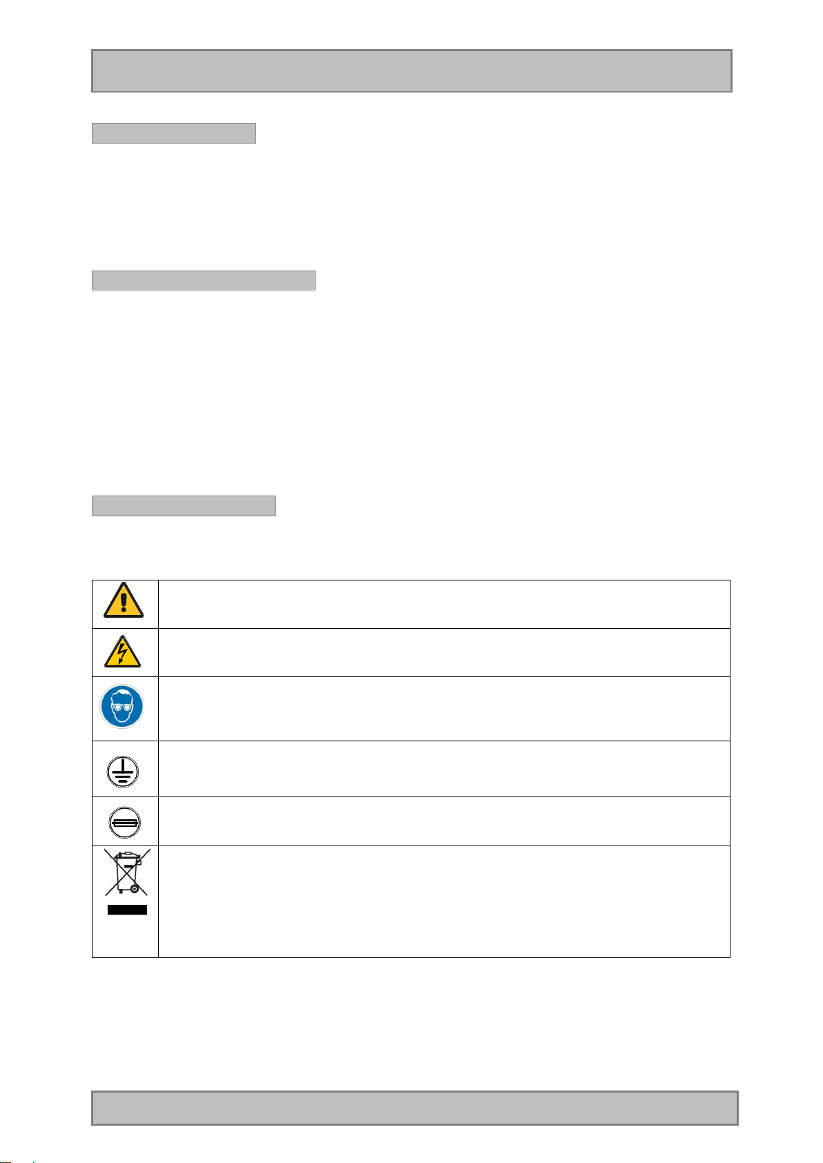
Precautionary labels
Read all labels and tags attached to the instrument.
Personal injury or damage to the instrument could occur if
not observed.
This symbol, if noted on the instrument, references the instruction manual for operation
and/or safety information.
This symbol, when noted on a product enclosure or barrier, indicates that a risk of
electrical shock and/or electrocution exists.
This symbol, when noted on the product, identifies the location of the connection for
This symbol, if noted on the product, indicates the need for protective eye wear.
Protective Earth (ground).
This symbol, when noted on the product, identifies the location of a fuse or current
limiting device.
Electrical equipment marked with this symbol may not be disposed of in European public
disposal systems after 12 August 2005. In conformity with European local and national
regulations (EU Directive 2002/96/EC), European electrical equipment users must now
return old or end-of life equipment to the Producer for disposal at no charge to the user.
Note: For all electrical products (marked or unmarked) which are supplied or produced
Page 6 Manual BÜHLER BU4010ff
by Hach-Lange, please contact the local Hach-Lange sales office for instructions for
proper disposal.
Page 7
Installation
4010
Device designation
Housing Stainless steel with 40 mm insulation,
(material 1.4301/ SS304) / PS / PC (GF10)
Option:
(material 1.4571/ SS316Ti; SS304 EPOXY-coated;
SS316Ti EPOXY-coated)
Thermostatic control Self-contained cooling / heating with 4 settings, no-frost.
Temperature in sample compartment: 4°C (setting range: 0,0-9,9°C)
Control Microprocessor control, foil keyboard, graphical display (128*64 Pixel),
back lit
Data memory Non-volatile data memory: storage of sampling and malfunction data
like sample extractions, bottle changes, messages, external signals
Programming 12 user programs (can be edited freely)
Program start options Immediately, at a certain time, by an external signal
Program stop options End of sampling program after one program run, continuous operation
or x-runs
Pause mode Interruption of program at any time
Overfilling protection Adjustable from 1–999 samples/bottle
Interval setting 1 min. to 99 h 59 min. in steps of 1 minute
Pulse setting 1 to 9999 pulses/sample
Manual sample extraction Possible at any time without interrupting the current program run
Program protection Up to 5 years after voltage loss
Interface Mini-USB, RS422/485, RS 232
Communication Optional: TCP/IP RJ45 WEB board, 4-32GB SD/SDHC memorycard
Optional: Modbus or DP PROFIBUS connection
Languages Multi-language, selectable
Signal inputs • 2x analogue: 0/4-20 mA,
• 8x digital (flow, event, 1x free programmable)
Optional: expansion 4x digital, 3 free programmable and
8x Analogue Inputs 0-20mA / 0-10 V
Pulse-length min. 60 ms u. switch-level 7-24V, max. working
restistance 500 Ohm, signal-length max. 30 m
Signal outputs / status
messages
Sampling method -Vacuum system 20-350 ml, plastic vessel
Single sample volume
accuracy
Suction height Max. 8 m (at 1013 hPa and stagnant medium)
Pumping speed >0,5 m/s at a suction height up to at least 7,8 m (at 1013 hPa); pump
Suction hose PVC, L=7,5 m, ID=12 mm (ID 16 mm at flow-proportional option)
Sampling modes Time-related, flow-dependent, flow-proportional (option), event-related,
Bottle variants Plastic
Overall dimensions (Hxwxd)
Max. 8 digital outputs, 1x collective message
Optional: expansion 8x digital, 5 are free programmable
-Vacuum system 20-500 ml, optional
-Vacuum flow-proportional 5-350 ml, optional
-Bypass system 20-250 ml optional
< 2,8 % at standard vacuum system
capacity can be adjusted electronically.
Max. hose length 30 m
manual sample extraction
1 x 25 L, 1 x 50 L, 2 x 10 L
4 x 6,0 L, 4 x 10 L, 4 x 14 L, 4 x 20 L, 4 x 25 L
12 x 2,9 L, 24 x 1,0 L, 24 x 2,9 L
Glass
12 x 2,0 L, 24 x 1,0 L, 24 x 2 L
1.290 (1.890*)x 690 x 645 mm
for bottle variants: 1x25 L, 1x50 L, 2x10 L, 2x22 L, 4x6 L, 4x10 L,
4x14 L, 12x2 L, 12x2,9 L, 24x1 L
1400 (2015*) x 930 x 850 mm
for bottle variants: 4x20 L, 4x25 L, 24x2,9 L, 24x2 L, 36x1 L
Page 7 Manual BÜHLER BU4010ff
Page 8
Installation
Device designatio
n 4210
Device designation
4410
*) with opened top
Weight 100 kg with composite container; higher weight when using several
bottles and/or glass bottles
Power supply 230 V 50Hz
optional 115 V 50/60Hz
Power requirement Approx. 350 VA (with cooling)
Ambient temperature -20 - +43°C
Sample temperature 0 – 40°C
Standards Device meets ISO 5667 standard
Wetted materials PVC, Silicone, PS, PE, EPDM (optional: glass (Duran50) metering
vessel, sinker weight SS304)
(like 4010, with the following modifications)
Device type Fixed site sampler for sampling of faecal matter
Rinsing water inlet
Rinsing water outlet
Sampling method Vacuum system 20-500 ml
Sampling modes Time-related, flow-dependent, event-related, manual sample extraction
Bottle variants Plastic
Sample distribution Direct distribution with additional position for rinsing water. When using
Overall dimensions 1.290 (1.890*) x 690 x 645 mm
Weight 105 kg with composite container; higher weight when using several
Union nut R 3/4" (max. 2 bar)
Hose connector 25 mm
1 x 25 L, 4 x 14 L, 4 x 20 L
12 x 1 L, 23 x 1,0 L
Glass
12 x 1,0 L, 23 x 1,0 L
the rinsing function, the customer has to make sure that the rinsing
water can drain off freely
for bottle variants: 1x25 L, 4x14 L, 12x1 L
1400 (2015*) x 930 x 850 mm
for bottle variants: 4x20 L, 23x1 L
*) with opened top
bottles and/or glass bottles
(like 4010, with the following modifications)
Device type Self-emptying fixed site sampler for continuous operation without the
need of personnel (monitoring applications)
Emptying/rinsing Bottles are emptied, rinsed and re-filled on the same bottle position.
The rinsing head is installed above the bottle.
Bottle emptying for sample
collection
Hose inlet Hose connection at dosing unit (top)
Hose outlet Hose connection at dosing unit
Rinsing water inlet Union nut R 3/4" (max. 2 bar)
Rinsing water outlet Union nut R 1 1/4". When using the rinsing function, the customer has
Bottle variants Plastic
Overall dimensions (Hxwxd)
According to the device version: manual bottle emptying at 12 and 24-
bottle version or menu-driven emptying at 2 and 4-bottle version
Union nut R 3/4", hose ID 12 mm
Silicone hose 12x2, is only slipped over
to make sure that the rinsing water can drain off freely
2 x 10 L, 4 x 5 L, 4 x 10 L, 24 x 2 L (PPH)
Glass
12 x 1,6 L, 24 x 1,0 L, 24 x 2 L
• 1.290 (1930*) x 690 x 645 mm
Page 8 Manual BÜHLER BU4010ff
Page 9
Installation
Device designation
6010
double
-
housing
Device designation
3010
for bottle variants: 2 x 10 L, 4 x 5 L, 12 x 1,6 L
• 1400 (2175*) x 800 x 850 mm
for bottle variants: 4 x 10 L, 24 x 1 L, 24 x 2 L
*) with opened top
Weight 115 kg with bottle option 2x10 L PE; higher weight when using other
bottle or glass bottle options
(like 4010, with the following modifications)
Device type
Measuring pot inlet Hose nozzle ½“, hose ID 12 mm
Measuring pot outlet Hose nozzle ID 40 mm. The customer has to make sure that the water
Bottle variants Plastic
Overall dimensions (Hxwxd)
Weight Approx. 250 kg with composite container; higher weight when using
Power requirement Approx. 450 VA (with cooling + SC1000 controller), higher requirement
Device type Compact device in plastic housing, especially suitable for high ambient
Suction height Max. 7,5 m (at 1013 hPa and stagnant medium)
Pumping speed >0,5 m/s at suction height up to at least 6 m (at 1013h Pa); pump
Suction hose PVC, L=7,5 m, ID=10 mm (ID 16 mm at flow-proportional option).
Bottle variants Plastic
Sampling method Vacuum system 20-350 ml with plastic metering vessel
Ambient temperature -20°C to + 50°C (tropicalised)
Overall dimensions (Hxwxd)
Weight Approx. 70 kg with composite container, higher weight when using
Fixed site sampler in
in the measuring pot can drain off freely
1 x 25 L, 1 x 50 L, 2 x 10 L
4 x 6,0 L, 4 x 10 L, 4 x 14 L,
12 x 2,9 L, 24 x 1,0 L
Glass
12 x 2,0 L, 24 x 1,0 L
1.690 (2290*) x 1280 x 645 mm
*) with opened top
several bottles and/or glass bottles
when using the optional spiral pump
(like 4010, with the following modifications)
temperatures. Material: PE with 50 mm insulation / Styrosun / PC
(GF10)
capacity can be adjusted electronically
Max. hose length 30 m
1 x 25 L, 4 x 14 L, 12 x 2,9 L, 24 x 1,0 L
Glass
12 x 2,0 L, 24 x 1,0 L
1.100 (1.640*) x 760 x 745 mm
*) with opened top
several bottles and/or glass bottles
(measuring station)
Page 9 Manual BÜHLER BU4010ff
Page 10
Installation
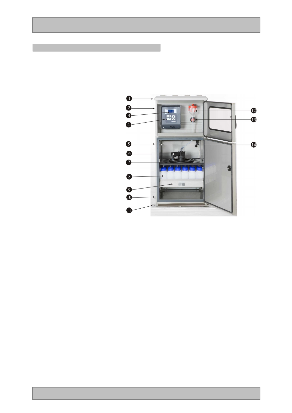
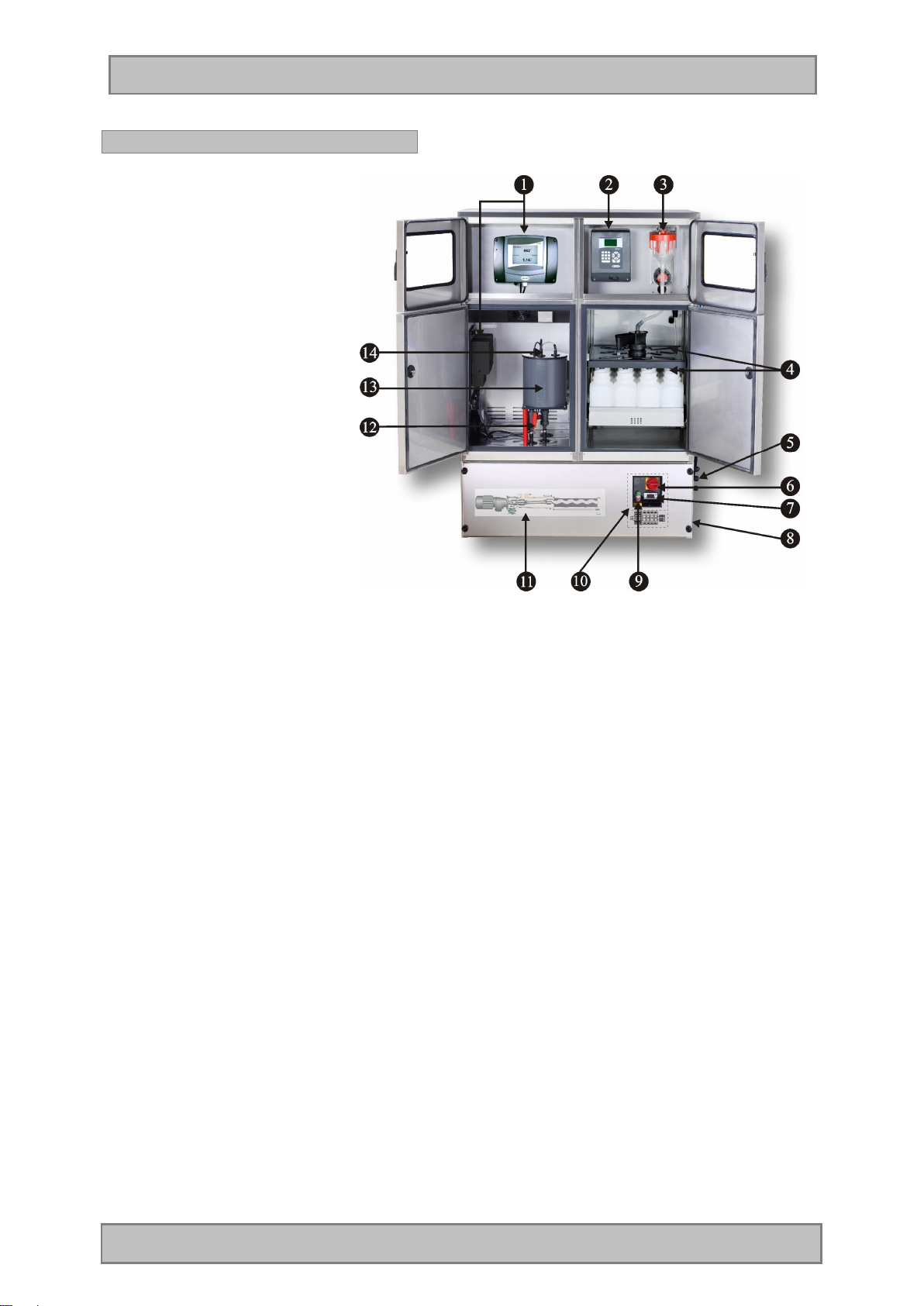
Characteristics: sampler 4010
The device consists of the following component parts:
1. Protective top (can be opened)
2. Upper part of housing
3. Back lit LC-display
4. Keyboard
5. Lower part of housing (cooled
sample compartment)
6. Motor-driven distributor
7. Distributor plate
8. Sample bottles
9. Carrying tray for bottles
10. Fixing bar
11. Fixing bar
12. Dosing unit
13. Pinch valve
14. Type plate
Remark: The illustrated sampler corresponds to a standard version with 12 bottles and
distributor plate.
According to the sampler version, some components such as dosing unit or
distributor/bottles can be different!
Remark: Please read the entire manual before unpacking, installing and operating this device.
Observe all danger and safety regulations. Non-observance can lead to serious
personal injury or to damage to the instrument.
DANGER The workings described in this chapter of the manual must only be carried our by
qualified personnel.
Page 10 Manual BÜHLER BU4010ff
Page 11
Installation
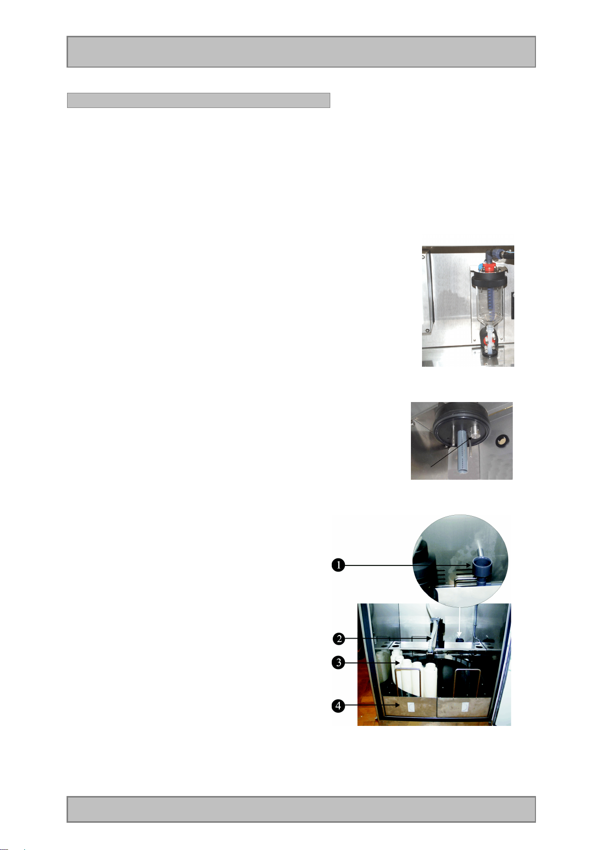
Characteristics: sampler 4210
Compared to the standard samplers, the special sampler for sampling of faecal matter is equipped
with a rinsing unit in the metering vessel and an additional outlet. Furthermore the sample is filled
directly into the bottles. The section from the metering vessel to the distributor outlet is rinsed.
Method of operation: The metering vessel is rinsed automatically after each sample extraction.
To do this, the distributor arm first moves on the discharge position and
then back on the bottle. Thus a sample contamination is avoided.
The picture shows the metering vessel with additional rinsing water
connection.
The rinsing head (arrow) can be seen after having removed the
metering vessel.
The picture shows the distributor unit:
1. Detailed view of discharge position when rinsing.
2. Distributor arm with direct dosing.
3. Sample bottles.
4. Bottle carrying tray.
Page 11 Manual BÜHLER BU4010ff
Page 12
Operation
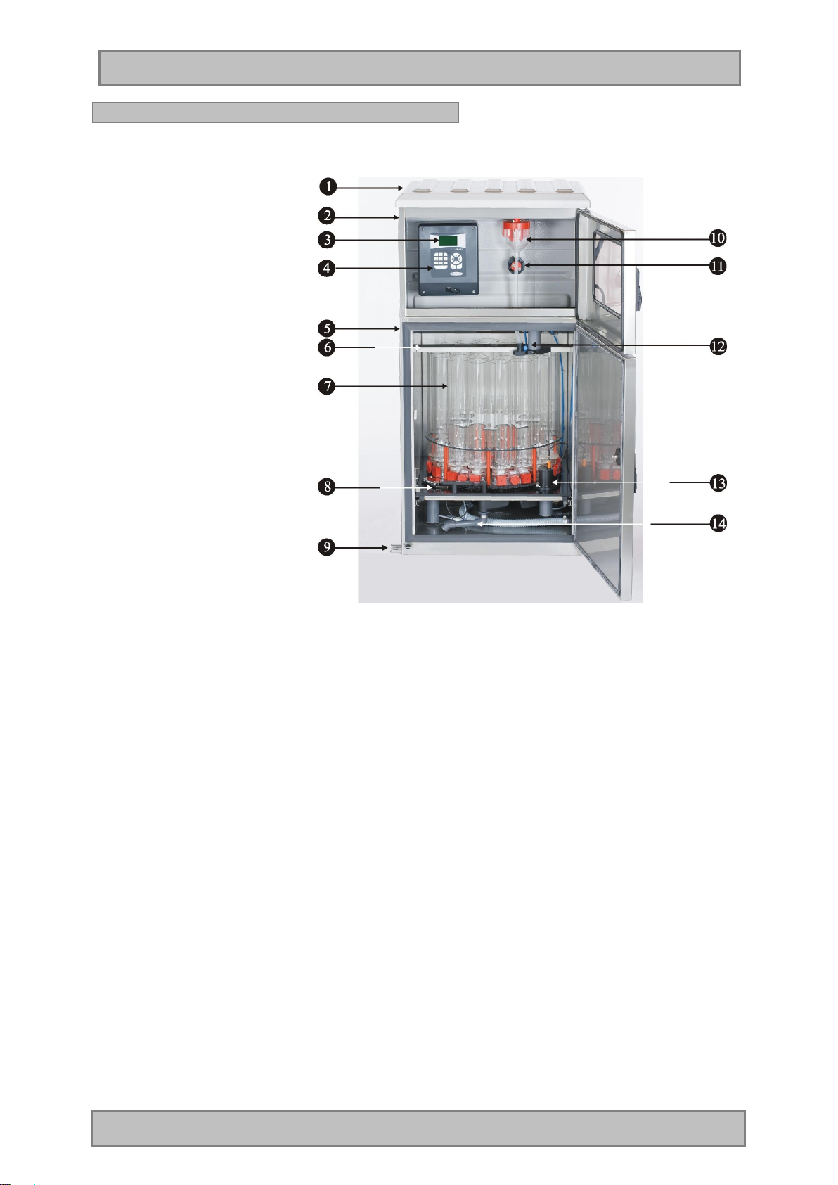
Characteristics: sampler 4410
1. Protective top (can be
opened)
2. Upper part of housing
3. Back lit LC-display
4. Keyboard
5. Lower part of housing
(cooled sample compart ment)
6. Type plate
7. Glass sample bottles
8. Distributor drive
9. Fixing bar
10. Dosing unit
11. Pinch valve
12. Combined dosing and
rinsing head
13. Automatic discharge valve
14. Swivelling sample discharge tube
Remark: The illustrated sampler corresponds to a standard version with 24 bottles.
According to the sampler version, some components such as dosing unit or
distributor/bottles can be different!
Page 12 Manual BÜHLER BU4010ff
Page 13
Operation
Characteristics: sampler 6010
1. Measuring unit with
transducers and display
2. Control
3. Dosing unit
4. Distributor
5. Cable feed through
(opt.: left side)
6. Main switch
7. Display of protection
against dry running
8. Water inlet and outlet
connection (opt.: left side)
9. Pump switch I/O
10. Terminal box
11. Pump (eccentric spiral
pump)
12. Water inlet and outlet of
measuring pot
13. Measuring pot
14. Fixture of electrodes/
measuring probes
Page 13 Manual BÜHLER BU4010ff
Page 14
Operation
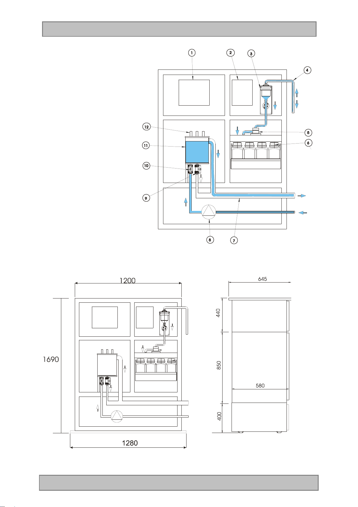
Schematic illustration
Water supply / water drain
1. Measuring transducer with
display
2. Sampler control
3. Dosing system
4. Feed tube of dosing system
5. Distributor
6. Bottles with tray
7. Measuring pot drain pipe
8. Pump (e.g. eccentric spiral
pump)
9. Outlet valve (manual/
automatic) for cleaning of
measuring pot
10. Supply valve for measuring
pot
11. Measuring pot with pressureless
overflow
12. Fixture of electrodes/
measuring probes
Overall dimensions: 1690 x 1280 x 645 mm (hxwxd)
Page 14 Manual BÜHLER BU4010ff
Page 15
Operation
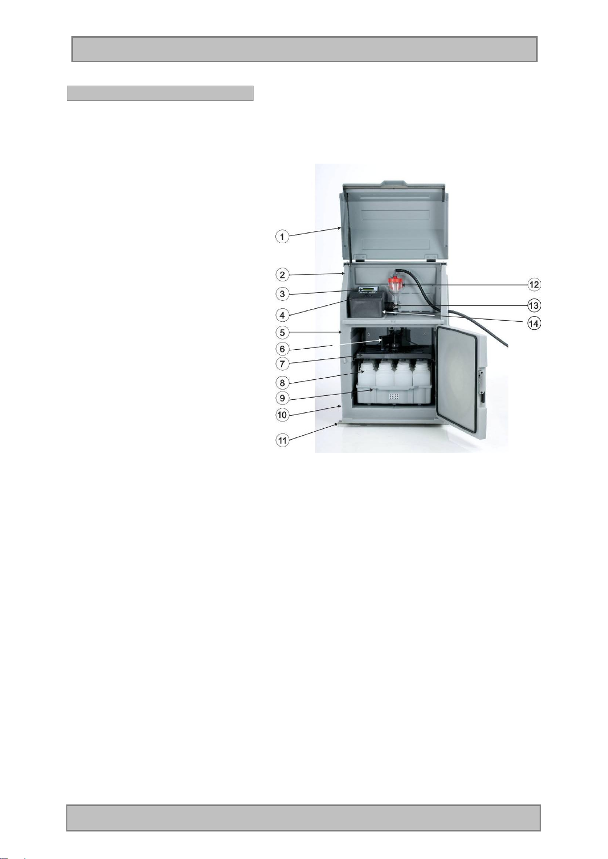
Characteristics: sampler 3010
1. Protective top (can be opened)
2. Upper par t of housing
3. Back-lit LC-display with
keyboard
4. MiniUSB interface
5. Lower part of housing (cooled
compartment)
6. Motor-driven distributor
7. Distributor plate
8. Sample bottles
9. Bottle tray
10. Fixing bar
(illus. with option: mobile version)
11. Fixing bar
12. Dosing unit
13. Pinch valve
14. Type plate
Remark: The illustrated sampler corresponds to a standard version with 12 bottles and
distributor plate.
According to the sampler version, some components such as dosing unit or
distributor/bottles can be different!
Page 15 Manual BÜHLER BU4010ff
Page 16
Operation
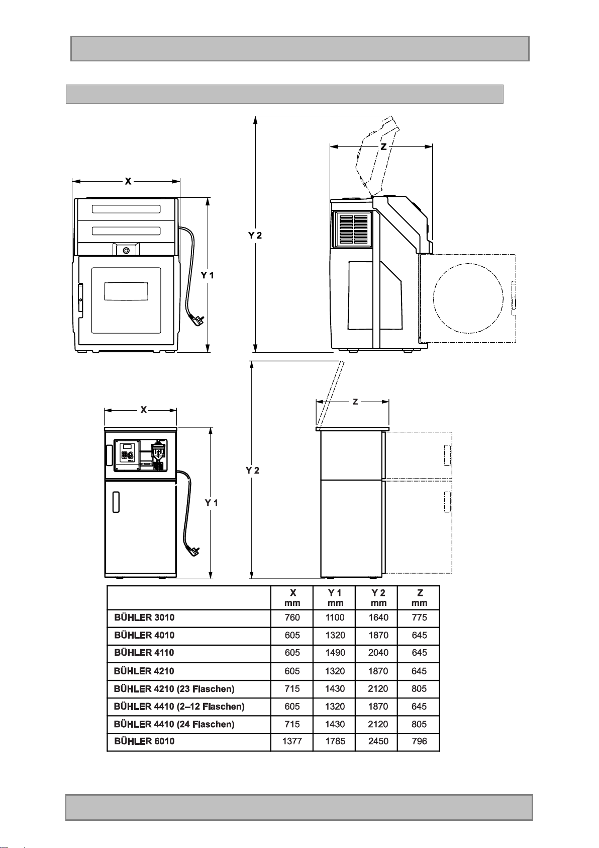
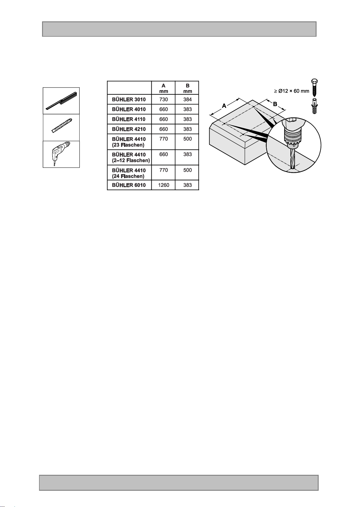
Dimensions of devices
Page 16 Manual BÜHLER BU4010ff
Page 17
Operation
Page 17 Manual BÜHLER BU4010ff
Page 18
Operation
Installing the apparatus
- The workings described in this chapter of the manual must only be carried out by qualified
personnel.
- We recommend to install the apparatus as near as possible to the point of extraction. If installed
outside, the device should be fixed on a solid flat base (e.g. plinth). The fixing bars do already
have the necessary fixing holes.
- If the device is equipped with castors (mobile version), please make sure that the two lock-type
castors are locked during operation.
- For better deaeration / ventilation install the apparatus with a distance of approx. 10 cm to the wall.
- The hose has to be laid with a continuous fall from the apparatus to the point of extraction, without
fail. Lower lying points can lead to deposits in the hose which may freeze up in winter.
- To fix the suction hose, we recommend to use the extraction unit available as accessory.
- Fix the hose in such a way that the suction aperture lies in the direction of flow, so that coarse
matter and fibres cannot be forced into the suction aperture.
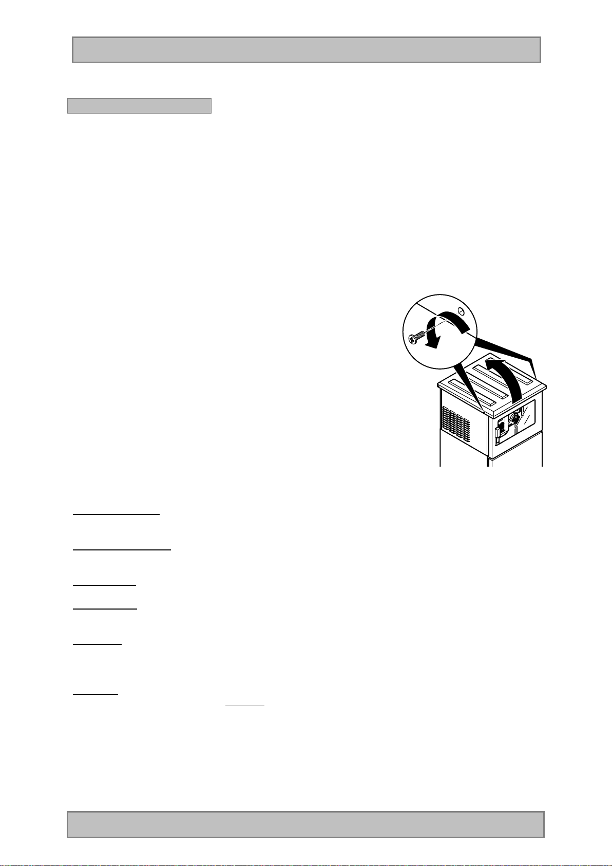
Remark: To open the top cover both front screws (left + right)
have to be removed. Then the top cover can be lifted
up to the point where the retention bars snap-in. To
close the cover again, the two retention bars have to
be lifted slightly.
After having closed the cover, the
two screws (left + right) have to be screwed in again.
Mains connection The device is equipped with a power supply lead.
The connecting data can be found in chapter “Technical Data”.
Connect/disconnect The device is connected/disconnected by means of the mains plug (except
devices with main switch).
Hose routing The apertures for the suction hose are on the left and on the right at the front.
Signal inputs The signal inputs (e.g. for flow meter) are located on the „fold-out“ plate and
can be connected according to the plan of terminal connections shown there.
Messages The relays required for messages (up to 4) can be fixed on the top hat rail. For
details please see the circuit diagram
Remark:
The apparatus must be cleaned regularly in accordance with the degree of contamination present. In
view of the quality of samples, we recommend to clean thoroughly especially the wetted parts like
dosing unit, electrodes, distributor, bottles and inlet hose. Failure to do so could result in damage or
destruction to the equipment, device that are not covered by warranty.
Page 18 Manual BÜHLER BU4010ff
Page 19
Operation
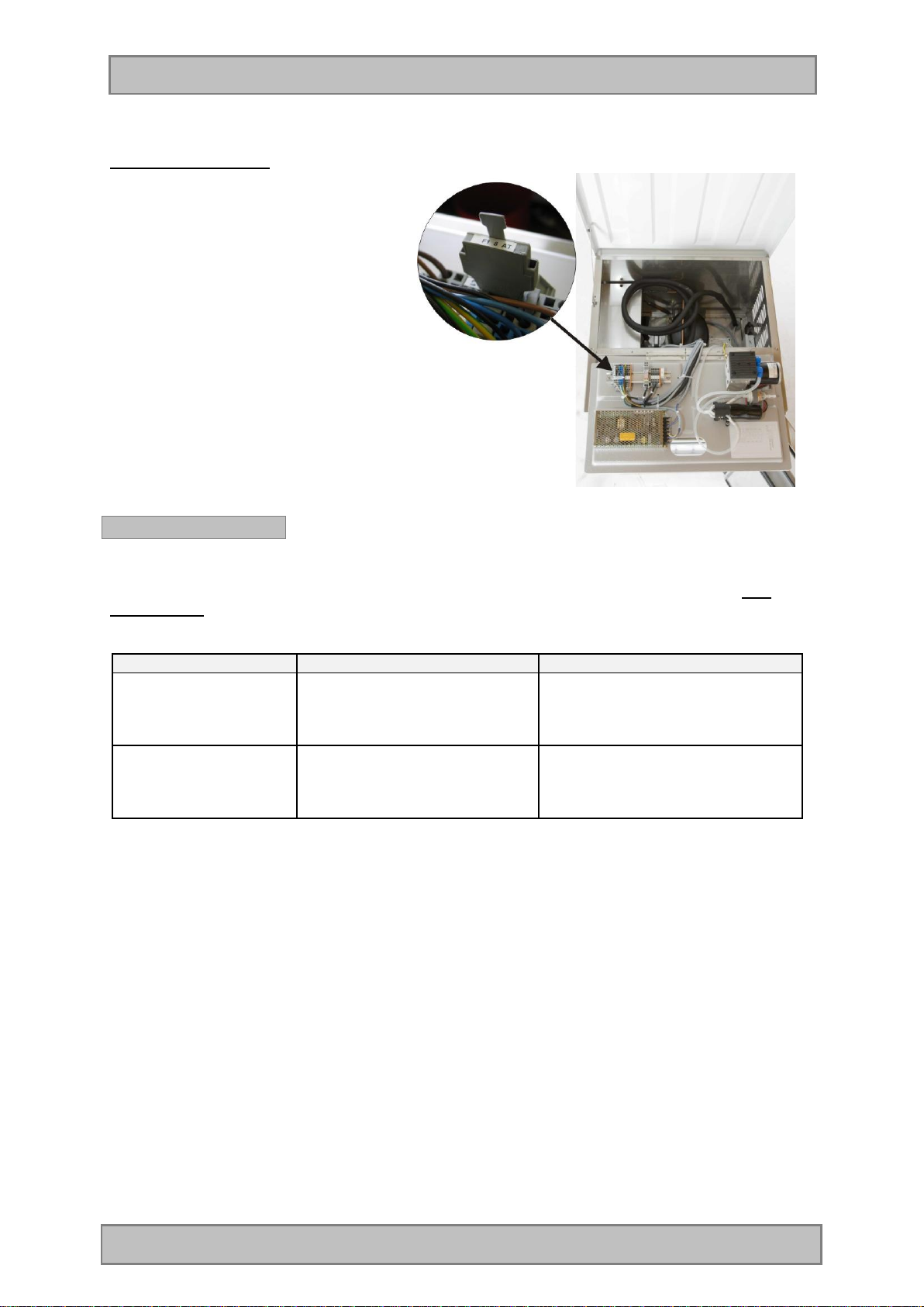
Replacement of fuses
1. Main fuse of device
(is installed on fold-out plate)
Fine-wire fuse 230V/T8A 5x20
To replace the fuse, pull out fuse holder,
open the cover and remove the fuse.
2. Fuse protection of CPU board
by an automatic fuse. The fuse is
reactivated by disconnecting the device
from the mains.
Troubleshooting
If a fault develops in your sampler, we can only provide prompt assistance if you give us the type and
serial number of the apparatus concerned. You will find these data on the type plate.
The more precise your description of the fault is, the better our fault diagnosis will be.
Symptom Possible cause Action
Sampler does not
function at all
Cooling system does
not function
- Mains connection
- Fuse defective
- Power supply
- Cooling system leaking
-Check mains cable
-Check all fuses and replace them
if necessary
-Check mains connection of
cooling machine
-Contact service department
Page 19 Manual BÜHLER BU4010ff
Page 20

Operation
Connections
Terminal assignment – input signals
Remark: Terminals K2 to K4 are optional depending on the device version.
BL3010
Page 20 Manual BÜHLER BU4010ff
Page 21

Operation
Sampling modes
The following sampling modes can be programmed:
Sampling mode Description Example
Time-
proportional
Flow-dependent
- digital
Flow-dependent
- analogue
In this sampling mode, the
single sample extractions as
well as the bottle change are
effected in fixed time intervals.
In this sampling mode the
sample extraction is triggered
by flow pulses. The bottle
change is effected in fixed time
intervals or after a certain
number of sample extractions.
In this sampling mode samples
are extracted according to the
analogue flow signal (0-20 mA
or 4-20 mA). The sample
extraction is started when the
programmed flow is reached.
Thus the interval between the
sample extractions varies
according to the flow signal.
The bottle change is effected in
fixed time intervals or after a
certain number of sample
extractions.
Values to program:
sampling interval
e.g. 00:05 hh:mm
Bottle filling time
e.g. 02:00 hh:mm
Values to program:
pulse divider
e.g. 100
(that means that a sample is
extracted after each 100th
pulse).
Bottle filling time
e.g. 02:00 hh:mm
or
bottle change after X sample
extractions e.g. 100
Values to program:
Flow per sample extraction
e.g. 1 m³
Bottle filling time
e.g. 02:00 hh:mm
or
bottle change after X sample
extractions e.g. 100
Flowproportional
Page 21 Manual BÜHLER BU4010ff
Samples are not extracted with
a fixed volume but within a
fixed time interval (e.g. every
10 minutes).For this kind of
sampling, the variable
automatic dosing system
(available as option) is
required. This system is only
working with an analogue flow
signal!
The sample volume adapts
•Analogue signal (4-20 mA or
optional 0-20 mA)
•The max. sample volume at
20 mA is fixed to 200 ml.
At an analogue signal of e.g.
10 mA, a 100 ml sample would
be extracted accordingly.
Sampling is effected in a fixed
time interval of e.g. 10
minutes.
Thus the sample extraction is
Page 22

Operation
Eventproportional
itself automatically
proportionally to the flow. This
is achieved by proportionally
scaling the mA signal and the
maximum sample volume. That
means, the sample volume is
automatically adjusted to the
mA
signal.
In this sampling mode the
sample extraction is depending
on an external event signal
(potential-free make contact).
The sample is only extracted as
long as the signal is present.
The sampling interval as well
as the bottle change are
programmed. The bottle is
changed at each new event
signal.
If an event is longer than the
programmed bottle filling time,
two or more bottles will be filled
for this event depending on the
programmed bottle filling time.
always proportional to the flow,
that means:
high flow = big sample
volume
low flow = small sample
volume.
Values to program:
Sampling interval
e.g. 00:05 hh:mm
Bottle filling time
e.g. 02:00 hh:mm
Page 22 Manual BÜHLER BU4010ff
Page 23

Operation
Vacuum sampling system
Metering vessel -structure-
1. Hose connector
2. Flange
3. Screw cap
4. Electrodes
5. Volume control tube
6. Metering vessel
7. Silicone discharge tube
8. Motor-driven pinch-valve
9. Air connection
Cleaning:
- Glass metering vessel: unscrew the screw cap (3) and remove the flange. Now, the metering
vessel together with the silicone discharge tube (7) can be detached.
- Plastic metering vessel: Turn the plastic metering vessel anticlockwise (bayonet fitting) and
remove.
Adjustment of sample shot volume at samplers with glass metering vessel:
To adjust the desired sample volume, loosen the knurled screw and displace the volume control tube
vertically.
Adjustment of sample shot volume at samplers with plastic metering vessel:
The sampler is always delivered with the volume control tube in full length.
To adjust the sample shot volume, the volume control tube (5) has to be cut
to length.
Procedure
1. There is a graduation in millilitres on the volume control tube.
2. Remove the metering vessel (6).
3. Cut the volume control tube to the desired length with scissors or a knife.
4. Reinstall the metering vessel (6) and tighten.
5. Check the sample volume by starting a manual sample extraction.
6. Now the device is ready for operation.
Remark: If you need to work with different sample volumes, you can cut to
size several tube pieces. As the volume control tube (5) is only
slipped on the hose connector (1), it is very easy to change the tube.
Page 23 Manual BÜHLER BU4010ff
Page 24

Operation
Operation principle:
1. Inoperative
position
Replacement of the silicone discharge hose
The silicone hose (BM69301) is only pushed over the lip of the metering vessel. A hose clamp is not
required. Humidify the hose a little bit, fix it at one point and push it over the lip.
Remark:
Do only use original spare parts from the manufacturer. The use of a wrong hose type can lead to
malfunctions at the system or may even damage the pinch valve!
Remark:
Conductivity of the sample medium
There are two conductive level electrodes in the metering vessel. Their sensitivity can be adjusted in
the service menu. In the factory the electrodes are adjusted to tap water (this adjustment does not
have to be changed under normal operating conditions). Minimum conductivity 50 μS/cm.
Please note that a wrong adjustment can lead to a flooding of the pneumatic system and to the
damage of component parts.
The sampler is not suitable for extraction of distilled water due to low conductivity.
Conductivity at 25°C
Rain water 50 μS/cm
Drinking water 500 μS/cm
Waste water 5000 μS/cm (5 mS/cm)
Seawater 50000 μS/cm (50 mS/cm)
ATTENTION:
Wrong operating conditions can lead to malfunctions or may even damage the apparatus. No liability
or claims under guarantee will be accepted in respect of any damage arising from the non-observance
of these operating instructions.
2. Pinch-valve
closes
3. Metering
vessel is filled
up to the
electrodes
4. Dosing system
is aerated
5. Pinch
valve
opens and
sample
drains off
in bottle
Page 24 Manual BÜHLER BU4010ff
Page 25

Operation
Troubleshooting – vacuum sampling system
If a fault develops in your sampler, we can only provide prompt assistance if you give us the type and
serial number of the apparatus concerned. You will find these data on the type plate.
The more precise your description of the fault is, the better our fault diagnosis will be.
Symptom Possible cause Action
Electrodes do not react,
system flooded
Sampler does not extract
samples
No pressure / vacuum at
pump
Adjustment of conductivity too
low. Distilled water has been
used as sample medium.
No contact to electrodes Check cable connection
System is leaking Check whether all hoses and
Pump/diaphragm defective Check pressure/vacuum of
Metering vessel not tight, no
vacuum
Filling level electrodes bridged Clean electrodes
Valve system/pinch valve does
not function correctly
Defective diaphragm Renew diaphragm
Hoses are squeezed Check hoses
Contact service department
connections are tight
pump
Check whether metering vessel
is tight (screw cap)
Check valve system/pinch valve
or contact service department
Page 25 Manual BÜHLER BU4010ff
Page 26

Operation
Flow-proportional sampling system
The characteristic features of the flow-proportional sampling are:
• fixed sampling interval (e. g. every 10 min) with
• variable sample volume (related to the mA-signal (flow))
At the variable dosing system, the sample volume is automatically changed according to the analogue
flow signal.
Example: - the selected range is 4 to 20 mA (option 0 – 20 mA)
- the maximum sample volume at 20 mA is fixed to 200 ml.
That means at an analogue signal of e.g. 10 mA, a 100 ml sample would
be extracted. Thus the sample extraction is always proportional to the flow.
This sampling mode supplies very good, representative results as even if flow is very low (e.g.
discharges at night) a sample extraction is still carried out in fixed time intervals.
For comparison a short description of the flow-dependent sampling mode:
The characteristic features of the flow-dependent sample extraction are:
• variable sampling interval (according to the mA-signal (flow)) with
• fixed sample volume (e.g. 100 ml)
In the flow-dependent sampling mode, a sample is e.g. always extracted after 10 m³, that means the
signal of the flow meter is totalized.
In case of very low flow quantities (e.g. discharges at night) it is possible that e.g. 2-3 hours pass until
the set 10 m³ are reached again and a sample is extracted.
Remark: That means if there is an accident (e.g. discharge of chemicals) during this period, there
will be no sample. However, a sample would have been very important for an analysis and
the taking of countermeasures.
Flow-proportional sampling system - structure
Structure:
1. Electrodes 2
2. Measuring tube
3. Electrodes 1
4. Connection for aeration
5. Dosingvessel
6. Pinsch Valve
7. Cleaning cap of gas drap
8. Inlet connection
Page 26 Manual BÜHLER BU4010ff
Page 27

Operation
Function of the VAR Flow-proportional sampling system
· Before the system can be used, it must be calibrated. In the automatic calibration cycles (5
cycles), the respective volumes must entered.
· At the flow-proportional (variable) sampling system the sample volume is directly entered in ml by
means of the keys at the control when editing a sampling program.
· After the program start the pinch valve is closed.
· A pressure (air produced by the diaphragm pump) is applied to the metering vessel via the air
connection. Thus the hose is purged.
· Now, the valve system switches to vacuum and the depression generated by the diaphragm pump
withdraws the air from the metering vessel. A vacuum is generated and leads to the drawing-off of
sample medium at the connected hose.
· The medium is sucked into the Dosingvessel over the Measuring tube (2).
· during inlet, the sample volume already will be measured in the measuring tube(2) and only the
requested volume remains in the vessel.
· After measuring is done, the system is ventilated by opening the air inlet (4) so that the water in
the suction hose can flow back to the extraction point.
· After a pre-programmed aeration time, the pinch valve (6) opens in two steps and the sample is
filled into a container.
Cleaning:
To clean the metering vessel (5), open the screw cap (glass) or turns to the left (plastic, bayonet
shutter), pull the silicone discharge hose to the front and remove the metering vessel.
The measuring tube (2) can be cleaned with a bottle brush BM60560 .
Page 27 Manual BÜHLER BU4010ff
Page 28

Operation
Troubleshooting – flow-proportional sampling system
If a fault develops in your sampler, we can only provide prompt assistance if you give us the type and
serial number of the apparatus concerned. You will find these data on the type plate.
The more precise your description of the fault is, the better our fault diagnosis will be.
Symptom Possible cause Action
Level electrodes do not react,
system is flooded
Sampler does not extract
samples
Pump does not produce
pressure/vacuum
Adjustment of conductivity is
too low. Distilled water is used
as sample medium
No contact to electrodes Check cable connections
System is leaking Check whether all hoses and
Pump/diaphragm defective Check pressure/vacuum of
Metering vessel not tight, no
vacuum
Level electrodes are bridged Clean electrodes
Valve system/pinch valve does
not work correctly
Diaphragm defective Replace diaphragm
Hoses are kinked Check hoses
Contact service department
connections are tight
pump
Check whether metering vessel
is tight (union nut)
Check valve system/pinch valve
or contact service dept.
Inaccurate sample volume
Page 28 Manual BÜHLER BU4010ff
System has been initialized or
hardware has been changed
Calibrate
Page 29

Operation
Bypass sampling system
Bypass metering vessel
This sampling method is suitable for use in bypass systems with flow-rates from 3 – 20 L/min.
- Patented motor-driven pinch valve which squeezes the dosing hose or the flow-through hose
below the metering vessel.
- No sensor, thus almost no wear.
- Front opening for ease of metering vessel cleaning
- The sample volume can be adjusted between 20 ml and 250 ml by displacing the filling tube
Metering vessel – structure -
1. Sample inlet
2. Hose connection for overflowing water
3. Flange
4. Screw cap
5. Filling level electrodes
6. Metering vessel
7. Adjustable tube – sample volume
8. Screw connection
9. Pinch valve 1 (sample outlet to distributor/bottles)
10. Silicone discharge tube
11. Pinch valve 2 (dosing)
12. Outlet hose
Method of operation
The desired volume can be adjusted between approx. 20 ml and 250 ml by means of the adjustable
tube. To adjust the desired sample volume, loosen the screw connection and displace the filling tube
upwards or downwards.
1. Continous flow
Inoperative Position
4. Pinch valve 2 is opened.
Water drains off up to the
level of the dosing tube.
2. Pinch valves 1+2 are closed 3. Water is filled up to the
electrodes
5. Pinch valve 1 is opened
and the sample is filled
into the bottle.
6. Inoperative Position
Page 29 Manual BÜHLER BU4010ff
Page 30

Operation
REMARK: The pinch valve (9) is in inoperative position always closed and will be opened 1x per
hour to avoid sticking of the silicon tube.
Replacement of dosing hose
The silicone hose (BM69301) is only pushed over the lip of the metering vessel. A hose clamp is not
required. Humidify the hose a little bit, fix it at one point and push it over the lip.
Remark: Conductivity of the sample medium
There are two conductive level electrodes in the metering vessel. Their sensitivity can
be adjusted progressively in the service menu. The factory adjusts the electrodes to
tap water (this adjustment does not have to be changed under normal operating
conditions).
Please note that a wrong adjustment can lead to a flooding of the pneumatic system and to the
damage of component parts.
ATTENTION: Wrong operating conditions can lead to malfunctions or may even damage the
apparatus. No liability or claims under guarantee will be accepted in respect of any
damage arising from the non-observance of these operating instructions.
Troubleshooting – bypass sampling system
If a fault develops in your sampler, we can only provide prompt assistance if you give us the type and
serial number of the apparatus concerned. You will find these data on the type plate.
The more precise your description of the fault is, the better our fault diagnosis will be.
Symptom Possible cause Action
Level electrodes do not
react, system is flooded
Sampler does not
extract samples
Metering vessel
overflowing (backflow)
-Adjustment of conductivity is too
low
-Failure on the power board
-Defective cable connection
-Wrong programming
-System is leaking
-No flow
-Inlet hose clogged
-Level electrodes bridged
-Wrong setting of parameters in
the service menu
-Outlet hose is clogged or
squeezed
-Pinch valve does not open
completely
-Check adjustment in service
menu
-Exchange power board
-Check cable connection
-Check programming
-Check whether the silicone
hoses are tight
-Check whether there is water
-Remove clogging
-Clean the electrodes
-Check entered values and, if
necessary, reset them to factoryset values by reinitialization
-Remove clogging
-Adjust position of pinch valve
Page 30 Manual BÜHLER BU4010ff
Page 31

Operation
Sample distribution at Bühler 4010/3010//6010
Ÿ Rotating distributor
- Motor-driven rotating distributor with encoder (pulse generator) which ensures:
- an exact sample discharge position as well as
- an automatic bottle position identification by means of a forked light barrier.
Remark: For reasons of operating safety, the distributor first always runs over position 1 again
when changing to the next bottle. Thus a correc t positioning even after a malfunction
(voltage loss) is always guaranteed.
Remark 2: When there are no pulses, the output is switched off and thus neither the motor
nor the gear will be damaged if the distributor is blocked.
ATTENTION: The distributor is driven by a geared motor. The distributor must under no
circumstances be turned by hand! In case of non-observance, the gear will be
damaged!
Page 31 Manual BÜHLER BU4010ff
Page 32

Operation
Troubleshooting – distributor 4010/3010//6010
If a fault develops in your sampler, we can only provide prompt assistance if you give us the type and
serial number of the apparatus concerned. You will find these data on the type plate.
The more precise your description of the fault is, the better our fault diagnosis will be.
Symptom Possible cause Action Chapter
No function
Program cannot be
started
Distributor is
continuously turning
Wrong positioning of
distributor
Connections
Water penetrated in distributor
drive
Wrong distributor has been
entered
Forked light barrier defective
Pulse generator defective
Interfering pulses.
Pulse generator does not
function correctly
Check connections
Dismantle distributor
head and check for
water penetration.
Contact service
department
Correct entry
Contact service
department, return
defective part if
necessary
Contact service
department
Distributor
Programmin
g
Distributor
Distributor
Sample distribution at Bühler 4210
The picture shows the distributor unit:
1. Detailed view of discharge position when rinsing
2. Distributor arm with direct dosing
3. Sample bottles
4. Bottle carrying tray
Page 32 Manual BÜHLER BU4010ff
Page 33

Operation
Sample distribution at Bühler 4410 – variants: 12 / 24 bottles
Distributor
The distributor system is available in two variants:
- with 12 glass bottles, each 1,6 L
- with 24 glass bottles, each 2 L.
General view – complete distributor system with bottles:
1. 1,6 L or 2 L Duran50 glass bottle.
2. Drive unit with releasing mechanism, that means if the distributor is blocked, the drive unit is released.
Thus severe damage to the distributor is avoided.
3. Distributor drive unit.
4. Swivelling outlet tube for the manual emptying of the bottle.
5. Combined dosing/rinsing head. On this position the glass bottles are automatically emptied, rinsed
and filled again. For rinsing, the device has to be connected to a fresh water pipe. The emptying and
rinsing intervals can be set in the service menu.
6. Emptying mechanism. There is a silicone hose at the bottle outlet which is closed if non-operated by
means of a spring mechanism. To empty the bottle, the bottle outlet valve is opened and closed again
after rinsing by means of an eccentric unit.
7. Closing cylinder of bottle.
8. Lever to empty the bottle manually. To actuate the closing cylinder, the lever has to be turned to the
right. Now, the sample can be filled into a separate bottle.
9. Discharge tube for not needed samples and rinsing water with external hose connection to return this
water to the sewer.
Page 33 Manual BÜHLER BU4010ff
Page 34

Operation
Take out, empty or put in a bottle
To empty a bottle, to take it out for cleaning or to put it in again, the desired bottle can be moved to the
front position by means of the menu „Manual Mode“. This is also possible during a running program by
means of the pause mode. The active program does not have to be interrupted and continues to run
according to the programmed cycle, however, in the background. Detailed information can be found in
the chapter „Programming“.
Detailed view – distributor drive
Detailed view – dosing/rinsing head
Page 34 Manual BÜHLER BU4010ff
Page 35

Operation
Sample distribution at Bühler 4410 – variants: 2 / 4 bottles
1. Distributor
2. Rinsing water connection
3. Container
4. Locking device for telescopic drawer
5. Telescopic drawer
6. Discharge trough
1. Description
The motor-driven distributor unit consists of a distributor tie-bar, a drive unit with motor,
a light barrier and encoder as well as a distributor head with outlet tube.
There are 2 x 10 L PE containers (or 4 x 5 L PE containers) and each container is equipped with
a discharge valve at the bottom. In addition there is a rinsing valve for each bottle at the bottom
of the inner compartment.
2. Operating elements
The red screw cap of the distributor head can be unscrewed for cleaning.
Attention: Never turn the distributor by hand (geared motor)!
3. Method of operation
- The device is typically programmed in such a way that each container is filled for a period of 24
hours. Thus, a sample of the last 24 hours is available at any time.
- At each bottle change, the distributor passes a light barrier at position 1 to synchronize.
- After having passed the light barrier, the encoder pulses of the motor are counted to position the
outlet tube on bottle 2.
- After each program-related bottle change, the new bottle is automatically emptied and rinsed.
- To do this, the distributor first moves on the respective bottle.
- Thereafter the discharge valve at the bottom of the container is opened.
- After expiration of the emptying time (adjustable), the respective rinsing valve is opened (rinsing
time is adjustable, too) and the container is rinsed.
- After rinsing, the discharge valve closes and the device is ready for sampling again.
Page 35 Manual BÜHLER BU4010ff
Page 36

Operation
Troubleshooting – distributor Bühler 4410
If a fault develops in your sampler, we can only provide prompt assistance if you give us the type and
serial number of the apparatus concerned. You will find these data on the type plate.
The more precise your description of the fault is, the better our fault diagnosis will be.
Symptom Possible cause Action Chapter
No function
Program cannot be
started
Wrong positioning of
distributor
Connections
Wrong distributor has been
entered
Interfering pulses.
Pulse generator does not
function correctly
Check connections Distributor
Correct entry
Contact service
department
Programming
Distributor
Page 36 Manual BÜHLER BU4010ff
Page 37

Operation
Programming
The menu structure is similar to a directory tree and is split up in
main menus and submenus.
Assignment and function of keys
The apparatus is interactively programmed by the user.
Function of keys:
Display of help texts. To activate the help
text when selecting a new display, first
Arrow key
press the arrow key pointing to the left.
Move from one to the next menu Arrow keys
Select the desired menu Enter key
Move within the menu Arrow keys
Selection within the menu or scrolling
within the data memory or bottle memory
Confirm the choice (is automatically
marked with a )
Arrow keys
Enter key
Entry/change of values Arrow keys
Confirmation of entered values Enter key
Return to higher menu level Back key
Initialization (reset) display
Back key +
Enter
Terminate sleep mode Back key
RESET / reset to factory settings Back key
Press both keys at the
same time
Press for at least
5 sec.
Keep pressed
when switching on
Page 37 Manual BÜHLER BU4010ff
Page 38

Operation
Navigation
The sampler can be operated by means of the control
unit. With the ARROW KEYS, the ENTER KEY and the
BACK KEY you can move from one screen to another.
An arrow on the display shows that there are further
selection possibilities (see illustration).
Example:
1. Press the “DOWN” arrow key two times to select the line DATA MEMORY.
2. Now press the ENTER KEY to display the data memory or to choose another
selection possibility.
Remark: The arrow pointing downward on the right side (bottom) of the display
indicates that there are further selection possibilities.
Menu variants:
The top line indicates that you can navigate to the right
or to the left by pressing the arrow keys.
The bottom line indicates with which key the action is
executed or terminated.
Here you can set a parameter. The top line shows
which value is to be set. The bottom line indicates the
possible range of values. The entry is possible directly
by means of the number keys or the digit is selected
with the right / left arrow keys and changed with the up
/ down arrow keys. The selected digit is displayed
inversely (cursor). Confirm the entry by pressing the
ENT key or abort it by pressing the BACK key (in this
case the initial value is not changed).
The arrows show that a digit can be changed.
Page 38 Manual BÜHLER BU4010ff
Page 39

Operation
Settings with selection menu
The cursor is positioned on the current selection line
(inversely) and can be moved up or down.
The arrow on the right side of the window indicates
that there are further entries which can be displayed
by scrolling up or down.
Depending on the menu, the display will show
in which direction you can scroll.
Definition of individual menu points
In the selection menus, additional program settings
are displayed. All the settings which have been
activated by pressing the ENTER key are marked
with a .
Page 39 Manual BÜHLER BU4010ff
Page 40

Operation
FUNTION
PROGRAMS
MANUAL SAMPLE
DATA MEMORY
DIAGNOSTICS/TEST
MAIN MENU STRUCTURE
The following list shows the main menu level with the menu points of the
submenus:
DISPLAY
DISPLAY
STATUS/STOP • INFO
• PAUSE
• STOP
START • IMMEDIATELY
• DATE/TIME
• WEEKDAY/TIME
CHANGE Time,Flow, Event
INTO CURRENT BOTTLE
EXTRACTION
INTO BOTTLE X
INFO MEMORY SET FILTER
BOTTLE PROTOCOL
COMPONENT TEST • DIAPHRAGM PUMP
• PINCH VALVE
• VALVE SYSTEM
• DISTRIBUTOR
• DIGITAL OUTPUTS
DIGITAL INPUTS FLOW DIGITAL 0 EVENT 0
DI3 DI4 DI5
DI6 DI7 DI8
ANALOG INPUTS ANALOGUE 1:
ANALOGUE 2:
ELECTRODES 1:
ELECTRODES 2:
PT 1000 SENSOR
VOLTAGE.:
VERSION INFO
Page 40 Manual BÜHLER BU4010ff
Page 41

Operation
SETTINGS
DATE/TIME
SYSTEM SETTINGS • LANGUAGE
SLEEP MODE
(Only portable sampler)
• DISTRIBUTOR
• MAX. SUCTION TIME
• PRE PURGE
• POST PURGE
• AERATION TIME
• PUMP POWER
• ANALOGUE SIGNAL
• DISPLAY
• PAUSE DURATION
• PROG. INPUT
• OUTPUTSIGNAL
• DATE/TIME
• WAKEUP WITH 5s ESC
• NO SLEEP MODE
PASSWORD • CHANGE PASSWORD
• CHANGE SETTINGS
• CHANGE PROGRAMS
SERVICE MENU Setting of base parameters
(to be done by a service
technician)
Password protected.
Page 41 Manual BÜHLER BU4010ff
Page 42

Operation
PROGRAMS
MANUAL SAMPLE
DATA MEMORY
Description of the menus
DISPLAY
STATUS/STOP
START
CHANGE PROGRAM No. [xx]
EXTRACTION
IN CURRENT BOTTLE
IN BOTTLE X
INFO MEMORY
BOTTLE MEMORY
DISPLAY
• INFO
• PAUSE
• STOP
• IMMEDIATELY
• DATE/TIME
• WEEKDAY/TIME
EXPLANATION / FUNCTION
Display of program details
Interruption of the running
program (max. 120 min.)
Stop /abort the program
Program start can be:
• immediately
• with date/time (dd:mm:yyyy
hh:mm)
• with weekday/time (day; hh:mm)
Change the program parameters
like mode of operation (time, flow,
event…), interval etc.
Selectable Modes:
• TIME
• FLOW DIGITAL
• FLOW ANALOGUE
• EVENT TIME
• EVENT DIGITAL
• EVENT ANALOGUE
Sample extraction into current
bottle
Sample extraction into selectable
bottle X
Data can be displayed with filter
Display of data of the single
bottles
Page 42 Manual BÜHLER BU4010ff
Page 43

Operation
DIAGNOSIS/TEST
SETTINGS
• DIAPHRAGM PUMP
• PINCH VALVE
COMPONENT TEST
• VALVE SYSTEM
• DISTRIBUTOR
• DIGITAL OUTPUTS
OUTPUTS TEMPCARD
DIGITAL INPUTS
ANALOG INPUTS
DISPLAY OF VERSION
DATE/TIME Setting of date / time
• LANGUAGE
• DISTRIBUTOR
• MAX. SUCTION TIME
SYSTEM SETTINGS
• PRE PURGE
• POST PURGE
• AERATION TIME
Functional check of the
components
Displays status of:
- Lower heating (OFF / ON)
- Cooling (OFF / ON)
- Upper heating (OFF / ON)
Display of
(DI=Digital Input):
- Flow digital Event (digital)
DI3 DI4 DI5
DI6 DI7 DI8
Display of:
- ANALOGUE 1
- ANALOGUE 2
- Electrodes 1
- Electrodes 2
- PT1000 temperature sensor
(option)
- Operating voltage
Display of the firmware version
Setting of device-specific
parameters
1.PRE Purge=purging of suction hose
before sampling
2. Post purge= active purging of
dosing vessel to adjust dosing volume
Page 43 Manual BÜHLER BU4010ff
Page 44

Operation
SLEEP MODE
PASSWORD
SERVICE
• PUMP POWER
• ANALOGUE SIGNAL
• DISPLAY
• PAUSE DURATION
• PROGR. INPUT
• OUTPUT SIGNAL
The program can be interrupted
for a period of 10-120 minutes
Inputsignal to start e.g. a program
Only active if the add-on board is
connected
• DATE/TIME
• WAKEUP WITH 5s ESC
ONLY FOR PORTABLE
SAMPLER
• NO SLEEP MODE
• CHANGE PASSWORD
• CHANGE SETTINGS
Setting / activation of the
password
• CHANGE PROGRAMS
Setting of base parameters (to be
done by a service technician)
(Password protected)
Page 44 Manual BÜHLER BU4010ff
Page 45

Operation
Examples of programs
Programming of a time-proportional sampling
program
Select PROGRAMS in the main menu
Select CHANGE
Select PROGRAM NO. 1 (out of 12).
Programs No. 2-12 can be selected by pressing the left
or right arrow key.
Press ENTER to edit the program.
Select the sampling mode TIME
(Sampling is effected in fixed time intervals)
Set the sampling interval
(time interval between the single sample extractions)
Page 45 Manual BÜHLER BU4010ff
Page 46

Operation
Set the BOTTLE FILL TIME
(here: each bottle is filled for 1 hour).
Terminate programming.
Now, the program can be started directly.
If selected "MORE SETTINGS ", the additional settings
are available:
- PROGRAMMING OK
(Set of selection and back to the START Menue)
- SERIAL SAMPLES
(samples/extraction)
means that each requested extraction consists of x-samples. This is useful
for a larger sample volume.
- BOTTLE SELECTION
(first Bottle / last Bottle)
The first and the last bottle can be defined for a cycle.
- PROGRAM PAUSE
(Prg.Pause=Timeshift of program start. Timeshift between end of program
x and start of next program. Moves the program cycle for continuous
operation with that time.
Page 46 Manual BÜHLER BU4010ff
Page 47

Operation
- QT-AUTOMATIC (Selection is only available for Flow program)
(Set of MIN. QT-TIME and/or MAX. QT-TIME)
- COMBINED EVENT SAMP.
(Combination of time- resp. Flow program with event; can be activated or
deactivated)
- PROGRAM SEQUENCE
(End of Prg1 can start Prog2....End of Prg.2 can start Prg x, last Prg.
starts Prg. 1 again or xx = endless run)
Program Start
After selection of the menu point “Start Program”, the
program to be started (1-12) has to be selected with the
left or right arrow key and has to be confirmed by
pressing the Enter key.
There are three resp. four possibilities to start the
program.
• IMMEDIATELY The program is started immediately.
• DATE/TIME The program start is effected on the selected date and at the
selected time. Format:dd:mm:yyyy hh:mm.
• WEEKDAY/TIME The program start is effected on the selected weekday and at
the selected time. Format: day; hh:mm
Page 47 Manual BÜHLER BU4010ff
Page 48

Operation
Program end
After having defined the start conditions, the program
end can be set as follows:
- AFTER 1 RUN Program is terminated after 1 run
- AFTER X RUNS Program is terminated after X runs
- CONTINUOUS OPERATION Program is continued indefinitely
Display of PROGRAM STATUS/STOP
Shows Status of programs. Programs can be paused or
stopped.
The status of all programs can be checked by pressing
the arrow keys (right/left).
When pressing the Enter key, the following is displayed:
ACTIVE = Program is started
or
INACTIVE = Program is not started
Page 48 Manual BÜHLER BU4010ff
Page 49

Operation
- INFO Display of information regarding the currently
running program: current bottle, samples
requested and samples taken, next sample
extraction or bottle change.
- PAUSE The program can be interrupted for a period of
10-120 minutes. The period can be entered in
the menu “SETTINGS”. The pause can be terminated manually or it is
automatically terminated after the entered xxx minutes.
- STOP The program can be stopped directly.
INFORMATION on program
After selection of INFO all details regarding the running
program are shown. The single screens can be displayed
by pressing the up/down arrow keys.
STOP -Stop Program
Active program can be stopped.
All running programs can be stopped at once as well.
Page 49 Manual BÜHLER BU4010ff
Page 50

Operation
Flow-proportional sample extraction
According to the output signal of your flow meter either
the operating mode flow analog or flow digital can be
selected in the program settings.
.
IMPORTANT: If an analogue signal (0/4-20 mA)
is used, it is absolutely necessary to
calibrate the input prior to the first use.
FLOW ANALOG
Calibrate the analog input 0/4-20 mA
The analog input can be calibrated in „SAMPLER
SETTINGS” ->FLOW SIGNAL. Just follow the menu
instructions.
1st step: connect 0/4 mA and confirm
2nd step: connect 20 mA and confirm
3rd step: Calibration ok, confirm
Remark: The analogue input is already calibrated to 0-20 mA in the factory.
FLOW ANALOG
The only difference between the programming of the
flow analog mode and the flow digital mode is the
definition of the sampling interval. Point of reference is
the maximum flow at 20 mA.
Event-proportional sample extraction
When selecting this sampling mode, the sampler is waiting
for an external “event” signal, e.g. from a connected pHmeter. A sample is extracted according to the programming
as long as the signal is present. When the signal is
deactivated the sampler waits for the next signal and then
fills the next empty bottle.
Which „event“ sample has been filled into which bottle
is recorded in the info memory.
In the event mode the sample extraction can be time or flow dependent. The
programming is effected as described before (sampling mode time, flow digital).
Page 50 Manual BÜHLER BU4010ff
Page 51

Operation
FREE PROGRAMMABLE INPUTS
Ø PROGR. INPUT
Ø ADDITIONAL INPUT 1
Ø ADDITIONAL INPUT 2
Ø ADDITIONAL INPUT 3
In the basic version 1 programmable input is available.
As an option with the "I / O expansion board" are another 3 Inputs available. Thus the sampler
can be controlled with a digital pulse (eg with external PLC).
Each INPUT (1-3) can be programmed out of the following list:
Ø NO FUNCTION
(turn off of the Input)
Ø PRG. START PULSE
(if selected, Program x will be started)
Ø PRG. STOP PULSE
(if selected, Program x will be stopped) (Back with ESC)
Ø PRG. RUN DURING PULSE
(During continuous signal, Program is running. If Signal drops down,
program stops.)
Ø DISTRIBUTOR PULSE
Pulse signal: <= 3sec means "next bottle"
>= 5 sec means "move to bottle 1"
Ø SAMPLE PULSE
Pulse means "take a sample"
Pulse signal must be > 50ms!
Remark: This feature is only available if no program is running. The unit is in
this case completely controlled externally (eg PLC)
Page 51 Manual BÜHLER BU4010ff
Page 52

Operation
OUTPUT SIGNALS
As an option are 5 Output signals available, which are
free configurable.
OUTPUTSIGNAL
Ø OUTPUT SIGNAL 1
Ø OUTPUT SIGNAL 2
Ø OUTPUT SIGNAL 3
Ø OUTPUT SIGNAL 4
Ø OUTPUT SIGNAL 5
Each Output signal (1-5) can be programmed out of the following list:
Ø PROGRAM ACTIVE
Selection of "PROGRAMS ACTIV" or "PROGRAM XX ACTIV"
Ø PROGRAM END
Ø Selection "PROGRAMS END" oder "PROGRAM XX END"
Ø ERROR
Selection: • GENERAL FAILURE
• FAILURE ELECTRODES
• ERROR SUCTION
• FAILURE DISTRIBUTOR
• MAX. SPL/BOTTLE
• mA FAILURE
• POWER FAILURE
• DOOR OPEN
• INTERNAL TEMPERATURE
• EMERGENCY CUTOFF
• SUCTION TIME
Ø SAMPLING ACTIVE
Ø BOTTLE CHANGE
Ø DISTRIBUTOR ON POS.1
Ø SIGNAL REVERSED
Ø SIGNAL OFF
("switch off" of the output signal)
Page 52 Manual BÜHLER BU4010ff
Page 53

Operation
Error
ERROR MESSAGES
code Text / meaning
1 Error distributor
2 Error suction
4 Error electrodes
5 End of voltage loss
6 Charge storage battery
7 Storage battery empty
10 Error analog signal A1
15 Emergency cutout
17 Storage battery defective
19 Error analog signal
LOG MESSAGES
Log code
1 Error
2 Program start
3 Program end prog. xx
4 Start program pause
5 End program pause
6 System start
9 Bottle change
10 Sample extraction
14 Voltage loss start
15 Start of event
16 End of event
18 Terminate sleep mode
19 Conductivity sample medium (resistance)
20 Temperature regulation
21 Bottle statistics
22 Single bottle statistics
23 Password for service menu
24 PT1000 temperature sensor / operating voltage
Meaning
28 Analog value A1 protocol
30
Overfill protection, Parameter 1= Drop sample
Parameter 2= Switch over to new bottle
Page 53 Manual BÜHLER BU4010ff
Page 54

Maintenance
Maintenance
The apparatus should be cleaned regularly in accordance with the degree of contamination present.
In view of the quality of samples, we recommend to clean thoroughly especially the wetted parts like
dosing unit, electrodes, distributor, bottles and inlet hose.
Remark:
There is a health hazard if the device is used in biologically or chemically contaminated areas. Please
take the necessary precautionary measures when cleaning or servicing the device.
Attention:
Disconnect the power connections before carrying out any maintenance or repair works. Repair works
must only be carried out by specially trained and authorised service personnel.
Remark: For cleaning of the metering vessel: see chapter „Operation – sampling systems“.
Pumping capacity: The pumping capacity (patented method) can be adjusted in the
service menu between 70 and 100 %.
Remark: The adjusted pumping capacity has no effect on the suction height
but only on the average suction speed when extracting the
sample. The lower the pumping capacity, the longer the life of the
pump
Page 54 Manual BÜHLER BU4010ff
Page 55

Spare parts / accessories
Spare
parts / access
o
ries BÜHLER
3010
,
4010,
Version with 1 container (1x25 L)
Version with 2 containers (2x10 L)
Version with 4 bottles (4x6,3 L)
Version with 4 containers ( 4 x 10 L)
Version with 4 containers ( 4 x 14 L)
Version with 12 bottles (12x2,9 L PE / 12x2,0 L glass)
Version with glass bottles
Version with 24 bottles (24x1 L)
A
rticle No.
Designation
Befestigungskomponenten Verteiler
2x10, 4x6, 12x2,9, 24x1
2x10, 4x6, 12x2,9, 24x1, 4x10, 4x14
2x10
BM60046 25 L composite container
BM40042 Slide-in plate for container positioning
BM60045 10 L PE container with cover
BM900499 Motor-driven distributor
BM40042 Slide-in plate for container positioning
BM60044 6,3 L bottle with cover
BM900499 Motor-driven distributor
BM900502 Distributor 4 x 10 L with tie bar
BM60081 10 L container
BM40212 Intermediate bottom sheet
BM900503 Distributor 4 x 14 L with tie bar
BM60334 14 L container
BM40 034 Bottle tray for 12 x 2,9 L bottles
BM60 034 2,9 L PE bottle
BM60 035 Cap for PE bottle
BM900499 Motor-driven distributor system for 12 bottles
BM30 013 2,0 L glass bottle
BM60161 Cap
BM40 035 Bottle tray for 24 x 1 L bottles
BM60 036 1,0 L PE bottle
BM60 037 Cap for PE bottle
BM900500 Motor-driven distributor system for 24 bottles
Version with glass bottles
BM30 012 1,0 L glass bottle
BM60144 Cap
Spare parts sample distribution BÜHLER 3010, 4010
BM900499 Distributor unit 12x2,9 L, 4x6 and 2x10 L with spout
BM900500 Distributor unit 24x1,0 L with spout
BM900502 Distributor unit 4x10 L with spout
BM900503 Distributor unit 4x14 L and 2x22 L with spout
BM900505 Distributor unit 4x20 L with spout
0050613
0001110
0040427
page 55 Manual BÜHLER BU4010ff
Halteschiene (2x erforderlich) für
Mutter M5 (8x erforderlich) für
Bodenblech für
Page 56

Spare parts / accessories
A
rticle No.
Designation
4x6
24x1
4x10 und 4x14
24x1
4x10 und 4x14
4x10
4x10
4x14
4x14
0040428
0040422
0040423
0050044-4
0069203
0069210
0050420
Spare parts – for all fixed site models -
BM900300 Suction hose ID12mm, length 7,5 m, with screw connection
BM900623 Suction hose ID10mm, length 7,5 m, with screw connection
BM900912 Saugschlauch ID12 mm, 7,5 m, mit Verschraubung u. Begleitheizung
BM900913 Saugschlauch ID10 mm, 7,5 m, mit Verschraubung u. Begleitheizung
BM69304 Suction hose ID 12 mm, running metre
Bodenblech für
Winkelschiene Tragewanne 24x1 rechts, für
Winkelschiene Tragewanne 24x1 links, für
Halteschiene für
Kantenschutzprofil für
Kantenschutzprofil für
Distanzleiste PVC für
,
,
BM69331 Suction hose ID 10 mm, running metre
BM50025 Stainless steel sinker weight, length 180 mm
BM900014 Extraction unit
BM900151 Interior lighting with door contact switch
BM900016 Mobile version consisting of:
•2 V2A castors
•2 V2A lock-type castors
•Fastening kit with:
4 V2A screws M12, 4 V2A nuts,
4 V2A plain washers, 4 plastic covers
BM30009 Plinth
BM900017 Mounting kit
Possible messages
BM900910 Hardwareerweiterung für MELDUNGEN (beinhaltet Steuererweiterung + 1
Melderelais)
BM900911 MELDERELAIS: Je Meldung ist je ein Melderelais erforderlich.
Insgesamt sind bis zu 8 Meldungen (Softwarekonfigurierbar)
(nur in Verbindung mit BM900910)
BM10038 Relay 12V, TS 35, change-over contact
BM10042 Fine-wire fuse T 8,0A 5x20
BM69403 Flat packing 25x15x2 EPDM
BM60050 Hose connector 3/4" x 13
Spare parts for vacuum sampling system
Article No. Designation
BM30004 Metering vessel 350 ml
page 56 Manual BÜHLER BU4010ff
Page 57

Spare parts / accessories
BM30005 Metering vessel 500 ml (only possible at standard vacuum system)
BM69401 O-ring 16x4, NBR (only at glass metering vessel)
BM69402 Quad-ring 81, 92x5, 33, NBR (only at glass metering vessel)
BM80044 Plastic metering vessel 350 ml
BM69452 Flat packing (only at plastic metering vessel)
BM60457 Folded paper filter (pneumatic unit)
BM69301 Silicone dosing tube 12x2
BM900897 Valve system for fixed site sampler
BM900908 Pinch valve
BM900674 Complete glass dosing unit 350 ml for fixed site sampler
BM900243 Complete glass dosing unit 500 ml for fixed site sampler
BM900621 Complete plastic dosin g unit 350 ml for fixed site sampler
BM900167 Diaphragm compressor ASF 007 CDC 19, ready for connection
BM60042 Diaphragm for ASF compressor
BM60043 Pump head for ASF compressor
BM60317 Diaphragm compressor KNF N 828
BM10004 Geared motor 12V
BM69302 Silicone tube for valve system 4x1,5
Additional spare parts for flow-proportional (VAR) sampling system
BM900879
BM10104
Additional spare parts for bypass sampling system
BM900877 Complete bypass dosing unit 250 ml
BM30027 Metering vessel for bypass system 250 ml
BM900202 Dosing pinch valve
BM69317 Silicone tube 20x2
Spare parts of BÜHLER 4210
Measuring unit VAR
2/3 solenoid valve (aeration valve)
BM900682 Dosing flange compl. with rinsing nozzle
BM30005 Metering vessel 500 ml
BM10077 Rinsing valve
BM900568 Distributor unit 12 x 1 L
BM900666 Distributor unit 4 x 2 L
BM900683 Distributor unit 23 x 1 L
page 57 Manual BÜHLER BU4010ff
Page 58

Spare parts / accessories
Spare parts of BÜHLER 4410
BM300016 1,6 L Duran50 glass bottle
BM300028 2 L Duran50 glass bottle
BM60081 10 L PE container
BM69454 Container gasket for SPA 2x10 L
BM69405 Flat packing 40x25x2 EPDM (in distributor head)
page 58 Manual BÜHLER BU4010ff
Page 59

Spare parts / accessories
Spare parts of BÜHLER 3010
BM900766 Hood complete
BM40406 Cover of cooled compartment
BM60524 Gas spring
page 59 Manual BÜHLER BU4010ff
Page 60

Warranty and liability
Warranty and liability
The manufacturer warrants that the product supplied is free of material and
manufacturing defects and undertakes the obligation to repair or replace any
defective parts at zero cost.
The warranty period for instruments is 24 months. If a service contract is
taken out within 6 months of purchase, the warranty period is extended to
60 months.
With the exclusion of the further claims, the supplier is liable for defects including
the lack of assured properties as follows: all those parts that, within the warranty
period calculated from the day of the transfer of risk, can be demonstrated to have
become unusable or that can only be used with significant limitations due to a
situation present prior to the transfer of risk, in particular due to incorrect design,
poor materials or inadequate finish will be improved or replaced, at the supplier's
discretion. The identification of such defects must be notified to the supplier in
writing without delay, however at the latest 7 days after the identification of the
fault. If the customer fails to notify the supplier, the product is considered approved
despite the defect. Further liability for any direct or indirect damages is not
accepted.
If instrument-specific maintenance and servicing work defined by the supplier is
to be performed within the warranty period by the customer (maintenance) or by
the supplier (servicing) and these requirem ents are not met, claims for damages
due to the failure to comply with the requirements are rendered void.
Any further claims, in particular claims for consequential damages cannot be
made.
Consumables and damage caused by improper handling, poor installation or
incorrect use are excluded from this clause.
The manufacturer process instruments are of proven reliability in many
applications and are therefore often used in automatic control loops to provide
the most economical possible operation of the related process.
To avoid or limit consequential damage, it is therefore recommended to design
the control loop such that a malfunction in an instrument results in an automatic
change over to the backup control system; this is the safest operating state for the
environment and the process.
Immunity
This equipment was tested for Industrial level EMC per:
EN 61000-6-2 (EMC Requirements for Electrical Equipment for
Measurement, Control and Laboratory Use) per 2004/108/EEC
EMC: Supporting test records by Hach Company, certified
compliance by Hach Company.
Standards include:
IEC 1000-4-2:08.02 (EN 61000-4-2:08.02) Electrostatic Discharge
Immunity (Criteria B)
IEC 1000-4-3:12.06 (EN 61000-4-3:12.06) Radiated RF
Electromagnetic Field Immunity (Criteria A).
Emissions
This equipment was tested for Radio Frequency Emissions as
follows:
Per 2004/108/EEC EMC: EN 61000-6-4:08.05 (Electrical Equipment for
measurement, control and laboratory use—EMC requirements)
Class “A” emission limits.
Supporting test records by Hach Company, certified
compliance by Hach Company.
Additional Emissions Standard/s include:
EN 55011:08.03 (CISPR 11), Class “A” emission limits
Page 116 Manual BÜHLER BU 4010ff
Page 61

Contact
Contact
HACH LANGE GMBH
Willstätterstraße 11
D-40549 Düsseldorf
Tel. +49 (0)211 5288-0
Fax +49 (0)211 5288-143
info@hach-lange.de
www.hach-lange.de
HACH LANGE GMBH
Hütteldorfer Str. 299/Top 6
A-1140 Wien
Tel. +43 (0)1 912 1692
Fax +43 (0)1 912 1692 -99
info@hach-lange.at
www.hach-lange.at
DR. LANGE NEDERLAND B.V.
Laan van Westroijen 2a
NL-4003 AZ Tiel
Tel. +31 (0)344 63 11 30
Fax +31 (0)344 63 11 50
info@hach-lange.nl
www.hach-lange.nl
HACH LANGE S.L.U.
Edif. Arteaga Centrum
C/Larrauri, 1C-2ª Pl.
E-48160 Derio/Vizcaya
Tel. +34 94 657 33 88
Fax +34 94 657 33 97
info@hach-lange.es
www.hach-lange.es
HACH LANGE S.R.O.
Lešanská 2a/1176
CZ-141 00 Praha 4
Tel. +420 272 12 45 45
Fax +420 272 12 45 46
info@hach-lange.cz
www.hach-lange.cz
HACH LANGE D.O.O.
Ivana Severa bb
HR-42 000 Varaždin
Tel. +385 (0) 42 305 086
Fax +385 (0) 42 305 087
info@hach-lange.hr
www.hach-lange.hr
HACH LANGE LTD
HACH LANGE LTD
Pacific Way
Salford
Manchester, M50 1DL
Tel. +44 (0)161 872 14 87
Fax +44 (0)161 848 73 24
info@hach-lange.co.uk
www.hach-lange.co.uk
DR. BRUNO LANGE AG
Juchstrasse 1
CH-8604 Hegnau
Tel. +41 (0)44 9 45 66 10
Fax +41 (0)44 9 45 66 76
info@hach-lange.ch
www.hach-lange.ch
HACH LANGE AB
Vinthundsvägen 159A
SE-128 62 SKÖNDAL
Tel. +46 (0)8 7 98 05 00
Fax +46 (0)8 7 98 05 30
info@hach-lange.se
www.hach-lange.se
HACH LANGE SP.ZO.O.
ul. Opolska 143 a
PL-52-013 Wroclaw
Tel. +48 (0)71 3 42 10-83
Fax +48 (0)71 3 42 10-79
info@hach-lange.pl
www.hach-lange.pl
HACH LANGE S.R.O.
Rolnicka 21
SK-831 07 Bratislava-Vajnory
Tel. +421 (0)2 4820 9091
Fax +421 (0)2 4820 9093
info@hach-lange.sk
www.hach-lange.sk
HACH LANGE D.O.O.
Fajfarjeva 15
SI-1230 Domžale
Tel. +386 (0)59 051 000
Fax +386 (0)59 051 010
info@hach-lange.si
www.hach-lange.si
HACH LANGE KFT.
HACH LANGE FRANCE S.A.S.
33, Rue du Ballon
F-93165 Noisy Le Grand
Tél. +33 (0)1 48 15 68 70
Fax +33 (0)1 48 15 80 00
info@hach-lange.fr
www.hach-lange.fr
HACH LANGE NV/SA
Motstraat 54
B-2800 Mechelen
Tél. +32 (0)15 42 35 00
Fax +32 (0)15 41 61 20
info@hach-lange.be
www.hach-lange.be
HACH LANGE APS
Åkandevej 21
DK-2700 Brønshøj
Tel. +45 36 77 29 11
Fax +45 36 77 49 11
info@hach-lange.dk
www.hach-lange.dk
HACH LANGE S.R.L.
Via Riccione, 14
I-20156 Milano
Tel. +39 02 39 23 14-1
Fax +39 02 39 23 14-39
info@hach-lange.it
www.hach-lange.it
HACH LANGE LDA
Av. do Forte n°8
Fracção M
P-2790-072 Carnaxide
Tel. +351 214 253 420
Fax +351 214 253 429
info@hach-lange.pt
www.hach-lange.pt
HACH LANGE E.P.E.
27, Avlidos str
GR-115 27 Athens
Tel. +30 210 7777038
Fax +30 210 7777976
info@hach-lange.gr
www.hach-lange.gr
HACH LANGE S.R.L.
Page 61 Manual BÜHLER BU 4010ff
Page 62

Contact
Unit 1, Chestnut Road
Western Industrial Estate
IRL-Dublin 12
Tel. +353(0)1 4602522
Fax +353(0)1 4509337
info@hach-lange.ie
www.hach-lange.ie
HACH LANGE
8, Kr. Sarafov str.
BG-1164 Sofia
Tel. +359 (0)2 963 44 54
Fax +359 (0)2 866 04 47
info@hach-lange.bg
www.hach-lange.bg
Hegyalja út 7-13.
H-1016 Budapest
Tel. +36 1 225 7783
Fax +36 1 225 7784
info@hach-lange.hu
www.hach-lange.hu
HACH LANGE SU
ANALİZ SİSTEMLERİ LTD.ŞTİ.
Hilal Mah. 75. Sokak
Arman Plaza No: 9/A
TR-06550 Çankaya/ANKARA
Tel +90 (0)312 440 98 98
Faks +90 (0)312 442 11 01
bilgi@hach-lange.com.tr
www.hach-lange.com.tr
Str. Căminului nr. 3
Sector 2
RO-021741 Bucureşti
Tel. +40 (0) 21 205 30 03
Fax +40 (0) 21 205 30 03
info@hach-lange.ro
www.hach-lange.ro
Page 62 Manual BÜHLER BU 4010ff
Page 63

Page 63 Manual BÜHLER BU 4010ff
 Loading...