

Page 1

DOC022.52.90424
BIOGAS Titration Manager
08/2012, Edition 1A
User Manual
© HACH Company, 2012. All rights reserved. Printed in France.
Page 2

Table of contents
Section 1 Specifications................................................................................................. 4
Section 2 General Information .......................................................................................6
2.1 Safety notes................................................................................................................ 6
2.1.1 Use of Hazard information ................................................................................ 6
2.1.2 Precautionary Labels ........................................................................................6
2.1.3 Chemical and Biological Safety ........................................................................ 7
Section 3 Installation ...................................................................................................... 8
3.1 Unpacking the instruments.......................................................................................... 8
3.2 Operating environment................................................................................................ 8
3.3 Power connections......................................................................................................9
3.4 Interfaces .................................................................................................................. 10
3.5 Installation of burettes and reagents......................................................................... 10
Kapitel 4 Startup............................................................................................................12
4.1 Power the instrument on and off ............................................................................... 12
4.2 Language selection................................................................................................... 12
4.3 Display Contrast........................................................................................................12
Kapitel 5 Standard Operations..................................................................................... 14
5.1 Overview ................................................................................................................... 14
5.1.1 Use of alphanumerical keypad........................................................................14
5.1.2 General screen description.............................................................................15
5.2 Main menu ................................................................................................................ 16
5.3 Reagent menu .......................................................................................................... 16
5.4 Electrode menu.........................................................................................................18
5.5 Cell menu.................................................................................................................. 19
5.6 Setup Menu............................................................................................................... 20
5.6.1 Configuration menu ........................................................................................ 20
5.6.2 Customize the Titration Manager.................................................................... 23
5.7 Manual printouts........................................................................................................ 26
5.8 Edit data....................................................................................................................26
5.8.1 Edit method data.............................................................................................26
5.8.2 Edit reagent data ............................................................................................ 27
5.8.3 Edit electrode data.......................................................................................... 27
5.8.4 Automatic printouts.........................................................................................28
5.9 Store, send and recall data.......................................................................................29
5.9.1 The data log.................................................................................................... 29
5.9.2 The reagent calibration log ............................................................................. 33
5.9.3 The electrode calibration log...........................................................................33
5.10 Program instructions ............................................................................................... 34
5.10.1 Enter a new electrode................................................................................... 34
5.10.2 Enter a new reagent ..................................................................................... 38
5.10.3 Enter a new method...................................................................................... 40
2
Page 3

Table of contents
5.11 Run analyses...........................................................................................................42
5.11.1 Introduction....................................................................................................42
5.11.2 Run an elecrode calibration...........................................................................45
5.11.3 Run a reagent calibration ..............................................................................45
5.11.4 Run a method................................................................................................46
5.11.5 Run a sequence ............................................................................................46
5.11.6 Run a direct measurement ............................................................................46
Section 6 Maintenance ..................................................................................................48
6.1 Cleaning the instrument.............................................................................................48
6.2 Fuse replacement......................................................................................................48
6.3 Servicing....................................................................................................................48
Section 7 Troubleshooting............................................................................................50
7.1 Troubleshooting.........................................................................................................50
Section 8 Replacement Parts and Accessories ..........................................................52
8.1 Burette stands ...........................................................................................................52
8.2 Spare parts ................................................................................................................52
8.3 Polypropylene titration vessels ..................................................................................52
8.4 Notebook keyboards..................................................................................................52
8.5 Combined pH/Reference electrodes – Acid/Base titrations.......................................52
8.6 4-7-10 Series pH Standards ......................................................................................52
8.7 Electrode Maintenance Solutions ..............................................................................53
8.8 Titrant Solutions.........................................................................................................53
Section 9 Contact Information......................................................................................54
3
Page 4
Section 1 Specifications
Specifications are subject to change without notice.
Methods
End point titration 1 to 3 pre-set
Auto determination of 1 to 4 inflection points with
Inflection point titration
Titration stops at pH, mV, mL, IP number
Titrant addition techniques
Titrant calibration
pH electrode calibration
Direct pH/mV measurements With recording on stable reading.
Back titration with manual
reagent addition
Sequencing of up to 3 methods
Coupling of 2 methods in one beaker
Measuring ranges - Resolution
pH value -9 to 23 pH - 0.001 pH
mV value ±2000 mV - 0.1 mV
Temperature -10 °C to +100 °C (14 to 212 °F) - 0.1 °C
Printout
Automatic. GLP compliant
3 levels of detail
Results
In each method, calculation of up to 4 results and 2
user-defined equations
Units
All standard units for samples/results
User-defined result units
Storage capacity
Global password protection for programming access
Non-volatile memory for storage of the last 60 results
10 user programmable methods
Libraries with more than 30 electrodes and 20 titrants
pre-identified
Embedded operating procedures for burette and
reagent exchange operations
Sample list
Up to 20 data with alphanumeric ID
Electrode stand - stirring
Magnetic stirrer 22 reproducible speeds (0 to 1100 rpm) in 50 rpm steps
Propeller connection
Beaker volume 5 to 400 mL
programmable IP acceptation windows.
IP detection using 1st and 2nd derivative curve.
Incremental dynamic, incremental monotonic and
continuous dynamic.
Up to 5 points using IUPAC standards or 4-7-10 Series
buffers with error recognition on buffer used.
4
Page 5
Specifications
Burette
1 embedded burette stand
Burette volumes available 1, 5, 10, 25, 50 mL
Burette motor 18000 steps
Complies with ISO/FDIS 8655-3
UV-protected encapsulated glass syringe
Embedded operating procedures
Inputs/outputs
1 indicator electrode inputs
1 reference electrode input
Selectable polarised input from -1 mA to +1 mA in 1 µA
steps, DC or AC
Differential input
Temperature input
0-5 V TTL output
Serial connections
PS/2 port for PC keyboard and/or barcode reader
General specifications
Casing
Languages
Dimensions (H x W x D) 380 x 230 x 450 mm (1.25 x 0.75 x 1.48 ft) (excl. tubing)
Weight 5 kg (excluding reagent bottles)
Power requirements
Mains fuses T1A L250V, slow blow (2 fuses)
Secondary fuses
Environmental operating conditions
Environmental operating conditions (working)
Environmental operating conditions (storage)
Altitude 2000 m
Level of pollution: 2
Transitory overvoltage: class II
Limited Warranty
The warranty period for instruments is 2 years from the date of shipment.
burette exchange, air bubble removal (Flush)
Fill, Empty function
Printer/PC, balance, sample changer and additional
titrator for use with TitraMaster 85 PC Software
Fully splashproof.
Graphic 128 x 128 dot LCD protected from spillages.
Soft-touch alphanumeric keypad (silicone)
English, German, Danish, French, Italian, Spanish,
Swedish
115 VAC (±10 %) or 230 Vac (±10 %)
50...60 Hz - 45 VA
On/Off power switch
T4 A, 230 V (1 fuse)
The secondary fuse is mounted on the printed circuit
board. If necessary, contact a manufacturer‘s Service
engineer for replacement of the fuse, as the instrument
casing must be opened.
5 to 40 °C (41 to 104 °F), max. 80 % relative humidity
(without water condensation)
-20 to 60 °C (-4 to 140 °F), max. 80 % relative humidity
(without water condensation)
5
Page 6
Section 2 General Information
2.1 Safety notes
Please read this entire manual before unpacking, setting up, or operating this equipment. Pay
attention to all danger and caution statements. Failure to do so could result in serious injury to the
operator or damage to the equipment.
To ensure that the protection provided by this equipment is not impaired, do not use or install this
equipment in any manner other than that specified in this manual
2.1.1 Use of Hazard information
DANGER
Indicates a potentially or imminently hazardous situation that, if not avoided, results in death or serious injury.
WARNING
Indicates a potentially or imminently hazardous situation that, if not avoided, may result in death or serious injury.
CAUTION
Indicates a potentially hazardous situation that may result in minor or moderate injury.
Indicates a situation that, if not avoided, could result in damage to the instrument. Information that requires spe-
NOTICE
cial emphasis.
Note: Information that supplements points in the main text.
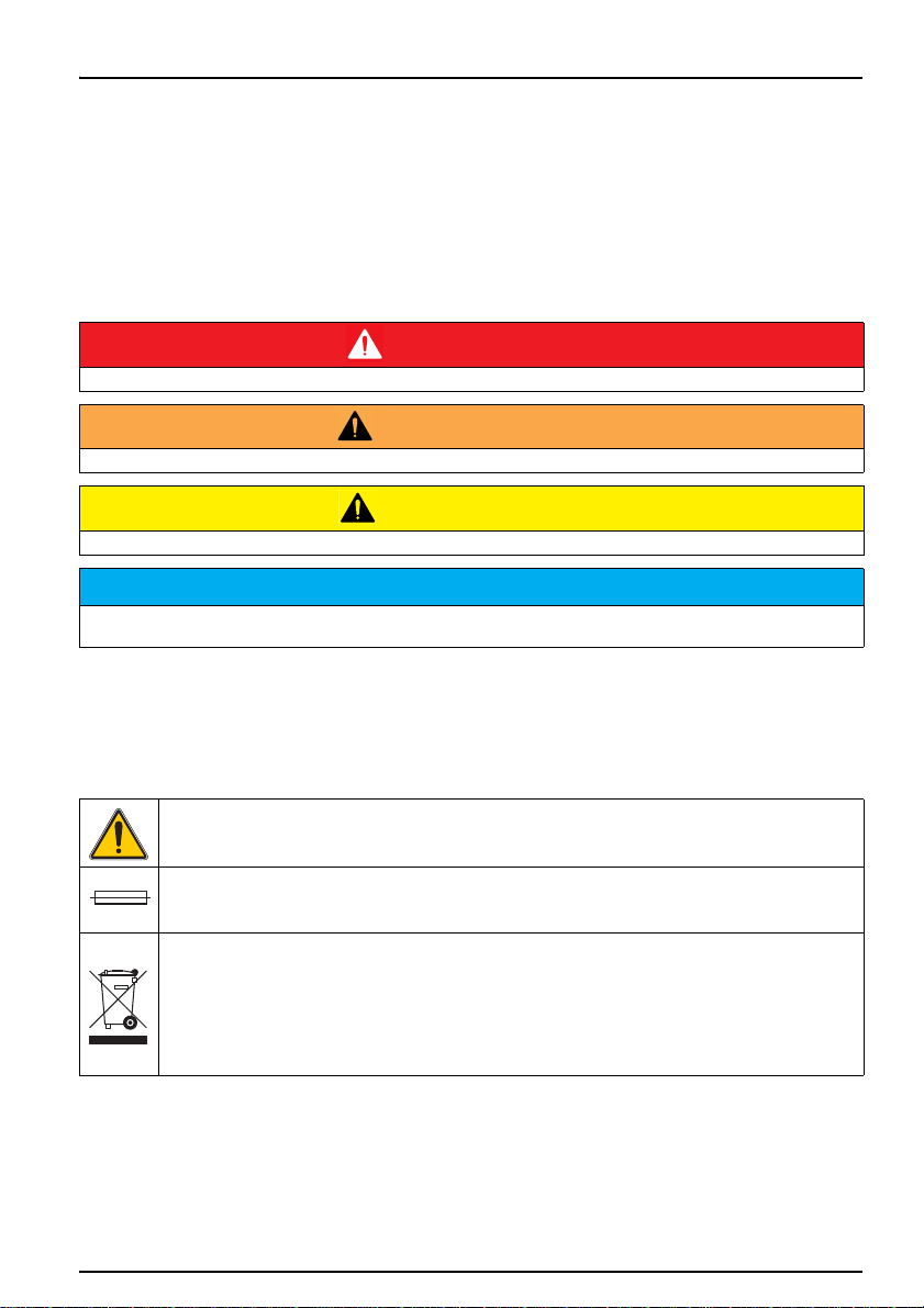
2.1.2 Precautionary Labels
Read all labels and tags attached to the instrument. Personal injury or damage to the instrument
could occur if not observed. A symbol, if noted on the instrument, will be included with a danger or
caution statement in the manual.
This symbol, if noted on the instrument, references the instruction manual for operation
and/or safety information.
This symbol, when noted on the product, identifies the location of a fuse or current limiting device.
Electrical equipment marked with this symbol may not be disposed of in European public disposal
systems after 12 August of 2005. In conformity with European local and national regulations (EU
Directive 2002/96/EC), European electrical equipment users must now return old or end-of life equipment to the Producer for disposal at no charge to the user.
Note: For return for recycling, please contact the equipment producer or supplier for
instructions on how to return end-of-life equipment, producer-supplied electrical
accessories, and all auxiliary items for proper disposal.
6
Page 7
General Information
2.1.3 Chemical and Biological Safety
DANGER
Potential danger with contact with chemical/biological substances.
Working with chemical samples, standards and reagents can be dangerous.
Make yourself familiar with the necessary safety procedures and the correct handling of the chemicals before use
and read and follow all relevant safety data sheets.
Normal operation of this device may require the use of chemicals or samples that are biologically
unsafe.
• Observe all cautionary information printed on the original solution containers and safety data
sheets prior to their use.
• Dispose of all consumed solutions in accordance with the local and national regulations and
laws.
• Select the type of protective equipment suitable to the concentration and quantity of the
dangerous material being used.
DANGER
The BIOGAS Titration Manager has been developed to meet the requirements of volumetric titration applications.
It is therefore aimed at experienced users who have the knowledge required to operate the instrument and implement the security instructions enclosed. Please remember that the BIOGAS Titration Manager must not, under
any circumstances, be used to perform tests on living beings.
WARNUNG
The BIOGAS Titration Manager may not be used in dangerous environments.
The manufacturer and its suppliers reject any express or indirect guarantee for use with high-risk activities.
Follow the following safety information, in addition to any local guidelines in force.
Safety information for the correct use of the instrument:
• Do not vibrate or jolt the instrument.
• Do not open the instrument.
• Guarantee is voided if the instrument is not used in accordance with the guidelines present in
this document.
ACHTUNG
The manufacturer is not responsible for damages resulting from misapplication or misuse of this product and
rejects the regulation of such damages, including direct, indirect and consequential damages, and in full
accordance with applicable law. The user is solely responsible for the identification of critical applications and risks
and taking appropriate measures to protect processes during a possible equipment malfunction.
7
Page 8
Section 3 Installation
DANGER
Only qualified personnel should conduct the tasks described in this section of the manual.
3.1 Unpacking the instruments
The BIOGAS Titration Manager comes packaged with the following items:
• BIOGAS Titration Manager, one burette, zero version
• B525, Burette Stand, 25 mL, red cover with connection tubing
• Accessories for Titration Manager burette stand
• Set of Cables for Tiration Workstation (w/o serial PC Printer cable)
• Cell kit
• Titration Vessel, PP, 40-100 mL (pack of 10 pcs of 956-265)
• Titration Vessel, PP, 22-45 mL (pack of 10 pcs of 956-178)
• User Manual BIOGAS
• Basic User Manual BIOGAS, multilingual
• Method Guide for FOS/TAC (organic acids (FOS) and total inorganic carbon (TAC)), En-Ger
• Installation form (Fr-Eng-Ger)
Note: If any of these items are missing or damaged, contact the manufacturer or a sales
representative immediatly.
3.2 Operating environment
The following conditions are necessary to ensure correct instrument operation and accurate results:
• Place the instrument firmly on an even surface. Do not push any objects under the instrument.
• Maintain an ambient temperature of 5 to 40 ºC (41 to 104 ºF) for proper instrument operation.
• The relative humidity should be less than 80 %; moisture should not condense on the
instrument.
• Leave at least a 15 cm (6 in.) clearance at all sides for air circulation to avoid overheating of
electrical parts.
• Do not operate or store the instrument in extremely dusty, damp or wet locations.
• Keep the surface of the instrument and all accessories clean and dry at all times. Splashes or
spills on the instrument should be cleaned up immediately.
Protect the instrument from temperature extremes, including heaters, direct sunlight and other heat sources.
NOTICE
8
Page 9
Installation
I
O
1
E1E1E2E2
TEMPTEMP
GNDGND
5V OUTV OUT
ININ
T 1A 250VT 1A 250V
TTLTTL
100-240V100-240Vacac
50-60Hz 45VA50-60Hz 45VA
SACSAC AUX.AUX.
REFREFPt-PtPt-Pt
LINE FUSE T1A L250VLINE FUSE T1A L250V
BALANCEBALANCE
PROPELLERPROPELLER
PC/PRINTERPC/PRINTERSLAVESLAVE
30201163020116
Conforms to Conforms to
UL STD 61010A-1 UL STD 61010A-1
Certified to Certified to
CSA STD C22.2 No. 1010.1CSA STD C22.2 No. 1010.1
MADE IN FRANCEMADE IN FRANCE RADIOMETER ANALYTICAL SASRADIOMETER ANALYTICAL SAS
716R999N999716R999N999
3.3 Power connections
Use only a grounded socket for the connection of this device to the power supply. If you are not sure if the sockets are grounded, have this checked by a qualified electrician. The power plug serves in addition to the power
supply to isolate the device quickly from the power source where necessary. During the disconnection from the
power source it must be made sure that the correct power plug is pulled (for example by labeling the sockets).
This is recommended for long-term storage and can prevent potential dangers in the event of a fault. Therefore
make sure that the socket to which the device is connected is easy to reach by each user at all times.
WARNING
Electrical dangers and fire hazard.
Only use the supplied power cable.
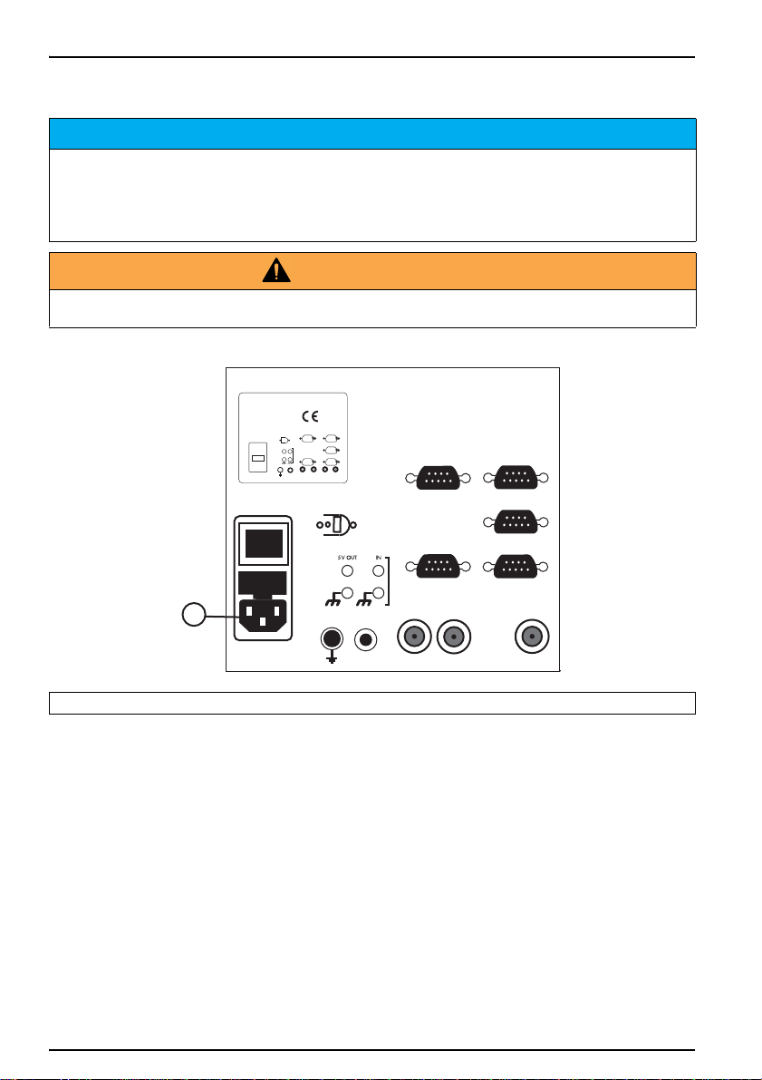
Figure 1 Power connection
NOTICE
1 Power connection
1. Plug the power cable into the back of the instrument (Figure 1).
2. Insert the plug of the power cable into a grounded mains socket (100–240 V~ / 50–60 Hz).
3. Switch the power button to "On" to turn on the instrument (Figure 2, position 13).
9
Page 10
3.4 Interfaces
I
O
1
2
3
4
5
6
78
91011
12
14
13
E1E1E2E2
TEMPTEMP
GNDGND
5V OUTV OUT
ININ
T 1A 250VT 1A 250V
TTLTTL
100-240V100-240Vacac
50-60Hz 45VA50-60Hz 45VA
SACSAC AUX.AUX.
REFREFPt-PtPt-Pt
LINE FUSE T1A L250VLINE FUSE T1A L250V
BALANCEBALANCE
PROPELLERPROPELLER
PC/PRINTERPC/PRINTERSLAVESLAVE
30201163020116
Conforms to Conforms to
UL STD 61010A-1 UL STD 61010A-1
Certified to Certified to
CSA STD C22.2 No. 1010.1CSA STD C22.2 No. 1010.1
MADE IN FRANCEMADE IN FRANCE RADIOMETER ANALYTICAL SASRADIOMETER ANALYTICAL SAS
716R999N999716R999N999
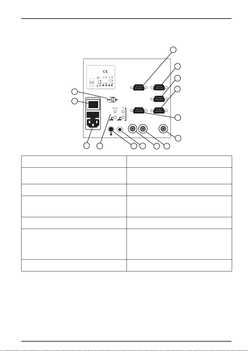
Figure 2 Interfaces
Installation
1 RS232 socket. Not used.
2PC/PRINTER RS232 socket.
PC, cable A95X501
Printer, cables A95P201.
3 RS232 socket. Not used.
4 BALANCE RS232 socket.
Due to the large variety of balance and models,
cables are made on demand, please contact your
local supplier.
5SAC RS232 socket.
Sample changer, cable A95A202
6E1 BNC socket.
Combined pH or ISE electrodes w/wo
temperature sensor,
Single pH or ISE electrodes,
Single or combined metal electrodes (Redox
measurements)
7REF BNC socket.
Reference electrodes
3.5 Installation of burettes and reagents
Refer to:
• BIOGAS Titration Manager Installation form, Catalog Number: D26T044
• BIOGAS Titration Manager Reference Manual, Catalog Number: D21T087,
Section 5 Glossary, keywords «Installing burette» and «Installing reagent»
8Pt-Pt BNC socket.
Double metal electrodes
9TEMP Cinch socket.
Temperature sensors
10 Banana socket. Single metal electrodes for
grounding only
11 Red and black banana sockets
TTL 0 ±5 V input.
Red and black banana sockets
TTL 0 ±5 V output.
12 Power connection socket.
Line cord A95S001/A95S002
13 power button: On/Off switch
14 Socket for propeller stirrer (Catalog Number:
904-480).
10
Page 11

Installation
11
Page 12
Kapitel 4 Startup
4.1 Power the instrument on and off
1. Connect the power cable to a power socket.
2. Switch on the instrument via the power switch on
Note: Always wait about 20 seconds before turning the
instrument on again, otherwisethe electronic and
mechanical systems will be damaged.
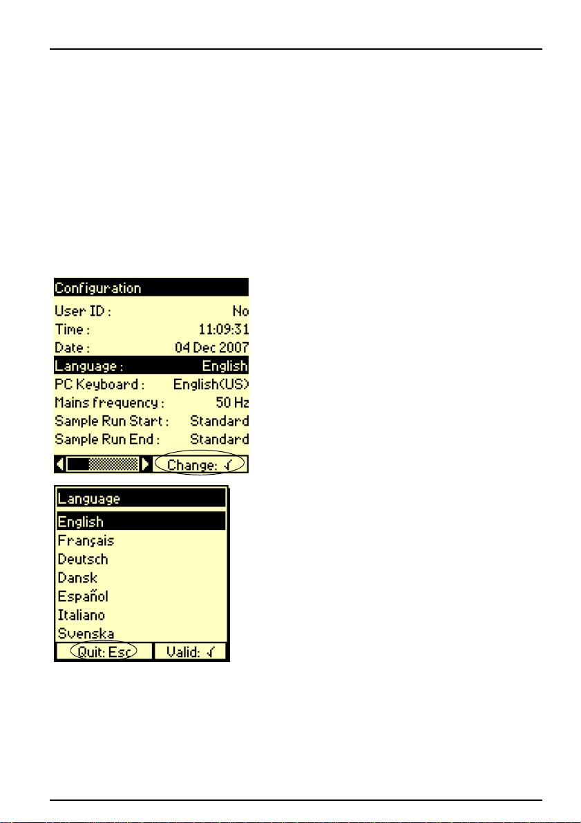
4.2 Language selection
1. Press Stop for 3 seconds in the Main menu.
2. Press 1 to enter the Configuration menu.
3. Select the Language line with the arrow keys and
the back.
The Main menu is displayed.
The Setup menu is displayed.
confirm.
4.3 Display Contrast
4. Select the desired language and confirm.
Note: Esc allows you to leave the screen without
changing the language.
The instrument functions in the selected language until
the option is changed.
If required, you can adjust the contrast of the display:
1. Select the Main menu.
2. Press 0 to increase the brightness, or press 7 to
decrease the brightness.
12
Page 13

Startup
13
Page 14
Kapitel 5 Standard Operations
5.1 Overview
The interface of the BIOGAS Titration Manager has
been specially designed to clearly guide you through
every step of the programming and running of the
analyses, whether you are a supervisor or a routine
user.
An important part of this interface is to check and control
the presence of different elements necessary to run the
defined application.
5.1.1 Use of alphanumerical keypad
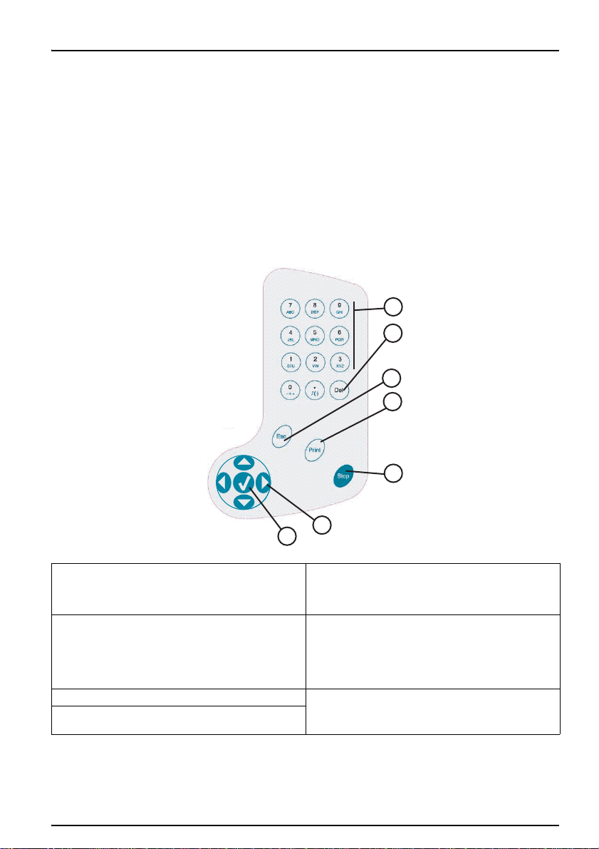
Figure 3 Alphanumerical keypad
1
2
3
4
1 Alphanumeric keypad to enter data and parame-
ters on the same principle as mobile telephones.
These keys can also be used for quick access to
the different menus.
2 Del key: deletes the character on which the
cursor is positioned.
Operator may end the analysis before the max.
titration time or the max. volume have been
reached, if he considers his analysis finished.
Calculations are performed.
3 Esc key: returns to the previous screen.
4Print key: prints the data concerning the screen
displayed.
5
6
7
5 Stop key: stops an analysis or a burette function.
Press this key for 3 seconds in the Main window
to gain access to the setup parameters.
6 RIGHT, LEFT, UP, DOWN arrow keys are used
to move to different options within the menus.
7 Validation/Confirm key : confirms a data entry, a
message or a function asked for by the user.
14
Page 15
Standard Operations
1
3
2
4
5
6
7
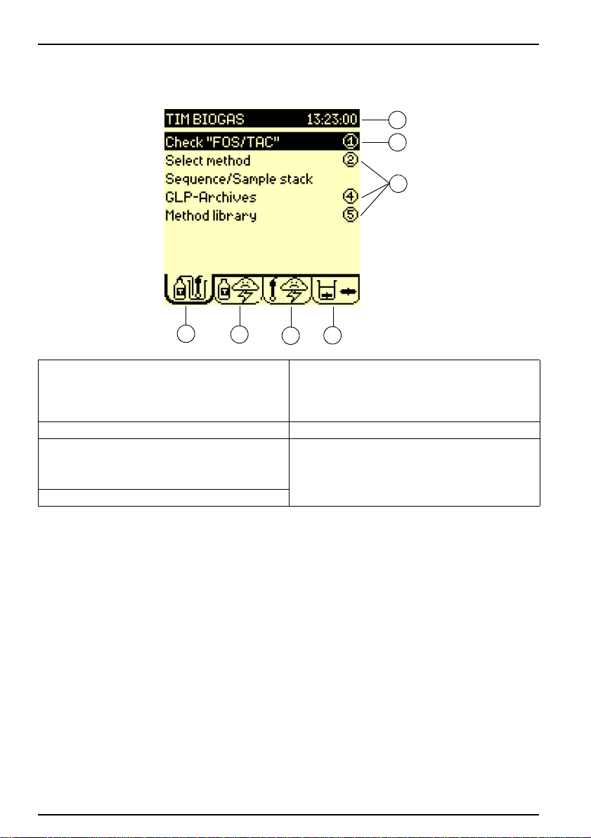
5.1.2 General screen description
Figure 4 General screen description:
1 Title bar.
Indicates the instrument name and the actual
time. You will be shown how to personalise the
name and adjust the time further on in the
manual.
2 Selected line 6 Electrode tab
3 Menu options.
Press the corresponding number for quick access
to the different menus. For example, press 5 to
enter the Method library
4 Method tab
5 Reagent tab
7 Cell tab
Note: The UP and DOWN keys allow you to select a
line. To enter an option, select the line, and press the
validation key. You can also press the corresponding
numerical key.
15
Page 16
5.2 Main menu
1
3
2
4
5
6
7
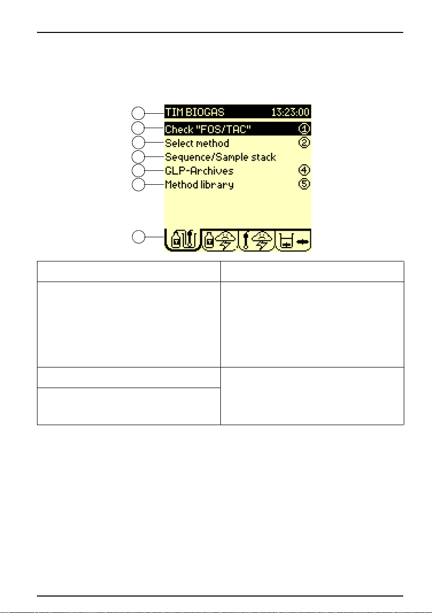
Figure 5 Main menu
Standard Operations
When the instrument is switched on the Main window
is displayed.
1 Title bar: indicates the instruments name and the
current time.
2 Check or Run: check or run the selected method
/sequence. The method can be run when 2 sunny
icons are displayed in the Reagents and
Electrodes tabs.
Note: If a cloudy/stormy icon is displayed,
activate the "Check" command. The
Titration Manager will automatically guide
you through the necessary operations
required to solve the problem(s).
3 Select method: select method and view the main
parameters of that method.
4 Sequence/sample stack: if a Sample Changer is
used and declared in the Configuration menu,
program the sample stack. Select or edit the
sequence.
5.3 Reagent menu
5GLP-Archives: access GLP tables and visualise
the stored method sample results.
6 Method library: supervisor use only: create, edit,
reset and delete methods to correspond to your
specific needs.
7 Method icon: Animated icon indicates when a
method/sequence is running.
Press the RIGHT arrow key in the Main menu to
move to the Reagent menu.
16
Page 17
Standard Operations
1
3
2
4
5
6
7
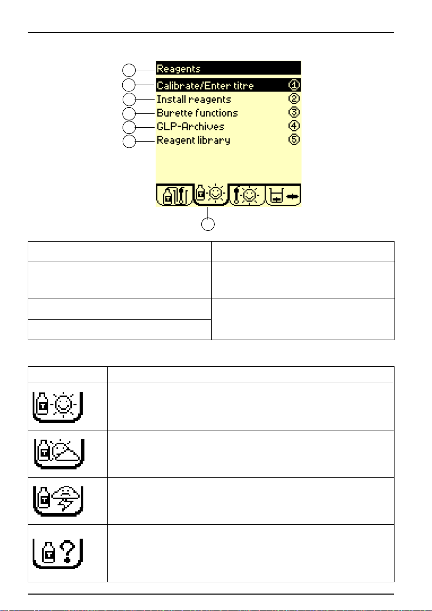
Figure 6 Reagents menu
1 Title bar: indicates the name of the window.
2 Calibrate/Enter titre: determine the
concentration of the titrant (titre) by running a
calibration or a calibration sequence or by
entering the titre manually.
3 Install reagents: install or replace reagents in a
method or a sequence.
4 Burette functions: fill, empty, flush, rinse and
replace burette.
Icon Description
Sunny icon:
The reagent calibration or manual entry of the titre has been performed for all the reagents present in the system. Everything is just right!
Cloudy icon:
The reagent calibration of one of the reagents in the system should be performed within
12 or 24 hours.
Stormy icon:
The reagent calibration of one of the reagents in the system has elapsed.
At least one of the reagents present in the system has not been installed.
Question mark:
There is a problem in the editing of the reagent system. You need to be in Supervisor
mode to solve the problem. Check the sequence/method parameters of the reagent or
the electrode.
Check the sequence or method, (press 1 in the Main window). The instrument indicates
the possible errors and prompts you to correct them until ? disappears.
5GLP-Archives: access GLP tables and visualise
the last reagent calibration results.
6 Reagent library- supervisor use only: create,
edit, reset and delete reagents to correspond to
your specific needs.
7 Reagent icon: Reagent status icon indicates the
state of the reagent system. Four types of icons
can be displayed. See table on the next page.
Table 1 Reagent icons
17
Page 18

5.4 Electrode menu
1
3
2
4
5
6
Figure 7 Electrode menu
Standard Operations
Press twice the RIGHT arrow key in the Main menu to
move to the Electrode menu.
1 Title bar: indicates the name of the window.
2 Calibrate electrode: run a calibration or a
calibration sequence using the installed
electrodes.
3 Display measurement: displays mV and/or pH
and/or temperature at a connected electrode of
the electrode system.
4GLP-Archives: access GLP tables and visualise
the last electrode calibration results.
5 Electrode library- Supervisor use only: create,
edit, reset and delete electrodes stored in the
instrument.
6 Electrode icon: Electrode status icon indicates
the state of the electrode system. Four types of
icons can be displayed. See table on the next
page.
Table 2 Electrode icons
Icon Description
Sunny icon:
The calibration has been performed on the electrode present in the system. Everything
is just right!
Cloudy icon:
The electrode calibration of the electrode present in the system should be performed
within 12 or 24 hours.
Stormy icon:
The calibration date has elapsed for the electrode present in the system.
If acceptance limits have been set for the calibration: at least one calibration result lies
outside the programmed acceptance limits.
18
Page 19

Standard Operations
1
3
2
4
Icon Description
Question mark:
There is a problem in the editing of the electrode system. You need to be in Supervisor
mode to solve the problem. Check the sequence/method parameters of the reagent or
the electrode.
Check the sequence or method, (press 1 in the Main window). The instrument indicates
the possible errors and prompts you to correct them until ? disappears.
5.5 Cell menu
Figure 8 Cell menu
Table 2 Electrode icons
Press three times the RIGHT arrow key in the Main
menu to move to the Electrode menu.
1 Title bar: indicates the name of the window.
2 Internal stirring: command stirrer On/Off (see
Apply internal stirring).
19
3Speed: select the internal stirring speed, from
100 to 1100 rpm by steps of 50 rpm.
4Cell icon: animated icon indicates when the
magnetic stirrer or propeller is operating.
Apply internal stirring
1. Select Internal stirring = ON,
2. In the field Speed, select a stirring speed.
Apply external stirring
1. Connect the Stirring Propeller, part no. 904-480,
to the Titration Manager (see Figure 2 on page
10, position 14).
Line 1 is automatically replaced by External
stirring.
2. Select External stirring = ON.
Page 20

5.6 Setup Menu
1
2
5.6.1 Configuration menu
Figure 9 Configuration menu
Standard Operations
3. Adjust stirring by turning the stirring propeller
knob.
Note: You can consult the corresponding table
between the position (1 to 9) and the stirring
speed by selecting the field Speed setting.
1. Press Stop for 3 seconds in the Main window to
move to the Setup menu.
2. Enter the Supervisor code to differentiate
between the Routine mode and the Supervisor
mode.
• In Routine mode, the user is able to select
and run methods.
• In Supervisor mode, the user can create,
edit, select and run methods. A Supervisor
code is also used to protect your parameters from any unwanted changes.
Note: Continue without entering a Supervisor code.
1. Press 1 to enter the Configuration menu.
1 Use the UP and DOWN arrow keys to select the
parameter.
2 Horizontal scroll bar. The position of the bar
indicates the first screen in the Configuration
menu. Use the RIGHT arrow key to move to the
next screen
Note: The position of the bar indicates the
last screen in the Configuration menu
20
Page 21

Standard Operations
2. Press the RIGHT arrow key to move to the next
screen in the Configuration menu.
3. Press the UP arrow key to scroll in the
Configuration menu.
21
4. Press the LEFT arrow key to return to the first
screen in the Configuration menu.
Page 22

5.6.1.1 Date and time
Standard Operations
1. Select Time in the Configuration menu.
2. Enter the hours (from 00 to 23).
3. Press the RIGHT arrow key.
4. Enter the minutes (from 00 to 59).
5. Press the RIGHT arrow key.
6. Enter the seconds (from 00 to 59).
Note: The LEFT arrow key allows you to return
to the previous screen to modify an entered
value.
7. Press the validation key (as indicated on the
screen).
8. Select Date.
9. Enter the day (from 00 to 31).
10. Press the RIGHT arrow key.
11. Press the UP/DOWN arrow keys to select the
month.
22
Page 23

Standard Operations
5.6.2 Customize the Titration Manager
5.6.2.1 PC keyboard entry
Figure 10 PC Keyboard connection
12. Press the RIGHT arrow key.
13. Enter the year (from 2000 to 2069).
14. Press the validation key (as indicated on the
screen).
You can assign a name to your BIOGAS Titration
Manager, which will be permanently displayed in the
title bar of the Main menu.
1. Connect a PC keyboard to the 6-pin plug
situated on the left hand side of the instrument
(see Figure 10).
23
2. Select PC keyboard in the Configuration
menu.
3. Select English (US).
Note: This allows you to use a QWERTY
keyboard.
4. Press Esc to return to the SETUP menu.
5. Press 3 (Customize).
6. Select the Station parameter by pressing the
validation key.
7. Use the keyboard to enter the desired name.
8. Select the line HACH LANGE GmbH.
This line is used to enter information concerning
the workplace, user(s) name(s), location,
address etc.
Page 24

5.6.2.2 Alphanumerical keypad entry
Standard Operations
9. Enter the text using the PC keyboard (maximum
of 32 characters can be used).
Note: If the characters shown on the display do not
correspond to the ones typed on the keyboard,
redefine your keyboard type. To do this, press Esc
then 1 and select PC keyboard.
1. Press 3 (Customize) in the Setup menu.
2. Select the Station parameter by pressing the
validation key.
3. Example: To replace "TIM BIOGAS" by
"Chem.lab-1", proceed as follows:
a. Press 7 until the letter "C" appears, then
release the key. The cursor moves to the
next position.
b. Press 9 until the letter "h" appears.
c. Continue until you have entered
(em.lab-1).
24
Page 25

Standard Operations
4. To correct a typing error, proceed as follows:
a. Press the LEFT arrow key to position the
cursor on the letter "E".
b. Press 7 to enter the letter "A". The letter E
has been inserted between the letter "A"
and the letter "B".
c. Press Del to delete the "E".
d. Press the validation key to confirm the
entry.
5.6.2.3 Print data
25
1. Enter the Setup window: press Stop 3 seconds
in the Main menu.
2. Enter the Configuration menu: press 1.
3. Press the RIGHT arrow key to move to the
second page in the Configuration menu.
4. Select the Printer = On and confirm.
5. Select
Printer = 80 columns and
Format = Listing or
Page by Page.
6. Enter a User ID if required:
a. In Configuration menu, select User ID =
Yes .
b. You will be prompted to enter a user ID at
the start of a run method. This ID will
appear on the printouts.
7. Enter a Customize the printout if required:
a. In Configuration menu, press 3
(Customize).
b. Enter the name of your workstation (max. 4
lines of 32 characters) (see 5.6.2 on
Page 26
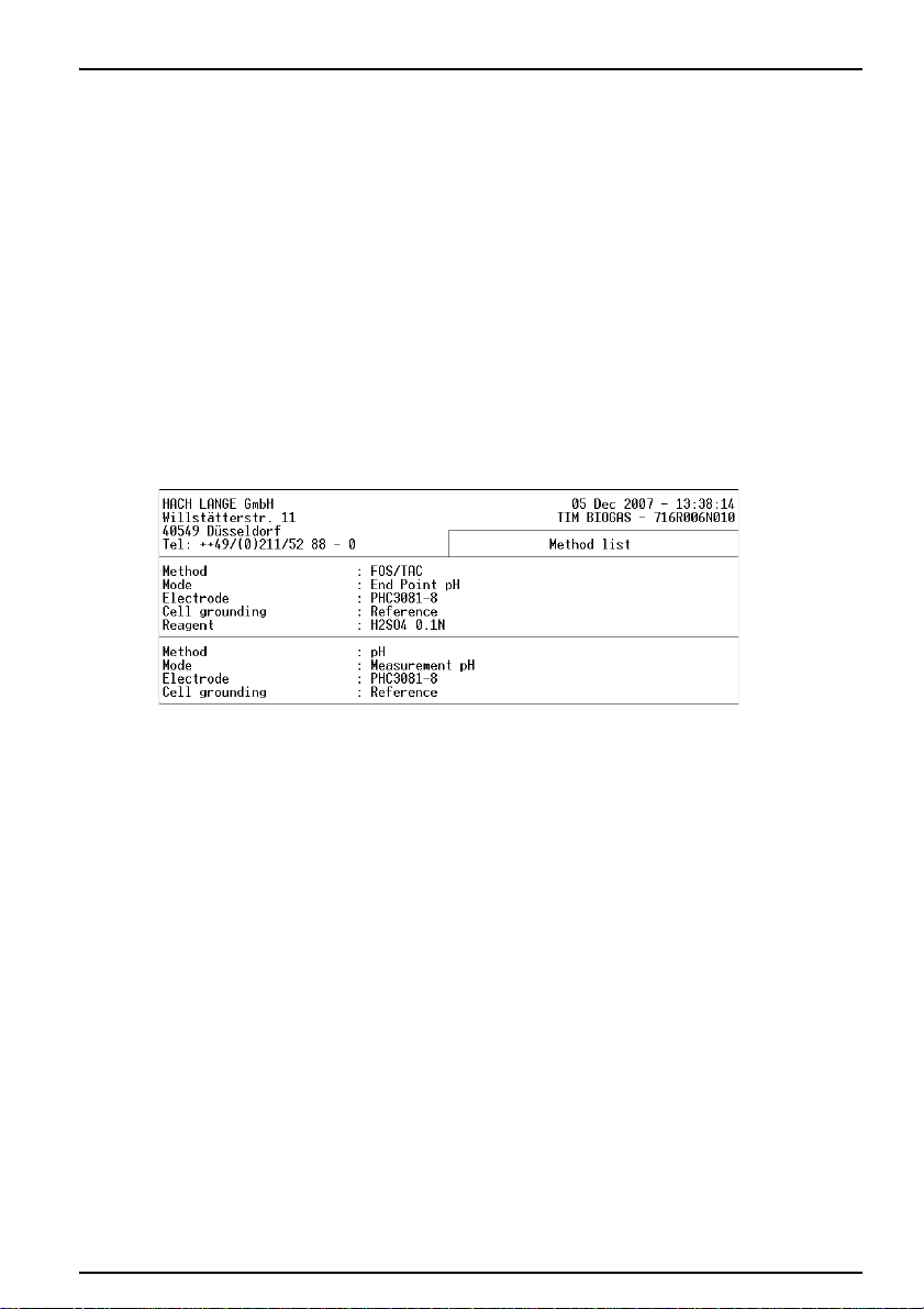
5.7 Manual printouts
Figure 11 Method library
Standard Operations
page 23). This information will appear as a
header at the start of the printout.
8. For automatic printout - select a condensed or
detailed printout.
• In the Printouts screen of the Edit
method/reagent/electrode, select Detailed
= High to obtain a full detailed printout,
• In the Printouts screen of the Edit
method/reagent/electrode, select Detailed
= Low for a condensed printout.
Method library
Press Print, in the Main window to give you an
overview of the methods available in the method list.
5.8 Edit data
5.8.1 Edit method data
Reagent library
Press Print, in the Reagents window to get an
overview of the reagents available in the reagent list.
Electrode library
Press Print, in the Electrodes window to get an
overview of the electrodes available in the electrode
list.
1. In the Main menu, press 5 Method library.
2. Press 2 to access. These are the parameters
entered in the Edit method screen.
3. Press Print to get an overview of the
parameters of the current programmed method.
26
Page 27

Standard Operations
Figure 12 Method data
5.8.2 Edit reagent data
5.8.3 Edit electrode data
27
1. Press 5 Reagent library in the Reagent menu.
2. Press 2 to access. These are the parameters
entered in the Edit reagent screen.
3. Press Print to get an overview of the
parameters of the current programmed
reagent.
1. Press 4 Electrode library in the Electrode
menu
Page 28

5.8.4 Automatic printouts
Standard Operations
2. Press 2 to access. These are the parameters
entered in the Edit electrode screen.
3. Press Print to get an overview of the
parameters of the current programmed
electrode.
The Print key is inactive during a titration, pH/mV
measurement, electrode or reagent calibration.
The results obtained during a "Run" are printed
automatically (see 5.6.2.3 on page 25).
Depending on the option selected for Detailed in the
Edit method/reagent/electrode - Printout screens,
you will obtain different types of printouts.
28
Page 29

Standard Operations
1
2
3
4
5
Figure 13 Example of a printout for a titration
1Header: information entered in the Customize
screen of the Setup window.
2 Analysis ID: User ID and Sample ID entered at
the start of the titration (if option selected during
editing).
3 Title of report: entered in Printouts screen during
method editing.
5.9 Store, send and recall data
5.9.1 The data log
29
4 Calibration data: of the electrode and reagent
used to perform the titration.
5 Titration results: obtained at the end of the
analysis.
The last 60 results are saved in the archives.
Enter the Main window and press 4 GLP-Archives to
access.
Note: The RIGHT and LEFT arrow keys allow you to
move from one screen to the other.
Page 30

Standard Operations
Examples:
Result no. 1/9 = Mean and standard deviation
Mean and standard deviation calculated on "TAC"
test results.
Result no. 1/9 = Mean and standard deviation
Mean and standard deviation calculated on "Volume
A" test results.
Result no. 1/9 = Mean and standard deviation
Mean and standard deviation calculated on "Volume
B" test results.
30
Page 31

Standard Operations
Result no. 1/9 = Mean and standard deviation
Mean and standard deviation calculated on "FOS"
test results.
Result no. 1/9 = Mean and standard deviation
Mean and standard deviation calculated on
"FOS/TAC" test results.
31
Result no. 2/9 = Test no.1
"TAC" result for test no.1.
Page 32

Standard Operations
Result no. 2/9 = Test no.1
"Volume A" result for test no.1.
Result no. 2/9 = Test no.1
"Volume B" result for test no.1.
Result no. 2/9 = Test no.1
"FOS" result for test no.1.
32
Page 33

Standard Operations
5.9.2 The reagent calibration log
Result no. 2/9 = Test no.1
"FOS/TAC" result for test no.1.
The last performed (current) calibration of each
reagent is saved in the archives.
Enter the Reagent menu and press 4 GLP-Archives
to access.
5.9.3 The electrode calibration log
33
The last performed (current) calibration of each
electrode is saved in the archives.
Enter the Electrode menu and press 3
GLP-Archives to access.
Page 34

5.10 Program instructions
5.10.1 Enter a new electrode
Standard Operations
Note: Only the Supervisor is allowed to program the
menus, Electrode, Reagent, and Method.
To select the Supervisor mode:
1. Press Stop for 3 seconds in the Main menu.
2. Enter the Supervisor code (see 5.6 on page 20).
3. Press 5 (Exit).
4. Select Return in mode = Supervisor.
For first time users, it is recommended to program the
instrument as follows:
1. Create the electrode(s) to be used to perform
the measurements.
2. Create the reagent(s) to be used during the
titration.
3. Create the method(s), which will consequently
use the electrode(s) and reagent(s) created in
the first two steps of programming.
4. Once you have finished programming, make
sure that NO question marks "?" are displayed
in the Reagent and Electrode tabs!
1. Enter the Elekctrode menu and press 4
(Electrode library).
34
Page 35

Standard Operations
2. Press 1 (New electrode).
3. Press the validation key in the Function field
4. Select the function of the electrode, refer to the
Table 3.
Table 3 Electrode functions
Electrode type Select function
pH single pH
pH combined w/wo temp. sensor pH pH
Single metal/redox mV (i=0)
Combined metal/redox w/wo temp. sensor mV (i=0)
ISE single mV (i=0)
ISE Combined w/wo temp. sensor mV (i=0)
Reference single Reference
Temperature sensor T°C
Ground metal Ground
Double metal mV (i>0)
5. Press the validation key in the ID field.
6. Select Other in the From field.
Note: The option From = Catalogue allows you
to create an electrode from a list of
preprogrammed electrodes.
7. Enter the identification (ID) of the electrode, (up
to 16 characters).
8. Press 1 twice.
9. Select the electrode Typ e, for electrodes with
pH or mV functions:
•Single pH - pH electrode (no reference
part),
• Combined pH - pH electrode with a refe-
rence part (with or without temperature
sensor),
• Single metal/redox - mV (i=0) function
electrode with a reference part,
• Combined metal/redox - mV (i=0) func-
tion electrode with a reference part (with or
without temperature sensor).
35
Page 36

Standard Operations
Note: When a combined electrode has been
defined, the instrument will prompt you to specify if it
has a built-in temperature sensor or not.
Note: When a single electrode has been defined,
the instrument will prompt you to define a reference
electrode in the Edit electrode screen.
10. When a combined or a reference electrode
has been defined, enter the potential (in mV) of
the reference element versus the Standard
Hydrogen Electrode (SHE).
This parameter enables to run calibration with
automatic buffer recognition when working with
different reference electrode systems. See the
table giving the potential at 25°C versus the
SHE of a few "reference elements/filling
solution" couples (Ta b le 4 ).
Note: When a combined pH or a single pH
electrodes has been defined, enter the internal pH of
the electrode (pH int).
11. Press 1 to confirm.
12. Edit the electrode parameters.
Table 4 Potential versus SHE of Reference electrodes
Reference element filling solution
Hg/Hg
SCE: Saturated Calomel Electrode
Hg/Hg
NCE: Normal Calomel Electrode
Hg/Hg
Hg/Hg
Hg/HgO - 0.1 M KOH +174 mV XR400, XR430, XR440
Ag/AgCl - Saturated KCl +199 mV
Ag/AgCl - 3 M KCl +208 mV
Ag/AgCl - 1 M KCl +235 mV
Ag/AgCl - 0.6 M KCl (sea water) +250 mV
Red Rod - Saturated KCl +199 mV
- Saturated KCl
2Cl2
- 1M LiCl
2Cl2
- Saturated K2SO
2SO4
- 1 M H2SO
2SO4
4
4
Potential versus
SHE
+244 mV
+280 mV REF921
+651 mV
+616 mV
«Catalog list» electrodes
pHC4000, pHC4001, pHC4006, XC601,
REF401, REF421, REF451, XR100, XR110,
XR130, XR150, MC408Pt
REF601, REF621, XR200,
XR230, MC602Pt, MC6091Ag
XR300, XR820, XC100, XC111,
XC120, XC161, XC200, XC250
pHC3001, pHC3005, pHC3006, pHC3011,
pHC3081, pHC3185, REF321, REF361,
MC3051Pt, ISEC301F
pHC2001, pHC2002, pHC2003, pHC2005,
pHC2011, pHC2015, pHC2051, pHC2085,
pHC2401, pHC2441, pHC2501, pHC2601,
pHC2701, REF200, REF201, REF251,
REF261, MC2095Sb, MC201Au-8
36
Page 37

Standard Operations
5.10.1.1 Edit an electrode
1. Enter the Electrode menu and press 4
(Electrode library).
2. Press the validation key and select the
electrode to be edited from the list.
3. Press 2 Edit electrode.
Note: The RIGHT and LEFT arrow keys allow you to
move from one screen to the other.
4. Select whether the electrode should be
calibrated or not (Calibration request = Yes or
No).
Note: If Calibration request = No, the electrode
parameter edition is completed.
Note: Electrode address: indicates which Titration
Manager socket the electrode is connected to:
TIM / E1, Ref, Temp, GND or Pt-Pt.
5. Enter the Periodicity.
Indicates the maximum period of time between
two calibrations. If the period of time is
exceeded, pH measurements can no longer be
performed using this pH electrode. The
electrode must be calibrated.
6. Enter the Number of buffers.
Number of standards (1 to 5) to be used for the
calibration.
7. Select Tem pera ture .
• If a temperature sensor is in use, select
Probe.
• If the temperature is entered manually via
the numeric keypad, select Entered.
• If the calibration is to be performed at 25°C,
select Fixed 25°C.
Note: If you have selected Temperature = Probe, a
temperature sensor must have been selected in the
Parameters screen.
37
Page 38

5.10.1.2 Enter the electrode parameters
5.10.2 Enter a new reagent
Standard Operations
1. Select Calibrate request = yes
2. Enter the electrode definition parameters
3. Go to the last Edit electrode screen.
4. Press 1 and enter the Calibration parameters:
general parameters used during the calibration.
5. Press 2 and enter the Calibration solutions
parameters concerning the standards used for
the calibration.
6. Press 3 and enter the Results parameters
concerning acceptation criteria that you can set
on the results.
7. Press 4 and enter Printouts parameters
defining the calibration report to be printed.
1. Enter the Reagents menu and press 5
(Reagent library).
2. Press 1 New reagent and press the validation
key.
3. Select From = Other.
Note: The option From = Catalogue allows you to
create a reagent from a list of common used
reagents.
4. Select ID and press the validation key.
5. Enter the reagent name (up to 16 characters).
6. Enter the "approximate" titre of the reagent (5
characters) in the Targ et t itr e field.
7. Enter the units (mM, M, mN, N) indicated on the
reagent bottle. Use the following:
mM = mmol/l, M = mol/l, mN = meq/l or
N = eq/l).
Note: Once the units have been confirmed, they
are added to the reagent ID and target titre.
Note: If molar units are selected (mM or M), it is
necessary to enter the stoichiometric coefficients for
the chemical reaction in the Results screen.
8. Press 1 twice to create the reagent.
9. Edit the reagent parameters.
38
Page 39

Standard Operations
5.10.2.1 Edit a reagent
1. Enter the Reagent menu and press 5 (Reagent
library).
2. Press the validation key and select the reagent
to be edited from the list.
3. Press 2 Edit reagent.
Note: The RIGHT and LEFT arrow keys allow you to
move from one screen to the other.
4. Enter the unit: mM = mmol/l, M = mol/l,
mN = meq/l or N = eq/l). The unit is indicated on
the reagent bottle.
5. Select Titre = Enter or Calibrate.
• Select Enter if you already know the titrant
concentration and do not wish to perform a
calibration.
• Select Calibrate if you wish to perform a
calibration. Enter the calibration parameters.
6. Select the type of method for Mode. You have
the choice between End Point, Monotonic IP,
Dynamic IP or Continuous IP.
7. Select the measurement mode for the
calibration (pH, mV or mV at imposed current).
8. Enter the Periodicity.
Indicates the maximum period of time between
two calibrations. If the period of time has
elapsed, titrations can no longer be performed
using this titrant.
9. Enter the Number of tests.
This is the number of times the calibration
method will be repeated, i.e. the number of
beakers to prepare for the calibration.
10. Select Temp erat ure.
• If a temperature sensor is in use, select
Probe.
• If the temperature is entered manually via
the numeric keypad, select Entered.
• If the calibration is to be performed at 25°C,
select Fixed 25°C.
Note: If you have selected Temperature = Probe, a
temperature sensor must have been selected in the
Parameters screen.
Note: If you want a message to be displayed upon
starting the calibration, select Notification = Yes
then enter the message (3 lines of 32 characters
maximum).
39
Page 40

5.10.2.2 Enter the reagent parameters
5.10.3 Enter a new method
Standard Operations
1. Select Titre = Calibrate
2. Enter the Edit reagent menu and press 1
(Calibration parameters).
The Calibration parameters are general
parameters used during the calibration.
3. Press 2 (Standard).
The Standard parameters concerning the
standard solution used for the calibration.
4. Press 3 (Results).
The Results parameters concerning
stoichiometric coefficients for the chemical
reaction (if required).
5. Press 4 (Printouts).
Enter Printouts parameters defining the
calibration report to be printed.
1. Enter the Method menu and press 5 (Method
library).
2. Press 1 New method and press the validation
key.
3. Select ID and press the validation key.
4. Enter a method name (up to 16 characters).
5. Press 1 to confirm.
6. Edit the method parameters.
40
Page 41

Standard Operations
5.10.3.1 Edit a method
1. Enter the Method menu and press 5 (Method
library).
2. Press the validation key and select the method
to be edited from the list.
3. Press 2 Edit method.
Note: The RIGHT and LEFT arrow keys allow you to
move from one screen to the other.
4. Select the method mode. The modes available
are:
• Measurement (pH, mV or mV at imposed
current)
• End point (titration to a preset mV or pH
end point)
• Coupled (methods chained in a same bea-
ker)
• Continuous IP (Inflection point detection
with continuous addition of the titrant)
• Monotonic IP (Inflection point detection
with incremental addition of the titrant,
increments of equal size)
• Dynamic IP (Inflection point detection with
incremental addition of the titrant, increments of varying size)
5. Select the measurement mode:
• pH
• mV
• mV at imposed current.
6. Select Tem pera ture .
• If a temperature sensor is in use, select
Probe.
• If the temperature is entered manually via
the numeric keypad, select Entered.
• If the calibration is to be performed at 25°C,
select Fixed 25°C.
7. Enter the Number of tests, i.e. the number of
times the method is to be repeated.
8. Select the way the cell grounding of the
measuring electrode will be performed:
• Reference: reference electrode connected
to the Ref socket on the titration system.
• Metal: metal electrode connected to the
GND socket on the titration system. For tit-
rations in very resistant medium.
•Other: an electrode which does not belong
to the electrode system.
9. If you want a message to be displayed upon
starting the method, select Notification = Yes
then enter the message (3 lines of 32
characters maximum).
41
Page 42

5.10.3.2 Enter the method parameters
Standard Operations
10. Select Blank:
A blank or blank sample is usually a solvent
used to dissolve or dilute the sample. This blank
may contain traces of the species you are
analysing.
• Select Yes for Blank when you want to subtract the volume of titrant used to titrate the
solvent from the volume found for the dissolved or diluted sample.Enter the unit: mM
= mmol/l, M = mol/l, mN = meq/l or N =
eq/l). The unit is indicated on the reagent
bottle.
1. Enter the Edit method menu and press 1
(Method parameters).
The Method parameters are general
parameters concerning the electrode and
reagent used by the method.
2. Press 2 (Sample).
The Sample parameters concerning the
sample amount analysed.
3. Press 3 (Results).
The Results parameters defining the results
and stoichiometric coefficients for the chemical
reaction (if required).
4. Press 4 (Printouts).
The Printouts parameters defining the analysis
report to be printed.
5.11 Run analyses
5.11.1 Introduction
5.11.1.1 Working in Supervisor mode
When programming in “SUPERVISOR” mode, it is
recommended to work in stages. These stages
should be carried out in the order described below:
1. Define your electrode(s)
42
Page 43

Standard Operations
Icon Description
Identify electrodes (including temperature
sensors) to be used for the analysis.
Electrodes can be created from the following
lists, Catalogue, Other or Copy from. When
creating the electrode, define if electrode
calibration is required (or not), if yes specify the
“periodicity” of the calibrations and the pH
standards to be used. Refer to 5.9.3 The
electrode calibration log on page 33.
2. Define reagent
Identify reagents to be used for the analysis.
Reagents can be created from the following
lists, Catalogue, Other, Copy from. When
creating the reagent, define if reagent calibration
is required (or titre entered manually), if yes
specify the “periodicity” of the calibrations and
the calibration method. Refer to 5.10.2.2 Enter
the reagent parameters on page 40.
Note: If you are to perform a calibration, make sure
that the electrode(s) used for the calibration are the
same as those used in the method.
3. Create a new method or Edit a pre-programmed
one
Create the measurement or titration method to
be used for the analyses. Enter the parameters
required to calculate the results, Refer to
5.10.3.2 Enter the method parameters on page
42.
When you have finished programming, select
the method or pre-programmed application,
refer to Short-Form Reminder no. 3.
If a sample changer is to be used, define the
sample changer in the Configuration menu.
4. Check icons
The following icons indicate the exact state of your
working system.
Table 5 Icons
43
Sunny icon:
Everything is OK. Run the method or sequence.
Note: Sunny icons are required to run the method.
Cloudy icon:
Action required within 12 or 24 hours. For example electrode and/or reagent calibration.
Page 44

Icon Description
Stormy icon:
Electrode/reagent calibration date elapsed or reagent not installed.
Question mark:
It is a programming error, reagent and/or electrode is/are not defined in the selected
method. Revise the method programming.
Standard Operations
Table 5 Icons
Note: When Cloudy/Stormy/Question mark icons
appear, Press 1 Check. The Titration Manager will
automatically guide you through the operations
necessary to solve the errors encountered.
5. Run the method.
5.11.1.2 Working in Routine mode
In “ROUTINE” mode you are guided at every step,
thanks to the clear-text messages and the icons
present on the large graphic display.
A Routine operator has access to all the displays for
checking purposes.
When working in “ROUTINE” mode, it is necessary
to install your titration system according to the
selected method or sequence, prior to running a
method or sequence.
44
Page 45

Standard Operations
1. Press 2 (Select method) in the main menu.
If Question marks "?" are present in the
electrode and/or reagent tabs. Programming
error due to missing electrode/reagent
parameters.
Contact your supervisor.
2. Connect/Check electrode(s).
Refer to Short-Form Reminder no. 1.
Note: When installing/checking an electrode
system, do not forget to connect all the
electrodes to the Titration Manager and
disconnect all the electrodes that are not used
by the method.
3. Install/Check reagent.
Refer to Short-Form Reminder no. 2.
4. Select Start in the main menu to run the
analysis when Sunny icons are visible in the
electrode and reagent tabs.
5. Run an electrode calibration when a Stormy
icon appears in the electrode tab.
6. Run a reagent calibration when a Stormy icon
appears in the titrant tab.
7. If you are unable to display the "Run" command
due to the presence of Cloudy/Stormy icons in
the Reagent and Electrode windows, activate
the "Check" command.
The BIOGAS Titration Manager will
automatically guide you through the necessary
operations required to solve the problem(s).
5.11.2 Run an elecrode calibration
5.11.3 Run a reagent calibration
45
Refer to Short-Form Reminder no. 4.
1. Select the method.
2. Install the electrode group.
3. Enter the Electrode menu.
4. Select 1 Calibrate electrodes.
5. Press the validation key.
6. Select the electrode to be calibrated from the
proposed list.
7. Press 1 to start the calibration.
Refer to Short-Form Reminder no. 5.
1. Select the method.
2. Install the reagent to be calibrated.
3. Install the electrode group to be used to perform
the calibration.
4. Enter the Reagents menu.
5. Select 1 Calibrate/Enter titre.
Page 46

5.11.4 Run a method
5.11.5 Run a sequence
5.11.6 Run a direct measurement
Standard Operations
6. Press the validation key.
7. Select the reagent from the proposed list.
8. Press 1 to start the calibration.
Refer to Short-Form Reminder no. 6.
1. Select the method.
2. Install the electrode group to be used to perform
the analysis.
3. Install the reagent groups to be used to perform
the analysis.
4. Display the Main menu. and press 1 to start the
analysis.
Refer to Short-Form Reminder no. 7.
1. Install the electrode group to be used to perform
the analysis.
2. Install the reagent groups to be used to perform
the analysis.
3. Display the Main menu.
4. Press 3.
5. Press 1.
6. Prepare the sample stack.
7. Display the Main menu and press 1 to start the
analysis.
Refer to Short-Form Reminder no. 8.
1. Select the method.
2. Install the electrode group.
3. Display the Electrode menu.
4. Press 2 to start the measurement.
5. Select the electrode in the list.
Note: You can stop or start stirring by pressing 1.
46
Page 47

Standard Operations
47
Page 48

Section 6 Maintenance
6.1 Cleaning the instrument
The BIOGAS Titration Manager requires minimum maintenance. The exterior surface can be cleaned
with tepid water and wiped dry with a soft cloth.
Note: Never use another solvent.
6.2 Fuse replacement
WARNING
To avoid the risk of electric shock, disconnect the instrument from the power source before the fuse replacement
procedure is commenced.
1. Switch off the instrument.
2. Disconnect line cord.
3. Remove the fuse holder.
4. Replace the used fuses with two new fuses, slow blow, 1.0 A (5 x 20 mm), part no. 450-020.
5. Put the cap back in place.
Figure 14 Fuse replacement
6.3 Servicing
WARNING
Do not attempt to service this product yourself, except as noted in the User’s guide or Reference Manual.
Please contact the service department of the manufacturer or the distributor.
48
Page 49

49
Page 50

Section 7 Troubleshooting
7.1 Troubleshooting
If you have forgotten an operation while editing the method, icons visible in the Electrode and
Reagent windows indicate that an error(s) has occured.
To find out where the error has occured and to help you solve them, run the “Check” command in the
Main window. The BIOGAS Titration Manager will automatically guide you through the operations
required to solve the errors encountered.
50
Page 51

51
Page 52

Section 8 Replacement Parts and Accessories
8.1 Burette stands
Cat. Number
B505 Burette Stand, 5 mL, UV protected with connection tubing X51T026
B510 Burette Stand, 10 mL, UV protected with connection tubing X51T017
B525 Burette Stand, 25 mL, UV protected with connection tubing X51T026
B550 Burette Stand, 50 mL, UV protected with connection tubing X51T028
8.2 Spare parts
Cat. Number
Delivery tubing with anti-diffusion tip X31T069
Titrant bottle stopper GL45 assembly with desiccant & suction tubing X31T070
Titrant bottle stopper GL45 assembly with desiccant & suction tubing for B501 X31T110
Fuse, slow blow, 1.0A, (5 x 20 mm) 450-020
Magnetic stirrer rods x3 LYW 064
Cylinder graduated 5mL 50837
Maintenance Kit of 3 tubes for B5xx X31T115
8.3 Polypropylene titration vessels
Cat. Number
Titration Vessel, PP, 40-100 mL (pack of 50 pcs) 904-490
Titration Vessel, PP, 22-45 mL (pack of 50 pcs) 904-489
8.4 Notebook keyboards
Cat. Number
Notebook Keyboard 83-keys, PS/2 port, US version X16T005
Notebook Keyboard 83-keys, PS/2 port, French X16T006
8.5 Combined pH/Reference electrodes – Acid/Base titrations
Cat. Number
pHC3081-8 - Combined pH electrode, Ag/AgCl, with temperature probe E16M305
8.6 4-7-10 Series pH Standards
Cat. Number
pH 4 - pH 4.00 at 25 °C, 500 ml S11M012
pH 7 - pH 7.00 at 25 °C, 500 ml S11M013
pH 10 - pH 10.00 at 25 °C, 500 ml S11M014
52
Page 53

Replacement Parts and Accessories
8.7 Electrode Maintenance Solutions
Cat. Number
RENOVO N - Normal Cleaning Solution, 250 mL S16M001
RENOVO
KS400 - Pepsin in HCl Cleaning Solution, 250 mL C20C370
KS410 - Thiourea Solution, 250 mL, for junction cleaning C20C380
KS120 - KCl Solution, saturated with AgCl, 500 mL, for Ag/AgCl reference C20C310
GK ANNEX - Electrode Maintenance Kit for pH & reference electrodes S91M001
X - Xtra Strong Cleaning Solution, 250 mL S16M002
8.8 Titrant Solutions
Cat. Number
Sulfuric acid standard solution, 0.1 N, 1000 mL 20253
Hydrochloric acid standard solution, 0.1 N, 1000 mL 1481253
53
Page 54

Section 9 Contact Information
HACH Company
World Headquarters
P.O. Box 389
Loveland, Colorado
80539-0389 U.S.A.
Tel (800) 227-HACH
(800) -227-4224
(U.S.A. only)
Fax (970) 669-2932
orders@hach.com
www.hach.com
HACH LANGE GMBH
Willstätterstraße 11
D-40549 Düsseldorf
Tel. +49 (0)2 11 52 88-320
Fax +49 (0)2 11 52 88-210
info@hach-lange.de
www.hach-lange.de
HACH LANGE GMBH
Rorschacherstrasse 30a
CH-9424 Rheineck
Tel. +41 (0)848 55 66 99
Fax +41 (0)71 886 91 66
info@hach-lange.ch
www.hach-lange.ch
HACH LANGE APS
Åkandevej 21
DK-2700 Brønshøj
Tel. +45 36 77 29 11
Fax +45 36 77 49 11
info@hach-lange.dk
www.hach-lange.dk
HACH LANGE LDA
Av. do Forte nº8
Fracção M
P-2790-072 Carnaxide
Tel. +351 214 253 420
Fax +351 214 253 429
info@hach-lange.pt
www.hach-lange.pt
Repair Service in the
United States:
HACH Company
Ames Service
100 Dayton Avenue
Ames, Iowa 50010
Tel (800) 227-4224
(U.S.A. only)
Fax (515) 232-3835
HACH LANGE LTD
Pacific Way
Salford
GB-Manchester, M50 1DL
Tel. +44 (0)161 872 14 87
Fax +44 (0)161 848 73 24
info@hach-lange.co.uk
www.hach-lange.co.uk
HACH LANGE
FRANCE S.A.S.
8, mail Barthélémy
Thimonnier
Lognes
F-77437 Marne-La-Vallée
cedex 2
Tél. +33 (0) 820 20 14 14
Fax +33 (0)1 69 67 34 99
info@hach-lange.fr
www.hach-lange.fr
HACH LANGE AB
Vinthundsvägen 159A
SE-128 62 Sköndal
Tel. +46 (0)8 7 98 05 00
Fax +46 (0)8 7 98 05 30
info@hach-lange.se
www.hach-lange.se
HACH LANGE SP.
ZO.O.
ul. Krakowska 119
PL-50-428 Wrocław
Tel. +48 801 022 442
Zamówienia: +48 717 177
707
Doradztwo: +48 717 177
777
Fax +48 717 177 778
info@hach-lange.pl
www.hach-lange.pl
Repair Service in
Canada:
Hach Sales & Service
Canada Ltd.
1313 Border Street, Unit 34
Winnipeg, Manitoba
R3H 0X4
Tel (800) 665-7635
(Canada only)
Tel (204) 632-5598
Fax (204) 694-5134
canada@hach.com
HACH LANGE LTD
Unit 1, Chestnut Road
Western Industrial Estate
IRL-Dublin 12
Tel. +353(0)1 460 2522
Fax +353(0)1 450 9337
info@hach-lange.ie
www.hach-lange.ie
HACH LANGE NV/SA
Motstraat 54
B-2800 Mechelen
Tel. +32 (0)15 42 35 00
Fax +32 (0)15 41 61 20
info@hach-lange.be
www.hach-lange.be
HACH LANGE S.R.L.
Via Rossini, 1/A
I-20020 Lainate (MI)
Tel. +39 02 93 575 400
Fax +39 02 93 575 401
info@hach-lange.it
www.hach-lange.it
HACH LANGE S.R.O.
Zastrčená 1278/8
CZ-141 00 Praha 4 Chodov
Tel. +420 272 12 45 45
Fax +420 272 12 45 46
info@hach-lange.cz
www.hach-lange.cz
Repair Service in
Latin America, the
Caribbean, the Far
East, Indian
Subcontinent, Africa,
Europe, or the Middle
East:
Hach Company World
Headquarters,
P.O. Box 389
Loveland, Colorado,
80539-0389 U.S.A.
Tel +001 (970) 669-3050
Fax +001 (970) 669-2932
intl@hach.com
HACH LANGE GMBH
Hütteldorfer Str. 299/Top 6
A-1140 Wien
Tel. +43 (0)1 912 16 92
Fax +43 (0)1 912 16 92-99
info@hach-lange.at
www.hach-lange.at
DR. LANGE
NEDERLAND B.V.
Laan van Westroijen 2a
NL-4003 AZ Tiel
Tel. +31(0)344 63 11 30
Fax +31(0)344 63 11 50
info@hach-lange.nl
www.hach-lange.nl
HACH LANGE S.L.U.
Edificio Seminario
C/Larrauri, 1C- 2ª Pl.
E-48160 Derio/Vizcaya
Tel. +34 94 657 33 88
Fax +34 94 657 33 97
info@hach-lange.es
www.hach-lange.es
HACH LANGE S.R.O.
Roľnícka 21
SK-831 07 Bratislava –
Vajnory
Tel. +421 (0)2 4820 9091
Fax +421 (0)2 4820 9093
info@hach-lange.sk
www.hach-lange.sk
54
Page 55

Contact Information
HACH LANGE KFT.
Vöröskereszt utca. 8-10.
H-1222 Budapest XXII. ker.
Tel. +36 1 225 7783
Fax +36 1 225 7784
info@hach-lange.hu
www.hach-lange.hu
HACH LANGE D.O.O.
Fajfarjeva 15
SI-1230 Domžale
Tel. +386 (0)59 051 000
Fax +386 (0)59 051 010
info@hach-lange.si
www.hach-lange.si
HACH LANGE OOO
Finlyandsky prospekt, 4A
Business Zentrum
“Petrovsky
fort”, R.803
RU-194044,
Sankt-Petersburg
Tel. +7 (812) 458 56 00
Fax. +7 (812) 458 56 00
info.russia@
hach-lange.com
www.hach-lange.com
HACH LANGE S.R.L.
Str. Căminului nr. 3,
et. 1, ap. 1, Sector 2
RO-021741 Bucureşti
Tel. +40 (0) 21 205 30 03
Fax +40 (0) 21 205 30 17
info@hach-lange.ro
www.hach-lange.ro
ΗΑCH LANGE
E.Π.Ε.
Αυλίδος 27
GR-115 27 Αθήνα
Τηλ . +30 210 7777038
Fax +30 210 7777976
info@hach-lange.gr
www.hach-lange.gr
HACH LANGE
8, Kr. Sarafov str.
BG-1164 Sofia
Tel. +359 (0)2 963 44 54
Fax +359 (0)2 866 15 26
info@hach-lange.bg
www.hach-lange.bg
HACH LANGE D.O.O.
Ivana Severa bb
HR-42 000 Varaždin
Tel. +385 (0) 42 305 086
Fax +385 (0) 42 305 087
info@hach-lange.hr
www.hach-lange.hr
HACH LANGE SU
ANALİZ SİSTEMLERİ
LTD .ŞTİ.
Ilkbahar mah. Galip Erdem
Cad. 616 Sok. No:9
TR-Oran-Çankaya/
ANKARA
Tel. +90312 490 83 00
Fax +90312 491 99 03
bilgi@hach-lange.com.tr
www.hach-lange.com.tr
HACH LANGE
MAROC SARLAU
Villa 14 – Rue 2 Casa
Plaisance
Quartier Racine Extension
MA-Casablanca 20000
Tél. +212 (0)522 97 95 75
Fax +212 (0)522 36 89 34
info-maroc@
hach-lange.com
www.hach-lange.ma
55
 Loading...