

Page 1

DOC023.52.03250.May05
5740 sc Galvanic Membrane
Dissolved Oxygen Sensor
User Manual
Page 2

© HACH LANGE GmbH, 2005. All rights reserved. Printed in Germany
Page 3

DOC023.52.03250.May05
5740 sc Galvanic Membrane
Dissolved Oxygen Sensor
User Manual
© HACH LANGE GmbH, 2005. All rights reserved. Printed in Germany
Page 4

Page 5

Table of Contents
Section 1 Specifications ........................................................................................................................................ 3
Section 2 General Information............................................................................................................................... 5
2.1 Safety Information............................................................................................................................................... 5
2.1.1 Use of Hazard Information......................................................................................................................... 5
2.1.2 Precautionary Labels................................................................................................................................. 5
2.2 General Sensor Information................................................................................................................................ 6
2.3 Theory of Operation ........................................................................................................................................... 6
Section 3 Installation .............................................................................................................................................. 7
3.1 Connecting the Sensor to an sc Controller ......................................................................................................... 7
3.1.1 Attaching a sc Sensor with a Quick-connect Fitting .................................................................................. 7
3.2 Installing the Sensor in the Sample Stream........................................................................................................ 8
3.2.1 Sensor Installation Requirements.............................................................................................................. 8
Section 4 Operation ............................................................................................................................................. 11
4.1 Using an sc Controller....................................................................................................................................... 11
4.2 Sensor Setup ................................................................................................................................................... 11
4.3 Sensor Data Logging ........................................................................................................................................ 11
4.4 Pressure and Elevation..................................................................................................................................... 11
4.4.1 Selecting Atmospheric Pressure ............................................................................................................. 12
4.5 SENSOR STATUS Menu.................................................................................................................................. 12
4.6 SENSOR SETUP Menu .................................................................................................................................... 12
4.7 Calibration......................................................................................................................................................... 14
4.7.1 Calibration in Air ...................................................................................................................................... 14
4.7.2 Sample Cal—Calibration by Comparison to a Winkler Titration .............................................................. 15
4.7.3 Sample Cal—Calibration by Comparison to a Hand-held DO Analyzer .................................................. 16
4.7.4 Concurrent Calibration of Two Sensors................................................................................................... 16
Section 5 Maintenance ......................................................................................................................................... 19
5.1 Maintenance Schedule ..................................................................................................................................... 19
5.2 Cleaning the Sensor ......................................................................................................................................... 19
5.2.1 Cleaning the Galvanic Sensor ................................................................................................................. 19
5.3 Preventing the Sensor Membrane from Drying Out.......................................................................................... 19
5.4 Replacing the Sensor Assembly ....................................................................................................................... 20
Section 6 Troubleshooting................................................................................................................................... 21
6.1 Error Codes ...................................................................................................................................................... 21
6.2 Warnings .......................................................................................................................................................... 21
6.3 Sensor Troubleshooting ................................................................................................................................... 22
Section 7 Replacement Parts ............................................................................................................................. 23
7.1 Replacement Items ........................................................................................................................................... 23
7.2 Accessories....................................................................................................................................................... 23
Section 8 Warranty, liability and complaints...................................................................................................... 25
8.1 Compliance Information .................................................................................................................................... 26
Section 9 Adresses ............................................................................................................................................. 27
Appendix A Modbus Register Information
Index....................................................................................................................................................................... 31
........................................................................................................ 29
I
Page 6

Table of Contents
II
Page 7
Section 1 Specifications
Specifications are subject to change without notice.
Components Corrosion-resistant materials, fully-immersible probe with 10 m (30 ft) cable
Measuring Range (Dissolved Oxygen) 0 to 40 ppm (0 to 40 mg/L) or 200 % saturation
Measuring Range (Temperature) – 5 to 50 °C (23–120 °F)
Probe Operating Temperature – 5 to 50 °C (23–120 °F)
Probe Storage Temperature – 5 to 70 °C (23–158 °F); 95 % relative humidity, non-condensing
Response Time at 20 °C 120 seconds to 90 % of value upon step change
Measurement Accuracy ± 2 % of span
Temperature Accuracy ± 0.2 °C
Temperature Compensator 30K NTC Thermistor
Repeatability ± 0.5 % of span
Sensitivity ± 0.5 % of span
Calibration Air/Sample
Maximum Pressure 10 bar (145 psi)
Probe Cable Length Integral 33 ft (10 m)
Probe Weight 0.26 kg (9.1 oz)
Probe Dimensions See Figure 3 Probe Dimensions on page 8.
Wetted Materials Noryl, PVC, Viton, Polypropylene, Nylon
Electrode Materials Nickel-chrome and lead
Minimum Flow Rate 0.5 cm/s (0.016 ft/s)
Measuring Principle Galvanic
3
Page 8

Specifications
4
Page 9
Section 2 General Information
2.1 Safety Information
Please read this entire manual before unpacking, setting up, or operating this equipment.
Pay attention to all danger and caution statements. Failure to do so could result in serious
injury to the operator or damage to the equipment.
Do not use or install this equipment in any manner other than that specified in this manual.
2.1.1 Use of Hazard Information
DANGER
Indicates a potentially or imminently hazardous situation which, if not avoided,
could result in death or serious injury.
CAUTION
Indicates a potentially hazardous situation that may result in minor or moderate
injury.
Important Note: Information that requires special emphasis.
Note: Information that supplements points in the main text.
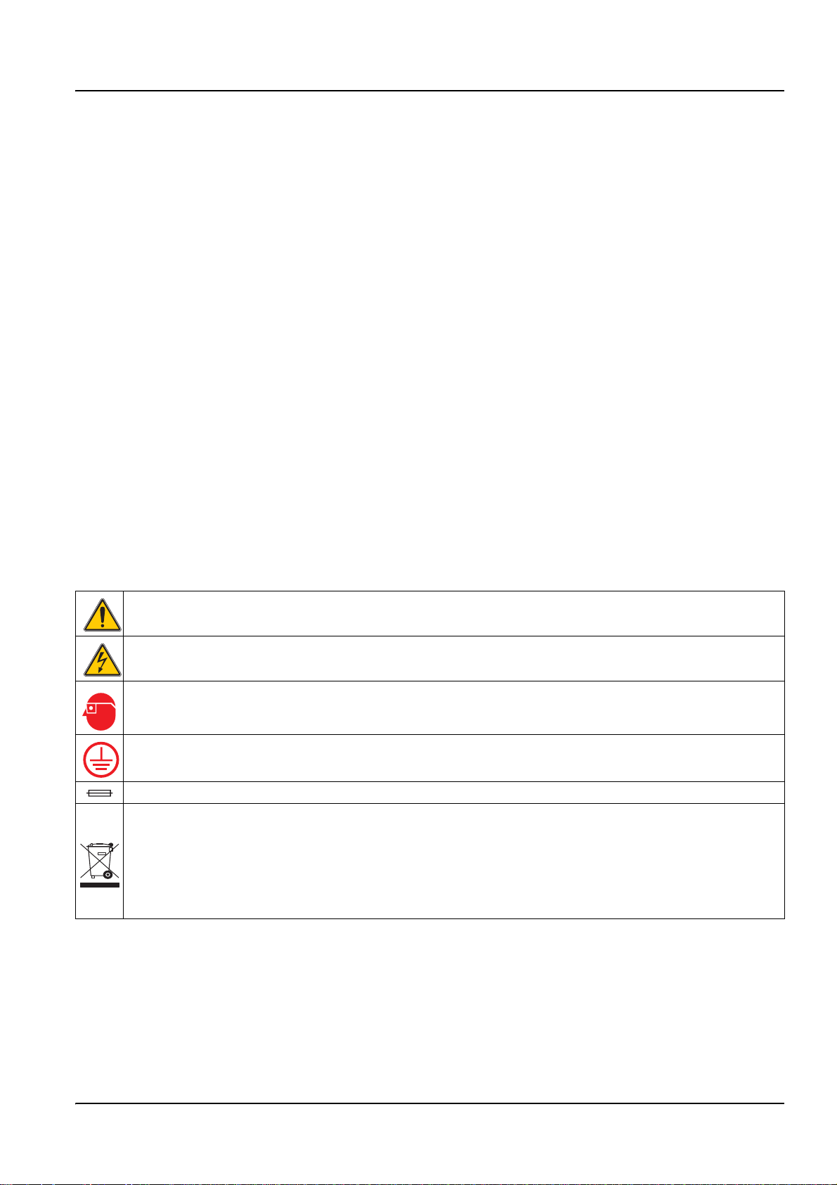
2.1.2 Precautionary Labels
Read all labels and tags attached to the instrument. Personal injury or damage to the
instrument could occur if not observed
This symbol, if noted on the instrument, references the instruction manual for operation and/or safety information.
This symbol, when noted on a product enclosure or barrier, indicates that a risk of electrical shock and/or
electrocution exists.
This symbol, if noted on the product, indicates the need for protective eye wear.
This symbol, when noted on the product, identifies the location of the connection for Protective Earth (ground).
This symbol, when noted on the product, identifies the location of a fuse or current limiting device.
Electrical equipment marked with this symbol may not be disposed of in European public disposal
systems after 12 August of 2005. In conformity with European local and national regulations (EU Directive
2002/96/EC), European electrical equipment users must now return old or end-of life equipment to the
Producer for disposal at no charge to the user.
Note: For all electrical products (marked or unmarked) which are supplied or produced by Hach-Lange, please
contact the local Hach-Lange sales office for instructions for proper disposal.
5
Page 10

General Information
2.2 General Sensor Information
The Galvanic Membrane Dissolved Oxygen Sensor allows aqueous samples to be easily
and accurately analyzed for dissolved oxygen concentration. The system consists of a
controller with an integrated display and a sensor for in-situ measurement.
Optional equipment, such as mounting hardware for the probe, is supplied with
instructions for all user installation tasks. Several mounting options are available, allowing
the probe to be adapted for use in many different applications.
Typical applications include aeration basins, nutrient removal in equalization basins,
aerobic and anaerobic digesters, effluent streams, rivers, lakes, and fish ponds.
2.3 Theory of Operation
This galvanic oxygen sensor operates as a battery generating a voltage. The resulting
voltage is directly proportional to the dissolved oxygen concentration. The cell is
constructed with a fine wire coil cathode wrapped around a lead anode. A salt solution fills
the void between the anode and cathode. The sensor is contained by a cylindrical
membrane held in close proximity to the wire coil.
Oxygen from the solution to be tested enters the cell by diffusion through the membrane
and then across the thin electrolyte layer to the cathode. The oxygen is reduced at the
cathode as shown in reaction 1.
1.
O22H2O4e
++ 4OH
–
→
–
The cathode is at such a negative potential that it reduces all the oxygen that diffuses to its
surface. The lead anode is oxidized to give an overall reaction that produces lead
hydroxide as shown in reaction 2.
2.
2Pb 4OH
–
+ 2Pb OH()24e–+→
The overall result of this reaction is the consumption of the lead anode as current flows,
yielding a very sensitive electrode that can detect changes at the microvolt level.
6
Page 11
Section 3 Installation
DANGER
Only qualified personnel should conduct the installation tasks described in this
section of the manual.
3.1 Connecting the Sensor to an sc Controller
3.1.1 Attaching a sc Sensor with a Quick-connect Fitting
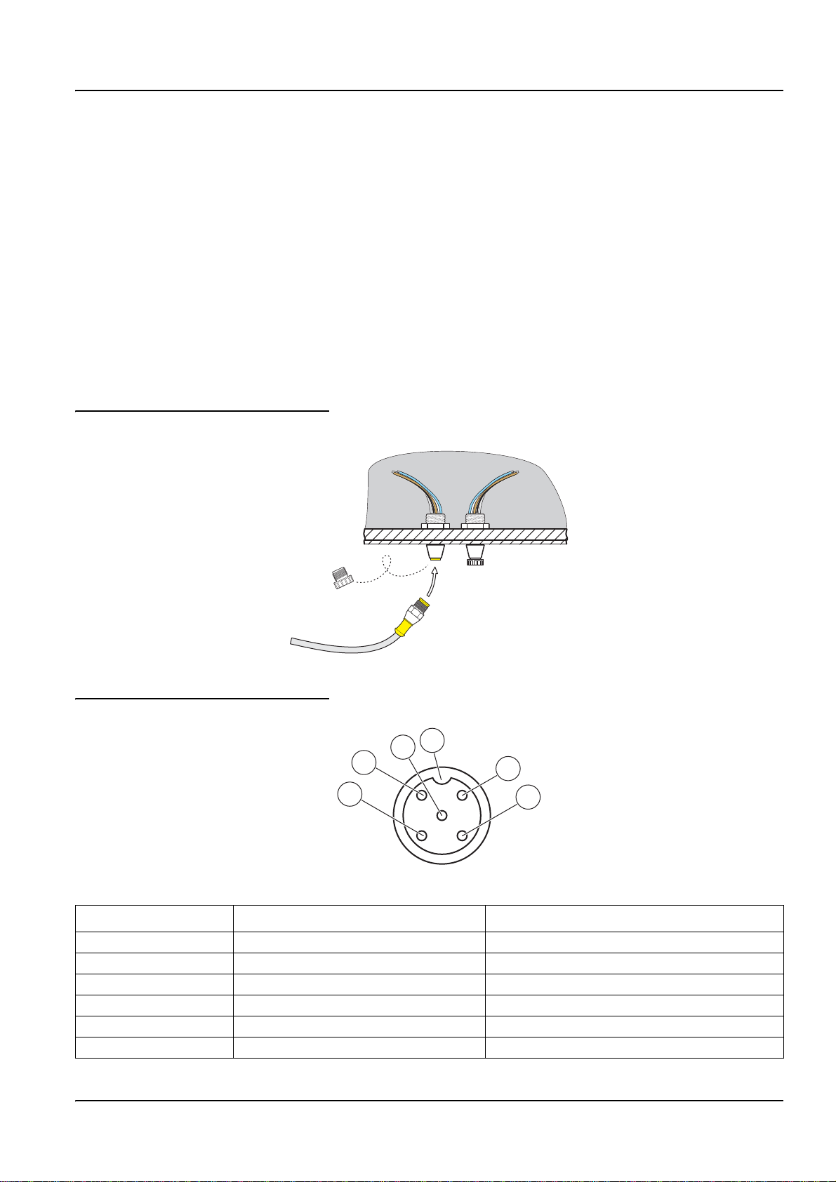
The sensor cable is supplied with a keyed quick-connect fitting for easy attachment to the
controller (Figure 1). Retain the connector cap to seal the connector opening in case the
sensor must be removed. Optional extension cables may be purchased to extend the
sensor cable length. If the total cable length exceeds 100 m (300 ft), a termination box
must be installed.
Note: Use of a load termination box other than Cat. No. 5867000 may result in a hazard.
Figure 1 Attaching the Sensor using the Quick-connect Fitting
Figure 2 Quick-connect Fitting pin assignment
5
4
3
Number Designation Wire Color
1+12 VDC Brown
2 Circuit Common Black
3 Data (+) Blue
4 Data (–) White
5 Shield Shield (grey wire in existing quick-disconnect fitting)
6Groove
6
1
2
7
Page 12

Installation
3.2 Installing the Sensor in the Sample Stream
Each sensor is supplied with a sensor lockring for use with flow tee installations. Replace
the sensor protector with the lockring for those applications.
3.2.1 Sensor Installation Requirements
• Install the sensor so that the sample contacting it is representative of the entire
process.
• Mount the sensor at least 500 mm (20 inches) from the aeration basin wall, and
immerse it at least 500 mm (20 inches) into the process.
• Install the sensor so that its membrane will not be exposed to the atmosphere for more
than 24 hours.
• Do not install the sensor directly over aerators or air diffusers when located in an
aeration basin.
• Install the sensor near the outfall from an aeration basin for most effective aeration
process monitoring and control.
Install the sensor using the instructions supplied with the installation apparatus.
See Figure 3 for sensor dimensions and Figure 4 for suggested mounting configurations.
Figure 3 Probe Dimensions
43.7 mm (1.72 inches)1-inch NPT
37.8 mm (1.49 inches)
172.7 mm (6.80 inches)
203.2 mm (8.00 inches)
8
Page 13

Figure 4 Sensor Installation Examples
Installation
9
Page 14

Installation
10
Page 15

Section 4 Operation
4.1 Using an sc Controller
Before using the sensor in combination with an sc controller make yourself familiar with
the operating mode of the controller. Refer to the controller user manual and learn how to
use and navigate the menu functions.
4.2 Sensor Setup
When a sensor is initially installed, the serial number of the sensor will be displayed as the
sensor name. To change the sensor name refer to the following instructions:
1. Select the Main Menu.
2. From the Main Menu, select SENSOR SETUP and confirm.
3. Select the appropriate sensor if more than one sensor is attached and confirm.
4. Select CONFIGURE and confirm.
5. Select EDIT NAME and edit the name. Confirm or cancel to return to the Sensor
Setup menu.
4.3 Sensor Data Logging
The sc controller provides one data log and one event log for each sensor. The data log
stores the measurement data at selected intervals. The event log stores a variety of events
that occur on the devices such as configuration changes, alarms, warning conditions, etc.
The data log and the event log can be read out in a CSV format. For downloading the logs
please refer to the controller user manual.
4.4 Pressure and Elevation
Note: If the barometric pressure from Table1 is entered in the meter, the altitude entered in
combination with this value must be 0 feet.
Table 1 can be used to estimate the true barometric pressure at certain elevations. The
correspondence is based on the assumption that at sea level the barometric pressure is
760 mm Hg. After determining the barometric pressure from the table or obtaining it from a
local weather service, enter this value into the instrument.
Table 1 Elevation Barometric Pressure
Elevation in feet
(m)
0 760 (1013) 6000 (1829) 613 (817)
500 (152) 746 (995) 6500 (1981) 601 (801)
1000 (305) 733 (977) 7000 (2134) 590 (787)
1500 (457) 720 (960) 7500 (2286) 579 (772)
2000 (610) 708 (944) 8000 (2438) 568 (757)
2500 (762) 695 (927) 8500 (2591) 559 (745)
3000 (914) 683 (911) 9000 (2743) 548 (731)
3500 (1067) 671 (895) 9500 (2896) 538 (717)
4000 (1219) 659 (879) 10000 (3048) 527 (703)
Barometric pressure in mm Hg
(hPa)
Elevation in feet
(m)
Barometric pressure in mm Hg
(hPa)
11
Page 16

Operation
Table 1 Elevation Barometric Pressure
Elevation in feet
(m)
4500 (1372) 647 (863) 10500 (3200) 517 (689)
5000 (1524) 635 (847) 11000 (3353) 506 (675)
5500 (1676) 624 (832)
Barometric pressure in mm Hg
(hPa)
Elevation in feet
(m)
Barometric pressure in mm Hg
4.4.1 Selecting Atmospheric Pressure
1. Select the Main Menu.
2. From the Main Menu, select SENSOR SETUP and confirm.
3. Select the appropriate sensor if more than one sensor is attached and confirm.
4. Select CONFIGURE and confirm.
5. Select AIR PRESS/ALT UNITS and select the appropriate units from the list box.
Confirm the selection.
6. Select AIR PRESS/ALT and tap on the dark-blue highlighted are to the far-right.
Change the value and confirm the selection.
Note: AirPress/Alt must be correct for proper measurement of % saturation and operation of air
calibration.
(hPa)
4.5 SENSOR STATUS Menu
SENSOR STATUS Select Sensor (if more than one sensor is attached)
ERROR LIST See section 6.1 on page 21.
WARNING LIS See section 6.2 on page 21.
4.6 SENSOR SETUP Menu
SENSOR SETUP Select Sensor (if more than one sensor is attached)
CALIBRATE
AIR CAL
SAMPLE CAL
TEMP ADJUST
DEFAULT SETUP
Perform an air calibration of the sensor (slope calibration). See section 4.7.1 on
page 14.
Enter a value for the DO concentration as determined by another sensor or
independent method. The instrument performs an offset calibration based on the
entered value. See section 4.7.2 on page 15.
Displays the measured temperature and allows the user to adjust the temperature by
±15 °C.
Restores the gain and offset values to 1.0 and 0.0, respectively, and restores the
sensor code to default.
12
Page 17

4.6 SENSOR SETUP Menu (continued)
SENSOR SETUP Select Sensor (if more than one sensor is attached)
CONFIGURE
Operation
EDIT NAME
MEAS UNITS
TEMP UNITS Select Celsius (°C) or Fahrenheit (°F); Default: °C
AC FREQUENCY
FILTER Specify the number of seconds for signal averaging (0–60). Default: 0 seconds.
PRESSURE UNITS Choose pressure units in mmHg, feet, meters. Default: mmHg
SET PRESSURE
SALINITY UNITS Choose from mS/cm, mMol/L, ppt, or mg/L. Default: mS/cm
SET SALINITY User-entered value. Default: 0.00 µS/cm
LOG SETUP
TEMP ELEMENT
CAL DAYS Shows the number of days since the last calibration. Default reminder at 60 days.
SENSOR DAYS
DEFAULT SETUP Resets the sensor software to default settings.
Enter up to a 10-digit name in any combination of symbols and alpha or numeric
characters.
Select the appropriate measurement units to display. Choose from: mg/L, ppm,
or percent. Default: ppm
Choose 50 or 60 Hz depending on the power line frequency for optimal noise rejection.
Default is 60 Hz.
Enter either altitude or air pressure. Correlates to the pressure units setting. Range:
–5000 to 15000. Default: 760 mmHg
Disable or choose the datalogging interval for sensor and temperature measurements.
Use the arrow keys to move through the available choices for each. Default: Disabled
Choose SELECT TYPE to specify the temperature sensor that is integrated into the
sensor or choose SET MANUAL to disable automatic temperature compensation.
Default temperature sensor: NTC 30K
Shows the number of days the sensor has been in service. Automatically reminds the
user to replace the sensor after a set period of time. Default reminder at 365 days.
Reset counter in DIAG/TEST/RESET SENSOR menu.
DIAG/TEST
PROBE INFO
SENSOR NAME Displays the entered name of the sensor. Default is the sensor serial number.
SERIAL NUMBER Serial number of the sensor.
SOFTWARE VERS Displays the software version number.
DRIVER VERS Displays the sensor driver version number.
CAL DATA
CAL Q VALUE Display for service diagnostics only.
OFFSET CORR User editable—to change the calibration offset.
LAST CAL DATE Shows the date of the last calibration. Default: 1-1-00
SIGNALS
SENSOR SIGNAL Displays the sensor output in mV.
SENSOR ADC COUNTS Raw data for sensor ADC counts. Comparable to A/D counts.
TEMP ADC CNTS Raw data for temperature ADC counts. Comparable to A/D counts.
COUNTERS
SENSOR DAYS Cumulative days the sensor has been in use.
RESET SENSOR Resets sensor counter.
13
Page 18

Operation
4.7 Calibration
The dissolved oxygen sensor has been calibrated at the factory to the specifications listed
on Specifications on page 3. Due to the inherent accuracy and stability of the luminescent
dissolved oxygen technology, sensor calibration is seldom or never necessary. The
calibration procedures will result in an instrument offset or gain correction and may be
performed if required by regulatory agencies. The air calibration is the most accurate
method. The calibration by comparison method is the least accurate and is therefore not
recommended.
For continued accuracy and repeatability, the manufacturer recommends replacing the
sensor cap after one year of operation.
4.7.1 Calibration in Air
1. Remove the sensor from the process stream and wipe with a wet cloth to remove
2. Place the sensor in the supplied Calibration Bag, add a small amount of water
debris and biological growth.
(25–50 mL) and secure the bag to the sensor body.
3. Lay the bagged probe on a flat surface where it will not be exposed to a heat source.
4. Select the Main Menu.
5. From the Main Menu, select SENSOR SETUP and confirm.
6. Select the appropriate sensor if more than one is attached and confirm.
7. Select CALIBRATE and confirm.
8. Select AIR CAL.
9. Select the available Output Mode (Active, Hold, or Transfer) and confirm.
10. “MOVE THE SENSOR TO AIR” will be displayed if the sensor is moved to air (in the
calibration bag).
11. The Air Calibration procedure will begin and “WAIT TO STABILIZE” will be displayed.
The current DO and temperature readings will be displayed. Confirm to continue.
12. The calibration will automatically occur when the reading stabilizes or when
Confirmation is selected to base the calibration on the currently displayed value. Two
to three minutes for the reading to stabilize is typical, however, if it has not stabilized
after 45 minutes, the display will ready “UNABLE TO CALIBRATE”. After calibration,
one of the responses in
Table 2 Calibration Response on page 17 will be displayed.
14
13. Follow the prompts to return the sensor to the process.
Page 19

4.7.2 Sample Cal—Calibration by Comparison to a Winkler Titration
1. Select the Main Menu.
2. From the Main Menu, select SENSOR SETUP and confirm.
3. Select the appropriate sensor if more than one is attached and confirm.
4. Select CALIBRATE and confirm.
5. Select SAMPLE CAL an confirm.
6. Select the available Output Mode (Active, Hold, or Transfer) and confirm.
Note: An output that has been placed in Hold or Transfer status will be automatically released when
the calibration is complete.
7. Remove the sensor from the process stream and gently wipe with a wet cloth to
remove all debris and biological growth. Remaining debris will affect the Winkler
Method of analysis.
8. Measure 1000 mL of deionized water. Allow the water to come to the thermal and
dissolved oxygen equilibrium (approximately 20 minutes).
Operation
9. Fill a standard BOD bottle and then place the sensor in a beaker containing the
remainder of the deionized water.
10. Perform the Winkler Tritration using Cat. No. 1469-00 Winkler Test Kit on the deionized
water in the BOD bottle while waiting for the process sensor to stabilize.
11. Move the sensor to the sample.
12. The display will show “PRESS ENTER WHEN STABILIZED” and the current DO and
temperature readings. After confirmation or when the reading has been accepted as
stable, the display will change to an entry screen. Without confirmation, the sensor will
determine when the reading is stable. Two to three minutes for the reading to stabilize
is typical, however, if it has not stabilized after 45 minutes, the display will show
“UNABLE TO CALIBRATE”.
13. When a stable reading has been accepted, the display will show “SAMPLE CAL” and
an area for entry of the value obtained from the comparison method. When the entry
screen is displayed, enter the value from the hand-held or winkler titration and confirm.
14. After calibration, one of the responses in Table 2 on page 17 will be displayed.
15
Page 20

Operation
4.7.3 Sample Cal—Calibration by Comparison to a Hand-held DO Analyzer
1. Place the dissolved oxygen sensor as close to the DO sensor as possible.
2. Wait for the hand-held DO analyzer to stabilize.
3. Select the Main Menu.
4. From the Main Menu, select SENSOR SETUP and confirm.
5. Select the appropriate sensor if more than one is attached and confirm.
6. Select CALIBRATE and confirm
7. Select SAMPLE CAL.
8. Select the available Output Mode (Active, Hold, or Transfer) from the list box and
confirm.
9. The display will show “PRESS ENTER WHEN STABILIZED” and the current DO and
temperature readings. After confirmation or when the reading has been accepted as
stable, the display will change to an entry screen. Without confirmation, the sensor
will determine when the reading is stable. Two to three minutes for the reading to
stabilize is typical, however, if it has not stabilized after 45 minutes, the display will
show “UNABLE TO CALIBRATE”.
10. When a stable reading has been accepted, the display will show “SAMPLE CAL” and
an area for entry of the value obtained from the Winkler Titration.
11. Change the displayed reading to match the hand-held DO analyzer memory.
12. After calibration, one of the responses in Table 2 on page 17 will be displayed.
4.7.4 Concurrent Calibration of Two Sensors
1. Begin a calibration on the first sensor and proceed when “WAIT TO STABILIZE” is
displayed.
2. Select the BACK button, then LEAVE. The display will return to the Main
Measurement screen.
3. Begin the calibration for the second sensor and continue until “WAIT TO STABILIZE”
is displayed.
4. Select the BACK button, then LEAVE. The display will return to the Main
Measurement screen and the reading for both sensors will be flashing.
5. To return to the calibration of either sensor, select the Main Menu button. Select
SENSOR SETUP and confirm. Select the appropriate sensor and confirm
.
16
6. The calibration in progress will be displayed. Continue with the calibration.
Page 21

Table 2 Calibration Response
Calibration Response Explanation
CAL COMPLETE Indicates the Calibration is complete.
CAL FAIL, OFFSET HIGH
CAL FAIL, OFFSET LOW
CAL FAIL, UNSTABLE
UNABLE TO CALIBRATE Indicates the Calibration has failed.
Indicates the air calibration has failed due to an excessively high calculated gain value.
Repeat the calibration.
Indicates the air calibration has failed due to too low of a calculated gain value. Repeat the
calibration.
Indicates the air calibration has failed because the readings did not stabilize during the
maximum allowed calibration time interval. Repeat the calibration.
Operation
17
Page 22

Operation
18
Page 23

Section 5 Maintenance
DANGER
Only qualified personnel should conduct the tasks described in this section of the
manual.
5.1 Maintenance Schedule
Maintenance Task 90 days 120 days 365 days
1
Clean the sensor
Inspect sensor for damage x
Replace sensor x
Replace sensor O-rings x
x
Calibrate Sensor (as required by regulatory agency)
1
Cleaning frequency is application dependent. More or less frequent cleaning will be appropriate in some applications.
Per the schedule mandated by your regulatory
agency.
5.2 Cleaning the Sensor
Clean the exterior of the sensor with a stream of water. If debris remains, wipe with a soft,
wet cloth.
5.2.1 Cleaning the Galvanic Sensor
Clean the sensor membrane before each calibration to ensure best results. Clean and
calibrate monthly or until operating experience determines appropriate intervals.
Using a soft wet cloth and mild soap solution, remove all debris from the membrane
surface. Rinse thoroughly with distilled water.
Note: While cleaning the sensor membrane, be careful not to puncture it.
5.3 Preventing the Sensor Membrane from Drying Out
When the sensor is removed from the process solution, its membrane immediately begins
drying out. After more than 24 hours, the electrolyte behind the membrane may become
depleted due to evaporation. If the sensor is returned to operation after this has occurred,
measurement readings may be inaccurate.
Membrane dry-out and electrolyte evaporation can be avoided by temporarily placing the
sensor in a container of clean drinking water until it can be put back into operation.
19
Page 24

Maintenance
5.4 Replacing the Sensor Assembly
The sensor assembly consists of a pre-installed membrane, electrolyte, and electrode.
1. Unscrew the sensor guard or optional lock ring and remove the spent or damaged
sensor assembly.
2. Install the o-ring onto the groove in the probe body, see item 2 and 3 in
Figure 5.
3. Align the sensor assembly connector with the probe body socket, see item 6 in
Figure 5.
4. Reinstall the sensor guard or lock ring.
5. Condition the new sensor before taking measurements. See 4.2 Sensor Setup on
page 11.
Figure 5 Replacing the Sensor Assembly
2
1. Probe Body 4. Sensor Assembly
2. Item 3 seats in groove. 5. Sensor Guard (if sensor guard is not used, install the optional
3. O-ring, (Cat. No. 1857100) 6. Check for connector orientation during assembly.
3145
6
lock ring)
20
Page 25

Section 6 Troubleshooting
6.1 Error Codes
When a sensor is experiencing an error condition, the sensor reading on
the measurement screen will flash and all relays and analog outputs associated with this
sensor will be held. The following conditions will cause the sensor reading to flash:
• Sensor calibration
• Relay timer washing cycle
• Loss of communication
Select the SENSOR STATUS menu and confirm. Select ERRORS and confirm to
determine the cause of the error. Errors are defined in Table 3.
Table 3 Error Codes
Displayed Error Definition Resolution
ADC FAILURE A/D conversion fails.
SENSOR PUNC Sensor punctured.
1
Replacement of the cartridge will reset the read out.
Call the Service Department.
Replace sensor cartridge.1
6.2 Warnings
A sensor warning will leave all menus, relays, and outputs functioning normally, but will
cause a warning icon to flash on the right side of the display. Select WARNINGS and
confirm to determine the cause of the warning.
A warning may be used to trigger a relay and users can set warning levels to define the
severity of the warning.Warnings are defined in Table 4.
Table 4 Warning Codes
Displayed Warning Definition Resolution
PROBE OUT RANGE
TEMP OUT RANGE
FLASH FAILURE Cannot write flash memory. Call the Service Department.
CAL REQUIRED Past the calibration days since last calibration date. Calibrate the sensor.
REPLACE SENSOR Past the total days of current sensor in use. Install new sensor.
No probe connected or measurement reading is out of
range.
No temperature element connected or temperature
reading is out of range.
Check the DO range and ensure that it is
within 0–40 ppm.
Check the temperature range and ensure
that it is within –20 °C to 200 °C.
21
Page 26

Troubleshooting
6.3 Sensor Troubleshooting
Table 5 Sensor Troubleshooting
Problem Cause Resolution
Compare reading to measurement obtained by a
Sensor reading remains at 0 or
max. value for 24 hours or more
Cannot calibrate the sensor
Membrane is punctured
Sensor module or sensor
membrane is bad.
hand-held DO sensor. If different, Replace sensor
cartridge.
Call Customer Service.
Replace sensor cartridge. Recalibrate the sensor.
Call Customer Service.
22
Page 27

Section 7 Replacement Parts
7.1 Replacement Items
Description QTY Catalog Number
5740 sc Galvanic Membrane Dissolved Oxygen Sensor 1 5740D0B
Calibration bags 276M1210
Instruction manual, DO System, English 1 DOC023.52.03250
O-ring, DO probe (0.070 x 0.926 ID) 1 1857100
Sensor Cartridge, replacement, galvanic membrane DO w/thermistor 1 6126700
7.2 Accessories
Description QTY Catalog Number
Air blast cleaning head for 5740 sc galvanic membrane dissolved oxygen sensor 1 6130500
Air blast cleaning system, 115 V, does not include head, order separately 1 6136100
Air blast cleaning system, 230 V, does not include head, order separately 1 6136200
Cable, sensor extension, 0,35 m 1 LZX847
Cable, sensor extension, 5 m 1 LZX848
Cable, sensor extension, 10 m 1 LZX849
Cable, sensor extension, 15 m 1 LZX850
Cable, sensor extension, 20 m 1 LZX851
Cable, sensor extension, 30 m 1 LZX852
Cable, sensor extension, 50 m 1 LZX853
Electrolyte Solution (60 mL bottle) 1 25M7A1002-105
Technical Data, Tank Rim Mount LZX914.99.xxxxx 1 DOC053.99.03262
Mounting hardware kit, pipe 1 5794400
Mounting hardware kit, ball float 1 5794300
Plug, sealing, conduit opening 1 5868700
Strain relief, Heyco 1 16664
Termination Box 1 5867000
Winkler titration kit 1 146900
23
Page 28

Replacement Parts
24
Page 29

Section 8 Warranty, liability and complaints
HACH LANGE GmbH warrants that the product supplied is free of material and
manufacturing defects and undertakes the obligation to repair or replace any defective
parts at zero cost.
The warranty period for instruments is 24 months. If a service contract is taken out within
6 months of purchase, the warranty period is extended to 60 months.
With the exclusion of the further claims, the supplier is liable for defects including the lack
of assured properties as follows: all those parts that can be demonstrated to have become
unusable or that can only be used with significant limitations due to a situation present
prior to the transfer of risk, in particular due to incorrect design, poor materials or
inadequate finish will be improved or replaced, at the supplier's discretion. The
identification of such defects must be notified to the supplier in writing without delay,
however at the latest 7 days after the identification of the fault. If the customer fails to notify
the supplier, the product is considered approved despite the defect. Further liability for any
direct or indirect damages is not accepted.
If instrument-specific maintenance and servicing work defined by the supplier is to be
performed within the warranty period by the customer (maintenance) or by the supplier
(servicing) and these requirements are not met, claims for damages due to the failure to
comply with the requirements are rendered void.
Any further claims, in particular claims for consequential damages cannot be made.
Consumables and damage caused by improper handling, poor installation or incorrect use
are excluded from this clause.
HACH LANGE GmbH process instruments are of proven reliability in many applications
and are therefore often used in automatic control loops to provide the most economical
possible operation of the related process.
To avoid or limit consequential damage, it is therefore recommended to design the control
loop such that a malfunction in an instrument results in an automatic change over to the
backup control system; this is the safest operating state for the environment and the
process.
25
Page 30

Warranty, liability and complaints
8.1 Compliance Information
Hach LANGE GmbH certifies this instrument was tested thoroughly, inspected and found
to meet its published specifications when it was shipped from the factory.
The Galvanic Membrane Dissolved Oxygen Probe with the sc100 and sc1000 has
been tested and is certified as indicated to the following instrumentation standards:
Product Safety
UL 61010A-1 (ETL Listing # 65454)
CSA C22.2 No. 1010.1 (ETLc Certification # 65454)
Certified by Hach Co. to EN 61010-1 Amds. 1 & 2 (IEC1010-1) per 73/23/EEC,
supporting test records by Intertek Testing Services.
Immunity
This equipment was tested for industrial level EMC per:
EN 61326 (EMC Requirements for Electrical Equipment for Measurement, Control
and Laboratory Use)
Company, certified compliance by Hach Company.
per 89/336/EEC EMC: Supporting test records by Hach
Emissions
Standards include:
IEC 1000-4-2:1995 (EN 61000-4-2:1995) Electrostatic Discharge Immunity
(Criteria B)
IEC 1000-4-3:1995 (EN 61000-4-3:1996) Radiated RF Electromagnetic Field
Immunity (Criteria A)
IEC 1000-4-4:1995 (EN 61000-4-4:1995) Electrical Fast Transients/Burst (Criteria B)
IEC 1000-4-5:1995 (EN 61000-4-5:1995) Surge (Criteria B)
IEC 1000-4-6:1996 (EN 61000-4-6:1996) Conducted Disturbances Induced by RF
Fields (Criteria A)
IEC 1000-4-11:1994 (EN 61000-4-11:1994) Voltage Dip/Short Interruptions
(Criteria B)
Additional Immunity Standard/s include:
ENV 50204:1996 Radiated Electromagnetic Field from Digital Telephones (Criteria A)
This equipment was tested for Radio Frequency Emissions as follows:
Per 89/336/EEC EMC: EN 61326:1998 (Electrical Equipment for measurement,
control and laboratory use—EMC requirements) Class “A” emission limits. Supporting
test records by Hewlett Packard, Fort Collins, Colorado Hardware Test Center (A2LA #
0905-01) and certified compliance by Hach Company.
26
Standards include:
EN 61000-3-2 Harmonic Disturbances Caused by Electrical Equipment
EN 61000-3-3 Voltage Fluctuation (Flicker) Disturbances Caused by Electrical
Equipment
Additional Emissions Standard/s include:
EN 55011 (CISPR 11), Class “A” emission limits
Page 31

Section 9 Adresses
HACH LANGE GmbH
Willstätterstraße 11
D-40549 Düsseldorf
Tel. +49 (0) 211- 52 88 - 0
Fax +49 (0) 211- 52 88 - 143
info@hach-lange.de
www.hach-lange.de
DR. BRUNO LANGE
GES. MBH
Industriestraße 12
A-3200 Obergrafendorf
Tel. +43 (0) 2747 - 74 12
Fax +43 (0) 2747 - 42 18
info@hach-lange.at
www.hach-lange.de
DR. LANGE NEDERLAND B.V.
Laan van Westroijen 2a
NL-4003 AZ Tiel
Tel. +31(0)3 44 63 11 30
Fax +31(0)3 44 63 11 50
info@hach-lange.nl
www.hach-lange.nl
HACH LANGE LTD
Pacific Way
Salford
Manchester, M50 1DL
Tel. +44 (0)161 8 72 14 87
Fax +44 (0)161 8 48 73 24
info@hach-lange.co.uk
www.hach-lange.co.uk
DR. BRUNO LANGE AG
Juchstrasse 1
CH-8604 Hegnau
Tel. +41 (0)44- 9 45 66 10
Fax +41 (0)44- 9 45 66 76
info@hach-lange.ch
www.hach-lange.ch
HACH LANGE AB
Vinthundsvägen159A
S-128 62 Sköndal
Tel. +46 (0)8 7 98 05 00
Fax +46 (0)8 7 98 05 30
info@hach-lange.se
www.hach-lange.se
HACH LANGE
HACH SAS
33, Rue du Ballon
F-93165 Noisy Le Grand
Tél. +33 (0)1 48 15 8080
Fax +33 (0)1 48 15 80 00
info@hach-lange.fr
www.hach-lange.fr
HACH LANGE SA
Motstraat 54
B-2800 Mechelen
Tél. +32 (0)15 42 35 00
Fax +32 (0)15 41 61 20
info@hach-lange.be
www.hach-lange.be
HACH LANGE A/S
Åkandevej 21
DK-2700 Brønshøj
Tel. +45 36 77 29 11
Fax +45 36 77 49 11
info@hach-lange.dk
www.hach-lange.dk
HACH LANGE S.L.U.
C/Araba 45, Apdo. 220
E-20800 Zarautz/Guipúzcoa
Tel. +34 9 43 89 43 79
Fax +34 9 43 13 02 41
info@hach-lange.es
www.hach-lange.es
HACH LANGE S.R.O.
Lešanská 2a/1176
CZ-141 00 Praha 4
Tel. +420 272 12 45 45
Fax +420 272 12 45 46
info@hach-lange.cz
www.hach-lange.cz
HACH LANGE SP.ZO.O.
ul. Opolska 143 a
PL-52-013 Wroclaw
Tel. +48 71 3 42 10-81
Fax +48 71 3 42 10-79
info@hach-lange.pl
www.hach-lange.pl
HACH LANGE S.R.O.
Sabinovská 10
SK-821 02 Bratislava
Tel. +421 2 4820 9091
Fax +421 2 4820 9093
info@hach-lange.sk
www.hach-lange.com
HACH LANGE S.R.L.
Via Riccione, 14
I-20156 Milano
Tel. +39 02 39 23 14-1
Fax +39 02 39 23 14-39
info@hach-lange.it
www.hach-lange.it
HACH LANGE LDA
Rua dos Malhões,
Edif. D. Pedro I
P-2770-071 Paço D'Arcos
Tel. +351 210 00 1750
Fax +351 210 00 8140
info@hach-lange.pt
www.hach-lange.pt
27
Page 32

Adresses
28
Page 33

Appendix A Modbus Register Information
Table 6 Sensor Modbus Registers
Group Name Tag Name Register # Data Type Length R/W Description
Tags SensorMeasTag 40001 Integer 1 R Sensor Measurement Tag
Measurements DOMeas 40002 Float 2 R DO Measurement
Tags TempMeasTag 40004 Integer 1 R Temperature Measurement Tag
Measurements TempDegCMeas 40005 Float 2 R Temperature Measurement
Configuration SensorName 40007 String 6 R/W Sensor Name
Tags FuncCode 40013 Integer 1 R/W Function Code tag
Tags NextState 40014 Integer 1 R/W Next State Tag
Configuration TempUnits 40015 Integer 1 R/W Temperature Units—C or F
Configuration Filter 40016 Integer 1 R/W Sensor Filter
Configuration TempElementType 40017 Integer 1 R/W Temperature Element Type
Tags TempUserValueTag 40018 Integer 1 R Temperature User Value Tag
Configuration TempUserDegCValue 40019 Float 2 R/W Temperature User Value
Configuration PressureUnits 40021 Integer 1 R/W Pressure Units
Configuration SalinityUnits 40022 Integer 1 R/W Salinity Units
Tags PressureTag 40023 Integer 1 R Pressure Tag
Configuration Pressure 40024 Float 2 R/W Pressure
Tags SalinityTag 40026 Integer 1 R Salinity Units
Configuration Salinity 40027 Float 2 R/W Salinity
Configuration MeasUnits 40029 Integer 1 R/W Measurement Units
Calibration OutputMode 40030 Integer 1 R/W Output Mode
Calibration CalLeave 40031 Integer 1 R/W Cal Leave Mode
Calibration CalAbort 40032 Integer 1 R/W Cal Abort Mode
Tags CalEditValueTag 40033 Integer 1 R Cal Edit Value Tag
Calibration CalEditDOValue 40034 Float 2 R/W Cal Edit Value
Diagnostics SoftwareVersion 40036 String 6 R Software Version
Diagnostics SerialNumber 40042 String 6 R Serial Number
Diagnostics CalQValue 40048 Float 2 R DO Cal Q Value
Calibration CalCode 40050 Integer 1 R Cal Code
Configuration SensorLogInterval 40051 Integer 1 R/W Sensor Data Log Interval
Configuration TempLogInterval 40052 Integer 1 R/W Temperature Data Log Interval
Diagnostics DOmV 40053 Float 2 R DO mV
Diagnostics ProdDate 40055 Date 2 R/W Production Date
Diagnostics LastCalDate 40057 Date 2 R Last Calibration Date
Diagnostics SensorDays 40059 Integer 1 R Sensor Run\ning Days
Configuration RejectFrequency 40060 Integer 1 R/W Reject Frequency
Diagnostics DeviceDriver 40061 String 5 R Device Driver
Configuration CalWarningDays 40066 Integer 1 R/W Calibration Warning Days
Configuration SensorWarningDays 40067 Integer 1 R/W Sensor Warning Days
29
Page 34

Modbus Register Information
30
Page 35

Index
A
Applications .................................................................... 6
Attaching the Sensor ...................................................... 7
C
Calibration .................................................................... 11
Air........................................................................... 16
Cleaning
Sensor.................................................................... 19
Compliance Information................................................ 26
E
Error Codes .................................................................. 21
M
Maintenance Schedule................................................. 19
S
Safety Information .......................................................... 5
Sensor Cable
Connecting............................................................... 7
Wiring....................................................................... 7
Specifications ................................................................. 3
T
Theory of Operation ....................................................... 6
W
Warnings ...................................................................... 21
31
Page 36

Index
32
 Loading...