

Page 1
DOC342.53.80488
TU5200
03/2017, Edition 3
User Manual
Page 2

Page 3

Table of Contents
Specifications.............................................................................................................. 3
General information.................................................................................................. 4
Safety information........................................................................................................ 4
Use of hazard information.................................................................................... 4
Precautionary labels............................................................................................. 5
Class 2 laser product............................................................................................ 5
RFID module........................................................................................................ 6
Safety information for RFID modules............................................................ 6
FCC conformance for RFID........................................................................... 7
Certification........................................................................................................... 7
Product overview......................................................................................................... 8
Product components.................................................................................................... 8
Installation..................................................................................................................... 9
Installation guidelines.................................................................................................. 9
Connect to external devices (optional)........................................................................ 9
User interface and navigation............................................................................ 10
Startup........................................................................................................................... 11
Operation..................................................................................................................... 12
Configuration............................................................................................................. 12
Configure the instrument settings....................................................................... 12
Change the language.................................................................................. 13
Add operator IDs................................................................................................ 13
Configure an operator RFID tag (optional).................................................. 14
Add sample IDs.................................................................................................. 14
Import sample IDs (optional)....................................................................... 14
Configure the measurement settings.................................................................. 15
Set the acceptance range................................................................................... 15
Set up a LAN connection.................................................................................... 16
Connect to an FTP server or Netdrive......................................................... 16
Connect to a network printer....................................................................... 17
Connect to an sc controller.......................................................................... 17
Measurement............................................................................................................. 18
Sample collection............................................................................................... 18
Prevent vial contamination................................................................................. 18
Prepare a sample vial......................................................................................... 19
Put the vial in the instrument.............................................................................. 20
Measure the sample........................................................................................... 21
Compare process and laboratory measurements.............................................. 21
Collect a grab sample.................................................................................. 21
Compare measurements with RFID............................................................ 21
Compare measurements with Link2SC....................................................... 22
Show the recorded data............................................................................................. 24
Show the instrument information............................................................................... 25
Calibration................................................................................................................... 26
Configure the calibration settings.............................................................................. 26
1
Page 4

Table of Contents
Calibrate the instrument............................................................................................. 26
Verification.................................................................................................................. 28
Configure the verification settings.............................................................................. 28
Do a calibration verification........................................................................................ 28
Maintenance............................................................................................................... 28
Clean spills................................................................................................................ 29
Clean the instrument.................................................................................................. 29
Clean a sample vial................................................................................................... 29
Clean the vial compartment....................................................................................... 30
Troubleshooting....................................................................................................... 30
Remove air bubbles from the sample........................................................................ 34
Condensation............................................................................................................. 34
Replacement parts and accessories............................................................... 34
2
Page 5
Specifications
Specifications are subject to change without notice.
Specification Details
Measurement method Nephelometry with the scattered light collected at a 90° angle to the incident light
Primary compliance method EPA approved Hach Method 10258
Dimensions (W x D x H) 41 x 28 x 12.5 cm (16 x 11 x 7.7 in.)
Weight 2.37 kg (5.23 lb)
Enclosure IP20
Protection class Instrument: III; Power supply: II
Pollution degree 2
Installation category II
Power requirements Instrument: 15 VDC, 2 A; Power supply: 100 to 240 VAC, 50/60 Hz
Operating temperature 10 to 40 °C (50 to 104 °F)
Storage temperature –30 to 60 °C (–22 to 140 °F)
Humidity 5 to 95% relative humidity, non-condensing
Display 17.8 mm (7 in.) color touch screen
Laser Class 2 laser product: Contains a non user-serviceable class 2 laser.
Optical light source 650 nm, maximum 0.43 mW
Measurement units NTU, FNU, TE/F, FTU, EBC, mg/L, mNTU2 or mFNU
Range 0 to 700 NTU, FNU, TE/F, FTU; 0 to 100 mg/L; 0 to 175 EBC
Accuracy ± 2% of reading plus 0.01 NTU from 0 to 40 NTU
Linearity Better than 1% for 0 to 40 NTU on Formazin at 25 °C (77 °F)
Precision < 40 NTU: 0.002 NTU or 1% (the larger value); > 40 NTU: 3.5% based on
Stray light < 0.01 NTU
Calibration options StablCal®: 1-point calibration (20 NTU) for 0 to 40 NTU measurement range; 2-
and 360° around the sample vial.
1
± 10% of reading from 40 to 700 NTU based on Formazin primary standard at
25 °C (77 °F)
Formazin primary standard at 25 °C (77 °F)
point calibration (20 and 600 NTU) for 0 to 700 NTU (full) measurement range
Formazin: 2-point calibration (20 NTU and dilution water) for 0 to 40 NTU
measurement range; 3-point calibration (20 NTU, 600 NTU and dilution water) for
0 to 700 NTU (full) measurement range
Degrees: 3-point calibration (20 and 100 mg/L and dilution water) for 0 to 100 mg/L
(full) measurement range
SDVB: 3-point calibration (20 NTU, 600 NTU and dilution water) for 0 to 700 NTU
(full) measurement range
Custom: 2- to 6-point custom calibration for a measurement range of 0 NTU to the
highest calibration point.
1
http://www.hach.com
2
1 mNTU = 0.001 NTU
English 3
Page 6
Specification Details
Verification options Glass verification rod (secondary turbidity standard) < 0.1 NTU, StablCal or
Verification (RFID or
Link2SC®)
Certifications CE compliant; US FDA accession number: 1420493-xxx. This product complies
Warranty 1 year (EU: 2 years)
Formazin (0.1 to 40 NTU)
Process and laboratory measurements are compared with RFID or Link2SC for
verification of the measurement value.
with IEC/EN 60825-1 and to 21 CFR 1040.10 in accordance with Laser Notice No.
50. Australian RCM.
General information
In no event will the manufacturer be liable for direct, indirect, special, incidental or consequential
damages resulting from any defect or omission in this manual. The manufacturer reserves the right to
make changes in this manual and the products it describes at any time, without notice or obligation.
Revised editions are found on the manufacturer’s website.
Safety information
N O T I C E
The manufacturer is not responsible for any damages due to misapplication or misuse of this product including,
without limitation, direct, incidental and consequential damages, and disclaims such damages to the full extent
permitted under applicable law. The user is solely responsible to identify critical application risks and install
appropriate mechanisms to protect processes during a possible equipment malfunction.
Please read this entire manual before unpacking, setting up or operating this equipment. Pay
attention to all danger and caution statements. Failure to do so could result in serious injury to the
operator or damage to the equipment.
Make sure that the protection provided by this equipment is not impaired. Do not use or install this
equipment in any manner other than that specified in this manual.
Use of hazard information
Indicates a potentially or imminently hazardous situation which, if not avoided, will result in death or serious injury.
D A N G E R
W A R N I N G
Indicates a potentially or imminently hazardous situation which, if not avoided, could result in death or serious
injury.
Indicates a potentially hazardous situation that may result in minor or moderate injury.
Indicates a situation which, if not avoided, may cause damage to the instrument. Information that requires special
emphasis.
C A U T I O N
N O T I C E
4 English
Page 7
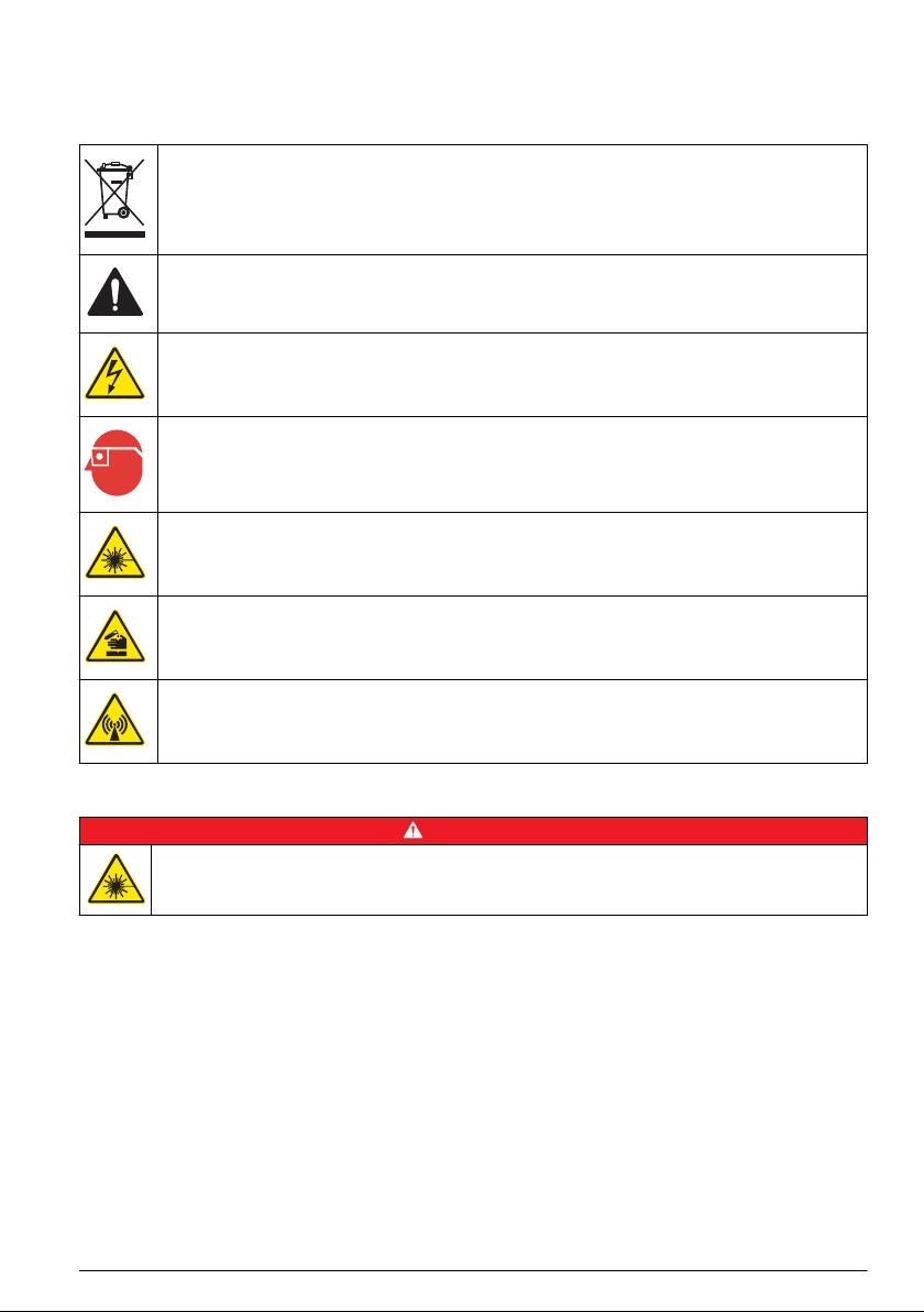
Precautionary labels
Read all labels and tags attached to the instrument. Personal injury or damage to the instrument
could occur if not observed. A symbol on the instrument is referenced in the manual with a
precautionary statement.
Electrical equipment marked with this symbol may not be disposed of in European domestic or public
disposal systems. Return old or end-of-life equipment to the manufacturer for disposal at no charge to
the user.
This symbol, if noted on the instrument, references the instruction manual for operation and/or safety
information.
This symbol indicates that a risk of electrical shock and/or electrocution exists.
This symbol indicates the need for protective eye wear.
This symbol indicates a laser device is used in the equipment.
This symbol identifies a risk of chemical harm and indicates that only individuals qualified and trained
to work with chemicals should handle chemicals or perform maintenance on chemical delivery
systems associated with the equipment.
This symbol indicates radio waves.
Class 2 laser product
Personal injury hazard. Never remove covers from the instrument. This is a laser-based instrument and
the user risks injury if exposed to the laser.
D A N G E R
English 5
Page 8
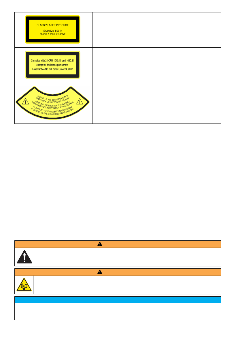
Class 2 laser product, IEC60825-1:2014, 650 nm, maximum 0.43 mW
Location: Rear of the instrument.
Conforms to U.S. regulations 21 CFR 1040.10 and 1040.11 in
accordance with Laser Notice No. 50.
Location: Rear of the instrument.
Caution—Class 2 laser radiation when the lid is open. Do not look
into the laser beam.
Location: Top of the vial compartment.
This instrument is a Class 2 Laser product. There is only visible laser radiation when the instrument
is defective and when the instrument lid is open. This product complies with EN 61010-1, "Safety
Requirements for Electrical Equipment for Measurement, Control and Laboratory Use" and with
IEC/EN 60825-1, "Safety of Laser Products" and with 21 CFR 1040.10 in accordance with Laser
Notice No. 50. Refer to the labels on the instrument that supply laser information.
RFID module
Instruments with the optional RFID module receive and transmit information and data. The RFID
module operates with a frequency of 13.56 MHz.
RFID technology is a radio application. Radio applications are subject to national conditions of
authorization. The use of instruments with the optional RFID module is currently permitted in the
regions that follow:
EU (European Union) countries, EFTA (European Free Trade Association) countries, Turkey, Serbia,
Macedonia, Australia, Canada, US, Chile, Ecuador, Venezuela, Mexico, Brazil, South Africa, India,
Singapore, Argentina, Columbia, Peru and Panama
The use of instruments with the optional RFID module outside of the above-mentioned regions can
violate national laws. The manufacturer reserves the right also to get authorization in other countries.
In case of doubt, contact the manufacturer.
Safety information for RFID modules
W A R N I N G
Multiple hazards. Do not disassemble the instrument for maintenance. If the internal components must
be cleaned or repaired, contact the manufacturer.
W A R N I N G
Electromagnetic radiation hazard. Do not use the instrument in dangerous environments.
N O T I C E
This instrument is sensitive to electromagnetic and electromechanical interference. These interferences can have
an effect on the analysis performance of this instrument. Do not put this instrument near equipment that can
cause interference.
6 English
Page 9
Obey the safety information that follows to operate the instrument in accordance with local, regional
and national requirements.
• Do not operate the instrument in hospitals and equivalent establishments or near medical
equipment, such as pace makers or hearing aids.
• Do not operate the instrument near highly flammable substances, such as fuels, highly flammable
chemicals and explosives.
• Do not operate the instrument near combustible gases, vapors or dust.
• Keep the instrument away from strong vibration or shock.
• The instrument can cause interference in immediate proximity to televisions, radios and
computers.
• The warranty does not cover improper use or wear.
FCC conformance for RFID
This instrument may contain a registered radio frequency identification device (RFID). Refer to
Table 1 for the Federal Communications Commission (FCC) registration information.
Table 1 Registration information
Parameter Value
FCC identification number (FCC ID) YUH-QR15HL
IC 9278A-QR15HL
Frequency 13.56 MHz
Certification
Canadian Radio Interference-Causing Equipment Regulation, IECS-003, Class A:
Supporting test records reside with the manufacturer.
This Class A digital apparatus meets all requirements of the Canadian Interference-Causing
Equipment Regulations.
Cet appareil numérique de classe A répond à toutes les exigences de la réglementation canadienne
sur les équipements provoquant des interférences.
FCC Part 15, Class "A" Limits
Supporting test records reside with the manufacturer. The device complies with Part 15 of the FCC
Rules. Operation is subject to the following conditions:
1. The equipment may not cause harmful interference.
2. The equipment must accept any interference received, including interference that may cause
undesired operation.
Changes or modifications to this equipment not expressly approved by the party responsible for
compliance could void the user's authority to operate the equipment. This equipment has been tested
and found to comply with the limits for a Class A digital device, pursuant to Part 15 of the FCC rules.
These limits are designed to provide reasonable protection against harmful interference when the
equipment is operated in a commercial environment. This equipment generates, uses and can
radiate radio frequency energy and, if not installed and used in accordance with the instruction
manual, may cause harmful interference to radio communications. Operation of this equipment in a
residential area is likely to cause harmful interference, in which case the user will be required to
correct the interference at their expense. The following techniques can be used to reduce
interference problems:
1. Disconnect the equipment from its power source to verify that it is or is not the source of the
interference.
2. If the equipment is connected to the same outlet as the device experiencing interference, connect
the equipment to a different outlet.
3. Move the equipment away from the device receiving the interference.
English
7
Page 10
4. Reposition the receiving antenna for the device receiving the interference.
5. Try combinations of the above.
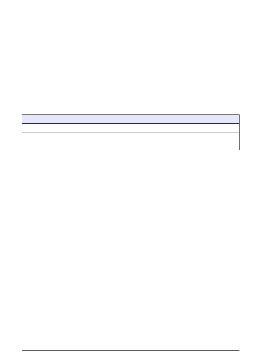
Product overview
The TU5200 turbidimeter measures low turbidity mostly in finished drinking water applications. This
laboratory instrument is factory calibrated and measures scattered light at an angle of 90° in a 360°
radius around the axis of the incident light beam. Use the touch screen to operate the instrument.
Refer to Figure 1.
An optional RFID module is available. Figure 1 shows the RFID module. The RFID module lets
process and laboratory turbidity measurements be easily compared.
Videos on how to install, operate and do maintenance and troubleshooting on the
TU5200 turbidimeter are available on the TU5 Series Turbidimeters playlist at
http://www.youtube.com/user/hachcompany.
For the accessories, refer to Replacement parts and accessories on page 34.
Figure 1 Product overview
1 Lid 6 USB port type A
2 Vial compartment 7 USB port type B
3 Display 8 Ethernet port for LAN connection
4 Power button 9 RFID module indicator (optional)
5 Power supply connection 10 USB port type A
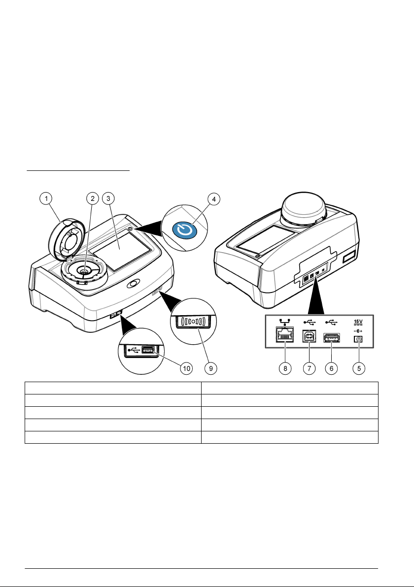
Product components
Make sure that all components have been received. Refer to Figure 2. If any items are missing or
damaged, contact the manufacturer or a sales representative immediately.
8
English
Page 11
Figure 2 Product components
1 TU5200 4 Power supply with adapters
2 StablCal kit, sealed vials with RFID (10, 20 and
600 NTU)
3 Sample vials 6 Vial stand
5 Dust cover
Installation
C A U T I O N
Multiple hazards. Only qualified personnel must conduct the tasks described in this section of the
document.
This instrument is rated for an altitude of 3100 m (10,710 ft) maximum. Use of this instrument at an
altitude higher than 3100 m can slightly increase the potential for the electrical insulation to break
down, which can result in an electric shock hazard. The manufacturer recommends that users with
concerns contact technical support.
Installation guidelines
Install the instrument:
• On a level surface
• In a clean, dry, well ventilated, temperature controlled location
• In a location with minimum vibrations that has no direct exposure to sunlight
• In a location where there is sufficient clearance around it to make connections and to do
maintenance tasks
• In a location where the power button and power cord are visible and easily accessible
Connect to external devices (optional)
The instrument has three USB 1.1 ports and one Ethernet port. Refer to Figure 1 on page 8.
English
9
Page 12
USB type A port—Connect to a printer, barcode handset scanner, USB flash drive, keyboard3 or
SIP 10 module.
USB type B port—Not used.
Ethernet port—Connect to a LAN with a shielded cable (e.g., STP, FTP, S/FTP). The maximum
length of the shielded cable is 20 m (65.6 ft). To identify if a LAN connection is necessary, refer to
Set up a LAN connection on page 16.
Note: USB cables must not be longer than 3 m (9.8 ft).
User interface and navigation
The instrument display is a touch screen. Only use a clean, dry finger tip to navigate the functions of
the touch screen. Do not use writing tips of pens or pencils or other sharp objects to make selections
on the screen or damage to the screen will occur.
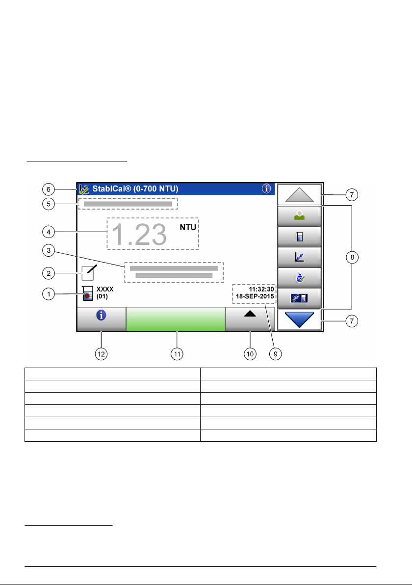
Refer to Figure 3 for an overview of the home screen.
Figure 3 Display overview
1 Sample ID and measurement number
2 User comments 8 Sidebar menu (refer to Table 2)
3 Instructions 9 Time and date
4 Turbidity value, unit and reading mode 10 Options button
5 Warning or error message 11 Read button
6 Calibration status icon and calibration curve 12 Information (help) button
3
As an alternative to the touchscreen, use a keyboard to enter text into text boxes on the display
(e.g., passwords and sample IDs).
4
The measurement number increases by one each time a measurement is completed.
4
7 UP/DOWN navigation arrows
10 English
Page 13

Icon Description
Logs in or logs out an operator. To log in, select an operator ID and then push Login. To log out,
push Logout.
Login
Sample ID
Calibration
Verification
Link2SC
Data Log
Setup
Diagnostics
Note: When an operator is logged in, the Login icon changes to the icon selected for the operator ID (e.g., fish,
butterfly or soccer ball) and the text "Login" changes to the operator ID.
Selects the sample ID.
Starts a calibration.
Starts a verification.
Compares process and laboratory measurements.
Shows the reading log, calibration log, verification log and compare log. Refer to Show the
recorded data on page 24.
Configures the instrument settings. Refer to Configure the instrument settings on page 12.
Shows the firmware information, instrument backup, instrument updates, signaling information and
factory service data.
Sets a timer.
Table 2 Sidebar menu icons
Timer
Documents
Startup
Goes to the manufacturer's website for the latest software versions and user manual when the
instrument has a LAN connection.
Shows the user manual and video(s) for the instrument.
C A U T I O N
Personal injury hazard. Never remove covers from the instrument. This is a laser-based instrument and
the user risks injury if exposed to the laser.
English 11
Page 14

C A U T I O N
Personal injury hazard. Do not look into the vial compartment when the instrument is connected to
power.
Refer to the illustrated steps that follow to connect power to the instrument and start the instrument.
When the language menu shows, select the language and then push OK. The self-check will start.
Note: To change the language after the initial startup, refer to Change the language on page 13.
Operation
Configuration
Configure the instrument settings
1. Push two times, then push Setup.
2. Select an option.
Option Description
Location Sets the location name of the instrument. The location is saved with measurements to the
Date & Time Sets the date format, the time format and the date and time. Enter the current date and
Security Enables or disables password protection for the settings and tasks in the security list.
Sound Settings Enables or disables the sound settings for individual events. Sets the sound volume for
data log.
time. Date Format—Sets the date format. Options: dd-mmm-yyyy (default), yyyy-mm-dd,
dd-mm-yyyy or mm-dd-yyyy. Time Format—Sets the time format. Options: 12 or
24 hours (default).
Security Password—Sets or changes the security (administrator) password
(10 characters maximum). Passwords are case sensitive. Security List—Sets the
security level for each setting and task in the security list.
• Off—All operators can change the setting and or do the task.
• One key—Only operators with a one-key or two-key security level can change the
setting or do the task. Refer to Add operator IDs on page 13.
• Two keys—Only operators with a two-key security level can change the setting or do
the task.
Note: The Security setting is not set to on until Close is pushed.
each event (1 to 10). To enable or disable all of the sound settings, select All and then
push Setup.
12 English
Page 15

Option Description
Network &
Peripherals
Shows the connection status of the devices that are directly connected to the instrument
and connected to the instrument by LAN (local area network).
• Printer—Local printer or network printer
• Network—LAN connection
• Controller—sc controller(s)
• PC
• USB Memory—USB flash drive
• Keyboard
Power
Management
Sets when the instrument is automatically set to sleep mode or off after a period of no
activity. Sleep Timer—Sets when the instrument is set to sleep mode. Options: OFF,
30 minutes, 1 (default), 2 or 12 hours. Power-Off Timer—Sets when the instrument is set
to off. Options: OFF, 2, 6, 12 (default) or 24 hours.
Change the language
N O T I C E
Wait a minimum of 20 seconds after the power is set to off before the power is set to on again or damage to the
instrument can occur.
To change the language after the initial startup, do the steps that follow.
1. Set the instrument to off.
2. Set the instrument to on.
3. During startup, touch the display until the language menu shows (approximately 45 seconds).
4. When the language menu shows, select the language and then push OK.
Add operator IDs
Add a unique operator ID for each person who will measure samples (30 maximum). Select an icon,
operator password and security level for each operator ID.
1. Push Login.
2. Push Options>New.
3. Enter a new operator ID (10 characters maximum), then push OK.
4. Push the LEFT and RIGHT arrows to select the icon for the operator ID (e.g., fish, butterfly or
soccer ball).
5. Push Operator Password, then enter a password for the operator ID.
Note: Passwords are case sensitive.
6. Push Security Level, then select the security level for the operator ID.
• Off—The operator cannot change the settings or do the tasks in the Security settings that have
a security level of one key or two keys.
• One key—The operator can change all the settings and do all the tasks in the Security settings
that have a security level of off or one key.
• Two keys—The operator can change all the settings and do all the tasks in the Security
settings.
Note: Before a security level can be selected, the Security setting must be set to on. Refer to Configure the
instrument settings on page 12.
7. Push OK>Close.
8. To edit an operator ID, select the operator ID and then push Options>Edit.
9. To delete an operator ID, select the operator ID and then push Options>Delete>OK.
English
13
Page 16

Configure an operator RFID tag (optional)
To use an operator RFID tag to log in to the instrument, save the applicable operator ID to an
operator RFID tag as follows:
1. Push Login.
2. Select the operator ID, then push Options>Initialize RFID Tag.
3. Enter the password for the operator ID as necessary.
4. Complete the steps that show on the display.
5. Push OK to replace the operator ID on the RFID tag with a new operator ID if applicable.
6. Push Close.
7. Put the operator RFID tag in front of the RFID module to log in.
Add sample IDs
Add a unique sample ID for each sample (100 maximum). The sample ID identifies the sample
location or other sample specific information.
As an alternative, import sample IDs from a spreadsheet file to the instrument. Refer to Import
sample IDs (optional) on page 14.
Note: When a sample bottle with a sample RFID sticker is put in front of the RFID module, the sample ID is
automatically added to the instrument and selected on the instrument.
1. Push Sample ID.
2. Push Options>New.
3. Enter a new sample ID (20 characters maximum).
4. If the sample bottle has a barcode that identifies the sample ID, read the barcode with a barcode
handset scanner that is connected to the instrument. The barcode is added to the sample ID.
5. Push OK.
6. Select an option.
Option Description
Add Date/Time Adds the data and time that the sample was collected to the sample ID (optional). The date
Add Number Adds a measurement number to the sample ID (optional). Select the first number used for
Add Color Adds a colored circle to the sample ID icon (optional). The sample ID icon shows before the
7. Push OK>Close.
8. To edit a sample ID, select the sample ID and then push Options>Edit>OK.
9. To delete a sample ID, select the sample ID and then push Options>Delete>OK.
and time entered for each sample ID show on the Sample ID menu.
the measurement number (0 to 999).
The measurement number shows in parenthesis after the sample ID on the home screen.
Refer to Figure 3 on page 10.
sample ID on the home screen. Refer to Figure 3 on page 10.
Import sample IDs (optional)
Import sample IDs from a spreadsheet file on a USB flash drive.
Note: Imported sample IDs cannot be edited.
1. On a PC, make a new spreadsheet file.
2. At the top of the first column, enter #Row Number;#Sample ID;#Date and Time for the heading.
3. Enter the information for one sample ID in each row after the heading. Make sure that there are
no spaces.
Example:
#Row Number;#Sample ID;#Date and Time
14
English
Page 17

1;Aeration;13.09.2015 10:03
2;Outlet;13.09.2015 06:30
3;Feed;13.09.2015 18:00
Note: The date of sample collection is optional.
4. Make a new folder on a USB flash drive. Give the folder the name "SampleID".
5. Save the spreadsheet file to the SampleID folder as a CSV (comma-separated value) or TXT
(text) file.
6. Connect the USB flash drive to a USB port on the instrument.
7. On the instrument, push Sample ID>Options>Import Sample ID list.
The filename of the spreadsheet file(s) in the SampleID folder shows.
8. Select the applicable spreadsheet file, then push OK.
The sample IDs are added to the instrument.
Configure the measurement settings
Select the reading mode, measurement units, data log settings, resolution and more.
1. At the main reading screen, push Options>Reading Setup.
2. Select an option.
Option Description
Reading Sets the reading mode to single, continuous or minimum mode. Default: Single. Single—
Unit Selects the measurement units that show on the display and that are recorded to the data
Data Log
Setup
Resolution Selects the number of decimal places that show on the display. Options: 0.001 (default) or
Bubble Reject Sets the bubble reject to on (default) or off. When set to on, high turbidity readings caused
Close lid to
start reading
The measurement stops when the reading is stable. Continuous—The measurement
continues until the user pushes Done. Minimum Mode—Set to on when a process and
laboratory measurement are compared and the process measurement is a lower NTU
range. Removes the effect of non-representative particles in the grab sample. Signal Avg
—The turbidity reading that shows on the display is an average of the values measured
during the time interval selected. Options: For single measurement mode, 5 to 15 seconds.
For continuous measurement mode, 5 to 90 seconds.
log. Options: NTU, FNU, TE/F, FTU, EBC, mNTU or mFNU. Default: NTU ).
Sets the data log settings. Auto Store—Measurement data is automatically recorded in the
reading log. Default: On. When not selected, push Options>Store to record the current
measurement to the reading log as necessary. Send Data Format—Sets the output format
of measurement data that is sent to external devices (CSV or XML). Default: XML. Print
Format—Sets the output format of measurement data that is sent to a printer (Quick Print
or Detailed Print (GLP)). Comments—Lets users add comments to log entries. Auto Send
—Measurement data is automatically sent to all of the devices (e.g., printer, USB flash
drive and FTP server) that are connected to the instrument after each measurement.
0.0001.
by bubbles in the sample are not shown or saved to the data log.
Enables or disables the instrument to start a measurement automatically when the lid is
closed. Default: On. A measurement is only done when there is a sample vial in the
instrument.
Set the acceptance range
Before process and laboratory measurements are compared on the instrument, set the acceptance
range for the compare results. The acceptance range is the maximum difference permitted between
the process and laboratory measurements.
1. Push LINK2SC.
2. Push Options>Compare Setup.
3. Push Acceptance Range>Unit.
English
15
Page 18

4. Select an option.
Option Description
% Sets the acceptance range to a percentage (1 to 99%).
NTU Sets the acceptance range to NTU units (0.015 to 100.00 NTU).
5. Push Value, then enter the acceptance range.
Set up a LAN connection
The manufacturer recommends that a network administrator does this task.
Set up a LAN connection at the instrument to do one or more of the tasks that follow.
• Show the manufacturer's website on the instrument.
• Compare process and laboratory measurements with Link2SC.
• Send data to a network printer that is SNMP enabled.
• Send data to a specific folder on an FTP server.
• Send data to a specific folder on a Netdrive.
• Show the readings from an sc controller(s) on the instrument.
1. Connect the Ethernet port to a LAN with a shielded cable (e.g., STP, FTP, S/FTP).
Note: The maximum permitted length of the shield cable is 20 m (65.6 ft).
2. Push two times, then push Setup.
3. Push Network & Peripherals.
4. Select Network, then push Setup.
5. Select On.
6. Push TU5200 IP.
7. To get an IP address for the instrument from a DHCP server, do the steps that follow.
a. Select Automatic.
b. Push OK two times.
The IP address shows on the TU5200 IP menu icon.
8. To manually enter an IP address for the instrument, do the steps that follow.
a. Select Fixed.
b. Push IP-Address, then enter the IP address.
c. Push Default Gateway, then enter the default gateway.
d. Push Subnet Mask, then enter the subnet mask.
e. Pusk OK two times.
The IP address shows on the TU5200 IP menu icon.
9. To compare process and laboratory measurements with Link2SC, enter the IP address for the
instrument in the sc controller as follows:
a. On the sc controller, select LINK2SC>CONFIGURE>IP ADDRESS.
b. Enter the IP address for the instrument.
Connect to an FTP server or Netdrive
Pre-requisites: Connect the instrument to a LAN. Refer to Set up a LAN connection on page 16.
Connect the instrument to a folder on an FTP server or Netdrive to send data to that folder.
1. Push two times, then push Setup.
2. Push Network & Peripherals.
3. Select Network, then push Setup.
16
English
Page 19

4. Push Network Server.
5. To connect to a folder on an FTP server, do the steps that follow.
a. Select FTP.
b. Push FTP Server.
6. To connect to a folder on a Netdrive, do the steps that follow.
a. Select Netdrive.
b. Push Netdrive Setup.
7. Select an option.
Option Description
IP-Address Selects the IP address of the FTP server or Netdrive. Push IP-Address and enter the IP
Server Name Selects the server name of the FTP server or Netdrive. Push Server Name and enter the
address of the FTP server or Netdrive.
server name of the FTP server or Netdrive.
8. Push Data Folder, then enter the name of the target folder that is on the FTP server or Netdrive.
9. Push User, then enter a user name that has read/write permissions for the target folder.
10. Push Password, then enter the password for the user name.
11. Push OK three times.
Connect to a network printer
Pre-requisites: Connect the instrument to a LAN. Refer to Set up a LAN connection on page 16.
Connect a network printer to the instrument to send data to a remote (network) printer. Only network
printers that are SNMP enabled and in the same sub network are found by the instrument.
1. Push two times, then push Setup.
2. Push Network & Peripherals.
3. Select Printer, then push Setup.
4. Push Network Printer, then select On.
5. Push Printer IP, then select Automatic.
6. When the printer list shows, select a printer and then push OK.
7. Push Resolution, then select the printer resolution (100 or 150 dpi).
8. Push Paper, then select the paper size. Options: Letter, Legal, Executive or A4.
9. Push OK two times.
Connect to an sc controller
Pre-requisites: Connect the instrument to a LAN. Refer to Set up a LAN connection on page 16.
Connect the instrument to one or more sc controllers that have a LAN connection5 to do the tasks
that follow.
• Show the current readings from an sc controller(s).
• Show previous readings from an sc controller(s) for the day, week or month in graph format.
• Show the current reading for one parameter from an sc controller in the sidebar menu.
Note: This task is not necessary to compare process and laboratory measurements with Link2SC.
1. Push two times, then push Setup.
2. Push Network & Peripherals.
3. Select Controller, then push Setup.
5
Refer to the sc controller documentation to set up a LAN connection.
English 17
Page 20

4. Push Add.
5. To enter the IP address of the sc controller, do the steps that follow.
a. Select IP-Address.
b. Push IP-Address, then enter the IP address of the sc controller.
6. To enter the host name of the sc controller, do the steps that follow.
a. Select Hostname.
b. Push Hostname, then enter the server name of the sc controller.
7. Push Password, then enter the password for the sc controller.
8. Push OK>CLOSE>CLOSE.
9. Select the channels (parameters) that show on the instrument as follows:
a. Push Link2SC.
b. Push Process Monitoring>Add.
c. Select the channel, then push OK.
The current reading and the previous readings for the channel show in graph format.
10. Do step 9 again to show more channels on the display as necessary.
11. To change the time interval that shows on the graph, push the graph and select Day, Week or
Month.
12. To show the current reading for one of the channels in the sidebar menu, select the channel and
then push the minimize icon at the top of the screen.
The current reading for the channel shows in the sidebar menu after the Verification icon.
Measurement
Sample collection
• Collect samples in clean glass or plastic bottles with tight-fitting caps.
• Rinse the container a minimum of three times with the sample.
• When collecting a sample from a water tap in a distribution system or treatment plant, turn the
water on for at least five minutes, then collect the sample. Do not adjust the flow because this can
add particles.
• When collecting a sample from a body of water (e.g., a stream or storage tank), collect at least one
liter (1 quart) and fully mix before taking an aliquot for measurement. If the quality of the sample
source is not constant, collect samples at many locations at different depths as necessary. Then,
mix the samples together to prepare one sample for measurement.
• Fill the container. Let the container overflow with the sample and then immediately put the cap on
the sample container so that there is no headspace (air) above the sample.
• Write the sample information on the container.
• Start analysis as soon as possible to prevent temperature changes, bacteria growth and settling.
Prevent vial contamination
N O T I C E
Do not to touch or scratch the glass of the sample vial. Contamination or scratches on the glass can cause
measurement errors.
The glass must stay clean and have no scratches. Use a no-lint cloth to remove dirt, fingerprints or
particles from the glass. Replace the sample vial when the glass has scratches.
Refer to Figure 4 to identify where not to touch the sample vial. Always keep the sample vials in the
vial stand to prevent contamination on the bottom of the vial.
18
English
Page 21

Figure 4 Sample vial overview
1 Measurement surface—Do not touch.
Prepare a sample vial
C A U T I O N
Chemical exposure hazard. Dispose of chemicals and wastes in accordance with local, regional and
national regulations.
N O T I C E
Always put a cap on the sample vial to prevent spills in the vial compartment.
Refer to the illustrated steps that follow to prepare a sample vial for measurement. Measure the
sample immediately.
Note: If there is contamination in the sample vial after it is rinsed with the sample, clean the sample vial. Refer to
Clean a sample vial on page 29.
English
19
Page 22

Put the vial in the instrument
C A U T I O N
Personal injury hazard. Never remove covers from the instrument. This is a laser-based instrument and
the user risks injury if exposed to the laser.
C A U T I O N
Personal injury hazard. Do not look into the vial compartment when the instrument is connected to
power.
N O T I C E
Keep the lid closed to keep contamination out of the vial compartment.
1. Log in to the instrument as follows:
• Put an operator RFID tag in front of the RFID module or
• Push Login. Select the applicable operator ID, then push Select.
2. Select the sample ID as follows:
• Put the sample RFID sticker on the sample bottle in front of the RFID module or
• Push Sample ID. Select the applicable sample ID, then push Select.
Note: To add sample IDs to the instrument, refer to Add sample IDs on page 14.
3. Clean the sample vial with a no-lint cloth to remove contamination.
4. Dry the external surfaces of the vial with a no-lint cloth. Make sure to dry the bottom of the vial.
5. Put the sample vial in the vial compartment. Refer to the illustrated steps that follow.
20
English
Page 23

Measure the sample
1. Push Read if a measurement does not start automatically when the lid is closed.
2. When the measurement is complete, push Options>Store to record the measurement to the
reading log as necessary.
Note: If the Auto Save setting is set to on, "Data Stored" shows on the display and the measurement is
automatically recorded to the reading log.
3. To show the recorded measurements, push Options>Reading Log. Refer to Show the recorded
data on page 24 for more options.
4. To send the measurement data to external devices that are connected to the instrument, push
Options>Send Data. Refer to Show the recorded data on page 24 for more options.
Note: If the Auto Send settings is set to on, the measurement data is automatically sent to the external
device(s) that is connected to the instrument.
Compare process and laboratory measurements
Compare process and laboratory measurements with RFID or Link2SC. Make sure that the process
and lab instrument are calibrated with the same number of calibration points and with the same
standards. Make sure that the calibrations are not expired.
Collect a grab sample
Collect a 100-mL sample (minimum) from the sample outlet tubing of the process instrument. Collect
the sample in a clean glass bottle with a tight-fitting cap. Do not collect samples directly into a sample
vial.
1. Rinse the glass bottle a minimum of three times with water from the sample outlet tubing of the
process instrument. Let the bottle overflow with the sample.
2. Collect a 100-mL sample (minimum) in the glass bottle from the sample outlet tubing of the
process instrument.
3. Put the cap on the sample bottle.
4. Analyze the grab sample immediately with the laboratory instrument to prevent settling, bacteria
growth and temperature changes.
Compare measurements with RFID
When the process instrument and laboratory instrument have the optional RFID module, compare
process and laboratory measurements with RFID.
Items to collect:
• TU5300 sc or TU5400 sc with the optional RFID module
• TU5200 with the optional RFID module
• TU5200 sample vials
English
21
Page 24

• Glass sample bottle with a sample RFID sticker
• Operator RFID tag (optional)
1. At the process instrument, put the operator RFID tag (if available) near the RFID module.
2. Put a sample RFID sticker on the sample bottle.
3. Collect a grab sample. Refer to Collect a grab sample on page 21.
4. At the process instrument, put the RFID sticker that is on the sample bottle near the RFID
module.
The instrument gives a sound signal. The status indicator light changes to blue.
The turbidity reading, operator ID (if available), location of the process instrument and the date
and time are recorded on the RFID sticker.
5. Move the grab sample bottle to the laboratory instrument.
6. On the TU5200, push Options>Reading Setup.
7. Push Bubble Reject, then set bubble reject to on.
8. If the grab sample is 1 NTU or less, push Reading>Minimum Mode, then select 60 seconds.
Note: In minimum mode, readings are done continuously for 60 seconds when a measurement is done. The
smallest reading within 60 seconds is saved to the data log.
9. At the laboratory instrument, put the operator RFID tag (if available) near the RFID module to log
in. Refer to Figure 1 on page 8 for the location of the RFID module.
10. Put the RFID sticker that is on the sample bottle near the RFID module.
The instrument gives a sound signal. The turbidity reading from the process instrument shows on
the display.
11. Prepare a grab sample vial. Refer to Prepare a sample vial on page 19.
12. Measure the turbidity of the grab sample with the laboratory instrument. Refer to the
TU5200 documentation.
If the difference between the process and laboratory measurements is not more than the selected
acceptance range, "Measurement values match." shows on the display. Refer to Set the
acceptance range on page 15 to select the acceptance range.
If "Measurement values do not match." shows on the display, click the link to show the
troubleshooting steps.
13. To show the compare log, push Options>Compare Log. Refer to the TU5200 documentation for
more options.
14. To send the verification data to external devices that are connected to the instrument, push
Options>Send Data. Refer to the TU5200 documentation for more options.
Compare measurements with Link2SC
When the process instrument and laboratory instrument do not have the optional RFID module,
compare the process and laboratory measurements with Link2SC.
Items to collect:
• TU5300 sc or TU5400 sc
• TU5200
• TU5200 sample vials
• SD card6 (or a LAN connection at the SC controller7 and the laboratory instrument8)
• USB adapter for the SD card (if used)
6
Refer to the SC controller documentation for the SD card requirements.
7
Refer to the SC controller documentation to set up a LAN connection at the SC controller.
8
Refer to the TU5200 documentation to set up a LAN connection at the laboratory instrument.
22 English
Page 25

1. Collect a grab sample. Refer to Collect a grab sample on page 21.
2. If the SC controller and laboratory instrument do not have a LAN connection, install the SD card
in the SC controller. Refer to the SC controller documentation to install the SD card.
3. At the SC controller, make a Link2SC job file as follows:
a. Push menu.
b. Select LINK2SC>CREATE A NEW JOB>TU5x00 sc.
The SC controller makes a Link2SC job file. The turbidity reading, operator ID (if available),
location of the process instrument and the date and time are recorded to the job file.
In addition, the temperature, calibration settings, bubble reject setting, vial clarity and
desiccant cartridge life are recorded to the Link2SC job file.
4. Push OK, then YES.
5. Select JOB>LAB.
The Link2SC job file is saved to the SD card (if available) or sent to the laboratory instrument
(when the SC controller and laboratory instrument have a LAN connection).
To see the Link2SC job files on the SD card, select JOBS FROM CARD.
6. If the SC controller and laboratory instrument do not have a LAN connection, complete the steps
that follow.
a. Remove the SD card from the SC controller.
b. At the laboratory instrument, put the SD card in the USB adapter. Then put the USB adapter
in a USB port type A on the laboratory instrument.
7. Move the grab sample bottle to the laboratory instrument.
8. On the TU5200, push Options>Reading Setup.
9. Push Bubble Reject, then set bubble reject to on.
10. If the grab sample is 1 NTU or less, push Reading>Minimum Mode, then select 60 seconds.
Note: In minimum mode, readings are done continuously for 60 seconds when a measurement is done. The
smallest reading within 60 seconds is saved to the data log.
11. At the laboratory instrument, push the LINK2SC to show the job list.
12. Select the latest Link2SC job file.
The turbidity measurement from the process instrument shows on the right side of the display.
13. Prepare a grab sample vial. Refer to Prepare a sample vial on page 19.
14. Measure the turbidity of the grab sample with the laboratory instrument. Refer to the
TU5200 documentation.
If the difference between the process and laboratory measurements is not more than the selected
acceptance range, "Measurement values match." shows on the display. Refer to Configure the
Link2SC settings on page 24 to select the acceptance range.
If "Measurement values do not match." shows on the display, click the link to show the
troubleshooting steps.
15. To show the compare log, push Options>Compare Log. Refer to the TU5200 documentation for
more options.
16. To send the verification data to external devices that are connected to the instrument, push
Options>Send Data. Refer to the TU5200 documentation for more options.
English
23
Page 26

Configure the Link2SC settings
Select the acceptance range permitted when process and laboratory measurements are compared
with Link2SC.
1. Push menu.
2. Select SENSOR SETUP>TU5x00 sc>LINK2SC.
3. Select an option.
Option Description
ACCEPT. UNIT Sets the units used to compare the process and laboratory measurements. Options: %,
ACCEPT. RANGE Sets the maximum difference permitted between the process and laboratory
NTU or LAB. Select LAB when the acceptance range is supplied by the laboratory
instrument.
measurements. Options: 1 to 50% (default: 10%). This option only shows when
ACCEPT. UNIT is set to % or NTU.
Show the recorded data
All the recorded data is kept in the data log. The data log is divided into four logs:
• Reading log—Shows the recorded measurements.
• Calibration log—Shows the calibration history.
• Verification log—Shows the verification history.
• Compare log—Shows the recorded comparisons of process and laboratory measurements.
1. Push Data Log and select the applicable log to show.
2. To show the details of a log entry, select the log entry and then push View Details.
Note: To add a comment to the log entry, push the comments icon.
3. To only show the log entries recorded during a time interval or with a specific operator ID or
sample ID, do the steps that follow.
a. Push Filter, then select On.
b. Select an option.
Option Description
Time Interval Selects the time interval.
Operator ID Selects the operator ID.
Sample ID Selects the sample ID. This option only shows when Reading Log or Compare Log is
4. To send log data to a device (e.g., printer or USB flash drive), delete a log entry or show a
compare log or reading log entries in a graph, do the steps that follow.
a. Push Options.
selected.
24
English
Page 27

b. Select an option.
Option Description
Delete Removes one of the items that follow.
• The selected log entry
• The log entries for a time interval
• The log entries with a specific operator ID
• The log entries with a specific sample ID
• All the entries in the selected log
9
Send
Data
View
Graph
Sends one of the items that follow to all the devices that are directly connected to the
instrument (e.g., printer or USB flash drive) and connected to the instrument by LAN (network
printer or FTP server).
• The selected log entry
• The log entries for a time interval
• The log entries with a specific operator ID
• The log entries with a specific sample ID
• All the entries in the selected log
Shows the reading log entries that have the same sample ID in a graph. This option only
shows when Compare Log or Reading Log is selected.
To add the log entries for another sample ID to the graph, push Options>Add Data. Select a
sample ID to add to the graph.
To show the details of a data point, touch a data point on the display or push the LEFT and
RIGHT arrows to select a data point.
Data points—Selects the symbol used for the data points. Control Limit—Sets the
minimum value and maximum value of the readings that show on the graph.
9
Show the instrument information
1. Push Diagnostics.
2. Select an option.
Option Description
Instrument
Information
Signals Shows the status of the lid, sample vial, turbidity, condensation and fouling. If a USB
Instrument Backup Store—Saves a backup of all the instrument settings and log files to a USB flash drive.
Instrument Update Installs an instrument update on the instrument. Put a USB flash drive with the
Service Time Shows the date entered for the last service date and for the next service date. When
Factory Service For factory use only.
Shows the instrument model, version, serial number, location name and MAC address.
flash drive or PC is connected to the instrument, push the icon to send data to the USB
flash drive or PC as necessary.
Restore—Copies the instrument settings, reading log files and compare log files from
a USB flash drive to the instrument. Overwrites all the instrument settings.
instrument update in a USB port.
set to on, a service reminder shows on the display when service is due.
9
This option only shows when Reading Log or Compare Log is selected.
English 25
Page 28

Calibration
W A R N I N G
Chemical exposure hazard. Obey laboratory safety procedures and wear all of the personal protective
equipment appropriate to the chemicals that are handled. Refer to the current safety data sheets
(MSDS/SDS) for safety protocols.
When the instrument is used for US EPA regulatory reporting, calibrations must be done according to
US EPA guidance documents and methodologies. Contact local regulating authorities for additional
compliance regulations.
The instrument is factory calibrated and the laser light source is stable. The manufacturer
recommends that a calibration verification be done periodically to make sure that the system
operates as intended. The manufacturer recommends calibration after repairs or comprehensive
maintenance work.
Configure the calibration settings
Select the calibration curve, calibration interval and more.
1. Push Calibration.
2. Push Options>Calibration Setup.
3. Select an option.
Option Description
Calibration
Curve
Verify after Cal. Sets the instrument to start a verification immediately after the instrument is calibrated.
Calibration
Reminder
Reset to
Factory
Calibration
Selects the type of standard and the calibration curve (range). StablCal RapidCal
(0–40 NTU)—1-point calibration (20 NTU) with StablCal. StablCal (0–700 NTU)—2-point
calibration (20 NTU and 600 NTU) with StablCal. Formazin RapidCal (0–40 NTU)—2point calibration (20 NTU and dilution water) with Formazin. Formazin (0–700 NTU)—3point calibration (20 NTU, 600 NTU and dilution water) with Formazin. Degrees
(0–100 mg/L)—3-point calibration (20 mg/L, 100 mg/L and dilution water) with kaolin.
SDVB (0–700 NTU)—3-point calibration (20 NTU, 600 NTU and dilution water) with
spherical slyrene divinylbenzene. Custom Calibration—1- to 6-point calibration (0.02 to
700 NTU) with StablCal or Formazin. The user selects the number of calibration points
and the value of each calibration point.
When set to on, the verification standard is measured immediately after a calibration is
done. Default: ON.
Sets the time interval between calibrations. When a calibration is due, the display will
show a reminder and a question mark on the calibration icon at the top of the display.
Options: Off (default), 1 day, 7 days, 30 days or 90 days. When a calibration is done, the
calibration time is set to zero.
Sets the calibration settings to the factory defaults.
Calibrate the instrument
When the instrument is used for US EPA regulatory reporting, calibrations must be done according to
US EPA guidance documents and methodologies. Contact local regulating authorities for additional
compliance regulations.
The instrument is factory calibrated.
1. Log in to the instrument as follows:
• Put an operator RFID tag in front of the RFID module or
26
English
Page 29

• Push Login. Select the applicable operator ID, then push Select.
2. For RFID vials, put the vial in front of the RFID module. Refer to Figure 5.
A calibration is started. The instrument receives the value, the lot number, the expiration date and
the Certificate of Analysis information from the RFID vial.
3. For non-RFID vials, push Calibration.
4. Clean the vial with a no-lint cloth to remove contamination.
Keep contamination off the glass. Refer to Prevent vial contamination on page 18.
5. Dry the external surfaces of the vial with a no-lint cloth. Make sure to dry the bottom of the vial.
6. Carefully invert at least three times. Refer to Figure 6.
Note: For StablCal vials, refer to the documentation supplied with the StablCal vial to prepare the vials for use.
7. Put the vial in the vial compartment.
8. Push Start.
9. Confirm the value shown or enter the exact turbidity value of the standard. Push Read.
10. When the measurement is complete, remove the vial.
11. Do steps 2 to 10 again until all the standard values that show on the display are measured.
12. Push Store to complete the calibration and record the results to the calibration log.
13. To show the calibration log, push Options>Calibration Log. Refer to Show the recorded data
on page 24 for more options.
14. To send the calibration data to external devices that are connected to the instrument, push
Options> Send Data. Refer to Show the recorded data on page 24 for more options.
Figure 5 Put the RFID vial in front of the RFID module
Figure 6 Invert the vial
English 27
Page 30

Verification
Configure the verification settings
Select the acceptance range and measurement units for calibration verification and more.
1. Push Verification.
2. Push Options>Verification Setup.
3. Select an option.
Option Description
Standard Value Measures the verification standard. The results are recorded to the instrument. For the
Verify after Cal. Sets the instrument to start a verification immediately after the instrument is calibrated.
Acceptance
Range
Verification
Reminder
Do a calibration verification
Do a calibration verification to make sure that the instrument is still calibrated as necessary.
1. Log in to the instrument as follows:
• Put an operator RFID tag in front of the RFID module or
• Push Login. Select the applicable operator ID, then push Select.
2. Push Verification.
3. Clean the verification standard vial with a no-lint cloth to remove contamination.
Keep contamination off the glass. Refer to Prevent vial contamination on page 18.
4. Dry the external surfaces of the vial with a no-lint cloth. Make sure to dry the bottom of the vial.
5. Carefully invert the vial three times. Refer to Figure 6 on page 27.
6. Put the vial in the vial compartment.
7. Push Start.
8. Confirm the value shown or enter the exact turbidity value of the standard. Push Read.
9. When the measurement is complete, remove the vial.
The verification is recorded to the verification log.
10. To show the verification log, push Options>Verification Log. Refer to Show the recorded data
on page 24 for more options.
11. To send the verification data to external devices that are connected to the instrument, push
Options>Send Data. Refer to Show the recorded data on page 24 for more options.
best results, measure the verification standard immediately after calibration.
When set to on, the verification standard is measured immediately after a calibration is
done. Default: ON.
Sets the maximum difference permitted between the recorded value of the verification
standard and the measured value of the verification standard during verification. Unit—
Sets the acceptance range for verification to a percentage (1 to 99%) or an NTU value
(0.015 to 100.00 NTU). Options: % or NTU (or mNTU).
Sets the time interval between calibration verifications. The display will show a reminder
when a verification is due. Options: OFF(default), 1 day, 7 days, 30 days or 90 days.
When a verification is done, the verification time is set to zero.
Maintenance
Multiple hazards. Only qualified personnel must conduct the tasks described in this section of the
document.
28 English
C A U T I O N
Page 31

C A U T I O N
Chemical exposure hazard. Obey laboratory safety procedures and wear all of the personal protective
equipment appropriate to the chemicals that are handled. Refer to the current safety data sheets
(MSDS/SDS) for safety protocols.
C A U T I O N
Personal injury hazard. Never remove covers from the instrument. This is a laser-based instrument and
the user risks injury if exposed to the laser.
N O T I C E
Do not disassemble the instrument for maintenance. If the internal components must be cleaned or repaired,
contact the manufacturer.
Clean spills
C A U T I O N
Chemical exposure hazard. Dispose of chemicals and wastes in accordance with local, regional and
national regulations.
1. Obey all facility safety protocols for spill control.
2. Discard the waste according to applicable regulations.
Clean the instrument
Clean the exterior of the instrument with a moist cloth, and then wipe the instrument dry.
Clean a sample vial
C A U T I O N
Chemical exposure hazard. Obey laboratory safety procedures and wear all of the personal protective
equipment appropriate to the chemicals that are handled. Refer to the current safety data sheets
(MSDS/SDS) for safety protocols.
Clean the sample vial when there is contamination in the sample vial after the sample vial is rinsed.
Items to collect:
• Hydrochloric acid (concentration 10%)
• Laboratory cleaning detergent for glass (concentration 0.1%)
• Distilled or deonized water
• Dilution water
• Vial wiper (optional)
• No-lint cloth
1. Put the exterior and interior surfaces of the sample vial and the cap in 10% hydrochloric acid for
15 minutes.
2. Clean the exterior and interior surfaces of the sample vial and the cap with laboratory cleaning
detergent for glass (concentration 0.1%).
English
29
Page 32

3. Fully rinse the sample vial three times with distilled or deionized water.
Note: If the sample vial is used to measure low range turbidity samples or dilution water, rinse with dilution
water (not distilled or deionized water).
4. For the best results, clean the sample vial with the optional vial wiper. Then fully rinse the sample
vial again. Refer to Figure 7.
5. Dry the external surfaces of the sample cell with a soft, no-lint cloth. Do not let the sample vial air
dry.
6. For storage, fill the sample vial with distilled or demineralized water.
Note: If the sample vial is used to measure low range turbidity samples or dilution water, fill the sample vial with
dilution water (not distilled or deionized water).
7. Immediately put the cap on the sample vial to keep the interior of the sample vial wet.
Figure 7 Clean the vial with the vial wiper (optional)
Clean the vial compartment
Clean the vial compartment only when the compartment has contamination. Make sure that the tool
to clean the vial compartment has a soft surface and does not damage the instrument. Table 3
shows the options on how to clean the vial compartment.
Table 3 Cleaning options
Contaminant Options
Dust Vial compartment wiper, micro fiber cloth, lint-free cloth
Liquid, oil Cloth, water and cleaning agent
Troubleshooting
Message Solution
Startup
The self-check stopped.
Clean the vial compartment.
The self-check stopped.
Close the lid.
30 English
The vial compartment is dirty. Set the power to off. Clean the vial compartment.
Refer to Clean the vial compartment on page 30. Set the power to on. If the self
check is not successful, contact technical support.
Close the lid. Push Close.
Page 33

Message Solution
The self-check stopped.
Hardware error.
Error [x]
The self-check stopped.
Set the power to off, wait 20 seconds and then set the power to on again. If the
self check is not successful, record the error number and contact technical
support.
Contact technical support.
The light source is not
stable.
The last update was not
completed.
Connect the USB flash drive to the instrument to install the instrument update files.
Complete the steps that show on the display.
Update the instrument.
Next calibration is due! Calibrate the instrument. Refer to Calibrate the instrument on page 26.
Note: The calibration reminder is set to on. Refer to Configure the calibration settings
on page 26.
Next service is due! Contact technical support.
Note: The service reminder is set to on. Refer to Show the instrument information on page 25.
Next verification is due! Do a calibration verification. Refer to Do a calibration verification on page 28.
Note: The verification reminder is set to on. Refer to Configure the verification settings
on page 28.
Reading
Clean the vial. Wipe the sample vial with a no-lint cloth to remove contamination and
condensation from the glass.
Hardware error / instrument
error
The calibration range is
exceeded.
Set the power to off, wait 20 seconds and then set the power to on again. If the
problem continues, contact technical support.
The measured turbidity is more than the calibration range of the instrument. Select
a calibration curve for the full measurement range. Refer to Configure the
calibration settings on page 26.
The measurement range is
The measured turbidity is more than the measurement range of the instrument.
exceeded.
Calibration/Verification
Instrument error Examine the standards. Start the calibration or verification again.
If calibration (or verification) is not successful, contact technical support.
The standard is not stable. Use the correct calibration standards. Invert the standard until no bubbles or large
particles show.
The standard value is out of
the measurement range.
The standard value is too
low.
Use the correct calibration standards. Invert the standards. Make sure to measure
the standards in ascending order.
The wrong calibration standard is in the vial compartment. Make sure that the
standard has not expired.
Put the correct calibration standard in the vial compartment. Make sure to invert
the standard.
The standard value is too
high.
The wrong calibration standard is in the vial compartment. Make sure that the
standard has not expired.
Put the correct calibration standard in the vial compartment.
Verification failed. Examine the verification standard. Calibrate the instrument. Refer to Calibrate the
instrument on page 26.
If verification is not successful, push Calibration>Options>Calibration
Setup>Reset to Factory Calibration>OK.
English 31
Page 34

Message Solution
Compare process and laboratory measurements
Measurement values are not
the same.
Instrument update
Copy from USB Memory
failed
Instrument update file is
missing
Instrument update file is
corrupt
Update script file is corrupt
Not enough memory to
update the instrument
USB memory is not
connected.
Read/Write to USB flash drive
Cannot write to USB
memory
Cannot read from USB
memory
Restore backup
No instrument backup is
available.
Not able to restore the
backup
Security
Invalid password Enter the correct password. If the password is lost, contact technical support.
Send data
Connect a receiving device. Examine the device connections. Set the Auto Send setting to off. Refer to
Click the link to get troubleshooting information. Some typical solutions are as
follows:
• Clean the vial. Refer to Clean a sample vial on page 29.
• Calibrate the instrument with the same calibration curve as the process
instrument. Use the same standards to calibrate the process and laboratory
instruments. Make sure that the standards have not expired.
• Set the Bubble Reject setting to on. Refer to Configure the measurement
settings on page 15.
• There was too much time between the process measurement and laboratory
measurement.
• Clean the vial compartment.
Remove large files from the USB flash drive that use too much space. Start the
instrument update procedure again.
Remove the instrument update files from the USB flash drive. Save the instrument
update files again to the USB flash drive.
Connect the USB flash drive to the instrument. Start the instrument update
procedure again.
Remove the instrument update files from the USB flash drive. Save the instrument
update files again to the USB flash drive.
Connect the USB flash drive to the instrument. Start the instrument update
procedure again.
Contact technical support.
Connect a USB flash drive to the instrument. Make sure that the file system
"FAT32" is installed on the USB flash drive.
Set the power to off, wait 20 seconds and then set the power to on again. Connect
the USB flash drive. Start the instrument update procedure again.
Connect a USB flash drive to the instrument. Make sure that the file system
"FAT32" is installed on the USB flash drive.
Set the power to off, wait 20 seconds and then set the power to on again. Look for
remaining space on the USB flash drive.
Set the power to off, wait 20 seconds and then set the power to on again. Connect
the USB flash drive to the instrument.
Connect a USB flash drive to the instrument. Make sure that the file system
"FAT32" is installed on the USB flash drive.
Set the power to off, wait 20 seconds and then set the power to on again. Connect
the USB flash drive. Start the instrument update procedure again.
Configure the measurement settings on page 15.
32 English
Page 35

Message Solution
Add sample IDs from list
No valid data found No sample ID file was found on the USB flash drive.
Not able to read sampling
date.
The instrument cannot read
the Sample ID
Problem/Error: Incorrect
date
Possible cause: The wrong
date format.
The sample ID list full. Data
has not been added
Documents/Videos
The document does not
show on the display.
Not enough memory to store
the document.
Cannot delete the
document.
Cannot store the document. Contact technical support.
Cannot open the manual. Make sure that the document format is PDF.
The video format is not
supported.
The video does not play. The video file is corrupt.
Ethernet/LAN connection
Network authentication
failed
LAN Connection failed
Automatic retrieval of the
local IP address failed!
Setting IP-address failed!
Setting subnet-mask failed!
Setting default gateway
failed!
Mounting network drive
failed!
FTP connection failed!
Verify network configuration
Files did not save to the
network share.
No connection to the web
server.
Make sure that the date and time format is dd.mm.yyyy hh:mm.
Examine the text strings. Refer to Import sample IDs (optional) on page 14.
Make sure that the date and time format is dd.mm.yyyy hh:mm.
Remove the sample IDs that are not used. Add a new sample ID.
Make sure that the document is saved as a PDF.
Delete other documents, then add the document again.
Contact technical support.
Make sure that the video format is AVI (Codec XVID) with a resolution of 640 x
480 pixels. Make sure that the video size is not more than 10 Mb.
Enter the correct username and password. Make sure that the network settings
are correctly configured.
There is no connection to the DHCP server. Contact the network administrator.
If the DHCP server is not enabled, manually enter an IP address for the
instrument.
Contact the network administrator. If necessary, contact technical support.
Make sure that the correct permissions are set to the network share directory.
Try to connect the instrument to a LAN again later. Make sure that the instrument
is connected to the network.
English 33
Page 36

Message Solution
RFID
Standard expired. Continue? Use standards that are not expired.
Primary standard is write
protected.
Measured value is out of
nominal value range.
No act. value on RFID tag.
Read standard?
Measured with different
calibration. Read standard?
Measured with different
instrument type. Read
standard?
The verification standard value cannot be recorded on a calibration standard.
The measured value is not within range for this standard. The 10 NTU standard
range is 5 to 15 NTU. The < 0.1 NTU glass verification rod range is 0 to 0.1 NTU.
Use the correct standard. Make sure that the standard is not expired. Measure the
standard again.
Measure the verification standard first on an instrument that was recently
calibrated.
The verification standard was measured for a different calibration curve (e.g.,
StablCal, Formazin, SDVB, degrees or custom).
The verification standard was measured on a different type of instrument (e.g.,
different lasers).
Remove air bubbles from the sample
Air bubbles can cause unstable readings. Use a degassing method to remove air or other gases from
the sample before measurement even if no bubbles are seen.
The methods typically used for degassing are:
• Let the sample stand for several minutes
• Apply a vacuum
• Use the sample degassing kit
• Use an ultrasonic bath
Let the samples stand for several minutes, then gently invert two or three times before measurement.
In some cases, more than one method may be necessary to remove bubbles (e.g., the use of heat
with an ultrasonic bath may be necessary in some severe conditions). Use care with these methods
as sample turbidity can be changed if these methods are not used correctly.
Condensation
If condensation collects on the sample vial during measurement, let the sample become slightly
warmer before measurement. Keep the sample at room temperature or partially put the sample vial
into a warm water bath for a short time.
Note: A temperature increase can change the sample turbidity. Measure the sample before the temperature
increases when possible.
Replacement parts and accessories
W A R N I N G
Personal injury hazard. Use of non-approved parts may cause personal injury, damage to the
instrument or equipment malfunction. The replacement parts in this section are approved by the
manufacturer.
Note: Product and Article numbers may vary for some selling regions. Contact the appropriate distributor or refer to
the company website for contact information.
34
English
Page 37

Recommended standards
Description Quantity Item no.
Verification standard, < 0.1 NTU, glass verification rod (solid
secondary standard)
StablCal kit, sealed vials with RFID, includes:
10, 20 and 600 NTU vials
StablCal 20-NTU sealed vial with RFID each LZY837
StablCal 600-NTU sealed vial with RFID each LZY838
StablCal kit, sealed vials without RFID, includes:
10, 20 and 600 NTU vials
StablCal 20-NTU sealed vial without RFID each LZY899
StablCal 600-NTU sealed vial without RFID each LZY900
each LZY901
each LZY835
each LZY898
Replacement parts
Description Quantity Item no.
Cover, USB port type A 1 LZV881
Dust cover 1 LZV947
Lid 1 LZV968
Power supply with adapters, 100 to 240 V, 50/60 Hz 1 LZV798
Sample vials with caps 2 LZV946
Vial stand 1 LZV952
Accessories
Description Quantity Item no.
Micro fiber cloth, vial cleaning 1 LZY945
RFID tags, operator 2/pkg LZQ066
RFID stickers, sample bottle, black
Vial wiper 1 LZY903
Vial compartment wiper 1 LZY910
Sample degassing kit 1 4397510
10
Other colors are available.
10
3/pkg LZQ067
English 35
Page 38

36 English
Page 39

Page 40

HACH COMPANY World Headquarters
P.O. Box 389, Loveland, CO 80539-0389 U.S.A.
Tel. (970) 669-3050
(800) 227-4224 (U.S.A. only)
Fax (970) 669-2932
orders@hach.com
www.hach.com
©
Hach Company/Hach Lange GmbH, 2015–2017.
HACH LANGE GMBH
Willstätterstraße 11
D-40549 Düsseldorf, Germany
Tel. +49 (0) 2 11 52 88-320
Fax +49 (0) 2 11 52 88-210
info-de@hach.com
www.de.hach.com
All rights reserved.
HACH LANGE Sàrl
6, route de Compois
1222 Vésenaz
SWITZERLAND
Tel. +41 22 594 6400
Fax +41 22 594 6499
 Loading...