

Page 1

DOC022.97.80535
TL2350
07/2016, Edition 2
Manuel d'utilisation de base
Manual básico del usuario
Manual Básico do Usuário
Basic User Manual
基本用户手册
基本取扱説明書
기본 사용 설명서
คู่มือผู้ใช้เบื้องต้น
Page 2

English..............................................................................................................................3
Français......................................................................................................................... 24
Español.......................................................................................................................... 47
Português...................................................................................................................... 69
中文................................................................................................................................. 92
日本語........................................................................................................................... 111
한글............................................................................................................................... 132
ไทย.................................................................................................................................. 153
2
Page 3

Table of contents
Specifications on page 3 Startup on page 10
General information on page 4 Operation on page 11
Installation on page 8 Maintenance on page 20
User interface and navigation on page 9 Troubleshooting on page 21
Specifications
Specifications are subject to change without notice.
Specification Details
Measurement method Nephelometric
Regulatory Meets EPA Method 180.1
ASTM D7315 - Standard Test Method for Determination of Turbidity Above 1 Turbidity
Unit (TU) in Static Mode
ASTM D6655 - Standard Test Method for Determination of Turbidity Below 5 NTU in
Static Mode
Dimensions (W x D x H) 39.5 x 30.5 x 15.3 cm (15.6 x 12.0 x 6.02 in.)
Weight 3.0 kg (6.6 lb)
Enclosure IP30; indoor use only
Protection Class External power supply: Protection Class I; instrument: Protection Class II
Pollution degree 2
Installation category External power supply: Category II; instrument: Category I
Power requirements Instrument: 12 VDC, 3.4 A; power supply: 100–240 VAC, 50/60 Hz
Operating temperature 0 to 40 °C (32 to 104 °F)
Storage temperature –20 to 60 °C (–4 to 140 °F)
Humidity 5 to 95% relative humidity, non-condensing
Display 17.8 mm (7 in.) color touch screen
Light source Tungsten filament lamp
Measurement units NTU, EBC, Abs (absorbance), %T (% transmittance) and mg/L (degree)
Range NTU (Ratio on): 0–10,000 auto decimal
NTU (Ratio off): 0–40
EBC (Ratio on): 0–2450 auto decimal
EBC (Ratio off): 0–9.8
Absorbance1 (auto range): 0–1.0
Transmittance1 (%): 1.0–100
Degree (mg/L): 1–100
1
A filter assembly is necessary for absorbance or transmittance measurements
English 3
Page 4

Specification Details
Accuracy2, 3,
Resolution Turbidity: 0.001 NTU/EBC
Repeatability ±1% of reading or 0.01 NTU, whichever is greater (under reference conditions)
Response time Signal averaging off: 6.8 seconds
Stabilization time Ratio on: 30 minutes after start-up
Reading modes Single, continuous, Rapidly Settling Turbidity™, signal averaging on or off, ratio on or
Communication USB
Interface 2 USB-A ports for USB flash drive, external printer, keyboard and barcode scanner
Datalog Maximum 2000 total logs, includes reading log, verification log and calibration log
Air purge Dry nitrogen or instrument grade air (ANSI MC 11.1, 1975)
Sample cells Round cells 95 x 25 mm (3.74 x 1 in.) borosilicate glass with rubber-lined screw caps
Sample requirements 25 mm sample cell: 20 mL minimum
Certification CE, KC, RCM
Warranty 1 year (EU: 2 years)
4
Ratio on: ±2% of reading plus 0.01 NTU from 0–1000 NTU, ±5% of reading from
1000–4000 NTU, ±10% of reading from 4000–10,000 NTU
Ratio off: ±2% of reading plus 0.01 NTU from 0–40 NTU
Absorbance: ±0.01 Abs from 0–0.5 Abs at 455 nm, ±2% Abs from 0.5–1 Abs at 455 nm
Transmittance: 2% T from 10–100% T at 455 nm
Absorbance: 0.001 Abs
Transmittance: 0.1% T
Signal averaging on: 14 seconds (when 10 measurements are used to calculate the
average)
Ratio off: 60 minutes after start-up
off
0.1 scfm at 69 kPa (10 psig); 138 kPa (20 psig) maximum
Hose barb connection for 1/8-inch tubing
Note: Smaller sample cells (less than 25 mm) can be used when a cell adapter is used.
0 to 70 °C (32 to 158 °F)
General information
In no event will the manufacturer be liable for direct, indirect, special, incidental or consequential
damages resulting from any defect or omission in this manual. The manufacturer reserves the right to
make changes in this manual and the products it describes at any time, without notice or obligation.
Revised editions are found on the manufacturer’s website.
Additional information
Additional information is available on the manufacturer's website.
2
Turbidity specifications identified using USEPA filter assembly, recently prepared formazin
standard and matched 25-mm sample cells.
3
Intermittent electromagnetic radiation of 3 volts/meter or greater may cause slight accuracy
shifts.
4
Reference conditions: 23 ± 2 °C, 50 (± 10)% RH noncondensing, 100–240 VAC, 50/60 Hz
4 English
Page 5

Safety information
N O T I C E
The manufacturer is not responsible for any damages due to misapplication or misuse of this product including,
without limitation, direct, incidental and consequential damages, and disclaims such damages to the full extent
permitted under applicable law. The user is solely responsible to identify critical application risks and install
appropriate mechanisms to protect processes during a possible equipment malfunction.
Please read this entire manual before unpacking, setting up or operating this equipment. Pay
attention to all danger and caution statements. Failure to do so could result in serious injury to the
operator or damage to the equipment.
Make sure that the protection provided by this equipment is not impaired. Do not use or install this
equipment in any manner other than that specified in this manual.
Use of hazard information
Indicates a potentially or imminently hazardous situation which, if not avoided, will result in death or serious injury.
Indicates a potentially or imminently hazardous situation which, if not avoided, could result in death or serious
injury.
Indicates a potentially hazardous situation that may result in minor or moderate injury.
Indicates a situation which, if not avoided, may cause damage to the instrument. Information that requires special
emphasis.
Precautionary labels
Read all labels and tags attached to the instrument. Personal injury or damage to the instrument
could occur if not observed. A symbol on the instrument is referenced in the manual with a
precautionary statement.
This symbol, if noted on the instrument, references the instruction manual for operation and/or safety
information.
D A N G E R
W A R N I N G
C A U T I O N
N O T I C E
Electrical equipment marked with this symbol may not be disposed of in European domestic or public
disposal systems. Return old or end-of-life equipment to the manufacturer for disposal at no charge to
the user.
Certification
EN 55011/CISPR 11 Notification Warning
This is a Class A product. In a domestic environment this product may cause radio interference in
which case the user may be required to take adequate measures.
Canadian Radio Interference-Causing Equipment Regulation, IECS-003, Class A:
Supporting test records reside with the manufacturer.
This Class A digital apparatus meets all requirements of the Canadian Interference-Causing
Equipment Regulations.
Cet appareil numérique de classe A répond à toutes les exigences de la réglementation canadienne
sur les équipements provoquant des interférences.
FCC Part 15, Class "A" Limits
English
5
Page 6

Supporting test records reside with the manufacturer. The device complies with Part 15 of the FCC
Rules. Operation is subject to the following conditions:
1. The equipment may not cause harmful interference.
2. The equipment must accept any interference received, including interference that may cause
undesired operation.
Changes or modifications to this equipment not expressly approved by the party responsible for
compliance could void the user's authority to operate the equipment. This equipment has been tested
and found to comply with the limits for a Class A digital device, pursuant to Part 15 of the FCC rules.
These limits are designed to provide reasonable protection against harmful interference when the
equipment is operated in a commercial environment. This equipment generates, uses and can
radiate radio frequency energy and, if not installed and used in accordance with the instruction
manual, may cause harmful interference to radio communications. Operation of this equipment in a
residential area is likely to cause harmful interference, in which case the user will be required to
correct the interference at their expense. The following techniques can be used to reduce
interference problems:
1. Disconnect the equipment from its power source to verify that it is or is not the source of the
interference.
2. If the equipment is connected to the same outlet as the device experiencing interference, connect
the equipment to a different outlet.
3. Move the equipment away from the device receiving the interference.
4. Reposition the receiving antenna for the device receiving the interference.
5. Try combinations of the above.
Korean certification
업무용을 위한 EMC 등급 A 장치에 대한
사용자 지침
사용자안내문
A 급 기기 ( 업무용 방송통신기자재 )
이 기기는 업무용 (A 급 ) 전자파적합기기로서 판매자 또는 사용자는 이 점을 주의하시기 바라며 , 가정
외의 지역에서 사용하는 것을 목적으로 합니다.
Product overview
C A U T I O N
Fire hazard. This product is not designed for use with flammable liquids.
The TL2350 laboratory turbidimeter measures the scattered light from water samples to determine
the turbidity value of the samples. In the ratio-on mode, the instrument uses multiple detectors at
different angles to correct for interferences and to increase the measurement range. In the ratio-off
mode, the instrument uses one detector at a 90-degree angle from the light source. The user can
calibrate the instrument and verify the calibration at regular intervals.
The user interface uses a touch screen display. A printer, USB flash drive or keyboard can connect
to the USB ports. Refer to Figure 1. The real-time clock with battery puts a time-date stamp on all of
the data that is transmitted or recorded (i.e., reading log, calibration log and verification log).
6
English
Page 7

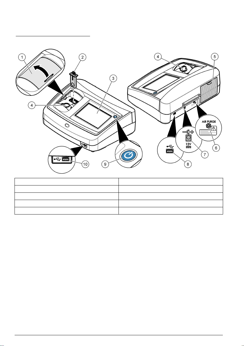
Figure 1 Product overview
1 Sample compartment lid 6 Air purge
2 EPA filter 7 Power connection
3 Touch screen display 8 USB port
4 Sample cell holder 9 Power button
5 Lamp cover 10 USB port
Product components
Make sure that all components have been received. Refer to Figure 2. If any items are missing or
damaged, contact the manufacturer or a sales representative immediately.
English
7
Page 8

Figure 2 Instrument components
1 Silicone oil 6 Gelex® secondary turbidity standardization kit
2 Oiling cloth 7 StablCal® Calibration kit
3 USEPA filter assembly 8 Power supply
4 TL2350 turbidimeter 9 Power cord
5 1-inch sample cells (30 mL) with caps (6x) 10 Dust cover
Installation
C A U T I O N
Multiple hazards. Only qualified personnel must conduct the tasks described in this section of the
document.
This instrument is rated for an altitude of 3100 m (10,710 ft) maximum. Use of this instrument at an
altitude higher than 3100 m can slightly increase the potential for the electrical insulation to break
down, which can result in an electric shock hazard. The manufacturer recommends that users with
concerns contact technical support.
Installation guidelines
Install the instrument:
• On a level surface
• In a clean, dry, well ventilated, temperature controlled location
• In a location with minimum vibrations that has no direct exposure to sunlight
• In a location where there is sufficient clearance around it to make connections and to do
maintenance tasks
• In a location where the power button and power cord are visible and easily accessible
Connect to external devices (optional)
Use the USB ports to connect the instrument to a printer, barcode handset scanner, USB flash drive
or keyboard. Refer to Figure 1 on page 7. The maximum length of a connected USB cable is 3 m
(9.8 ft). As an alternative to the touchscreen, use a keyboard to enter text into text boxes on the
display (e.g., passwords and sample IDs).
8
English
Page 9

User interface and navigation
The instrument display is a touch screen. Only use a clean, dry finger tip to navigate the functions of
the touch screen. Do not use writing tips of pens or pencils or other sharp objects to make selections
on the screen or damage to the screen will occur.
Refer to Figure 3 for an overview of the home screen.
Figure 3 Display overview
1 Sample ID and measurement number
2 User comments 8 Sidebar menu (refer to Table 1)
3 Instructions 9 Time and date
4 Turbidity value, unit and reading mode 10 Options button
5 Warning or error message 11 Read button
6 Calibration status icon and calibration curve 12 Home/Instrument information button
5
7 UP/DOWN navigation arrows
Table 1 Sidebar menu icons
Icon Description
Logs in or logs out an operator. To log in, select an operator ID and then push Login. To log out,
push Logout.
Login
Sample ID
Calibration
5
The measurement number increases by one each time a measurement is completed.
Note: When an operator is logged in, the Login icon changes to the icon selected for the operator ID (e.g., fish,
butterfly or soccer ball) and the text "Login" changes to the operator ID.
Selects the sample ID.
Starts a calibration.
English 9
Page 10
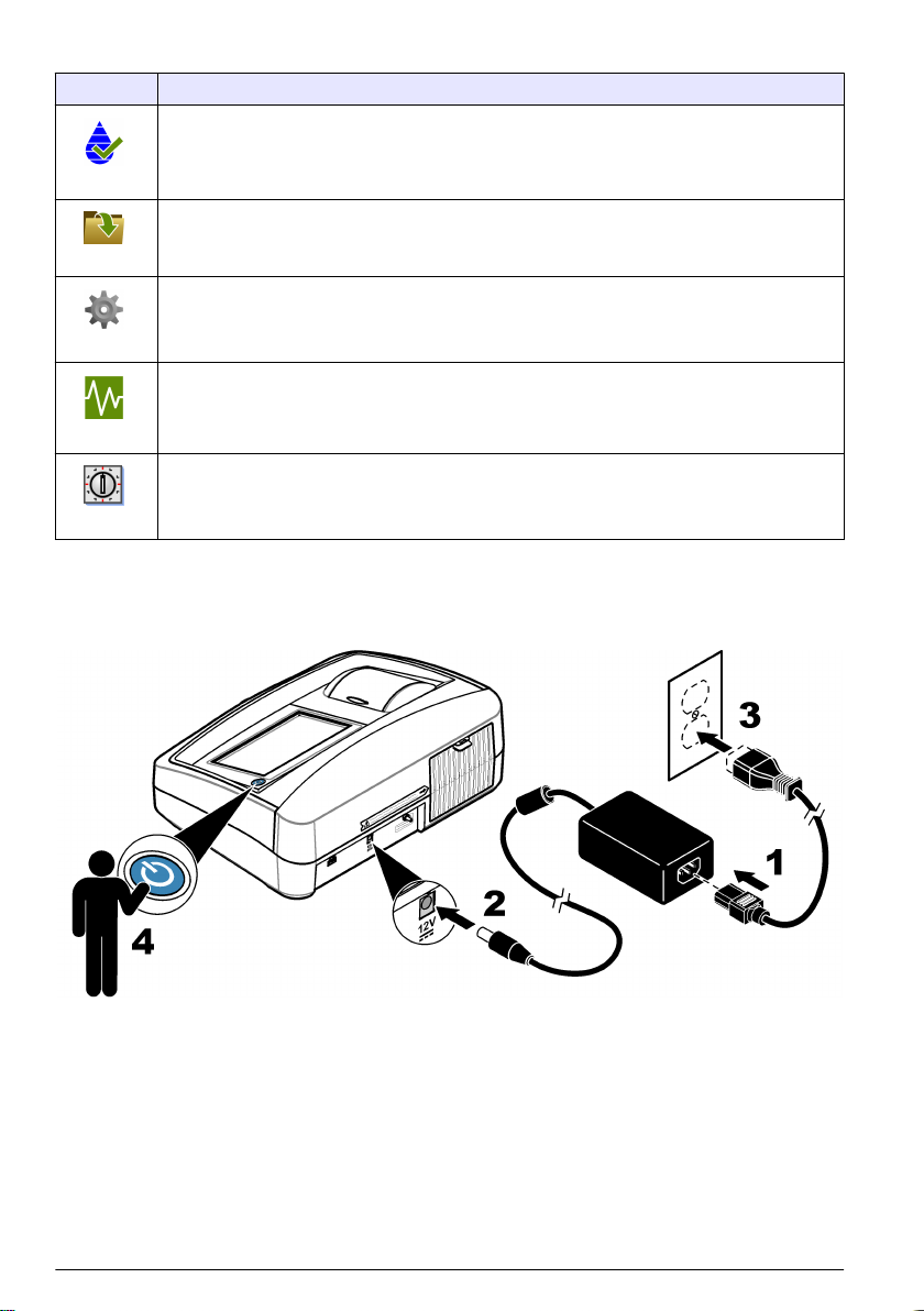
Table 1 Sidebar menu icons (continued)
Icon Description
Starts a verification.
Verification
Shows the reading log, calibration log and verification log. Refer to Show the recorded data
on page 19.
Data Log
Configures the instrument settings. Refer to Configure the instrument settings on page 11.
Setup
Shows the firmware information, instrument backup, instrument updates, signaling information and
factory service data.
Diagnostics
Sets a timer.
Timer
Startup
Refer to the illustrated steps that follow to supply power to the instrument and start the instrument.
The self-check will start.
10 English
Page 11

Operation
Configure the instrument settings
1. Push , then push Setup.
2. Select an option.
Option Description
Location Sets the location name of the instrument. The location is sent with measurements to the
Date & Time Sets the date format, the time format and the date and time. Enter the current date and
Security Enables or disables password protection for the settings and tasks in the security list.
Sound Settings Enables or disables the sound settings for individual events. To enable or disable all of
Peripherals Shows the connection status of attached devices such as a printer, USB memory (flash
Power
Management
USB drive. The location is not saved to the data log.
time. Date Format—Sets the date format. Options: dd-mm-yyyy (default), yyyy-mm-dd,
dd-mm-yyyy or mm-dd-yyyy. Time Format—Sets the time format. Options: 12 or
24 hours (default).
Security Password—Sets or changes the security (administrator) password
(10 characters maximum). Passwords are case sensitive. Security List—Sets the
security level for each setting and task in the security list.
• Off—All operators can change the setting or do the task.
• One key—Only operators with a one-key or two-key security level can change the
setting or do the task. Refer to Add operator IDs on page 12.
• Two keys—Only operators with a two-key security level can change the setting or do
the task.
Note: The Security setting is not set to on until Close is pushed.
the sound settings, select All and then push Setup.
drive) or keyboard.
Sets when the instrument is automatically set to sleep mode or off after a period of no
activity. Sleep Timer—Sets when the instrument is set to sleep mode. Options: OFF,
30 minutes, 1 (default), 2 or 12 hours.
Configure the measurement settings
Select the reading mode, measurement units, data log settings and more.
1. At the main reading screen, push Options>Reading Setup.
2. Select an option.
Option Description
Reading
Mode
Unit Selects the measurement units that show on the display and that are recorded to the data log.
Sets the reading mode to single, continuous or RST mode. Single (default)—The
measurement stops when the reading is stable. Continuous—The measurement continues
until the user pushes Done. RST—The Rapidly Settling Turbidity (RST) mode calculates and
continuously updates the turbidity reading of the sample to a confidence of 95%, based on the
accumulated trend of the real time measured values. The RST mode is best used on samples
that settle rapidly and continuously change in value. The reading is based on a correctly
prepared sample that is homogeneous at the beginning of the reading. It is best applied to
samples that are greater than 20 NTU. The sample must be mixed thoroughly by inversion
immediately before inserting it into the instrument. Signal Avg—The turbidity reading that
shows on the display is an average of the values measured during the time interval selected.
Options: For single measurement mode, 5 to 15 seconds. For continuous measurement mode,
5 to 90 seconds.
Options: NTU (default), EBC, Abs or %T.
English 11
Page 12

Option Description
Ratio Sets the ratio mode to on (default) or off. When set to off, an indicator shows on the reading
Bubble
Reject
Data Log
Setup
window.
Note: The ratio off mode is only valid for turbidity measurements that are less than 40 NTU.
Sets the bubble reject to on (default) or off. When set to on, high turbidity readings caused by
bubbles in the sample are not shown or saved to the data log.
Sets the data log settings. Auto Store—Measurement data is automatically recorded in the
reading log. Default: On. If Auto Store is off, push Options>Store to manually save a reading in
the data log. Send Data Format—Sets the output format of measurement data that is sent to
external devices (CSV, XML or BMP). Default: XML. Print Format—Sets the output format of
measurement data that is sent to a printer (Quick Print or Detailed Print (GLP)). Comments—
Lets users add comments to log entries. Auto Send—Measurement data is automatically sent
to all of the devices (e.g., printer and USB flash drive) that are connected to the instrument after
each measurement. Options: Off, new file or continue file: off—do not auto send data, new file—
send data and save it in a new file, continue file—send data and save all data in one file.
Add operator IDs
Add a unique operator ID for each person who will measure samples (30 maximum). Select an icon,
operator password and security level for each operator ID.
1. Push Login.
2. Push Options>New.
3. Enter a new operator ID (20 characters maximum), then push OK.
4. Push the LEFT and RIGHT arrows to select the icon for the operator ID (e.g., fish, butterfly or
soccer ball).
5. Push Operator Password, then enter a password for the operator ID.
Note: Passwords are case sensitive.
6. Push Security Level, then select the security level for the operator ID.
• Off—The operator cannot change the settings or do the tasks in the Security settings that have
a security level of one key or two keys.
• One key—The operator can change all the settings and do all the tasks in the Security settings
that have a security level of off or one key.
• Two keys—The operator can change all the settings and do all the tasks in the Security
settings.
Note: Before a security level can be selected, the Security setting must be set to on. Refer to Configure the
instrument settings on page 11.
7. Push OK>Close.
8. To edit an operator ID, select the operator ID and then push Options>Edit.
9. To delete an operator ID, select the operator ID and then push Options>Delete>OK.
Add sample IDs
Add a unique sample ID for each sample (1000 maximum). The sample ID identifies the sample
location or other sample specific information.
As an alternative, import sample IDs from a spreadsheet file to the instrument. Refer to the expanded
user manual on the manufacturer's website to import sample IDs.
1. Push Sample ID.
2. Push Options>New.
3. Enter a new sample ID (20 characters maximum).
4. Push OK.
12
English
Page 13

5. Select an option.
Option Description
Add Date/Time Adds the date and time that the sample was collected to the sample ID (optional). The date
Add Number Adds a measurement number to the sample ID (optional). Select the first number used for
Add Color Adds a colored circle to the sample ID icon (optional). The sample ID icon shows before the
and time entered for each sample ID show on the Sample ID menu.
the measurement number (0 to 999).
The measurement number shows in parenthesis after the sample ID on the home screen.
Refer to User interface and navigation on page 9.
sample ID on the home screen. Refer to User interface and navigation on page 9.
6. Push OK>Close.
7. To edit a sample ID, select the sample ID and then push Options>Edit>OK.
8. To delete a sample ID, select the sample ID and then push Options>Delete>OK.
Note: To delete all sample ID's, select the sample ID and then push Options>Delete All Sample IDs>OK.
Calibrate the turbidimeter with StablCal Standards
Calibrate the turbidimeter before it is used for the first time using the StablCal sealed vial standards
provided.
Calibrate the turbidimeter at least every 3 months or as specified by the regulating authority when
data is used for USEPA reporting.
The instrument is ready for calibration 60 minutes after start-up. Keep the instrument on 24 hours a
day if the instrument is used regularly.
Note: Unknown results may occur if standards other than the recommended calibration points are used. The
recommended calibration points (< 0.1, 20, 200, 1000, 4000 and 7500 NTU) provide the best calibration accuracy.
Use of standards other than StablCal, or user-prepared formazin, may result in less accurate calibrations. The
manufacturer cannot guarantee the performance of the instrument if calibrated with co-polymer
styrenedivinylbenzene beads or other suspensions.
Calibration notes
• Make sure that the instrument is in the same ambient conditions as where it is used.
• Make sure that the standards are at the same ambient temperature as the instrument before use.
• Use only the provided silicone oil. This silicone oil has the same refractive index as the vial glass
and masks minor glass differences and scratches.
• Store the oiling cloth in a plastic storage bag to keep the cloth clean.
• If power is lost during calibration, the new calibration data is lost and the last calibration data is
used.
• In Calibration mode, automatic range and signal averaging on are selected. When calibration is
completed, all operational modes go back to the last settings.
• All nephelometric (turbidity units of measure) calibrations are done at the same time.
• Ratio-on and Ratio-off calibration data is measured and recorded at the same time.
• Clean the USEPA filter assembly before doing a primary calibration, or at least every 3 months
(which is the USEPA-recommended primary calibration interval).
Configure the calibration settings
Change the calibration settings as necessary before the instrument is calibrated. The instrument
must be calibrated when the calibration curve is changed.
1. Push Calibration.
2. Push Options>Calibration Setup.
English
13
Page 14

3. Select the calibration curve range and type of calibration standard.
Option Description
StablCal RapidCal
(0–40 NTU)
StablCal (0–10000
NTU)
Formazin RapidCal
(0–40 NTU)
Formazin (0–10000
NTU)
Degrees (0–100 mg/L) Full-range calibration (20 mg/L, 100 mg/L and dilution water) with kaolin.
SDVB (0–10000 NTU) Full-range calibration (20 NTU, 200 NTU, 1000 NTU, 4000 NTU, 7500 NTU and
EU Pharm (0–30 NTU) Full-range calibration (<0.1 NTU, 3 NTU, 6 NTU, 18 NTU, 30 NTU).
Custom Calibration The user can enter a custom calibration for turbidity. The user selects the number
Calibration with 20-NTU StablCal standard (default).
Note: The dark current in the instrument is used as the zero point of the calibration
curve. The calibration curve is linear from 0-40 NTU, thus low turbidity
measurements are very accurate.
Full-range calibration (<0.1 NTU, 20 NTU, 200 NTU, 1000 NTU, 4000 NTU,
7500 NTU) with StablCal.
Calibration with 20-NTU formazin standard.
Note: The dark current in the instrument is used as the zero point of the calibration
curve. The calibration curve is linear from 0-40 NTU, thus low turbidity
measurements are very accurate.
Full-range calibration (20 NTU, 200 NTU, 1000 NTU, 4000 NTU, 7500 NTU and
dilution water) with formazin.
dilution water) with spherical styrene divinylbenzene.
of calibration standards and the value of each calibration standard. Use a custom
calibration when smaller sample cells are used with a sample cell adapter.
4. Select the remaining calibration options.
Option Description
Verify after Cal. Sets the instrument to start a verification immediately after the instrument is calibrated.
Calibration
Reminder
Reset to Factory
Calibration
When set to on, the verification standard is measured immediately after a calibration is
done. Default: ON. The value of the verification standard shows on the display as the
last standard during calibration.
Sets the time interval between calibrations. When a calibration is due, the display will
show a reminder and a question mark on the calibration icon at the top of the display.
Options: Off (default), 1 day, 7 days, 30 days or 90 days. When a calibration is done,
the calibration time is set to zero.
Sets the calibration settings to the factory defaults.
Prepare the StablCal standards
When received and at intervals:
1. Clean the exterior surface of the StablCal vials with laboratory glass cleaning detergent.
2. Rinse the vials with distilled or deionized water.
3. Dry the vials with a lint-free cloth.
Note: Never shake or invert the < 0.1 NTU standard. If the standard has been mixed or shaken, do not move the
vial for 15 minutes or more before using.
Note: Do not remove the caps from the sealed vials.
Make sure that the StablCal standards are at ambient instrument temperature before use (and no
greater than 40 °C (104 °F)).
Invert the standards (except < 0.1 NTU) before use. Refer to the user instructions that are supplied
with the StablCal standards.
14
English
Page 15

StablCal calibration procedure
1. Push Login and
select the applicable
Operator ID. If login is
not necessary, go to
step 3.
5. Hold the tab of the
USEPA filter assembly
so that the arrows point
toward the front of the
instrument. Push the
filter assembly fully in
the housing.
2. Push Login and
enter the password.
Push OK.
6. Push Calibration.
The standard values for
the selected calibration
curve (and verification
standard, if Verify after
Cal is on) show on the
display. To select a
different calibration
curve, refer to
Configure the
calibration settings
on page 13.
3. Remove the filter
assembly.
7. Get the StablCal
standard that shows on
the display. Clean the
vial with a soft, lint-free
cloth to remove water
spots and fingerprints.
4. Clean the lens of the
USEPA filter assembly.
Refer to Clean the filter
assembly on page 20.
8. Apply a small drop
of silicone oil from the
top to the bottom of the
vial.
9. Use the oiling cloth
to apply the oil equally
to the surface of the
vial. Remove most of
the oil. Make sure that
the vial is almost dry.
10. Carefully and
slowly invert the vial to
fully mix the standard
(do not invert the
<0.1 NTU vial). Be
careful not to add air
bubbles.
11. Put the vial in the
sample cell holder with
the triangle on the vial
aligned with the
reference mark on the
sample cell holder.
Push the lid closed until
a click is heard.
12. Push Read. Wait
1 minute for the
instrument to complete
the measurement.
English 15
Page 16

13. Open the lid and
remove the vial from
the sample cell holder.
14. Do steps 7–13 for
the other StablCal vials
(from lowest to highest
NTU standard). When
complete, the
measured values are
shown.
15. If Verify after Cal is
set to on, the value of
the verification standard
shows. Push Read to
measure the verification
standard.
16. Push Store to save
the new calibration
data.
Verification procedure
Use the verification procedure to measure the same Gelex or StablCal vial at regular intervals to
determine if the reading stays within the acceptance range. Use the Verification Setup menu to set a
reminder for the verification.
1. Push Login and
select the applicable
Operator ID. If login is
not necessary, go to
step 3.
5. Apply a small drop
of silicone oil from the
top to the bottom of the
vial.
16 English
2. Push Login and
enter the password.
Push OK.
6. Use the oiling cloth
to apply the oil equally
to the surface of the
vial. Remove most of
the oil. Make sure that
the vial is almost dry.
3. Push Verification.
The verification
standard value is
shown. Push
Options>Verification
Setup to change the
value of the verification
standard.
7. Put the vial in the
sample cell holder with
the triangle on the vial
aligned with the
reference mark on the
sample cell holder.
Push the lid closed until
a click is heard.
4. Clean the Gelex
vials with a soft, lint-free
cloth to remove water
spots and fingerprints.
8. Push Read. The
value and pass or fail
status shows. The data
is automatically stored
in the instrument.
Page 17

Turbidity measurement
For accurate turbidity readings use clean sample cells and remove air bubbles.
Measurement notes
Proper measurement techniques are important in minimizing the effects of instrument variation, stray
light and air bubbles. For accurate and repeatable measurements:
Instrument
• Make sure that the instrument is on a level, stationary surface that is free of vibration during the
measurement.
• The USEPA filter assembly is required for turbidity measurements reported for United States
Environmental Protection Agency (USEPA), National Primary Drinking Water Regulations
(NPDWR) or National Pollutant Discharge Elimination System (NPDES) permits.
• Turn the instrument on 30 minutes (Ratio on) or 60 minutes (Ratio off) before measurement. Keep
the instrument on 24 hours a day if the instrument is used regularly.
• Always close the sample compartment lid during measurement, calibration and verification.
• Remove the sample cell from the instrument and turn off the instrument if the instrument is stored
for an extended time period (more than a month).
• Keep the sample compartment lid closed to keep dust and dirt out.
Sample cells
• Always cap the sample cell to prevent spillage of the sample into the instrument.
• Always use clean sample cells in good condition. Dirty, scratched or damaged cells can result in
readings that are not accurate.
• Make sure that cold samples do not “fog” the sample cell.
• Store sample cells filled with distilled or deionized water and cap tightly.
• For the best accuracy, use a single sample cell for every measurement or a flow cell.
Note: As an alternative, matched sample cells may be used for measurements but do not provide as good of
accuracy or precision as a single indexed sample cell or flow cell. When using matched sample cells, align the
orientation mark on the sample cell with the reference mark on the sample cell holder.
Measurement
• Measure samples immediately to prevent temperature changes and settling. Before a
measurement is taken, always make sure that the sample is homogeneous throughout.
• Avoid sample dilution when possible.
• Avoid instrument operation in direct sunlight.
English
17
Page 18

Turbidity measurement procedure
To include an operator ID and sample ID with the measurement data, refer to Add sample IDs
on page 12 and Add operator IDs on page 12.
1. Push Login and
select the applicable
Operator ID. If login is
not necessary, go to
step 3.
5. Clean the sample
cells with a soft, lint-free
cloth to remove water
spots and fingerprints.
2. Push Login and
enter the password.
Push OK.
6. Apply a small bead
of silicone oil from the
top to the bottom of the
sample cells.
3. Push Sample ID.
Select the applicable
sample ID, then push
Select. The selected
sample ID shows on the
display.
7. Use the oiling cloth
provided to apply the oil
equally to the surface of
the sample cells.
Remove the excess oil.
Make sure that the
sample cells are almost
dry.
4. Rinse a clean,
empty sample cell two
times with the solution
to be measured and
drain to waste. Fill to
the line (about 30 mL)
with sample and
immediately put the cap
on the sample cell.
8. Gently and slowly
invert the sample cell to
fully mix the sample. Be
careful not to add air
bubbles.
9. Put the sample cell
in the sample cell
holder with the triangle
on the sample cell
aligned with the
reference mark on the
sample cell holder.
Push the lid closed until
a click is heard.
18 English
10. Push Read (or
Done if in continuous
mode). Wait for the
instrument to read the
sample.
Note: If auto store is
off, push Options >
Store to save the data.
Page 19

Data management
Show the recorded data
All the recorded data is kept in the data log. There are three types of data logs:
• Reading log—Shows the recorded measurements.
• Calibration log—Shows the calibration history.
• Verification log—Shows the verification history.
1. Push Data Log and select the applicable data log.
2. To show the details of a log entry, select the log entry and then push View Details.
Note: To add a comment to the log entry, push the comments icon.
3. To show only some of the data, push Filter, then select On. The Filter Settings window opens.
4. Select an option.
Option Description
Time Interval Selects only the data that was stored during a specific time interval.
Operator ID Selects only the data that was stored with a specific operator ID.
Sample ID Selects only the data from the Reading Log that was stored with a specific sample ID.
Send data to a connected device
The instrument can send data to a USB memory device or printer. For best results, use only USB
2.0 memory devices. The instrument makes a logger folder on the device and saves the data as
a .bmp, .csv or .xml file.
Use only the printers that are shown in the expanded version of this manual.
1. Connect a USB memory device or cable to a USB port on the instrument.
2. Connect the other end of the cable to the printer, if applicable.
3. Go to Setup>Peripherals. The connection status shows Connected. If the status shows Not
Connected, make sure to use the recommended devices.
4. Push Data Log and select the applicable log.
5. To send only some of the data, use the filter settings or select a single data point. Refer to Show
the recorded data on page 19.
6. Push Options>Send Data Log. Select single data point, filtered data or all data. Push OK.
The instrument sends the selected data to the connected devices.
Delete data from the data log
The instrument automatically deletes the oldest data record when the data log is full. The user can
also delete data manually. Make sure to save the data to an external device, then delete the data in
the data log.
1. Push Data Log and select the applicable log.
2. To delete only some of the data, use the filter settings. Refer to Show the recorded data
on page 19.
3. To delete the data, push Options>Delete Data. Select single data point, filtered data or all data.
Push OK.
The instrument deletes the selected data from the data log.
English
19
Page 20

Maintenance
C A U T I O N
Multiple hazards. Only qualified personnel must conduct the tasks described in this section of the
document.
Clean spills
C A U T I O N
Chemical exposure hazard. Dispose of chemicals and wastes in accordance with local, regional and
national regulations.
1. Obey all facility safety protocols for spill control.
2. Discard the waste according to applicable regulations.
Clean the instrument
Clean the exterior of the instrument with a moist cloth, and then wipe the instrument dry.
Clean the filter assembly
Note: Be careful not to push the lens out of the filter assembly.
1. Clean both sides of the lens of the filter assembly with glass cleaner, lens cleaner or isopropyl
alcohol, and a cotton-tipped swab or lens tissue.
2. Inspect the filter glass for scratches or other damage.
3. If a cloudy circle is seen around the edge of the filter, the filter material is delaminating. Replace
the filter assembly.
Replace the lamp
C A U T I O N
Wear protective eye wear when the lamp is turned on and the lamp cover is removed.
C A U T I O N
Burn hazard. The lamp must be cool before removal from the instrument.
Notes:
• Replace the lamp with the same size, style and electrical rating.
• Do not touch the lamp as oil from skin will damage the lamp. Clean the lamp with alcohol as
necessary.
• Either lamp lead can be put in either terminal block position.
• Turn the instrument on 30 minutes (Ratio on) or 60 minutes (Ratio off) before measurement or
calibration.
• Calibrate the instrument after the lamp is replaced.
To replace the lamp, refer to the documentation that is supplied with the lamp.
20
English
Page 21

Instrument utilities
1. Push Home to see the instrument model, version, serial number and location name.
2. Push Diagnostics.
3. Select an option.
Option Description
Factory Service For factory/service use only.
Instrument Backup Store—Saves a backup of all the instrument settings and log files to a USB flash drive.
Instrument Update Installs an instrument update on the instrument from a USB flash drive.
Service Time Shows the date entered for the last service date and for the next service date. When
Restore—Copies the instrument settings and log files from a USB flash drive to the
instrument. Overwrites all the instrument settings.
set to on, a service reminder shows on the display when service is due.
Troubleshooting
Message Solution
Startup
The self-check stopped.
Hardware error.
Next calibration is due! Calibrate the instrument. Refer to Calibrate the turbidimeter with StablCal
Next service is due! Contact technical support.
Next verification is due! Do a calibration verification. Refer to the expanded user manual on the
Reading
Hardware error / instrument
error
The calibration range is
exceeded.
The measurement range is
exceeded.
Calibration/Verification
Instrument error Examine the standards. Start the calibration or verification again.
Set the power to off, wait 20 seconds and then set the power to on again. If the
self check is not successful, record the error number and contact technical
support.
Error numbers: 0: RTC; 1: Touch IC; 3: Dark voltage—Close the door until a click
is heard. Start the instrument again. 4: Amplifier coefficient—Make sure that the
power supply is connected to an electrical outlet that has a protective earth
ground. 7: Lamp voltage—Make sure that the correct power supply is used. 8:
Transmission voltage drift—If the lamp was replaced, calibrate the instrument. If a
vial was in the sample compartment during the self-test at startup, remove the vial.
9: SDRAM; 10: NOR flash; 11: SPI flash; 12: Battery voltage; 13: Power supply
voltage—Make sure that the correct power supply is used.
Standards on page 13.
Note: The calibration reminder is set to on. Refer to Configure the calibration settings
on page 13.
Note: The service reminder is set to on. Refer to Instrument utilities on page 21.
manufacturer's website.
Note: The verification reminder is set to on.
Set the power to off, wait 20 seconds and then set the power to on again. If the
problem continues, contact technical support.
The measured turbidity is more than the calibration range of the instrument. Select
a calibration curve for the full measurement range. Refer to Configure the
calibration settings on page 13.
The measured turbidity is more than the measurement range of the instrument.
If calibration (or verification) is not successful, contact technical support.
English 21
Page 22

Message Solution
The standard is not stable. Use the correct calibration standards. Invert the standard until no bubbles or large
The standard value is out of
the measurement range.
The standard value is too
low.
The standard value is too
high.
Verification failed. Examine the verification standard. Calibrate the instrument. Refer to Calibrate the
Instrument update
Copy from USB Memory
failed
Instrument update file is
missing
Instrument update file is
corrupt
Not enough memory to
update the instrument
USB memory is not
connected.
Read/Write to USB flash drive
Cannot write to USB
memory
Cannot read from USB
memory
Restore backup
No instrument backup is
available.
Not able to restore the
backup
Security
Invalid password Enter the correct password. If the password is lost, contact technical support.
particles show.
Use the correct calibration standards. Invert the standards. Make sure to measure
the standards in ascending order.
The wrong calibration standard is in the vial compartment. Make sure that the
standard has not expired.
Put the correct calibration standard in the vial compartment. Make sure to invert
the standard.
The wrong calibration standard is in the vial compartment. Make sure that the
standard has not expired.
Put the correct calibration standard in the vial compartment.
turbidimeter with StablCal Standards on page 13.
If verification is not successful after calibration, contact technical support.
Remove large files from the USB flash drive that use too much space. Start the
instrument update procedure again.
Remove the instrument update files from the USB flash drive. Save the instrument
update files again to the USB flash drive.
Connect the USB flash drive to the instrument. Start the instrument update
procedure again.
Remove the instrument update files from the USB flash drive. Save the instrument
update files again to the USB flash drive.
Connect the USB flash drive to the instrument. Start the instrument update
procedure again.
Contact technical support.
Connect a USB flash drive to the instrument. Make sure that the file system
"FAT32" is installed on the USB flash drive.
Set the power to off, wait 20 seconds and then set the power to on again. Connect
the USB flash drive. Start the instrument update procedure again.
Connect a USB flash drive to the instrument. Make sure that the file system
"FAT32" is installed on the USB flash drive.
Set the power to off, wait 20 seconds and then set the power to on again. Look for
remaining space on the USB flash drive.
Set the power to off, wait 20 seconds and then set the power to on again. Connect
the USB flash drive to the instrument.
Connect a USB flash drive to the instrument. Make sure that the file system
"FAT32" is installed on the USB flash drive.
Set the power to off, wait 20 seconds and then set the power to on again. Connect
the USB flash drive. Start the instrument update procedure again.
22 English
Page 23

Message Solution
Send data
Connect a receiving device. Examine the device connections. Set the Auto Send setting to off. Refer to
Add sample IDs from list
No valid data found No sample ID file was found on the USB flash drive.
Not able to read sampling
date.
The instrument cannot read
the Sample ID
Problem/Error: Incorrect
date
Possible cause: The wrong
date format.
The sample ID list full. Data
has not been added.
Configure the measurement settings on page 11.
Make sure that the date and time format is dd.mm.yyyy hh:mm.
Examine the text strings. Refer to the expanded user manual on the
manufacturer's website.
Make sure that the date and time format is dd.mm.yyyy hh:mm.
Remove the sample IDs that are not used. Add a new sample ID.
English 23
Page 24

Table des matières
Caractéristiques à la page 24 Mise en marche à la page 32
Généralités à la page 25 Fonctionnement à la page 32
Installation à la page 29 Maintenance à la page 42
Interface utilisateur et navigation à la page 30 Dépannage à la page 44
Caractéristiques
Les caractéristiques techniques peuvent être modifiées sans préavis.
Caractéristique Détails
Méthode de mesure Néphélométrique
Réglementation Conforme à la méthode E.P.A. 180.1
ASTM D7315 - Méthode de test standard pour déterminer la turbidité au-dessus
d'une unité de turbidité (TU) en mode statique
ASTM D6655 - Méthode de test standard pour déterminer la turbidité en-dessous
de 5 NTU en mode statique
Dimensions (L x P x H) 39.5 x 30.5 x 15.3 cm (15.6 x 12.0 x 6.02 pouces)
Poids 3 kg
Boîtier IP30 ; usage en intérieur uniquement
Classe de protection Alimentation externe : classe de protection I ; instrument : classe de protection II
Niveau de pollution 2
Catégorie d’installation Alimentation externe : catégorie II ; instrument : catégorie I
Alimentation électrique Instrument : 12 V CC, 3,4 A ; alimentation : de 100 à 240 V c.a., 50/60 Hz
Température de
fonctionnement
Température de stockage –20 à 60 °C (–4 à 140 °F)
Humidité Humidité relative de 5 à 95 %, sans-condensation
Ecran Ecran tactile couleur de écran tactile couleur
Source de lumière Lampe à filament de tungstène
Unités de mesure NTU, EBC, Abs (absorbance), % T (% de transmittance) et mg/L (degré)
Plage NTU (mode de rapport activé) : décimale automatique de 0 à 10 000
0 à 40 °C (32 à 104 °F)
NTU (rapport désactivé) : 0–40
EBC (mode de rapport activé) : décimale automatique de 0 à 2 450
EBC (rapport désactivé) : 0–9,8
Absorbance1 (Réglage auto de la plage) : de 0 à–1,0
Transmittance1 (%) : de 1,0 à 100
Degré (mg/L) : de 1 à 100
1
Un ensemble de filtrage est nécessaire pour les mesures d'absorbance ou de transmittance.
24 Français
Page 25

Caractéristique Détails
Précision2, 3,
Résolution Turbidité : 0,001 NTU/EBC
Répétabilité ±1 % du relevé ou 0,01 NTU, selon l'écart le plus important (dans les conditions
Temps de réponse Moyenne pondérée du signal désactivée : 6,8 secondes
Temps de stabilisation Rapport activé : 30 minutes après le démarrage
Modes de mesure Signal unique, continu, RST (Rapidly Settling Turbidity™), moyennant activé ou
Communication USB
Interface 2 ports USB-A pour clé USB, imprimante externe, clavier et scanner de code à
Journal Datalog Total maximal d'entrées de journal de 2 000, comprenant un journal de mesure,
Purge d'air Azote sec ou air pour instruments (ANSI MC 11.1, 1975)
Cuves d'échantillon Cuves rondes 95 x 25 cm (3.74 x 1 po) verre au borosilicate avec bouchons à vis
Exigences relatives à
l'échantillon
Certification CE, KC, RCM
Garantie 1 an (UE : 2 ans)
4
Rapport activé : ±2 % du relevé plus 0,01 NTU de 0 à 1 000 NTU, ±5 % du relevé
de 1 000 à 4 000 NTU, ±10 % du relevé de 4 000 à 10 000 NTU
Rapport désactivé : ±2 % du relevé plus 0,01 NTU de 0 à 40 NTU
Absorbance : ±0,01 Abs de 0 à 0,5 Abs à 455 nm, ±2 % Abs de 0,5 à 1 Abs
à 455 nm
Transmittance : 2 % T de 10 à 100 % T à 455 nm
Absorbance : 0,001 Abs
Transmittance : 0,1% T
de référence)
Moyenne pondérée du signal activée : 14 secondes (lorsque 10 mesures sont
utilisées pour calculer la moyenne)
Rapport désactivé : 60 minutes après le démarrage
désactivé, mode de rapport activé ou désactivé
barres
un journal de vérification et un journal d'étalonnage.
0,1 scfm à 69 kPa (10 psig) ; 138 kPa (20 psig) maximum
Raccord de flexible à crans pour tube de 1/8e de pouce
revêtus de caoutchouc
Remarque : Des cuves pour échantillon plus petites (moins de 25 mm) peuvent être utilisées
lorsqu'un adaptateur pour cuves est utilisé.
cuve pour échantillon de 25 mm : 20 ml minimum
0 à 70 °C (32 à 158 °F)
Généralités
En aucun cas le constructeur ne saurait être responsable des dommages directs, indirects, spéciaux,
accessoires ou consécutifs résultant d'un défaut ou d'une omission dans ce manuel. Le constructeur
se réserve le droit d'apporter des modifications à ce manuel et aux produits décrits à tout moment,
sans avertissement ni obligation. Les éditions révisées se trouvent sur le site Internet du fabricant.
2
Spécifications de turbidité identifiées à l'aide d'un ensemble de filtre USEPA, d'un étalon de
formazine récemment préparé et de cuves pour échantillon de 25 mm correspondantes.
3
Un rayonnement électromagnétique intermittent de 3 volts/mètre ou plus peut causer de
légères imprécisions.
4
Conditions de référence : 23 (± 2) °C, 50 (± 10) % HR sans condensation, de 100 à 240 V c.a.,
50/60 Hz
Français 25
Page 26

Informations supplémentaires
Des informations supplémentaires sont disponibles sur le site Web du fabricant.
Consignes de sécurité
A V I S
Le fabricant décline toute responsabilité quant aux dégâts liés à une application ou un usage inappropriés de ce
produit, y compris, sans toutefois s'y limiter, des dommages directs ou indirects, ainsi que des dommages
consécutifs, et rejette toute responsabilité quant à ces dommages dans la mesure où la loi applicable le permet.
L'utilisateur est seul responsable de la vérification des risques d'application critiques et de la mise en place de
mécanismes de protection des processus en cas de défaillance de l'équipement.
Veuillez lire l'ensemble du manuel avant le déballage, la configuration ou la mise en fonctionnement
de cet appareil. Respectez toutes les déclarations de prudence et d'attention. Le non-respect de
cette procédure peut conduire à des blessures graves de l'opérateur ou à des dégâts sur le matériel.
Assurez-vous que la protection fournie avec cet appareil n'est pas défaillante. N'utilisez ni n'installez
cet appareil d'une façon différente de celle décrite dans ce manuel.
Interprétation des indications de risques
Indique une situation de danger potentiel ou imminent qui, si elle n'est pas évitée, entraîne des blessures graves,
voire mortelles.
D A N G E R
A V E R T I S S E M E N T
Indique une situation de danger potentiel ou imminent qui, si elle n'est pas évitée, peut entraîner des blessures
graves, voire mortelles.
Indique une situation de danger potentiel qui peut entraîner des blessures mineures ou légères.
Indique une situation qui, si elle n'est pas évitée, peut occasionner l'endommagement du matériel. Informations
nécessitant une attention particulière.
A T T E N T I O N
A V I S
Etiquettes de mise en garde
Lisez toutes les informations et toutes les étiquettes apposées sur l’appareil. Des personnes peuvent
se blesser et le matériel peut être endommagé si ces instructions ne sont pas respectées. Un
symbole sur l'appareil est référencé dans le manuel et accompagné d'une déclaration de mise en
garde.
Si l'appareil comporte ce symbole, reportez-vous au manuel d'utilisation pour consulter les
informations de fonctionnement et de sécurité.
Le matériel électrique portant ce symbole ne doit pas être mis au rebut dans les réseaux domestiques
ou publics européens. Retournez le matériel usé ou en fin de vie au fabricant pour une mise au rebut
sans frais pour l'utilisateur.
Certification
Avertissement EN 55011/CISPR 11
Ce produit appartient à la classe A. Dans un environnement domestique ce produit peut provoquer
des interférences radio auquel cas l'utilisateur peut être amené à prendre des mesures adéquates.
Règlement canadien sur les équipements causant des interférences radio, IECS-003, Classe
A :
26
Français
Page 27

Les données d'essai correspondantes sont conservées chez le constructeur.
Cet appareil numérique de classe A respecte toutes les exigences du Règlement sur le matériel
brouilleur du Canada.
Cet appareil numérique de classe A répond à toutes les exigences de la réglementation canadienne
sur les équipements provoquant des interférences.
FCC part 15, limites de classe A :
Les données d'essai correspondantes sont conservées chez le constructeur. L'appareil est conforme
à la partie 15 de la règlementation FCC. Le fonctionnement est soumis aux conditions suivantes :
1. Cet équipement ne peut pas causer d'interférence nuisible.
2. Cet équipement doit accepter toutes les interférences reçues, y compris celles qui pourraient
entraîner un fonctionnement inattendu.
Les modifications de cet équipement qui n’ont pas été expressément approuvées par le responsable
de la conformité aux limites pourraient annuler l’autorité dont l’utilisateur dispose pour utiliser cet
équipement. Cet équipement a été testé et déclaré conforme aux limites définies pour les appareils
numériques de classe A, conformément à la section 15 de la réglementation FCC. Ces limites ont
pour but de fournir une protection raisonnable contre les interférences néfastes lorsque l’équipement
fonctionne dans un environnement commercial. Cet équipement génère, utilise et peut irradier
l'énergie des fréquences radio et, s'il n'est pas installé ou utilisé conformément au mode d'emploi, il
peut entraîner des interférences dangereuses pour les communications radio. Le fonctionnement de
cet équipement dans une zone résidentielle risque de causer des interférences nuisibles, dans ce
cas l'utilisateur doit corriger les interférences à ses frais Les techniques ci-dessous peuvent
permettre de réduire les problèmes d'interférences :
1. Débrancher l'équipement de la prise de courant pour vérifier s'il est ou non la source des
perturbations
2. Si l'équipement est branché sur le même circuit de prises que l'appareil qui subit des
interférences, branchez l'équipement sur un circuit différent.
3. Eloigner l'équipement du dispositif qui reçoit l'interférence.
4. Repositionner l’antenne de réception du périphérique qui reçoit les interférences.
5. Essayer plusieurs des techniques ci-dessus à la fois.
Certification Coréenne
업무용을 위한 EMC 등급 A 장치에 대한
사용자 지침
사용자안내문
A 급 기기 ( 업무용 방송통신기자재 )
이 기기는 업무용 (A 급 ) 전자파적합기기로서 판매자 또는 사용자는 이 점을 주의하시기 바라며 , 가정
외의 지역에서 사용하는 것을 목적으로 합니다.
Présentation du produit
A T T E N T I O N
Risque d’incendie. Ce produit n'est pas adapté à l'utilisation avec des liquides inflammables.
Le turbidimètre de laboratoire TL2350 mesure la lumière diffusée des échantillons d'eau pour
déterminer leur valeur de turbidité. Lorsque le mode Rapport est activé, l'instrument utilise plusieurs
détecteurs sous différents angles pour corriger les interférences et augmenter la plage de mesure.
Lorsque le mode Rapport est désactivé, l'instrument utilise un détecteur sur un angle de 90 degrés
par rapport à la source de lumière. L'utilisateur peut étalonner l'instrument et vérifier l'étalonnage à
intervalles réguliers.
Français
27
Page 28
L'interface utilisateur utilise un affichage à écran tactile. Une imprimante, une clé USB ou un clavier
peut être connecté aux ports USB. Reportez-vous à la Figure 1. L'horloge en temps réel à pile
affecte un horodatage à toutes les données transmises ou enregistrées (par ex., les journaux de
lecture, d'étalonnage et de vérification).
Figure 1 Présentation du produit
1 Couvercle du compartiment d'échantillon 6 Purge d'air
2 Filtre EPA 7 Branchement électrique
3 Ecran tactile 8 Port USB
4 Porte-cuve 9 Bouton d'alimentation
5 Cache du voyant 10 Port USB
Composants du produit
Assurez-vous d'avoir bien reçu tous les composants. Reportez-vous à la Figure 2. Si un élément est
absent ou endommagé, contactez immédiatement le fabricant ou un représentant.
28
Français
Page 29

Figure 2 Composants de l'instrument
1 Huile de silicone 6 Kit de standardisation de turbidité
2 Chiffon de huilage 7 Kit d'étalonnage StablCal
3 Ensemble de filtre USEPA 8 Alimentation
4 Turbidimètre TL2350 9 Cordon d'alimentation
5 Cuves à échantillon de 2,5 cm (30 mL) avec
bouchons (6x)
secondaire Gelex
10 Cache anti-poussière
®
®
Installation
A T T E N T I O N
Dangers multiples. Seul le personnel qualifié doit effectuer les tâches détaillées dans cette section du
document.
Cet instrument peut être utilisé jusqu'à une altitude de 3 100 m (10 710 pieds). Son utilisation à une
altitude supérieure à 2 000 m peut légèrement augmenter le risque de défaillance de l'isolation, et
entraîner un risque de choc électrique. Le fabricant conseille aux utilisateurs ayant des questions de
contacter l'assistance technique.
Conseils d'installation
Installez l'instrument :
• Sur une surface plane
• Dans un endroit propre, sec, bien ventilé et dont la température est sous contrôle
• Dans un endroit présentant le moins de vibrations possible et non exposé à la lumière directe du
soleil
• Dans un endroit offrant suffisamment d'espace autour de l'instrument pour effectuer les
connexions et les interventions de maintenance
• Dans un endroit où l'interrupteur et le cordon d'alimentation sont visibles et facilement accessibles
Français
29
Page 30

Branchement à des appareils externes (en option)
Utilisez les ports USB pour connecter l'instrument à une imprimante, un scanner manuel de codes à
barres, une clé USB ou un clavier. Reportez-vous à la Figure 1 à la page 28. La longueur maximale
d'un câble USB connecté est de 3 m. A la place des écrans tactiles, vous pouvez utiliser un clavier
pour entrer le texte dans les cases textuelles à l'écran (par ex., mots de passe et ID échantillon).
Interface utilisateur et navigation
L'écran de l'instrument est un écran tactile. Utilisez uniquement le bout du doigt propre et sec pour
parcourir les fonctions de l'écran tactile. N'utilisez pas la pointe d'écriture de stylos ou de crayons, ni
aucun autre objet pointu pour effectuer les sélections à l'écran au risque d'endommager l'écran.
Voir Figure 3 pour une vue d'ensemble de l'écran d'accueil.
Figure 3 Afficher une présentation
1 ID échantillon et nombre de mesures
2 Commentaires d'utilisateur 8 Menu latéral (voir Tableau 1)
3 Instructions 9 Heure et date
4 Valeur de turbidité, unité et mode de mesure 10 Bouton Options
5 Avertissement ou message d'erreur 11 Bouton Mesurer
6 Icône de statut d'étalonnage et courbe d'étalonnage 12 Bouton d'informations locales/d'instrument
5
Le nombre de mesures augmente de un chaque fois qu'une mesure est terminée.
5
7 Flèches de navigation HAUT/BAS
30 Français
Page 31

Icône Description
Connexion
ID échantillon
Etalonnage
Vérification
Journal des données
Setup
Diagnostics
Tableau 1 Icônes du menu latéral
Connexions ou déconnexions d'un opérateur. Pour se brancher, sélectionnez un
ID opérateur, puis appuyez sur Brancher. Pour débrancher, appuyez sur Débrancher.
Remarque : Lorsqu'un opérateur est connecté, l'icône de connexion est remplacée par l'icône
sélectionnée pour l'ID opérateur (par ex., un poisson, papillon ou un ballon de football) et le texte
« Connexion » est remplacé par l'ID opérateur.
Sélectionne l'ID échantillon.
Commence un étalonnage.
Commence une vérification.
Affiche les journaux de lecture, d'étalonnage et de vérification. Voir Affichage des
données enregistrées à la page 41.
Permet de configurer les paramètres de l'instrument. Voir Paramétrage de l'instrument
à la page 32.
Affiche les données spécifiques au micrologiciel, la sauvegarde de l'instrument, les
mises à jour de l'instrument, les informations de signalisation et les données sur la
réparation en usine.
Configure une minuterie.
Minuterie
Français 31
Page 32

Mise en marche
Reportez-vous aux étapes illustrées ci-dessous pour relier l'instrument à l'alimentation et démarrer
l'instrument. L'autodiagnostic démarre.
Fonctionnement
Paramétrage de l'instrument
1. Appuyez sur
, puis sur Configuration.
2. Sélectionnez une option.
Option Description
Emplacement Définit le nom d'emplacement de l'instrument. L'emplacement est enregistré avec les
Date et heure Définit le format de la date, le format de l'heure et la date et l'heure. Entrez la date et
Sécurité Active ou désactive la protection par mot de passe pour les paramètres et tâches qui
Paramètres
sonores
mesures sur la clé USB. L'emplacement n'est pas enregistré dans le journal de
données.
l'heure. Format date : définit le format de la date. Options : jj-mm-aaaa (par défaut),
aaaa-mm-jj, jj-mm-aaaa ou mm-jj-aaaa. Format temps : définit le format de l'heure.
Options : 12 ou 24 heures (par défaut).
figurent dans la liste de sécurité. Mot de passe de sécurité : définit ou modifie le mot
de passe de sécurité (administrateur) (de 10 caractères au maximum). Les mots de
passe sont sensibles à la casse. Liste de sécurité : définit le niveau de sécurité pour
chaque paramètre et tâche qui figurent dans la liste de sécurité.
• Désactivé : tous les opérateurs peuvent modifier le paramètre ou effectuer la tâche.
• Une clef : seuls les opérateurs dont le niveau de sécurité est une clef ou deux clefs
peuvent modifier le paramètre ou effectuer la tâche. Voir Ajout d'ID opérateur
à la page 33.
• Deux clefs : seuls les opérateurs dont le niveau de sécurité est deux clefs peuvent
modifier le paramètre ou effectuer la tâche.
Remarque : Le paramètre Sécurité n'est pas activé tant que vous n'avez pas appuyé
sur Fermer.
Active ou désactive les paramètres sonores pour les événements individuels. Pour
activer ou désactiver tous les paramètres sonores, sélectionnez Tous, puis appuyez sur
Configurer.
32 Français
Page 33

Option Description
Périphériques Affiche l'état de la connexion des périphériques associés comme une imprimante, une
Gestion de
l'alimentation
clé USB ou un clavier.
Définit quand l'instrument passe automatiquement en mode veille ou est désactivé après
une période d'inactivité. Minuteur en veille : définit quand l'instrument passe en mode
veille. Options : OFF, 30 minutes, 1 (par défaut), 2 ou 12 heures.
Configuration des paramètres de mesure
Sélectionnez le mode de mesure, les unités de mesure, les paramètres du journal de données et
plus encore.
1. Sur l'écran de mesure principal, appuyez sur Options>Réglage de la lecture.
2. Sélectionnez une option.
Option Description
Lecture
Mode
Unit
(Unité)
Rapport Permet d'activer (par défaut) ou de désactiver le mode de rapport. Lorsqu'il est désactivé, un
Rejet des
bulles d'air
Config.
données
Définit la mesure en mode unique, continu ou RST. Unique (par défaut) : la mesure s'arrête
lorsqu'elle est stable. Continu : la mesure continue tant que l'utilisateur n'a pas appuyé sur
Terminé. RST : le mode RST (Rapidly Settling Turbidity) calcule et met constamment à jour la
mesure de la turbidité de l'échantillon avec une précision de 95 %, en fonction de la tendance
accumulée des valeurs mesurées en temps réel. Le mode RST s'utilise au mieux sur les
échantillons qui se déposent rapidement et dont la valeur change en permanence. La mesure
se base sur un échantillon préparée correctement homogène au début de la mesure. Elle
s'applique le mieux aux échantillons de valeur supérieure à 20 NTU. L'échantillon doit
immédiatement être soigneusement mélangé par inversion avant d'être inséré dans
l'instrument. Moy. signal : la mesure de turbidité qui s'affiche à l'écran est une moyenne des
valeurs mesurées pendant l'intervalle de temps sélectionné. Options : pour le mode de mesure
unique, de 5 à 15 secondes. Pour le mode de mesure continu, de 5 à 90 secondes.
Sélectionne les unités de mesure qui s'affichent à l'écran et qui sont enregistrées dans le
journal des données. Options : NTU (par défaut), EBC, Abs ou % T.
indicateur s'affiche sur la fenêtre de lecture.
Remarque : Le mode de rapport désactivé n'est valide que pour des mesures de turbidité
inférieures à 40 NTU.
Permet d'activer (par défaut) ou de désactiver l'option Eliminer les bulles. Lorsque cette option
est activée, les mesures de turbidité élevées provoquées par des bulles dans l'échantillon ne
s'affichent pas ou ne sont pas enregistrées dans le journal des données.
Définit les paramètres du journal de données. Mémorisation automatique : les données de
mesure sont automatiquement enregistrées dans le journal de lecture. Valeur par défaut :
Activé. Si l'enregistrement automatique est désactivé, appuyez sur Options>Enregistrer pour
enregistrer manuellement une lecture dans le journal de données. Envoi du format de
données : définit le format de sortie des données de mesure qui sont envoyées aux
périphériques externes (CSV, XML ou BMP). Valeur par défaut : XML. Format d'impression :
définit le format de sortie des données de mesure qui sont envoyées à une imprimante
(Impression rapide ou Impr. détaillée (BPL)). Commentaires : permet aux utilisateurs d'ajouter
des commentaires aux entrées de journal. Envoi automatique : les données de mesure sont
automatiquement envoyées à l'ensemble des périphériques (par ex., imprimante et clé USB)
qui sont connectés à l'instrument après chaque mesure. Options : Désactivé, nouveau fichier
ou fichier continu : désactivé - ne pas envoyer automatiquement des données, nouveau fichier envoyer des données et les enregistrer dans un nouveau fichier, fichier continu - envoyer des
données et enregistrer toutes les données dans un fichier.
Ajout d'ID opérateur
Ajoutez un ID opérateur unique pour chaque personne qui mesure les échantillons (30 au
maximum). Sélectionnez une icône, un mot de passe opérateur et un niveau de sécurité pour
chaque ID opérateur.
1. Appuyez sur Connexion.
2. Appuyez sur Options>Nouveau.
Français
33
Page 34

3. Entrez un nouvel ID opérateur (20 caractères au maximum), puis appuyez sur OK.
4. Appuyez sur les flèches GAUCHE et DROITE pour sélectionner l'icône pour l'ID opérateur (par
ex., poisson, papillon ou ballon de football).
5. Appuyez sur Mot de passe utilisateur, puis entrez un mot de passe pour l'ID opérateur.
Remarque : Les mots de passe sont sensibles à la casse.
6. Appuyez sur Niveau de sécurité, puis sélectionnez le niveau de sécurité pour l'ID opérateur.
• Désactivé : l'opérateur ne peut pas modifier les paramètres ni effectuer aucune tâche sur les
paramètres de sécurité dont le niveau de sécurité comporte une ou deux clefs.
• Une clef : l'opérateur peut modifier tous les paramètres et effectuer toutes les tâches sur les
paramètres de sécurité dont le niveau de sécurité est désactivé ou comporte une clef.
• Deux clefs : l'opérateur peut modifier tous les paramètres et effectuer toutes les tâches sur les
paramètres de sécurité.
Remarque : Avant de sélectionner un niveau de sécurité, le paramètre de sécurité doit être activé. Voir
Paramétrage de l'instrument à la page 32.
7. Appuyez sur OK>Fermer.
8. Pour modifier un ID opérateur, sélectionnez-le puis appuyez sur Options>Modifier.
9. Pour supprimer un ID opérateur, sélectionnez-le puis appuyez sur Options>Supprimer>OK.
Ajout d'ID échantillon
Ajoutez un ID échantillon unique pour chaque échantillon (1000 au maximum). L'ID échantillon
identifie l'emplacement de l'échantillon ou d'autres informations spécifiques à l'échantillon.
Vous pouvez également importer dans l'instrument des ID échantillon à partir du fichier de feuille de
calcul. Reportez-vous au manuel de l'utilisateur complet sur le site Web du fabricant pour importer
des ID échantillon.
1. Appuyez sur Sample ID (ID d'échantillon).
2. Appuyez sur Options>Nouveau.
3. Entrez un nouvel ID échantillon (20 caractères au maximum).
4. Appuyez sur OK.
5. Sélectionnez une option.
Option Description
Ajouter
Date/Temps
Ajouter numéro Ajoute un nombre de mesure à l'ID échantillon (en option). Sélectionnez le premier
Ajouter couleur Ajoute un cercle coloré à l'icône d'ID échantillon (en option). L'icône d'ID échantillon
6. Appuyez sur OK>Fermer.
7. Pour modifier un ID échantillon, sélectionnez-le, puis appuyez sur Options>Modifier>OK.
8. Pour supprimer un ID échantillon, sélectionnez-le, puis appuyez sur Options>Supprimer>OK.
Remarque : Pour supprimer tous les ID échantillon, sélectionnez l'ID échantillon et appuyez sur
Options>Supprimer tous les ID d'échantillon>OK.
Ajoutez à l'ID échantillon la date et l'heure de collecte de l'échantillon (en option). La
date et l'heure entrées pour chaque ID échantillon s'affichent sur le menu
ID échantillon.
numéro utilisé pour le nombre de mesure (de 0 à 999).
Le nombre de mesure s'affiche entre parenthèses après l'ID échantillon dans l'écran
d'accueil. Voir Interface utilisateur et navigation à la page 30.
s'affiche avant l'ID échantillon dans l'écran d'accueil. Voir Interface utilisateur et
navigation à la page 30.
Calibation du turbidimètre avec les étalons StablCal
Calibrez le turbidimètre avant de l'utiliser pour la première fois à l'aide des étalons pour fiole scellée
StablCal fournis.
34
Français
Page 35

Étalonnez le turbidimètre au moins tous les 3 mois ou conformément aux spécifications des autorités
compétentes lorsque les données sont utilisées pour les rapports USEPA.
L'instrument est prêt pour l'étalonnage 60 minutes après le démarrage. Maintenez l'instrument en
marche 24 heures par jour s'il est utilisé régulièrement.
Remarque : Des résultats inattendus peuvent se produire si des étalons autres que les points d'étalonnage
recommandés sont utilisés. Les points d'étalonnage recommandés (< 0,1, 20, 200, 1 000, 4 000 et 7 500 NTU)
permettent d'obtenir une précision d'étalonnage optimale. L'utilisation d'étalons autres que les étalons StablCal ou
les étalons formazine préparés par l'utilisateur peut donner un étalonnage moins précis. Le fabricant ne peut pas
garantir les performances de l'instrument s'il est étalonné avec des perles de styrènedivinylbenzène de copolymère
ou d'autres suspensions.
Notes d'étalonnage
• Assurez-vous que l'instrument se trouve dans les mêmes conditions ambiantes que l'endroit dans
lequel il est utilisé.
• Assurez-vous que les étalons se trouvent à la même température ambiante que l'instrument avant
utilisation.
• N'utiliser que l'huile de silicone fournie. L'huile de silicone possède le même indice de réfraction
que le verre de la fiole et elle masque les différences et rayures mineures du verre.
• Rangez le chiffon de huilage dans un sachet de rangement en plastique pour le conserver propre.
• En cas de coupure de courant pendant l'étalonnage, les nouvelles données d'étalonnage sont
perdues et les données du dernier étalonnage sont utilisées.
• En mode d'étalonnage, la plage automatique et la moyenne des signaux sont sélectionnées. Une
fois l'étalonnage terminé, tous les modes de fonctionnement reviennent aux derniers paramètres
définis.
• Tous les étalonnages néphélométriques (unités de mesure de la turbidité) sont effectués en même
temps.
• Les données d'étalonnage sur rapport et hors rapport sont mesurées et enregistrées
simultanément.
• Nettoyez l'ensemble de filtre USEPA avant d'effectuer un étalonnage principal ou au moins tous
les 3 mois (l'intervalle d'étalonnage principal recommandé par l'USEPA).
Configuration des paramètres d'étalonnage
Modifiez les paramètres d'étalonnage selon les besoins avant l'étalonnage de l'instrument.
L'instrument doit être étalonné lorsque la courbe d'étalonnage est modifiée.
1. Appuyez sur Etalonnage.
2. Appuyez sur Options > Réglage de l'étalonnage.
3. Sélectionnez la plage de la courbe d'étalonnage et le type d'étalon.
Option Description
StablCal RapidCal
(de 0 à 40 NTU)
StablCal (0–10 000 NTU) Etalonnage complet (<0,1 NTU, 20 NTU, 200 NTU, 1 000 NTU, 4 000 NTU,
Formazin RapidCal (de
0 à 40 NTU)
Formazine
(0–10 000 NTU)
Degrés (0–100 mg/L) Etalonnage complet (20 mg/L, 100 mg/L et eau de dilution) avec kaolin.
SDVB (0–10 000 NTU) Etalonnage complet (20 NTU, 200 NTU, 1 000 NTU, 4 000 NTU, 7 500 NTU et
Etalonnage avec étalon StablCal de 20 NTU (par défaut)
Remarque : Le courant sombre dans l'instrument sert de point zéro pour la
courbe d'étalonnage. La courbe d'étalonnage est linéaire de 0 à 40 NTU, les
mesures de turbidité faible sont ainsi très précises.
7 500 NTU) avec StablCal.
Etalonnage avec étalon de formazine 20 NTU.
Remarque : Le courant sombre dans l'instrument sert de point zéro pour la
courbe d'étalonnage. La courbe d'étalonnage est linéaire de 0 à 40 NTU, les
mesures de turbidité faible sont ainsi très précises.
Etalonnage complet (20 NTU, 200 NTU, 1 000 NTU, 4 000 NTU, 7 500 NTU et
eau de dilution ) avec formazine.
eau de dilution ) avec divinylbenzène de styrène sphérique.
Français 35
Page 36

Option Description
EU Pharm (de
0 à 30 NTU)
Etalonnage personnalisé L'utilisateur peut entrer un étalonnage personnalisé pour la turbidité. L'utilisateur
Etalonnage complet (<0,1 NTU, 3 NTU, 6 NTU, 18 NTU, 30 NTU).
sélectionne le nombre d'étalons d'étalonnage et la valeur de chacun d'eux.
Utilisez un étalonnage personnalisé lorsque des cuves pour échantillon plus
petites sont utilisées avec un adaptateur pour cuves.
4. Sélectionnez les options d'étalonnage restantes.
Option Description
Vérifier après l'étal. Définit l'instrument pour commencer une vérification immédiatement une fois
Rappel d'étalonnage Définit l'intervalle entre les étalonnages. Lorsqu'un étalonnage est requis, un rappel
Rétablir étalonnage
d'usine
l'instrument étalonné. Lorsque cette option est activée, l'étalon de vérification est
mesuré immédiatement une fois qu'un étalonnage est réalisé. Par défaut : Activer. La
valeur de l'étalon de vérification s'affiche comme dernier étalon lors de l'étalonnage.
et un point d'interrogation sur l'icône d'étalonnage s'affichent en haut de l'écran.
Options : Désact. (par défaut), 1 jour, 7 jours, 30 jours ou 90 jours. Lorsqu'un
étalonnage est terminé, l'intervalle de temps d'étalonnage est défini sur zéro.
Réinitialise les paramètres d'étalonnage par défaut.
Préparation des étalons StablCal
Lors de la réception puis régulièrement :
1. Nettoyez la surface extérieure des fioles StablCal avec du détergent pour verre spécial
laboratoire.
2. Rincez les fioles avec de l'eau distillée ou déionisée.
3. Séchez les fioles avec un chiffon non pelucheux.
Remarque : Ne secouez ou n'inversez jamais l'étalon < 0,1 NTU. Si l'étalon a été mélangé ou secoué, laissez la
fiole immobile pendant 15 minutes ou plus avant de l'utiliser.
Remarque : Ne débouchez pas les fioles.
Assurez-vous que les étalons StablCal sont à température ambiante avant de les utiliser (la
température ne doit pas dépasser 40 °C).
Inversez les étalons (à l'exception des valeurs < 0,1 NTU) avant l'utilisation. Reportez-vous aux
instructions fournies avec les étalons StablCal.
Procédure d'étalonnage StablCal
1. Appuyez sur
Connexion et
sélectionnez
l'ID opérateur
applicable. Si la
connexion n'est pas
nécessaire, passez à
l'étape 3.
36 Français
2. Appuyez sur
Connexion et entrez le
mot de passe. Appuyez
sur OK.
3. Retirez l'ensemble
de filtre.
4. Nettoyez la lentille
de l'ensemble de filtre
USEPA. Voir Nettoyage
de l'ensemble de filtre
à la page 43.
Page 37

5. Tenez la languette
de l'ensemble de filtre
USEPA pour que la
flèche soit orientée vers
l'avant de l'instrument.
Enfoncez
complètement
l'ensemble de filtre
dans le boîtier.
6. Appuyez sur
Etalonnage. Les
valeurs d'étalon pour la
courbe d'étalonnage
sélectionnée (et l'étalon
de vérification, si
l'option Vérifier après
Cal est activée)
s'affichent à l'écran.
Pour sélectionner une
courbe d'étalonnage
différente, reportezvous à Configuration
des paramètres
d'étalonnage
à la page 35.
7. Obtenez
l'étalon StablCal qui
s'affiche à l'écran.
Nettoyez la fiole avec
un chiffon doux non
pelucheux pour éliminer
les traces d'eau et de
doigts.
8. Appliquez une petite
goutte d'huile de
silicone sur la fiole, du
haut jusqu'en bas.
9. Utilisez le chiffon de
huilage fourni pour
appliquer l'huile
uniformément sur la
surface de la fiole.
Retirez la majeure
partie de l'huile. Vérifiez
que la fiole est presque
sèche.
10. Inversez lentement
et avec précaution la
fiole pour mélanger
entièrement l'étalon
(n'inversez pas de
fiole <0,1 NTU). Veillez
à ne pas ajouter de
bulles d'air.
11. Placez la fiole dans
le porte-cuve en
alignant le triangle sur
la fiole avec le repère
du porte-cuve. Appuyez
sur le couvercle jusqu'à
ce qu'un clic retentisse.
12. Appuyez sur Read
(Mesure). Patientez
pendant 1 minute le
temps que l'instrument
finisse la mesure.
Français 37
Page 38

13. Ouvrez le
couvercle et retirez la
fiole du porte-cuve.
14. 7Effectuez les
étapes pour les autres
fioles StablCal (de
l'étalon le plus bas au
plus élevé en NTU). 13
Une fois la mesure
terminée, les valeurs
mesurées s'affichent.
15. Si l'option Vérifier
après Cal est activée, la
valeur de l'étalon de
vérification s'affiche.
Appuyez sur Mesurer
pour mesurer l'étalon
de vérification.
16. Appuyez sur
Enregistrer pour
enregistrer les
nouvelles données
d'étalonnage.
Procédure de vérification
Utilisez la procédure de vérification pour mesurer la même fiole Gelex ou StablCal à intervalles
réguliers afin de déterminer si les mesures demeurent dans la plage d'acceptation. Utilisez le menu
Réglage de la vérification pour définir un rappel pour la vérification.
1. Appuyez sur
Connexion et
sélectionnez
l'ID opérateur
applicable. Si la
connexion n'est pas
nécessaire, passez à
l'étape 3.
5. Appliquez une petite
goutte d'huile de
silicone sur la fiole, du
haut jusqu'en bas.
38 Français
2. Appuyez sur
Connexion et entrez le
mot de passe. Appuyez
sur OK.
6. Utilisez le chiffon de
huilage fourni pour
appliquer l'huile
uniformément sur la
surface de la fiole.
Retirez la majeure
partie de l'huile. Vérifiez
que la fiole est presque
sèche.
3. Appuyez sur
Vérification. La valeur
de l'étalon de
vérification s'affiche.
Appuyez sur
Options >Réglage de
la vérification pour
modifier la valeur de
l'étalon de vérification.
7. Placez la fiole dans
le porte-cuve en
alignant le triangle sur
la fiole avec le repère
du porte-cuve. Appuyez
sur le couvercle jusqu'à
ce qu'un clic retentisse.
4. Nettoyez les fioles
Gelex avec un chiffon
doux non pelucheux
pour éliminer les traces
d'eau et de doigts.
8. Appuyez sur
Mesurer. La valeur
ainsi que le statut de
succès ou d'échec sont
affichés. Les données
sont automatiquement
enregistrées dans
l'instrument.
Page 39

Mesures de la turbidité
Pour obtenir des mesures de turbidité précises, utilisez des cuves pour échantillon propres et
éliminez les bulles d'air.
Notes sur la mesure
Des techniques de mesure correctes sont importantes pour réduire au minimum les effets de la
variation de l'instrument, de la lumière parasite et des bulles d'air. Pour obtenir des mesures précises
et reproductibles :
Instrument
• Assurez-vous que l'instrument est placé sur une surface fixe, plane et exempte de vibrations
pendant la mesure.
• L'ensemble de filtre USEPA est nécessaire pour effectuer les mesures de turbidité rapportées
pour les autorisations de l'USEPA (United States Environmental Protection Agency), de la
NPDWR (National Primary Drinking Water Regulations) ou du NPDES (National Pollutant
Discharge Elimination System).
• Mettez l'instrument en marche pendant 30 minutes (rapport activé) ou pendant 60 minutes (rapport
désactivé) avant la mesure. Laissez l'instrument en marche 24 heures par jour si l'instrument est
utilisé régulièrement.
• Fermez toujours le couvercle du compartiment d'échantillon pendant la mesure, l'étalonnage et la
vérification.
• Retirez la cuve à échantillon de l'instrument et éteignez l'instrument s'il doit être stocké pendant
une durée prolongée (supérieure à un mois).
• Maintenez le couvercle du compartiment d'échantillon fermé pour éviter toute pénétration de
poussière et de saletés.
Cuves d'échantillon
• Toujours boucher la cuve à échantillon pour éviter le renversement de l'échantillon dans
l'instrument.
• Toujours utiliser des cuves à échantillon propres et en bon état. Les cuves sales, rayées ou
endommagées peuvent donner des relevés imprécis.
• Assurez-vous que les échantillons froids ne créent pas de « buée » sur la cuve à échantillon.
• Conserver les cuves à échantillon remplies d'eau désionisée ou distillée et les boucher
soigneusement.
• Pour une précision optimale, utilisez une seule cuve à échantillon pour chaque mesure ou une
cuve à circulation.
Remarque : Vous pouvez également utiliser des cuves à échantillon correspondantes pour les mesures mais elles
ne fournissent pas une précision aussi bonne qu'une cuve à échantillon indexée unique ou une cuve à circulation.
Lorsque vous utilisez des cuves à échantillon correspondantes, alignez le repère d'orientation de la cuve à
échantillon avec le repère de référence sur le porte-cuve.
Mesure
• Mesurer les échantillons immédiatement pour éviter les variations de température et le dépôt.
Avant de prendre une mesure, toujours s'assurer que l'échantillon est totalement homogène.
• Éviter la dilution d'échantillon chaque fois que c'est possible.
• Évitez d'utiliser l'instrument sous la lumière directe du soleil.
Français
39
Page 40

Procédure de mesure de turbidité
Pour inclure un ID opérateur et un ID échantillon aux données de mesure, reportez-vous à Ajout
d'ID échantillon à la page 34 et à Ajout d'ID opérateur à la page 33.
1. Appuyez sur
Connexion et
sélectionnez
l'ID opérateur
applicable. Si la
connexion n'est pas
nécessaire, passez à
l'étape 3.
5. Nettoyez les cuves
avec un chiffon doux
non pelucheux pour
éliminer les traces
d'eau et de doigts.
2. Appuyez sur
Connexion et entrez le
mot de passe. Appuyez
sur OK.
6. Appliquez un petit
cordon d'huile de
silicone sur les cuves,
du haut jusqu'en bas.
3. Appuyez sur
Sample ID (ID
d'échantillon).
Sélectionnez
l'ID échantillon
applicable, puis
appuyez sur
Sélectionner.
L'ID échantillon
sélectionné s'affiche à
l'écran.
7. Utilisez le chiffon de
huilage fourni pour
appliquer l'huile
uniformément sur la
surface des cuves.
Retirez l'excès d'huile.
Vérifiez que les cuves
sont presque sèches.
4. Rincez une cuve
d'échantillon propre et
vide deux fois avec la
solution à mesurer et
videz-la. Remplissez
jusqu'au trait (environ
30 ml) avec l'échantillon
et placez
immédiatement le
bouchon sur la cuve
pour échantillon.
8. Inversez lentement
et avec précautions la
cuve d'échantillon pour
mélanger
complètement
l'échantillon. Veillez à
ne pas ajouter de bulles
d'air.
40 Français
Page 41

9. Placez la cuve dans
le porte-cuve en
alignant le triangle sur
la cuve pour échantillon
avec le repère de
référence du portecuve.Appuyez sur le
couvercle jusqu'à ce
qu'un clic retentisse.
10. Appuyez sur
Mesurer (ou Terminé
si en mode continu).
Patientez pendant que
l'instrument mesure
l'échantillon.
Remarque : Si l'option
d'enregistrement
automatique est
désactivée, appuyez
sur Options >
Enregistrer pour
enregistrer les
données.
Gestion des données
Affichage des données enregistrées
Toutes les données enregistrées sont conservées dans le journal des données. Il existe trois types
de journaux de données :
• Journal de lecture : affiche les mesures enregistrées.
• Journal d'étalonnage : affiche l'historique de l'étalonnage.
• Journal de vérification : affiche l'historique de vérification.
1. Appuyez sur Journal données et sélectionnez le journal de données applicable.
2. Pour afficher les détails d'une entrée de journal, sélectionnez l'entrée de journal puis appuyez sur
Afficher les détails.
Remarque : Pour ajouter un commentaire à l'entrée de journal, appuyez sur l'icône de commentaires.
3. Pour afficher uniquement certaines données, appuyez sur Filtre, puis sélectionnez Activé. La
fenêtres des paramètres de filtrage s'affiche.
4. Sélectionnez une option.
Option Description
Intervalle de temps Sélectionne uniquement les données qui ont été enregistrées lors d'un intervalle de
ID opérateur Sélectionne uniquement les données qui ont été enregistrées avec un ID opérateur
ID échantillon Sélectionne uniquement les données à partir du journal de lecture qui a été enregistré
temps spécifique.
spécifique.
avec un ID échantillon spécifique.
Envoi de données à un périphérique connecté
L'instrument peut envoyer des données à une clé USB ou une imprimante. Pour obtenir de meilleurs
résultats, utilisez uniquement les clés USB 2.0. L'instrument crée un dossier d'enregistreur sur le
périphérique et enregistre les données sous forme de fichier .bmp, .csv ou .xml.
Français
41
Page 42

Utilisez uniquement les imprimantes indiquées dans la version étendue de ce manuel.
1. Connectez une clé USB ou un câble à un port USB sur l'instrument.
2. Branchez l'autre extrémité du câble à l'imprimante si applicable.
3. Accédez aux options Configuration>Périphériques. Le statut de la connexion affiche Connecté.
Si le statut affiche Pas connecté, vérifiez que les périphériques que vous utilisez figurent parmi
ceux recommandés.
4. Appuyez sur Journal données et sélectionnez le journal applicable.
5. Pour n'envoyer que certaines données, utilisez les paramètres de filtrage ou sélectionnez un
point de données unique. Reportez-vous à la Affichage des données enregistrées à la page 41.
6. Appuyez sur Options>Envoyer journal de données. Sélectionnez un point de données unique,
les données filtrées ou toutes les données. Appuyez sur OK.
L'instrument envoie les données sélectionnées aux périphériques connectés.
Supprimer des données du journal de données
L'instrument supprime automatiquement les enregistrements de données les plus anciens lorsque le
journal de données arrive à saturation. L'utilisateur peut également supprimer des données
manuellement. Assurez-vous d'enregistrer les données sur un périphérique externe, puis supprimezles du journal des données.
1. Appuyez sur Journal données et sélectionnez le journal applicable.
2. Pour ne supprimer que certaines données, utilisez les paramètres de filtre. Reportez-vous à la
Affichage des données enregistrées à la page 41.
3. Pour supprimer les données, appuyez sur Options>Supprimer données. Sélectionnez un point
de données unique, les données filtrées ou toutes les données. Appuyez sur OK.
L'instrument supprime les données sélectionnées du journal de données.
Maintenance
A T T E N T I O N
Dangers multiples. Seul le personnel qualifié doit effectuer les tâches détaillées dans cette section du
document.
Nettoyage des déversements
A T T E N T I O N
Risque d'exposition chimique. Mettez au rebut les substances chimiques et les déchets conformément
aux réglementations locales, régionales et nationales.
1. Respectez toutes les règles de sécurité du site concernant le contrôle des déversements.
2. Jetez les déchets en suivant les règles applicables.
Nettoyage de l'instrument
Nettoyez l'extérieur de l'instrument avec un chiffon humide, puis essuyez l'instrument en ne laissant
aucune trace d'humidité.
42
Français
Page 43

Nettoyage de l'ensemble de filtre
Remarque : Veillez à ne pas faire sortir la lentille de l'ensemble de filtre.
1. Nettoyez les deux côtés de la lentille de l'ensemble de filtre avec un produit nettoyant pour vitres,
pour lentilles ou de l'alcool isopropylique et un coton-tige ou un chiffon pour lentille.
2. Inspectez le verre du filtre pour déceler d'éventuelles rayures ou autres dommages.
3. Si un cercle opaque est visible autour du bord du filtre, cela signifie que le matériau du filtre se
déstratifie. Remplacez l'ensemble de filtre.
Remplacement de la lampe
A T T E N T I O N
Portez une protection oculaire lorsque la lampe est allumée alors que le couvercle de la lampe est
déposé.
A T T E N T I O N
Risque de brûlure. La lampe doit être froide pour pouvoir être retirée de l'instrument.
Remarques :
• Remplacez la lampe par une lampe de même taille, de même style et de même capacité
électrique.
• Ne touchez pas la lampe : l'huile présente sur la peau risquerait de l'endommager. Nettoyez la
lampe avec de l'alcool si nécessaire.
• Les fils de la lampe peuvent être insérés à n'importe quel emplacement du bornier.
• Mettez l'instrument en marche pendant 30 minutes (rapport activé) ou pendant 60 minutes (rapport
désactivé) avant la mesure ou l'étalonnage.
• Etalonnez l'instrument une fois la lampe remplacée.
Pour remplacer la lampe, reportez-vous à la documentation qui l'accompagne.
Utilitaires de l'instrument
1. Appuyez sur Accueil pour afficher le modèle, la version, le numéro de série et le nom de
l'emplacement de l'instrument.
2. Appuyez sur Diagnostics (Diagnostic).
3. Sélectionnez une option.
Option Description
Service usine Pour utilisation en usine/service d'assistance uniquement.
Sauvegarde Appareil Sauvegarder : permet d'enregistrer une sauvegarde de tous les paramètres de
Mise à jour de
l'appareil
Temps de service Permet d'afficher les dates de la dernière inspection et de la prochaine. Quand
l'instrument et des fichiers journaux sur une clé USB. Restaurer : permet de
copier les paramètres de l'instrument, les fichiers journaux à partir d'une clé USB
sur l'instrument. Cette option écrase tous les paramètres de l'instrument.
Installe une mise à jour de l'instrument sur l'instrument à partir d'une clé USB.
cette option est activée, un rappel d'inspection s'affiche à l'écran lorsqu'une
inspection est requise.
Français 43
Page 44

Dépannage
Message Solution
Mise en marche
Auto-diagnostic interrompu.
Erreur matérielle.
Etalonnage nécessaire ! Etalonnez l'instrument. Reportez-vous à la section Calibation du turbidimètre
Prochaine inspection échue ! Contactez l'assistance technique.
Vérification nécessaire ! Effectuez une vérification de l'étalonnage. Consultez le manuel d'utilisation
Reading (Mesure)
Erreur matérielle / Erreur de
l'appareil
Au-dessus de la plage
d'étalonnage !
Au-dessus de la plage de
mesure !
Etalonnage/Vérification
Erreur au niveau de l’instrument Examinez les étalons. Lancez à nouveau l'étalonnage ou la vérification.
Etalon instable. Utilisez les étalons appropriés. Retournez l'étalon jusqu'à faire disparaître
Valeur étalon hors plage. Utilisez les étalons appropriés. Retournez les étalons. Veillez à mesurer les
Valeur de l'étalon trop basse. L'étalon dans le compartiment du flacon n'est pas le bon. Assurez-vous que
Valeur de l'étalon trop élevée. L'étalon dans le compartiment du flacon n'est pas le bon. Assurez-vous que
Mettez l'appareil hors tension, patientez 20 secondes et remettez l'appareil
sous tension. En cas d'échec de l'auto-diagnostic, notez le numéro de l'erreur
et contactez le support technique.
Numéros d'erreur : 0 : RTC; 1 : Touch IC ; 3 : Tension sombre—Fermez la
porte jusqu'à ce qu'un clic retentisse. Démarrez à nouveau l'instrument. 4 :
Coefficient d'amplificateur - Assurez-vous que l'alimentation est connectée à
une prise électrique protégée par la mise à la terre. 7 : Tension de lampe Assurez-vous que l'alimentation utilisée est correcte. 8 : Dérive de la tension
de transmission - Si la lampe a été remplacée, calibrez l'instrument. Si une
fiole se trouvait dans le compartiment d'échantillon lors du test automatique
au démarrage, retirez la fiole. 9 : SDRAM ; 10 : NOR flash ; 11 : SPI flash ;
12 : Tension de pile ; 13 : Tension d'alimentation - Assurez-vous que
l'alimentation utilisée est correcte.
avec les étalons StablCal à la page 34.
Remarque : le rappel d'étalonnage est activé. Reportez-vous à la section Configuration
des paramètres d'étalonnage à la page 35.
Remarque : le rappel d'inspection est activé. Reportez-vous à la section Utilitaires de
l'instrument à la page 43.
complet sur le site Web du fabricant.
Remarque : le rappel de vérification est activé.
Mettez l'appareil hors tension, patientez 20 secondes et remettez l'appareil
sous tension. Si le problème persiste, contactez l'assistance technique.
La turbidité mesurée est supérieure à la plage d'étalonnage de l'instrument.
Sélectionnez une courbe d'étalonnage pour l'ensemble de la plage de
mesure. Reportez-vous à la section Configuration des paramètres
d'étalonnage à la page 35.
La turbidité mesurée est supérieure à la plage de mesure de l'instrument.
En cas d'échec de l'étalonnage (ou la vérification), contactez le support
technique.
toutes les bulles ou grosses particules.
étalons dans l'ordre croissant.
l'étalon n'a pas expiré.
Placez l'étalon correct dans le compartiment du flacon. Veillez à bien
retourner l'étalon.
l'étalon n'a pas expiré.
Placez l'étalon correct dans le compartiment du flacon.
44 Français
Page 45

Message Solution
Echec de la vérification. Examinez l'étalon de vérification. Etalonnez l'instrument. Reportez-vous à la
Mise à jour de l'instrument
La copie de la mémoire USB a
échoué
Fichier de mise à jour de
l'instrument manquant
Fichier de mise à jour de
l'instrument corrompu
Mémoire insuffisante pour la mise
à jour de l'appareil
Mémoire USB pas connectée. Connectez une clé USB à l'instrument. Assurez-vous que le système de
Lecture/écriture sur clé USB
Erreur lors de l'écriture vers la
mémoire USB
Erreur lors de la lecture de la
mémoire USB
Restauration de sauvegarde
Aucune sauvegarde de
l'instrument disponible.
Restauration de la sauvegarde
impossible
Security (Sécurité)
Mot de passe non valide Saisissez le mot de passe correct. En cas de perte du mot de passe,
Send data (Envoyer des données)
Connecter un dispositif récepteur. Examinez les connexions de l'appareil. Désactivez le paramètre de transfert
Ajout d'ID d'échantillon de la liste
Pas de données valides
trouvées !
Impossible de lire la date de
l'échantillon.
section Calibation du turbidimètre avec les étalons StablCal à la page 34.
En cas d'échec de la vérification après l'étalonnage, contactez l'assistance
technique.
Retirez les fichiers volumineux de la clé USB. Lancez à nouveau la
procédure de mise à jour de l'instrument.
Retirez de la clé USB les fichiers de mise à jour de l'instrument. Enregistrez à
nouveau sur la clé USB les fichiers de mise à jour de l'instrument.
Connectez le lecteur USB à l'instrument. Lancez à nouveau la procédure de
mise à jour de l'instrument.
Retirez de la clé USB les fichiers de mise à jour de l'instrument. Enregistrez à
nouveau sur la clé USB les fichiers de mise à jour de l'instrument.
Connectez le lecteur USB à l'instrument. Lancez à nouveau la procédure de
mise à jour de l'instrument.
Contactez l'assistance technique.
fichiers sur la clé USB est bien « FAT32 ».
Mettez l'appareil hors tension, patientez 20 secondes et remettez l'appareil
sous tension. Connectez le lecteur USB. Lancez à nouveau la procédure de
mise à jour de l'instrument.
Connectez une clé USB à l'instrument. Assurez-vous que le système de
fichiers sur la clé USB est bien « FAT32 ».
Mettez l'appareil hors tension, patientez 20 secondes et remettez l'appareil
sous tension. Recherchez tout espace restant sur la clé USB.
Mettez l'appareil hors tension, patientez 20 secondes et remettez l'appareil
sous tension. Connectez le lecteur USB à l'instrument.
Connectez une clé USB à l'instrument. Assurez-vous que le système de
fichiers sur la clé USB est bien « FAT32 ».
Mettez l'appareil hors tension, patientez 20 secondes et remettez l'appareil
sous tension. Connectez le lecteur USB. Lancez à nouveau la procédure de
mise à jour de l'instrument.
contactez le support technique.
automatique. Reportez-vous à la section Configuration des paramètres de
mesure à la page 33.
Aucun fichier d'ID d'échantillon n'a été trouvé sur la clé USB.
Assurez-vous que le format de date/heure est le suivant : jj.mm.aaaa hh:mm.
Français 45
Page 46

Message Solution
Incapable de lire l'ID de
l'échantillon
Problem/Error: Incorrect date
Possible cause: The wrong date
format. (Problème/erreur : date
incorrecte. Cause possible :
merci de vérifier le format de la
date.)
Liste des ID d'échantillons pleine.
Les données n'ont pas été
ajoutées..
Examinez les chaînes de texte. Consultez le manuel d'utilisation complet sur
le site Web du fabricant.
Assurez-vous que le format de date/heure est le suivant : jj.mm.aaaa hh:mm.
Retirez les ID d'échantillon non utilisés. Ajoutez un nouvel ID d'échantillon.
46 Français
Page 47

Tabla de contenidos
Especificaciones en la página 47 Puesta en marcha en la página 54
Información general en la página 48 Funcionamiento en la página 55
Instalación en la página 52 Mantenimiento en la página 64
Interfaz del usuario y navegación en la página 53 Solución de problemas en la página 66
Especificaciones
Las especificaciones están sujetas a cambios sin previo aviso.
Especificación Detalles
Método de medición Nefelométrico
Normativa Cumple con el método 180.1 de la EPA
ASTM D7315 - Métodos de análisis estándar para obtener la turbidez por
encima de 1 unidad de turbidez (UT) en modo estático
ASTM D6665 - Métodos de análisis estándar para obtener la turbidez por
debajo de 5 NTU en modo estático
Dimensiones (An x Pr x Al) 39,5 x 30,5 x 15,3 cm (15,6 x 12,0 x 6,02 pulg.)
Peso 3,0 kg (6,6 lb)
Carcasa IP30; uso solo en interiores
Clase de protección Fuente de alimentación externa: clase de protección I; instrumento: clase de
Grado de contaminación 2
Categoría de instalación Fuente de alimentación externa: categoría II; instrumento: categoría I
Requisitos de alimentación Instrumento: 12 V CC, 3,4 A; fuente de alimentación: 100–240 V CA, 50/60 Hz
Temperatura de
funcionamiento
Temperatura de
almacenamiento
Humedad Humedad relativa del 5% al 95%, sin condensación
Pantalla 17,8 mm (7 pulg.), pantalla táctil a color
Fuente de luz Lámpara de filamento de tungsteno
Unidades de medida NTU, EBC, Abs (absorbancia), %T (% de transmitancia) y mg/l (grados)
Rango NTU (Ratio activado): 0–10.000 decimal automático
protección II
0 a 40 °C (32 a 104 °F)
–20 a 60 °C (–4 a 140 °F)
NTU (Ratio desactivado): 0–40
EBC (Ratio activado): 0–2450 decimal automático
EBC (Ratio desactivado): 0–9,8
Absorbancia1 (rango automático): 0–1,0
Transmitancia1 (%): 1,0–100
Grados (mg/l): 1–100
1
Se necesita un filtro para las mediciones de absorbancia y transmitancia
Español 47
Page 48

Especificación Detalles
Exactitud2, 3,
Resolución Turbidez: 0,001 NTU/EBC
Repetibilidad ±1% de la lectura o 0,01 NTU, lo que sea mayor (en condiciones de referencia)
Tiempo de respuesta Promedio de señal desactivado: 6,8 segundos
Tiempo de estabilización Ratio activado: 30 minutos tras arranque
Modos de medición Puntual, en continuo, Rapidly Settling Turbidity, promedio de señal activado o
Comunicación USB
Interfaz 2 puertos USB-A para unidad flash USB, impresora externa, teclado y escáner
Registro de datos Máximo de 2000 registros, que incluye registro de medición, registro de
Purga de aire Nitrógeno seco o aire de grado instrumental
Cubetas de muestra Cubetas redondas de 95 x 25 mm (3.74 x 1 pulg.) Vidrio de borosilicato con
Requisitos de la muestra: Cubeta de muestra de 25 mm: 20 ml mínimo
Certificación CE, KC, RCM
Garantía 1 año (UE: 2 años)
4
Ratio activado: ±2% de la lectura más 0,01 NTU desde 0–1000 NTU, ±5% de la
lectura desde 1000–4000 NTU, ±10% de la lectura desde 4000–10,000 NTU
Ratio desactivado: ±2% de la lectura más 0,01 NTU desde 0–40 NTU
Absorbancia: ±0,01 Abs desde 0–0,5 Abs a 455 nm, ±2% Abs desde 0,5–1 Abs
a 455 nm
Transmitancia: 2% T desde 10-100% T a 455 nm
Absorbancia: 0,001 Abs
Transmitancia: 0,1% T
Promedio de señal activado: 14 segundos (cuando se emplean 10 mediciones
para calcular la media)
Ratio desactivado: 60 minutos tras arranque
desactivado, ratio activado o desactivado
de código de barras
verificación y registro de calibración
0,1 pcm a 69 kPa (10 psig); 138 kPa (20 psig) máximo
Conexión de espiga para tubos de 1/8 de pulgada
tapones de rosca de goma
Nota: Pueden usarse cubetas de muestra más pequeñas (de menos de 25 mm) empleando
un adaptador.
De 0 a 70 °C (de 32 a 158 °F)
Información general
En ningún caso el fabricante será responsable de ningún daño directo, indirecto, especial, accidental
o resultante de un defecto u omisión en este manual. El fabricante se reserva el derecho a modificar
este manual y los productos que describen en cualquier momento, sin aviso ni obligación. Las
ediciones revisadas se encuentran en la página web del fabricante.
2
Especificaciones de turbidez identificadas utilizando el filtro USEPA, estándar de formazina de
elaboración reciente y cubetas de muestra emparejadas de 25 mm.
3
La radiación electromagnética intermitente de 3 voltios/metro o superior puede provocar leves
desvíos de precisión.
4
Condiciones de referencia: 23 ± 2 °C, 50 (± 10)% HR sin condensación, 100–240 V CA,
50/60 Hz
48 Español
Page 49

Información adicional
En el sitio web del fabricante encontrará información adicional.
Información de seguridad
A V I S O
El fabricante no es responsable de ningún daño debido a un mal uso de este producto incluyendo, sin limitación,
daños directos, fortuitos o circunstanciales y reclamaciones sobre los daños que no estén recogidos en la
legislación vigente. El usuario es el responsable de la identificación de los riesgos críticos y de tener los
mecanismos adecuados de protección de los procesos en caso de un posible mal funcionamiento del equipo.
Lea todo el manual antes de desembalar, instalar o trabajar con este equipo. Ponga atención a
todas las advertencias y avisos de peligro. El no hacerlo puede provocar heridas graves al usuario o
daños al equipo.
Asegúrese de que la protección proporcionada por el equipo no está dañada. No utilice ni instale
este equipo de manera distinta a lo especificado en este manual.
Uso de la información sobre riesgos
Indica una situación potencial o de riesgo inminente que, de no evitarse, provocará la muerte o lesiones graves.
P E L I G R O
A D V E R T E N C I A
Indica una situación potencial o inminentemente peligrosa que, de no evitarse, podría provocar la muerte o
lesiones graves.
P R E C A U C I Ó N
Indica una situación potencialmente peligrosa que podría provocar una lesión menor o moderada.
Indica una situación que, si no se evita, puede provocar daños en el instrumento. Información que requiere
especial énfasis.
A V I S O
Etiquetas de precaución
Lea todas las etiquetas y rótulos adheridos al instrumento. En caso contrario, podrían producirse
heridas personales o daños en el instrumento. El símbolo que aparezca en el instrumento se
comentará en el manual con una declaración de precaución.
Este símbolo (en caso de estar colocado en el equipo) hace referencia a las instrucciones de uso o a
la información de seguridad del manual.
En Europa, el equipo eléctrico marcado con este símbolo no se debe desechar mediante el servicio
de recogida de basura doméstica o pública. Devuelva los equipos viejos o que hayan alcanzado el
término de su vida útil al fabricante para su eliminación sin cargo para el usuario.
Certificación
Advertencia sobre notificación de EN 55011/CISPR 11
Este es un producto de clase A. En un entorno doméstico, el producto puede provocar interferencias
radioeléctricas, en cuyo caso puede que el usuario deba adoptar las medidas oportunas.
Reglamentación canadiense sobre equipos que provocan interferencia, IECS-003, Clase A
Registros de pruebas de control del fabricante.
Este aparato digital de clase A cumple con todos los requerimientos de las reglamentaciones
canadienses para equipos que producen interferencias.
Español
49
Page 50

Cet appareil numérique de classe A répond à toutes les exigences de la réglementation canadienne
sur les équipements provoquant des interférences.
FCC Parte 15, Límites Clase "A"
Registros de pruebas de control del fabricante. Este dispositivo cumple con la Parte 15 de las
normas de la FCC estadounidense. Su operación está sujeta a las siguientes dos condiciones:
1. El equipo no puede causar interferencias perjudiciales.
2. Este equipo debe aceptar cualquier interferencia recibida, incluyendo las interferencias que
pueden causar un funcionamiento no deseado.
Los cambios o modificaciones a este equipo que no hayan sido aprobados por la parte responsable
podrían anular el permiso del usuario para operar el equipo. Este equipo ha sido probado y
encontrado que cumple con los límites para un dispositivo digital Clase A, de acuerdo con la Parte
15 de las Reglas FCC. Estos límites están diseñados para proporcionar una protección razonable
contra las interferencias perjudiciales cuando el equipo está operando en un entorno comercial. Este
equipo genera, utiliza y puede irradiar energía de radio frecuencia, y si no es instalado y utilizado de
acuerdo con el manual de instrucciones, puede causar una interferencia dañina a las radio
comunicaciones. La operación de este equipo en un área residencial es probable que produzca
interferencia dañina, en cuyo caso el usuario será requerido para corregir la interferencia bajo su
propio cargo. Pueden utilizarse las siguientes técnicas para reducir los problemas de interferencia:
1. Desconecte el equipo de su fuente de alimentación para verificar si éste es o no la fuente de la
interferencia.
2. Si el equipo está conectado a la misma toma eléctrica que el dispositivo que experimenta la
interferencia, conecte el equipo a otra toma eléctrica.
3. Aleje el equipo del dispositivo que está recibiendo la interferencia.
4. Cambie la posición de la antena del dispositivo que recibe la interferencia.
5. Trate combinaciones de las opciones descritas.
Certificación Coreana
업무용을 위한 EMC 등급 A 장치에 대한
사용자 지침
사용자안내문
A 급 기기 ( 업무용 방송통신기자재 )
이 기기는 업무용 (A 급 ) 전자파적합기기로서 판매자 또는 사용자는 이 점을 주의하시기 바라며 , 가정
외의 지역에서 사용하는 것을 목적으로 합니다.
Descripción general del producto
P R E C A U C I Ó N
Peligro de incendio. Este producto no ha so diseñado para utilizarse con líquidos inflamables.
El turbidímetro de laboratorio TL2350 mide la luz dispersa de las muestras de agua para determinar
la turbidez de estas. En el modo de Ratio activado, el instrumento utiliza varios detectores con
ángulos diferentes para corregir las interferencias y aumentar el rango de medición. En el modo de
Ratio desactivado, el instrumento utiliza un detector con un ángulo de 90 grados con respecto a la
fuente de luz. El usuario puede calibrar el instrumento y verificar la calibración frecuentemente.
La interfaz de usuario cuenta con una pantalla táctil. Puede conectar una impresora, una unidad
flash USB o un teclado a los puertos USB. Consulte la Figura 1. El reloj en tiempo real con batería
inserta la fecha y hora en todos los datos transmitidos o registrados (es decir, registro de medición,
registro de calibración y registro de verificación).
50
Español
Page 51

Figura 1 Descripción general del producto
1 Tapa del compartimento de la muestra 6 Purga de aire
2 Filtro EPA 7 Conexión eléctrica
3 Pantalla táctil 8 Puerto USB
4 Soporte de cubetas de muestra 9 Botón de encendido
5 Cubierta de la lámpara 10 Puerto USB
Componentes del producto
Asegúrese de haber recibido todos los componentes. Consulte la Figura 2. Si faltan artículos o están
dañados, contacte con el fabricante o el representante de ventas inmediatamente.
Español
51
Page 52

Figura 2 Componentes del instrumento
1 Aceite de silicona 6 Kit de estándares secundarios de turbidez Gelex
2 Paño lubricante 7 Kit de calibración StablCal
3 Filtro USEPA 8 Fuente de alimentación
4 Turbidímetro TL2350 9 Cable de alimentación
5 Cubetas de muestra de 1 pulgada (30 ml) con
tapones (6)
10 Funda guardapolvo
®
®
Instalación
P R E C A U C I Ó N
Peligros diversos. Sólo el personal cualificado debe realizar las tareas descritas en esta sección del
documento.
Este instrumento está clasificado para una altitud de 3100 m (10.710 pies) como máximo. El uso de
este instrumento a una altitud superior a los 3100 m puede aumentar ligeramente la posibilidad de
fallo del aislamiento eléctrico, lo que puede generar riesgo de descarga eléctrica. El fabricante
recomienda ponerse en contacto con el servicio de asistencia técnica en caso de dudas.
Instrucciones de instalación
Instale el instrumento:
• Sobre una superficie lisa
• En una ubicación limpia, seca, bien ventilada y con temperatura controlada
• En una ubicación con una vibración mínima que no esté expuesta a la luz solar directa
• En una ubicación con espacio libre alrededor del instrumento suficiente para establecer las
conexiones y realizar las tareas de mantenimiento necesarias
• En una ubicación donde el botón de encendido y el cable de alimentación estén a la vista y
tengan fácil acceso
Conexión a dispositivos externos (opcional)
Utilice los puertos USB para conectar el instrumento a una impresora, un escáner portátil, una
unidad flash USB o un teclado. Consulte la Figura 1 en la página 51. La longitud máxima de un cable
52
Español
Page 53

USB conectado es 3 m (9,8 pies). Como alternativa a la pantalla táctil, utilice un teclado para
introducir texto en cuadros de texto de la pantalla (p. ej., contraseñas e ID de muestra).
Interfaz del usuario y navegación
La pantalla del instrumento es táctil. Para desplazarse por las funciones de la pantalla táctil, utilice
únicamente la punta del dedo, que debe estar limpia y seca. No use puntas de lápices ni bolígrafos,
u otros objetos punzantes, para seleccionar elementos en la pantalla, ya que podría quedar dañada.
Consulte la Figura 3 para obtener una visión general de la pantalla de inicio.
Figura 3 Descripción general de la pantalla
1 ID de la muestra y número de medición
2 Comentarios del usuario 8 Menú lateral (consulte la Tabla 1)
3 Instrucciones 9 Fecha y hora
4 Valor de turbidez, unidad y modo de medición 10 Botón de opciones
5 Advertencia o mensaje de error 11 Botón de medición
6 Icono de estado de calibración y curva de
calibración
5
7 Flechas de navegación ARRIBA/ABAJO
12 Inicio/botón de información del instrumento
Tabla 1 Iconos del menú lateral
Icono Descripción
Inicia o cierra sesión de un usuario. Para iniciar sesión, seleccione una ID de usuario y pulse
Registrar. Para cerrar sesión, pulse Salir sesión.
Registrar
ID de la muestra
5
El número de medición aumenta una unidad cada vez que se completa una medición.
Nota: Cuando un usuario inicia sesión, el icono de Registro cambia al icono seleccionado para la ID del
usuario (p. ej., pez, mariposa o balón de fútbol) y el texto "Login" (Registro) cambia a la ID del usuario.
Selecciona la ID de la muestra.
Español 53
Page 54

Tabla 1 Iconos del menú lateral (continúa)
Icono Descripción
Inicia una calibración.
Calibración
Inicia una verificación.
Verificación
Muestra el registro de medición, el registro de calibración y el registro de verificación.
Consulte Visualización de datos registrados en la página 63.
Regist. datos
Configura los ajustes del instrumento. Consulte Configuración de los ajustes del instrumento
en la página 55.
Config.
Muestra información de firmware, copia de seguridad del instrumento, actualizaciones del
instrumento, información de señales y datos de asistencia técnica de fábrica.
Diagnósticos
Establece un temporizador.
Temporizador
Puesta en marcha
Para conectar la alimentación eléctrica al instrumento y encenderlo, consulte las siguientes
ilustraciones. Se iniciará la autocomprobación.
54
Español
Page 55

Funcionamiento
Configuración de los ajustes del instrumento
1. Pulse y, a continuación, Config.
2. Seleccione una opción.
Opción Descripción
Ubicación Establece el nombre de la ubicación del instrumento. La ubicación se envía con las
Fecha y hora Establece el formato de fecha y de hora, y además fija la fecha y la hora. Introduzca la
Seguridad Activa o desactiva la protección con contraseña para los ajustes y tareas de la lista de
Ajustes de
sonido
Peripherals
(Periféricos)
Power
Management
(Gestión de la
energía)
mediciones al dispositivo USB. La ubicación no se guarda en el registro de datos.
fecha y hora actuales. Formato de fecha: establece el formato de la fecha. Opciones:
dd-mmm-aaaa (predeterminado), aaaa-mm-dd, dd-mm-aaaa o mm-dd-aaaa. Formato
de hora: establece el formato de la hora. Opciones: 12 o 24 horas (predeterminado).
seguridad. Contraseña de seguridad: establece o cambia la contraseña de seguridad
(administrador), (máximo 10 caracteres). Las contraseñas distinguen mayúsculas de
minúsculas. Lista de seguridad: establece el nivel de seguridad para cada ajuste y
tarea de la lista de seguridad.
• Desactivada: todos los operadores pueden cambiar el ajuste o realizar la tarea.
• Una clave: solo los usuarios con el nivel de seguridad de una clave o de dos pueden
modificar la configuración o realizar la tarea en cuestión. Consulte Añadir ID de
usuario en la página 56.
• Dos claves: solo los usuarios con el nivel de seguridad de dos claves pueden
cambiar la configuración o realizar la tarea.
Nota: La configuración de seguridad no se activa hasta que se pulse Cerrar.
Activa o desactiva la configuración del sonido para eventos individuales. Para activar o
desactivar todos los ajustes de sonido, seleccione Todo y pulse Config.
Muestra el estado de conexión de los dispositivos conectados, como una impresora, un
dispositivo flash USB o un teclado.
Establece cuándo pasa el instrumento automáticamente al modo de suspensión o se
apaga después de un periodo sin actividad. Temporizador de autoapagado: establece
cuándo pasa el instrumento al modo de suspensión. Opciones: Apagado, 30 minutos,
1 (predeterminado), 2 o 12 horas.
Configuración de los ajustes de medición
Seleccione el modo de medición, las unidades de medida y la configuración del registro de datos,
entre otros.
1. En la pantalla de lectura principal, pulse Opciones>Configuración de medición.
2. Seleccione una opción.
Opción Descripción
Reading
Mode (Modo
de
medición)
Establece el modo de medición en puntual, en continuo o RST. Puntual (predeterminado):
la medición se detiene cuando la lectura es estable. Continua: la medición continúa hasta
que el usuario pulsa Hecho. RST: el modo Rapidly Settling Turbidity (RST) calcula y
actualiza continuamente la lectura de la turbidez de la muestra con una confianza del 95%,
en función de la tendencia acumulada de los valores medidos en tiempo real. El modo RST
se usa mejor en muestras que decantan rápidamente y que cambian continuamente su valor.
La medición se basa en una muestra correctamente preparada que es homogénea al
comenzar la medición. Se aplica mejor a muestras mayores a 20 NTU. Invierta la muestra
justo antes de introducirla en el instrumento para mezclarla completamente. Prom. señal: la
lectura de turbidez que se muestra en la pantalla es una media de los valores medidos
durante el intervalo de tiempo seleccionado. Opciones: para el modo de medición puntual, de
5 a 15 segundos. Para el modo de medición en continuo, de 5 a 90 segundos.
Español 55
Page 56

Opción Descripción
Unidad Selecciona la unidades de medida que se muestran en la pantalla y que se registran en el
Ratio Activa (predeterminado) o desactiva el modo de Ratio. Si está desactivado, se muestra un
Rechazo de
burbujas
Fijar
registro de
datos
registro de datos. Opciones: NTU (predeterminada), EBC, Abs o %T.
indicador en la ventana de medición.
Nota: El modo de Ratio desactivado solo es válido para mediciones de turbidez inferiores a
40 NTU.
Activa (ajuste predeterminado) o desactiva el rechazo de burbujas. Cuando esta opción está
activada, las lecturas de turbidez alta provocadas por las burbujas en la muestra no se
muestran ni guardan en el registro de datos.
Establece la configuración del registro de datos. Auto memorizado: los datos de la medición
se registran automáticamente en el registro de medición. Predeterminado: Encendid. Si la
opción Auto memorizado está desactivada, pulse Opciones>Almacenar para guardar
manualmente una medición en el registro de datos. Enviar formato de datos: establece el
formato de salida de los datos de medición que se envían a dispositivos externos (CSV, XML
o BMP). Valor predeterminado: XML. Formato impresión: establece el formato de salida de
los datos de medición que se envían a una impresora (Impresión rápida o Impresión
detallada [GLP]). Comentarios: permite a los usuarios añadir comentarios para registrar
entradas. Auto Enviado: los datos de medición se envían automáticamente a todos los
dispositivos (p. ej., impresora y unidad flash USB) que estén conectados al instrumento tras
cada medición. Opciones: desactivado, new file (archivo nuevo) o continue file (seguir con
archivo). Desactivado: no enviar automáticamente los datos; new file (archivo nuevo): enviar
los datos y guardarlos en un archivo nuevo; continue file (seguir con archivo): enviar los
datos y guardar todos los datos en un único archivo.
Añadir ID de usuario
Añada una única ID de usuario para cada persona que vaya a medir muestras (30 como máximo).
Seleccione un icono, una contraseña de usuario y un nivel de seguridad para cada ID de usuario.
1. Pulse Registrar.
2. Pulse Opciones>Nuevo.
3. Introduzca una nueva ID de operador (20 caracteres como máximo) y pulse OK.
4. Pulse las flechas IZQUIERDA y DERECHA para seleccionar el icono de la ID de usuario (p. ej.,
pez, mariposa o balón de fútbol).
5. Pulse Contraseña de operador y, a continuación, introduzca una contraseña para la ID de
usuario.
Nota: Las contraseñas distinguen mayúsculas de minúsculas.
6. Pulse Nivel de seguridad y, a continuación, seleccione el nivel de seguridad para la ID de
usuario.
• Apagado: el usuario no puede modificar la configuración ni realizar las tareas de configuración
de seguridad con un nivel de seguridad de una clave o de dos claves.
• Una clave: el usuario puede modificar todos los ajustes y realizar todas las tareas de
configuración de seguridad con un nivel de seguridad de una clave o de ninguna.
• Dos claves: el usuario puede modificar todos los ajustes y realizar todas las tareas de
configuración de seguridad.
Nota: Antes de poder seleccionar un nivel de seguridad, se debe activar la configuración de seguridad.
Consulte Configuración de los ajustes del instrumento en la página 55.
7. Pulse OK>Cerrar.
8. Para editar una ID de usuario, seleccione la ID de usuario y pulse Opciones>Edición.
9. Para borrar una ID de usuario, seleccione la ID de usuario y pulse Opciones>Borrar>OK.
Añadir ID de muestra
Añada una única ID de muestra para cada muestra (1000 como máximo). La ID de muestra
identifica la ubicación de la muestra y otra información específica de la misma.
56
Español
Page 57

También puede importar ID de muestra de un archivo de hoja de cálculo en el instrumento. Consulte
la versión ampliada del manual del usuario disponible en la página web del fabricante para importar
las ID de la muestra.
1. Pulse Sample ID (ID de muestra).
2. Pulse Opciones>Nuevo.
3. Introduzca una nueva ID de muestra (máximo 20 caracteres).
4. Pulse Aceptar.
5. Seleccione una opción.
Opción Descripción
Añadir Fecha/
Hora
Agregar
número
Añadir Color Añade un círculo coloreado al icono de ID de la muestra (opcional). El icono de ID de la
Añade la fecha y la hora en que se recogió la muestra a la ID de la muestra (opcional). La
fecha y la hora introducida en cada ID de muestra aparecen en el menú ID de la muestra.
Añade un número de medición a la ID de la muestra (opcional). Seleccione el primer
número que se usa en el número de la medición (del 0 al 999).
Este número aparece entre paréntesis tras la ID de la muestra en la pantalla de inicio.
Consulte la Interfaz del usuario y navegación en la página 53.
muestra aparece antes de la ID de la muestra en la pantalla de inicio. Consulte la Interfaz
del usuario y navegación en la página 53.
6. Pulse OK>Cerrar.
7. Para editar una ID de muestra, seleccione la ID de la muestra y, a continuación, pulse
Opciones>Editar>OK.
8. Para borrar una ID de muestra, seleccione la ID de la muestra y, a continuación, pulse
Opciones>Borrar>OK.
Nota: Para borrar todas las ID de muestra, seleccione la ID de la muestra y pulse Opciones>Eliminar todos
los ID de la muestra>OK.
Calibración del turbidímetro con los estándares StablCal
Calibre el turbidímetro antes de usarlo por primera vez utilizando los estándares Stablcal en viales
sellados suministrados.
Calibre el turbidímetro al menos cada 3 meses o según especifique la autoridad reguladora cuando
los datos se usen para informes USEPA.
El instrumento está listo para la calibración 60 minutos después de encenderse. Mantenga el
instrumento encendido las 24 horas del día si lo utiliza con regularidad.
Nota: Puede encontrarse con resultados desconocidos si se utilizan estándares distintos a los puntos de
calibración recomendados. Los puntos de calibración recomendados (< 0,1, 20, 200, 1000, 4000 y 7500 NTU)
ofrecen la mejor exactitud de calibración. Si se utilizan otros estándares distintos del StablCal o formazina
preparada por el usuario, la calibración podría ser menos precisa. El fabricante no garantiza el rendimiento del
instrumento si se calibra con perlas de copolímeros de estireno-divinilbenceno u otras suspensiones.
Notas sobre la calibración
• Asegúrese de que el instrumento se encuentre en las mismas condiciones ambientales que
aquellas en las que se vaya usar.
• Asegúrese de que los estándares tengan la misma temperatura ambiente que el instrumento
antes de usarlo.
• Utilice solo el aceite de silicona suministrado. El aceite de silicona tiene el mismo índice de
refracción que el vidrio del vial y enmascara las pequeñas irregularidades y arañazos del vidrio.
• Conserve el paño lubricante en una bolsa de plástico para mantenerlo limpio.
• Si la alimentación eléctrica se va durante la calibración, los nuevos datos de calibración se
perderán y se emplearán los de la anterior calibración.
• En el modo de calibración, el promedio de señal y rango automáticos están activados. Cuando la
calibración finaliza, todos los modos operativos vuelven a los ajustes anteriores.
Español
57
Page 58

• Todas las calibraciones nefelométricas (unidades de medida de turbidez) se realizan al mismo
tiempo.
• Los datos de calibración con y sin ratio se miden y registran al mismo tiempo.
• Limpie el filtro USEPA antes de realizar una calibración primaria o al menos una vez cada
3 meses (que es el intervalo de calibración primaria recomendado por la USEPA).
Configuración de los ajustes de calibración
Antes de calibrar el instrumento, cambie los ajustes de calibración según sea necesario. Debe
calibrar el instrumento después de cambiar la curva de calibración.
1. Pulse Calibración.
2. Pulse Opciones>Configuración de calibración.
3. Seleccione el rango de la curva de calibración y el tipo de estándar de calibración.
Opción Descripción
StablCal RapidCal
(0–40 NTU)
StablCal (0–10000
NTU)
Formacina RapidCal
(0–40 NTU)
Formacina (0–10000
NTU)
Grados (0–100 mg/l) Calibración completa (20 mg/l, 100 mg/l y agua de dilución) con caolín.
SDVB (0–10000 NTU) Calibración completa (20 NTU, 200 NTU, 1000 NTU, 4000 NTU, 7500 NTU y
EU Pharma (0–30 NTU) Calibración completa (<0,1 NTU, 3 NTU, 6 NTU, 18 NTU, 30 NTU).
Calibración
personalizada
4. Seleccione el resto de opciones de calibración.
Opción Descripción
Verificar tras cal. Configura el instrumento para iniciar una verificación inmediatamente después de la
Recordatorio de
calibración
Restaurar
calibración fábrica
Calibración con estándar StablCal de 20 NTU (predeterminada).
Nota: La intensidad en oscuridad del instrumento se utiliza como el punto cero de
la calibración. La curva de calibración es lineal de 0 a 40 NTU. Por tanto, las
mediciones de baja turbidez son muy precisas.
Calibración completa (<0,1 NTU, 20 NTU, 200 NTU, 1000 NTU, 4000 NTU,
7500 NTU) con StablCal.
Calibración con estándar de formacina de 20 NTU.
Nota: La intensidad en oscuridad del instrumento se utiliza como el punto cero de
la calibración. La curva de calibración es lineal de 0 a 40 NTU. Por tanto, las
mediciones de baja turbidez son muy precisas.
Calibración completa (20 NTU, 200 NTU, 1000 NTU, 4000 NTU, 7500 NTU y
agua de dilución) con formacina.
agua de dilución) con divinilbenceno estireno esférico.
El usuario puede introducir un valor de calibración personalizado para la turbidez.
El usuario selecciona el número de estándares de calibración y el valor de cada
uno de ellos. Utilice una calibración personalizada si usa cubetas más pequeñas
con un adaptador de cubetas de muestra.
calibración del instrumento. Cuando esta opción está activada, el patrón de
verificación se mide inmediatamente después de la calibración. Ajuste
predeterminado: encendido. En la pantalla se muestra el valor del estándar de
verificación como el último estándar durante la calibración.
Establece el intervalo de tiempo entre calibraciones. Cuando está prevista una
calibración, la pantalla mostrará un recordatorio y una marca de interrogación en el
icono de calibración en la parte superior de la pantalla. Opciones: Apagado
(predeterminada), 1 día, 7 días, 30 días o 90 días. Cuando se realiza una calibración,
el tiempo de calibración se pone a cero.
Restaura los ajustes de calibración a los valores predeterminados de fábrica.
Prepare los estándares StablCal
Cuando los reciba y a intervalos regulares:
58
Español
Page 59

1. Limpie la superficie externa de los viales StablCal con detergente para la limpieza de vidrio de
laboratorio.
2. Aclare los viales con agua destilada o desionizada.
3. Seque los viales con un paño que no tenga pelusa.
Nota: Nunca agite o invierta el estándar < 0,01 NTU. Si el estándar ha sido mezclado o agitado, no mueva el vial
durante al menos 15 minutos antes de utilizarlo.
Nota: No retire las tapas de los viales sellados.
Asegúrese de que los estándares StablCal se encuentren a la temperatura ambiente del dispositivo
antes de usarlos (y que esta no sea superior a 40 ºC [104 ºF]).
Invierta los estándares (excepto <0,1 NTU) antes de utilizarlos. Consulte las instrucciones del
usuario que se proporcionan con los estándares StablCal.
Procedimiento de calibración StablCal
®
1. Pulse Registrar y
seleccione la ID de
operador
correspondiente. Si no
es necesario
registrarse, vaya al
paso 3.
5. Sujete la pestaña
del filtro USEPA de
forma que las flechas
apunten hacia la parte
delantera del
instrumento. Introduzca
el filtro firmemente en la
carcasa.
2. Pulse Registrar e
introduzca la
contraseña. Pulse OK.
6. Pulse Calibración.
Los valores estándar de
la curva de calibración
seleccionada (y el
estándar de
verificación, si Verificar
tras cal. está activada)
se muestran en la
pantalla. Para
seleccionar una curva
de calibración diferente,
consulte Configuración
de los ajustes de
calibración
en la página 58.
3. Retire el filtro. 4. Limpie la lente del
7. Prepare el estándar
StablCal que se
muestra en la pantalla.
Limpie el vial con un
paño suave sin pelusa
para eliminar las gotas
de agua y las huellas
de dedos.
filtro USEPA. Consulte
Limpie el ensamblado
del filtro
en la página 65.
8. Aplique una
pequeña gota de aceite
de silicona desde la
parte superior del vial
hasta la parte inferior.
Español 59
Page 60

9. Utilice el paño
lubricante para aplicar
el aceite de forma
uniforme por la
superficie del vial.
Retire la mayor parte
del aceite. Asegúrese
de que el vial esté casi
seco.
10. Invierta lentamente
y con cuidado el vial
para mezclar
completamente el
estándar (no invierta el
vial de <0,1 NTU).
Tenga cuidado de que
no aparezcan burbujas
de aire.
11. Coloque el vial en
el soporte de cubetas
de muestra con el
triángulo del vial
alineado con la marca
de referencia del
soporte de cubetas.
Presione la tapa, que
quedará cerrada
cuando oiga un clic.
12. Pulse Medición.
Espere 1 minuto hasta
que el instrumento
finalice la medición.
13. Abra la tapa y
saque el vial del
portacubetas.
14. Repita los pasos
7–13 para los otros
viales StablCal (desde
el estándar NTU más
bajo hasta el más alto).
Cuando haya
terminado, se
mostrarán los valores
de la medición.
15. Si Verificar tras cal.
está activada, se
muestra el valor del
estándar de
verificación. Pulse
Medición para medir el
estándar de
verificación.
16. Pulse Almacenar
para guardar los datos
nuevos de la
calibración.
Procedimiento de verificación
Utilice el procedimiento de verificación para medir el mismo vial Gelex o StablCal frecuentemente y
así determinar si la lectura permanece dentro del rango aceptable. Utilice el menú Configuración de
verificación para establecer un recordatorio de la verificación.
60
Español
Page 61

1. Pulse Registrar y
seleccione la ID de
operador
correspondiente. Si no
es necesario
registrarse, vaya al
paso 3.
2. Pulse Registrar e
introduzca la
contraseña. Pulse OK.
3. Pulse Verificación. Se
muestra el valor del
estándar de verificación.
Pulse
Opciones>Configuración
de verificación para
cambiar el valor del
estándar de verificación.
4. Limpie los viales
Gelex con un paño
suave sin pelusa para
eliminar las gotas de
agua y las huellas de
dedos.
5. Aplique una
pequeña gota de aceite
de silicona desde la
parte superior del vial
hasta la parte inferior.
6. Utilice el paño
lubricante para aplicar
el aceite de forma
uniforme por la
superficie del vial.
Retire la mayor parte
del aceite. Asegúrese
de que el vial esté casi
seco.
7. Coloque el vial en el
soporte de cubetas de
muestra con el triángulo
del vial alineado con la
marca de referencia del
soporte de cubetas.
Presione la tapa, que
quedará cerrada
cuando oiga un clic.
8. Pulse Medición. Se
muestra el valor e
información sobre si se
ha superado
correctamente la
medición. Los datos se
almacenan
automáticamente en el
instrumento.
Medición de la turbidez
Para obtener mediciones de turbidez exactas, utilice cubetas de muestra limpias y extraiga las
burbujas de aire.
Notas sobre la medición
Las técnicas de medición adecuadas son importantes para minimizar los efectos de los cambios de
instrumento, la difusión de la luz y las burbujas de aire. Para obtener mediciones exactas y
repetibles:
Instrumento
• Durante la medición, asegúrese de que el instrumento esté sobre una superficie nivelada y en
reposo que no vibre.
• El filtro USEPA es obligatorio para las mediciones de turbidez que se envíen para los permisos de
estas entidades: Environmental Protection Agency (USEPA), National Primary Drinking Water
Regulations (NPDWR) o National Pollutant Discharge Elimination System (NPDES).
• Encienda el instrumento 30 minutos antes (Ratio activado) o 60 minutos antes (Ratio desactivado)
de realizar la medición. Mantenga el instrumento encendido las 24 horas del día si lo utiliza con
regularidad.
• Cierre siempre la tapa del compartimento de muestras durante la medición, calibración y
verificación.
• Extraiga la cubeta de muestra del instrumento y apáguelo si lo va a guardar por un periodo largo
de tiempo (más de un mes).
Español
61
Page 62

• Mantenga cerrada la tapa del compartimento de muestras para que no entre suciedad o polvo.
Cubetas de muestra
• Coloque siempre el tapón de la cubeta de muestra para evitar el derrame dentro del instrumento.
• Utilice siempre cubetas limpias y en buen estado. Las cubetas sucias, rayadas o dañadas pueden
arrojar lecturas no precisas.
• Asegúrese de que las muestras frías no "empañen" la cubeta de muestra.
• Guarde las cubetas llenas con agua destilada o desionizada y tápelas firmemente.
• Para obtener la mayor exactitud, utilice una única cubeta de muestra para cada medición o una
celda de flujo.
Nota: Como alternativa, puede utilizar cubetas de muestra emparejadas para realizar mediciones, pero no
ofrecerán una exactitud y precisión tan buenas como una única cubeta de muestra indexada o una celda de flujo.
Cuando utilice cubetas de muestra emparejadas, alinee la marca de orientación de la cubeta de muestra con la
marca de referencia del soporte de cubetas de muestra.
Medición
• Mida las muestras inmediatamente para evitar sedimentación y cambios de temperatura. Antes de
tomar una medición, asegúrese de que la muestra sea homogénea.
• Evite diluir la muestra cuando sea posible.
• Evite utilizar el instrumento bajo la luz solar directa.
Procedimiento de medición de la turbidez
Para incluir una ID de operador y una ID de muestra con los datos de la medición, consulte Añadir
ID de muestra en la página 56 y Añadir ID de usuario en la página 56.
1. Pulse Registrar y
seleccione la ID de
operador
correspondiente. Si no
es necesario
registrarse, vaya al
paso 3.
62 Español
2. Pulse Registrar e
introduzca la
contraseña. Pulse OK.
3. Pulse ID de la
muestra. Seleccione la
ID de muestra
correspondiente y pulse
Select (Seleccionar).
En la pantalla aparece
la ID de muestra
seleccionada.
4. Enjuague una
cubeta de muestra dos
veces con la solución
que se vaya a medir y
déjela secar
completamente. Llene
la cubeta de muestra
hasta la línea (aprox.
30 ml) con muestra y
coloque
inmediatamente el
tapón de la cubeta.
Page 63

5. Limpie las cubetas
de muestra con un
paño suave sin pelusa
para eliminar las gotas
de agua y las huellas
de dedos.
6. Aplique una
pequeña gota de aceite
de silicona desde la
parte superior de las
cubetas de muestra
hasta la inferior.
7. Utilice el paño
lubricante suministrado
para aplicar el aceite de
forma uniforme por la
superficie de las
cubetas de muestra.
Elimine el exceso de
aceite. Asegúrese de
que las cubetas de
muestra estén casi
secas.
8. Invierta lenta y
cuidadosamente la
cubeta de muestra para
que la muestra se
mezcle totalmente.
Tenga cuidado de que
no aparezcan burbujas
de aire.
9. Coloque la cubeta
de muestra en el
soporte de cubetas con
el triángulo de la cubeta
alineado con la marca
de referencia del
soporte de cubeta de
muestra.Presione la
tapa, que quedará
cerrada cuando oiga un
clic.
10. Pulse Medición (o
Hecho, si se encuentra
en el modo continuo).
Espere hasta que el
instrumento mida la
muestra.
Nota: Si la opción Auto
memorizado está
desactivada, pulse
Opciones >
Almacenar para
guardar los datos.
Gestión de datos
Visualización de datos registrados
Todos los datos registrados se guardan en el registro de datos. Hay tres tipos de registros de datos:
• Registro de medición: muestra las mediciones registradas.
• Registro de calibración: muestra el historial de calibraciones.
• Registro de verificación: muestra el historial de verificación.
1. Pulse Regist. datos y seleccione el registro de datos correspondiente.
2. Para mostrar los detalles de una entrada del registro, seleccione la entrada y pulse Ver detalles.
Nota: Para añadir un comentario a la entrada del registro, pulse el icono de comentarios.
Español
63
Page 64

3. Para ver solo algunos datos, pulse Filter (Filtro) y, a continuación, On (Activado). Se abre la
ventana Filter Settings (Ajuste de filtro).
4. Seleccione una opción.
Opción Descripción
Intervalo de tiempo Selecciona solo los datos almacenados durante un intervalo de tiempo específico.
ID del usuario Selecciona solo los datos almacenados con una ID de usuario específica.
ID de la muestra Selecciona solo los datos del registro de medición almacenados con una ID de
muestra específica.
Envío de datos a un dispositivo conectado
El instrumento puede enviar datos a un dispositivo de almacenamiento USB o a una impresora. Para
obtener los mejores resultados, utilice solo dispositivos de almacenamiento USB 2.0. El instrumento
crea una carpeta de registro en el dispositivo y guarda los datos en un archivo .bmp, .csv o .xml.
Utilice solamente las impresoras que se muestran en la versión ampliada de este manual.
1. Conecte un dispositivo de almacenamiento USB o cable a un puerto USB del instrumento.
2. Conecte el otro extremo del cable a la impresora, si procede.
3. Vaya a Config.>Peripherals (Periféricos). El estado de conexión es Connected (Conectado). Si
el estado es Not Connected (No conectado), asegúrese de que está utilizando los dispositivos
recomendados.
4. Pulse Regist. datos y seleccione el registro correspondiente.
5. Para enviar solo parte de los datos, utilice los ajustes de filtro o seleccione un único punto de
datos. Consulte la Visualización de datos registrados en la página 63.
6. Pulse Opciones>Send Data Log (Enviar registro de datos). Seleccione un único punto de datos,
los datos filtrados o todos los datos. Pulse OK.
El instrumento envía los datos seleccionados a los dispositivos conectados.
Eliminación de datos del registro de datos
El instrumento elimina automáticamente el registro de datos más antiguo cuando el registro está
lleno. El usuario también puede eliminar manualmente los datos. Asegúrese de que guarda los datos
en un dispositivo externo y, a continuación, elimine los datos del registro de datos.
1. Pulse Regist. datos y seleccione el registro correspondiente.
2. Para borrar solo algunos datos, utilice los ajustes de filtro. Consulte Visualización de datos
registrados en la página 63.
3. Para borrar los datos, pulse Opciones>Delete Data (Eliminar datos). Seleccione un único punto
de datos, los datos filtrados o todos los datos. Pulse OK.
El instrumento borra los datos seleccionados del registro de datos.
Mantenimiento
P R E C A U C I Ó N
Peligros diversos. Sólo el personal cualificado debe realizar las tareas descritas en esta sección del
documento.
64 Español
Page 65

Limpieza de los derrames
P R E C A U C I Ó N
Peligro por exposición a productos químicos. Deshágase de los productos químicos y los residuos de
acuerdo con las normativas locales, regionales y nacionales.
1. Cumpla todos los protocolos de seguridad del centro relativos al control de derrames.
2. Deseche los residuos conforme a las normativas vigentes.
Limpieza del instrumento
Limpie el exterior del instrumento con un paño húmedo y, a continuación, seque el instrumento.
Limpie el ensamblado del filtro
Nota: Tenga cuidado de no sacar la lente fuera del ensamblado del filtro.
1. Limpie ambas caras de la lente del ensamblado del filtro con limpiacristales, limpiador para
lentes o alcohol isopropílico y un bastoncillo con punta de algodón o tejido para lentes.
2. Inspeccione el vidrio del filtro en busca de arañazos u otros desperfectos.
3. Si ve un círculo "nublado" alrededor del borde del filtro, el material del filtro se está
desprendiendo. Sustituya el ensamblado del filtro.
Cambie la lámpara
P R E C A U C I Ó N
Póngase algún elemento de protección ocular cuando la lámpara esté encendida y la cubierta de la
misma haya sido retirada.
P R E C A U C I Ó N
Peligro de quemadura. La lámpara debe estar fría antes de retirarla del instrumento.
Notas:
• Sustituya la lámpara por otra del mismo tamaño, estilo y valor eléctrico nominal.
• No toque la lámpara, ya que la grasa de la piel la dañaría. Limpie la lámpara con alcohol si es
necesario.
• Cualquier extremo de la lámpara puede colocarse en cualquier posición del bloque de terminales.
• Encienda el instrumento 30 minutos (Ratio activado) o 60 minutos (Ratio desactivado) antes de
realizar una medida o calibración.
• Calibre el instrumento tras cambiar la lámpara.
Para sustituir la lámpara, consulte la documentación que se suministra con la lámpara.
Español
65
Page 66

Utilidades del instrumento
1. Pulse Home (Inicio) para ver el modelo, la versión, el número de serie y el nombre de la
ubicación del instrumento.
2. Pulse Diagnostics (Diagnóstico).
3. Seleccione una opción.
Opción Descripción
Asistencia técnica de
fábrica
Backup de instrumento Almacenar: guarda una copia de seguridad de todas las configuraciones del
Actualización del
instrumento
Tiempos de servicio Muestra la fecha introducida para el último mantenimiento y para el siguiente
Solo para su uso en fábrica/de servicio.
instrumento y registros en una unidad flash USB. Recuperar: copia las
configuraciones del instrumento y los archivos de registro desde una unidad
flash USB al instrumento. Sobrescribe las configuraciones del instrumento.
Instala una actualización en el instrumento desde una unidad flash USB.
mantenimiento. Cuando se activa, un recordatorio de mantenimiento se muestra
en la pantalla cuando debe realizarse.
Solución de problemas
Mensaje Solución
Puesta en marcha
Autocomprobac. interrumpida.
Error de hardware.
¡Siguiente calibración
requerida!
¡La siguiente inspección está
pendiente!
¡Siguiente verificación
requerida!
Lectura
Error de hardware / Error del
instrumento
¡Mayor que rango calibración! La turbidez medida es superior al rango de calibración del instrumento.
Desconecte la alimentación, espere 20 segundos y después vuelva a
conectarla. Si no se realiza correctamente la comprobación automática, registre
el número de error y póngase en contacto con el servicio técnico.
Números de errores: 0: RTC; 1: Touch IC; 3: Tensión residual—Cierre la
puerta. Quedará cerrada cuando oiga un clic. Vuelva a iniciar el instrumento. 4:
Coeficiente de amplificador—Asegúrese de que la fuente de alimentación está
conectada a una salida eléctrica con conexión a tierra de protección. 7: Tensión
de lámpara—Asegúrese de que utiliza la fuente de alimentación correcta. 8:
Desviación de tensión de transmisión—Si ha sustituido la lámpara, calibre el
instrumento. Si había un vial en el compartimento de muestras durante la
comprobación automática, retire el vial. 9: SDRAM; 10: Flash NOR; 11: Flash
SPI; 12: Tensión de la batería; 13: Tensión de la fuente de alimentación—
Asegúrese de que utiliza la fuente de alimentación correcta.
Calibre el instrumento. Consulte Calibración del turbidímetro con los estándares
StablCal en la página 57.
Nota: El recordatorio de calibración está activado. Consulte Configuración de los ajustes de
calibración en la página 58.
Póngase en contacto con el servicio de asistencia técnica.
Nota: El recordatorio de mantenimiento está activado. Consulte Utilidades del instrumento
en la página 66.
Realice una verificación de la calibración. Consulte la versión ampliada del
manual del usuario disponible en la página web del fabricante.
Nota: El recordatorio de verificación está activado.
Desconecte la alimentación, espere 20 segundos y después vuelva a
conectarla. Si el problema persiste, póngase en contacto con el servicio de
asistencia técnica.
Seleccione una curva de calibración para todo el rango de medición. Consulte
Configuración de los ajustes de calibración en la página 58.
66 Español
Page 67

Mensaje Solución
¡Por encima del rango medida! La turbidez medida es superior al rango de medición del instrumento.
Calibración/Verificación
Error del instrumento Examine los patrones. Inicie de nuevo la calibración o la verificación.
Si la calibración (o la verificación) no se ha realizado correctamente, póngase
en contacto con el servicio técnico.
Patrón inestable. Utilice los patrones de calibración correctos. Invierta el patrón hasta que no
Valor de patrón fuera de rango. Utilice los patrones de calibración correctos. Invierta las soluciones patrón.
Valor de patrón muy bajo. El estándar de calibración del compartimento de cubetas es incorrecto.
Valor de patrón muy alto. El estándar de calibración del compartimento de cubetas es incorrecto.
Error de verificación. Examine el patrón de verificación. Calibre el instrumento. Consulte Calibración
Actualización del instrumento
Error al copiar desde memoria
USB.
El archivo de actualización del
instrumento no se encuentra.
El archivo de actualización del
instrumento está dañado.
No hay suficiente memoria
para actualizar el instrumento.
Memoria USB no conectada. Conecte la unidad flash USB al instrumento. Asegúrese de que el archivo de
Lectura/escritura en la unidad flash USB
¡Ocurrió un error! No se puede
escribir en la memoria USB.
¡Ocurrió un error! No se puede
leer la memoria USB.
observe burbujas o partículas grandes.
Asegúrese de medir los patrones en orden ascendente.
Asegúrese de que el patrón no ha caducado.
Coloque el patrón de calibración correcto en el compartimento de cubetas.
Asegúrese de invertir el patrón.
Asegúrese de que el patrón no ha caducado.
Coloque el patrón de calibración correcto en el compartimento de cubetas.
del turbidímetro con los estándares StablCal en la página 57.
Si la verificación no es correcta después de la calibración, póngase en contacto
con el servicio de asistencia técnica.
Elimine los archivos grandes de la unidad flash USB que ocupan demasiado
espacio. Inicie el procedimiento de actualización del instrumento de nuevo.
Elimine los archivos de actualización del instrumento de la unidad flash USB.
Vuelva a guardar los archivos de actualización del instrumento en la unidad
flash USB.
Conecte la unidad flash USB al instrumento. Inicie el procedimiento de
actualización del instrumento de nuevo.
Elimine los archivos de actualización del instrumento de la unidad flash USB.
Vuelva a guardar los archivos de actualización del instrumento en la unidad
flash USB.
Conecte la unidad flash USB al instrumento. Inicie el procedimiento de
actualización del instrumento de nuevo.
Póngase en contacto con el servicio de asistencia técnica.
sistema "FAT32" está instalado en la unidad flash USB.
Desconecte la alimentación, espere 20 segundos y después vuelva a
conectarla. Conecte la unidad flash USB. Inicie el procedimiento de
actualización del instrumento de nuevo.
Conecte la unidad flash USB al instrumento. Asegúrese de que el archivo de
sistema "FAT32" está instalado en la unidad flash USB.
Desconecte la alimentación, espere 20 segundos y después vuelva a
conectarla. Mire cuánto espacio queda en la unidad flash USB.
Desconecte la alimentación, espere 20 segundos y después vuelva a
conectarla. Conecte la unidad flash USB al instrumento.
Español 67
Page 68

Mensaje Solución
Restauración de la copia de seguridad
Ninguna copia de seguridad de
instrumento disponible.
No es posible restablecer la
copia de seguridad.
Seguridad
Contraseña no válida Introduzca la contraseña correcta. Si pierde la contraseña, póngase en
Envío de datos
Por favor conecte el equipo
receptor.
Incorporación de los ID de la muestra de la lista
No se encontraron datos
válidos.
No se puede leer la fecha de
muestreo.
No se puede leer el ID de
Muestra.
Problema/error: fecha
incorrecta
Por favor chequee el formato
de fecha.
La lista de ID de muestras está
llena. No se han añadido los
datos.
Conecte la unidad flash USB al instrumento. Asegúrese de que el archivo de
sistema "FAT32" está instalado en la unidad flash USB.
Desconecte la alimentación, espere 20 segundos y después vuelva a
conectarla. Conecte la unidad flash USB. Inicie el procedimiento de
actualización del instrumento de nuevo.
contacto con el servicio técnico.
Examine las conexiones del dispositivo. Deshabilite el Auto enviado. Consulte
Configuración de los ajustes de medición en la página 55.
No se encontró el archivo de ID de la muestra en el dispositivo flash USB.
Asegúrese de que el formato de fecha y de hora es dd.mm.aaaa hh:mm.
Examine las cadenas de texto. Consulte la versión ampliada del manual del
usuario disponible en la página web del fabricante.
Asegúrese de que el formato de fecha y de hora es dd.mm.aaaa hh:mm.
Elimine los ID de muestras que no se utilizan. Añada un nuevo ID de muestra.
68 Español
Page 69

Índice
Especificações na página 69 Inicialização na página 77
Informações gerais na página 70 Operação na página 77
Instalação na página 74 Manutenção na página 87
Interface do usuário e navegação na página 75 Solução de problemas na página 89
Especificações
As especificações estão sujeitas a alterações sem aviso prévio.
Especificação Detalhes
Método de medição Nefelométrica
Normativa Atende ao Método EPA 180.1
ASTM D7315 - Método de Teste Padrão para Determinação de Turbidez Acima
de 1 Unidade de Turbidez (TU) no Modo Estático
ASTM D6655 - Método de Teste Padrão para Determinação de Turbidez Abaixo
de 5 NTU no Modo Estático
Dimensões (L x P x A) 39.5 x 30.5 x 15.3 cm (15.6 x 12.0 x 6.02 pol.)
Peso 3,0 kg (6,6 lb)
Carcaça IP30; uso interno apenas
Classe de proteção Fonte de alimentação externa: Classe de proteção I; instrumento: Classe de
Grau de poluição 2
Categoria de instalação Fonte de alimentação externa: Categoria II; instrumento: Categoria I
Alimentação elétrica Instrumento: 12 V CC, 3,4 A; fonte de alimentação: 100–240 VAC, 50/60 Hz
Temperatura de operação 0 a 40°C (32 a 104°F)
Temperatura de
armazenamento
Umidade 5 a 95% de umidade relativa, sem condensação
Tela 17.8 mm (7 pol.) tela sensível ao toque colorida
Fonte de luz Lâmpada de filamento de tungstênio
Unidades de medida NTU, EBC, Abs (absorbância), %T (% de transmitância) e mg/L (grau
Faixa NTU (Taxa ligada): 0–10,000 decimal automático
proteção II
–20 a 60°C (-4 a 140°F)
NTU (Taxa desligada): 0–40
EBC (Taxa ligada): 0–2450 decimal automático
EBC (Taxa desligada): 0–9,8
Fórmula de1 (intervalo automático): 0–1.0
Transmitância1 (%): 1,0–100
Grau (mg/L): 1–100
1
Um conjunto de filtro é necessário para medições de absorbância ou de transmitância
Português 69
Page 70

Especificação Detalhes
2, 3, 4
Precisão
Resolução Turbidez: 0,001 NTU/EBC
Repetibilidade ±1% de leitura ou 0,01 NTU, o que for maior (em condições de referência)
Tempo de resposta Média do sinal desligada: 6,8 segundos
Tempo de estabilização Taxa ligada: 30 minutos após a inicialização
Modos de leitura Individual, contínua, Rapidly Settling Turbidity™, média do sinal ligada ou
comunicação USB
Interface 2 portas USB-A para unidade USB, impressora externa, teclado e leitor de
Datalog Máximo de 2000 registros no total, inclui registro de leitura, registro de
Purga de ar Ar de nitrogênio seco ou de grau do instrumento (ANSI MC 11.1, 1975
Cubetas de amostra Cubetas cilíndricas 95 x 25 mm (3.74 x 1 pol.) vidro de borosilicato com tampas
Requisitos de amostra Cubeta de amostragem de 25 mm: 20 mL no mínimo
Certificação CE, KC, RCM
Garantia 1 ano (EU: 2 anos)
Taxa ligada: ±2% da leitura mais 0,01 NTU de 0–1000 NTU, ±5% da leitura de
1000–4000 NTU, ±10% da leitura de 4000–10.000 NTU
Taxa desligada: ±2% de leitura mais 0,01 NTU de 0–40 NTU
Absorbância: ±0,01 Abs de 0–0.5 Abs a 455 nm, ±2% Abs de 0,5–1 Abs a
455 nm
Transmitância: 2% T de 10–100% T a 455 nm
Absorbância: 0,001 Abs
Transmitância: 0,1% T
Média do sinal ligada: 14 segundos (quando 10 medições são utilizadas para
calcular a média)
Taxa desligada: 60 minutos após a inicialização
desligada, taxa ligada ou desligada
código de barras
verificação e registro de calibração
0,1 scfm a 69 kPa (10 psig); 138 kPa (20 psig) no máximo
Conexão de rebarba da mangueira barbela para tubulação de 1/8 polegadas
de rosca forradas com borracha
Observação: Cubetas de amostragem menores (menos de 25 mm) podem ser utilizadas
quando um adaptador de célula é utilizado.
0 a 70°C (32 a 158°F)
Informações gerais
Em hipótese alguma o fabricante será responsável por danos diretos, indiretos, especiais,
incidentais ou consequenciais resultantes de qualquer defeito ou omissão neste manual. O
fabricante reserva-se o direito de fazer alterações neste manual e nos produtos aqui descritos a
qualquer momento, sem aviso ou obrigação. As edições revisadas podem ser encontradas no site
do fabricante.
2
Especificações de turbidez identificadas usando o conjunto de filtro USEPA, padrão de
formazina preparada recentemente e cubetas de amostragem de 25 mm combinadas.
3
Radiação eletromagnética intermitente de 3 volts/metro ou acima pode causar mudanças
ligeiras de precisão.
4
Condições de referência: 23 ± 2 °C, 50 (± 10)% RH sem condensação, 100–240 VAC, 50/60 Hz
70 Português
Page 71

Informações adicionais
Você poderá encontrar informações adicionais no website do fabricante.
Informações de segurança
A V I S O
O fabricante não é responsável por quaisquer danos devido ao uso ou aplicação incorreta deste produto,
incluindo, sem limitação, danos diretos, acidentais ou consequenciais, e se isenta desses danos à extensão total
permitida pela lei aplicável. O usuário é unicamente responsável por identificar riscos críticos de aplicação e por
instalar os mecanismos apropriados para proteger os processos durante um possível mau funcionamento do
equipamento.
Leia todo o manual antes de tirar da embalagem, montar ou operar esse equipamento. Preste
atenção a todas as declarações de perigo e cuidado. Caso contrário, o operador poderá sofrer
ferimentos graves ou o equipamento poderá ser danificado.
Certifique-se de que a proteção oferecida por este equipamento não seja afetada. Não use nem
instale este equipamento de nenhuma outra forma além da especificada neste manual.
Uso de informações de risco
Indica uma situação potencial ou iminentemente perigosa que, se não for evitada, resultará em morte ou lesão
grave.
P E R I G O
A D V E R T Ê N C I A
Indica uma situação potencialmente perigosa que, se não for evitada, pode resultar em morte ou ferimento grave.
Indica uma situação potencialmente perigosa que pode resultar em ferimento leve a moderado.
Indica uma situação que, se não evitada, pode causar danos ao instrumento. Informações que necessitam de
uma ênfase especial.
C U I D A D O
A V I S O
Avisos de precaução
Leia todas as etiquetas e rótulos fixados no instrumento. Caso não sejam observadas, podem
ocorrer lesões pessoais ou danos ao instrumento. Um símbolo no instrumento tem sua referência no
manual com uma medida preventiva.
Este símbolo, se observado no instrumento, diz respeito ao manual de instruções para operação e/ou
informações de segurança.
O equipamento elétrico marcado com este símbolo não pode ser descartado em sistemas de descarte
público ou doméstico europeus. Devolva equipamentos antigos ou no final da vida útil para o
fabricante para descarte, sem custo adicional para o usuário.
Certificação
Aviso de notificação EN 55011/CISPR 11
Este é um produto de Classe A. Em um ambiente doméstico, este produto pode causar interferência
de rádio, e neste caso o usuário pode precisar tomar medidas adequadas.
Canadian Radio Interference-Causing Equipment Regulation (Regulamentação para
equipamentos de rádio causadores de interferência do Canadá), IECS-003, Classe A:
Os registros de testes de comprovação encontram-se com o fabricante.
Português
71
Page 72

Este aparelho digital Classe A atende a todos os requisitos de regulamentações canadenses sobre
equipamentos que causam interferências.
Cet appareil numèrique de classe A répond à toutes les exigences de la réglementation canadienne
sur les équipements provoquant des interférences.
FCC parte 15, limites Classe "A"
Os registros de testes de comprovação encontram-se com o fabricante. O dispositivo está em
conformidade com a Parte 15 das Regras da FCC. A operação está sujeita às seguintes condições:
1. O equipamento não deve causar interferência prejudicial.
2. O equipamento deve aceitar todas as interferências recebidas, inclusive interferências que
podem causar funcionamento indesejado.
Alterações ou modificações a este equipamento não aprovadas expressamente pela parte
responsável pela conformidade podem anular a autoridade do usuário de operar o equipamento.
Este equipamento foi testado e está em conformidade com os limites de dispositivo digital Classe A,
de acordo com a Parte 15 das Regras da FCC. Esses limites foram estabelecidos para proporcionar
uma razoável proteção contra interferências nocivas quando o equipamento for operado em
ambientes comerciais. Este equipamento gera, utiliza e pode irradiar energia de rádiofrequência e,
se não instalado e usado de acordo com o manual de instruções, pode causar interferências
prejudiciais às comunicações de rádio. É provável que o funcionamento deste equipamento em área
residencial possa causar interferência indesejada, caso em que o usuário será solicitado a corrigir a
interferência por conta própria. As seguintes técnicas podem ser usadas para reduzir problemas de
interferência:
1. Desconecte o equipamento de sua fonte de alimentação para verificar se ele é ou não a origem
da interferência.
2. Se o equipamento está conectado à mesma tomada do dispositivo que está sofrendo
interferência, conecte o equipamento a uma tomada diferente.
3. Afaste o equipamento do dispositivo que estiver recebendo a interferência.
4. Reposicione a antena de recebimento do dispositivo que está sofrendo interferência.
5. Tente algumas combinações das opções acima.
Certificação coreana
업무용을 위한 EMC 등급 A 장치에 대한
사용자 지침
사용자안내문
A 급 기기 ( 업무용 방송통신기자재 )
이 기기는 업무용 (A 급 ) 전자파적합기기로서 판매자 또는 사용자는 이 점을 주의하시기 바라며 , 가정
외의 지역에서 사용하는 것을 목적으로 합니다.
Visão geral do produto
C U I D A D O
Perigo de incêndio. Este produto não foi projetado para uso com líquidos inflamáveis.
O turbidímetro de laboratório TL2350 mede a luz dispersa a partir de amostras de água para
determinar o valor de turbidez das amostras. No modo de taxa ligada, o instrumento usa vários
detectores em diferentes ângulos para corrigir interferências e aumentar o intervalo de medição. No
modo de taxa desligada, o instrumento utiliza um detector a um ângulo de 90 graus em relação à
fonte de luz. O usuário pode calibrar o instrumento e verificar a calibração em intervalos regulares.
A interface do usuário usa uma tela sensível ao toque. Uma impressora, unidade USB ou teclado
pode se conectar às portas USB. Consulte Figura 1. O relógio em tempo real com bateria coloca um
72
Português
Page 73

carimbo de data e hora em todos os dados que são transmitidos ou gravados (ou seja, registro de
leitura, registro de calibração e registro de verificação).
Figura 1 Visão geral do produto
1 Tampa do compartimento de amostra 6 Purga de ar
2 Filtro EPA 7 Conexão da energia elétrica
3 Tela sensível ao toque 8 Porta USB
4 Suporte da cubeta de amostragem 9 Botão liga/desliga
5 Tampa da lâmpada 10 Porta USB
Componentes do produto
Certifique-se de que todos os componentes foram recebidos. Consulte Figura 2. Se houver itens
ausentes ou danificados, entre em contato imediatamente com o fabricante ou com um
representante de vendas.
Português
73
Page 74

Figura 2 Componentes do instrumento
1 Óleo de silicone 6 Kit de padronização de turbidez secundária de
2 Pano de lubrificação 7 Kit de calibragem StablCal
3 Conjunto do filtro USEPA 8 Fonte de alimentação
4 Turbidímetro TL2350 9 Cabo de alimentação
5 Cubetas de amostra de 1 polegada (30 mL) com
coberturas (6x
®
Gelex
®
10 Tampa de proteção contra poeira
Instalação
C U I D A D O
Vários perigos. Somente pessoal qualificado deve realizar as tarefas descritas nesta seção do manual.
Esse instrumento é classificado para uma altitude máxima de 3100 m (10,710 pés). O uso deste
instrumento em altitudes superiores a 3.100 m pode diminuir ligeiramente o potencial de isolamento
elétrico a quebra, o que pode resultar em risco de choque elétrico. O fabricante recomenda que os
usuários com dúvidas entrem em contato com o suporte técnico.
Diretrizes de instalação
Instale o instrumento:
• Em uma superfície nivelada
• Em um local limpo, seco, bem ventilado e com temperatura controlada
• Em um local com vibrações mínimas e sem exposição à luz solar direta
• Em um local onde exista um espaço livre ao redor suficiente para fazer conexões e tarefas de
manutenção
• Em um local onde o botão de alimentação e o cabo de alimentação estejam visíveis e facilmente
acessíveis
74
Português
Page 75

Conectar a dispositivos externos (opcional)
Use as portas USB para conectar o instrumento a uma impressora, scanner de aparelho de código
de barras, unidade USB ou teclado. Consulte Figura 1 na página 73. O comprimento máximo de um
cabo USB conectado é de 3 m (9,8 pés). Como uma alternativa à tela sensível ao toque, use um
teclado para inserir texto nas caixas de texto da tela (por exemplo, senhas e identificações da
amostra).
Interface do usuário e navegação
A tela do instrumento é sensível ao toque. Use apenas a ponta do dedo (limpa e seca) para navegar
pelas funções da tela sensível ao toque. Não use pontas para escrita de canetas ou lápis nem
outros objetos afiados para fazer seleções na tela, para não danificá-la.
Consulte em Figura 3 uma visão geral da tela inicial.
Figura 3 Visão geral da tela
1 Identificação da amostra e número da medição
2 Comentários do usuário 8 Menu da barra lateral (consulte Tabela 1)
3 Instruções 9 Hora e data
4 Valor de turbidez, unidade e modo de leitura 10 Botão Opções
5 Mensagem de advertência ou erro 11 Botão Ler
6 Ícone do status de calibração e curva de calibração 12 Botão de Início/Informações do instrumento
5
O número da medição aumenta em um cada vez que uma medição é finalizada.
5
7 Setas de navegação para CIMA/BAIXO
Português 75
Page 76

Ícone Descrição
Login
ID da amostra
Calibração
Verificação
Registro de dados
Configuração
Diagnóstico
Tabela 1 Ícones do menu da barra lateral
Faz login ou logout de um operador. Para fazer login, selecione uma identificação do
operador e, em seguida, pressione Login. Para fazer logout, pressione Logout.
Observação: Quando um operador está com login ativo, o ícone Login muda para o ícone selecionado
para a identificação do operador (por exemplo, peixe, borboleta ou bola de futebol) e o texto "Login" muda
para a identificação do operador.
Seleciona a identificação da amostra.
Inicia uma calibração.
Inicia uma verificação.
Mostra o registro de leitura, o registro de calibração e o registro de verificação. Consulte
Mostrar os dados registrados na página 86.
Ajusta as configurações do instrumento. Consulte Definir as configurações do instrumento
na página 77.
Exibe informações do firmware, backup do instrumento, atualizações do instrumento,
informações de sinalização e dados de serviço de fábrica.
Ajusta um cronômetro.
Cronômetro
76 Português
Page 77

Inicialização
Consulte as etapas ilustradas a seguir para alimentar e iniciar o instrumento. O autoteste iniciará.
Operação
Definir as configurações do instrumento
1. Pressione , depois pressione Configuração.
2. Selecione uma opção.
Opção Descrição
Local Define o nome do local do instrumento. A localização é enviada com as medições para
Data e Hora Define o formato da data, o formato da hora e a data e a hora. Insira a data e hora
Segurança Ativa ou desativa a proteção por senha para as configurações e tarefas na lista de
Configurações de
áudio
a unidade USB. A localização não é salva no registro de dados.
atuais. Formato de data—Define o formato de data. Opções: dd-mm-aaaa (padrão),
aaaa-mm-dd, dd-mm-aaaa ou mm-dd-aaaa. Formato de hora—Define o formato de
hora. Opções: 12 ou 24 horas (padrão).
segurança. Senha de Segurança—Define ou altera a senha de segurança
(administrador) (10 caracteres no máximo). As senhas fazem diferenciação entre
maiúsculas e minúsculas. Lista de Segurança—Define o nível de segurança para
cada configuração e tarefa da lista de segurança.
• Desligado—Todos os operadores podem alterar a configuração ou fazer a tarefa.
• Uma chave—Somente operadores com nível de segurança de uma chave ou duas
chaves podem alterar a configuração ou fazer a tarefa. Consulte Adicionar
identificações do operador na página 78.
• Duas chaves—Somente operadores com nível de segurança de duas chaves
podem alterar a configuração ou fazer a tarefa.
Observação: A configuração de Segurança não será ligada até que seja pressionado
Fechar.
Ativa ou desativa as configurações de som para eventos individuais. Para ativar ou
desativar todas as configurações de som, selecione Todos e, em seguida, pressione
Configuração.
Português 77
Page 78

Opção Descrição
Periféricos Mostra o status da conexão de dispositivos conectados, como uma impressora,
Gestão Fonte de
Energia
memória USB (unidade USB) ou teclado.
Define quando o instrumento é colocado automaticamente no modo de repouso ou
desligado após um período sem atividade. Cronôm. standby—Define quando o
instrumento é colocado no modo de repouso. Opções: DES., 30 minutos, 1 (padrão),
2 ou 12 horas.
Ajustar as configurações de medição
Selecione o modo de leitura, as unidades de medição, as configurações de registro de dados, e
outros.
1. Na tela de leitura principal, pressione Opções>Configuração de leitura.
2. Selecione uma opção.
Opção Descrição
Leitura
Modo
Unidade Seleciona as unidades de medida mostradas no visor e que são registradas no registro de
Taxa Define o modo de taxa como ligado (padrão) ou desligado. Quando definido como desligado,
Rejeição de
bolhas
Configur.
Armaz.
Dados
Define o modo de leitura como individual, contínua ou modo RST. Individual (padrão)—A
medição para quando a leitura estiver estável. Contínua—A medição continua até que o
usuário pressione Finalizar. RST—O modo RST (Rapidly Settling Turbidity, Turbidez de
sedimentação rápida) calcula e atualiza continuamente a leitura de turbidez da amostra com
uma confiança de 95%, com base na tendência acumulada dos valores medidos em tempo
real. O modo RST é melhor usado em amostras que sedimentam rapidamente e que mudam
continuamente de valor. A leitura é baseada em uma amostra corretamente preparada que
está homogênea no início da leitura. É melhor aplicado em amostras acima de 20 NTU. A
amostra deve ser misturada bem por inversão imediatamente antes de ser inserida no
instrumento. Média de sinal—A leitura de turbidez exibida na tela é uma média dos valores
medidos durante o intervalo de tempo selecionado. Opções: Para o modo de medição
individual, 5 a 15 segundos. Para o modo de medição contínua, 5 a 90 segundos.
dados. Opções: NTU (padrão), EBC, Abs ou %T.
um indicador é exibido na janela de leitura.
Observação: O modo de taxa desligada é válido apenas para medições de turbidez com
menos de 40 NTU.
Define a rejeição de bolhas em ligado (padrão) ou desligado. Quando definido como ligado, as
leituras de alta turbidez causadas por bolhas na amostra não são mostradas ou salvas no
registro de dados.
Define as configurações de registro de dados. Armaz. Auto—Os dados da medição são
automaticamente registrados no registro de leitura. Padrão: ligado. Se Armazenamento
automático estiver desligado, pressione Opções>Armazenar para salvar manualmente uma
leitura no registro de dados. Enviar formato de dados—Define o formato de saída dos dados
de medição que são enviados a dispositivos externos (CSV, XML ou BMP). Padrão: XML.
Imprimir formato—Define o formato de saída dos dados de medição que são enviados a uma
impressora (Impressão rápida ou Impr. detalh. (GLP)). Comentários—Permite que os
usuários adicionem comentários em entradas de registro. Envio Automático—Os dados da
medição são enviados automaticamente a todos os dispositivos (por exemplo, impressora,
unidade USB) que estão conectados ao instrumento após cada medição. Opções: Desligado,
novo arquivo ou arquivo de continuação: não enviar dados automaticamente, novo arquivo—
enviar dados e salvá-los em um novo arquivo, arquivo de continuação—enviar dados e salvar
todos os dados em um arquivo.
Adicionar identificações do operador
Adicione uma identificação do operador exclusiva para cada pessoa que irá medir amostras (30 no
máximo). Selecione um ícone, senha do operador e nível de segurança para cada identificação do
operador.
1. Pressione Login.
2. Pressione Opções>Novo.
78
Português
Page 79

3. Insira uma nova identificação do operador (máximo de 20caracteres) e, em seguida, pressione
OK.
4. Pressione as setas à ESQUERDA e à DIREITA para selecionar o ícone para a identificação do
operador (por exemplo, peixe, borboleta ou bola de futebol).
5. Pressione Senha de Operador e, em seguida, insira uma senha para a identificação do
operador.
Observação: As senhas fazem diferenciação entre maiúsculas e minúsculas.
6. Pressione Nível de Segurança e, em seguida, selecione o nível de segurança para a
identificação do operador.
• Des.—O operador não pode alterar as configurações nem fazer as tarefas das configurações
de Segurança que tenham nível de segurança de uma chave ou duas chaves.
• Uma chave—O operador pode alterar todas as configurações e fazer todas as tarefas nas
configurações de Segurança que tenham nível de segurança desligado ou de uma chave.
• Duas chaves—O operador pode alterar todas as configurações e fazer todas as tarefas das
configurações de Segurança.
Observação: A configuração de Segurança deve estar ligada para que um nível de segurança possa ser
selecionado. Consulte Definir as configurações do instrumento na página 77.
7. Pressione OK>Fechar.
8. Para editar uma identificação do operador, selecione-a e, em seguida, pressione
Opções>Editar.
9. Para apagar uma identificação do operador, selecione-a e, em seguida, pressione
Opções>Apagar>OK.
Adicionar identificações da amostra
Adicione uma identificação da amostra exclusiva para cada amostra (1000 no máximo). A
identificação da amostra identifica a localização ou outra informação específica da amostra.
Como alternativa, importe identificações da amostra de um arquivo de planilha para o instrumento.
Consulte o manual do usuário expandido no site do fabricante para importar as identificações da
amostra.
1. Pressione Identif. Amostra.
2. Pressione Opções>Nova.
3. Insira uma nova identificação da amostra (20 caracteres no máximo).
4. Pressione OK.
5. Selecione uma opção.
Opção Descrição
Add Date/Time Adiciona a data e a hora em que a amostra foi coletada à identificação da amostra
(opcional). A data e a hora inseridas para cada identificação da amostra são exibidas no
menu Identif. Amostra.
Add Number Adiciona um número da medição à identificação da amostra (opcional). Selecione o
primeiro número usado como número da medição (0 a 999).
O número da medição é exibido entre parênteses após a identificação da amostra na tela
inicial. Consulte Interface do usuário e navegação na página 75.
Add Color Adiciona um círculo colorido ao ícone da identificação da amostra (opcional). O ícone da
identificação da amostra é exibido antes da identificação da amostra na tela inicial.
Consulte Interface do usuário e navegação na página 75.
6. Pressione OK>Fechar.
7. Para editar uma identificação da amostra, selecione-a e, em seguida, pressione
Opções>Editar>OK.
Português
79
Page 80

8. Para apagar uma identificação da amostra, selecione-a e, em seguida, pressione
Opções>Apagar>OK.
Observação: Para excluir todas as IDs de amostra, selecione a ID de amostra e, em seguida, pressione
Opções>Excluir todas as IDs de amostra>OK.
Calibrar o turbidímetro com padrões de StablCal
Calibre o turbidímetro antes que ele seja usado pela primeira vez utilizando os padrões de frascos
de StablCal vedados fornecidos.
Calibre o turbidímetro pelo menos a cada 3 meses ou conforme especificado pela autoridade
reguladora quando os dados forem usados para relatórios USEPA.
O instrumento está pronto para calibração 60 minutos após a inicialização. Mantenha o instrumento
ligado 24 horas por dia se o instrumento for usado regularmente.
Observação: Resultados desconhecidos podem ocorrer se forem usados padrões diferentes dos pontos de
calibração recomendados. Os pontos de calibração recomendados (< 0,1, 20, 200, 1000, 4000 e 7500 NTU)
fornecem a melhor precisão de calibração. O uso de padrões diferentes do StablCal, ou formazina preparada pelo
usuário, pode resultar em calibrações menos precisas. O fabricante não pode garantir o desempenho do
instrumento se for calibrado com esferas de estireno divinilbenzeno de copolímero ou outras suspensões.
Notas de calibração
• Certifique-se de que o instrumento esteja nas mesmas condições ambientais de onde ele é
usado.
• Certifique-se de que os padrões estejam à mesma temperatura ambiente que o instrumento antes
da utilização.
• Use somente o óleo de silicone fornecido. Este óleo de silicone tem o mesmo índice de refração
do vidro do frasco e mascara pequenas diferenças do vidro e arranhões.
• Guarde o pano de lubrificação em um saco plástico para mantê-lo limpo.
• Se a energia for perdida durante a calibração, os novos dados de calibração serão perdidos e os
dados da última calibração serão usados.
• No modo de calibração, intervalo automático e sinal médio ligado são selecionados. Quando a
calibração está concluída, todos os modos operacionais voltam para as últimas configurações.
• Todas as calibrações nefelométricas (unidades de medida de turbidez) são feitas ao mesmo
tempo.
• Os dados de calibração de taxa ligada e taxa de desligada são medidos e registrados ao mesmo
tempo.
• Limpe o conjunto do filtro USEPA antes de fazer uma calibração primária ou pelo menos a cada
3 meses (que é o intervalo de calibração primária recomendado pela USEPA).
Ajustar as configurações de calibração
Altere as configurações de calibração, conforme necessário, antes que o instrumento seja calibrado.
O instrumento deve ser calibrado quando a curva de calibração é alterada.
1. Pressione Calibração.
2. Pressione Opções>Configuração de calibração
3. Selecione o intervalo da curva de calibração e o tipo de padrão de calibração.
Opção Descrição
StablCal RapidCal
(0–40 NTU)
StablCal (0–10000 NTU) Calibração completa (<0,1 NTU, 20 NTU, 200 NTU, 1000 NTU, 4000 NTU,
Calibração com padrão de StablCal de 20 NTU (padrão).
Observação: A corrente escura em que o instrumento é utilizado como o ponto
zero da curva de calibração. A curva de calibração é linear de 0-40 NTU, portanto
as medições de baixa turbidez são muito precisas.
7500 NTU) com StablCal.
80 Português
Page 81

Opção Descrição
Formazin RapidCal
(0–40 NTU)
Formazina (0–10000
NTU)
Graus (0–100 mg/L( Calibração completa (20 mg/L, 100 mg/L e água de diluição) com caulim.
SDVB (0–10000 NTU) Calibração completa (20 NTU, 200 NTU, 1000 NTU, 4000 NTU, 7500 NTU e
EU Pharma (0–30 NTU) Calibração completa (<0,1 NTU, 3 NTU, 6 NTU, 18 NTU, 30 NTU
Calibração
personalizada
Calibração com padrão de formazina de 20 NTU.
Observação: A corrente escura em que o instrumento é utilizado como o ponto
zero da curva de calibração. A curva de calibração é linear de 0-40 NTU, portanto
as medições de baixa turbidez são muito precisas.
Calibração completa (20 NTU, 200 NTU, 1000 NTU, 4000 NTU, 7500 NTU e
água de diluição) com formazina.
água de diluição) com divinilbenzeno estireno esférico.
O usuário pode digitar uma calibração personalizada para turbidez. O usuário
seleciona o número de padrões de calibração e o valor de cada padrão de
calibração. Use uma calibragem personalizada quando cubetas de amostragem
menores forem usadas com um adaptador de cubeta de amostragem.
4. Selecione as opções de calibragem restantes.
Opção Descrição
Verificar após
calibração
Lembrete de
Calibragem
Redefinir à
calibração de
fábrica
Ajusta o instrumento para iniciar uma verificação imediatamente após a calibração do
instrumento. Quando definido como ligado, o padrão de verificação é medido
imediatamente após a calibração de uma calibração. Padrão: LIGADO. O valor do
padrão de verificação é exibido na tela como o último padrão durante a calibração.
Define o intervalo entre as calibrações. Quando uma calibração está vencida, a tela
mostra na parte superior um lembrete e um ponto de interrogação no ícone de
calibração. Opções: Desligado (padrão), 1 dia, 7 dias, 30 dias ou 90 dias. Quando
uma calibração é concluída, o tempo de calibração é definido como zero.
Define as configurações de calibração aos padrões de fábrica.
Prepare os padrões de StablCal
Quando recebido e em intervalos:
1. Limpe a superfície exterior dos frascos de StablCal com detergente de limpeza de vidro de
laboratório.
2. Lave os frascos com água destilada ou deionizada.
3. Seque os frascos com um pano sem fiapos.
Observação: Nunca agite ou inverta o padrão de < 0,1 NTU. Se o padrão tiver sido misturado ou agitado, não
mova o frasco durante 15 minutos ou mais antes do uso.
Observação: Não remova as tampas dos frascos lacrados.
Certifique-se de que os padrões de StablCal estejam à temperatura ambiente do instrumento antes
da utilização (e não acima de 40 °C (104 ° F)).
Inverta os padrões (exceto < 0,1 NTU) antes do uso. Consulte as instruções do usuário fornecidas
com os padrões do StablCal.
Português
81
Page 82

Procedimento de calibração StablCal
1. Pressionar Login e
selecione a ID do
operador aplicável. Se
login não for
necessário, volte para a
etapa 3.
5. Segure a aba do
conjunto do filtro
USEPA de forma que
as setas apontem para
frente do instrumento.
Empurre o conjunto do
filtro totalmente para a
caixa.
2. Pressione Login e
insira a senha.
Pressione OK.
6. Pressione
Calibração. Os valores
padrão para a curva de
calibração selecionada
(e padrão de
verificação, se Verificar
após Cal estiver ligado)
são mostrados na tela.
Para selecionar uma
curva de calibração
diferente, consulte
Ajustar as
configurações de
calibração
na página 80.
3. Remova o conjunto
do filtro.
7. Obtenha o padrão
de StablCal que é
exibido na tela. Limpe o
frasco com um pano
macio, que não solte
fiapos para remover
manchas de água e
impressões digitais.
4. Limpe a lente do
conjunto do filtro
USEPA. Consulte
Limpe o conjunto do
filtro na página 87.
8. Aplique uma
pequena gota de óleo
de silicone desde a
parte superior até a
parte inferior do frasco.
82 Português
Page 83

9. Use o pano de
lubrificação para aplicar
o óleo igualmente à
superfície do frasco.
Remova a maioria do
óleo. Certifique-se de
que o frasco esteja
quase seco.
10. Inverta cuidadosa e
lentamente o frasco
para misturar
totalmente o padrão
(não inverter o frasco
de <0,1 NTU). Tenha
cuidado para não
adicionar bolhas de ar.
11. Coloque o frasco
no suporte da cubeta
de amostragem com o
triângulo no frasco
alinhado com a marca
de referência no
suporte da cubeta de
amostragem. Empurre
a tampa até que seja
ouvido um clique.
12. Pressione Ler.
Aguarde 1 minuto até
que o instrumento
conclua a medição.
13. Abra a tampa e
retire o frasco do
suporte da cubeta de
amostragem.
14. Execute as etapas
7–13 para os outros
frascos de StablCal (do
menor para o maior
padrão de NTU Quando
concluído, os valores
medidos são
mostrados.
15. Se Verificar após
Cal estiver definido
como ligado, o valor do
padrão de verificação
será mostrado.
Pressione Ler para
medir o padrão de
verificação.
16. Pressione
Armazenar para salvar
os novos dados de
calibração.
Procedimento de verificação
Use o procedimento de verificação para medir o mesmo frasco de Gelex ou StablCal em intervalos
regulares para determinar se a leitura permanece dentro do intervalo de aceitação. Utilize o menu
Configuração de verificação para definir um lembrete para a verificação.
1. Pressionar Login e
selecione a ID do
operador aplicável. Se
login não for
necessário, volte para a
etapa 3.
2. Pressione Login e
insira a senha.
Pressione OK.
3. Pressione
Verificação. O valor
padrão de verificação é
mostrado. Pressione
Opções>Configuração
da verificação para
alterar o valor do
padrão de verificação.
4. Limpe os frascos de
Gelex com um pano
macio, que não solte
fiapos para remover
manchas de água e
impressões digitais.
Português 83
Page 84

5. Aplique uma
pequena gota de óleo
de silicone desde a
parte superior até a
parte inferior do frasco.
6. Use o pano de
lubrificação para aplicar
o óleo igualmente à
superfície do frasco.
Remova a maioria do
óleo. Certifique-se de
que o frasco esteja
quase seco.
7. Coloque o frasco no
suporte da cubeta de
amostragem com o
triângulo no frasco
alinhado com a marca
de referência no
suporte da cubeta de
amostragem. Empurre
a tampa até que seja
ouvido um clique.
8. Pressione Ler. O
valor e o status de
aprovado ou falha são
mostrados. Os dados
são armazenados
automaticamente no
instrumento.
Medição de turvação
Para leituras de turbidez precisas, use cubetas de amostragem limpas e remova as bolhas de ar.
Notas de medição
Técnicas de medição adequadas são importantes para minimizar os efeitos da variação do
instrumento, luz difusa e bolhas de ar. Para medições precisas e repetíveis:
Instrumento
• Certifique-se de que o instrumento esteja em uma superfície nivelada, estável e livre de vibração
durante a medição.
• O conjunto do filtro USEPA é necessário para medições de turbidez relatadas pela United States
Environmental Protection Agency (USEPA), pelas National Primary Drinking Water Regulations
(NPDWR) ou pelas permissões do National Pollutant Discharge Elimination System (NPDES).
• Ligue o instrumento 30 minutos (Taxa ligada) ou 60 minutos (Taxa desligada) antes da medição.
Mantenha o instrumento ligado 24 horas por dia se o instrumento for usado regularmente.
• Sempre feche a tampa do compartimento da amostra durante a medição, calibração e verificação.
• Remova a cubeta de amostragem do instrumento e desligue o instrumento se o instrumento for
armazenado por um período prolongado (mais de um mês).
• Mantenha a tampa do compartimento de amostra fechada para evitar poeira e sujeira.
Cubetas de amostra
• Sempre tampe a cubeta de amostragem para evitar o derramamento da amostra no instrumento.
• Sempre use cubetas de amostragem limpas, em boas condições. Células sujas, riscadas ou
danificadas podem resultar em leituras não precisas.
• Certifique-se de que as amostras frias não “nebulizem” a cubeta de amostragem.
• Armazene cubetas de amostragem cheias de água destilada ou deionizada e tampe bem.
• Para a melhor exatidão, utilizar uma única cubeta de amostragem para cada medição ou uma
célula de fluxo.
Observação: Como alternativa, cubetas de amostragem comparadas podem ser usadas para medições, mas não
fornecem um nível tão bom de exatidão ou precisão de uma única cubeta de amostragem ou célula de fluxo
indexada. Ao usar cubetas de amostragem normalizadas, alinhe a marca de orientação na cubeta de amostragem
com a marca de referência no suporte da cubeta de amostragem.
Medição
• Meça amostras imediatamente para evitar mudanças de temperatura e sedimentação. Antes que
uma medição seja feita, sempre se certifique de que a amostra é totalmente homogênea.
84
Português
Page 85

• Evite diluição da amostra quando possível.
• Evite operar o instrumento em luz solar direta.
Procedimento de medição de turbidez
Para incluir uma ID do operador e ID da amostra com os dados de medição, consulte Adicionar
identificações da amostra na página 79 e Adicionar identificações do operador na página 78.
1. Pressionar Login e
selecione a ID do
operador aplicável. Se
login não for
necessário, volte para a
etapa 3.
5. Limpe as células da
amostra com um pano
macio, que não solte
fiapos para remover
manchas de água e
impressões digitais.
2. Pressione Login e
insira a senha.
Pressione OK.
6. Aplique uma
pequena gota de óleo
de silicone desde a
parte superior até a
parte inferior das
células da amostra.
3. Pressione Identif.
Amostra. Selecione a
identificação da
amostra aplicável e, em
seguida, pressione
Selecionar. A ID de
amostra selecionada é
exibida na tela.
7. Use o pano de
lubrificação fornecido
para aplicar o óleo
igualmente à superfície
das células da amostra.
Remova o excesso de
óleo. Certifique-se de
que as cubetas de
amostragem estejam
quase secas.
4. Lave uma cubeta de
amostragem vazia e
limpa duas vezes com
a solução a ser medida
e drene até o fim.
Encha até a linha
(cerca de 30 mL) com a
amostra e coloque
imediatamente a tampa
na cubeta de
amostragem.
8. Inverta suave e
lentamente a cubeta de
amostragem para
misturar
completamente a
amostra. Tenha
cuidado para não
adicionar bolhas de ar.
Português 85
Page 86

9. Coloque a cubeta de
amostragem no suporte
da cubeta de
amostragem com o
triângulo na cubeta de
amostragem alinhado
com a marca de
referência no suporte
da cubeta de
amostragem.Empurre a
tampa até que seja
ouvido um clique.
10. Pressione Ler (ou
Concluído se estiver
no modo contínuo).
Aguarde até que o
instrumento leia a
amostra.
Observação: Se
armazenamento
automático estiver
desligado, pressione
Opções > Armazenar
para salvar os dados.
Gerenciamento de dados
Mostrar os dados registrados
Todos os dados registrados são mantidos no registro de dados. Existem três tipos de registros de
dados:
• Registro de leitura—Mostra as medições registradas.
• Registro de calibração—Mostra o histórico de calibração.
• Registro de verificação—Mostra o histórico de verificação.
1. Pressione Registro de dados e selecione o registro de dados aplicável.
2. Para mostrar os detalhes de uma entrada de registro, selecione a entrada de registro e, em
seguida, pressione Ver Detalhes.
Observação: Para adicionar um comentário à entrada de registro, pressione o ícone de comentários.
3. Para mostrar apenas alguns dos dados, pressione Filtrar, depois selecione Ligado. A janela
Configurações do filtro é aberta.
4. Selecione uma opção.
Opção Descrição
Intervalo de tempo Seleciona apenas os dados armazenados com um intervalo de tempo específico.
ID do operador Seleciona apenas os dados armazenados com uma ID do operador específica.
ID da amostra Seleciona apenas os dados do registro de leitura armazenados com uma ID de
amostra específica.
Enviar dados para um dispositivo conectado
O instrumento pode enviar dados para um dispositivo de memória USB ou impressora. Para
melhores resultados, use somente dispositivos de memória USB 2.0. O instrumento cria uma pasta
de registro no dispositivo e salva os dados como um arquivo .bmp, .csv ou .xml.
Use apenas as impressoras que são mostradas na versão expandida deste manual.
1. Conecte um dispositivo de memória USB ou cabo a uma porta USB do instrumento.
2. Conecte a outra extremidade do cabo à impressora, se aplicável.
86
Português
Page 87

3. Vá para Configuração>Periféricos. O status da conexão mostra Conectado. Se o status
mostrar Não conectado, certifique-se de usar os dispositivos recomendados.
4. Pressione Registro de dados e selecione o registro aplicável.
5. Para enviar apenas alguns dos dados, use as configurações de filtro ou selecione um único
ponto de dados. Consulte Mostrar os dados registrados na página 86.
6. Pressione Opções>Enviar registro de dados. Selecione ponto de dados simples, dados
filtrados ou todos os dados. Pressione OK.
O instrumento envia os dados selecionados para os dispositivos conectados.
Exclua os dados do registro de dados
O instrumento exclui automaticamente o registro de dados mais antigo quando o registro de dados
está cheio. O usuário também pode excluir os dados manualmente. Certifique-se de salvar os dados
em um dispositivo externo, depois exclua os dados no registro de dados.
1. Pressione Registro de dados e selecione o registro aplicável.
2. Para excluir apenas alguns dos dados, use as configurações do filtro. Consulte Mostrar os dados
registrados na página 86.
3. Para excluir os dados, pressione Opções>Excluir dados. Selecione ponto de dados simples,
dados filtrados ou todos os dados. Pressione OK.
O instrumento exclui os dados selecionados do registro de dados.
Manutenção
C U I D A D O
Vários perigos. Somente pessoal qualificado deve realizar as tarefas descritas nesta seção do manual.
Limpar derramamento
C U I D A D O
Risco de exposição a produtos químicos. Descarte produtos químicos e dejetos de acordo com as
regulamentações locais, regionais e nacionais.
1. Obedeça a todos os protocolos de segurança da instalação para controle de derramamento.
2. Descarte o resíduo de acordo com as regulamentações aplicáveis.
Como limpar o instrumento
Limpe a parte externa do instrumento com um pano úmido e seque-o.
Limpe o conjunto do filtro
Observação: Tenha cuidado para não empurrar a lente para fora do conjunto do filtro.
1. Limpe ambos os lados das lentes do conjunto do filtro com limpa-vidros, limpador de lentes ou
álcool isopropílico e com um cotonete ou lenço para lentes.
2. Inspecione o vidro do filtro para ver se há riscos ou outros danos.
3. Se um círculo turvo for visto ao redor da borda do filtro, o material do filtro estará descamando.
Substitua o conjunto do filtro.
Português
87
Page 88

Substitua a lâmpada
C U I D A D O
Use óculos de proteção quando a lâmpada for ligada e a cobertura da lâmpada for removida.
C U I D A D O
Risco de queimadura. A lâmpada deve estar fria antes da remoção do instrumento.
Observações:
• Substitua a lâmpada pelo mesmo tamanho, estilo e classificação elétrica.
• Não toque na lâmpada porque a oleosidade da pele danificará a lâmpada. Limpe a lâmpada com
álcool se necessário.
• A ponta da lâmpada pode ser colocada em qualquer posição do bloco de terminal.
• Ligue o instrumento 30 minutos (Taxa ligada) ou 60 minutos (Taxa desligada) antes da medição
ou calibração.
• Calibre o instrumento depois que a lâmpada for substituída.
Para substituir a lâmpada, consulte a documentação que é fornecida com a lâmpada.
Utilidades do instrumento
1. Pressione Início para ver o modelo, a versão, o número de série e o nome do local do
instrumento.
2. Pressione Diagnostics (Diagnóstico).
3. Selecione uma opção.
Opção Descrição
Manutenção de fábrica Somente para uso da fábrica/serviço.
Backup do
Instrumento
Atualização do
instrumento
Tempo de serviço Mostra os dados inseridos referentes à última data de serviço e à próxima.
Armazenar - Salva um backup de todas as configurações e arquivos de registro
do instrumento em uma unidade flash USB. Restaurar — Copia as configurações
do instrumento e arquivos de registro de uma unidade USB para o instrumento.
Substitui todas as configurações do instrumento.
Instala uma atualização do instrumento sobre o instrumento de uma unidade
USB.
Quando ativado, um lembrete de serviço é exibido na tela quando um serviço está
vencido.
88 Português
Page 89

Solução de problemas
Mensagem Solução
Inicialização
A auto-verificação foi
interrompida.
Erro de hardware
Calibração vencida! Calibre o instrumento. Consulte Calibrar o turbidímetro com padrões de
Serviço vencido! Entre em contato com o suporte técnico.
Verificação vencida! Verifique a calibração. Consulte o manual do usuário completo no site do
Leitura
Erro de hardware / erro de
instrumento
O intervalo de calibração foi
excedido.
O intervalo de medição foi
excedido.
Calibração/verificação
Erro do instrumento Examine os padrões. Inicie a calibração ou verificação novamente.
O padrão não é estável. Use os padrões de calibração corretos. Inverta os padrões até que nenhuma
O valor padrão está fora do
intervalo de medição.
O valor padrão está muito
baixo.
O valor padrão está muito
alto.
Desligue a alimentação, aguarde 20 segundos e ligue novamente. Se a autoverificação não for bem-sucedida, registre o número do erro e entre em contato
com o suporte técnico.
Números de erro: 0: RTC; 1: IC de toque; 3: Tensão escura—Feche a porta até
que seja ouvido um clique. Inicie a impressora novamente. 4: Coeficiente
amplificador-Certifique-se de que a fonte de alimentação esteja conectada a
uma tomada elétrica com um terra de proteção. 7: Tensão da lâmpada—
Certifique-se de que a fonte de alimentação correta seja usada. 8: Desvio de
tensão da transmissão—Se a lâmpada foi substituída, calibre o instrumento. Se
um frasco estava no compartimento da amostra durante o autoteste na
inicialização, remova o frasco. 9: SDRAM; 10: NOR flash; 11: SPI flash; 12:
Tensão de bateria; 13: Tensão de fonte de alimentação—Certifique-se de que a
fonte de alimentação correta seja usada.
StablCal na página 80.
Observação: O lembrete de calibração está definido como Ligado. Consulte Ajustar as
configurações de calibração na página 80.
Observação: O lembrete de serviço está definido como Ligado. Consulte Utilidades do
instrumento na página 88.
fabricante.
Observação: O lembrete de verificação está definido como Ligado.
Desligue a alimentação, aguarde 20 segundos e ligue novamente. Se o
problema persistir, entre em contato com o suporte técnico.
A turbidez medida é maior que o intervalo de calibração do instrumento.
Selecione uma curva de calibração para todo o intervalo de medição. Consulte
Ajustar as configurações de calibração na página 80.
A turbidez medida é maior que o intervalo de medição do instrumento.
Se a calibração (ou verificação) não for bem-sucedida, entre em contato com o
suporte técnico.
bolha ou partícula grande apareça.
Use os padrões de calibração corretos. Inverta os padrões. Verifique se você
mediu os padrões em ordem crescente.
O padrão incorreto de calibração está no compartimento do frasco. Verifique se
o padrão não expirou.
Coloque o padrão de calibração correto no compartimento do frasco. Não deixe
de inverter o padrão.
O padrão incorreto de calibração está no compartimento do frasco. Verifique se
o padrão não expirou.
Coloque o padrão de calibração correto no compartimento do frasco.
Português 89
Page 90

Mensagem Solução
Falha na verificação. Examine o padrão de verificação. Calibre o instrumento. Consulte Calibrar o
Atualização do instrumento
Falha ao copiar da memória
USB
Arquivo de atualização do
instrumento faltando.
Arquivo de atualização do
instrumento corrompido
Não há memória o suficiente
para atualizar o instrumento
A memória USB não está
conectada.
Ler/gravar na unidade flash USB
Não é possível gravar na
memória USB
Não é possível ler da memória
USB
Restaure o backup
Nenhum backup do
instrumento disponível.
Não é possível restaurar o
backup
Segurança
Senha inválida Insira a senha correta. Se a senha tiver sido perdida, entre em contato com o
Envio de dados
Conecte um dispositivo de
recebimento.
Adicionar IDs de amostragem da lista
Nenhum dado válido
encontrado
Não é possível ler a data da
amostragem.
O instrumento não pode ler a
ID de amostragem
turbidímetro com padrões de StablCal na página 80.
Se a verificação não for bem sucedida após a calibração, entre em contato com
o suporte técnico.
Remova arquivos grandes da unidade flash USB que usam muito espaço. Inicie
o procedimento de atualização do instrumento novamente.
Remova os arquivos de atualização do instrumento da unidade flash USB.
Salve os arquivos de atualização do instrumento na unidade flash USB.
Conecte a unidade flash USB ao instrumento. Inicie o procedimento de
atualização do instrumento novamente.
Remova os arquivos de atualização do instrumento da unidade flash USB.
Salve os arquivos de atualização do instrumento na unidade flash USB.
Conecte a unidade flash USB ao instrumento. Inicie o procedimento de
atualização do instrumento novamente.
Entre em contato com o suporte técnico.
Conecte a unidade flash USB ao instrumento. Certifique-se de que o sistema de
arquivo "FAT32" está instalado na memória USB.
Desligue a alimentação, aguarde 20 segundos e ligue novamente. Conecte a
unidade USB. Inicie o procedimento de atualização do instrumento novamente.
Conecte a unidade flash USB ao instrumento. Certifique-se de que o sistema de
arquivo "FAT32" está instalado na memória USB.
Desligue a alimentação, aguarde 20 segundos e ligue novamente. Procure mais
espaço na unidade flash USB.
Desligue a alimentação, aguarde 20 segundos e ligue novamente. Conecte a
unidade flash USB ao instrumento.
Conecte a unidade flash USB ao instrumento. Certifique-se de que o sistema de
arquivo "FAT32" está instalado na memória USB.
Desligue a alimentação, aguarde 20 segundos e ligue novamente. Conecte a
unidade USB. Inicie o procedimento de atualização do instrumento novamente.
suporte técnico.
Examine as conexões do dispositivo. Defina o Envio automático como
desligado. Consulte Ajustar as configurações de medição na página 78.
Nenhum arquivo de ID de amostragem encontrado na unidade flash USB.
Confira se o formato de data e hora corresponde a dd.mm.aaaa hh:mm.
Examine as strings de texto. Consulte o manual do usuário completo no site do
fabricante.
90 Português
Page 91

Mensagem Solução
Problema/Erro: data incorreta
Causa possível: formato de
data incorreto.
A lista de IDs de amostragem
está cheia. Os dados não
foram adicionados.
Confira se o formato de data e hora corresponde a dd.mm.aaaa hh:mm.
Remova as IDs de amostragem que não são usadas. Adicione uma nova ID de
amostragem.
Português 91
Page 92

目录
规格 第 92 启动 第 99
基本信息 第 93 操作 第 99
安装 第 97 维护 第 107
用户界面及导航 第 98 故障排除 第 108
规格
产品规格如有变化,恕不另行通知。
规格 详细信息
测量方法 浊度测量
规章 符合 EPA 法 180.1
ASTM D7315 - 静态模式下测定混浊度大于 1 浊度单位 (TU) 的标准试验方法
ASTM D6655 - 静态模式下测定混浊度小于 5 NTU 的标准试验方法
尺寸(宽 x 深 x 高)
重量
外壳 IP30;仅限室内使用
保护等级 外部电源:保护等级 I;仪器:保护等级 II
污染程度
安装类别 外部电源:II 类;仪器:I 类
电源要求 仪器:12 VDC, 3.4 A;电源:100-240 VAC,50/60 Hz
工作温度 0 至 40 °C (32 - 104 °F)
存储温度 –20 至 60 °C (–4 至 140 °F)
湿度 相对湿度 5 至 95%,无冷凝
显示屏 17.8 mm (7 in)彩色触摸屏
光源 钨丝灯泡
测量单位 NTU、EBC、Abs(吸光度)、%T(透射度)和 mg/L(等级)
量程 NTU(光强配比开启):0-10000 自动十进位
39.5 x 30.5 x 15.3 cm (15.6 x 12.0 x 6.02 in)
3.0 kg (6.6 lb)
2
NTU(光强配比关闭):0-40
EBC(光强配比开启):0-2450 自动十进位
EBC(光强配比关闭):0-9.8
吸光度1(自动量程):0-1.0
透射度1 (%): 1.0–100
等级 (mg/L):1–100
1
进行吸光度或透射度测量时需要滤光器组件
92
中文
Page 93

规格 详细信息
示值误差2、 3、
4
±6%
分辨率 浊度:
重复性 读数的 ±1% 或 0.01 NTU,较大者为准(参考条件下)
响应时间 信号平均关闭:6.8 秒
稳定时间 光强配比开启:启动后
读数模式 单个,连续,快速稳定浊度™,信号平均开启或关闭,光强配比开启或关闭
通信
接口 用于 USB 闪存盘、外部打印机、键盘和条形码扫描仪的 2 个 USB-A 端口
数据记录 最多 2000 条日志,包括读取日志、验证日志和校准日志
空气吹扫 干燥氮气或仪器级空气
比色池 圆形容器
采样要求 25 mm 试样容器:最小 20 mL
认证 CE、KC、RCM
保修期 1
0.001 NTU/EBC
吸光度:0.001 Abs
透射度:
0.1% T
信号平均开启:14 秒(使用 10 个测量值计算平均值时)
30 分钟
光强配比关闭:启动后 60 分钟
USB
(ANSI MC 11.1, 1975)
0.1 scfm @ 69 kPa (10 psig);最大值 138 kPa (20 psig)
用于 1/8-英寸管道的水管倒钩接头
95 x 25 mm(3.74 x 1 英寸)硼硅玻璃,带橡皮衬里螺旋盖
注: 使用更小的试样容器(小于
0 至 70 °C (32 至 158 °F)
年 (EU: 2 年)
25 mm
)时,可以使用试样容器转接头。
基本信息
对于因本手册中的任何不足或遗漏造成的直接、间接、特别、附带或结果性损失,制造商概不负责。
制造商保留随时更改本手册和手册中描述的产品的权利,如有更改恕不另行通知或承担有关责任。修
订版可在制造商的网站上找到。
附加信息
制造商网站中提供了附加信息
2
性能测试使用标液与样品瓶:现配福尔马肼标液,25
3
3 伏/米或更大的间歇性电磁辐射可能造成轻微的精度变化。
4
参考条件:
23 (± 2) °C,50 (± 10)% RH(无冷凝),100–240 VAC,50/60 Hz
mm标准样品瓶。
中文
93
Page 94

安全信息
注 意
对于误用和滥用造成的产品损坏,制造商概不负责,包括但不限于:直接、附带和间接的损坏,并且对于适用法律
允许的最大程度的损坏也不承担任何责任。用户唯一的责任是识别重大应用风险和安装适当的系统,以在设备可能
出现故障时保护整个操作过程。
请在拆开本设备包装、安装或使用本设备前,完整阅读本手册。特别要注意所有的危险警告和注意事
项。否则,可能会对操作者造成严重的人身伤害,或者对设备造成损坏。
确保设备提供的保护没有受损。请勿以本手册指定方式之外的其它方式使用或安装本设备。
危险信息使用
表示潜在的或紧急的危险情况,如果不加以避免,将会导致死亡或严重伤害。
表示潜在或非常危险的情形,如不避免,可能导致严重的人身伤亡。
表示潜在的危险情形,可能导致轻度或中度人身伤害。
表明如不加以避免则会导致仪器损坏的情况。需要特别强调的信息。
警告标签
请阅读贴在仪器上的所有标签和标记。 如未遵照这些安全标签的指示操作,则可能造成人身伤害或仪
器损坏。 仪器上的符号在手册中通过警告说明参考。
本符号如果出现在仪器中,则表示参考说明手册中的操作和/或安全信息。
危 险
警 告
警 告
注 意
标有此符号的电气设备在欧洲不能通过家庭或公共垃圾系统进行处理。 请将老旧或报废设备寄回至制造
商处进行处置,用户无需承担费用。
认证
EN 55011/CISPR 11 通知警告
本产品为 A 类产品。在室内环境中使用时,本产品可能造成无线电干扰,这种情况可能会要求用户采
取合适的防范措施。
加拿大无线电干扰产生设备法规(Canadian Radio Interference-Causing Equipment
Regulation),IECS-003,A 类:
制造商支持测试记录留存。
此 A 类数字设备符合加拿大干扰产生设备法规的所有要求。
Cet appareil numérique de classe A répond à toutes les exigences de la réglementation canadienne
sur les équipements provoquant des interférences.
FCC 第 15 部分,“A”类限制
制造商支持测试记录留存。 该设备符合 FCC 规定第 15 部分的要求。 设备操作满足以下两个条件:
1. 本设备不会造成有害干扰。
2. 本设备必须接受任何接收到的干扰,包括可能导致意外操作的干扰。
94
中文
Page 95

若未经负责出具符合声明的一方明确同意擅自对本设备进行改动或改装,可能会导致取消用户操作该
设备的权限。 本设备已经过测试,符合 FCC 规定第 15 部分中确定的 A 类数字设备限制。 这些限制
专门提供当设备在商业环境下工作时针对有害干扰的合理保护。 该设备产生、使用和放射无线电射频
能量,如果不按照说明手册的要求对其进行安装和使用,可能会对无线电通讯造成有害干扰。 本设备
在居民区工作时可能会产生有害干扰,这种情况下用户须自行承担费用消除这种干扰。 以下方法可用
于减少干扰问题:
1. 断开设备的电源,以便确证它是干扰源与否。
2. 如果设备与遭受干扰的仪器连接到相同的插座,将设备连接到其他插座。
3. 将设备从接受干扰的仪器边上移开。
4. 重新定位受干扰仪器的接收天线。
5. 同时尝试以上多项措施。
韩国认证
업무용을 위한 EMC 등급 A 장치에 대한
사용자 지침
사용자안내문
A 급 기기 ( 업무용 방송통신기자재 )
이 기기는 업무용 (A 급 ) 전자파적합기기로서 판매자 또는 사용자는 이 점을 주의하시기 바라며 , 가정
외의 지역에서 사용하는 것을 목적으로 합니다.
产品概述
警 告
火灾危险。此产品不得与易燃液体一同使用。
TL2350 实验室浊度计用于测量水样的散射光,以确定试样的浊度。在光强配比开启模式下,仪器会使
用角度不同的多个探测器以对各种干扰进行修正和增加测量范围。在光强配比关闭模式下,仪器使用
一个与光源呈 90 度角的探测器。用户可以定期校准仪器和验证校准情况。
用户界面为一个触摸显示屏。其 USB 端口可以连接打印机、USB 闪存盘或键盘。请参阅 图 1。带电
池的实时时钟会在所有传输或记录(即读取日志、校准日志和验证日志)的数据上添加一个时间日期
戳。
中文
95
Page 96

图 1 产品概述
1 试样槽盖 6 空气吹扫
2 EPA 滤光器 7 电源连接
3 触摸显示屏 8 USB 端口
4 试样容器架 9 电源按钮
5 灯罩 10 USB 端口
产品组件
确保已收到所有部件。 请参阅 图 2。如有任何物品丢失或损坏,请立即联系制造商或销售代表。
96
中文
Page 97

图 2 仪器部件
1 硅油 6 Gelex® 二级浊度标准化套件
2 油布 7 StablCal® 校准套件
3 USEPA 滤光器组件 8 电源
4 TL2350 浊度计 9 电源线
5 1 英寸带盖试样容器 (30 mL)(6 个) 10 防尘盖
安装
警 告
多种危险。只有合规的专业人员才能从事文档中本部分所述的任务。
本仪器的额定工作海拔最高为 3100 m (10,710 ft)。在高于 3100 m 的条件下使用本仪器会略微增大电
气绝缘失效的风险,从而可能导致触电危险。制造商建议,用户如有疑虑,请联系技术支持。
安装指南
将仪器安装在如下位置:
• 在水平表面上
• 在干净、干燥、通风良好、温度可控的位置
• 在振动最小、无阳光直射的位置
• 在拥有足够空间进行连接以及执行维护任务的位置
• 在电源按钮和电源线清晰可见且易于使用的位置
连接外部设备(可选)
使用 USB 端口,将仪器与打印机、手持式条形码扫描仪、USB 闪存盘或键盘连接。请参阅 图 1
第 96。所连接的 USB 线最长为 3 米(9.8 英尺)。作为触摸屏的替代方式,可以使用键盘输入文本到
屏幕文本框中(例如:密码和试样 ID)。
中文
97
Page 98

用户界面及导航
仪器屏幕是触摸屏。只能用清洁、干燥的指尖来操作触摸屏。请勿使用钢笔或铅笔的笔尖或其他锐利
物体点击屏幕进行选择,否则会损坏屏幕。
请参阅 图 3 了解主屏幕的概述。
图 3 屏幕概述
1 样品识别符和测量编号
2 用户说明 8 侧栏菜单(请参阅 表 1)
3 说明 9 时间和日期
4 浊度值、单位和读数模式 10 选项按钮
5 警告或错误消息 11 读数按钮
6 校准状态图标和校准曲线 12 主页/仪器信息按钮
5
7 向上/向下导航箭头
表 1 侧栏菜单图标
图标 说明
操作者登录或注销如需登录,请选择操作者识别符,然后按下登录。如需注销,请按下注销。
注: 在操作者登录后,登录图标将变成为该操作者识别符选择的图标(例如:鱼、蝴蝶或足球),而且“登录”文字将
登录
样品识别符
校准
5
每次完成测量后,测量编号都会加一。
变成操作者识别符。
请选择样品识别符。
开始校准。
98
中文
Page 99

表 1 侧栏菜单图标 (续)
图标 说明
开始验证。
验证
显示读取日志、校准日志和验证日志。请参阅 显示记录的数据 第 106。
数据日志
配置仪器设置。请参阅 配置仪器设置 第 99。
设置
显示固件信息、仪器备份、仪器更新、信号信息和原厂服务数据。
诊断
设置定时器时间。
定时器
启动
请参阅下面的图示步骤为仪器连接电源并启动仪器。自我检测将开始。
操作
配置仪器设置
1. 按 ,然后按设置。
2. 请选择一个选项。
选项 说明
位置 设置仪器的位置名称。该位置会与测量值一同发送至 USB 设备。位置不会保存到数据日志中。
中文
99
Page 100

选项 说明
日期和时间设置日期格式、时间格式及日期和时间。输入当前日期和时间。日期格式——设置日期格式。选
安全 在安全清单中为设置和任务启用或禁用密码保护功能。安全密码——设置或更改安全(管理员)密
项:dd-mm-yyyy(默认)、yyyy-mm-dd、dd-mm-yyyy 或 mm-dd-yyyy。时间格式——设置时间格
式。选项:12 或 24 小时(默认)
码(最多 10 个字符)。密码区分大小写。安全清单——在安全清单中设置各个设置和任务的安全
等级。
• 关闭——所有操作者都可以更改设置或执行该任务。
• 单密钥——只有具有单密钥或双密钥安全等级的操作者才可以更改该设置或执行该任务。请参阅
添加操作者识别符 第 100。
• 双密钥——只有具有双密钥安全等级的操作者才可以更改该设置或执行该任务。
注: 只有按下“关闭”按钮,安全设置才会设置为开。
声音设置 启用或禁用各个事件的声音设置。如需启用或禁用所有声音设置,请选择“所有”,然后按下设置。
外围设备 显示连接设备的连接状态,如打印机、USB 存储器(闪存盘)或键盘。
电源管理 设置仪器在一段时间没有活动后自动进入休眠模式或关机。休眠计时器——设置仪器在何时进入休
眠模式。选项:关闭、30 分、1 小时(默认)、2 小时或 12 小时。
配置测量设置
选择读数模式、测量单位、数据日志设置等选项。
1. 在主读数屏幕上,按下选项>读取设置。
2. 请选择一个选项。
选项 说明
读数 Mode
(模式)
单位 选择显示器所显示并记载在数据记录中的测量单位。选项:NTU(默认)、EBC、Abs 或 %T。
光强配比 将光强配比模式设置为开启(默认)或关闭。若设置为关闭,读数窗口上会显示一个指示器。
去除气泡 将气泡去除设置为开启(默认)或关闭。当设置为开启时,样品中的气泡所造成的高浊度读数不
数据日志设置设定数据日志设置自动存储——测量数据自动储存到读取日志。默认:开。如果关闭了自动存
将读数模式设置为单一读数、持续读数或 RST 模式。单一式(默认)——读数稳定时测量停止。
持续式——测量继续进行直到用户按下结束。RST——快速稳定浊度 (RST) 模式依据实时测得值
的累计趋势计算并持续更试样的浊度读数,以达到 95% 的置信度。RST 模式非常适合用于快速
沉淀且值持续变化的试样。读数基于正确配制且在读数开始时属同类的试样。它非常适合用于大
于 20 NTU 的试样。在试样就要被插入仪器之前,必须通过倒置试样令其充分混合。信号平均
——屏幕显示的浊度读数是所选时间间隔内测量值的平均值。选项:对于单测量模式是 5 至
15 秒。对于持续测量模式是 5 至 90 秒。
注: 光强配比关闭模式仅在低于
会显示或记载在数据记录中。
储,则要按下选项>存储,以手动将读数保存在数据日志中。发动数据格式——设置发动到外部设
备的测量数据的输出格式(CSV、XML 或 BMP)。默认:XML。打印格式——设置发送到打印
机的测量数据的输出格式(快速打印或详细打印 (GLP))。说明——让用户添加说明到日志条
目。自动发送——每次测量后,测量数据自动发送到连接至仪器的所有设备(如打印机和 USB 闪
存盘)。选项:关闭,新文件或接续文件:关闭——不自动发送数据,新文件——发送数据并保
存在新文件中,接续文件——发送数据并保存所有数据到一个文件。
40 NTU
的浊度测量时有效。
添加操作者识别符
为将要测量样品的每一个人添加唯一的操作者识别符(最多 30 个)请为每一个操作者识别符选择一个
图标、操作者密码和安全等级。
1. 按下登录。
2. 按下选项>新建。
3. 输入新操作员 ID(最多 20 个字符),然后按 OK。
4. 按下向左和向右箭头选择该操作员识别符要使用的图标(例如:鱼、蝴蝶或者足球)。
100
中文
 Loading...