

Page 1

DOC023.52.03103
SIGMATAX 2
User manual
05/2018, Edition 3
Page 2

Page 3

3
Table of Contents
Section 1 Specifications ........................................................................................................................ 5
Section 2 General Information............................................................................................................... 7
2.1 Safety information............................................................................................................................... 7
2.1.1 Use of hazard information.......................................................................................................... 7
2.1.2 Precautionary labels .................................................................................................................. 7
2.2 Application areas ................................................................................................................................ 8
2.3 Functional description......................................................................................................................... 8
2.4 Instrument design ............................................................................................................................... 9
Section 3 Installation............................................................................................................................ 11
3.1 Mechanical installation...................................................................................................................... 12
3.1.1 Install the sampling probe........................................................................................................ 14
3.1.2 Second mounting point and extension pipe............................................................................. 16
3.1.3 Install the open loop control unit .............................................................................................. 18
3.1.4 Prepare the connection tube.................................................................................................... 20
3.1.5 Connect the connection tube ................................................................................................... 21
3.2 Electrical installation ......................................................................................................................... 22
3.2.1 Connect the pipe trace heater and fault indication contact...................................................... 22
3.2.2 Connect the fiber optic cable ................................................................................................... 24
3.3 Internal tubing ................................................................................................................................... 24
Section 4 Start Up................................................................................................................................. 27
Section 5 Operation.............................................................................................................................. 29
5.1 Operation .......................................................................................................................................... 29
5.2 Menu overview.................................................................................................................................. 30
5.3 Important instrument settings ........................................................................................................... 31
5.3.1 Switch on the heater ................................................................................................................ 31
5.3.2 Set the processing interval....................................................................................................... 31
5.3.3 Set the display contrast............................................................................................................ 31
5.3.4 Switch on the pressure display ................................................................................................ 31
5.3.5 Access service mode............................................................................................................... 32
Section 6 Maintenance......................................................................................................................... 33
6.1 Maintenance tasks............................................................................................................................ 34
6.1.1 After 1–4 weeks (as necessary)............................................................................................... 34
6.1.2 1×/month (or as necessary) ..................................................................................................... 35
Section 7 Troubleshooting................................................................................................................... 37
Section 8 Replacement parts and accessories ............................................................................... 39
8.1 Product contents............................................................................................................................... 39
8.2 Further accessories .......................................................................................................................... 39
8.3 Replacement and wear parts............................................................................................................ 39
Section 9 Warranty and liability........................................................................................................... 41
Page 4

4
Table of Contents
Page 5
5
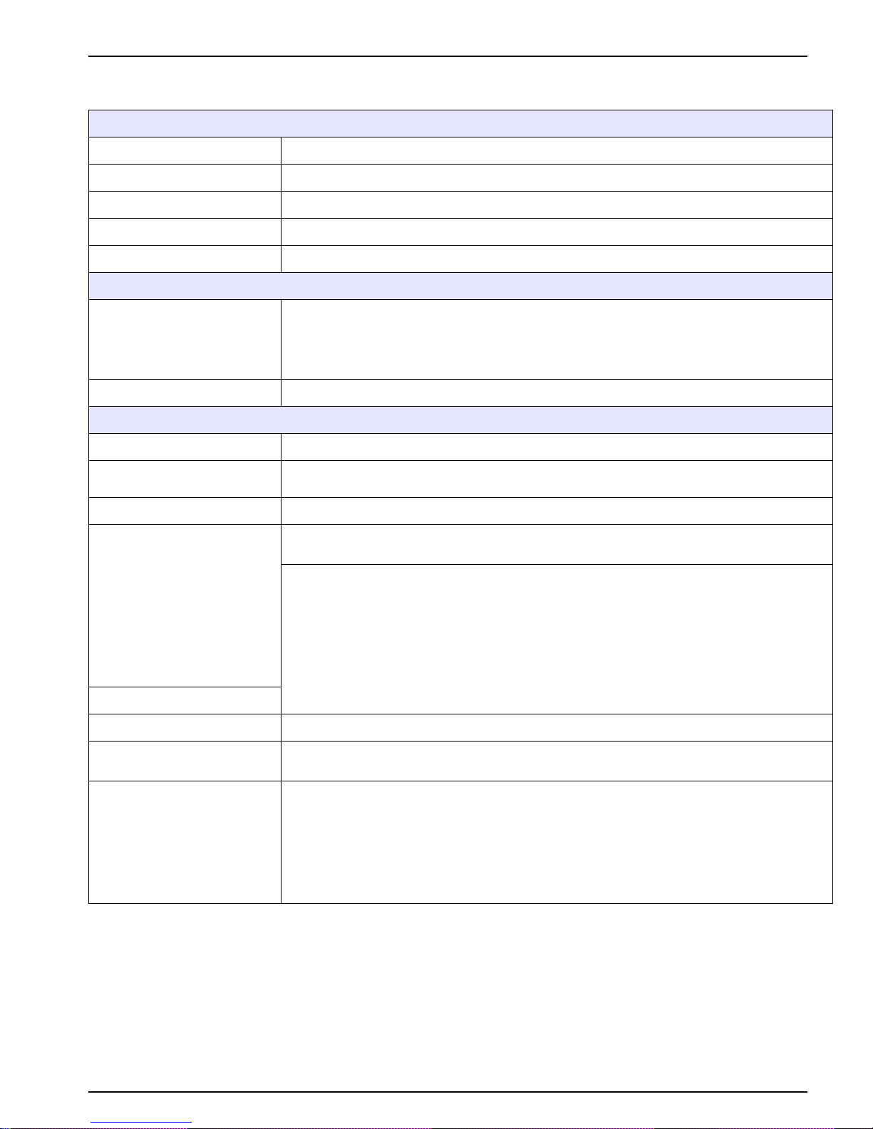
Section 1 Specifications
From software version 1.6. Subject to change.
Measurement
Principle of operation Samples delivered under pressure, homogenized using ultrasound
Interval 12 to 20 minutes
Sample quantity For up to 2 PHOSPHAX sigma or TOCTAX process photometers
Tube length 10 m, 20 m, 30 m (393.7 in, 787.4 in, 1181.1 in)
Suction height Maximum 7 m (275.6 in) (with tube of length 30 m (1181.1 in): maximum 6 m 236.2 in)
Environmental cond iti ons
Ambient temperature
Control unit: +5 °C to +40 °C (+41 °F to +104 °F)
Connection tube: –20 °C to +40 °C (–4 °F to +104 °F)
(Without additional insulation; in the event of low external temperatures, correct operation can
only be guaranteed with additional insulation. More information available on request)
Medium temperature +5 °C to + 30 °C (+41 °F to +86 °F) (probe)
Equipment properties
Protection type in accordance with IP 54 (Control unit)
Outputs
Fault indication contact, potential-free, 24 V, maximum 1 A
Service interface: RS 232
Power connector 230 V AC / 50 Hz
Power consumption
Device with system components : 600 VA
Recommended fuse: 10 A, time-delay
Line Heater off Heater on (–20 °C (–4 °F))
Continuous
operation
At startup
10 m (393.7 in) 150 VA 250 VA 1300 VA
20 m (787.4 in) 150 VA 350 VA 2300 VA
30 m (1181.1 in) 150 VA 470 VA 3000 VA
Inspection interval: 3 months
Maintenance requirement: Approximately 0.5 h/week, typically
Dimensions:
Open loop control unit: W × H × D 366 × 560 × 212 mm (14.4 × 22 × 8.3 in
Probe: Ø × L 133 × 404 mm (5.2 × 15.9 in
Earth (approximate)
Control unit: 12 kg
Sampling probe 10 m (393.7 in) 7.5 kg
Sampling probe 20 m (787.4 in) 15 kg
Sampling probe 30 m
(1181.1 in)
22 kg
Mounting poles: 10 kg
Page 6

6
Specifications
Page 7
7
Section 2 General Information
2.1 Safety information
Please read this entire manual before unpacking, setting up, or operating this equipment.
Pay attention to all danger and caution statements. Failure to do so could result in serious
injury to the operator or damage to the equipment.
To prevent damage to or impairment of the device's protection equipment, the device may
only be used or installed as described in this manual.
2.1.1 Use of hazard information
Note: Information that supplements points in the main text.
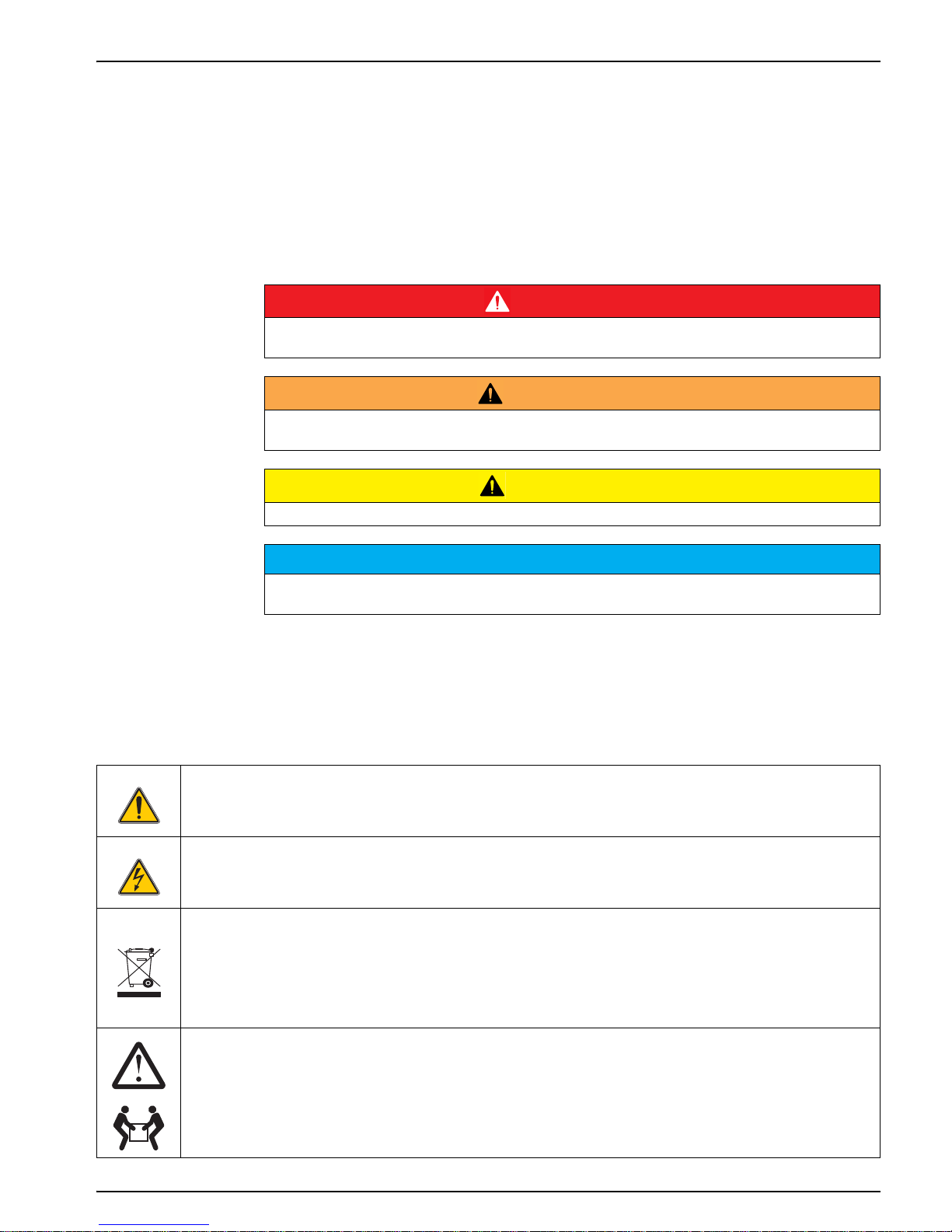
2.1.2 Precautionary labels
Observe all labels and notices attached to the instrument and/or delivery packaging.
Personal injury or damage to the instrument could occur if not observed.
DANGER
Indicates a potentially or imminently hazardous situation that, if not avoided, can result in death or
serious injury.
WA RN IN G
Indicates a potentially or imminently dangerous situation that, if it is not avoided, can lead to
death or to serious injuries.
CAUTION
Indicates a possible dangerous situation that can have minor or moderate injuries as the result.
NOTICE
Indicates a situation that, if it is not avoided, can lead to damage to the device. Information that
requires special emphasis.
This symbol, if noted on the instrument, references the instruction manual for operation and/or safety
information.
This symbol may be found on an enclosure or barrier within the product and indicates a risk of electric shock
and/or death by electrocution.
Electrical equipment marked with this symbol may not be disposed of in European domestic or public disposal
systems after 12 August 2005. In conformity with European local and national regulations (EU Directive
2002/96/EC), European electrical equipment users must now return old or end-of life equipment to the
manufacturer for disposal at no charge to the user.
Note: You obtain instructions on the correct disposal of all (marked and not marked) electrical products that
were supplied or manufactured by Hach-Lange at your relevant Hach-Lange sales office.
When carrying or transporting the instrument/instrument components and if the total weight is more than 18 kg,
make sure that suitable lifting equipment is used and/or that the instrument/instrument components are carried
by 2
people.
18-32 kg (39.7-70.5 lbs)
Page 8
8
General Information
2.2 Application areas
Automatic sample removal and homogenization system for supplying the PHOSPHAX S
sigma (total phosphorus), TOCTAX (total organic carbon, TOC) and astro TOC (total
organic carbon, TOC) process photometers with samples from water containing solid
particles with a diameter < 0.5 mm.
2.3 Functional description
A sampling probe is immersed in the water and draws only the sample volume required for
the analysis without coming into contact with pumps. The sample is conveyed into a small
storage vessel in the open loop control unit and is homogenized using an ultrasound
generator.
NOTICE
Any use other than use in accordance with requirements defined in the user manual leads to the
loss of the warranty claims and can lead to personal injury and property damage, for which the
manufacturer assumes no liability.
Page 9
9
General Information
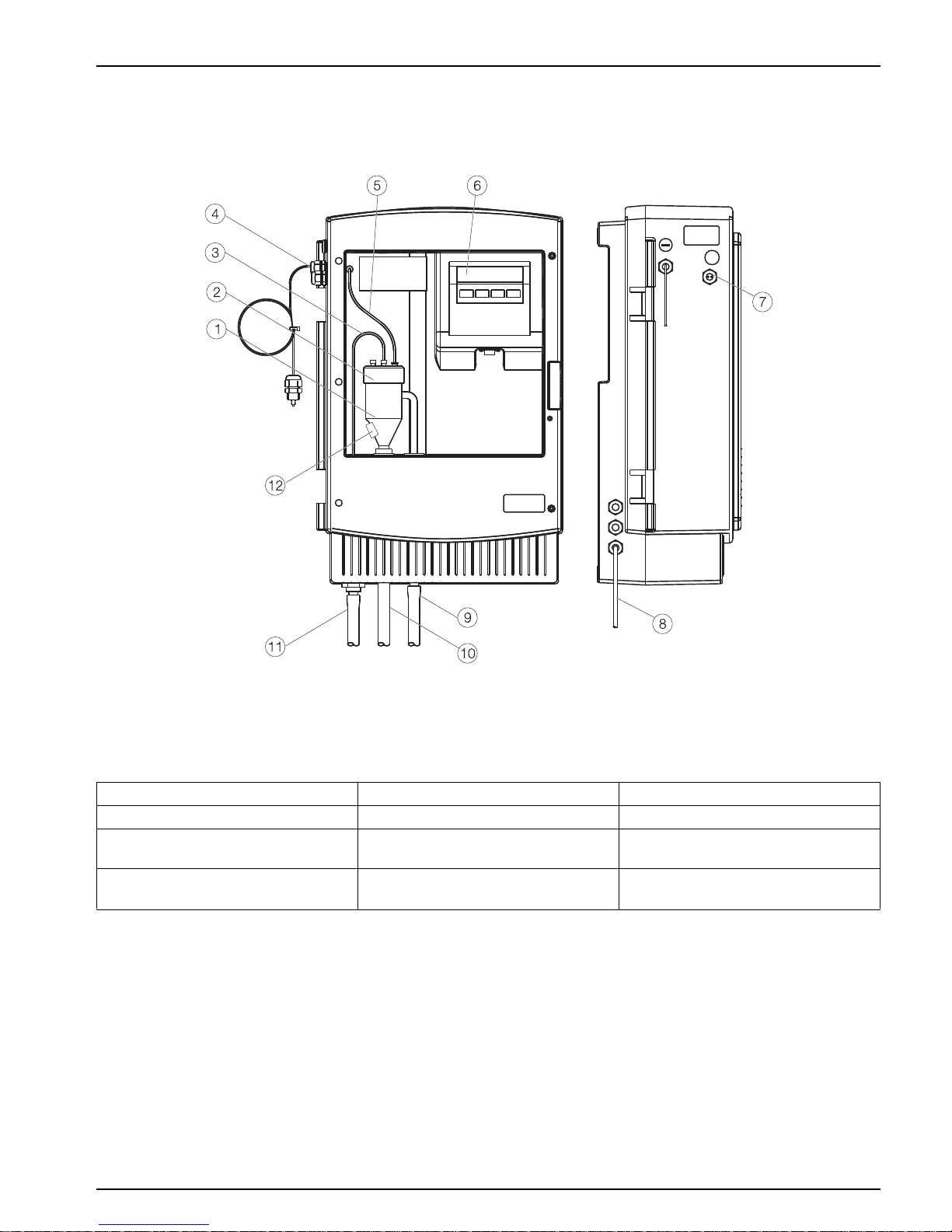
2.4 Instrument design
Figure 1 Control unit
1 Sample storage vessel 5 Pressure sensor line 9 Overflow drain tube
2 Sample storage vessel lid 6 Display with keypad 10 Sample storage vessel drain tube
3 Sample tube 7 Sample removal for process
instruments
11 Connection tube from the probe
4 Fiber optic cable for
PHOSPHAX
sigma or TOCTAX
8 Mains connection cable 12 Ultrasound transducer
Page 10
10
General Information
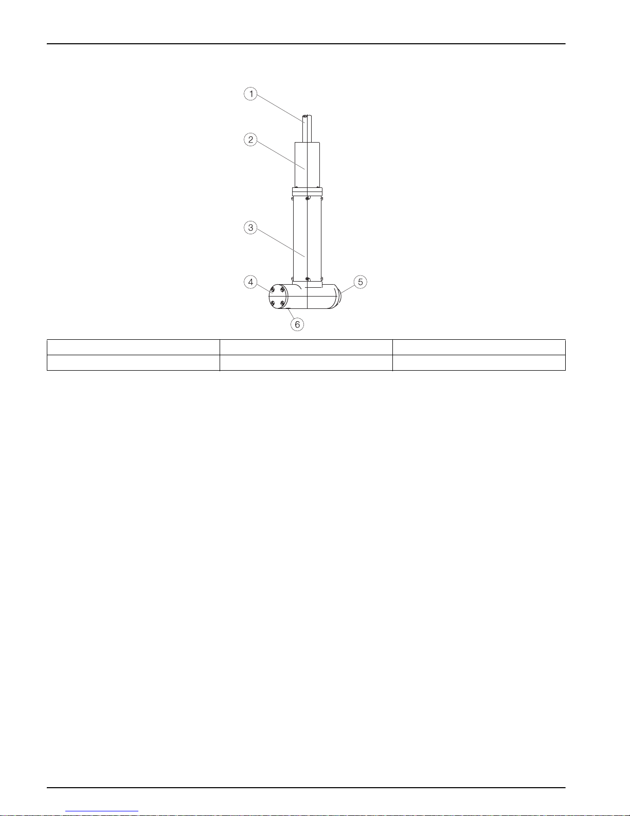
Figure 2 Sampling probe
1 Connection tube 3 Sampling vessel 5 Air outlet
2 Probe cover 4 Valve cover 6 Drain valve
Page 11
11
Section 3 Installation
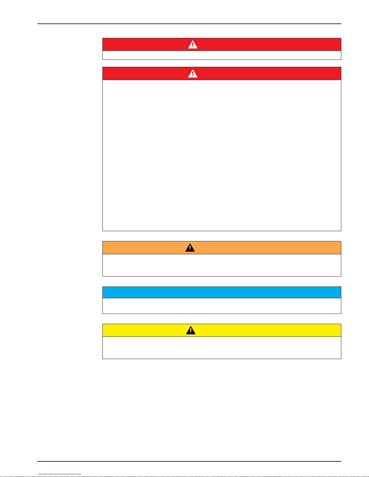
DANGER
Only qualified experts may conduct the tasks described in this section.
DANGER
Select a suitable attachment point for the instrument.
Plan out the mechanical mount·before positioning poles or drilling holes. Make sure the mount
has a sufficient bearing capacity. The dowels must be selected and authorized according to the
condition of the wall.
The manufacturer shall accept no liability if the instrument is installed incorrectly.
Plan how to lay cables and tubes and their path in advance. Lay the tubes, data cables and
power cables without any bends and so they do not pose a tripping risk.
Do not connect the electrical supply to the mains·until the instrument is completely wired and
protected against short circuits.
Sufficiently protect the electrical power supply against short circuits.
For the external power supply, always connect a residual-current circuit breaker·(trip current
max.: 30 mA) between the mains and the system.
If the instrument is to be installed outdoors, connect a surge arrester between the mains and the
system.
Products intended by the manufacturer for outdoor use offer a higher level of protection against
the penetration of liquids and dust. If these products are connected to a mains outlet with a cable
and plug·rather than a permanently connected cable, the plug and outlet are much more
susceptible to liquid and dust penetration. The operator must sufficiently protect the plug and
outlet against liquid and dust penetration in accordance with local safety regulations. If the
instrument is to be used outdoors, it must be connected to a suitable outlet with a protection type
of at least IP44 (splash protection).
WA RN IN G
Electrical and fire hazards. Only use the mains cable supplied. Only qualified experts may
perform the tasks described in this section of the manual, while adhering to all locally valid safety
regulations.
NOTICE
Protect the instrument from extreme temperatures from heaters, direct sunlight and other heat
sources.
CAUTION
Beware of the weight (open loop control unit: approximately 12 kg; sampling probe up to
approximately 22 kg) of the instrument and the probe. Do not attempt to carry the instrument and
probe without assistance. Use only suitable lifting devices for the transport.
Page 12
12
Installation
3.1 Mechanical installation
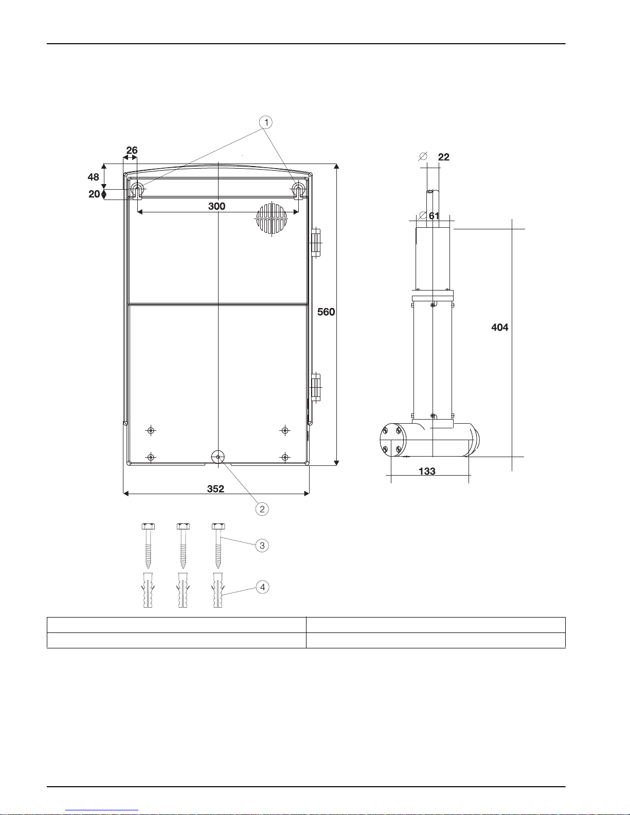
Figure 3 Dimensions (in mm)
1 Suspension points 3 Wood screw, 5 x 40 (3×)
2 Fixing point 4 Nylon plug, 8 x 40 (3×)
Page 13

13
Installation
Figure 4 Installation overview
1 SIGMATAX 2 open loop control unit 4 Mounting attachment 7 SIGMATAX 2 sampling probe
2 Connection tube (10–30 m) 5 Base 8 Direction of flow
3 Retaining clamp 6 Mounting pipe, 2 m (78.7 in)
aaaaaaaa
aaaaaaaa
aaa
aaa
Page 14
14
Installation
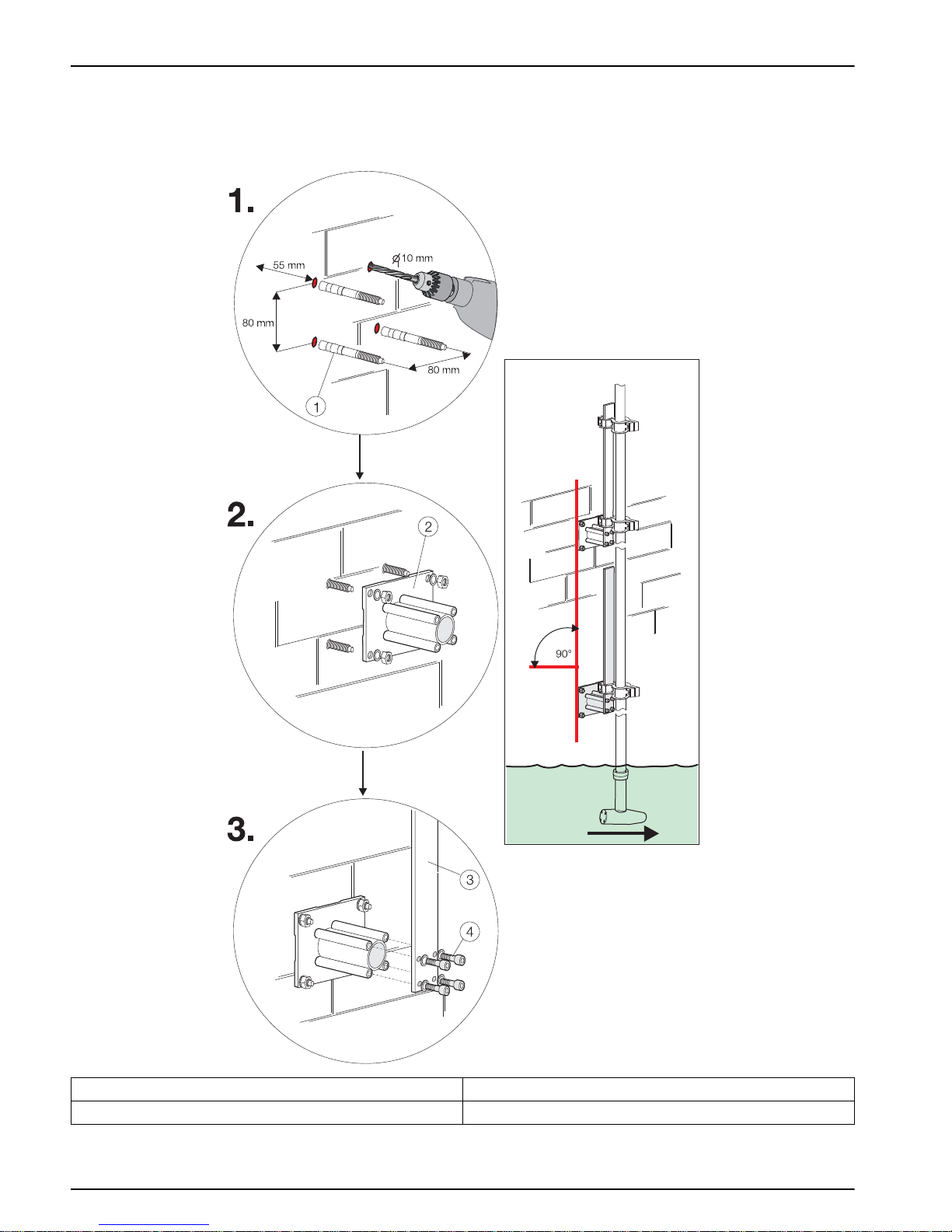
3.1.1 Install the sampling probe
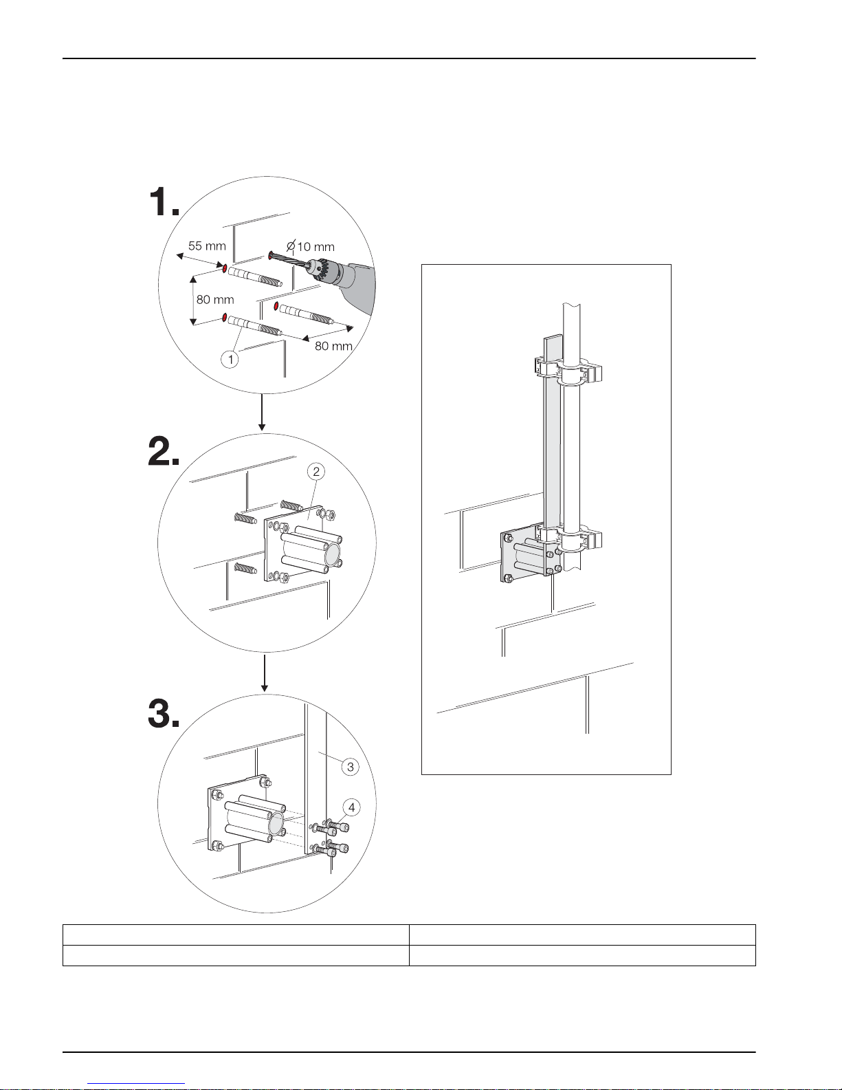
Installation with rim mounting LZX414.00.00000
Figure 5 Base and mounting attachment
1 Express anchor 3 Mounting attachment
2 Base 4 Cylinder-head screw, M8 × 40 (4×)
Page 15
15
Installation
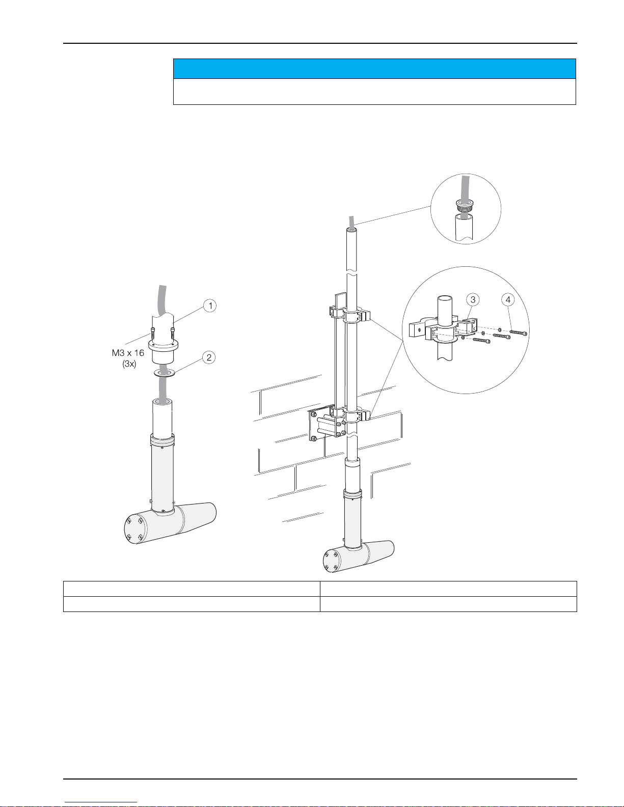
Installation using pole mount LZX414.00.00000
Figure 6 Sampling probe and mounting pipe
NOTICE
When carrying out an installation variant that deviates from this example, make sure that the
connection tube from the sampling probe is guided vertically upward for at least 0.5
m (19.6 in).
1 Mounting pipe, 2 m (78.7 in) 3 Retaining clamp
2 EPDM flat seal 4 Cylinder-head screw, M5 × 20 (3×)
Page 16
16
Installation
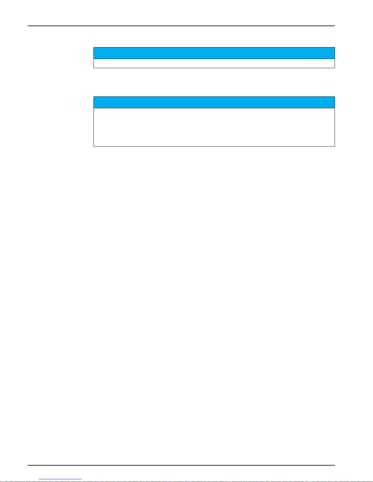
3.1.2 Second mounting point and extension pipe
Figure 7 Second mounting point LZX456
1 Mounting pipe, 2 m (78.7 in) 3 Retaining clamp
2 EPDM flat seal 4 Cylinder-head screw, M5 × 20 (3×)
Page 17
17
Installation
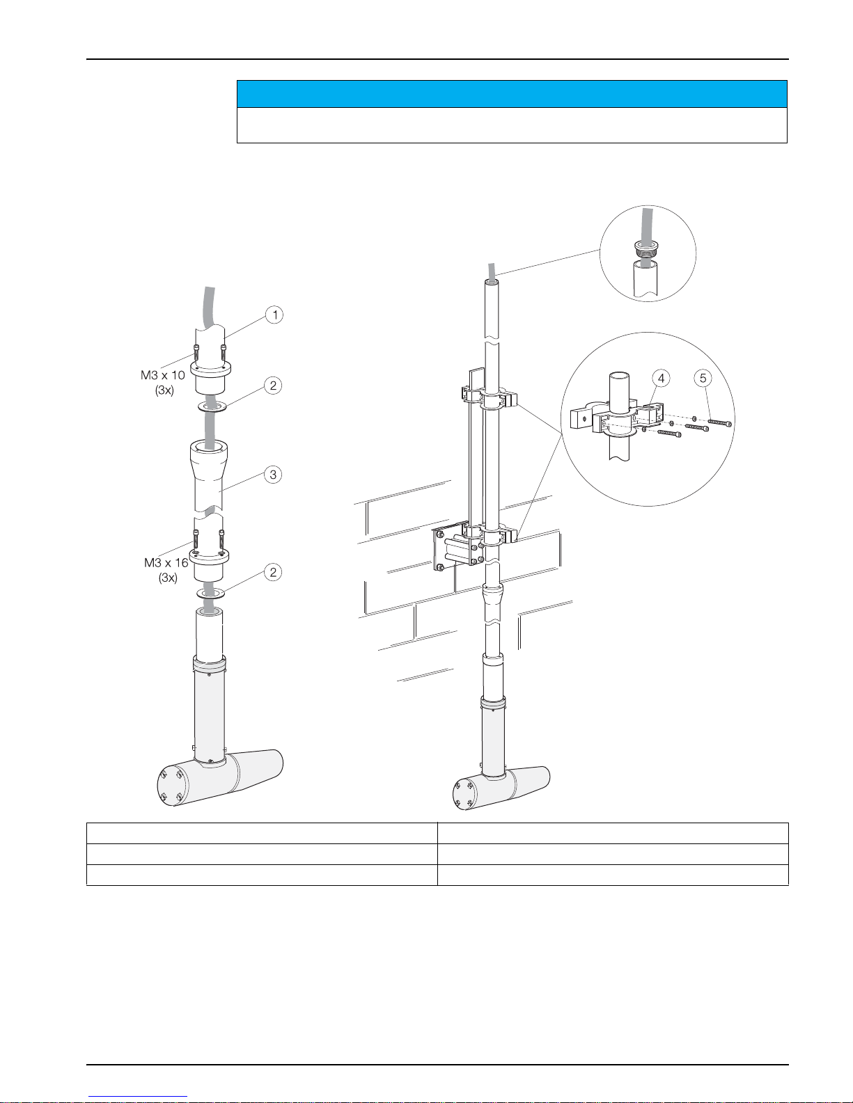
Figure 8 Installation with extension pipe.
NOTICE
When carrying out an installation variant that deviates from this example, make sure that the
connection tube from the sampling probe is guided vertically upward for at least 0.5
m (19.6 in).
1 Mounting pipe, 2 m (78.7 in) 4 Retaining clamp
2 EPDM flat seal 5 Cylinder-head screw, M5 × 20 (3×)
3 Extension pipe
Page 18
18
Installation
3.1.3 Install the open loop control unit
Make sure that an area of 5 cm is kept free around the entire instrument to enable air to
circulate (distance from the wall of the building, cable channel etc.).
NOTICE
Install the open loop control unit in a dry location out of direct sunlight.
NOTICE
The Teflon sample lines must be laid without sharp bends. Shortening or extending the lines will
lead to problems when the samples are transported.
Each process instrument must have a separate drain tube!
The individual device drains may only be combined in a larger drain pipe with regular water
throughput.
Page 19
19
Installation
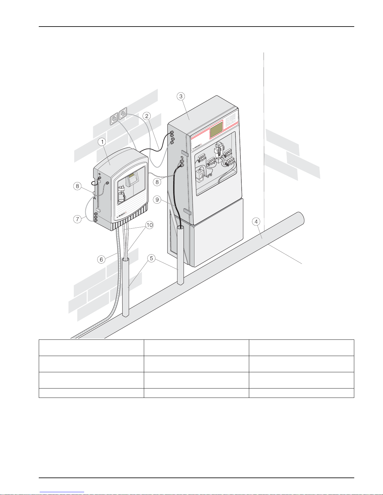
Figure 9 Open loop control unit and process instrument
1 SIGMATAX 2 open loop control unit 5 Separate drain pipe for process
instrument
9 Drain tube for process instrument
2 Fiber optic cable to the process
instruments
6 SIGMATAX 2 connection tube 10 SIGMATAX 2 drain tubes
3 PHOSPHAX sigma or TOCTAX 7 SIGMATAX 2 mains connection
cable
4 Shared drain pipe 8 Teflon sample line
Page 20
20
Installation
3.1.4 Prepare the connection tube
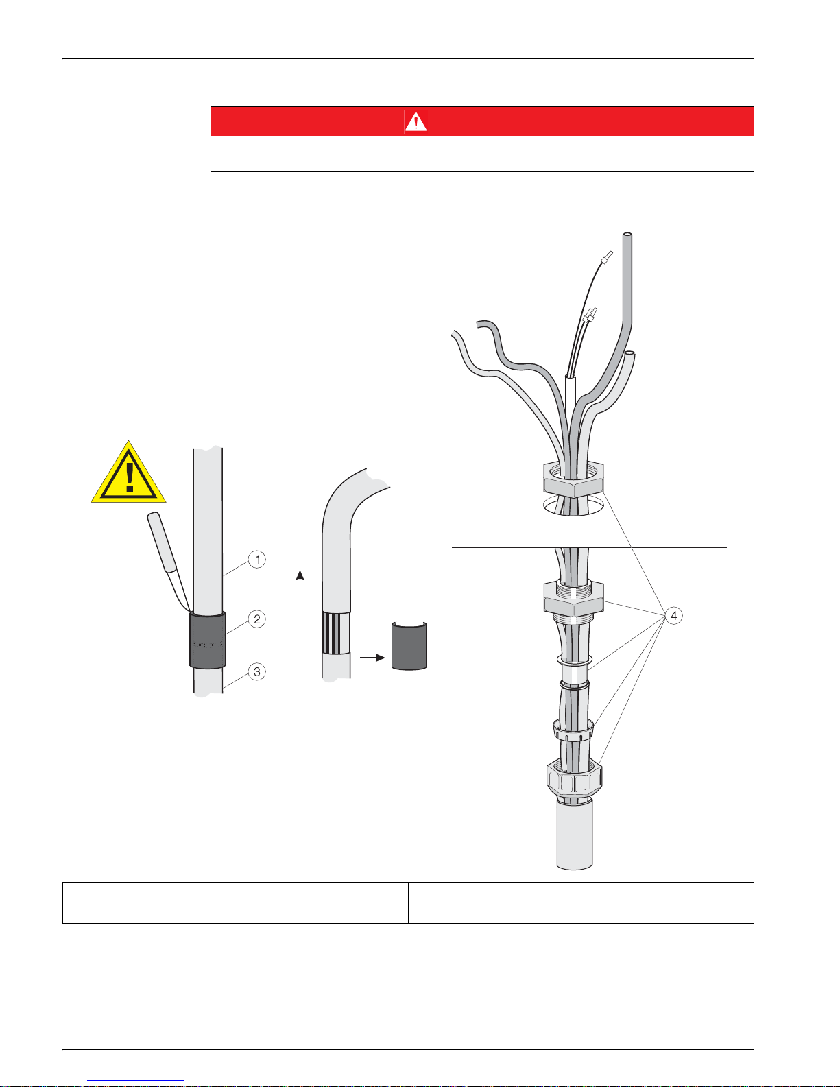
Figure 10 Connection tube
DANGER
The pipe trace heater in the connection tube is operated at 230 V. If any damage occurs to the
tube casing, the entire system must be taken out of operation immediately.
1 Protective tube 3 Connection tube
2 Heat-shrink tube 4 PG 16 screw connection
Page 21
21
Installation
3.1.5 Connect the connection tube
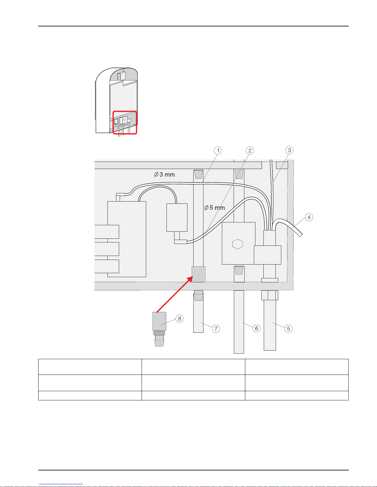
Figure 11 Connections for connection tube and drain tubes
1 Air hose (drain valve), Ø 3 mm
(0.11 in)
4 Electrical connection cable for the
pipe trace heater
7 Overflow drain tube
2 Air hose, Ø 5 mm (0.19 in) 5 Connection tube from the sampling
probe
8 Drain fitting
3 Sample tube 6 Drain tube for storage vessel
Page 22
22
Installation
3.2 Electrical installation
3.2.1 Connect the pipe trace heater and fault indication contact
NOTICE
Protect the instrument from extreme temperatures from heaters, direct sunlight and other heat
sources.
WA RN IN G
Electrical and fire hazards. Use only the supplied power cable.
Only qualified experts may perform the tasks described in this section of the manual, while
adhering to all locally valid safety regulations.
NOTICE
Use only earthed sockets for the connection of this device to the power supply.
If you are not sure if the sockets are earthed, have this checked by a qualified electrician.
The power plug serves in addition to the power supply to isolate the device quickly from the
mains where necessary.
The entire measurement system has two power plugs (measurement device and open loop
control unit).
During the disconnection from the power source it must be made sure that the correct power plug
is pulled (for example by labeling the sockets).
This is recommended for long-term storage and can prevent potential dangers in the event of a
fault.
Therefore make sure that the sockets to which the device is connected are easy to reach by each
user at all times.
NOTICE
Pull out power plug before the opening of the device.
WA RN IN G
The electrical connection for the pipe trace heater must be carried out by a specialist electrician.
NOTICE
If the mains plug·of the power connection cable·is removed and replaced by hard wiring, then in
immediate proximity of the display unit a suitable double-pole one-way circuit breaker with clear
labeling for the power supply must be installed.
All connected signal connection lines must be shielded.
Page 23
23
Installation
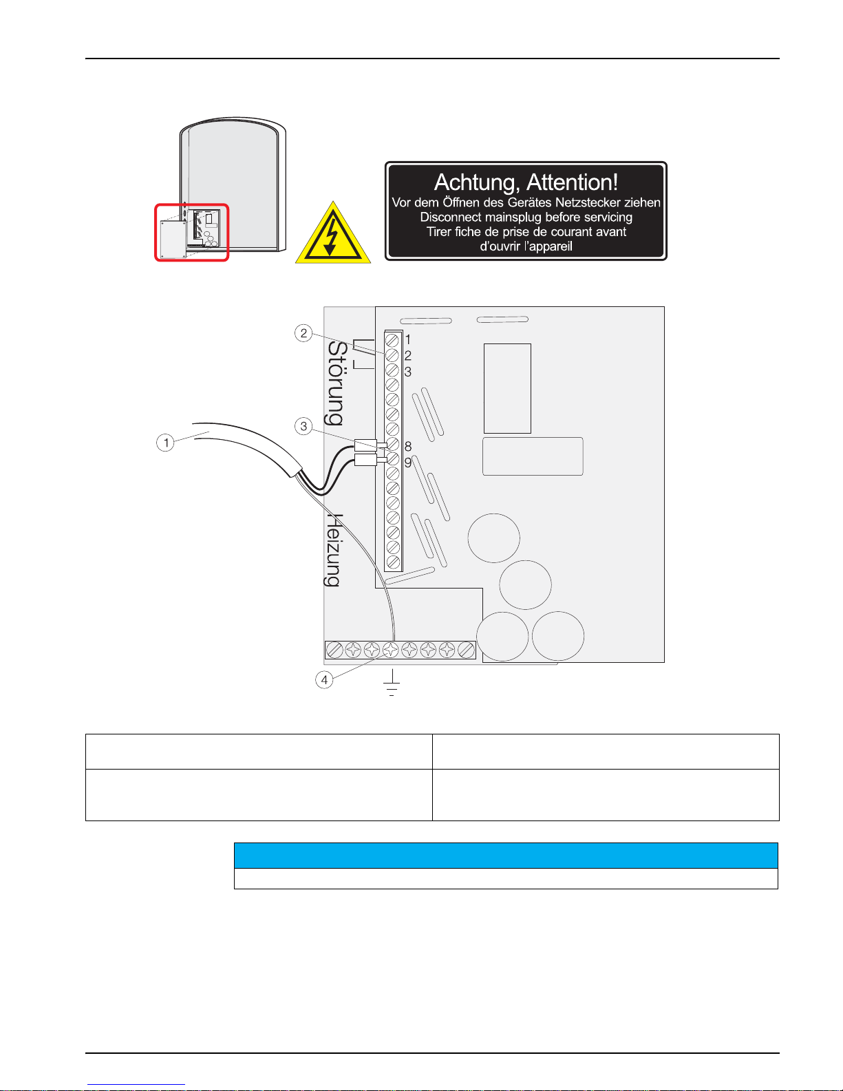
Figure 12 Terminal assignment
1 Connection cable for pipe trace heater 3 Connection terminals for heater
(N, L = terminals 8 + 9 from the top)
2 Fault indication contact (circuit diagram shows contact
during a fault indication)
Open 1/2, closed 2/3
4 Connection terminal for earth conductor
NOTICE
Route the signal lines (1, 2, 3) separated from the power cable.
Page 24
24
Installation
3.2.2 Connect the fiber optic cable
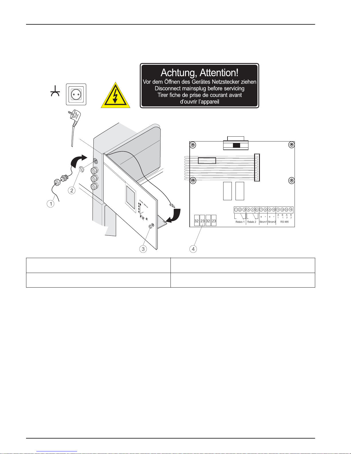
Figure 13 Fiber optic cable connection
3.3 Internal tubing
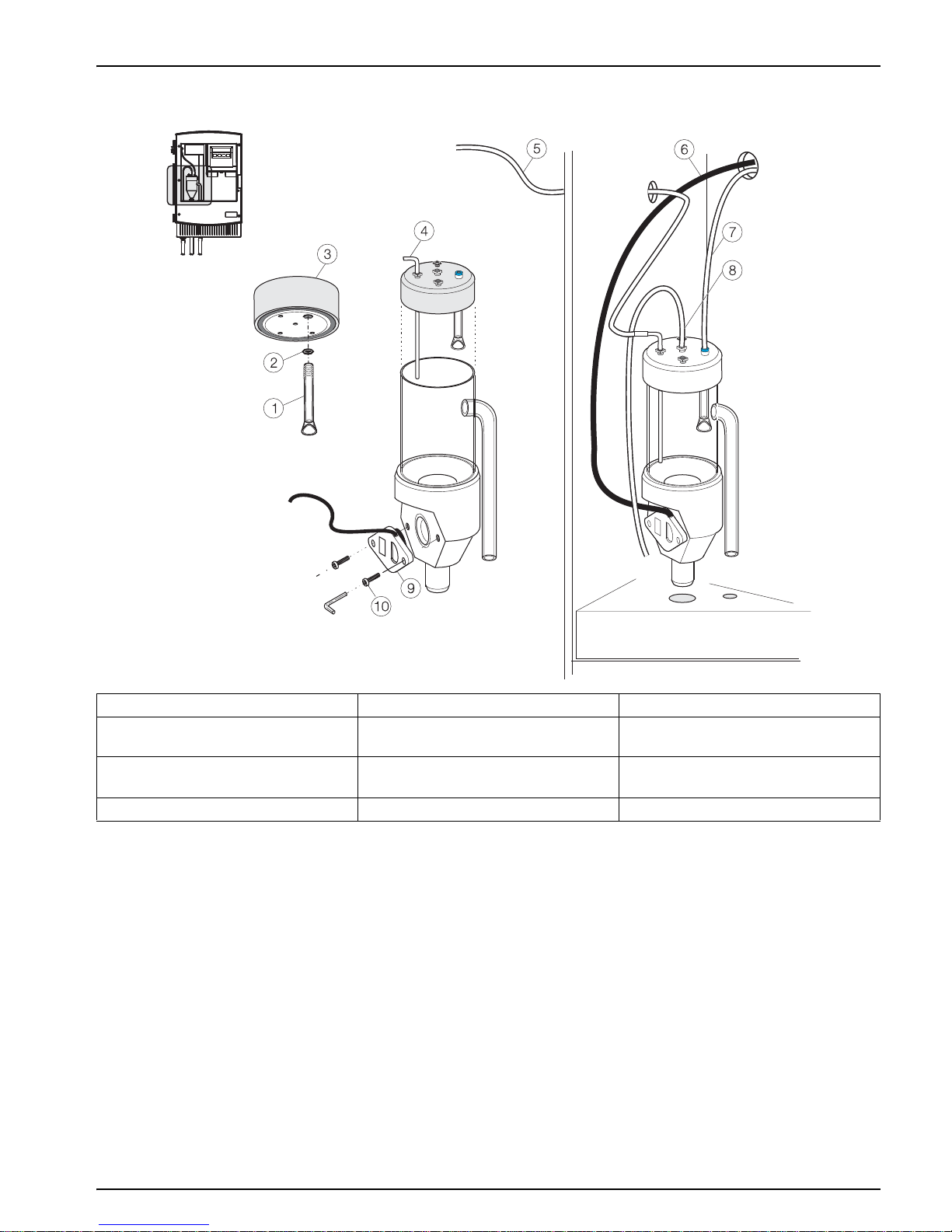
1. Carefully screw the level indicator tube (1) and O-ring (2) into the cover (3) from
below.
2. Connect the sampling line (5) to the sampling pipe (4). Then insert the sampling pipe
all the way into the cover through opening 3 or 4.
Note: Fragile glass components
3. Lubricate the rubber seal of the ultrasound transducer (9) with Baysilone paste.
4. Attach the ultrasound transducer (9) to the sample storage vessel using the two
cross-head screws (10). Install the ultrasound transducer in line with the illustration
(cable "upward").
5. Connect the pressure sensor line (7) and insert the sample delivery line (8) 1 cm
(0.39
in) through the central opening in the cover.
1 Fiber optic cable for SIGMATAX 2 with PG screw
connection
3 Knurled-head screw for opening the front panel
2 Blind plug for fiber optic cable PG screw connection
(PHOSPHAX sigma or TOCTAX)
4 Fiber optic cable connection
Page 25
25
Installation
Figure 14 Sample storage ve ssel
1 Level indicator pipe 5 Sample tube 9 Ultrasound transducer
2 O-ring 6 Connection cable for ultrasound
transducer
10 Cross-head screw, M4 × 16 (2×)
3 Sample storage vessel cover with
O-ring compression fittings
7 Pressure sensor line
4 Small sample pipe 8 Sample tube
Page 26

26
Installation
Page 27
27
Section 4 Start Up
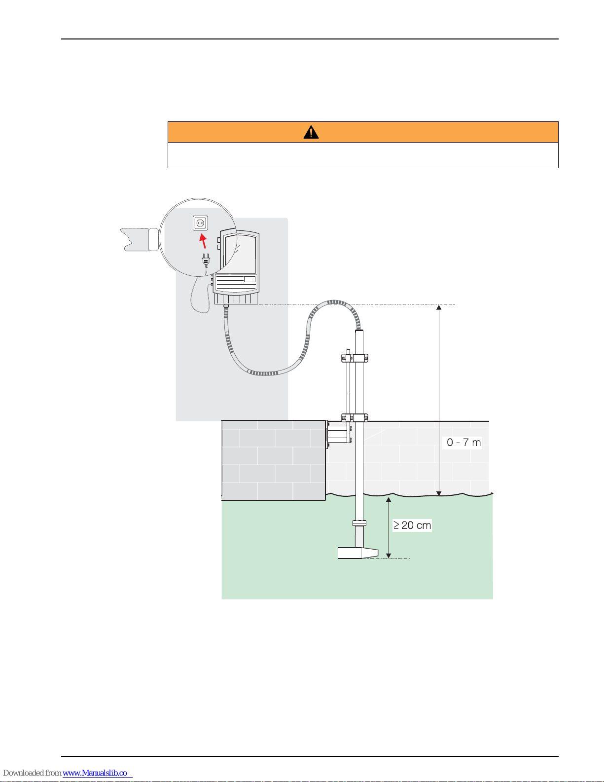
After the sampling probe and control unit have been fully installed and all lines have been
connected (connection tube, sampling and drain tubes, fiber optic cables), the mains plug
can be plugged in.
If there is a risk of freezing, switch on the pipe trace heater!
Figure 15 Plug in the power plug
WA RN IN G
The pipe trace heater in the connection tube is operated at 230 V. If any damage occurs to the
tube casing, the entire system must be taken out of operation immediately.
aaaaaaaa
aaaaaaaa
aaa
aaa
Page 28

28
Start Up
Page 29
29
Section 5 Operation
5.1 Operation
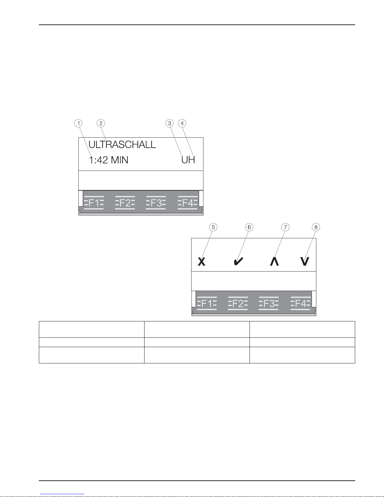
All instrument functions are controlled by the software. The instrument is operated via
menus using four keys that are located below the display. From operational mode, you can
access the first menu level by pressing the function keys, F1 to F4, for 3 seconds.
The functions of the keys in the individual menus may vary, and are therefore shown
(abbreviated clearly) in the second row of the display (softkey function).
Figure 16 Display and keypad
1 Time remaining for current process 4 Operational status of heater
("H" visible = heater active)
7 Go back to previous menu item
2 Current status message 5 Cancel 8 Go to next menu item
3 Operational status of ultrasound
("U" visible = ultrasound active)
6 Setting change
Page 30
30
Operation
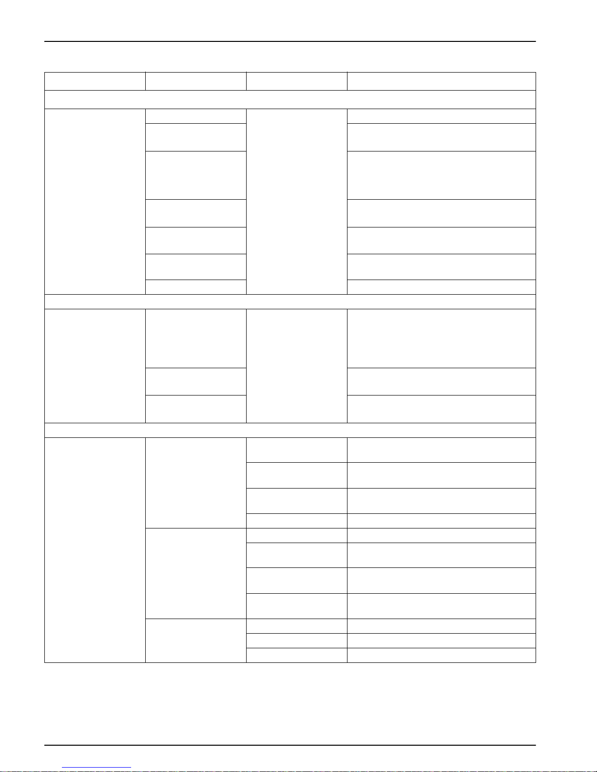
5.2 Menu overview
Menu level 1 Menu level 2 Menu level 3 Description
+SETTINGS
for parameterizing the
instrument
Language Option to select the language for the menus
HEATER Self-adjusting pipe trace heater —
turn on if there is a risk of freezing!
Interval
Time interval (6–60 minutes) between
2
samples.
An interval > 12 minutes is only necessary for
longer analysis periods
Probe type
Length of connection tube (10–30 m
(393.7–1181.1
in)
Contrast
Reading angle (0–30) of the display;
temperature dependent
press. indic.
Pressure display on the screen; can be
switched off
Version Instrument type and program version
+OUTPUT TEST
for testing
connected
data cables
error indication
Switches on the potential-free fault indication
contact for 2
seconds
The fault indication contact is only held in
the previous position for as long as the
user activates it for testing purposes.
fiber optic 1
Blanks fiber optic cable 1 for 1 second
fiber optic 2
Blanks fiber optic cable 2 for 1 second
OF output 2
+SERVICEMENU
for maintenance tasks
and functional tests
+INSPECTION:
SIGMATAX switches to
service mode
clean.samp. tube
Cleans the sample tube (assisted by the
program)
cleaning probe
Cleans the sampling probe (assisted by the
program)
blowing probe
Automatically cleans the sampling probe with
air
blowing valve Automatically cleans the drain valve with air
+FUNCTIONSTEST
SIGMATAX switches
to service
mode
compressor Activates compressor for 30 seconds
probe valve
Automatically open and close the
probe valve
ultrasonic
Takes a new sample and activates
ultrasound for 30 seconds
drain valve
Automatically opens and closes the drain
valve
+ERROR STATUS
filling error Counter for filling errors that have occurred
delivery error Counter for delivery errors that have occurred
error reset Reset the counters to "0"
Page 31

31
Operation
5.3 Important instrume nt settings
5.3.1 Switch on the heater
1. Press one of the function keys, F1 to F4, for 3 seconds.
2. Open the +SETTINGS menu by pressing F2.
3. Press F4 to scroll to the [heating] menu item
4. Select this menu item by pressing F2.
5. Switch the heater on or off by pressing F3 or F4.
6. Confirm by pressing F2 and exit this menu level by pressing F1.
5.3.2 Set the processing interval
1. Press one of the function keys, F1 to F4, for 3 seconds.
2. Open the +SETTINGS menu by pressing F2.
3. Press F4 twice to scroll to the [interval] menu item.
4. Select this menu item by pressing F2.
5. Set the desired interval by pressing F3 and F4.
6. Confirm by pressing F2 and exit this menu level by pressing F1.
5.3.3 Set the display contrast
1. Press one of the function keys, F1 to F4, for 3 seconds.
2. Open the +SETTINGS menu by pressing F2.
3. Press F4 four times to scroll to the [contrast] menu item.
4. Select this menu item by pressing F2.
5. Set the desired contrast by pressing F3 and F4.
6. Confirm by pressing F2 and exit this menu level by pressing F1.
5.3.4 Switch on the pressure display
1. Press one of the function keys, F1 to F4, for 3 seconds.
2. Open the +SETTINGS menu by pressing F2.
3. Press F4 five times to scroll to the [press indic.] menu item.
4. Select this menu item by pressing F2.
5. Switch the pressure indicator on or off by pressing F3 or F4.
6. Confirm by pressing F2 and exit this menu level by pressing F1.
STATUS U O
Open the probe 0 to minimum –0.5 bar –
Close the probe 0 to minimum 1.3 bar –
Deliver the sample > 1.6 bar 10–16
Empty the probe 0.1–0.5 bar –
Page 32

32
Operation
5.3.5 Access service mode
1. Press one of the function keys, F1 to F4, for 3 seconds.
2. Press F4 twice to scroll to the [+SERVICEMENU] menu.
3. Press F2 to open this menu.
4. When the [+INSPECTION] or [+FUNCTION TEST] menus are selected, the system
automatically switches to service mode.
Service mode means that:
• The instrument is no longer in operational mode
• The sampling probe and sample storage vessel are empty
• The system is depressurized
• The sampling probe is closed
• The fault indication contact remains in the last valid position
• The instrument will not switch back automatically to operational mode
Page 33

33
Section 6 Maintenance
The manufacturer recommends that an inspection contract be concluded. This contract
extends the warranty period to 5 years and makes sure that all inspection and
maintenance tasks are carried out by qualified experts.
Maintenance tasks for users are limited to regular visual inspections and, if necessary,
cleaning procedures.
Maintenance schedule DOC273.72.04008.MRZ03
Type of
device:
◦ 10 m ◦ 20 m ◦ 30 m Instrument number:
Commissioning on: by:
Annually:
Seal membrane on relief valve
Every 1.5 years:
Replace compressor
Every 3 months:
Clean supply lines and
sampling probe (interior)
Test pressure
Every 6 months:
Replace valve piston with seal
kit
Heat if there is a risk of
freezing!
Weekly:
Clean sample storage vessel
Visually inspect sample quality
Every 1–4 weeks:
Check/clean sampling probe
Clean sample tube
(semi-automatic)
Page 34
34
Maintenance
6.1 Maintenance tasks
6.1.1 After 1–4 weeks (as necessary)
Clean the sample tube
1. In the [+SERVICEMENU] menu, open the [+INSPECTION] submenu and the
[clean.samp. tube]menu item.
2. The individual steps are specified here and carried out with the support of the
program (see table).
DANGER
Potential dangers with contact with chemical/biological substances.
Working with chemical samples, standards and reagents is linked with dangers.
Make yourself familiar with the necessary safety procedures and the correct handling of the
chemicals before the work and read and follow all relevant safety data sheets.
WA RN IN G
Before handling these substances observe all danger notes and safety information printed on the
containers of the original solutions and in the safety data sheet.
Dispose of all consumed solutions in accordance with the national regulations and laws.
Select the type of protective equipment suitable to the concentration and quantity of the
dangerous material being used.
Display text Description/action
clean. samp. tube Begin the cleaning tasks supported by the program for the sample tube; start
by pressing F4
clean. samp. tube Confirmation prompt; confirm by pressing F4
cleaning glass inserted? Replace the sample storage vessel with the cleaning vessel, which contains
chlorine bleach (sodium hypochlorite), and confirm by pressing F4.
sample tube advanced? Feed the sample tube through to the base of the cleaning vessel and confirm
by pressing F4.
opening probe cleaning
emptying probe cleaning
affecting
tube xx sec
please wait xx sec
The cleaning solution is automatically sucked in for 60 seconds. In the
meantime, the sample storage vessel can be cleaned using a paper towel
and, if necessary, a little window cleaning solution or diluted hydrochloric
acid.
sample glass inserted? Insert the sample storage vessel again and confirm by pressing F4
sample tube retracted Retract the sample tube and confirm by pressing F4
from cleaning to At this point, it is possible to choose whether SIGMATAX calls up the
[+SERVICEMENU] menu and remains in SERVICE mode, or whether it
switches to operational mode.
Test/maint Operation
opening probe cleaning
emptying probe cleaning
filling probe cleaning
closing probe cleaning
deliv. sample cleaning
emptying sample tube cleaning
The program runs through an automatic rinsing function to remove the
residual cleaning solution by repeatedly filling and emptying the system.
[+SERVICEMENU] or operation Status after rinsing is complete
Page 35
35
Maintenance
6.1.2 1×/month (or as necessary)
Clean the sampling probe
1. In the [+SERVICEMENU] menu, open the [+INSPECTION] submenu and the
[cleaning probe] menu item.
2. The individual steps are specified here and carried out with the support of the
program (see table).
DANGER
Potential dangers with contact with chemical/biological substances.
Working with chemical samples, standards and reagents is linked with dangers.
Make yourself familiar with the necessary safety procedures and the correct handling of the
chemicals before the work and read and follow all relevant safety data sheets.
WA RN IN G
Before handling these substances observe all danger notes and safety information printed on the
containers of the original solutions and in the safety data sheet.
Dispose of all consumed solutions in accordance with the national regulations and laws.
Select the type of protective equipment suitable to the concentration and quantity of the
dangerous material being used.
Display text Description/action
cleaning probe Begin the cleaning tasks supported by the program for the sampling probe;
start by pressing F4
cleaning probe Confirmation prompt; confirm by pressing F4
probe in clean.solution? Immerse the sampling probe in a bucket containing cleaning solution (rinsing
agent) and confirm by pressing F4
pressure comp.
opening probe cleaning
emptying probe cleaning
filling probe cleaning
closing probe cleaning
The sampling probe is automatically filled with cleaning solution.
was probe shaken?
You can assist the cleaning process mechanically. To do this, simply shake
the probe and confirm by pressing F4
opening probe cleaning
emptying probe cleaning
closing probe cleaning
The sampling probe empties automatically and rinses the removed solids out
into the bucket with the cleaning solution.
probe back in basin? Immerse the sampling probe again at the sampling location and confirm by
pressing F4
from cleaning to At this point, it is possible to choose whether SIGMATAX calls up the
[+SERVICEMENU] menu and remains in SERVICE mode, or whether it
switches to operational mode.
Test/maint Operation
opening probe cleaning
emptying probe cleaning
filling probe cleaning
closing probe cleaning
The program runs through an automatic rinsing function, filling and emptying
the system to remove the residual cleaning solution.
[+SERVICEMENU] or operation Status after rinsing is completed
Page 36

36
Maintenance
Page 37

37
Section 7 Troubleshooting
As soon as a fault leads to an interruption in operation, SIGMATAX 2 immediately
switches to service mode. Corresponding error messages are shown both on the
SIGMATAX 2 display and on the displays of the connected process photometers.
Service mode means that:
• The instrument is no longer in operational mode
• The sampling probe and sample storage vessel are empty
• The system is depressurized
• The sampling probe is closed
• The fault indication contact is held in the last valid position
• The instrument will not return automatically to operational mode
Error message Possible cause Measures
delivery error Sample line clogged
Select [clean.samp. tube]and carry out a full clean; if
necessary, blow air through the sample line using the
compressor. Inspect the upper level indication sensor.
Check the compressor in the [+FUNCTIONTEST]
menu
filling error Probe valve clogged
Remove probe, extract blockages and inspect the
probe valve and drain valve.
Sensor error Internal electrical cause Call customer service.
Page 38

38
Troubleshooting
Page 39

39
Section 8 Replacement parts and accessories
8.1 Product contents
Description Cat. No
Control unit LXV215
10 m (393.7 in) connection tube + sampling probe LXV231
20 m (787.4 in) connection tube + sampling probe LXV232
30 m (1181.1 in) connection tube + sampling probe LXV282
Storage vessel LZX394
Drain fitting LZX389
Maintenance schedule HDF 167
Cleaning vessel LZX397
2× drain tube 2 m (78.7 in) LZX278
Screw set LZX355
Lid for sample storage vessel with level indicator pipe
Sampling pipe
PG 16 screw connection
Works test certificate
User manual
8.2 Further accessories
Description Cat. No
Pole mount for the probe LZX414.00.00000
User manual BDA361
Second mounting point (for vibrations) LZX456
8.3 Replacement and wear parts
Description Cat. No
230 V membrane compressor (for approximately 1,5 years) LZX376
Sample storage vessel LZX394
Valve piston LZX267
Wear part set for probe valve (for approximately 6 months) LZX306
Complete drain valve LZX266
Complete air filter LZX300
Air filter without fittings (for approximately 12 months) LZX299
Sample storage vessel lid LZX381
Accessory set for lid of sample container vessel LZX385
Maintenance schedule HDF167
Sampling nozzle (inside the probe) LZX271
Filter for air outlet LZX295
Level indicator pipe with O-ring LZX386
Complete probe valve LZX269
Straight sampling pipe LZX305
Bent sampling pipe LZX293
Sampling vessel (probe body) LZX294
Sample tubes 1.5 m (59 in) and 2 m (78.7 in) LZX275
Cleaning vessel LZX397
Page 40

40
Replacement parts and accessories
Probe line 10 m (393.7 in) LZX393
Probe line 20 m (787.4 in) LZX398
Probe line 30 m (1181.1 in) LZX411
Bottom overflow fitting LZX388
Complete ultrasound transducer LZX284
8.3 Replacement and wear parts
Description Cat. No
Page 41

41
Section 9 Warranty and liability
The manufacturer warrants that the product supplied is free of material and manufacturing
defects and undertakes the obligation to repair or replace any defective parts at zero cost.
The warranty period for instruments is 24 months. If a service contract is taken out within
6 months of purchase, the warranty period is extended to 60 months.
With the exclusion of the further claims, the supplier is liable for defects including the lack
of assured properties as follows: all those parts that, within the warranty period calculated
from the day of the transfer of risk, can be demonstrated to have become unusable or that
can only be used with significant limitations due to a situation present prior to the transfer
of risk, in particular due to incorrect design, poor materials or inadequate finish will be
improved or replaced, at the supplier's discretion. The identification of such defects must
be notified to the supplier in writing without delay, however at the latest 7 days after the
identification of the fault. If the customer fails to notify the supplier, the product is
considered approved despite the defect. Further liability for any direct or indirect damages
is not accepted.
If instrument-specific maintenance and servicing work defined by the supplier is to be
performed within the warranty period by the customer (maintenance) or by the supplier
(servicing) and these requirements are not met, claims for damages due to the failure to
comply with the requirements are rendered void.
Any further claims, in particular claims for consequential damages cannot be made.
Consumables and damage caused by improper handling, poor installation or incorrect use
are excluded from this clause.
The manufacturer process instruments are of proven reliability in many applications and
are therefore often used in automatic control loops to provide the most economical
possible operation of the related process.
To avoid or limit consequential damage, it is therefore recommended to design the control
loop such that a malfunction in an instrument results in an automatic change over to the
backup control system; this is the safest operating state for the environment and the
process.
Page 42

42
Warranty and liability
Page 43

Page 44

HACH COMPANY World Headquarters
P.O. Box 389, Loveland, CO 80539-0389 U.S.A.
Tel. (970) 669-3050
(800) 227-4224 (U.S.A. only)
Fax (970) 669-2932
[email protected]
www.hach.com
HACH LANGE GMBH
Willstätterstraße 11
D-40549 Düsseldorf, Germany
Tel. +49 (0) 2 11 52 88-320
Fax +49 (0) 2 11 52 88-210
[email protected]
www.de.hach.com
HACH LANGE Sàrl
6, route de Compois
1222 Vésenaz
SWITZERLAND
Tel. +41 22 594 6400
Fax +41 22 594 6499
© Hach Company/Hach Lange GmbH, 2003, 2012, 2018
. All rights reserved. Printed in Germany 05/2018, Edition 3
 Loading...