

Page 1

DOC023.97.80521
SC1500 Controller
01/2019, Edition 7
User Manual
Manuel de l'utilisateur
Manual del usuario
用户手册
Page 2

English..............................................................................................................................3
Français......................................................................................................................... 23
Español.......................................................................................................................... 45
中文................................................................................................................................. 67
2
Page 3

Table of contents
Specifications on page 3 Operation on page 20
General information on page 4 Maintenance on page 20
Installation on page 6 Troubleshooting on page 21
Startup on page 20 Accessories on page 21
Specifications
Specifications are subject to change without notice.
Specification Details
Dimensions (W x D x H) Controller: 315 x 120 x 242 mm (12.28 x 4.68 x 9.5 in.)
USB box: 79.5 x 55.1 x 159.5 mm (3.13 x 2.17 x 6.28 in.)
Enclosure Controller: Metal with corrosion-resistant surface, NEMA 4X/IP65 rating
USB box: ABS/polycarbonate, NEMA 4X/IP65 rating
Weight Approximately 5 kg (11 lb). Weight varies by model.
Pollution degree 2
Over voltage category II
Protection class I
Power requirements 100 to 240 VAC ± 10 VAC, 50/60 Hz, 1000 VA maximum
Fuse F1 and F2: M 3.5 A L, 250 V or T 3.15 A L, 250 V; F3 and F4: T 8 A H, 250 V
Operating temperature –20 to 55 °C (–4 to 131 °F)
Storage temperature –20 to 70 °C (–4 to 158 °F)
Humidity 95% relative humidity, non-condensing
Altitude 2000 m (6561 ft)
Measurement device
connections
Two, four or six device connectors and two AC power outlets
1
Network connections Two Ethernet connectors (10/100 Mbps), switch function, M12 female D-coding
connector
One USB connector in a USB box
Relay card (optional) Four relays on each relay card, change over contacts (SPDT)
Maximum switching voltage: 250 VAC, 125 VDC
Maximum switching current: 5 A
Note: Make sure to install the 5 A external breaker.
Maximum switching power: 1500 VA, 250 VAC; 625 W, 125 VDC
Wire gauge: 1.5 mm2 (15 AWG) maximum
Analog output card (optional)
Four 4–20 mA analog outputs on each analog output card, 500 Ω maximum
Wire gauge: 1.5 mm2 (15 AWG) maximum
The manufacturer recommends that signal cables with a shield are used.
Certification cTUVus compliant, CE compliant, DIN EN 61326 surge protection
Warranty 1 year (EU: 2 years)
1
The AC power outlets only supply power when the instrument has the optional 100 to 240 VAC
power supply.
English 3
Page 4
General information
In no event will the manufacturer be liable for direct, indirect, special, incidental or consequential
damages resulting from any defect or omission in this manual. The manufacturer reserves the right to
make changes in this manual and the products it describes at any time, without notice or obligation.
Revised editions are found on the manufacturer’s website.
Safety information
N O T I C E
The manufacturer is not responsible for any damages due to misapplication or misuse of this product including,
without limitation, direct, incidental and consequential damages, and disclaims such damages to the full extent
permitted under applicable law. The user is solely responsible to identify critical application risks and install
appropriate mechanisms to protect processes during a possible equipment malfunction.
Please read this entire manual before unpacking, setting up or operating this equipment. Pay
attention to all danger and caution statements. Failure to do so could result in serious injury to the
operator or damage to the equipment.
Make sure that the protection provided by this equipment is not impaired. Do not use or install this
equipment in any manner other than that specified in this manual.
Use of hazard information
D A N G E R
Indicates a potentially or imminently hazardous situation which, if not avoided, will result in death or serious injury.
W A R N I N G
Indicates a potentially or imminently hazardous situation which, if not avoided, could result in death or serious
injury.
C A U T I O N
Indicates a potentially hazardous situation that may result in minor or moderate injury.
N O T I C E
Indicates a situation which, if not avoided, may cause damage to the instrument. Information that requires special
emphasis.
Precautionary labels
Read all labels and tags attached to the instrument. Personal injury or damage to the instrument
could occur if not observed. A symbol on the instrument is referenced in the manual with a
precautionary statement.
This is the safety alert symbol. Obey all safety messages that follow this symbol to avoid potential
injury. If on the instrument, refer to the instruction manual for operation or safety information.
This symbol indicates that a risk of electrical shock and/or electrocution exists.
This symbol indicates the presence of devices sensitive to Electro-static Discharge (ESD) and
indicates that care must be taken to prevent damage with the equipment.
Electrical equipment marked with this symbol may not be disposed of in European domestic or public
disposal systems. Return old or end-of-life equipment to the manufacturer for disposal at no charge to
the user.
4 English
Page 5
This symbol, when noted on the product, identifies the location of a fuse or current limiting device.
This symbol indicates that the marked item requires a protective earth connection. If the instrument is
not supplied with a ground plug on a cord, make the protective earth connection to the protective
conductor terminal.
Product overview
N O T I C E
Network and access point security is the responsibility of the customer that uses the wireless instrument. The
manufacturer will not be liable for any damages, inclusive however not limited to indirect, special, consequential
or incidental damages, that have been caused by a gap in, or breach of network security.
The sc1500 is a controller for digital analytical devices (e.g., sensors and analyzers). Refer to
Figure 1.
The controller is available with optional relays and analog outputs (4–20 mA). The optional relays are
used to control external devices (e.g., control devices and alarm devices). The optional analog
outputs are used to supply measurement values to external devices.
The controller is configured and operated with a mobile application on a customer-supplied iOS® or
an Android® device with an internet browser that is connected to the internet. The controller
communicates on a LAN, Wi-Fi or cellular network.
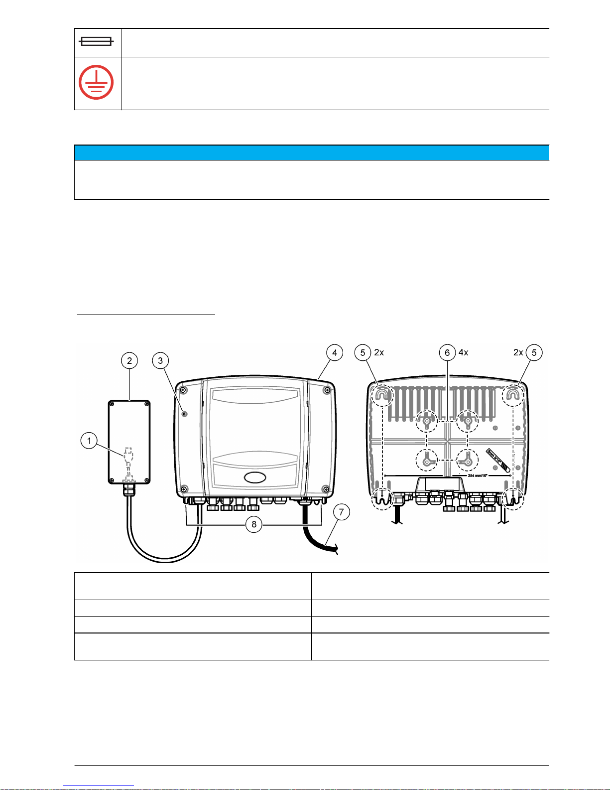
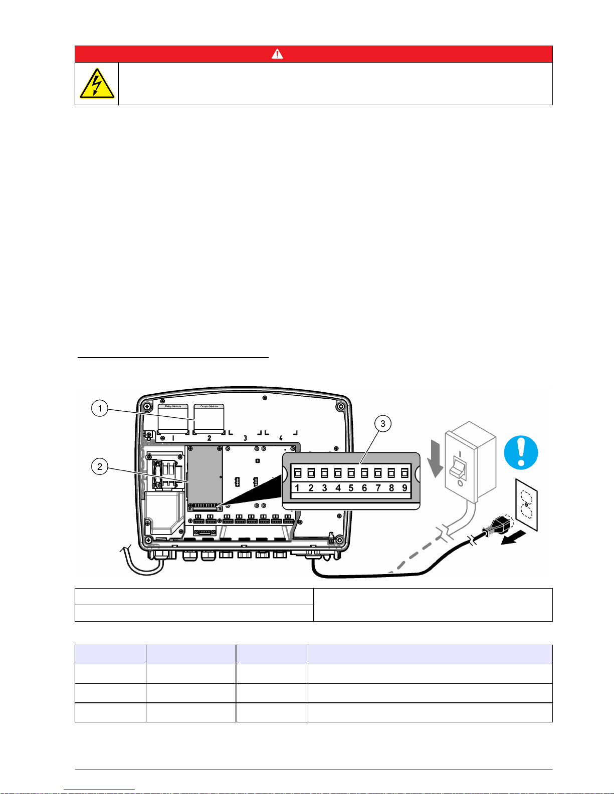
Figure 1 Product overview
1 USB connector (refer to Connect to a cellular
network on page 18)
5 Wall mounting slots
2 USB box 6 Pole mounting holes
3 Status indicator light (refer to Table 1) 7 Power cord (or conduit hub)
4 sc1500 controller 8 Electrical connectors and fittings (refer to Figure 6
on page 9)
English 5
Page 6
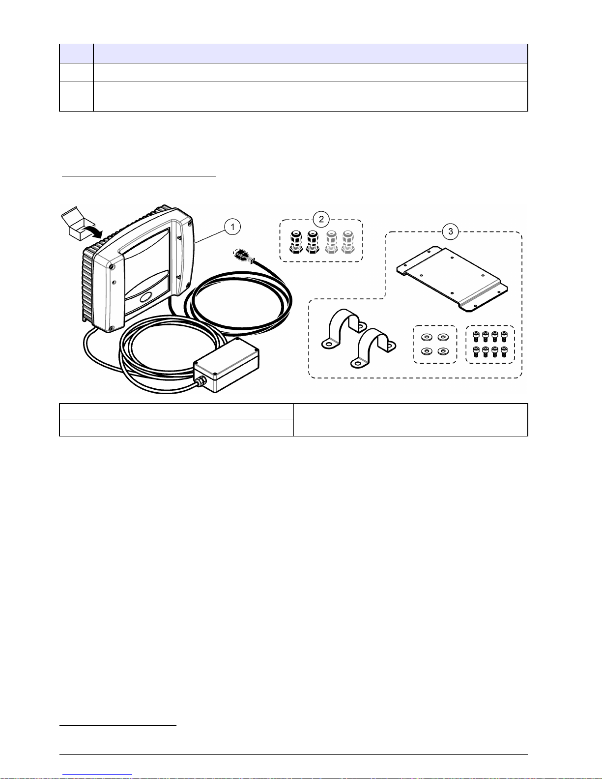
Table 1 Status indicator light
Color Status
Green Normal operation
Red There is a communications problem between the controller and one or more of the attached
measurement devices. Refer to Troubleshooting on page 21.
Product components
Make sure that all components have been received. Refer to Figure 2. If any items are missing or
damaged, contact the manufacturer or a sales representative immediately.
Figure 2 Product components
1 sc1500 controller 3 Pole mounting hardware for USB box
2
2 Strain relief fittings (quantity varies)
Installation
Mechanical installation
Install the controller
Attach the controller upright and level on a flat, vertical surface. Refer to the illustrated steps in
Figure 3. Install the controller in a location where the power disconnect device for the controller is
easily operated.
Mounting hardware is supplied by the user. Make sure that the wall mounting is able to hold 4 times
the weight of the equipment.
As an alternative, attach the instrument to a panel, vertical pole or horizontal pole. Refer to the
instruction sheet supplied with the optional mounting kit.
Note: The optional sunshield is recommended for all outdoor installations.
2
The pole mounting hardware is for a 40 mm (1.57 in.) diameter pole.
6 English
Page 7
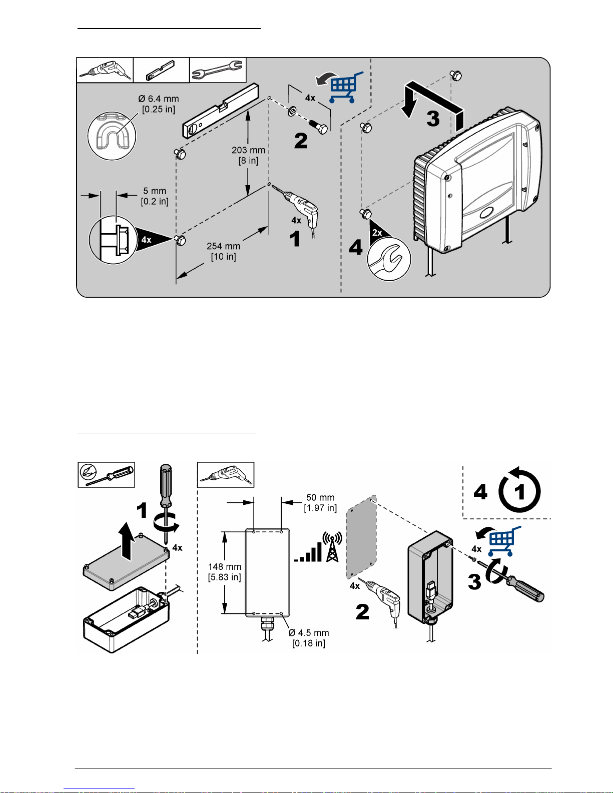
Figure 3 Wall mounting—controller
Install the USB box
Install the USB box in the location with the highest cellular signal strength. Use a mobile device with
the same cellular service provider as the sc1500 controller to find the location with the highest
cellular signal strength.
Install the USB box in a location where the power disconnect device for the controller is easily
operated.
Attach the USB box to a wall, vertical pole or horizontal pole. Refer to the illustrated steps in Figure 4
or Figure 5. Pole mounting hardware for a 40 mm (1.57 in.) pole is supplied with the instrument. Wall
mounting hardware is supplied by the user.
Figure 4 Wall mounting—USB box
English 7
Page 8
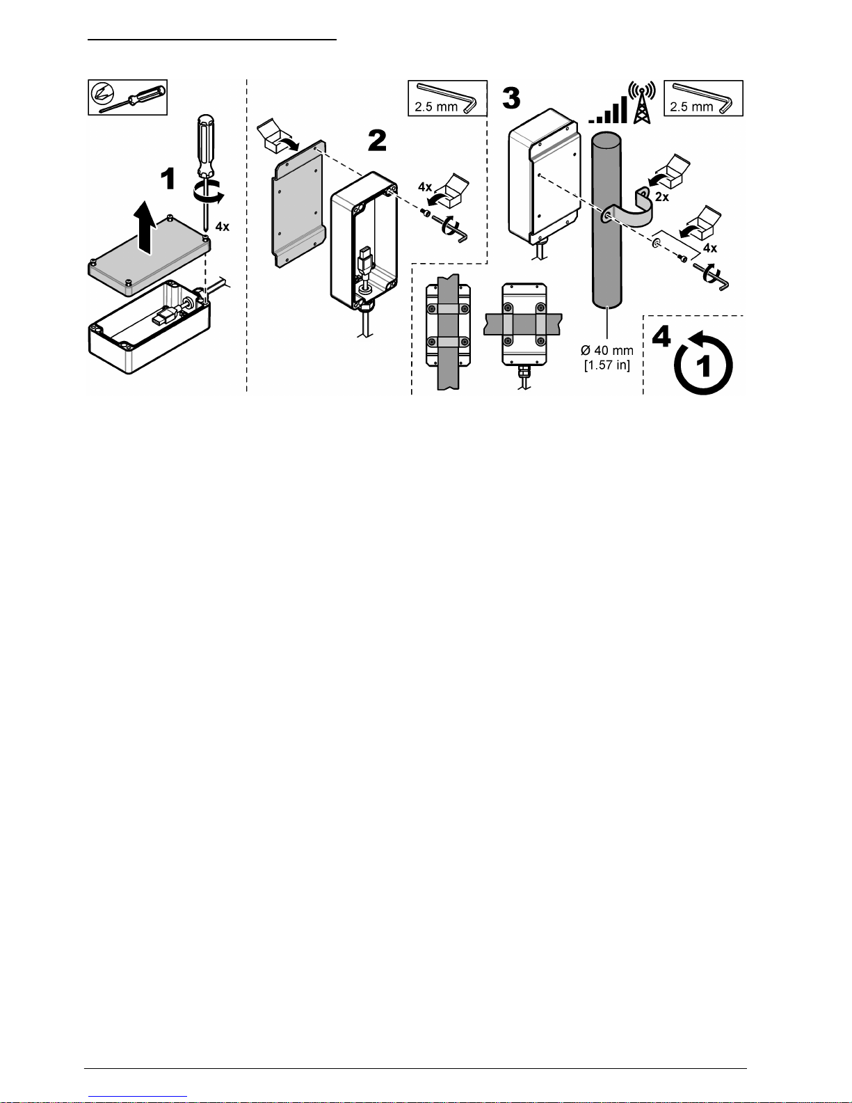
Figure 5 Pole mounting—USB box
Electrical installation
Electrical connectors and fittings
Figure 6 shows the electrical connectors and fittings on the instrument. Table 2 shows the connection
devices that can connect to the instrument. Only use the manufacturer-approved connection devices
from Table 2.
To keep the environmental rating of the enclosure, make sure that there is a plug in the strain relief
fittings that are not used and a connector cap on the unused connectors.
8
English
Page 9
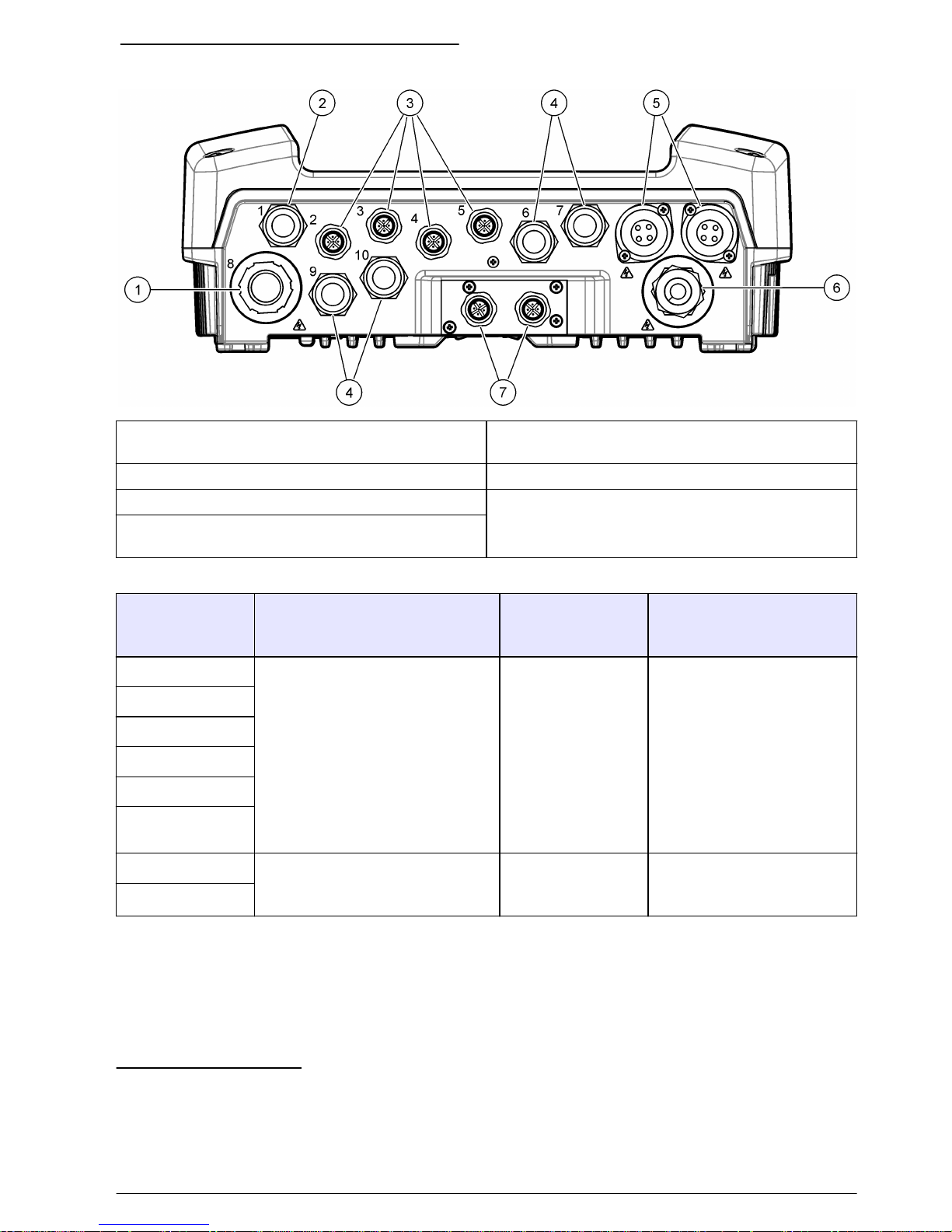
Figure 6 Electrical connectors and fittings
1 Large strain relief fitting for relay—2.19 mm conduit
or 9 to 13.5 mm diameter cable
5 AC power outlets
4
2 USB box cable 6 Power cord (or conduit hub)
3 Device connectors
3
7 Ethernet connectors
5
4 Strain relief fittings for the analog output card or for
the Profibus card—5 to 6 mm diameter cable
Table 2 Manufacturer-approved connection devices
Devices Description Power
consumption per
device
Controller connection
A/N-ISE sc For devices with low power
consumption: 60 W maximum total
consumption is permitted.
< 3.5 W Use the device connector.
Refer to Figure 6, item 3.
LDO sc
SOLITAX sc
NITRATAX sc
SONATAX sc
pHD (pH and
Redox)
AMTAX sc For devices with high power
consumption: 1000 VA maximum
total consumption is permitted.
< 500 W Use the AC power outlets.
Refer to Figure 6, item 5.
PHOSPHAX sc
3
The quantity of device connectors and strain relief fittings varies with model.
4
The AC power outlets only supply power when the instrument has the optional 100 to 240 VAC
power supply.
5
Right M12 connector used for MODBUS TCP/IP. Left M12 connector used to daisy chain
controllers. Refer to Modbus TCP/IP expansion on page 19.
English 9
Page 10
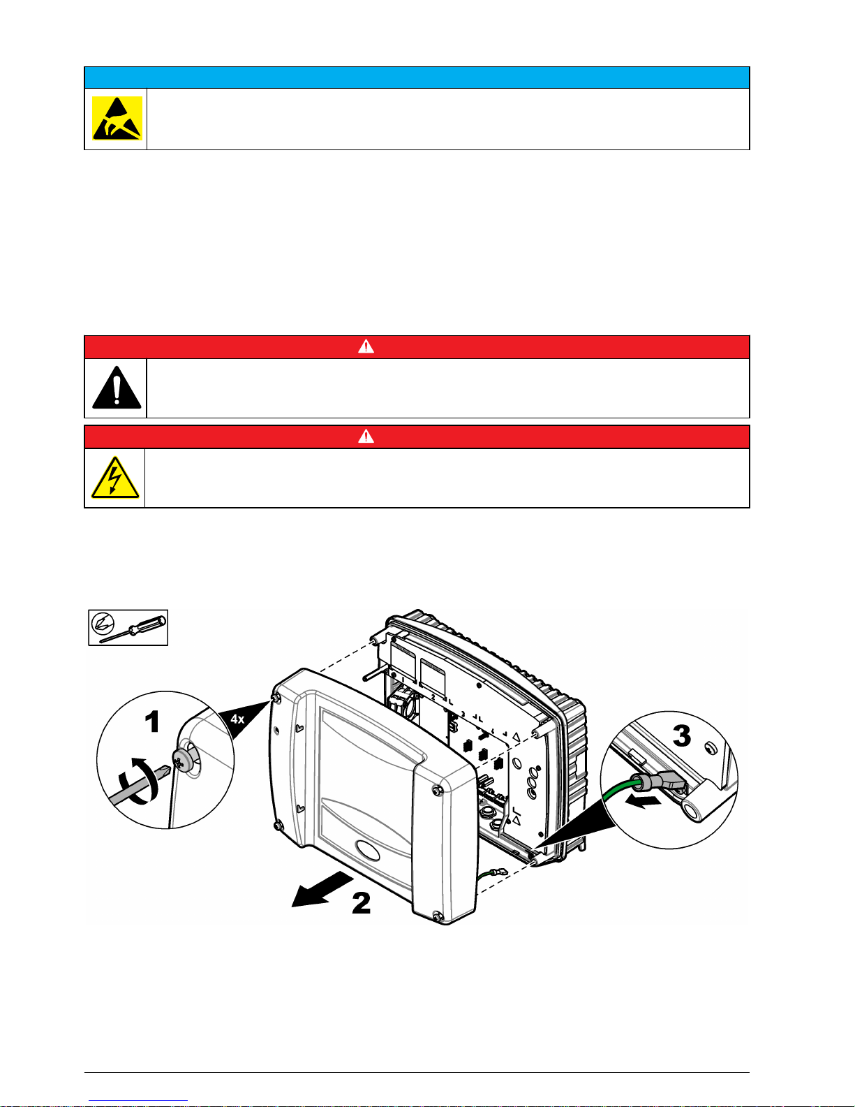
Electrostatic discharge (ESD) considerations
N O T I C E
Potential Instrument Damage. Delicate internal electronic components can be damaged by static
electricity, resulting in degraded performance or eventual failure.
Refer to the steps in this procedure to prevent ESD damage to the instrument:
• Touch an earth-grounded metal surface such as the chassis of an instrument, a metal conduit or
pipe to discharge static electricity from the body.
• Avoid excessive movement. Transport static-sensitive components in anti-static containers or
packages.
• Wear a wrist strap connected by a wire to earth ground.
• Work in a static-safe area with anti-static floor pads and work bench pads.
Power connections
D A N G E R
Multiple hazards. Only qualified personnel must conduct the tasks described in this section of the
document.
D A N G E R
Electrocution hazard. Always remove power to the instrument before making electrical connections.
If the controller does not have an installed power cord, connect power with conduit or a power cord.
Refer to the sections that follow to connect power with conduit or a power cord.
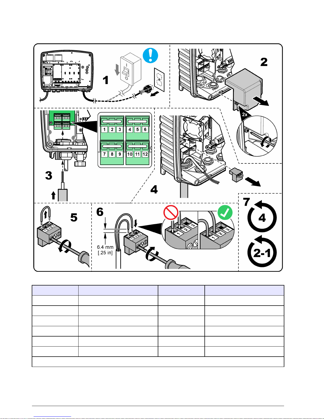
Remove the cover
Remove the cover as shown in the illustrated steps that follow.
High-voltage barrier
High-voltage wiring for the controller is located behind a high-voltage barrier in the controller
enclosure. Do not remove the barrier while power is supplied to the controller. Make sure that the
barrier is installed before power is supplied to the controller.
10
English
Page 11
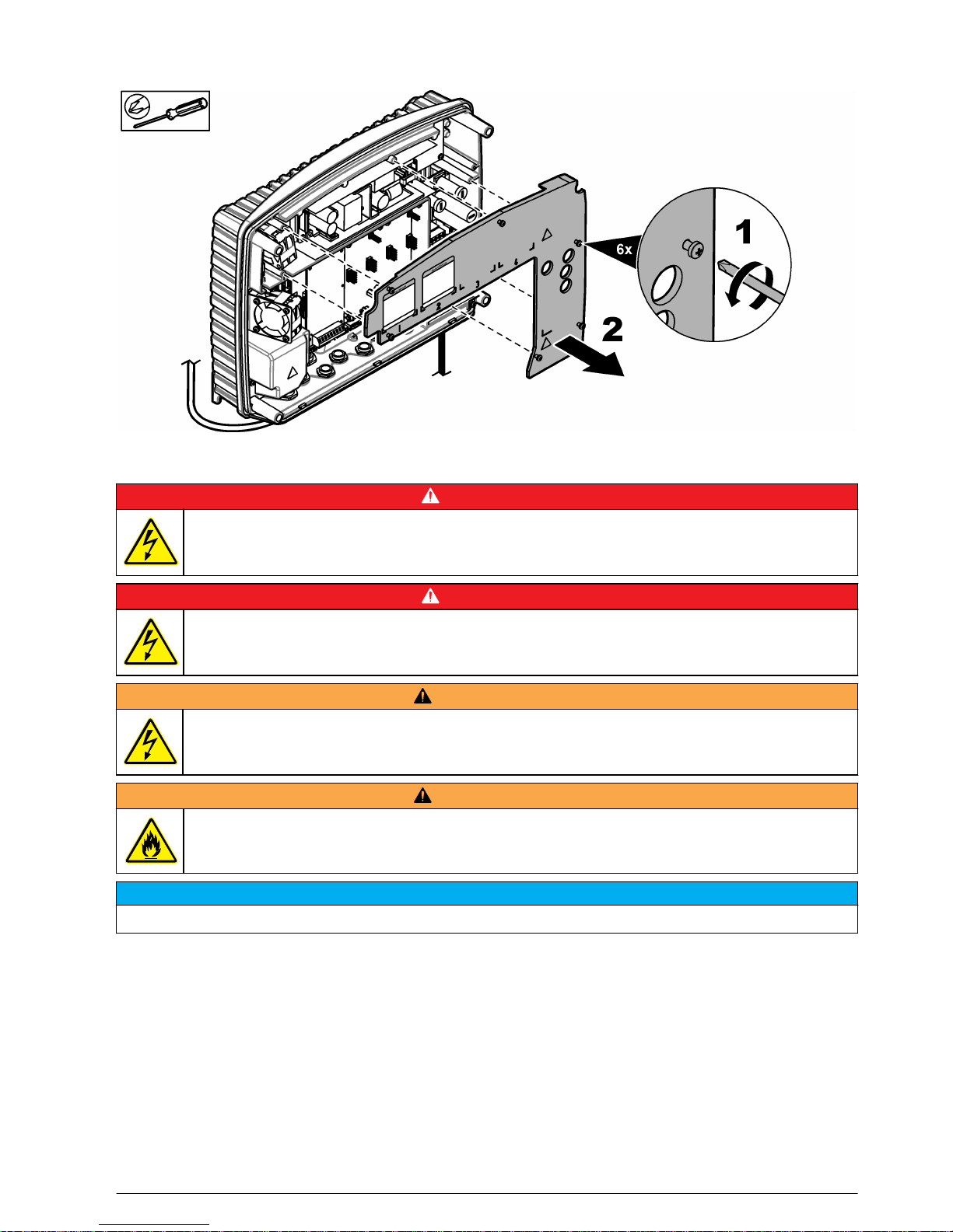
Remove the high-voltage barrier
Remove the high-voltage barrier as shown in the illustrated steps that follow.
Wiring for power
D A N G E R
Electrocution hazard. Protective Earth Ground (PE) connection is required.
D A N G E R
Electrical shock and fire hazards. Make sure to identify the local disconnect clearly for the conduit
installation.
W A R N I N G
Potential Electrocution Hazard. If this equipment is used outdoors or in potentially wet locations, a
Ground Fault Interrupt device must be used for connecting the equipment to its mains power source.
W A R N I N G
Electrical shock and fire hazards. Make sure that the user-supplied power cord and non‐locking plug
meet the applicable country code requirements.
N O T I C E
Install the device in a location and position that gives easy access to the disconnect device and its operation.
Supply power to the instrument with conduit or a power cable. Make sure that a circuit breaker with
sufficient current capacity is installed in the power line. The circuit breaker size is based on the wire
gauge used for installation.
For installation with conduit:
• Install a local disconnect for the instrument within 3 m (10 ft) of the instrument. Put a label on the
disconnect that identifies it as the main disconnect device for the instrument.
• Make sure that the power and safety ground service drops for the instrument are 1.5 mm2 (15
AWG) (and the wire insulation is rated for 300 VAC or higher and 70 °C (158 °F) minimum.
• Connect equipment in accordance with local, state or national electrical codes.
English
11
Page 12
• Connect the conduit through a conduit hub that holds the conduit securely and seals the enclosure
when tightened.
• If metal conduit is used, make sure that the conduit hub is tightened so that the conduit hub
connects the metal conduit to safety ground.
For installation with a power cable, make sure that the power cable is:
• Less than 3 m (10 ft) in length
• Rated sufficient for the supply voltage and current.
• Rated for at least 70 °C (158 °F) and applicable to the installation environment
• Not less than 1.5 mm2 (15 AWG) with applicable insulation colors for local code requirements
• A power cable with a three-prong plug (with ground connection) that is applicable to the supply
connection
• Connected through a cable gland (strain relief) that holds the power cable securely and seals the
enclosure when tightened
• Does not have a locking type device on the plug
Connect conduit or a power cord
The controller can be wired for line power by hard-wiring in conduit or wiring to a power cord.
Regardless of the wire used, the connections are made at the same terminals.
Refer to Figure 7 and Table 3 to connect conduit or a power cord. Insert each wire into the
appropriate terminal until the insulation is seated against the connector with no bare wire exposed.
Tug gently after insertion to make sure that there is a secure connection.
After the power connections are made, install the high-voltage barrier.
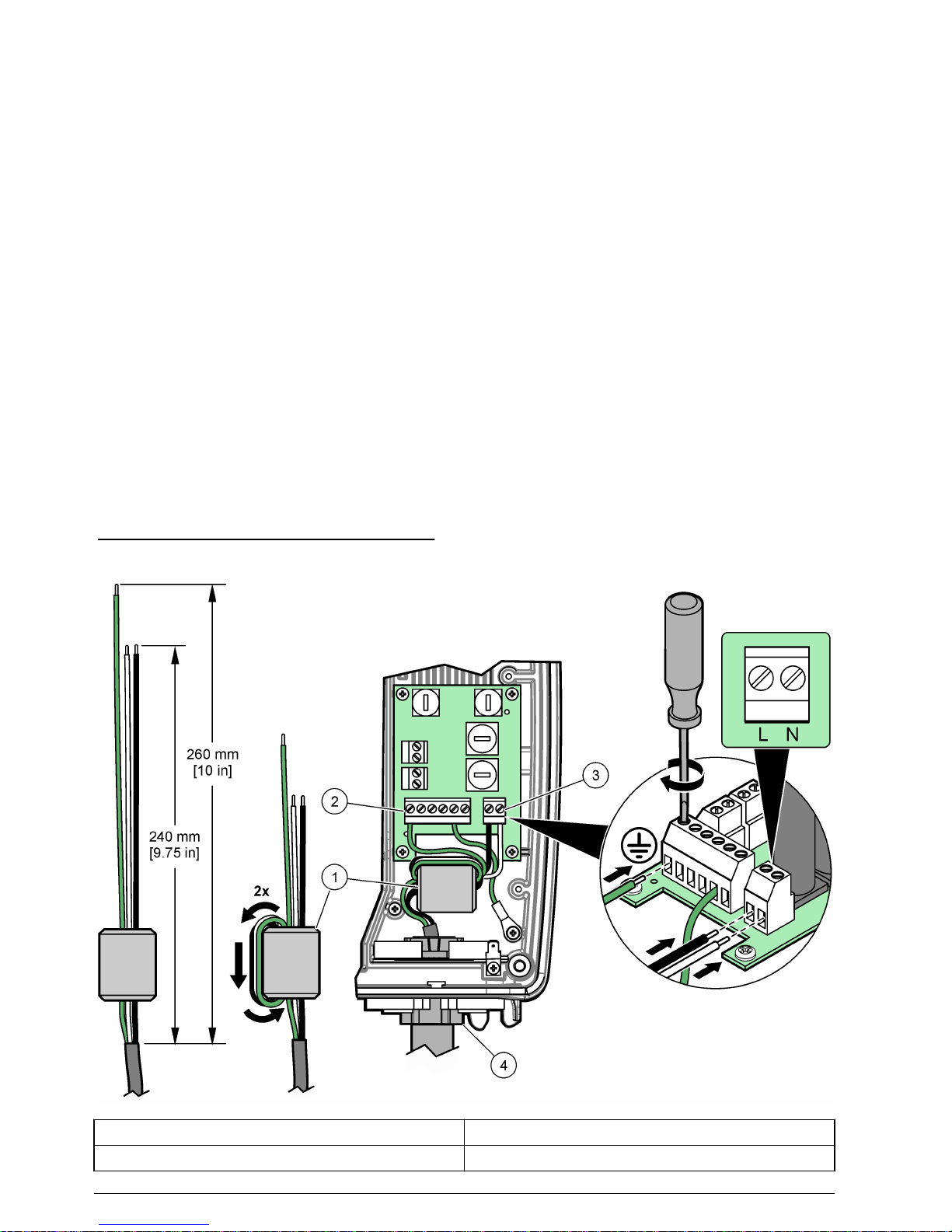
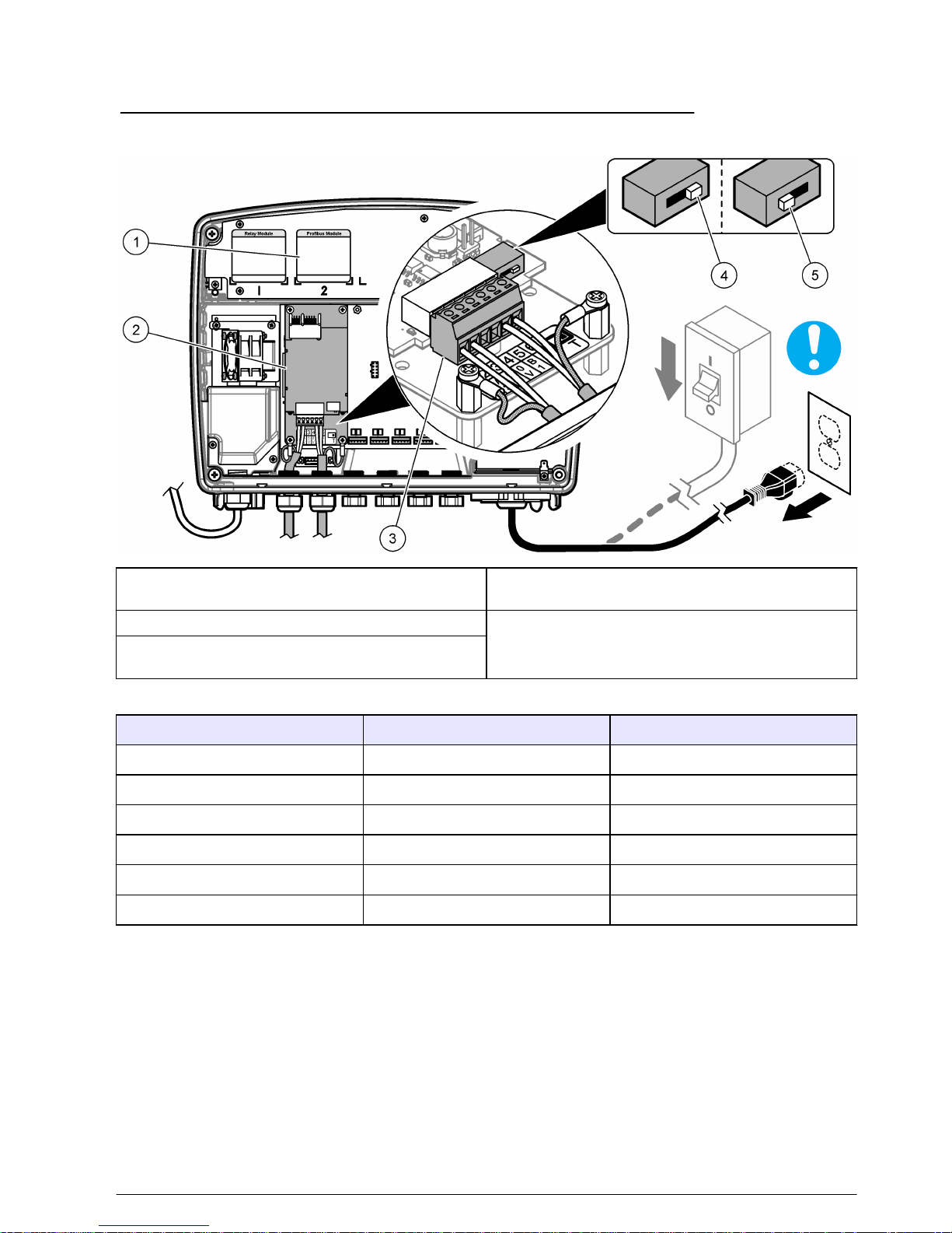
Figure 7 Connect conduit or a power cord
1 Ferrite core 3 AC power terminal
2 Protective earth ground terminal 4 Conduit hub (or strain relief fitting for power cord)
12 English
Page 13
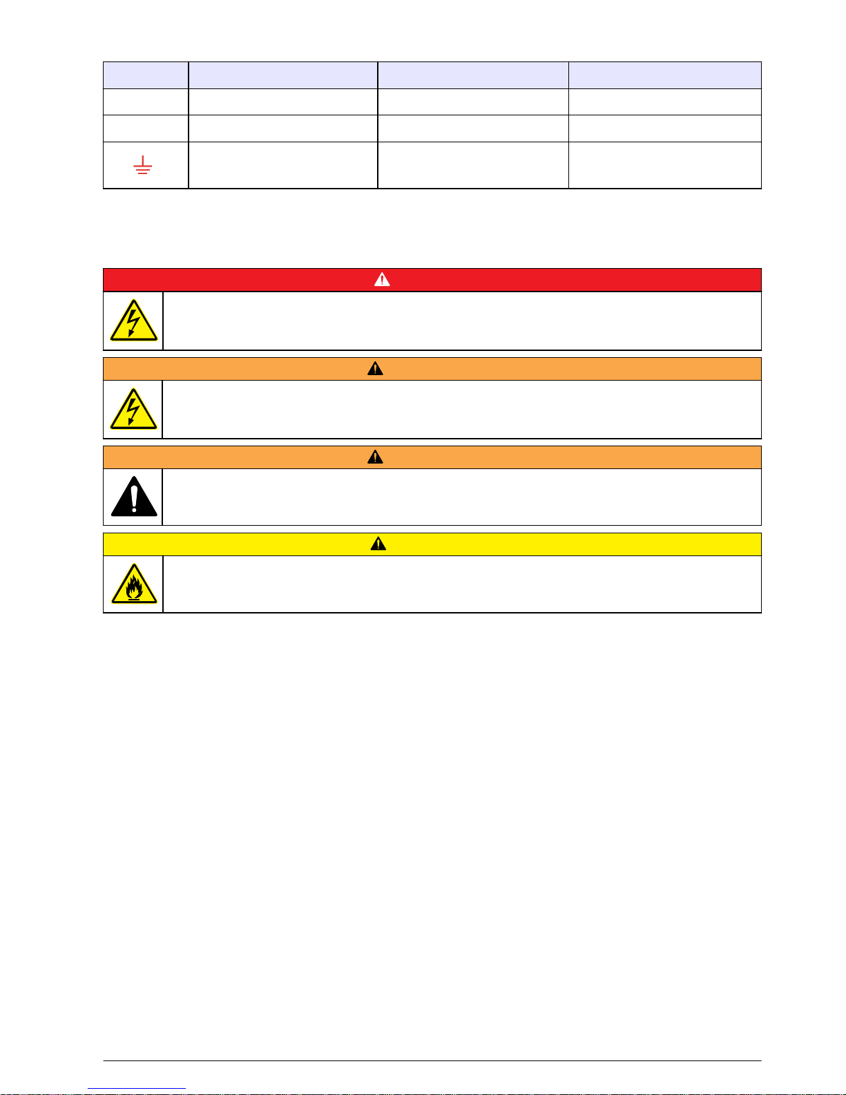
Table 3 Wiring information—AC power
Terminal Description Color—North America Color—EU
L Hot (L1) Black Brown
N Neutral (N) White Blue
Protective earth ground Green Green with yellow stripe
Expansion card connections
Connect the relays (optional)
D A N G E R
Electrocution hazard. Always remove power to the instrument before making electrical connections.
W A R N I N G
Potential Electrocution Hazard. Power and relay terminals are designed for only single wire termination.
Do not use more than one wire in each terminal.
W A R N I N G
Potential fire hazard. Do not daisy-chain the common relay connections or jumper wire from the mains
power connection inside the instrument.
C A U T I O N
Fire hazard. Relay loads must be resistive. Always limit current to the relays with an external fuse or
breaker. Obey the relay ratings in the Specifications section.
If the instrument has the optional relay card, the instrument has four non-powered, double-pole
relays. Each relay changes state when the selected trigger condition for the relay occurs.
The relay terminals are located behind a high-voltage barrier in the controller enclosure. Do not
remove the barrier while power is supplied to the relay terminals. Do not supply power to the relay
terminals when the barrier is not installed.
Connect each relay to a control device or an alarm device as necessary. Refer to the illustrated steps
that follow and Table 4 to connect the relays. Use the mobile application to select the trigger
condition for each relay.
Refer to Specifications on page 3 for the relay specifications. The relays are isolated from each other
and the low-voltage input/output circuitry.
The relay terminals accept 15 AWG wire (as determined by load application). Use wire with an
insulation rating of 300 VAC or higher. Wire gauge other than 15 AWG is not recommended.
The current to the relay contacts must be 5 A or less. Make sure to have a second switch available to
remove power from the relays locally in case of an emergency or for maintenance.
When switching large inductive loads (e.g., motors and pumps) or currents higher than 5 A, use an
auxiliary relay to extend the relay life.
Use the relays at either all high voltage (greater than 30 V-RMS and 42.2 V-PEAK or 60 VDC) or all
low voltage (less than 30 V-RMS and 42.2 V-PEAK, or less than 60 VDC). Do not configure a
combination of both high and low voltage.
English
13
Page 14
Relay terminal connections to the mains circuit in permanent connection applications must have
insulation rated for a minimum of 300 V, 70 °C (158 °F). Terminals connected to the mains circuit
with a power cord connection must be double insulated and rated 300 V, 70 °C (158 °F) at both the
inner and outer insulation levels.
Table 4 Wiring information—relays
Terminal Description Terminal Description
1 Relay 1, NC 7 Relay 3, NC
2 Relay 1, common 8 Relay 3, common
3 Relay 1, NO 9 Relay 3, NO
4 Relay 2, NC 10 Relay 4, NC
5 Relay 2, common 11 Relay 4, common
6 Relay 2, NO 12 Relay 4, NO
NC = normally closed; NO = normally open
14 English
Page 15
Connect the analog outputs (optional)
D A N G E R
Electrocution hazard. Always remove power to the instrument before making electrical connections.
If the instrument has the optional analog output card, the instrument has four 4–20 mA analog
outputs. Such outputs are commonly used for analog signaling or to control other external devices.
Connect each analog output to an external device as necessary. Refer to Figure 8 and Table 5 to
connect the analog outputs. Use the mobile application to configure each of the analog outputs to
agree with a measured parameter (e.g., pH or temperature).
Make connections with twisted-pair shielded wire and connect the shield to the shield terminal.
• Do not connect the shield at both ends of the cable.
• Use of non-shielded cable may result in radio frequency emission or susceptibility levels higher
than allowed.
• Maximum loop resistance is 500 Ω.
Notes:
• The analog output terminals accept 15 to 26 AWG wire.
• The analog outputs are isolated from the other electronics, but are not isolated from each other.
• The analog outputs are self-powered. Do not connect to a load with voltage that is independently
applied.
• The analog outputs cannot be used to supply power to a 2-wire (loop-powered) transmitter.
Figure 8 Connect the analog outputs
1 Wiring information—analog outputs 3 Analog output terminal
2 Analog output card
Table 5 Wiring information—analog outputs
Terminal Description Terminal Description
1 Output 1+ 6 Output 3–
2 Output 1– 7 Output 4+
3 Output 2+ 8 Output 4–
English 15
Page 16

Table 5 Wiring information—analog outputs (continued)
Terminal Description Terminal Description
4 Output 2– 9 Shield (connected to protective earth)
5 Output 3+
Connect the analog/digital inputs
D A N G E R
Electrocution hazard. Always remove power to the instrument before making electrical connections.
If the instrument has the optional input card, the instrument has four 4–20 mA inputs. Such inputs are
commonly used for looping in external devices' analog or digital signals.
Connect each external device to an input as necessary. Refer to Figure 9 to connect the inputs. Use
the mobile application to configure each of the inputs to agree with a measured parameter (e.g. flow).
Make connections with twisted-pair shielded wire and connect the shield to the shield terminal.
• Do not connect the shield at both ends of the cable.
• Use of non-shielded cable may result in radio frequency emission or susceptibility levels higher
than allowed.
Notes:
• The input terminals accept 15 to 26 AWG wire.
• The inputs are isolated from the other electronics, but are not isolated from each other.
Figure 9 Connect the inputs
1 Wiring information—inputs 3 Input terminal
2 Input card
For wiring information, refer to the SC1000 user manual, section 3.6.2 Input Card Connections.
Install the Profibus DP card
Refer to the applicable probe manual for operating instructions and instrument profiles. Refer to the
company web site for the latest GSD files and documentation.
To connect the Profibus DP card to the SC controller, refer to the SC controller Profibus
DP/V1 network card documentation. Install the Profibus card. Refer to Figure 10 and Table 6.
16
English
Page 17
After the plug-in expansion card is installed and connected, configure the card. Refer to the
documentation supplied with the Profibus DP card.
Figure 10 Profibus DP card (YAB103 since December 2013) connections
1 Wiring information—Profibus outputs 4 Network termination activated–last device on
network
2 Profibus DP card 5 Network termination deactivated–other devices on
network after this device
3 Terminal Block–Refer to Table 6 for terminal
assignments
Table 6 Profibus DP card (YAB103) terminal descriptions
Terminal Description Wire color
1 B2 out Red
2 A2 out Green
3 5 V Not used
4 0 V Not used
5 B1 in Red
6 A1 in Green
Remove an expansion card
Remove an expansion card if the probe connectors are blocked. Refer to the SC controller Profibus
DP/V1 network card documentation.
Note: The compact connectors are a very tight fit and the connections can easily break. Do not apply too much
force to remove the compact connectors.
1. Delete the card in the SC controller.
2. Remove power from the instrument.
3. Remove the probe module cover. Refer to Remove the cover on page 10
4. Disconnect all of the wires from the card.
English
17
Page 18
5. Remove the screws on the card.
6. Remove the card.
To replace and configure the card, provide the Profibus DP address and the cyclic Profibus DP
telegram to a Hach service technician.
Install the cover
Connect the ground wire for the cover to the controller, then install the instrument cover. Refer to
Remove the cover on page 10.
Make sure that the cover screws are tight to keep the environmental rating.
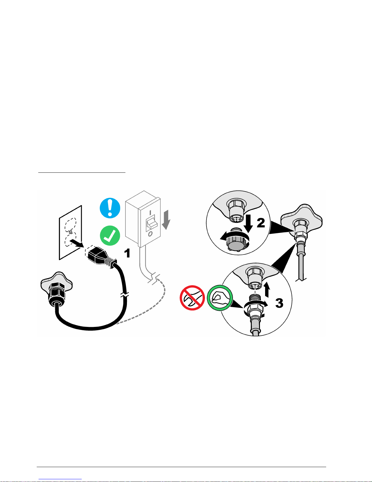
Connect measurement devices
Connect digital devices (e.g., sensors and analyzers) to the device connectors on the instrument.
Refer to Figure 11. Keep the device connector caps for future use.
Make sure that the device cables do not cause a trip hazard and do not have sharp bends.
If a measurement device has two cables, connect the second cable to an AC power outlet on the
instrument. Refer to Figure 6 on page 9. The voltage and current available at the AC power outlets is
the same as the power supplied to the instrument. Make sure that the power supplied is within the
power requirements of the device.
Note: The AC power outlets only supply power when the instrument has the optional 100 to 240 VAC power supply.
Figure 11 Connect a device
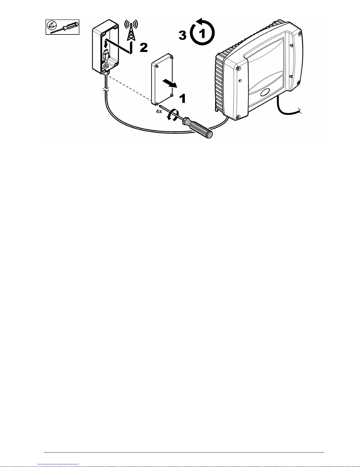
Connect to a cellular network
Connect the instrument to a cellular network with the USB connector in the USB box. Refer to the
illustrated steps that follow.
After the cover is installed, make sure that the screws are tight to keep the environmental rating.
18
English
Page 19
Modbus TCP/IP expansion
Modbus TCP/IP is a standard for industrial communications. The Modbus TCP/IP protocol connects
computers to measurement and control systems that use the TCP/IP protocol for data transmission.
This type of data transmission is known as machine to machine (M2M) communication.
The Modbus TCP/IP software module enables the controller to be integrated directly in
programmable logic controller (PLC) systems. PLC systems record and process the controller
measured data. The data analysis and the procedures caused by the results are programmed in the
PLC system.
Note: To use the Modbus TCP/IP software module, make sure that there is no Modbus card installed on the
controller.
Connect the controller to the external USB box. Refer to the documentation supplied with the USB
box. It is possible to daisy chain controllers. Refer to Figure 12. When a modem or WiFi stick is
connected at the USB box, this channel connects the controller to the internet. Thus, it is not possible
to connect the controller with the modem to the internet and to operate Modbus TCP with WiFi at the
same time; the USB box has only one USB slot. In such situation, Modbus TCP/IP can only operate
with the ethernet LAN connector (ethernet M12 connector). Table 7 shows the Internet and Modbus
TCP/IP possible connections combinations.
When only one controller is used, only the right M12 connector is used to connect to the PLC/internet
(left connector is not used). When daisy chain is used, always connect the right M12 connector with
the left M12 connector of the next controller. The daisy chained controller connected to PLC/internet
uses the right M12 connector for PLC/internet connection.
English
19
Page 20
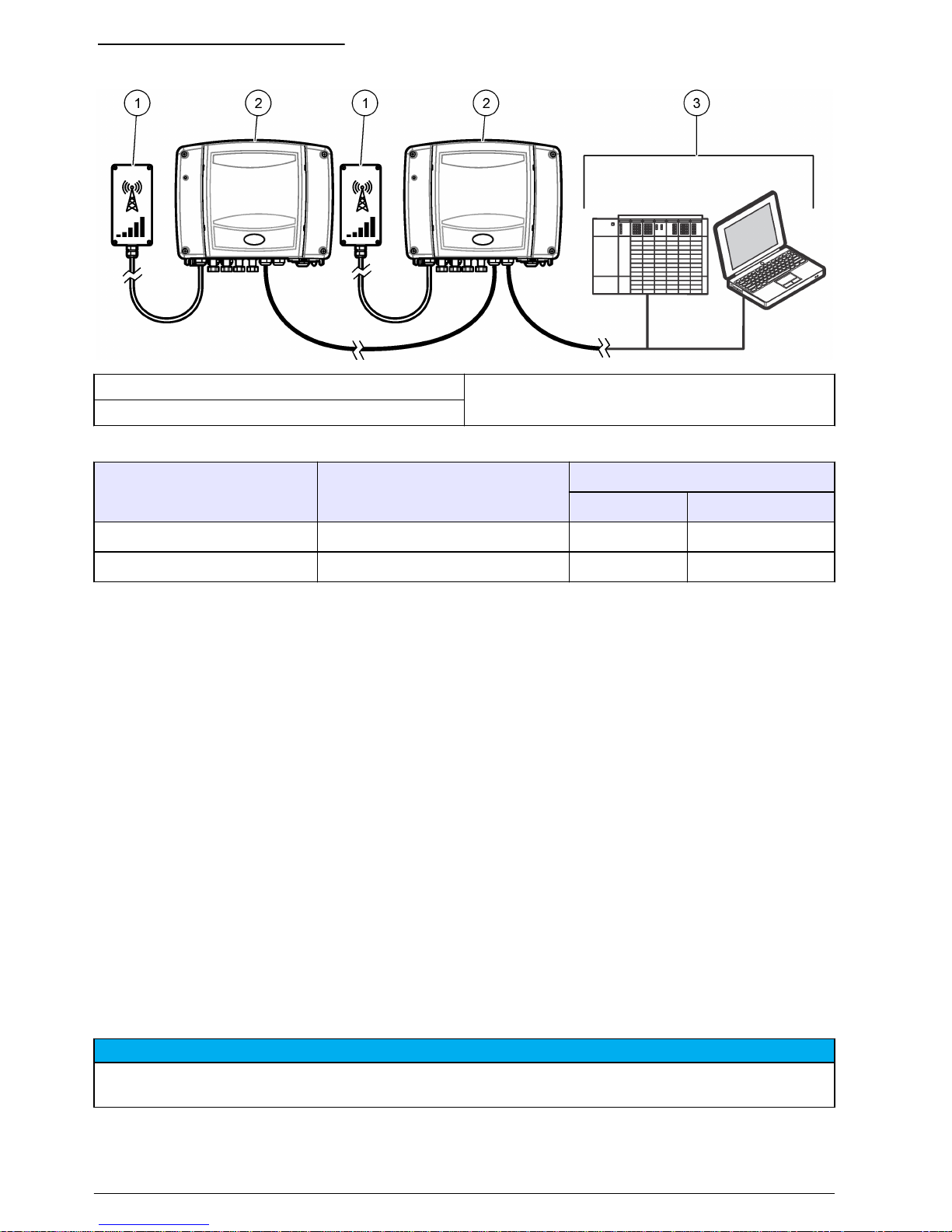
Figure 12 Connection diagram
1 USB Box 3 PLC system
2 Controller
Table 7 Internet and Modbus TCP/IP connections combinations
LAN (M12 socket)
USB Box
WiFi Modem
Internet X X X
Modbus TCP/IP X X —
Startup
Connect the power cord to an electrical outlet with protective earth ground or set the circuit breaker
for the controller to on.
Operation
Use the MSM software to interact with the connected measurement devices. Contact Hach Technical
Support to get a Claros Mobile Sensor Management account for the first time.
Note: Refer to the manufacturer's website to find more information about the MSM software.
1. Open an internet browser, then enter the correct URL:
• US: https://us.fsn.hach.com
• EU: https://eu.fsn.hach.com
2. Enter login information to:
• Receive the status and measurement information about measurement devices.
• Configure and calibrate measurement devices.
• Get access to interactive, step-by-step maintenance guides.
Maintenance
N O T I C E
Do not disassemble the instrument for maintenance. If the internal components must be cleaned or repaired,
contact the manufacturer.
20 English
Page 21
Clean the instrument
Clean the exterior of the instrument with a moist cloth and a mild soap solution and then wipe the
instrument dry as necessary.
Fuse replacement
The fuse is a not a user-serviceable item. Contact technical support. A blown fuse can be an
indication that the instrument has a problem and that service is necessary.
Prepare for storage or shipping
Before long-term storage or shipping, prepare the controller as follows:
1. Use the mobile application to save all the important data on the controller to a storage device.
Note: All the factory and user settings are saved on the I/O cards in the controller.
2. Remove power to the controller.
3. Disconnect all the external devices that are connected to the controller.
4. Remove the USB box from the wall or pole.
5. Remove the controller from the wall, panel or pole.
6. Put the controller and USB box in a protective film or dry cloth. Keep the controller and USB box
in a dry location.
Troubleshooting
Problem Possible cause Solution
The status indicator
light flashes red.
There is a communication failure
between the controller and one or
more of the attached measurement
devices.
Make sure that the measurement device is
connected to the controller.
Damage has occurred to an attached
measurement device or the device
cable.
Examine the measurement device and the device
cable for damage. Make sure that the
measurement device is operational. If damage is
found, contact technical support.
The status indicator
light is off.
Power is not supplied to the controller
or there is a blown fuse.
Make sure that there is power to the controller.
If there is power, remove power to the controller
and identify if there is a blown fuse. If a blown fuse
is found, contact technical support.
Accessories
Note: Product and Article numbers may vary for some selling regions. Contact the appropriate distributor or refer to
the company website for contact information.
Description Item no.
GSM modem kit LZY971
Wi-Fi adapter US LZY996
Wi-Fi adapter EU LZY997
Panel mounting kit, sc1500, includes:
Bracket, strain relief fitting and digital extension cable
6169900
Pole mounting kit with sunshield, sc1500, includes:
Sunshield, ground base, pole, screw set and mounting plate
LZX957
English 21
Page 22
Accessories (continued)
Description Item no.
Wall mounting kit with sunshield, includes:
Sunshield, bracket, bolts (4x), nuts (4x) and washers (4x)
LZX958
Pole mounting hardware for sunshield, includes:
Mounting feet (8x), screws (4x), bolts (12x), washers (8x), nuts (4x) and anchors (4x)
LZX948
Power cable, China LZY393
Power cable, Great Britain LZY394
Power cable, European Union LZY395
Power cable, United States LZY396
Digital extension cable, measurement device, 10 m (32.8 ft) LZX849
Digital extension cable, measurement device, 20 m (65.6 ft) LZX851
22 English
Page 23

Table des matières
Caractéristiques à la page 23 Fonctionnement à la page 42
Généralités à la page 24 Maintenance à la page 42
Installation à la page 27 Dépannage à la page 43
Mise en marche à la page 42 Accessoires à la page 43
Caractéristiques
Les caractéristiques techniques peuvent être modifiées sans préavis.
Caractéristique Détails
Dimensions (l x P x H) Transmetteur : 315 x 120 x 242 mm (12,28 x 4,68 x 9,5 po)
Boîtier USB : 79,5 x 55,1 x 159,5 mm (3,13 x 2,17 x 6,28 po)
Boîtier Transmetteur : métal avec surface résistance à la corrosion, classification
NEMA 4X/IP65
Boîtier USB : ABS/polycarbonate, classification NEMA 4X/IP65
Poids Environ 5 kg (11 livres). Le poids varie en fonction des modèles.
Niveau de pollution 2
Catégorie de surtension II
Classe de protection I
Alimentation requise 100 à 240 V CA ± 10 V CA, 50/60 Hz, 1000 VA maximum
Fusible F1 et F2 : M 3,5 A L, 250 V ou T 3,15 A L, 250 V ; F3 et F4 : T 8 A H, 250 V
Température de fonctionnement -20 à 55 °C (-4 à 131 °F)
Température de stockage -20 à 70 °C (–4 à 158 °F)
Humidité 95 % d'humidité relative, sans condensation
Altitude 2000 m (6561 pieds)
Connexions d'un appareil de
mesure
Deux, quatre ou six connecteurs d'appareil et deux prises d'alimentation CA
1
Connexions réseau Deux connecteurs Ethernet (10/100 Mbit/s), fonction de commutation,
connecteur M12 femelle code D
Un connecteur USB dans un boîtier USB
Carte de relais (en option) Quatre relais sur chaque carte de relais, contacts inverseurs (SPDT)
Tension par découpage maximale : 250 V c.a., 125 V c.c.
Courant maximal de commutation : 5 A
Remarque : Veillez à installer le disjoncteur externe 5 A.
Puissance maximum de commutation : 1 500 VA, 250 V CA, 625 W, 125 V
CC
Calibre de fil : 1,5 mm2 (15 AWG) maximum
Carte de sortie analogique (en
option)
Quatre sorties analogiques 4-20 mA sur chaque carte de sortie analogique,
500 Ω maximum
Section de fil : 1,5 mm2 (15 AWG) maximum
Le fabricant recommande d'utiliser des câbles de signal blindés.
1
Les prises d'alimentation CA n'alimentent l'instrument que si l'alimentation facultative de 100 à
240 V CA est installée.
Français 23
Page 24
Caractéristique Détails
Certification Compatible cTUVus, compatible CE, protection contre surtensions DIN EN
61326
Garantie 1 an (UE : 2 ans)
Généralités
En aucun cas le constructeur ne saurait être responsable des dommages directs, indirects, spéciaux,
accessoires ou consécutifs résultant d'un défaut ou d'une omission dans ce manuel. Le constructeur
se réserve le droit d'apporter des modifications à ce manuel et aux produits décrits à tout moment,
sans avertissement ni obligation. Les éditions révisées se trouvent sur le site Internet du fabricant.
Consignes de sécurité
A V I S
Le fabricant décline toute responsabilité quant aux dégâts liés à une application ou un usage inappropriés de ce
produit, y compris, sans toutefois s'y limiter, des dommages directs ou indirects, ainsi que des dommages
consécutifs, et rejette toute responsabilité quant à ces dommages dans la mesure où la loi applicable le permet.
L'utilisateur est seul responsable de la vérification des risques d'application critiques et de la mise en place de
mécanismes de protection des processus en cas de défaillance de l'équipement.
Veuillez lire l'ensemble du manuel avant le déballage, la configuration ou la mise en fonctionnement
de cet appareil. Respectez toutes les déclarations de prudence et d'attention. Le non-respect de
cette procédure peut conduire à des blessures graves de l'opérateur ou à des dégâts sur le matériel.
Assurez-vous que la protection fournie avec cet appareil n'est pas défaillante. N'utilisez ni n'installez
cet appareil d'une façon différente de celle décrite dans ce manuel.
Interprétation des indications de risques
D A N G E R
Indique une situation de danger potentiel ou imminent qui entraînera la mort ou de graves blessures si elle n'est
pas évitée.
A V E R T I S S E M E N T
Indique une situation de danger potentiel ou imminent qui peut entraîner la mort ou de graves blessures si elle
n'est pas évitée.
A T T E N T I O N
Indique une situation de danger potentiel qui peut entraîner des blessures mineures ou modérées.
A V I S
Indique une situation qui, si elle n'est pas évitée, peut occasionner l'endommagement du matériel. Informations
qui doivent être soulignées.
Étiquettes de mise en garde
Lisez toutes les informations et toutes les étiquettes apposées sur l’appareil. Des personnes peuvent
se blesser et le matériel peut être endommagé si ces instructions ne sont pas respectées. Tout
symbole sur l'appareil renvoie à une instruction de mise en garde dans le manuel.
Ceci est le symbole d'alerte de sécurité. Respectez tous les messages de sécurité qui suivent ce
symbole afin d'éviter tout risque de blessure. S'ils sont apposés sur l'appareil, se référer au manuel
d'utilisation pour connaître le fonctionnement ou les informations de sécurité.
Ce symbole indique qu'il existe un risque de choc électrique et/ou d'électrocution.
24 Français
Page 25
Ce symbole indique la présence d'appareils sensibles aux décharges électrostatiques et indique que
des précautions doivent être prises afin d'éviter d'endommager l'équipement.
Le matériel électrique portant ce symbole ne doit pas être mis au rebut dans les réseaux domestiques
ou publics européens. Retournez le matériel usé ou en fin de vie au fabricant pour une mise au rebut
sans frais pour l'utilisateur.
Ce symbole, s'il figure sur le produit, indique l’emplacement d’un fusible ou d'un dispositif limiteur de
courant.
Ce symbole indique que l'élément marqué nécessite une connexion de protection à la terre. Si
l'appareil n'est pas fourni avec une mise à la terre sur un cordon, effectuez la mise à la terre de
protection sur la borne de conducteur de protection.
Présentation du produit
A V I S
La sécurité du réseau et du point d'accès relève de la responsabilité du client utilisant l'appareil sans fil. Le
fabricant ne peut être tenu pour responsable des dommages, y compris mais sans s'y limiter, indirects,
particuliers, fortuits ou accessoires occasionnés en raison d'une brèche dans la sécurité du réseau ou d'une
violation de la sécurité du réseau.
Le transmetteur sc1500 est destiné aux appareils d'analyse numérique, tels que les capteurs et les
analyseurs. Reportez-vous à la section Figure 1.
Le transmetteur est disponible avec des relais et des sorties analogiques en option (4-20 mA). Les
relais en option permettent de contrôler les appareils externes (p. ex., contrôle des appareils et des
appareils d'alarme). Les sorties analogiques servent à transmettre les mesures aux appareils
externes.
Le transmetteur est configuré et piloté par une application mobile sur un appareil iOS® ou Android
®
fourni par le client et disposant d'un navigateur Internet et d'une connexion à Internet. Le
transmetteur communique sur un réseau local (LAN), Wi-Fi ou cellulaire.
Français
25
Page 26
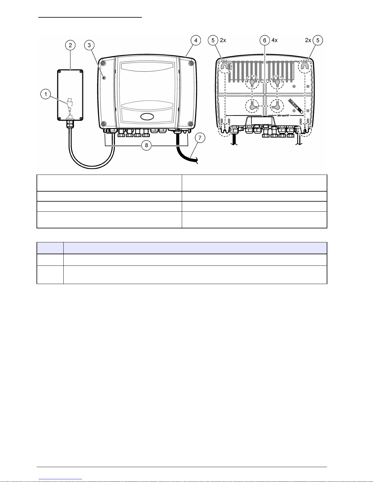
Figure 1 Présentation du produit
1 Connecteur USB (reportez-vous à Connexion à un
réseau cellulaire à la page 40)
5 Patte de fixation pour montage mural
2 Boîtier USB 6 Trous pour montage sur poteau
3 Voyant d'état (reportez-vous à Tableau 1) 7 Cordon d'alimentation (ou raccord de conduite)
4 Transmetteur sc1500 8 Connecteurs électriques et fixations (reportez-vous
à Figure 6 à la page 30)
Tableau 1 Voyant d'état
Couleur Etat
Vert Fonctionnement normal
Rouge Un problème de communication s'est produit entre le transmetteur et au moins l'un des appareils de
mesure connectés. Reportez-vous à la section Dépannage à la page 43.
Composants du produit
Assurez-vous d'avoir bien reçu tous les composants. Reportez-vous à la section Figure 2. Si des
éléments manquent ou sont endommagés, contactez immédiatement le fabricant ou un représentant
commercial.
26
Français
Page 27

Figure 2 Composants du produit
1 Transmetteur sc1500 3 Accessoires de montage sur poteau pour le boîtier
USB
2
2 Fixation avec protecteur de cordon (quantité
variable)
Installation
Installation mécanique
Installation du transmetteur
Fixez le transmetteur à la verticale et alignez-le sur une surface plane verticale. Reportez-vous aux
procédures présentées à la Figure 3. Installez le transmetteur à un endroit où le dispositif de
sectionnement du transmetteur est facilement accessible.
La visserie de montage est fournie par l'utilisateur. Vérifiez que le montage mural est capable de
supporter 4 fois le poids de l'équipement.
Sinon, fixez l'instrument sur un panneau, un poteau vertical ou horizontal. Reportez-vous à la feuille
d'instructions fournie avec le kit de montage en option.
Remarque : Le pare-soleil est facultatif, mais recommandé, pour toutes les installations extérieures.
2
Les accessoires sont destinés au montage sur un poteau de 40 mm (1,57 po) de diamètre.
Français 27
Page 28

Figure 3 Montage mural : transmetteur
Installation du boîtier USB
Installez le boîtier USB à un emplacement où le signal cellulaire est aussi fort que possible. Utilisez
un appareil mobile avec le même fournisseur de service cellulaire que le transmetteur sc1500 pour
identifier l'emplacement ayant la plus forte puissance cellulaire.
Installez le boîtier USB à un endroit où le dispositif de sectionnement du transmetteur est facilement
accessible.
Fixez le boîtier USB sur un mur, ou sur un poteau vertical ou horizontal. Reportez-vous aux
procédures illustrées dans la Figure 4 ou la Figure 5. Les accessoires de montage pour un poteau de
40 mm (1,57 po) sont fournis avec l'instrument. Le matériel de montage mural est fourni par
l'utilisateur.
Figure 4 Montage mural : boîtier USB
28 Français
Page 29

Figure 5 Montage sur poteau : boîtier USB
Installation électrique
Connecteurs électriques et fixations
La section Figure 6 illustre les connecteurs électriques et les fixations de l'instrument. La section
Tableau 2 montre les appareils de raccordement compatibles avec l'instrument. Utilisez uniquement
les appareils agréés par le fabricant indiqués dans le Tableau 2.
Afin d'assurer la classification environnementale du boîtier, assurez-vous que les fixations avec
protecteur de cordon qui ne sont pas utilisées soient bouchées et que les connecteurs inutilisés sont
protégés par un capot.
Français
29
Page 30

Figure 6 Connecteurs électriques et fixations
1 Connecteur large pour relais : conduite de 2,19 mm
ou câble de diamètre 9 à 13,5 mm
5 Prises d'alimentation CA
4
2 Câble du boîtier USB 6 Cordon d'alimentation (ou raccord de conduite)
3 Connecteurs d'appareil
3
7 Connecteurs Ethernet
5
4 Fixations avec protecteur de cordon pour la carte de
sortie analogique ou pour la carte Profibus, câble de
5 à 6 mm de diamètre
Tableau 2 Appareils de raccordement agréés par le fabricant
Appareils Description Consommation
électrique par
appareil
Raccordement au
transmetteur
A/N-ISE sc Pour les appareils à faible
consommation électrique, une
consommation totale de 60 W est
autorisée.
< 3,5 W Utilisez le connecteur de
l'appareil. Reportez-vous à la
Figure 6, repère 3.
LDO sc
SOLITAX sc
NITRATAX sc
SONATAX sc
pHD (pH et
Redox)
AMTAX sc Pour les appareils à faible
consommation électrique, une
consommation totale de 1 000 VA
est autorisée.
< 500 W Utilisez les sorties d'alimentation
secteur. Reportez-vous à la
Figure 6, repère 5.
PHOSPHAX sc
3
Le nombre de connecteurs d'appareil et de fixations avec protecteur de cordon varie en fonction
du modèle.
4
Les prises d'alimentation CA n'alimentent l'instrument que si l'alimentation facultative de 100 à
240 V CA est installée.
5
Connecteur M12 droit utilisé pour MODBUS TCP/IP. Connecteur M12 gauche utilisé pour la
connexion en guirlande des contrôleurs. Reportez-vous à la Extension Modbus TCP/IP
à la page 41.
30 Français
Page 31

Remarques relatives aux décharges électrostatiques (ESD)
A V I S
Dégât potentiel sur l'appareil Les composants électroniques internes de l'appareil peuvent être
endommagés par l'électricité statique, qui risque d'altérer ses performances et son fonctionnement.
Reportez-vous aux étapes décrites dans cette procédure pour éviter d'endommager l'appareil par
des décharges électrostatiques.
• Touchez une surface métallique reliée à la terre (par exemple, le châssis d'un appareil, un conduit
ou un tuyau métallique) pour décharger l'électricité statique de votre corps.
• Evitez tout mouvement excessif. Transportez les composants sensibles à l'électricité statique dans
des conteneurs ou des emballages antistatiques.
• Portez un bracelet spécial relié à la terre par un fil.
• Travaillez dans une zone à protection antistatique avec des tapis de sol et des sous-mains
antistatiques.
Branchements électriques
D A N G E R
Dangers multiples. Seul le personnel qualifié doit effectuer les tâches détaillées dans cette section du
document.
D A N G E R
Risque d'électrocution. Débranchez systématiquement l'alimentation de l'appareil avant d'effectuer
toute connexion électrique.
Si le transmetteur n'est pas fourni avec un cordon d'alimentation, utilisez une conduite ou un câble
d'alimentation pour le raccorder au secteur. Reportez-vous aux sections suivantes pour connecter
l'alimentation avec une conduite ou un câble d'alimentation.
Retrait du panneau
Retirez le panneau comme indiqué sur les étapes illustrées ci-dessous.
Français
31
Page 32

Barrière de protection haute tension
Les câbles haute tension du transmetteur sont situés derrière la barrière haute tension, dans le
boîtier du transmetteur. Ne retirez pas l'écran lorsque le transmetteur est sous tension. Assurez-vous
que l'écran est installé avant de mettre le transmetteur sous tension.
Retrait de l'écran de protection contre les hautes tensions
Retirez l'écran de protection contre les hautes tensions comme indiqué dans les étapes illustrées cidessous.
Câblage pour l'alimentation
D A N G E R
Risque d'électrocution. Un raccordement à la terre est nécessaire.
D A N G E R
Risques de choc électrique et d'incendie. Assurez-vous d'identifier clairement l'emplacement du
dispositif de déconnexion local pour l'installation du conduit.
A V E R T I S S E M E N T
Risque potentiel d'électrocution Si cet équipement est utilisé à l'extérieur ou dans des lieux
potentiellement humides, un dispositif de disjoncteur de fuite à la terre doit être utilisé pour le
branchement de l'équipement à sa source d'alimentation secteur.
A V E R T I S S E M E N T
Risques de choc électrique et d'incendie. Assurez-vous que le cordon et la fiche non verrouillable
fournis par l'utilisateur sont conformes aux normes du pays concerné.
A V I S
Installez l'appareil dans un emplacement et une position permettant d'accéder facilement à l'appareil débranché
et à son fonctionnement.
Alimentez l'instrument avec une conduite ou un câble d'alimentation. Assurez-vous qu'un disjoncteur
d'une capacité en courant suffisante est installé dans la ligne d'alimentation. Le calibre du disjoncteur
dépend du calibre des fils utilisés pour l'installation.
32
Français
Page 33

Pour une installation avec gaine :
• Installez un dispositif de coupure local pour l'instrument à moins de 3 m (10 pi) de cet instrument.
Placez une étiquette sur le dispositif de coupure signalant qu'il s'agit du dispositif de coupure
principal pour l'instrument.
• Assurez-vous que les raccordements de l'instrument aux dispositifs d'alimentation et de mise à la
masse de sécurité disposent des caractéristiques minimum de 1.5 mm2 (15 AWG) (et que l'isolant
des fils est prévu pour 300 V C.A. ou plus et 70 °C (158 °F).
• Raccordez l'équipement conformément aux codes électriques locaux ou nationaux.
• Insérez la conduite dans un raccord maintenant fermement la conduite et scellez le boîtier une fois
serré.
• En cas d'utilisation d'une conduite métallique, vérifiez le serrage du raccord. Le raccord doit relier
la conduite métallique à la masse de sécurité.
Pour l'installation avec un câble d'alimentation, assurez-vous que le câble d'alimentation présente les
caractéristiques suivantes :
• inférieur à 3 m (10 pi) de long ;
• a une valeur nominale adaptée à la tension et au courant fournis ;
• Résiste au moins à des températures allant jusqu'à 70 °C (158 °F) et est conforme aux conditions
de l'installation ;
• Pas moins de 1.5 mm2 (15 AWG) avec les couleurs d'isolation correspondant aux normes
applicables localement
• câble d'alimentation avec une fiche tripolaire (et prise de terre) conforme à la connexion de
l'alimentation ;
• connecté par un presse-étoupe (protecteur de cordon) qui le maintient en place et scelle le boîtier
lorsqu'il est serré ;
• ne présente pas de dispositif de verrouillage au niveau de la fiche
Connexion à un conduit ou câble d'alimentation
Le transmetteur peut être connecté à l'alimentation électrique par passage des câbles dans un
conduit ou par connexion à un câble d'alimentation. Quel que soit le câble utilisé, les connexions
sont effectuées au niveau des mêmes bornes.
Voir la Figure 7 et la Tableau 3 pour la connexion à un conduit ou un câble d'alimentation. Insérez
chaque câble dans la borne correspondante jusqu'à ce que l'isolant touche le connecteur, de sorte à
ne laisser aucune partie dénudée visible. Tirez légèrement après l'insertion afin de vérifier que le
branchement a été bien effectué.
Une fois les connexions électriques réalisées, installez l'écran de protection contre les hautes
tensions.
Français
33
Page 34

Figure 7 Connexion à un conduit ou câble d'alimentation
1 Bobine 3 Borne d'alimentation CA
2 Borne de mise à la terre pour protection 4 Raccord de conduite (ou fixation avec protecteur
pour le cordon d'alimentation)
Tableau 3 Informations de câblage : alimentation CA
Borne Description Couleur (Amérique du Nord) Couleur (UE)
l Phase (L1) Noir Marron
N Neutre (N) Blanc Bleu
Mise à la terre de protection Vert Vert avec des bandes jaunes
Connexions de la carte d'extension
Branchement des relais (en option)
D A N G E R
Risque d'électrocution. Débranchez systématiquement l'alimentation de l'appareil avant d'effectuer
toute connexion électrique.
A V E R T I S S E M E N T
Risque potentiel d'électrocution Les bornes d'alimentation et de relais sont conçues pour le
raccordement d'un seul fil. N'utilisez pas plus d'un fil à chaque borne.
34 Français
Page 35

A V E R T I S S E M E N T
Risque d'incendie potentiel Ne raccordez pas en guirlande les connexions relais standard ou le câble
volant à partir de la connexion secteur située dans l'appareil.
A T T E N T I O N
Risque d'incendie. Les charges de relais doivent être résistantes. Limitez toujours le courant vers les
relais avec un fusible ou un disjoncteur externe. Respectez les courants nominaux des relais indiqués
dans la section Spécifications.
Si l'instrument dispose de la carte de relais en option, il a quatre relais bipolaires non alimentés.
Chaque relais change d'état en présence de la situation de déclenchement sélectionnée pour ce
relais.
Les bornes du relais sont situées derrière un écran de protection contre les hautes tensions dans le
boîtier du transmetteur. Ne retirez pas l'écran lorsque les bornes du relais sont sous tension. Ne
mettez pas les bornes du relais sous tension avant d'installer l'écran de protection contre les hautes
tensions.
Connectez chaque relais sur un appareil de contrôle ou d'alarme en fonction des besoins. Reportezvous aux étapes illustrées suivantes et à la Tableau 4 pour connecter les relais. Utilisez l'application
mobile pour sélectionner la condition de déclenchement de chaque relais.
Les caractéristiques techniques des relais sont indiquées dans la section Caractéristiques
à la page 23. Les relais sont isolés les uns des autres, ainsi que du circuit basse tension des
entrées/sorties.
Les bornes de relais sont compatibles avec un fil de 15 AWG (comme l'indique l'application de
charge). Utilisez un fil d'une isolation nominale de 300 V ca ou plus. Un calibre de fil différent de
15 AWG est déconseillé.
Le courant vers les contacts de relais doit être de 5 A maximum. Veillez à ce qu'un second
interrupteur soit disponible pour couper le courant des relais localement en cas d'urgence ou à des
fins d'entretien.
En cas de commutation de charges inductives importantes (p. ex. moteurs et pompes) ou de
courants supérieurs à 5 A, utilisez un relais auxiliaire pour prolonger la durée de vie du relais.
Utilisez ces relais soit en haute tension (supérieure à 30 V eff et 42,2 V crête ou 60 Vc.c.), soit en
basse tension (moins de 30 V eff et 42,2 V crête ou moins de 60 Vc.c.). Ne configurez pas de
combinaison de haute et basse tension.
Les connexions des bornes au secteur dans les applications à connexion permanente doivent
présenter une isolation nominale supportant au minimum 300 V, 70 °C (158 °F). Les bornes reliées
au secteur à l'aide d'un cordon d'alimentation doivent présenter une double isolation supportant
300 V, 70 °C (158 °F) au niveau de l'isolation interne et externe.
Français
35
Page 36

Tableau 4 Informations de câblage : relais
Borne Description Borne Description
1 Relais 1, NF 7 Relais 3, NF
2 Relais 1, commun 8 Relais 3, (commun)
3 Relais 1, NO 9 Relais 3, NO
4 Relais 2, NF 10 Relais 4, NF
5 Relais 2, commun 11 Relais 4, commun
6 Relais 2, NO 12 Relais 4, NO
NF = normalement fermé ; NO = normalement ouvert
Branchement des sorties analogiques (en option)
D A N G E R
Risque d'électrocution. Débranchez systématiquement l'alimentation de l'appareil avant d'effectuer
toute connexion électrique.
36 Français
Page 37

Si l'instrument dispose de la carte de sortie analogique en option, il dispose alors de 4 sorties
analogiques de 20 mA. Ce type de sortie est généralement utilisé pour la transmission des signaux
de mesure ou pour le contrôle d'autres appareils externes.
Connectez chaque sortie analogique sur un appareil externe en fonction des besoins. Reportez-vous
à la Figure 8 et à la Tableau 5 pour réaliser le branchement des sorties analogiques. Utilisez
l'application mobile pour configurer chaque sortie analogique en fonction d'un paramètre mesuré (p.
ex., pH ou température).
Assurez les connexions avec un câble blindé à paires torsadées et connectez le blindage sur la
borne de blindage.
• Ne connectez pas le blindage aux deux extrémités du câble.
• L'utilisation d'un câble non blindé peut résulter en l'émission de fréquences radio ou en des
niveaux de susceptibilité plus élevés que permis.
• La résistance de boucle maximale est de 500 Ω.
Remarques :
• Les bornes de sortie analogiques sont compatibles avec des fils de 15 à 26 AWG
• Les sorties analogiques sont isolées des autres composants électroniques, mais elles ne sont pas
isolées les unes des autres.
• Les sorties analogiques sont auto-alimentées. Ne les connectez pas à une charge à tension
indépendante.
• Les sorties analogiques ne peuvent pas être utilisées pour alimenter un émetteur (à circuit bouclé)
à 2 fils.
Figure 8 Branchement des sorties analogiques
1 Informations de câblage : sorties analogiques 3 Borne de sortie analogique
2 Carte de sortie analogique
Tableau 5 Informations de câblage : sorties analogiques
Borne Description Borne Description
1 Sortie 1+ 6 Sortie 3–
2 Sortie 1– 7 Sortie 4+
3 Sortie 2+ 8 Sortie 4–
4 Sortie 2– 9 Blindage (mis à la terre)
5 Sortie 3+
Français 37
Page 38

Connexion des entrées analogiques/numériques
D A N G E R
Risque d'électrocution. Débranchez systématiquement l'alimentation de l'appareil avant d'effectuer
toute connexion électrique.
Si l'instrument dispose de la carte d'entrée en option, il dispose alors de 4 entrées de 4–20 mA. Ces
entrées sont couramment utilisées pour intégrer les signaux analogiques ou numériques des
appareils externes.
Connectez chaque appareil externe à une entrée selon les besoins. Reportez-vous à la Figure 9
pour la connexion des entrées. Utilisez l'application mobile pour configurer chaque entrée en fonction
d'un paramètre mesuré (p. ex., débit).
Assurez les connexions avec un câble blindé à paires torsadées et connectez le blindage sur la
borne de blindage.
• Ne pas connecter le fil blindé aux deux extrémités du câble.
• L'utilisation d'un câble non blindé peut résulter en l'émission de fréquences radio ou en des
niveaux de susceptibilité plus élevés que ceux autorisés.
Remarques :
• Les bornes d'entrée sont compatibles avec des fils de 15 à 26 AWG.
• Les entrées sont isolées des autres composants électroniques, mais elles ne sont pas isolées les
unes des autres.
Figure 9 Connexion des entrées
1 Informations de câblage : entrées 3 Borne d'entrée
2 Carte d'entrée
Pour les informations de câblage, reportez-vous au manuel d'utilisation SC1000, section
3.6.2 Connexions de la carte d'entrée.
Installation de la carte Profibus DP
Reportez-vous au manuel de la sonde pour obtenir les instructions d'utilisation et les profils
d'instrument. Consultez le site Web de la société pour obtenir les derniers fichiers GSD et la
documentation la plus récente.
Pour connecter la carte Profibus DP au transmetteur SC, reportez-vous à la documentation de la
carte réseau Profibus DP/V1 du transmetteur SC. Installez la carte Profibus. Reportez-vous aux
sections Figure 10 et Tableau 6.
38
Français
Page 39

Après avoir installé et connecté la carte d'extension enfichable, configurez la carte. Reportez-vous à
la documentation fournie avec la carte Profibus DP.
Figure 10 Connexions à la carte Profibus DP (YAB103 depuis décembre 2013)
1 Informations sur le câblage—Sorties Profibus 4 Borne de réseau activée—dernier périphérique sur
le réseau
2 Carte Profibus DP 5 Borne de réseau désactivée—autres périphériques
sur réseau après cet appareil
3 Bornier—Consultez le Tableau 6 pour les
affectations des bornes
Tableau 6 Description des bornes de la carte Profibus DP (YAB103)
Borne Description Couleur du fil
1 Sortie B2 Rouge
2 Sortie A2 Vert
3 5 V Non utilisé
4 0 V Non utilisé
5 Entrée B1 Rouge
6 Entrée A1 Vert
Retrait d'une carte d'extension
Retrait d'une carte d'extension lorsque les connecteurs de sonde sont bloqués. Reportez-vous à la
documentation de la carte réseau Profibus DP/V1 du transmetteur SC.
Remarque : Les connecteurs compacts offrent un contact ferme, et les connexions peuvent se casser facilement.
N'appliquez pas de force trop importante pour retirer les connecteurs compacts.
1. Supprimez la carte dans le transmetteur SC.
2. Coupez l'alimentation de l'instrument.
3. Déposez le couvercle du module de sonde. Reportez-vous à la section Retrait du panneau
à la page 31
4. Débranchez tous les fils de la carte.
Français
39
Page 40

5. Retirez les vis de la carte.
6. Retirez la carte.
Pour remplacer et configurer la carte, fournissez l'adresse Profibus DP et le télégramme
Profibus DP cyclique à un technicien de service Hach.
Installation du couvercle
Connectez le fil de terre du capot au transmetteur, puis installez le capot de l'instrument. Reportezvous à la Retrait du panneau à la page 31.
Assurez-vous que les vis du capot sont serrées pour assurer la classification environnementale.
Connexion des appareils de mesure
Connectez les appareils numériques (p. ex., capteurs et analyseurs) aux connecteurs d'appareil sur
l'instrument. Reportez-vous à la section Figure 11. Conservez les couvercles de connecteur
d'appareil pour une utilisation ultérieure.
Assurez-vous que les câbles de l'appareil ne risquent pas de créer un risque de chute et ne forment
pas d'angles droits ou pointus.
Si un appareil de mesure comporte deux câbles, connectez le deuxième câble à une prise
d'alimentation CA sur l'instrument. Reportez-vous à la section Figure 6 à la page 30. La tension et le
courant disponibles sur les prises d'alimentation CA sont identiques à l'alimentation fournie à
l'instrument. Assurez-vous que l'alimentation fournie corresponde à la valeur nominale de l'appareil.
Remarque : Les prises d'alimentation CA n'alimentent l'instrument que si l'alimentation facultative de 100 à
240 V CA est installée.
Figure 11 Connexion d'un appareil
Connexion à un réseau cellulaire
Connectez l'instrument à un réseau cellulaire au moyen du connecteur USB du boîtier USB.
Reportez-vous aux illustrations suivantes.
Une fois le capot installé, assurez-vous que les vis sont serrées pour assurer la classification
environnementale.
40
Français
Page 41

Extension Modbus TCP/IP
Le Modbus TCP/IP est un protocole standard pour les communications industrielles. Le protocole
Modbus TCP/IP connecte les ordinateurs aux systèmes de commande et de mesures qui utilisent le
protocole TCP/IP pour la transmission des données. Ce type de transmission de données est connu
sous le nom de communication de machine à machine (M2M).
Le module logiciel Modbus TCP/IP permet au contrôleur d'être intégré directement dans des
systèmes d'automate programmable industriel (API). Les systèmes API enregistrent et traitent les
données mesurées par le contrôleur. L'analyse des données et les procédures engendrées par les
résultats sont programmées dans le système API.
Remarque : Pour utiliser le module logiciel Modbus TCP/IP, assurez-vous qu'aucune carte Modbus n'est installée
sur le contrôleur.
Connectez le contrôleur au boîtier USB externe. Reportez-vous à la documentation fournie avec le
boîtier USB. Il est possible de raccorder des contrôleurs en guirlande. Reportez-vous à la Figure 12.
Lorsqu'une clé USB Wi-Fi ou un modem est connecté au boîtier USB, ce canal connecte le
contrôleur à Internet. Ainsi, il n'est pas possible de connecter le contrôleur à Internet avec le modem
et d'utiliser Modbus TCP avec une connexion Wi-Fi en même temps ; le boîtier USB ne dispose que
d'un seul port USB. Dans une telle situation, Modbus TCP/IP ne peut fonctionner qu'avec le
connecteur LAN Ethernet (connecteur M12 Ethernet). Le Tableau 7 présente les combinaisons de
connexions Internet et Modbus TCP/IP possibles.
Lorsqu'un seul contrôleur est utilisé, seul le connecteur M12 droit est utilisé pour se connecter à l'API
ou à Internet (le connecteur gauche n'est pas utilisé). Dans le cas d'une connexion en guirlande,
connectez toujours le connecteur M12 droit au connecteur M12 gauche du contrôleur suivant. Le
contrôleur en guirlande connecté à l'API ou à Internet utilise le connecteur M12 droit pour établir la
connexion.
Français
41
Page 42

Figure 12 Schéma de raccordement
1 Boîtier USB 3 Système API
2 Contrôleur
Tableau 7 Combinaisons de connexions Internet et Modbus TCP/IP
LAN (prise M12)
Boîtier USB
Wi-Fi Modem
Internet X X X
Modbus TCP/IP X X —
Mise en marche
Branchez le cordon d'alimentation sur une prise électrique raccordée la terre ou mettez le disjoncteur
du transmetteur en marche.
Fonctionnement
Utilisez le logiciel MSM pour interagir avec les appareils de mesure connectés. Contactez le support
technique Hach pour créer un compte Claros Mobile Sensor Management pour la première fois.
Remarque : Consultez le site Web du fabricant pour obtenir plus d'informations sur le logiciel MSM.
1. Ouvrez un navigateur Internet, puis saisissez l'URL correcte :
• Etats-Unis : https://us.fsn.hach.com
• Europe : https://eu.fsn.hach.com
2. Saisissez les informations de connexion pour :
• Recevoir les informations d'état et les relevés de vos instruments de mesure.
• Configurer et étalonner les instruments de mesure.
• Accéder aux guides de maintenance interactifs et détaillés.
Maintenance
A V I S
Ne pas démonter l'appareil pour entretien. Si les composants internes doivent être nettoyés ou réparés, contacter
le fabricant.
42 Français
Page 43

Nettoyage de l'instrument
Nettoyez l'extérieur de l'instrument avec un chiffon humide, puis essuyez l'instrument en ne laissant
aucune trace d'humidité.
Remplacement des fusibles
L'utilisateur ne peut pas remplacer les fusibles. Contactez l’assistance technique. Un fusible grillé
peut indiquer que l'instrument est défaillant et qu'une réparation est nécessaire.
Préparation pour le stockage ou le transport
Avant le stockage à long terme ou le transport du transmetteur, préparez-le comme indiqué cidessous :
1. Utilisez l'application mobile pour enregistrer toutes les données importantes du transmetteur sur
un périphérique de stockage.
Remarque : Tous les paramètres d'usine et de l'utilisateur sont enregistrés sur les cartes d'E/S du
transmetteur.
2. Mettez le transmetteur hors tension.
3. Déconnectez tous les appareils externes connectés au transmetteur.
4. Détachez le boîtier USB du mur ou du poteau.
5. Détachez le transmetteur du mur, panneau ou poteau.
6. Placez le transmetteur et le boîtier USB dans un film de protection ou un chiffon sec. Conservez
le transmetteur et le boîtier USB dans un lieu sec.
Dépannage
Problème Cause possible Solution
Le témoin lumineux
d'état clignote en
rouge.
Une rupture de communication s'est
produite entre le transmetteur et au
moins l'un des appareils de mesure
connectés.
Assurez-vous que l'appareil de mesure est
branché sur le transmetteur.
Un appareil de mesure ou son câble
est endommagé.
Recherchez les traces de dommages sur
l'appareil de mesure et son câble. Assurez-vous
que l'appareil de mesure est opérationnel. En cas
de dommages, contactez l'assistance technique.
Le témoin lumineux
d'état est éteint.
Le transmetteur n'est pas sous
tension ou un fusible est grillé.
Assurez-vous que le transmetteur est alimenté.
S'il est alimenté, mettez le transmetteur hors
tension et vérifiez les fusibles. Si vous un fusible
est grillé, contactez le service d'assistance
technique.
Accessoires
Remarque : Les numéros de référence de produit et d'article peuvent dépendre des régions de commercialisation.
Prenez contact avec le distributeur approprié ou consultez le site web de la société pour connaître les personnes à
contacter.
Description Article No.
Kit modem GSM LZY971
Adaptateur Wi-Fi USA LZY996
Adaptateur Wi-Fi UE LZY997
Kit de montage sur panneau, sc1500, inclut :
Support, fixation avec protecteur de cordon et rallonge numérique
6169900
Français 43
Page 44

Accessoires (suite)
Description Article No.
Kit de montage sur poteau avec pare-soleil, sc1500, incluant :
pare-soleil, base, poteau, vis et plaque de montage
LZX957
Kit de montage mural avec pare-soleil, incluant :
pare-soleil, support, boulons (4x), écrous (4x) et rondelles (4x)
LZX958
Matériel de montage sur poteau pour pare-soleil, incluant :
pieds de montage (8x), vis (4x), boulons (12x), rondelles (8x), écrous (4x) et ancrages
(4x)
LZX948
Câble d'alimentation, Chine LZY393
Câble d'alimentation, Grande-Bretagne LZY394
Câble d'alimentation, Europe LZY395
Câble d'alimentation, Etats-Unis LZY396
Rallonge numérique, appareil de mesure, 10 m LZX849
Rallonge numérique, appareil de mesure, 20 m LZX851
44 Français
Page 45

Tabla de contenidos
Especificaciones en la página 45 Funcionamiento en la página 64
Información general en la página 46 Mantenimiento en la página 64
Instalación en la página 49 Solución de problemas en la página 65
Puesta en marcha en la página 64 Accesorios en la página 65
Especificaciones
Las especificaciones están sujetas a cambios sin previo aviso.
Especificación Detalles
Dimensiones (An x Pr x Al) Controlador: 315 x 120 x 242 mm (12,28 x 4,68 x 9,5 pulg.)
Caja USB: 79,5 x 55,1 x 159,5 mm (3,13 x 2,17 x 6,28 pulg.)
Carcasa Controlador: metal con superficie resistente a la corrosión, grado de protección
NEMA 4X/IP65
Caja USB: ABS/policarbonato, grado de protección NEMA 4X/IP65
Peso Aproximadamente 5 kg (11 lb). El peso varía en función del modelo.
Grado de contaminación 2
Categoría de sobrevoltaje II
Clase de protección I
Requisitos de alimentación De 100 a 240 V CA ± 10 V CA, 50/60 Hz, 1000 VA como máximo
Fusible F1 y F2: M 3,5 A L, 250 V o T 3,15 A L, 250 V; F3 y F4: T 8 A H, 250 V
Temperatura de funcionamiento De –20 a 55 °C (de –4 a 131 °F)
Temperatura de
almacenamiento
De –20 a 70 °C (de –4 a 158 °F)
Humedad 95% de humedad relativa, sin condensación
Altitud 2000 m (6561 pies)
Conexiones para dispositivos
de medición
Dos, cuatro o seis conectores para dispositivos y dos salidas de alimentación
de CA
1
Conexiones de red Dos conectores Ethernet (10/100 mbps), función de conmutación, conector
con código D hembra M12
Un conector USB en una caja USB
Tarjeta de relés (opcional) Cuatro relés en cada tarjeta, contactos conmutados (SPDT)
Voltaje máximo de conmutación: 250 V CA, 125 V CC
Corriente máxima de conmutación: 5 A
Nota: Asegúrese de que instala el interruptor interno de 5 A.
Potencia máxima de conmutación: 1500 VA, 250 V CA; 625 W, 125 V CC
Diámetro del cable: 1,5 mm2 (15 AWG) como máximo
Tarjeta de salida analógica
(opcional)
Cuatro salidas analógicas de 4–20 mA en cada tarjeta de salida analógica,
500 Ω como máximo
Diámetro del cable: 1,5 mm2 (15 AWG) como máximo
El fabricante recomienda el uso de cables de señal blindados.
1
Las salidas de alimentación de CA solo suministran energía cuando el instrumento tiene la
fuente de alimentación opcional de 100 a 240 V CA.
Español 45
Page 46

Especificación Detalles
Certificación De conformidad con cTUVus, CE y DIN EN 61326 de protección contra
sobretensión
Garantía 1 año (EU: 2 años)
Información general
En ningún caso el fabricante será responsable de ningún daño directo, indirecto, especial, accidental
o resultante de un defecto u omisión en este manual. El fabricante se reserva el derecho a modificar
este manual y los productos que describen en cualquier momento, sin aviso ni obligación. Las
ediciones revisadas se encuentran en la página web del fabricante.
Información de seguridad
A V I S O
El fabricante no es responsable de ningún daño debido a un mal uso de este producto incluidos, sin limitación,
los daños directos, fortuitos o circunstanciales y las reclamaciones sobre los daños que no estén recogidos en la
legislación vigente. El usuario es el responsable de la identificación de los riesgos críticos y de tener los
mecanismos adecuados de protección de los procesos en caso de un posible mal funcionamiento del equipo.
Lea todo el manual antes de desembalar, instalar o trabajar con este equipo. Ponga atención a
todas las advertencias y avisos de peligro. El no hacerlo puede provocar heridas graves al usuario o
daños al equipo.
Asegúrese de que la protección proporcionada por el equipo no está dañada. No utilice ni instale
este equipo de manera distinta a lo especificado en este manual.
Uso de la información sobre riesgos
P E L I G R O
Indica una situación potencial o de riesgo inminente que, de no evitarse, provocará la muerte o lesiones graves.
A D V E R T E N C I A
Indica una situación potencial o inminentemente peligrosa que, de no evitarse, podría provocar la muerte o
lesiones graves.
P R E C A U C I Ó N
Indica una situación potencialmente peligrosa que podría provocar una lesión menor o moderada.
A V I S O
Indica una situación que, si no se evita, puede provocar daños en el instrumento. Información que requiere
especial énfasis.
Etiquetas de precaución
Lea todas las etiquetas y rótulos adheridos al instrumento. En caso contrario, podrían producirse
heridas personales o daños en el instrumento. El símbolo que aparezca en el instrumento se
comentará en el manual con una declaración de precaución.
Este es un símbolo de alerta de seguridad. Obedezca todos los mensajes de seguridad que se
muestran junto con este símbolo para evitar posibles lesiones. Si se encuentran sobre el instrumento,
consulte el manual de instrucciones para obtener información de funcionamiento o seguridad.
Este símbolo indica que hay riesgo de descarga eléctrica y/o electrocución.
46 Español
Page 47

Este símbolo indica la presencia de dispositivos susceptibles a descargas electrostáticas. Asimismo,
indica que se debe tener cuidado para evitar que el equipo sufra daño.
En Europa, el equipo eléctrico marcado con este símbolo no se debe desechar mediante el servicio
de recogida de basura doméstica o pública. Devuelva los equipos viejos o que hayan alcanzado el
término de su vida útil al fabricante para su eliminación sin cargo para el usuario.
Este símbolo, cuando aparece en un producto, identifica la ubicación de un fusible o de un limitador
de corriente.
Este símbolo indica que el objeto marcado requiere una toma a tierra de seguridad. Si el instrumento
no se suministra con un cable con enchufe de toma a tierra, realice la conexión a tierra de protección
al terminal conductor de seguridad.
Descripción general del producto
A V I S O
La seguridad de red y de punto de acceso es responsabilidad del cliente que utiliza el instrumento inalámbrico. El
fabricante no se hará responsable de ningún daño, incluyendo, sin limitación, daños indirectos, especiales,
fortuitos o circunstanciales provocados por el incumplimiento o la violación de la seguridad en la red.
El SC1500 es un controlador para dispositivos analíticos digitales (p. ej. sensores y analizadores).
Consulte la Figura 1.
El controlador está disponible con relés y salidas analógicas opcionales (4–20 mA). Los relés
opcionales se utilizan para controlar los dispositivos externos (p. ej., dispositivos de control y
dispositivos de alarma). Las salidas analógicas opcionales se usan para proporcionar valores de
medición a los dispositivos externos.
El controlador se configura y maneja a través de una aplicación móvil instalada en un dispositivo
iOS® o Android® del cliente con un navegador conectado a Internet. El controlador se comunica a
través de una red LAN, Wi-Fi o móvil.
Español
47
Page 48

Figura 1 Descripción general del producto
1 Conector USB (consulte Conexión a una red de
telefonía móvil en la página 62)
5 Ranuras para montaje en pared
2 Caja USB 6 Orificios para montaje en pértiga
3 Luz indicadora de estado (consulte la Tabla 1) 7 Cable de alimentación (o adaptador de conductos)
4 Controlador sc1500 8 Conectores y accesorios de conexión (consulte la
Figura 6 en la página 52)
Tabla 1 Luz indicadora de estado
Color Estado
Verde Funcionamiento normal
Rojo Hay un problema de comunicación entre el controlador y uno o más de los dispositivos de medición
conectados. Consulte Solución de problemas en la página 65.
Componentes del producto
Asegúrese de haber recibido todos los componentes. Consulte la Figura 2. Si faltan artículos o están
dañados, póngase en contacto con el fabricante o el representante de ventas inmediatamente.
48
Español
Page 49

Figura 2 Componentes del producto
1 Controlador SC1500 3 Hardware de montaje en pértiga para la caja USB
2
2 Accesorios prensacables (cantidad variable)
Instalación
Instalación mecánica
Instalación del controlador
Monte el controlador sobre una superficie plana vertical en la que quede nivelado. Consulte los
pasos que aparecen en la Figura 3. Instale el controlador en una ubicación en la que pueda acceder
con facilidad al dispositivo de desconexión de la alimentación eléctrica del controlador.
El material para el montaje lo proporciona el usuario. Asegúrese de que el soporte de pared puede
soportar un peso 4 veces superior al del equipo.
Como alternativa, monte el instrumento en un panel, un conducto vertical o un conducto horizontal.
Consulte la hoja de instrucciones que se suministra con el kit de montaje opcional.
Nota: Se recomienda utilizar la cubierta de protección opcional en todas las instalaciones que se realicen en
espacios al aire libre.
2
El hardware de montaje en pértiga es para una pértiga con un diámetro de 40 mm (1,57 pulg.).
Español 49
Page 50

Figura 3 Montaje en pared: controlador
Instalación de la caja USB
Instale la caja USB en la ubicación con la máxima cobertura. Utilice un dispositivo móvil con el
mismo proveedor de telefonía móvil que el controlador SC1500 para encontrar la ubicación con la
máxima cobertura.
Instale la caja USB en una ubicación en la que pueda acceder con facilidad al dispositivo de
desconexión de la alimentación eléctrica del controlador.
Monte la caja USB en una pared, un conducto vertical o un conducto horizontal. Consulte los pasos
que se ilustran en la Figura 4 o la Figura 5. Con el instrumento se suministra hardware de montaje
en pértiga para una pértiga de 40 mm (1,57 pulg.). El material para el montaje en pared lo
proporciona el usuario.
Figura 4 Montaje en pared: caja USB
50 Español
Page 51

Figura 5 Montaje en pértiga: caja USB
Instalación eléctrica
Conectores y accesorios de conexión
En la Figura 6 se muestran los conectores y los accesorios de conexión del instrumento. En la
Tabla 2 se muestran los dispositivos de conexión que se pueden acoplar al instrumento. Utilice
únicamente los dispositivos de conexión autorizados por el fabricante que se recogen en la Tabla 2.
Para mantener el grado de protección de la carcasa, asegúrese de que los accesorios prensacables
que no se estén utilizando tengan un tapón y de que los conectores que no se emplean tengan una
tapa.
Español
51
Page 52

Figura 6 Conectores y prensacables
1 Accesorio prensacable grande para relé: conducto
de 2,19 mm o cable con un diámetro de 9 a
13,5 mm
5 Salidas de alimentación de CA
4
2 Cable para la caja USB 6 Cable de alimentación (o adaptador de conductos)
3 Conectores para dispositivos
3
7 Conectores Ethernet
5
4 Prensacables para la tarjeta de salida analógica o
para la tarjeta Profibus (cable de 5 a 6 mm de
diámetro)
Tabla 2 Dispositivos de conexión autorizados por el fabricante
Dispositivos Descripción Consumo de
energía por
dispositivo
Conexión del controlador
A/N-ISE sc Para los dispositivos con un consumo
bajo de energía: se permite un
consumo total máximo de 60 W.
< 3,5 W Utilice el conector del
dispositivo. Consulte la
Figura 6, elemento 3.
LDO sc
Solitax sc
Nitratax sc
SONATAX sc
pHD (pH y Redox)
Amtax sc Para los dispositivos con un consumo
alto de energía: se permite un
consumo total máximo de 1000 VA.
< 500 W Utilice las salidas de
alimentación de CA. Consulte
la Figura 6, elemento 5.
Phosphax sc
3
El número de conectores para dispositivos y de accesorios prensacables varía en función del
modelo.
4
Las salidas de alimentación de CA solo suministran energía cuando el instrumento tiene la
fuente de alimentación opcional de 100 a 240 V CA.
5
Conector M12 derecho utilizado para MODBUS TCP/IP. Conector M12 izquierdo utilizado para
conectar entre sí los controladores. Consulte Expansión de Modbus TCP/IP en la página 63.
52 Español
Page 53

Indicaciones para la descarga electroestática
A V I S O
Daño potencial al instrumento. Los delicados componentes electrónicos internos pueden sufrir daños
debido a la electricidad estática, lo que acarrea una disminución del rendimiento del instrumento y
posibles fallos.
Consulte los pasos en este procedimiento para evitar daños de descarga electrostática en el
instrumento:
• Toque una superficie metálica a tierra como el chasis de un instrumento, un conducto metálico o
un tubo para descargar la electricidad estática del cuerpo.
• Evite el movimiento excesivo. Transporte los componentes sensibles a la electricidad estática en
envases o paquetes anti-estáticos.
• Utilice una muñequera conectada a tierra mediante un alambre.
• Trabaje en una zona sin electricidad estática con alfombras antiestáticas y tapetes antiestáticos
para mesas de trabajo.
Conexiones eléctricas
P E L I G R O
Peligros diversos. Solo el personal cualificado debe realizar las tareas descritas en esta sección del
documento.
P E L I G R O
Peligro de electrocución. Desconecte siempre la alimentación eléctrica del instrumento antes de
realizar conexiones eléctricas.
Si el controlador no tiene instalado un cable de alimentación, conéctelo a la alimentación eléctrica
con un conducto o un cable de alimentación. Consulte las siguientes secciones para conectar el
instrumento a la alimentación eléctrica con un conducto o un cable de alimentación.
Extracción de la cubierta
Retire la cubierta, como se muestra en los siguientes pasos ilustrados.
Español
53
Page 54

Barrera de alto voltaje
El cableado de alto voltaje del controlador se ubica detrás de la barrera de alto voltaje de la carcasa
del controlador. No retire la barrera mientras el controlador reciba alimentación eléctrica. Asegúrese
de que la barrera está instalada antes de suministrar alimentación eléctrica al controlador.
Retirada de la barrera de alto voltaje
Retire la barrera de alto voltaje como se ilustra en los siguientes pasos.
Cableado para la conexión
P E L I G R O
Peligro de electrocución. Se requiere una conexión de toma a tierra (PE).
P E L I G R O
Peligros de descarga eléctrica e incendio. Asegúrese de identificar claramente el desconectador local
para la instalación del conducto.
A D V E R T E N C I A
Posible peligro de electrocución. Si este equipo se utiliza en exteriores o en lugares potencialmente
húmedos, debe usarse un interruptor de fallo a tierra para conectar el equipo a la alimentación
eléctrica.
A D V E R T E N C I A
Peligros de descarga eléctrica e incendio. Asegúrese de que el cable de alimentación suministrado por
el usuario y el enchufe a prueba de bloqueo cumplen los requisitos del código de país pertinente.
A V I S O
Instale el dispositivo en un lugar y una posición que facilite el acceso al dispositivo de desconexión y su
operación.
Para suministrar alimentación eléctrica al instrumento, utilice un conducto o un cable de
alimentación. Asegúrese de que haya instalado un interruptor de circuito con suficiente capacidad de
corriente en la línea de alimentación. El tamaño del interruptor de circuito depende del diámetro del
cable usado para la instalación.
54
Español
Page 55

Para la instalación con conducto:
• Instale una desconexión local para el instrumento a 3 m (10 pies) del instrumento. Etiquete la
desconexión para que se identifique como el principal dispositivo de desconexión del instrumento.
• Asegúrese de que los cables del servicio de alimentación eléctrica y de conexión a tierra de
protección del instrumento sean de 1.5 mm2 (15 AWG) y de que el aislamiento de los cables
tenga una capacidad de 300 V CA o superior y resista temperaturas de 70 °C (158 °F) como
mínimo.
• Conecte el equipamiento de acuerdo con los códigos eléctricos locales, estatales o nacionales.
• Conecte el conducto a través de un adaptador que lo sujete y selle la carcasa cuando esté
apretado.
• Si se utiliza un conducto de metal, asegúrese de que el adaptador de conductos esté bien
asegurado de modo que conecte el conducto de metal a la conexión a tierra de protección.
Para la instalación con cable de alimentación, asegúrese de que el cable de alimentación:
• Tenga una longitud de menos de 3 m (10 pies).
• Tenga capacidad suficiente para admitir la corriente y el voltaje de la alimentación eléctrica.
• Tenga capacidad para resistir temperaturas de al menos 70 °C (158 °F) y sea adecuado para el
entorno de la instalación.
• No sea inferior a 1.5 mm2 (15 AWG) con los colores de aislamiento aplicables a los requisitos de
codificación locales.
• Sea un cable de alimentación con enchufe de tres terminales (con conexión a tierra) adecuado
para la conexión de suministro.
• Esté conectado a través de un prensacables (liberador de tensión) que sostenga el cable de
alimentación firmemente y selle la caja cuando se apriete.
• No tenga ningún tipo de dispositivo de bloqueo en el enchufe.
Conexión de un conducto o de un cable de alimentación
El controlador se puede conectar a una línea de alimentación a través de un conducto de conexión
física o de un cable de alimentación. Independientemente del tipo de conexión utilizado, las
conexiones se realizan a los mismos terminales.
Consulte la Figura 7 y la Tabla 3 para conectar un conducto o un cable de alimentación. Inserte cada
cable en el terminal adecuado hasta que el conector esté totalmente aislado sin ningún cable pelado
expuesto. Tire suavemente después de realizar la conexión para garantizar que es segura.
Cuando haya terminado de establecer las conexiones de alimentación, instale la barrera de alto
voltaje.
Español
55
Page 56

Figura 7 Conexión de un conducto o de un cable de alimentación
1 Núcleo de ferrita 3 Terminal de alimentación de CA
2 Terminal de conexión a tierra de protección 4 Adaptador de conductos (o accesorio prensacable
para cable de alimentación)
Tabla 3 Información sobre el cableado: alimentación de CA
Terminal Descripción Color: Norteamérica Color: UE
L Fase (L1) Negro Marrón
N Neutro (N) Blanco Azul
Conexión a tierra de protección Verde Verde y amarillo
Conexiones de la tarjeta de expansión
Conexión de los relés (opcional)
P E L I G R O
Peligro de electrocución. Desconecte siempre la alimentación eléctrica del instrumento antes de
realizar conexiones eléctricas.
A D V E R T E N C I A
Posible peligro de electrocución. Las terminales de alimentación y de los relés están diseñadas para
usar con un solo cable por terminal. No conecte más de un cable a cada terminal.
56 Español
Page 57

A D V E R T E N C I A
Posible peligro de fuego. No conecte entre sí las conexiones comunes de relé o coloque un puente a
las conexiones de alimentación en el interior del instrumento.
P R E C A U C I Ó N
Peligro de incendio. Las cargas del relé deben ser resistivas. Limite siempre la corriente que reciben
los relés mediante un fusible o un disyuntor. Respete los tipos de relés de la sección Especificaciones.
Si el instrumento tiene la tarjeta de relés opcional, dispone de cuatro relés conmutados libres de
tensión. Cada relé cambia de estado cuando se produce la condición seleccionada que lo activa.
Los terminales de relé se ubican detrás de la barrera de alto voltaje de la carcasa del controlador.
No retire la barrera mientras los terminales de relé reciban alimentación eléctrica. No suministre
alimentación eléctrica a los terminales de relé cuando la barrera no esté instalada.
Conecte cada relé a un dispositivo de control o a un dispositivo de alarma según sea necesario.
Consulte los pasos que se ilustran a continuación y la Tabla 4 para conectar los relés. Utilice la
aplicación móvil para seleccionar la condición que activa cada relé.
Consulte Especificaciones en la página 45 para ver las especificaciones de los relés. Los relés están
aislados unos de otros y de los circuitos de entrada/salida de bajo voltaje.
Los terminales de relé admiten cables de 15 AWG (según se haya definido en la aplicación de
carga). Utilice un cable con un valor nominal de aislamiento de 300 V CA o superior. No se
recomienda el uso de cables con un diámetro que no sea de 15 AWG.
La corriente a los contactos del relé debe ser como máximo de 5 A. Asegúrese de que haya
disponible un segundo interruptor para cortar la alimentación de los relés de forma local en caso de
emergencia o para realizar tareas de mantenimiento.
Cuando active grandes cargas inductivas (p. ej., motores y bombas) o corrientes superiores a 5 A,
utilice un relé auxiliar para prolongar la vida útil del relé.
Use los relés a alto voltaje (más de 30 V RMS y 42,2 V PICO o 60 V CC) o a bajo voltaje (menos de
30 V RMS y 42,2 V PICO, o menos de 60 V CC). No configure una combinación de voltaje bajo y
alto.
Las conexiones de los terminales de relé con el circuito de corriente en aplicaciones de conexión
permanentes deben estar aisladas para soportar como mínimo 300 V y 70 °C (158 °F). Los
terminales conectados al circuito de corriente con una conexión por cable de alimentación deben
tener un doble aislamiento para soportar 300 V y 70 °C (158 °F) tanto en el nivel de aislamiento
interior como exterior.
Español
57
Page 58

Tabla 4 Información sobre el cableado: relés
Terminal Descripción Terminal Descripción
1 Relé 1, NC 7 Relé 3, NC
2 Relé 1, común 8 Relé 3, común
3 Relé 1, NA 9 Relé 3, NA
4 Relé 2, NC 10 Relé 4, NC
5 Relé 2, común 11 Relé 4, común
6 Relé 2, NA 12 Relé 4, NA
NC = normalmente cerrado; NA = normalmente abierto
Conexión de las salidas analógicas (opcional)
P E L I G R O
Peligro de electrocución. Desconecte siempre la alimentación eléctrica del instrumento antes de
realizar conexiones eléctricas.
58 Español
Page 59

Si el instrumento cuenta con la tarjeta de salidas analógicas opcional, dispone de cuatro salidas
analógicas de 4–20 mA. Estas salidas se suelen utilizar para el envío de señales analógicas o para
controlar otros dispositivos externos.
Conecte cada una de las salidas analógicas a un dispositivo externo según sea necesario. Consulte
la Figura 8 y la Tabla 5 para conectar las salidas analógicas. Utilice la aplicación móvil para
configurar cada una de las salidas analógicas en función de uno de los parámetros medidos (p. ej.,
pH o temperatura).
Para establecer las conexiones, utilice un cable blindado de par trenzado y conecte el blindaje al
terminal correspondiente.
• No conecte la protección a ambos extremos del cable.
• La utilización de cable no blindado puede causar emisiones de radiofrecuencia o niveles de
sensibilidad mayores a lo permitido.
• La resistencia máxima de bucle es de 500 Ω.
Notas:
• Los terminales de salida analógica admiten cables de 15 a 26 AWG.
• Las salidas analógicas están aisladas del resto de la electrónica, pero no están aisladas entre sí.
• Las salidas analógicas son activas. No las conecte a una carga que utilice una fuente de tensión
externa.
• Las salidas analógicas no se pueden usar para proporcionar alimentación a un transmisor de
2 hilos (alimentado por el lazo de corriente).
Figura 8 Conexión de las salidas analógicas
1 Información sobre el cableado: salidas analógicas 3 Terminal de salidas analógicas
2 Tarjeta de salidas analógicas
Tabla 5 Información sobre el cableado: salidas analógicas
Terminal Descripción Terminal Descripción
1 Salida 1+ 6 Salida 3–
2 Salida 1– 7 Salida 4+
3 Salida 2+ 8 Salida 4–
4 Salida 2– 9 Blindado (conectado a conexión a tierra de protección)
5 Salida 3+
Español 59
Page 60

Conexión de las entradas analógicas/digitales
P E L I G R O
Peligro de electrocución. Desconecte siempre la alimentación eléctrica del instrumento antes de
realizar conexiones eléctricas.
Si el instrumento cuenta con la tarjeta de entrada opcional, dispone de cuatro entradas de 4–20 mA.
Estas entradas se utilizan habitualmente para conectar señales analógicas o digitales de dispositivos
externos.
Conecte cada dispositivo externo a una entrada según sea necesario. Consulte la Figura 9 para
conectar las entradas. Utilice la aplicación móvil para configurar cada una de las entradas en función
de uno de los parámetros medidos (p. ej., caudal).
Para establecer las conexiones, utilice un cable blindado de par trenzado y conecte el blindaje al
terminal correspondiente.
• No conecte la malla en los dos extremos del cable.
• La utilización de cable no blindado puede causar emisiones de radiofrecuencia o niveles de
sensibilidad mayores a lo permitido.
Notas:
• Los terminales de entrada admiten cables de 15 a 26 AWG.
• Las entradas están aisladas del resto de la electrónica, pero no están aisladas entre sí.
Figura 9 Conexión de las entradas
1 Información sobre el cableado: entradas 3 Terminal de entrada
2 Tarjeta de entrada
Para la información sobre el cableado, consulte la sección 3.6.2, titulada "Input Card Connections"
(Conexiones de la tarjeta de entrada) del manual del usuario de SC1000.
Instalación de la tarjeta Profibus DP
Consulte el manual de sonda correspondiente para obtener información sobre instrucciones de
funcionamiento y perfiles de instrumentos. Refiérase a la página web de la compañía para obtener la
documentación y archivos GSD más actualizados.
Para conectar una tarjeta Profibus DP al controlador SC, consulte la documentación de la tarjeta de
red Profibus DP/V1 del controlador SC. Instale la tarjeta Profibus. Consulte la Figura 10 y la Tabla 6.
Cuando haya instalado y conectado la tarjeta, proceda a configurarla. Consulte la documentación
suministrada con la tarjeta Profibus DP.
60
Español
Page 61

Figura 10 Conexiones de la tarjeta Profibus DP (YAB103 desde diciembre de 2013)
1 Información de cableado, salidas Profibus 4 Terminación de red activada, último dispositivo en
la red
2 Tarjeta Profibus DP 5 Terminación de red desactivada, otros dispositivos
en la red después de este dispositivo
3 Bloque de terminales, refiérase a la Tabla 6 para
obtener información sobre las asignaciones de
terminales
Tabla 6 Descripción de los terminales de la tarjeta Profibus DP (YAB103)
Terminal Descripción Color del hilo del cable
1 Salida B2 Rojo
2 Salida A2 Verde
3 5V No se usan
4 0 V No se usan
5 Entrada B1 Rojo
6 Entrada A1 Verde
Quitar una tarjeta de expansión
No es necesario soltar los conectores de sondas para quitar una tarjeta de expansión. Consulte la
documentación de la tarjeta de red Profibus DP/V1 del controlador SC.
Nota: Los conectores compactos están ajustados firmemente y las conexiones pueden romperse con facilidad. No
aplique fuerza excesiva al quitar los conectores compactos.
1. Elimine la tarjeta en el menú del controlador SC.
2. Corte la energía del instrumento.
3. Extraiga la cubierta del módulo de sonda. Consulte la Extracción de la cubierta en la página 53
4. Desconecte todos los cables de la tarjeta.
5. Extraiga los tornillos de la tarjeta.
6. Retire la tarjeta
Español
61
Page 62

Para sustituir y configurar la tarjeta, proporcione la dirección y telegrama de Profibus DP al
personal de servicio técnico de Hach.
Instalación de la cubierta
Acople el cable de conexión a tierra para la cubierta al controlador y, a continuación, instale la
cubierta del instrumento. Consulte la Extracción de la cubierta en la página 53.
Asegúrese de que los tornillos de la cubierta se aprietan para mantener el grado de protección.
Conexión de los dispositivos de medición
Conecte los dispositivos digitales (p. ej., sensores y analizadores) a los conectores para dispositivos
del instrumento. Consulte la Figura 11. Guarde los tapones de los conectores para dispositivos para
utilizarlas en el futuro.
Asegúrese de que los cables de los dispositivos no suponen un riesgo de tropiezo y de que no se
doblan en exceso.
Si un dispositivo de medición tiene dos cables, conecte el segundo cable a una salida de
alimentación de CA del instrumento. Consulte la Figura 6 en la página 52. El voltaje y la corriente
disponibles en las salidas de alimentación de CA son los mismos que la alimentación que recibe el
instrumento. Asegúrese de que la alimentación eléctrica que se suministra cumple los requisitos del
dispositivo.
Nota: Las salidas de alimentación de CA solo suministran alimentación eléctrica cuando el instrumento tiene la
fuente de alimentación opcional de 100 a 240 V CA.
Figura 11 Conexión de un dispositivo
Conexión a una red de telefonía móvil
Conecte el instrumento a una red de telefonía móvil con el conector USB que encontrará en la caja
USB. Consulte los pasos ilustrados que se muestran a continuación.
Después de instalar la cubierta, asegúrese de que los tornillos están apretados para mantener el
grado de protección.
62
Español
Page 63

Expansión de Modbus TCP/IP
Modbus TCP/IP es el protocolo habitual en las comunicaciones industriales. El protocolo Modbus
TCP/IP conecta ordenadores a sistemas de medición y control que utilizan el protocolo TCP/IP para
la transmisión de datos. Este tipo de transmisión de datos se conoce como comunicación de
máquina a máquina (M2M).
El módulo de software Modbus TCP/IP permite al controlador integrarse directamente en los
sistemas de controladores lógicos programables (PLC). Los sistemas de PLC registran y procesan
los datos medidos del controlador. Los análisis de datos y los procedimientos derivados de los
resultados se programan en el sistema de PLC.
Nota: Para utilizar el módulo de software de Modbus TCP/IP, asegúrese de que no haya una tarjeta Modbus
instalada en el controlador.
Conecte el controlador a la caja externa USB. Consulte la documentación suministrada con la caja
USB. Es posible conectar entre sí los controladores. Consulte la Figura 12. Cuando un módem o un
dispositivo WiFi están conectados a la caja USB, este canal conecta el controlador a Internet. Por lo
tanto, no es posible conectar el controlador con el módem a Internet y utilizar Modbus TCP con WiFi
al mismo tiempo; la caja USB solo tiene un puerto USB. En tal situación, Modbus TCP/IP sólo puede
funcionar con el conector de Ethernet LAN (conector Ethernet M12). En la Tabla 7 se muestran las
posibles combinaciones de conexiones de Internet y Modbus TCP/IP.
Cuando solo se utiliza un controlador, solo se utiliza el conector derecho M12 para conectarse a
PLC/Internet (el conector izquierdo no se utiliza). Cuando los conecte entre sí, conecte siempre el
conector derecho M12 con el conector izquierdo M12 del siguiente controlador. El controlador en
cadena conectado a PLC/Internet utiliza el conector M12 derecho para la conexión con PLC/Internet.
Español
63
Page 64

Figura 12 Diagrama de conexiones
1 Caja USB 3 Sistema PLC
2 Controlador
Tabla 7 Combinaciones de conexiones Internet y Modbus TCP/IP
LAN (toma M12)
Caja USB
WiFi Módem
Internet X X X
Modbus TCP/IP X X —
Puesta en marcha
Conecte el cable de alimentación a una salida eléctrica con conexión a tierra de protección o active
el interruptor de circuito del controlador.
Funcionamiento
Utilice el software MSM para interactuar con los dispositivos de medición conectados. Póngase en
contacto con el servicio de soporte técnico de Hach para obtener una cuenta de Mobile Sensor
Management de Claros por primera vez.
Nota: Consulte la página web del fabricante para obtener más información sobre el software MSM.
1. Abra un navegador de Internet y, a continuación, introduzca la URL correcta:
• EE. UU.: https://us.fsn.hach.com
• UE: https://eu.fsn.hach.com
2. Introduzca los datos de inicio de sesión para:
• Recibir el estado y los datos de las mediciones de los dispositivos de medición.
• Configurar y calibrar los dispositivos de medición.
• Acceder a las guías interactivas con instrucciones detalladas de mantenimiento.
Mantenimiento
A V I S O
No desmonte el instrumento para el mantenimiento. Si es necesario limpiar o reparar los componentes internos,
póngase en contacto con el fabricante.
64 Español
Page 65

Limpieza del instrumento
Limpie el exterior del instrumento con un paño húmedo y una solución jabonosa suave y, a
continuación, seque el instrumento según sea necesario.
Sustitución de fusibles
El fusible no es una pieza que pueda sustituir el usuario. Póngase en contacto con el servicio de
asistencia técnica. Un fusible fundido puede indicar que el instrumento tiene un problema que debe
repararse.
Preparación para el almacenamiento o el envío
Antes de almacenar el controlador durante un periodo largo o de enviarlo, prepárelo del modo
siguiente:
1. Utilice la aplicación móvil para guardar todos los datos importantes del controlador en un
dispositivo de almacenamiento.
Nota: Todos los ajustes de fábrica y del usuario se guardan en las tarjetas de E/S del controlador.
2. Corte la alimentación del controlador.
3. Desconecte todos los dispositivos externos que estén conectados al controlador.
4. Retire la caja USB de la pared o de la pértiga.
5. Retire el controlador de la pared, del panel o de la pértiga.
6. Coloque el controlador y la caja USB en una película protectora o en un paño seco. Mantenga el
controlador y la caja USB en una ubicación seca.
Solución de problemas
Problema Posible causa Solución
La luz indicadora de
estado parpadea en
rojo.
Hay un error de comunicación
entre el controlador y uno o más
de los dispositivos de medición
conectados.
Asegúrese de que el dispositivo de medición está
conectado al controlador.
Un dispositivo de medición
conectado o el cable del
dispositivo se ha dañado.
Inspeccione el dispositivo de medición y el cable
del dispositivo en busca de daños. Asegúrese de
que el dispositivo de medición está operativo. Si
encuentra el daño, póngase en contacto con el
servicio de asistencia técnica.
La luz indicadora de
estado está apagada.
El controlador no recibe
alimentación eléctrica o se ha
fundido un fusible.
Asegúrese de que el instrumento recibe
alimentación eléctrica.
Si el controlador recibe alimentación eléctrica,
desconéctelo y compruebe si se ha fundido un
fusible. Si encuentra un fusible fundido, póngase en
contacto con el servicio de asistencia técnica.
Accesorios
Nota: Las referencias de los productos pueden variar para algunas regiones de venta. Póngase en contacto con el
distribuidor correspondiente o visite la página web de la empresa para obtener la información de contacto.
Descripción Referencia
Kit de módem GSM LZY971
Adaptador Wi-Fi, EE. UU. LZY996
Adaptador Wi-Fi, UE LZY997
Español 65
Page 66

Accesorios (continúa)
Descripción Referencia
Kit de montaje en panel, SC1500, que incluye:
Soporte, accesorio prensacable y cable de extensión digital
6169900
Kit de montaje en pértiga con cubierta de protección, SC1500, que incluye:
Cubierta de protección, zócalo para solera, pértiga, conjunto de tornillos y placa de
montaje
LZX957
Kit de montaje en pared con cubierta de protección que incluye:
Cubierta de protección, soporte, pernos (4), tuercas (4) y arandelas (4)
LZX958
Hardware para montaje en pértiga de la cubierta de protección que incluye:
Adhesivos de montaje (8), tornillos (4), pernos (12), arandelas (8), tuercas (4) y
accesorios de anclaje (4)
LZX948
Cable de alimentación, China LZY393
Cable de alimentación, Gran Bretaña LZY394
Cable de alimentación, Unión Europea LZY395
Cable de alimentación, Estados Unidos LZY396
Cable de extensión digital, dispositivo de medición, 10 m (32,8 ft) LZX849
Cable de extensión digital, dispositivo de medición, 20 m (65,6 ft) LZX851
66 Español
Page 67

目录
规格 第 67 页 操作 第 82 页
基本信息 第 68 页 维护 第 83 页
安装 第 70 页 故障排除 第 83 页
启动 第 82 页 附件 第 83 页
规格
产品规格如有变化,恕不另行通知。
规格 详细信息
尺寸(宽 x 深 x 高) 控制器:315 x 120 x 242 mm(12.28 x 4.68 x 9.5 英寸)
USB 盒:79.5 x 55.1 x 159.5 mm (3.13 x 2.17 x 6.28 in)
外壳 控制器:防腐面金属外壳,NEMA 4X/IP65 等级
USB 盒:ABS / 聚碳酸酯,NEMA 4X/IP65 等级
重量 约 5 kg (11 lb)不同型号重量不同。
污染等级
2
过电压类别
II
防护等级
I
电源要求 100 至 240 VAC ± 10 VAC,50/60 Hz,最大 1000 VA
保险丝 F1 和 F2:M 3.5 A L,250 V 或 T 3.15 A L,250 V;F3 和 F4:T 8 A H,250 V
工作温度 -20 至 55 °C (–4 至 131 °F)
存储温度 -20 至 70 °C (–4 至 158 °F)
湿度 相对湿度 95%(无冷凝)
海拔
2000 m (6561 ft)
测量设备连接 两个、四个或六个设备连接器,以及二个交流电源插座
1
网络连接 两个以太网连接器 (10/100 Mbps),开关功能,M12 D 型母连接器
USB 盒上有一个 USB 连接器
继电器卡(可选) 每个继电器卡上四个继电器,转换触点 (SPDT)
最大转换电压:250 VAC, 125 VDC
最大转换电流:5 A
注: 确保安装
5 A
外部断路器。
最大开关电源:1500 VA,250 VAC;625 W,125 VDC
线规:最大 1.5 mm2 (15 AWG)
模拟输出卡(可选) 各模拟输出卡上有四个 4–20 mA 模拟输出端,最大 500 欧姆
线规:最大 1.5 mm2 (15 AWG)
制造商建议使用屏蔽信号电缆。
认证 符合 cTUVus、CE、DIN EN 61326 电涌保护
保修期 1 年(欧盟:2 年)
1
交流电源插座仅在仪器使用可选的 100 至 240 V 交流电源时供电。
中文
67
Page 68

基本信息
对于因本手册中的任何不足或遗漏造成的直接、间接、特别、附带或结果性损失,制造商概不负责。
制造商保留随时更改本手册和手册中描述的产品的权利,如有更改恕不另行通知或承担有关责任。修
订版可在制造商的网站上找到。
安全信息
注 意
对于误用和滥用造成的产品损坏,制造商概不负责,包括但不限于:直接、附带和间接的损坏,并且对于适用法律
允许的最大程度的损坏也不承担任何责任。用户独自负责识别重大应用风险并安装适当的保护装置,以在设备可能
出现故障时保护工艺流程。
请在拆开本设备包装、安装或使用本设备前,完整阅读本手册。特别要注意所有的危险警告和注意事
项。否则,可能会对操作者造成严重的人身伤害,或者对设备造成损坏。
确保设备提供的保护没有受损。请勿以本手册指定方式之外的其它方式使用或安装本设备。
危险品使用信息
危 险
表示潜在的或紧急的危险情况,如果不加以避免,将会导致死亡或严重伤害。
警 告
表示潜在的或紧急的危险情况,如果不加以避免,将会导致死亡或严重伤害。
警 告
表示潜在的危险情形,可能导致轻度或中度人身伤害。
注 意
表明如不加以避免可能会导致仪器损坏的情况。需要特别强调的信息。
警告标签
请阅读贴在仪器上的所有标签和标记。如未遵照这些安全标签的指示操作,则可能造成人身伤害或仪
器损坏。仪器上的符号在手册中通过警告说明参考。
这是安全警报标志。请遵守此标志后面的所有安全信息,以避免可能造成的伤害。如果仪器上有此标
志,则请参见仪器手册,了解操作或安全信息。
此标志指示存在电击和/或触电死亡危险。
此标志指示存在静电释放 (ESD) 敏感的设备,且必须小心谨慎以避免设备损坏。
标有此符号的电气设备在欧洲不能通过家庭或公共垃圾系统进行处理。请将老旧或报废设备寄回至制造
商处进行处置,用户无需承担费用。
仪表上如有此标志,则指示保险丝或者限流装置的位置。
此标志指示标记的项目需要保护性接地连接。如果仪器的电绳没有随附接地式插头,需确保保护导体端
子连接了保护接地连接。
68
中文
Page 69

产品概述
注 意
如果用户使用无线仪器,则有责任确保网络和接入点的安全性。制造商不对由于网络安全漏洞或入侵所导致的任何
损坏承担责任,其中包括但不限于间接性、特殊性、结果性或附带性损坏。
sc1500 是一种用于数字式分析设备(例如传感器和分析仪)的控制器。请参阅 图 1。
该控制器具有可选的继电器和模拟输出端 (4–20 mA)。可选继电器用于控制外部设备(例如控制设备
和报警设备)。可选模拟输出端用于为外部设备提供测量值。
控制器通过客户方 iOS® 或 Android® 设备中的移动应用程序进行配置,设备需具有网页浏览器并连接
至互联网。控制器通过 LAN、Wi-Fi 或移动网络进行通信。
图 1 产品概述
1 USB 连接器(请参阅 连接移动网络 第 81 页) 5 壁挂安装
2 USB 盒 6 支柱安装孔
3 状态指示灯(请参阅 表 1) 7 电源线(或导管集线器)
4 sc1500 控制器 8 电气连接器和接头(请参阅 图 6 第 72 页)
表 1 状态指示灯
颜色 状态
绿色 正常操作
红色 控制器与一个或多个连接的测量设备之间存在通信问题。请参阅 故障排除 第 83 页。
产品部件
确保已收到所有部件。请参阅 图 2。如有任何物品丢失或损坏,请立即联系制造商或销售代表。
中文
69
Page 70

图 2 产品部件
1 sc1500 控制器 3 USB 盒的支柱安装紧固件
2
2 应力释放接头(数量各不相同)
安装
机械安装
安装控制器
竖直地安装控制器,平贴在垂直的平坦表面上。请参阅 图 3 中所示的步骤。将控制器安装在控制器的
电源切断装置易于操作的位置。
用户需自己提供安装紧固件。确保壁挂安装能够承受 4 倍于设备的重量。
或者,也可将仪器安装在面板、立柱或横柱上。请参阅可选安装套件随附的使用说明。
注: 所有室外安装推荐使用可选遮阳板。
图 3 壁挂安装 — 控制器
2
40 mm (1.57 in) 直径支柱安装紧固件
70
中文
Page 71

安装 USB 盒
将 USB 盒安装在具有最大移动信号强度的位置。使用具有与 sc1500 控制器具有相同移动服务供应商
的移动设备,找到具有最强移动信号的位置。
将 USB 盒安装在控制器电源切断装置易于操作的位置。
将 USB 盒安装至墙壁、立柱或横柱上。请参阅 图 4 或 图 5 中所示的步骤。40 mm (1.57 in) 支柱的支
柱安装紧固件随仪器提供。用户需自己提供壁挂安装紧固件。
图 4 壁挂安装 — USB 盒
图 5 支柱安装 — USB 盒
电气安装
电气连接器和接头
图 6 显示了仪器上的电气连接器和接头。表 2 显示了可连接至仪器的连接设备。只能使用 表 2 中制造
商许可的连接设备。
为保持外壳的环境防护等级,请确保在未使用的应力消除接头中安装一个堵塞,在未使用的连接器上
安装一个连接器盖。
中文
71
Page 72

图 6 电气连接器和接头
1 继电器大应力释放接头 — 2.19 导管,或 9 至
13.5 mm 直径电缆
5 交流电源插座
4
2 USB 盒电缆 6 电源线(或导管集线器)
3 设备连接器
3
7 以太网连接器
5
4 模拟输出卡或 Profibus 卡的应力释放接头 — 5 至
6 mm 直径电缆
表 2 制造商许可的连接设备
设备 说明 每个设备的功耗控制器连接
A/N-ISE sc
低功耗设备:最大许可总功耗为
60 W。
< 3.5W
使用设备连接器。请参阅 图 6,编
号 3.
LDO sc
SOLITAX sc
NITRATAX sc
SONATAX sc
pHD(pH 和
Redox)
AMTAX sc
高功耗设备:最大许可总功耗为
1000 VA。
< 500W
使用交流电源插座。请参阅 图 6,
编号 5.
PHOSPHAX sc
静电放电 (ESD) 注意事项
注 意
可能导致仪器损坏。静电会损害精密的内部电子组件,从而导致仪器性能降低或最终出现故障。
请参阅此流程中的步骤以防止 ESD 损坏仪器:
3
设备连接器和应力释放接头的数量随型号而不同。
4
交流电源插座仅在仪器使用可选的 100 至 240 V 交流电源时供电。
5
右侧 M12 连接器用于 MODBUS TCP/IP。左侧 M12 连接器用于菊花链控制器。请参阅 Modbus
TCP/IP 扩展 第 81 页。
72
中文
Page 73

• 触摸接地金属表面(如仪器外壳、金属导管或管道),泄放人体静电。
• 避免过度移动。运送静电敏感的元件时,请使用抗静电容器或包装。
• 配戴连接到接地线缆的腕带。
• 使用抗静电地板垫和工作台垫,以使工作区具备静电安全性。
电源连接
危 险
多种危险。本节所述任务必须由具备资格的专业人员完成。
危 险
电击致命危险。进行电气连接前,务必断开仪器的电源。
如果控制器还没有安装电源线,使用导管或电源线连接电源。参阅下面各部分,使用导管或电源线连
接电源。
拆卸盒盖
按照以下图示中的步骤拆下盒盖。
高电压防护层
控制器的高压配线位于控制器外壳中高压防护层的后面。当控制器已通电时,不要卸下防护层。在给
控制器通电之前,确保防护层已安装。
拆下高压防护层
按照以下图示中的步骤拆下高压防护层。
中文
73
Page 74

电源接线
危 险
电击致命危险。需要连接保护接地地线。
危 险
电击和火灾危险。务必在导线管上清晰地标识本地断电开关的位置。
警 告
可能存在电击致命危险。如果此设备在户外或在可能潮湿的场所使用,则必须使用防高压触电装置将此
设备连接到其电源。
警 告
电击和火灾危险。确保由用户提供的电线和非锁定插头符合相关国家/地区的适用标准。
注 意
请将设备安装在便于切断设备开关和其操作的场所和位置。
利用导管或电源线为仪器供电。确保电源线中安装一个电流能力充足的断路器。断路器的规格取决于
装置所用的线号。
对于含有导管的装置:
• 在仪器 3 m (10 ft) 范围内为仪器安装一个本地断路器。在断路器上贴上标签,将其标为仪器的主断
路装置。
• 确保仪器的电源和安全接地架空进户线为 1.5 mm2 (15 AWG)(电线绝缘额定值适用于 300 VAC 或
更高以及 70 °C (158 °F)(最低)。
• 按照当地、州或国家的电气规范连接设备。
• 通过一个导管连接头来连接导管,以便牢固地固定导管,并在拧紧后密封外壳。
• 如果使用了金属导管,则请确保紧固管毂,从而使管毂连接金属导管以安全接地。
74
中文
Page 75

对于含有电源电缆的装置,确保电源电缆:
• 长度小于 3 m (10 ft)
• 电源电压和电流达到额定值。
• 额定工作温度至少为 70 °C (158 °F),并且适用于安装环境
• 线规不小于 1.5 mm2 (15 AWG),采用符合当地规范要求的绝缘颜色
• 供电接头采用三芯插头式(带有接地端)电源电缆
• 通过电缆接头(应力消除装置)进行连接,以便牢固地固定电源电缆并在拧紧时密封外壳
• 插头上不含锁紧装置
连接导管或电源线
控制器可采取导线管硬接线连接电源或连接到电源线。不管使用的电线如何,都将在相同端子进行连
接。
请参阅 图 7 和 表 3 连接导管或电源线。将所有电线插入相应的端子,直到对连接器绝缘且无裸线暴露
在外为止。插入之后轻轻拉拔,以确保牢固连接。
连接电源后,安装高压防护层。
图 7 连接导管或电源线
1 铁氧体磁芯 3 交流电源端子
2 保护接地端子 4 导管集线器(或电源线应力释放接头)
中文
75
Page 76

表 3 接线信息 — 交流电源
端子 说明
色彩—北美 颜色 — 欧盟
L
火线 (L1)
黑色 棕色
N
中性线 (N) 白色 蓝色
保护接地 绿色 带有黄色条纹的绿色
扩展卡连接
连接继电器(可选)
危 险
电击致命危险。进行电气连接前,务必断开仪器的电源。
警 告
可能存在电击致命危险。电源和中继器的端子仅适用于单线端接。请勿在每个端子连接多根电线。
警 告
可能存在火灾危险。日常不要束缚公共继电器连接或仪器内电源连接的跳线。
警 告
火灾危险。继电器负载必须为电阻负载。确保使用外部保险丝或者断路器限制继电器电流。遵守“规格”部
分的继电器额定值。
如果仪器安装了可选继电器卡,仪器具有四个不通电的双极继电器。为继电器选定的触发条件出现
时,每个继电器将会改变状态。
继电器端子位于控制器外壳中高压防护层的后面。当继电器端子已通电时,不要卸下防护层。请勿在
没有安装防护层时给继电器端子通电。
必要时将每个继电器连接至控制装置或警报装置。请按照以下图示步骤和 表 4 连接继电器。使用移动
应用程序选择继电器的触发条件。
请参阅规格 第 67 页了解继电器规格。各继电器之间相互独立且与低电压输入/输出电路分开。
继电器端子可以使用 15 AWG 电线(取决于负载情况)。使用绝缘额定值为 300 VAC 或更高的电
线。不推荐使用线规不是 15 AWG 的电线。
继电器触点的电流必须为 5 A 或更低。确保有一个备用开关可以在紧急情况下或进行维护时局部断开
继电器的电源。
切换大型电感负载(比如电动机和泵等)或电流高于 5 A 时,使用一个辅助继电器可延长继电器的寿
命。
所有继电器可用于高电压(高于 30 V-RMS 和 42.2 V-PEAK 或高于 60 VDC),也可用于低电压(低
于 30 V-RMS 和 42.2 V-PEAK,或低于 60 VDC)。但是,切勿配置高电压与低电压的组合。
连接至固定连接应用中电源电路的继电器端子连接的额定绝缘值必须最小为 300 V,70 °C (158 °F)。
连接至带有电源线连接的电源电路的端子必须双重绝缘,且内部和外部绝缘层的额定绝缘值均为
300 V,70 °C (158 °F)。
76
中文
Page 77

表 4 接线信息 — 继电器
端子 说明 端子 说明
1
继电器 1,NC
7
继电器 3,NC
2
继电器 1,公共
8
继电器 3,公共
3
继电器 1,NO
9
继电器 3,NO
4
继电器 2,NC
10
继电器 4,NC
5
继电器 2,公共
11
继电器 4,公共
6
继电器 2,NO
12
继电器 4,NO
NC = 常闭;NO = 常开
连接模拟输出端(可选)
危 险
电击致命危险。进行电气连接前,务必断开仪器的电源。
中文
77
Page 78

如果仪器安装了可选模拟输出卡,则仪器有四个 4–20 mA 的模拟输出端。这些输出端常用于模拟信号
或控制其他外部设备。
必要时,将各模拟输出端连接到外部设备。请参阅 图 8 和 表 5 连接模拟输出端。使用移动应用程序配
置模拟输出端,使其与测得参数一致(例如 pH 值或温度)。
利用双绞屏蔽线进行连接,并将屏蔽罩连接至屏蔽端子。
• 请勿将屏蔽罩连接至电缆两端。
• 使用非屏蔽电缆可能会导致射频发射或磁化级别高于所允许的范围。
• 最大环路电阻为 500 欧姆。
注意:
• 模拟输出端子可使用 15 至 26 AWG 电线。
• 模拟输出端与其他的电子装置隔离开,但自身不会相互隔离。
• 模拟输出端为自供电式。请勿与独立供电的负载相连。
• 模拟输出端不能用来为双线(环路供电)变送器供电。
图 8 连接模拟输出端
1 接线信息 — 模拟输出 3 模拟输出端子
2 模拟输出卡
表 5 接线信息 — 模拟输出
端子 说明 端子 说明
1
输出 1+
6
输出 3–
2
输出 1–
7
输出 4+
3
输出 2+
8
输出 4–
4
输出 2–
9
屏蔽罩(连接至保护接地)
5
输出 3+
连接模拟/数字输入端
危 险
电击致命危险。进行电气连接前,务必断开仪器的电源。
78
中文
Page 79

如果仪器安装了可选输入卡,则仪器有四个 4–20 mA 的输入端。这些输入端通常用于外部设备模拟或
数字信号中的循环。
必要时,将每个外部设备连接至输入端。请参阅 图 9 来连接输入端。使用移动应用程序配置各输入
端,使其与测得参数一致(例如流量)。
利用双绞屏蔽线进行连接,并将屏蔽罩连接至屏蔽端子。
• 请勿将屏蔽罩连接至电缆两端。
• 使用非屏蔽电缆可能会导致射频发射或磁化级别高于所允许的范围。
注意:
• 模拟输入端可使用 15 至 26 AWG 电线。
• 输入端与其他的电子装置隔离开,但自身不会相互隔离。
图 9 连接输入端
1 接线信息 — 输入 3 输入端子
2 输入卡
有关接线信息,请参阅 SC1000 用户手册第 3.6.2 部分:输入卡连接。
安装 Profibus DP 卡
参阅适用的探头手册,了解操作说明和仪器简介。最新的 GSD 文件和资料请参见公司网站。
要将 Profibus DP 卡连接至 SC 控制器,请参阅 SC 控制器 Profibus DP/V1 网卡文件。安装 Profibus
卡。请参阅 图 10 和 表 6。
在安装并连接插入式扩展卡后,对卡进行配置。请参阅 Profibus DP 卡随附资料,了解更多信息。
中文
79
Page 80

图 10 Profibus DP 卡(自 2013 年 12 月起的 YAB103)的连接
1 接线信息 — Profibus 输出 4 网络终端激活 — 网络上的最后一个设备
2 Profibus DP 卡 5 网络终端停用 — 网络上在此设备后面还有其他设备
3 接线排 — 端子分配请参阅 表 6。
表 6 Profibus DP 卡 (YAB103) 端子说明
端子 说明 线颜色
1
B2 输出 红色
2
A2 输出 绿色
3 5V
未使用
4 0 V
未使用
5
B1 输入 红色
6
A1 输入 绿色
拆下扩展卡
如果探头连接器被遮挡,拆下扩展卡。请参阅 SC 控制器 Profibus DP/V1 网卡的文档。
注: 小型连接器的尺寸非常小,连接容易中断。请勿在拆卸小型连接器时使用过大的力。
1. 从 SC 控制器中删除卡。
2. 断开仪器的电源。
3. 拆下探测器组件外盖。请参阅 拆卸盒盖 第 73 页
4. 断开卡上的所有接线。
5. 拆下卡上的所有螺钉。
6. 拆下卡。
更换或配置卡时,将 Profibus DP 地址和循环 Profibus DP 报文提供给 Hach 维修技师。
安装仪器盖
将仪器盖的接地线连接至控制器,然后安装仪器盖。请参阅 拆卸盒盖 第 73 页。
80
中文
Page 81

确保仪器盖螺钉牢固以保持环境防护等级。
连接测量设备
将数字设备(例如传感器和分析仪)连接至仪器上的设备连接器。请参阅 图 11。保留设备连接器护帽
以备将来使用。
确保设备电缆不会导致跳断,没有急弯。
如果测量设备有两根电缆,将第二根电缆连接至仪器上的交流电源插座。请参阅 图 6 第 72 页。交流
电源插座上的电压和电流与仪器电源相同。确保电源在设备电源要求范围内。
注: 交流电源插座仅在仪器使用可选的
100 至 240 V
交流电源时供电。
图 11 连接设备
连接移动网络
使用 USB 盒中的 USB 连接器将仪器连接至移动网络。请参见以下图示步骤。
安装盖板后,确保盖螺钉牢固以保持环境防护等级。
Modbus TCP/IP 扩展
Modbus TCP/IP 是一个工业通信标准。Modbus TCP/IP 协议将计算机连接至使用 TCP/IP 协议进行数
据传输的测量和控制系统。这种类型的数据传输被称为机器到机器 (M2M) 的通信。
中文
81
Page 82

Modbus TCP/IP 软件模块使控制器可以被直接集成在可编程逻辑控制器 (PLC) 系统内。PLC 系统记录
和处理控制器测得的数据。数据分析和由分析结果引起的流程被设置在 PLC 系统中。
注: 要使用
Modbus TCP/IP
软件模块,请确保控制器上没有安装
Modbus
卡。
将控制器连接至外部 USB 盒。请参阅 USB 盒随附的文档。有可能连接至菊花链控制器。请参阅
图 12。在调制解调器或 WiFi 棒连接至 USB 盒后,这个通道将控制器连接至互联网。因而,不能同时
用调制解调器将控制器连接至互联网和用 WiFi 操作 Modbus TCP,因为 USB 盒只有一个 USB 插
口。在这种情况下,只能使用以太网 LAN 连接器(以太网 M12 连接器)操作 Modbus TCP。表 7 显
示了互联网与 Modbus TCP/IP 可能的连接组合。
在仅使用一个控制器时,只使用右侧的 M12 连接器连接至 PLC/互联网(左侧连接器不用)。在使用
菊花链时,始终使用通过下一个控制器的左侧 M12 连接器连接至右侧 M12 连接器。连接到 PLC / 互
联网的菊花链式控制器使用右侧 M12 连接器连接 PLC / 互联网。
图 12 连接图
1 USB 盒 3 PLC 系统
2 控制器
表 7 互联网和 Modbus TCP/IP 连接组合
LAN(M12 插座)
USB 盒
WiFi
调制解调器
互联网
X X X
Modbus TCP/IP X X —
启动
将电源线连接至具有保护接地的电气插座上,或将控制器的断路器设置为打开。
操作
使用 MSM 软件与所连接的测量设备互动。首次使用时,请联系 Hach 技术支持人员以获取 Claros
Mobile Sensor Management (MSM) 帐户。
注: 有关
MSM
软件的详细信息,请参阅制造商的网站。
1. 打开网络浏览器,然后输入正确的 URL:
• 美国:https://us.fsn.hach.com
• 欧盟:https://eu.fsn.hach.com
2. 输入登录信息:
• 接收测量设备的状态和测量信息。
82
中文
Page 83

• 配置和校准测量设备。
• 访问交互式分步维护向导。
维护
注 意
请勿拆卸仪器进行维护。如果必须清洁或维修内部组件,请联系制造商。
清洁仪器
用沾有温和肥皂液的湿抹布将仪器的外壳擦拭干净,如有需要,请把仪器擦干。
保险丝更换
保险丝不能由用户更换。请联系技术支持部门。保险丝熔断则意味着仪器出现问题,需要维修。
准备存放或装运
长期存放或运输前,按照以下步骤对控制器进行准备:
1. 使用移动应用程序将控制器内所有的重要数据保存到存储设备中。
注: 将所有出厂和用户设置保存到控制器的
I/O
卡中。
2. 切断控制器的电源。
3. 断开连接到控制器的所有外部设备。
4. 从墙壁或支柱上拆下 USB 盒。
5. 从墙壁、面板或支柱上拆下控制器。
6. 将控制器和 USB 盒放入保护膜或干布中。将控制器和 USB 盒保存在干燥位置。
故障排除
问题 可能的原因 解决方法
状态指示灯呈红色
闪烁。
控制器与一个或多个连接的测量
设备之间存在通信故障。
确保已将测量设备连接至控制器。
连接的测量设备或设备电缆已损坏。检查测量设备和设备电缆是否损坏。确保测量设备正常工
作。如果发现损坏,请联系技术支持部门。
状态指示灯关闭。 控制器未通电或保险丝熔断。 确保控制器的供电正常。
如果供电正常,将控制器的电源断开,然后检查保险丝是
否熔断。如果发现保险丝熔断,请联系技术支持部门。
附件
注: 一些销售地区的产品和物品数量可能有所不同。请与相关分销商联系或参考公司网站上的联系信息。
说明 型号
GSM 调制解调器套件
LZY971
美标 Wi-Fi 适配器
LZY996
欧标 Wi-Fi 适配器
LZY997
面板安装套件 sc1500,包括:
支架、应力释放接头和数字加长电缆
6169900
含遮阳板支柱安装套件 sc1500,包括:
遮阳板、落地基座、支柱、螺钉组件和安装板
LZX957
中文
83
Page 84

附件 (续)
说明 型号
含遮阳板的壁挂安装套件,包括:
遮阳板、支架、螺栓 (4x)、螺母 (4x) 和垫圈 (4x)
LZX958
遮阳板支柱安装套件,包括:
安装支座 (8x)、螺钉 (4x)、螺栓 (12x)、垫圈 (8x)、螺母 (4x) 和地脚 (4x)
LZX948
电源线,中国
LZY393
电源线,英国
LZY394
电源线,欧盟
LZY395
电源线,美国
LZY396
数字加长电缆,测量设备用,10 m (32.8 ft)
LZX849
数字加长电缆,测量设备用,20 m (65.6 ft)
LZX851
84
中文
Page 85

Page 86

HACH COMPANY World Headquarters
P.O. Box 389, Loveland, CO 80539-0389 U.S.A.
Tel. (970) 669-3050
(800) 227-4224 (U.S.A. only)
Fax (970) 669-2932
orders@hach.com
www.hach.com
HACH LANGE GMBH
Willstätterstraße 11
D-40549 Düsseldorf, Germany
Tel. +49 (0) 2 11 52 88-320
Fax +49 (0) 2 11 52 88-210
info-de@hach.com
www.de.hach.com
HACH LANGE Sàrl
6, route de Compois
1222 Vésenaz
SWITZERLAND
Tel. +41 22 594 6400
Fax +41 22 594 6499
©
Hach Company/Hach Lange GmbH, 2015-2019.
All rights reserved. Printed in Germany.
 Loading...