

Page 1

Catalog Number 58600-18
Hach sc100™ Controller
Installation Manual
2/04 3ed
© Hach Company, 2003, 2004. All rights reserved. Printed in the U.S.A. ds/dp
Page 2

Table of Contents
Section 1 Specifications ............................................................................................................................................... 3
Section 2 General Information ..................................................................................................................................... 4
2.1 Safety Information ..................................................................................................................................................... 4
2.1.1 Precautionary Labels .............. ... .... .................................................................................................................. 4
2.2 General Product Information ..................................................................................................................................... 4
Section 3 Installation..................................................................................................................................................... 5
3.1 Mechanical Installation .............................................................................................................................................. 6
3.1.1 Controller Dimension Illustrations .................................................................................................................... 6
3.1.2 Using the Optional Sun Shield.................................................... ... ... .... ... ........................................................ 8
3.1.3 Mounting the Controller.................................................................................................................................... 9
3.2 Electrical Installation............ ... .... ... ... ... .................................................................................................................... 11
3.2.1 Installation in Conduit..................................................................................................................................... 11
3.2.3 Wiring for Power at the Controller.................................................................................................................. 12
3.3.2 Connecting the Analog Outputs..................................................................................................................... 16
3.4 Connecting/Wiring the Sensor Cable ...................................... ................................................................................ 17
3.5 Connecting the Optional Digital Output................................................................................................................... 18
Section 4 Maintenance................................................................................................................................................ 20
4.1 Cleaning the Controller............................................................................................................................................ 20
4.2 Fuse Replacement ............................................... ... ... ... ... ....................................... ... .... .. ....................................... 20
Section 5 Replacement Parts ..................................................................................................................................... 21
Section 6 How to Order............................................................................................................................................... 22
Section 7 Repair Service............................................................................................................................................. 23
Section 8 Limited Warranty ........................................................................................................................................ 24
Section 7 Compliance Information ............................................................................................................................ 25
Index............................................................................................................................................................................ 27
2
Page 3

Section 1 Specifications
Specifications are subject to change without notice.
Component Description
Controller Operating Temperature
Controller Storage Temperature –20 to 70 °C (–4 to 158 °F); 95% relative humidity, non-condensing
Enclosure NEMA 4X/IP66 metal enclosure with a corrosion-resistant finish
Power Requirements
Pollution Degree/Installation Category II; II
Outputs
Relays
Controller Dimensions ½ DIN—144 x 144 x 150 mm (5.7 x 5.7 x 5.9 inches)
Controller Weight 1.6 kg (3.5 lb)
Microprocessor-controlled measuring uni t wi t h me asu re d value display,
temperature display, and menu-driven system
–20 to 60 °C (–4 to 140 °F); 95% relative humidity, non-conden sing with
load <7 W; 20 to 40 °C (–4 to 104 °F) with sensor load <25 W
sensor
100–230 V ac ±10%, 50/60 Hz;
Power: 11 W with 7 W sensor load, 35 W with 25 W sensor load
Two (Analog (4–20 mA)) outputs, maximum impedance 500 ohm. Optional digital
network connection. IrDA digital connection.
Three SPDT, user-configurable contacts rated 100–230 V ac, 5 Amp
resistive maximum
3
Page 4
Section 2 General Information
2.1 Safety Information
Please read this entire manual before unpacking, setting up, or operating this
equipment. Pay attention to all danger and caution statements. Failure to do so
could result in serious injury to the operator or damage to the equipment.
To ensure that the protection provided by this equipment is not impaired, do not
use or install this equipment in any manner other t han that specified in
this
manual.
Use of Hazard Information
DANGER: Indicates a potentially or imminently hazardous situation which, if not
avoided, could r esult in death or serious injury.
CAUTION: Indicate s a potentially hazardous situation that may result in minor or
moderate injury.
Note: Information that requires special emphasis.
2.1.1 Precautionary Labels
Read all labels and tags attached to the instrument. Personal injury or damage to
the instrument could occur if not
observed
This symbol, if noted on the instrument, references the instruction manual for operation
and/or
safety information.
This symbol, when noted on a product enclosure or barrier, indicates that a risk of electrical shock and/or
electrocution exists.
This symbol, if noted on the product, indicates the need for protective eye wear.
This symbol, when noted on the product, identifies the location of the conne ct ion for Protectiv e Earth
(ground).
This symbol, when noted on the product, identifies the location of a fuse or current limiting device.
2.2 General Product Information
The controller enclosure is NEMA4X/IP66-rated and has a corrosion-resistant
finish designed to withstand corrosive environmental constituents such as salt
spray and hydrogen sulfide. The controller display shows the current reading plus
a secondary measurement such as temperature if connected to a single sensor,
or two readings with their corresponding secon dary measurement reading s when
two sensors are connected.
Installation instructions for the contro ller are presen ted in th is manu al. If a system
with a sensor and a controller has been purchased, complete information for
installation and operation is also presented in the sensor system manual.
4
Page 5
Section 3 Installation
DANGER: Only qualified personnel should conduct the installation tasks
described in this section of the manual.
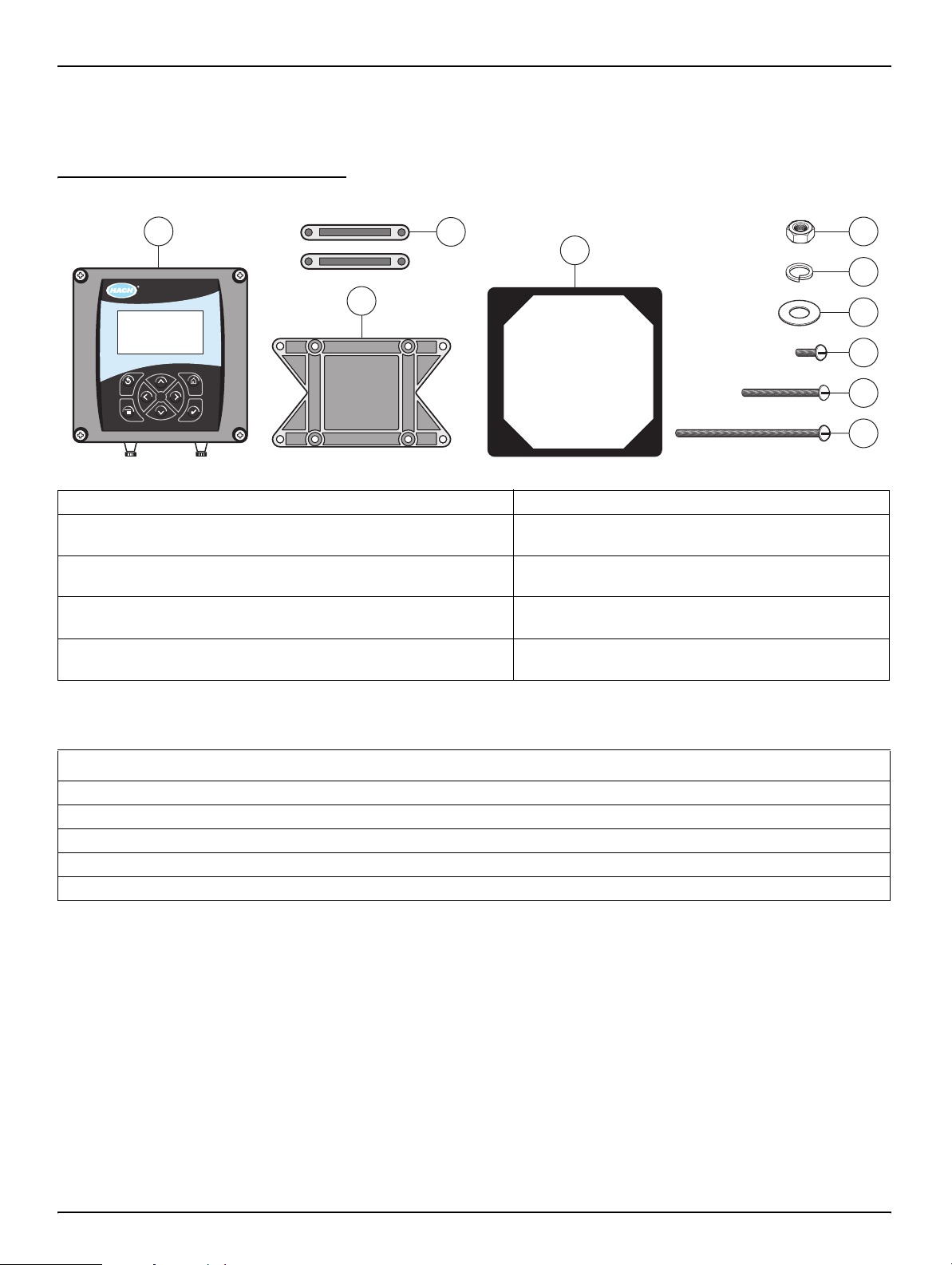
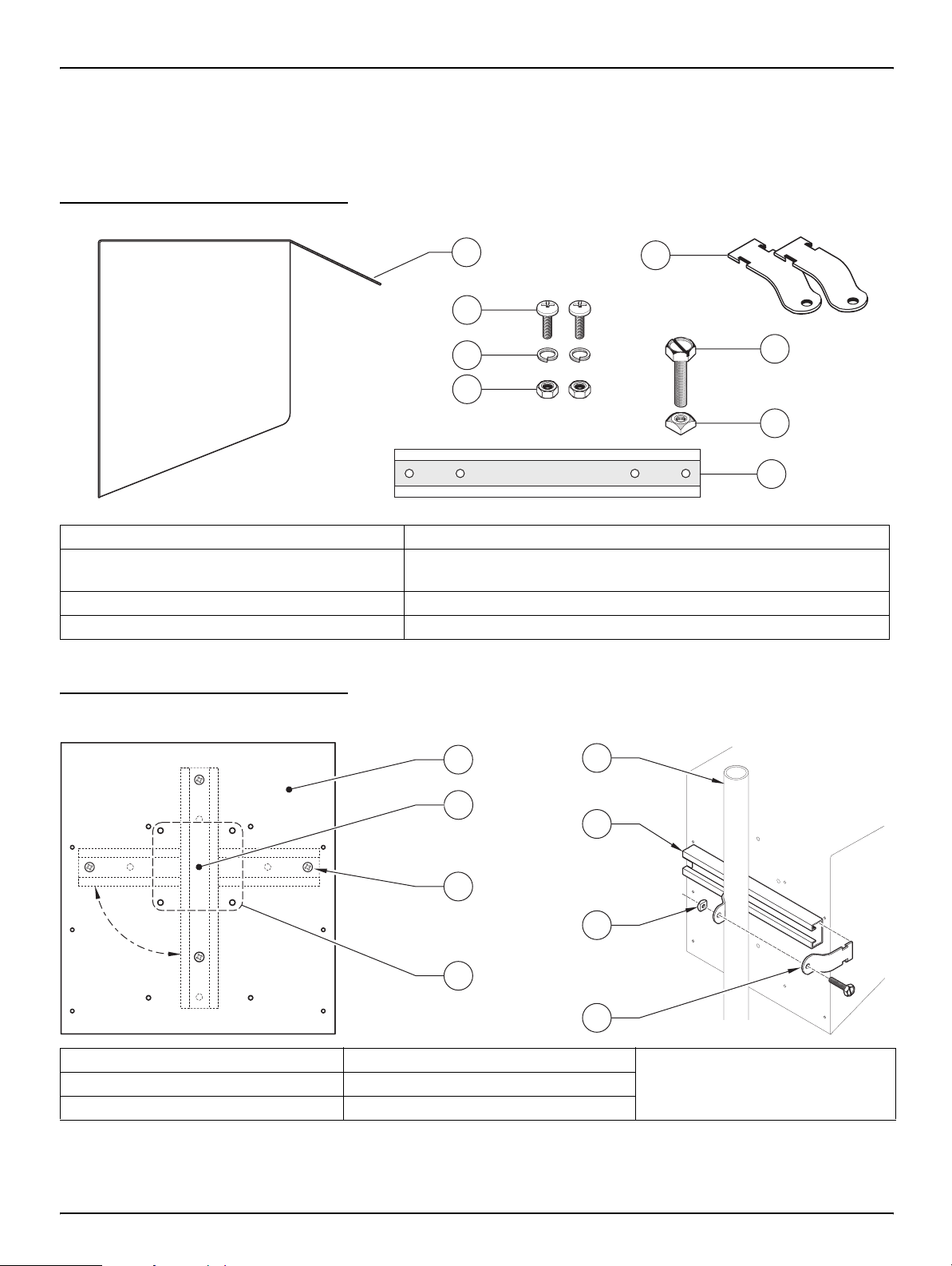
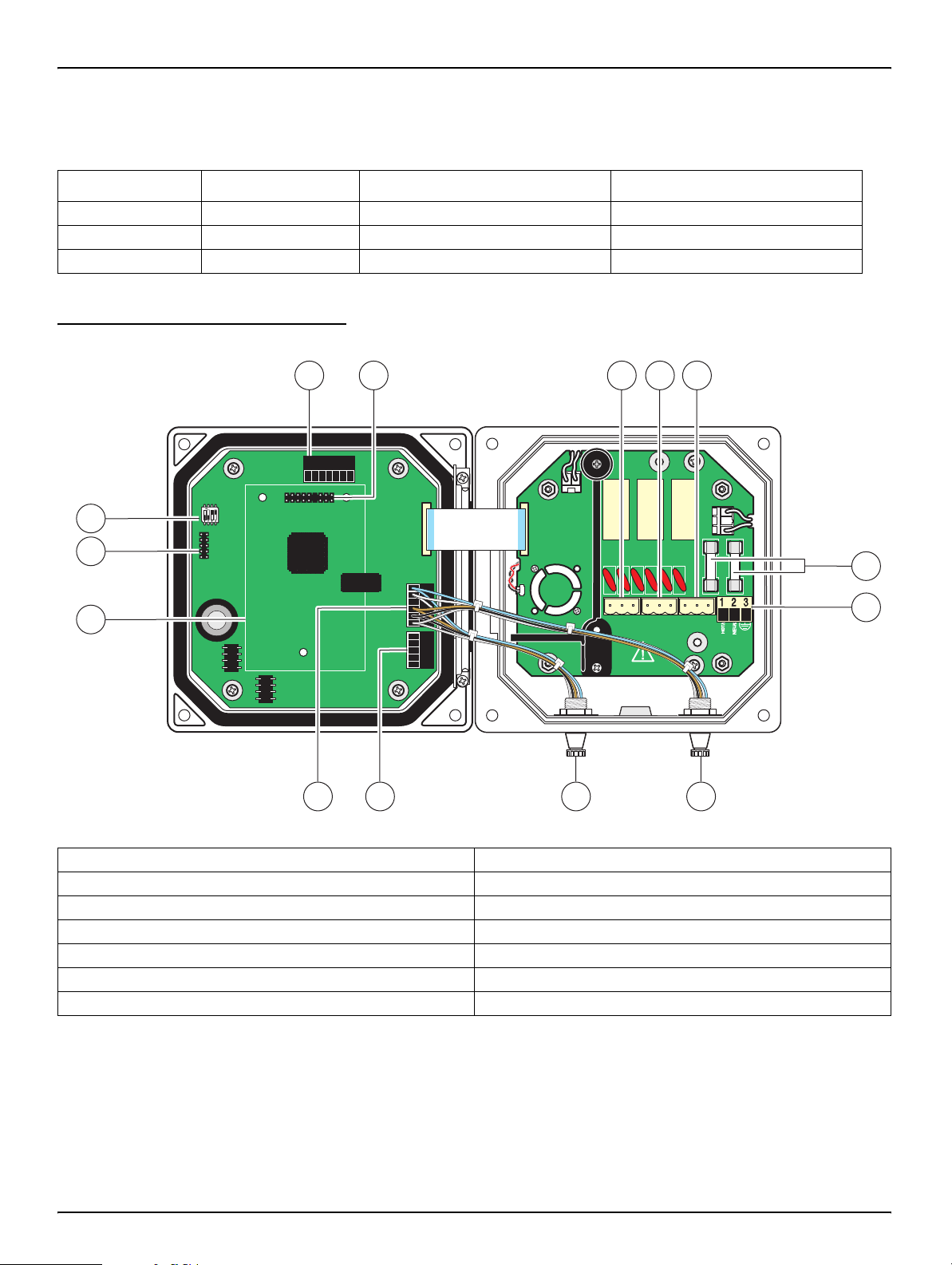
Figure 3-1 Components of a Basic System
1
sc100
1. Controller 6. Lock washer, ¼-inch I.D. (4), Cat. No . 8H1336
2. Mounting foot for panel mounting (2),
Cat. No. 1000B4F3222
3. Bracket f or panel and pipe mounting,
Cat. No. 1000C4F3217-101
4. Gasket for panel mounting, rubber,
Cat. No. 1000A4F3249-101
5. Hex nut, M6 (4), Cat. No. 5867300 10. Pan head screws (4), M6 x 1.0 x 150 mm,
3
2
4
7. Flat washer, ¼-inch I.D . (4),
Cat. No. 8H1346
8. Pan head screws (4), M6 x 1.0 x 20 mm,
Cat. No. 5867400
9. Pan head screws (4), M6 x 1.0 x 100 mm,
Cat. No. 5867500
No. 5867600
Cat.
5
6
7
8
9
10
Table 3-1 Customer Supplied Items
Item
14-AWG wire for electrical power connections in conduit or 115 or 230 V ac power cord plus a NEMA 4X-rated strain relief
High-quality, shielded instrumentation cable for connecting the analog outputs plus a NEMA 4X-rated strain relief.
Mounting hardware for the sensor (available from the manufacturer, order separately). See the sensor manual.
Sun shield for mounting configurations where the sun strikes the front of the display. See Figure 3-7 on page 8.
Common hand tools
5
Page 6
Installation
3.1 Mechanical Installation
Install in an environment that is protected from corrosive fluids.
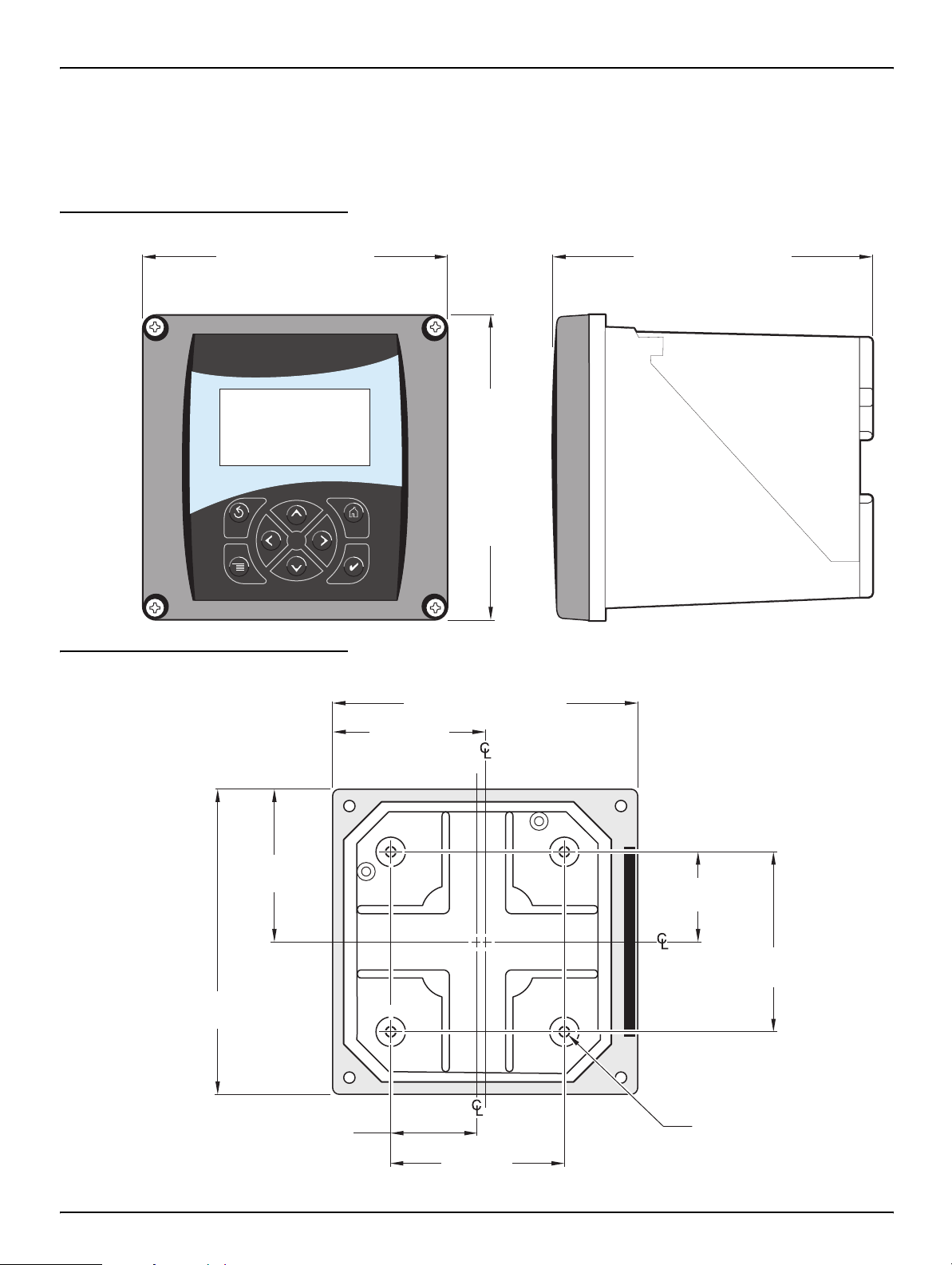
3.1.1 Controller Dimension Illustrations
Figure 3-2 Controller Dimensions
144.0 mm (5.67 inches) 150.0 mm (5.91 inches)
sc100
Figure 3-3 Controller Mounting Dimensions
144.02 mm (5.67 inches)
72.01 mm
(2.84 inches)
72.01 mm
(2.84 inches)
144.02 mm
(5.67 inches)
144.0 mm (5.67 inches)
40.14 mm
(1.58 inches)
80.27 mm
(3.16 inches)
40.14 mm (1.58 inches)
80.27 mm
(3.16 inches)
M6 x 1.0
6
Page 7
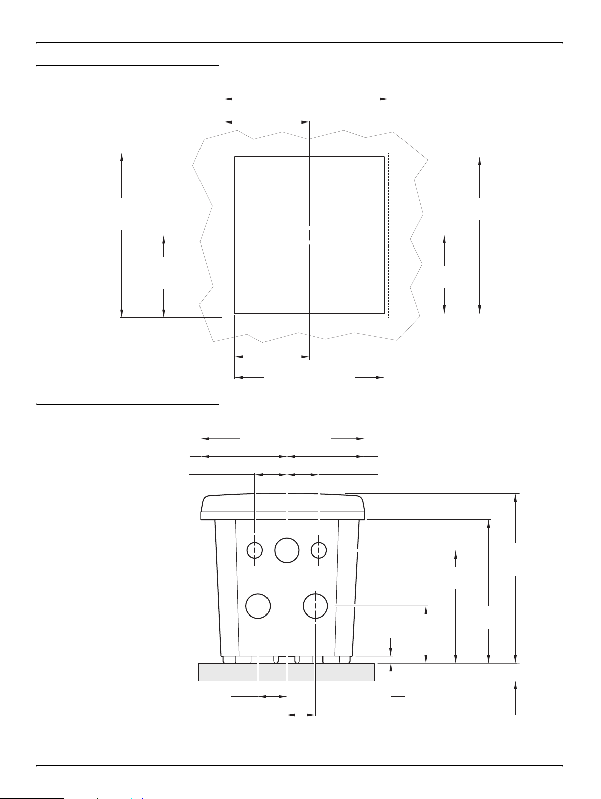
Figure 3-4 Panel Mount Cut-out Dimensions
75 mm (2.955 inches)
(ref only)
Installation
144 mm (5.67 inches)
(ref only)
144 mm
(5.67 inches)
(ref only)
72 mm
(2.835 inches)
(ref only)
66.67 mm (2.625 inches)
Figure 3-5 Conduit Hole Dimensions
75.07 mm (2.955 inches)
28.57 mm (1.125 inches)
135 mm
(5.31 inches)
67.4 mm
(2.65 inches)
133 mm (5.25 inches)
144 mm (5.67 inches)
68.96 mm (2.715 inches)
28.57 mm (1.125 inches)
25.4 mm (1.00 inch)
25.4 mm (1.00 inch)
99.31 mm
(3.91 inches)
50.8 mm
(2.00 inches)
6.35 mm (0.25 inch)
15.24 mm (0.60 inch)
(5.00 inches)
150 mm
(5.91 inches)
(ref only)
127 mm
7
Page 8
Installation
3.1.2 Using the Optional Sun Shield
The optional sun shield was designed to increase the readability of the display
by
screening it from direct sunlight. See Replacement Parts on page 21 for
ordering information.
Figure 3-6 Sun Shield Kit Components
1
2
3
4
1. Sun shield 5. Pipe mounting brackets (2), includes items 6 and 7, Cat. No. 9H1079
2. Pan head screws, M6 x 1.0 x 12 mm (6),
Cat. No. 200-1025
3. Lock washers, ¼-inch I.D. (2), Cat. No. 8H1336 7. Square nut, 5/16-inch (supplied with item number 5)
4. Hex nuts, M6 x 1.0 (2), Cat. No. 5867300 8. Uni-strut, 27 cm (10.5 inch) length, Cat. No. 276F1227
6. Hex/slotted head screw, 5/16-inch x 1.0-inch
(supplied with item number 5)
5
6
7
8
Figure 3-7 Mounting the Controller in the Sun Shield
1
2
3
4
1. Sun shield 4. Hole pattern for mounting controller 7. Pipe mounting bracket–slide into
2. Uni-strut (rotate 90° as required) 5. Pipe (vertical or horizontal as required)
3. Pan head screw, lock washer (2 each) 6. Hex/slotted head screw and square nut
5
2
6
7
uni-strut as shown. Secure the
fasteners to complete installation.
8
Page 9
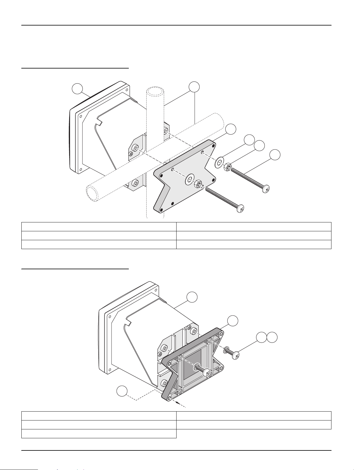
3.1.3 Mounting the Controller
Attach the controller to a rail or wall or mount it in a panel. Supplied mounting
hardware
Figure 3-8 Vertical or Horizontal Pipe Mounting the Controller
is shown in Figure 3-8, Figure 3-9, and Figure 3-10.
Installation
1
1. Controller 4. Flat washer, ¼-inch I.D. (4), Cat. No. 8H1346
2. Pipe (vertical or horizontal) 5. Hex nut, M6 (4), Cat. No. 5867300
3. Bracket, pipe mounting, Cat. No. 1000C4F3217-101 6. Pan head screw, M6 x 1.0 x 100 mm (4), Cat. No. 5867400
2
3
4
5
6
Figure 3-9 Wall Mounting the Controller
1
2
3
4
5
1. Controller 4. Pan head screw, M6 x 1.0 x 20 mm (4), Cat. No. 5867400
2. Bracket, Cat. No. 1000C4F3217-101 5. Customer-supplied hardware for wall mounting
3. Lock washer, ¼-inch I.D., Cat. No. 8H1336
9
Page 10
Installation
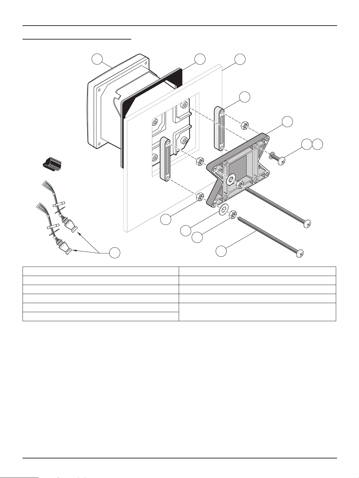
Figure 3-10 Panel Mounting the Controller
1
8
2
9
8
3
4
5
6
7
11
1. Controller 7. Lock washer, ¼-inch I.D., (4) Cat. No. 8H1336
2. Gasket, rubber, panel mount, Cat. No. 1000A4F3249-101 8. Hex nut (4), Cat. No. 5867300
3. Panel (maximum thickness is 9.5 mm (3/8 inch)) 9. Flat washer (4), Cat. No. 8H1346
4. Mounting Foot (2), Cat. No. 1000B4F3222 10. Pan head screw, M6 x 1.0 x 150 mm (4), Cat. No. 5867600
5. Mounting bracket, controller, Cat. No. 1000C4F3217-101 11. It may be necessary to remove the sensor connectors.
6. Pan head screw (4), Cat. No. 5867400
see procedure below.
10
To remove the sensor connectors bef ore inserting the controller enclosure into the
panel cut-out:
1. Disconnect the wires at terminal block J5, see Figure 3-20 on page 18.
2. Loosen and remove the nut securing the sensor connector inside the
enclosure. Remove the sensor connector and wires. Repeat step 1 and 2 for
the other sensor connector.
3. After the controller is in place in the panel, reinstall the senso r connectors and
reconnect the wiring to terminal J5 as shown in
Figure 3-20 on page 18.
10
Page 11

3.2 Electrical Installation
+
DATA
+
OUT 2
+
V
+
OUT 1
PCB
CONNECTOR
FIELD WIRING
INSULATION MUST
BE RATED TO
80° C MINIMUM
1
1
+
DATA+DATA
+
OUT 2+OUT 2
– DATA
– OUT 2
SERVICE REQUEST
SHIELD/CHASSIS GND
+V+
V
+
OUT 1+OUT 1
GND
– OUT 1
2
2
3
3
4
4
5
5
6
PROBES
ANALOG OUTPUTS
PCB
CONNECTOR
PCB
CONNECTOR
FIELD WIRING
INSULATION MUST
BE RATED TO
80° C MINIMUM
FIELD WIRING
INSULATION MUST
BE RATED TO
80° C MINIMUM
J1
J2
J4
NETWORK
INTERFACE
CARD
J3
J5
J6
U5
U9
S1
Installation
DANGER
The instrument must be installed
by qualified technical per s onn el
for adherence to all applicable
electrical codes.
High-voltage wiring for the controller is conducted behind the high voltage barrier
in the controller enclosure. The barrier must remain in place unless a qualified
installation technician is installing wiring for power, alarms, or relays. See
3-11 for barrier removal information.
3.2.1 Installation in Conduit
In hard-wired electrical applications, the power and safety ground service drops
for the instrument must be 18 to 12 AWG. See
relief and conduit opening sealing plug information. See section 3.2.3 on page 12
for wiring information.
3.2.2 Installation Using a Power Cord
A sealing-type strain relief to maintain the NEMA 4X/IP66 environmental rating
and a power cord less than 3
conductors (including a safety ground wire) can be used, see
on page 21. See Figure 3-12 on page 12 for strain relief and conduit opening
sealing plug assembly. See section 3.2.3 on page 12 for wiring information.
Figure 3-11 Removing Voltage Barrier
J1
S1
J2
U5
J4
U9
NETWORK
INTERFACE
CARD
J3
J5
J6
Figure
Figure 3-12 on page 12 for strain
meters (10 feet) in length with three 18-gauge
Replacement Parts
1
1
+
DATA
– DATA
2
SERVICE REQUEST
3
4
+
V
5
GND
6
1
+
OUT 2
– OUT 2
2
SHIELD/CHASSIS GND
3
4
+
OUT 1
5
– OUT 1
FIELD WIRING
INSULATION MUST
BE RATED TO
80° C MINIMUM
2
PCB
CONNECTOR
PROBES
ANALOG OUTPUTS
1. High voltage barrier 2. Unsna p the barrier latch then pull out to remove the barrier.
11
Page 12
Installation
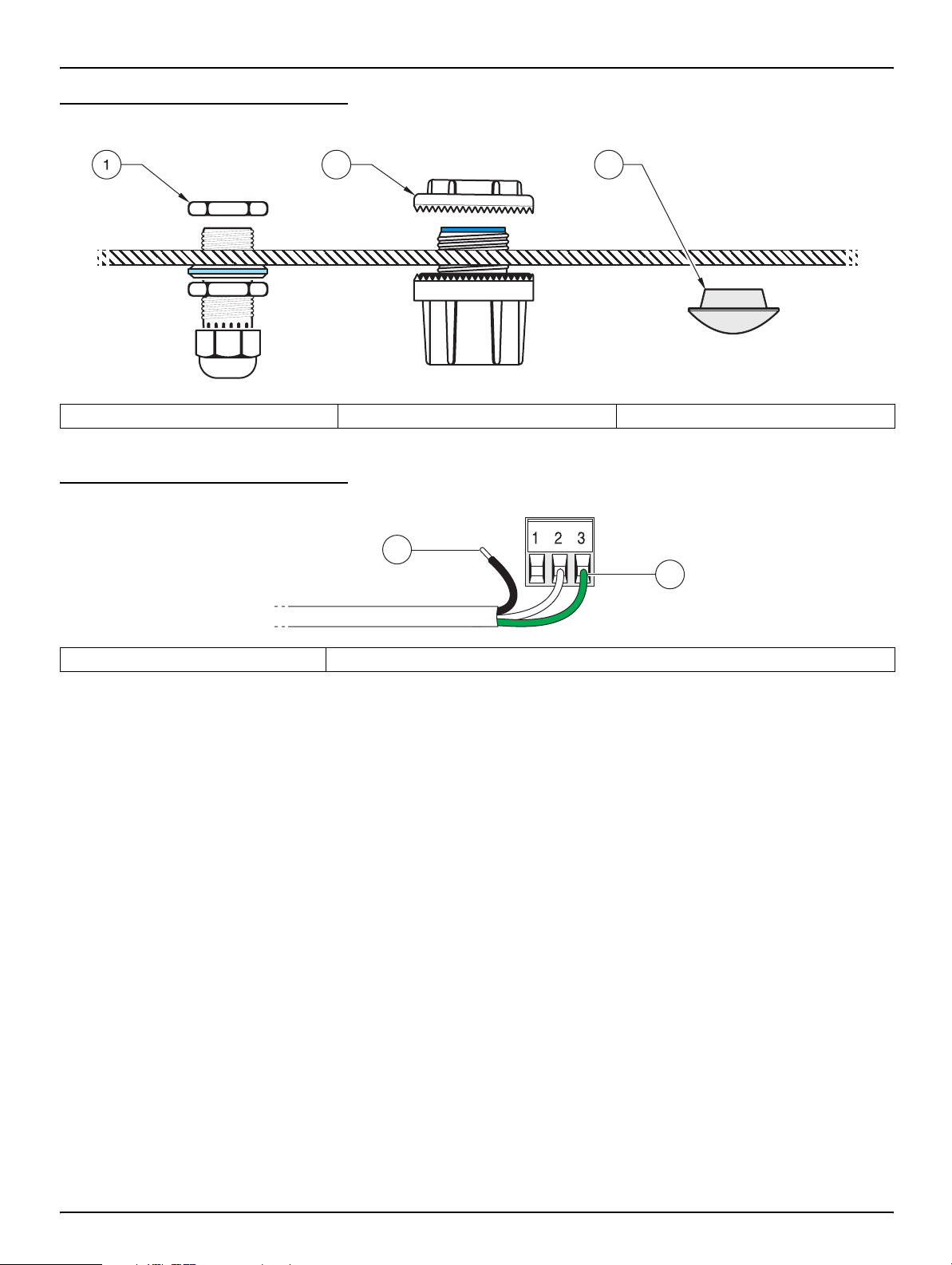
Figure 3-12 Using the Optional Stra in Reli ef and Conduit Plug
2
1. Power cord strain relief 2. Conduit strain relief 3. Conduit opening sealing plug
3
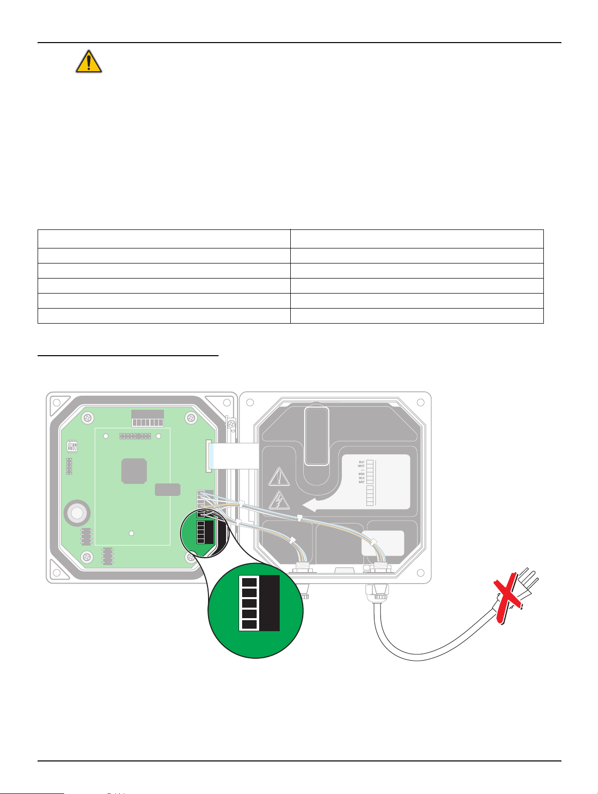
Figure 3-13 Proper Wire Preparation and Insertion
1
2
1. Strip ¼-inch of insulation. 2. Seat insulation against connector with no bare wire exposed.
3.2.3 Wiring for Power at the Controller
The instrument can be wired for line power by hard-wiring in conduit or by wiring
to a power cord. Regardless of the type of wire used, t he connections are m ade at
the same terminal. A local disconnect designed to meet local electrical code is
required and must be identified for all types of installation. See
Figure 3-16 on page 14 for suggest ed local disconnect configurations.
1. Obtain appropriate fittings with NEMA 4X/IP66 environmental rating.
2. Loosen the screws using a phillips-head screwdriver and open the hinged
controller cover.
3. Remove the high-voltage barrier (see Figure 3-11 on page 11).
4. Insert the wires through the strain relief fitting or conduit hub located in the
right-rear access hole in the bottom of the enclosure. Tighten the strain relief if
used, to secure the cord.
5. Properly prepare each wire (Figure 3-13) and insert each wire into the
terminal according to Table 3-2. Tug gently after each insertion to ensure the
connection is secure.
Figure 3-15 and
12
6. Seal any unused openings in the controller box with conduit opening sealing
plugs, see
Replacement Parts on page 21.
Page 13
Installation
RELAYB
7. Reinstall the high-voltage barrier and latch to secure.
Table 3-2 Power Wiring Information
Terminal Number Terminal Description Wire Color Code for North America Wire Color Code for Europe
1 Hot (L1) Black Brown
2 Neutral (N) White Blue
3 Protective Earth (PE) Green Green w/yellow tracer
Figure 3-14 Wiring Connections
312
45
J1
J3
14
S1
J2
CARD
U5
U9
11 10
F1
J5
RELAYA
J6
NONO
F2
NCNCNC
NO
COMCOMCOM
RELAYCRELAYB
89
13
12
J4
NETWORK
INTERFACE
1. J1—Network connector 8. Sensor connector
2. J2—Header for optional network interface card 9. Sensor connector
3. J5—Relay A connector 10. J6—Analog output (4–20 mA) connector
4. J6—Relay B connector 11. J5—Sensor connector for hard-wiring
5. J7—Relay C connector 12. Position for network interface card
6. Fuses (F1, F2) 13. Service port
7. J8—ac Power connections 14. Sensor terminator selector/service port configuration
6
7
13
Page 14

Installation
Figure 3-15 Local Disconnect for Power Cord
J1
S1
J2
J3
1
CARD
U5
U9
J5
J6
F1
NCNCNC
NONO
NO
COMCOMCOM
RELAYCRELAYBRELAYA
J4
NETWORK
INTERFACE
1. Power terminal 2. Power cord strain relief
Figure 3-16 Local Disconnect for Hard-wired Line Power
F2
2
J1
S1
J4
NETWORK
INTERFACE
J2
U5
U9
CARD
J3
J5
J6
F1
NCNCNC
NONO
NO
COMCOMCOM
RELAYCRELAYBRELAYA
1. Power terminal 2. Conduit strain relief
1
F2
2
14
Page 15

3.3 Alarms and Relays
NCNCNC
COMCOMCOM
NO
F1
F2
NONO
RELAYCRELAYBRELAYA
J1
J2
J4
S1
NETWORK
INTERFACE
CARD
J3
J5
J6
U5
U9
J5J5
The controller is equipped with three unpowered relays rated 100–230 V ac,
50/60
setup
3.3.1 Connecting the Relays
The relay connector accepts 18–12 AWG wire (as determined by load
application). Wire gauge less than 18 AWG is not recommended.
Installation
Hz, 5 amp resistive maximum. See the sensor manual for relay
details.
Danger: Relay loads must be
resistive. User must externally
limit current to the relays to
Amps by use of a fuse or
5
breaker.
Danger: ac power terminals are
designed for single wires. Do not
use more than one wire in each
terminal.
The controller contains three relays designed for use with high voltag e (greater
than 30V-RMS and 42.2V-PEAK or 60
information. The wiring is not designed for low voltage connections. Relay must
not be powered from t he same wiring used to powe r the cont roller . See the sensor
manual for relay setup
The Normally Open (NO) and Common (COM) relay contacts will be connected
when an alarm or other condition is active. The Normally Closed (NC) and
Common relay contacts will be connected when an alarm or other condition
is
inactive or when power is removed from the controller.
Figure 3-17 Alarm and Relay Connections
J1
S1
J4
NETWORK
INTERFACE
J2
U5
U9
CARD
J3
J5J5
J5
details.
3
2
1
V dc). Refer to Figure 3-17 for connection
J5 J6 J7
RELAY A RELAY B RELAY C
F1
F2
NCNCNC
NONO
NO
COMCOMCOM
RELAYCRELAYBRELAYA
J6
Disconnect
Power
15
Page 16
Installation
+
DATA
+
OUT 2
+
V
+
OUT 1
PCB
CONNECTOR
FIELD WIRING
INSULATION MUST
BE RATED TO
80° C MINIMUM
NCNCNC
COMCOMCOM
NO
F1
F2
NONO
RELAYCRELAYBRELAYA
J1
J2
J4
S1
NETWORK
INTERFACE
CARD
J3
J5
J6
U5
U9
1
1
+
DATA+DATA
+
OUT 2+OUT 2
– DATA
– OUT 2
SERVICE REQUEST
SHIELD/CHASSIS GND
+V+
V
+
OUT 1+OUT 1
GND
– OUT 1
2
2
3
3
4
4
5
5
6
PROBES
ANALOG OUTPUTS
PCB
CONNECTOR
PCB
CONNECTOR
FIELD WIRING
INSULATION MUST
BE RATED TO
80° C MINIMUM
FIELD WIRING
INSULATION MUST
BE RATED TO
80° C MINIMUM
J5J5
3.3.2 Connecting the Analog Outputs
Two isolated analog outputs (1 and 2) are provided, see Figure 3-18. Each out put
can be set to 0–20 or 4–20 mA, and can be assigned to represent the measured
parameter or secondary measurement such as temperature. Make connections
with twisted-pair shielded wire and connect the shield at the controlled component
end or at the control loop end. Do not connect the shield at both ends o f the cab le.
Use of non-shielded cable may result in radio frequency emission or susceptibility
levels higher tha n allowed. Maximum loop resistance is 500 ohm. Refer to the
sensor manual for output software setup.
Make wiring connections at the analyzer end as shown in Figure 3-18.
Table 3-3 Output Connections at Terminal Block J6
Recorder Wires Circuit Board Position
Output 2 + 1
Output 2 – 2
Shield 3
Output 1 + 4
Output 1 – 5
Figure 3-18 Analog Output Connections
J1
S1
J4
NETWORK
INTERFACE
CARD
J2
U5
J5J5
U9
J5
J6
J3
1
+
DATA
– DATA
2
SERVICE REQUEST
3
4
+
5
6
1
2
3
4
5
NCNCNC
NONO
COMCOMCOM
RELAYCRELAYBRELAYA
FIELD WIRING
INSULATION MUST
BE RATED TO
80° C MINIMUM
V
GND
F1
+
OUT 2
– OUT 2
SHIELD/CHASSIS GND
+
OUT 1
– OUT 1
NO
F2
PCB
CONNECTOR
PROBES
ANALOG OUTPUTS
1
2
3
4
5
J6
16
Page 17
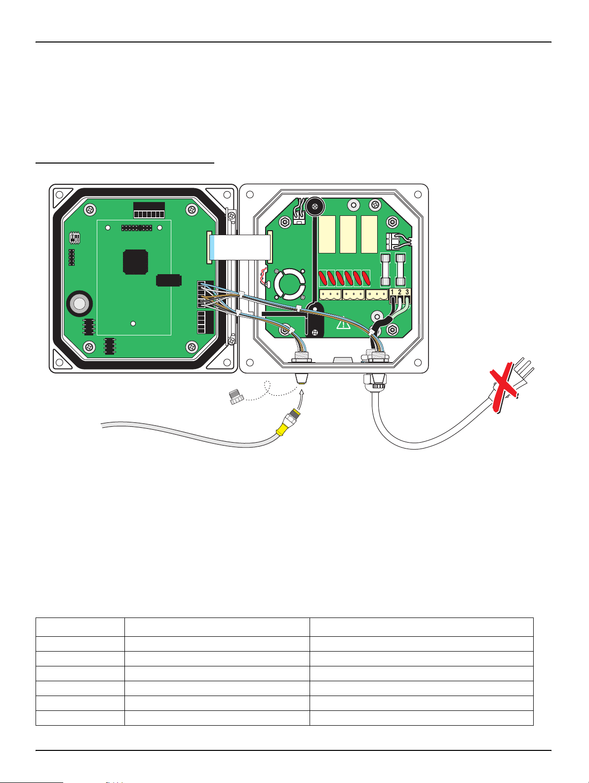
3.4 Connecting/Wiring the Sensor Cable
The sensor cable is supplied with a k eyed quick-connect fitting for easy
attachment to
connector opening in case the sensor must be removed. Optional extension
cables may be purchased to extend the sensor cable length. If the total cable
length exceeds 100 M (300 ft), a termination bo x must be installed. See the
Replacement Parts section in the sensor manual for part number information.
Figure 3-19 Attaching the Sensor using the Quick-connect Fitting
J1
S1
J2
J3
the controller, see Figure 3-19. Retain the connecto r cap to seal the
Installation
J4
From Probe
NETWORK
INTERFACE
CARD
U5
J5J5
J5J5
U9
J5
J6
F1
F2
NCNCNC
NONO
NO
COMCOMCOM
RELAYCRELAYBRELAYA
Modify the controller for sensor hard-wiring as follows:
1. Open the controller cover.
2. Disconnect and remove the existing wires between the quick connect and
terminal block J5, see
Figure 3-20 on page 18.
3. Remove the quick connect fitting and wires and install the threaded plug on
the opening to maintain the environmental rating.
Table 3-4 Wiring the Sensor at Terminal Block J5
Terminal Number Terminal Designation Wire Color
1 Data (+) Blue
2 Data (–) White
3 Service Request No Connection
4 +12 V dc Brown
5 Circuit Common Black
6 Shield Shield (grey wire in existing quick disconnect fitting)
17
Page 18

Installation
RELAY2
+
DATA
+
OUT 2
+
V
+
OUT 1
PCB
CONNECTOR
FIELD WIRING
INSULATION MUST
BE RATED TO
80° C MINIMUM
NCNCNC
COMCOMCOM
NO
F1
F2
NONO
RELAY3RELAY 2RELAY2RELAY 1
1
1
+
DATA+DATA
+
OUT 2+OUT 2
– DATA
– OUT 2
SERVICE REQUEST
SHIELD/CHASSIS GND
+V+
V
+
OUT 1+OUT 1
GND
– OUT 1
2
2
3
3
4
4
5
5
6
PROBES
ANALOG OUTPUTS
PCB
CONNECTOR
PCB
CONNECTOR
FIELD WIRING
INSULATION MUST
BE RATED TO
80° C MINIMUM
FIELD WIRING
INSULATION MUST
BE RATED TO
80° C MINIMUM
J1
J2
J4
NETWORK
INTERFACE
CARD
J3
J6
U5
U9
S1
J5
Figure 3-20 Hard-wiring the sensor
J1
S1
J4
NETWORK
INTERFACE
CARD
J2
U5
J5J5
J5
U9
J5
J6
J3
1
+
DATA
– DATA
2
SERVICE REQUEST
3
4
+
5
GND
6
1
+
2
3
4
+
5
– OUT 1
NCNCNC
NONO
COMCOMCOM
RELAY3RELAY 2
FIELD WIRING
INSULATION MUST
BE RATED TO
80° C MINIMUM
V
F1
OUT 2
– OUT 2
SHIELD/CHASSIS GND
OUT 1
NO
F2
PCB
CONNECTOR
PROBES
ANALOG OUTPUTS
RELAY1
Disconnect
Power
From Probe
1. Cut the connector from the sensor cable.
2. Reinstall the plug on the sensor access opening to maintain the
environmental rating.
3. Strip the insulation on the cable back 1-inch. Strip ¼-inch of each individ ual
wire end.
4. Wire as shown in Table 3-4.
5. Pass the cable through conduit and a conduit hub or a strain relief fitting and
an available access hole in the controller enclosure. Tighten the fitting.
6. Close and secure the cover.
3.5 Connecting the Optional Digital Output
At this time, the manufacturer supports ModBUS RS485, ModBUS RS232, and
ProfiBUS DP communication protocols . The optional digital output card is installed
in the location indicated in
user connection to the optional netw ork card. The terminal connection is based on
the selected network card. Ref er to the instructions supplied with t he network card
for more details.
Figure 3-21 on page 19. Terminal block J1 provides
18
Page 19

Table 3-5 Network Connections at Terminal Block J1
NCNCNC
COMCOMCOM
NO
F1
F2
NONO
RELAYCRELAYBRELAYA
J1
J2
J4
S1
NETWORK
INTERFACE
CARD
J3
J5
J6
U5
U9
J5J5J5J5
Installation
Terminal Number ModBUS RS485 2-wire ModBUS RS485 4-wire ModBUS RS232
1
1 D + RD + Rx A –
2 D – RD – — B1 +
3 — TD + Tx A2 –
4 — TD – — B2 +
5 Common Common Common Common
6 No connection No connection No connection No connection
7 Shield Shield Shield Shield
1. See Detail A.
Detail A RS232 Connections to Customer-supplied Computer 9-pin D Subminiature Connector
Common 5
Not used 4
Rx 3
Tx 2
Not used 1
9
8
7
6
ProfiBUS
Figure 3-21 Network Card Position in the Controller
1
J1
S1
J4
NETWORK
INTERFACE
2
CARD
J2
U5
U9
3
J3
J5J5J5J5
J5
J6
4
F1
F2
NCNCNC
NONO
NO
COMCOMCOM
RELAYCRELAYBRELAYA
1. J2—Network card header 2. Mounting hole (3) 3. Network card placement 4. J1 Terminal
19
Page 20
Section 4 Maintenance
RELAYB
4.1 Cleaning the Controller
With the enclosure securely closed, wipe the exterior with a damp cloth.
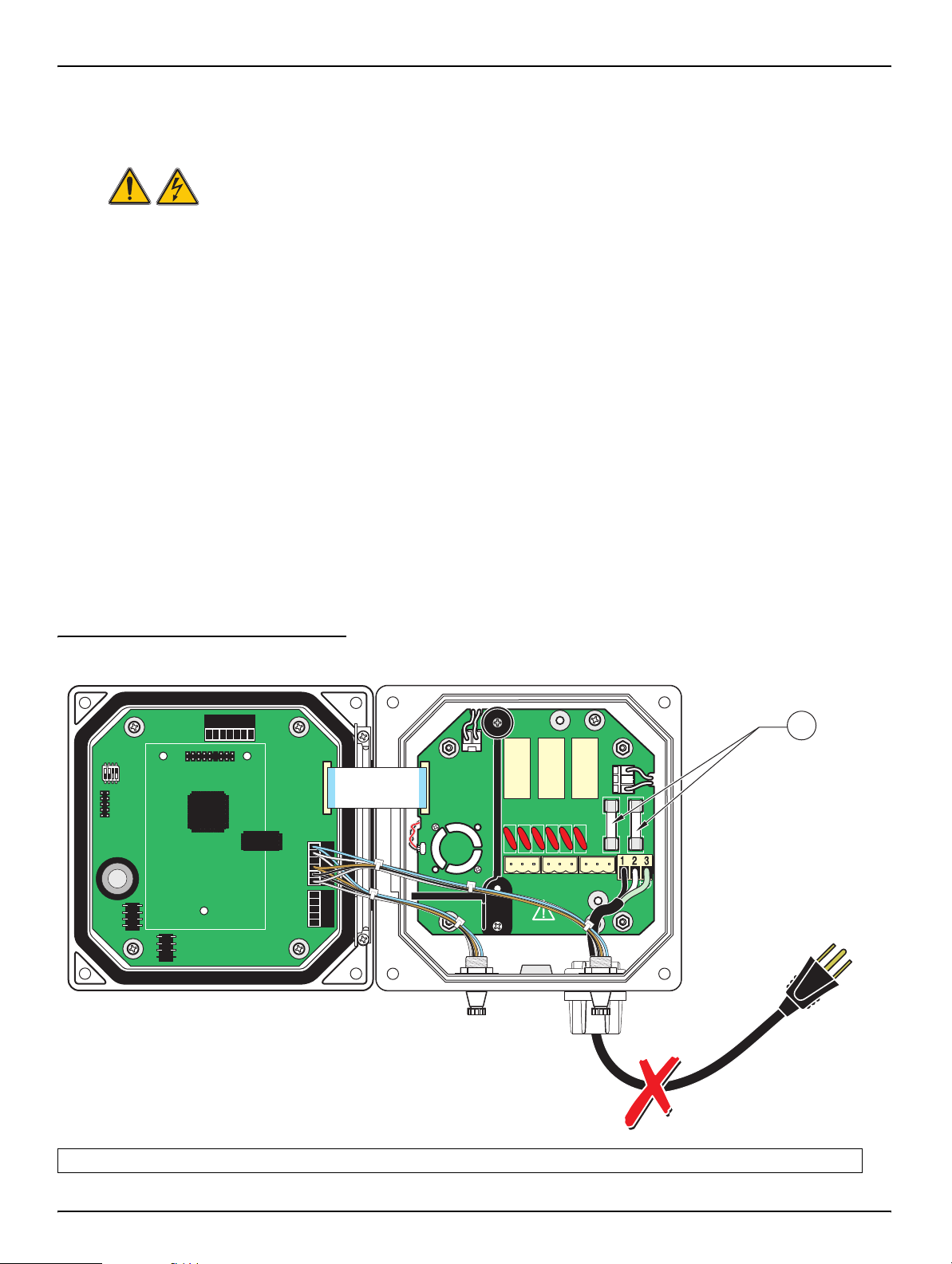
4.2 Fuse Replacement
The instrument contains two mains fuses. Failed fuses are an indication that an
equipment problem could exist. Problem resolution and fuse replacement should
be performed only by qualifie d service personnel. Refer to
following steps to replace the fuses:
1. Disconnect power to the controller (including power to relays if powered).
2. Open the hinged controller cover by completely loosening all four captive
screws in the cover.
3. Remove the high volta ge barrier; pull out on the lever of the captive fastener
then pull straight out on the barrier. Set the barrier aside for reinstallation.
4. Remove the fuses and install new fuses of th e same type and rating
(T,
1.6 A, 250 V, slow blow).
Figure 4-22 and the
Figure 4-22 Fuse Replacement
J1
S1
J4
NETWORK
INTERFACE
J2
U5
U9
CARD
5. Reinstall the high voltage barrier.
6. Close the controller cover and hand-tighten the four screws.
7. Reconnect power to the instrument.
J3
F1
J5
RELAYA
J6
NONO
F2
NCNCNC
NO
COMCOMCOM
RELAYCRELAYB
1
1. Fuses F1 and F2, T, 1.6 A, 250 V, slow blow
20
Disconnect
Power
Page 21

Section 5 Replacement Parts
Replacement Items
Item Cat. No.
Controller......................................................................................................................................................58600-00
Controller installation kit ...............................................................................................................................58672-00
Fuse, T, 1.6 A, 250 V, slow blow................................................................................................................... 52683-00
Instruction manual, English ..........................................................................................................................58600-18
Accessories
Sun shield.....................................................................................................................................................58690-00
Plug, conduit opening............................. ... .... ... ............................................................................................58687-00
Power cord with strain relief, 115 V ..............................................................................................................54488-00
Power cord with strain relief, 230 V .............................................................................................................54489-00
Strain relief, Heyco. ... ... .......................................... .... .......................................... .............................................16664
Digital output card for ModBUS RS232 communication...............................................................................59200-00
Digital output card for ModBUS RS485 communication...............................................................................59200-01
21
Page 22

Section 6 How to Order
U.S.A. Customers
By Telephone:
6:30 a.m. to 5:00 p .m. MST
Monday through Friday
(800) 227-HACH (800-227-4224)
By Fax:
(970) 669-2932
By Mail:
Hach Company
P.O. Box 389
Loveland, Colorado 80539-0389 U.S.A.
Ordering information by e-mail: orders@hach.com
Information Required
• Hach account number (if available) • billing address
• Your name and phone number • Shipping address
• Purchase order number • Catalog number
• Brief description or model number • Quantity
International Customers
Hach maintains a worldwide network of dealers and distributors. To locate the
representative neare st you, send an e-mail to: intl@hach.com or contact:
Hach Company World Headquarters; Loveland, Colorado, U.S.A.
Telephone: (970) 669-3050; Fax: (970) 669-2932
Technical and Customer Service (U.S.A. only)
Hach Technical and Customer Service Department personnel are eager to
answer questions about our products and their use. Specialists in analytical
methods, they are happy to put their talents to work for you.
Call 1-800-227-4224 or e-mail techhelp@hach.com
22
Page 23

Section 7 Repair Service
Authorization must be o btained from Ha ch Compan y before sending any items for
repair. Please contact the Hach Service Center serving your
In the United States:
Hach Company
Ames Service
100 Dayton Avenue
Ames, Iowa 50010
(800) 227-4224 (U.S.A. only)
FAX: (515) 232-3835
In Canada:
Hach Sales & Service Canada Ltd.
1313 Border Street, Unit 34
Winnipeg, Manitoba
R3H 0X4
(800) 665-7635 (Canada only)
Telephone: (204) 632-5598
FAX: (204) 694-5134
E-mail: canada@hach.com
location.
In Latin America, the Caribbean, the Far East, the
Indian Subcontinent, Africa, Europe, or the Middle East:
Hach Company World Headquarters,
P.O. Box 389
Loveland, Colorado, 80539-0389 U.S.A.
Telephone: (970) 669-3050
FAX: (970) 669-2932
E-mail: intl@hach.com
23
Page 24

Section 8 Limited Warranty
Hach Company warrants its products to the original purchaser against any defects that are due
to faulty material or workmanship for a period of *one year* from date of shipment unless
otherwise noted in the product manual.
The sc100 Controller is warranted for two years from the date of shipment.
In the event that a defect is disco vered during the warranty period, Hac h Company agrees that, at
its option, it will repair or replace the defective product or refund the purchase price, excluding
original shipping and handling charges. Any product repaired or replaced under this warranty
will be warranted only for the remainder of the original product warranty period.
This warranty does not apply to consumable products such as chemical reagents; or
consumable components of a product, such as, but not limited to, lamps and tubing.
Contact Hach Company or your distributor to initiate warranty support. Products may not be
returned without authorization from Hach Company.
Limitations
This warranty does not cover:
• Damage caused by acts of God, natural disaster, labor unrest, acts of war (declared or
undeclared), terrorism, civil strife or acts of any governmental jurisdiction
• Damage caused by misuse, neglect, accident or improper application or installation
• Damage caused by any repair or attempted repair not authorized by Hach Company
• Any product not used in accordance with the instructions furnished by Hach Company
• Freight charges to return merchandise to Hach Company
• Freight charges on expedited or express shipment of warranted parts or product
• Travel fees associated with on-site warranty repair
This warranty contains the sole express warranty made by Hach Company in connection with its
products. All implied warranties, including without limitation, the warranties of merchantability
and fitness for a particular purpose, are expressly disclaimed.
Some states within the United States do not allow the discla imer of implied warranti es and if this
is true in your state the above limitation may not apply to you. This warranty gives you specific
rights, and you may also have other rights that vary from state to state.
This warranty constitutes the final, complete, and exclusive statement of warranty terms and no
person is authorized to make any other warranties or representations on behalf of Hach
Company.
Limitation of Remedies
The remedies of repair, replacement or refund of purchase price as stated above are the
exclusive remedies for the breach of this warranty. On the basis of strict liability or under any
other legal theory, in no event shall Hach Company be liable for any incidental or consequential
damages of any kind for breach of warranty or negligence.
24
Page 25

Section 7 Compliance Information
Hach Co. certifies this instrument was tested thoroughly, inspected, and found to
meet its published specifications when it was shipped from the factory.
The Model SC-100 has been tested and is certified as indi cate d to the following
instrumentation standards:
Product Safety
UL 61010A-1 (ETL Listing # 65454)
CSA C22.2 No. 1010.1 (ETLc Certification # 65454)
Certified by Hach Co. to EN 61010-1 Amds. 1 & 2 (IEC1010-1) per
73/23/EEC, supporting test records by Intertek Testing Services.
Immunity
This equipment was tested for Industrial level EMC per:
EN 61326 (EMC Requirements for Electrical Equipment for Measurement,
Control and Laboratory Use)
records by Hach Company, certified compliance by Hach Company.
per 89/336/EEC EMC: Supporting test
Emissions
Standards include :
IEC 1000-4-2:1995 (EN 61000-4-2:1995) Electrostatic Discharge Immunity
(Criteria B)
IEC 1000-4-3:1995 (EN 61000-4-3:1996) Radiated RF Electromagnetic Field
Immunity (Criteria A)
IEC 1000-4-4:1995 (EN 61000-4-4:1995) Electrical Fast Transients/Burst
(Criteria B)
IEC 1000-4-5:1995 (EN 61000-4-5:1995) Surge (Criteria B)
IEC 1000-4-6:1996 (EN 61000-4-6:1996) Conducted Disturbances Induced
by RF Fields (Criteria A)
IEC 1000-4-11:1994 (EN 61000-4-11:1994) Voltage Dip/Short Interruptions
(Criteria B)
Additional Immunity Standard/s include:
ENV 50204:1996 Radiated Electromagnetic Field from Digital Telephones
(Criteria A)
This equipment was tested for Radio Frequency Emissions as follows:
Per 89/336/EEC EMC: EN 61326:1998 (Electrical Equipment for
measurement, control and laboratory use—EMC requirements) Class “A”
emission limits. Supporting test records by Hewlett Packard, Fort Collins,
Colorado Hardware Test Center (A2LA # 0905-01) and certified compliance
by Hach Company.
Standards include :
EN 61000-3-2 Harmonic Disturbances Caused by Electrical Equipment
EN 61000-3-3 V oltage Fluct uation (Flick er) Disturbances Caused b y Electrical
Equipment
25
Page 26

Compliance Information
Additional Emissions Standard/s include:
EN 55011 (CISPR 11), Class “A” emission limits
Canadian Interference-causing Equipment Regulation, IECS-003, Class A
Supporting test records by Hewlett Packard, F ort Collins, Colorado Hardware Test
Center (A2LA # 0905-01) and certified compliance by Hach Company.
This Class A digital apparatus meets all requirements of the Canadian
Interference-cau sing Equipment Regulations.
Cet appareil numèrique de la classe A respecte toutes les exigences du
Rëglement sur le matÈriel brouilleur du Canada.
FCC PART 15, Class “A” Limits
Supporting test records by Hewlett Packard, Fort Collins, Colorado Hardware Test
Center (A2LA # 0905-01) and certified compliance by Hach Company.
This device complies with Part 15 of the FCC Rules. Operation is subject to the
following two conditions:
(1) this device may not cause harmful interference, and (2) this device must
accept any interfer ence receiv ed, including interf er ence that ma y cause undesired
operation.
Changes or modifications to this unit not expressly approved by the party
responsible for compliance could void the user's authority to operate the
equipment.
This equipment has been tested and found to comply with the limits for a Class A
digital device, pursuant to Part 15 of the FCC Rules. These limits are designed to
provide reasonable pr otection against harmful interf erence when th e equipment is
operated in a commercial en vir on men t. This e qu ipme nt ge nerates, uses, and can
radiate radio frequency energy and, if not installed and used in accordance with
the instruction manual, may cause harmful interference to radio communications.
Operation of this equipment in a residential area is likely to cause harmful
interference, in which case the user will be required to correct the interference at
his own expense. The following techniques of re ducing the interference problems
are applied easily.
1. Disconnect the Model sc100 Controller from its power source to verify that it is
or is not the source of the interference.
2. If the Model sc100 Controller is connected into the same outlet as the device
with which it is interfering, try another outlet.
26
3. Move the Model sc100 Controller away from the device receiving the
interference.
4. Reposition the receiving antenna for the device receiving the interference.
5. Try combinations of the above.
Page 27

Index
A
Alarms ......................................................................... 15
Analog Outputs
............................................................16
C
Cleaning
Controller
Compliance Information
Components
Customer Supplied
Controller
Enclosure Description
.............................................................. 20
.............................................. 25
................................................. 5
.............................................4
D
Digital Output ...............................................................18
E
Electrical Installation .................................................... 11
Conduit
Connecting/Wiring the Sensor Cable
Hard-wiring the Sensor
Power Cord
..................................................................11
.................... 17
......................................... 17
........................................................... 11
F
Fuse
Rating
....................................................................20
Replacement
......................................................... 20
H
hard-wired electrical applications ................................11
I
Installation ..................................................................... 6
Controller
Panel
Panel Mounting
Pipe Mounting
Wall Mounting
................................................................ 9
....................................................................... 7
..................................................... 10
......................................................... 9
......................................................... 9
M
ModBUS RS232 .................................................... 18, 21
ModBUS RS485
.......................................................... 21
O
Output
Connections
Outputs
........................................................................ 16
.......................................................... 16
P
Parts ............................................................................ 21
R
Relays ......................................................................... 15
Connecting
Specifications
Repair Service
Replacement
............................................................ 15
.......................................................... 3
............................................................. 23
............................................................... 21
S
Specifications ................................................................ 3
Sun Shield
..................................................................... 8
W
Wire preparation .......................................................... 12
27
Page 28

Visit http: //www.hach.com
 Loading...