

Page 1

DOC023.53.90007
sc1000 controller
USER MANUAL
April 2008, Edition 1
© Hach Company, 2008. All rights reserved. Printed in the U.S.A. as/cw
Page 2

Page 3

Table of Contents
Section 1 Specifications.................................................................................................................... 5
Section 2 General Information......................................................................................................... 9
2.1 Safety information........................................................................................................................ 9
2.1.1 Use of hazard information................................................................................................... 9
2.1.2 Precautionary labels ......................................................................................................... 10
2.2 General product information ...................................................................................................... 10
2.3 Controller storage ...................................................................................................................... 10
Section 3 Installation........................................................................................................................ 11
3.1 Mechanical installation............................................................................................................... 11
3.1.1 Controller dimensions ....................................................................................................... 12
3.2 Mounting the controller .............................................................................................................. 13
3.2.1 Wall mounting ................................................................................................................... 13
3.2.2 Vertical or horizontal pipe mounting.................................................................................. 14
3.2.3 Panel Mounting ................................................................................................................. 14
3.2.4 Sun-shield.........................................................................................................................14
3.3 Wiring safety information ........................................................................................................... 14
3.3.1 Electrostatic discharge (ESD) considerations................................................................... 15
3.4 Electrical installation .................................................................................................................. 16
3.4.1 Installation in hard-wired applications ............................................................................... 16
3.4.2 Installation using a power cord ......................................................................................... 17
3.4.3 Wiring for AC power at the controller ................................................................................ 20
3.4.4 Wiring for 24 VDC power at the controller ........................................................................ 24
3.5 DIN rail expansion modules....................................................................................................... 26
3.6 Expansion cards ........................................................................................................................ 27
3.6.1 Relay card connections.....................................................................................................28
3.6.2 Input card connections...................................................................................................... 31
3.6.3 Output card connections................................................................................................... 33
3.6.4 Modbus card connections ................................................................................................. 34
3.6.5 Profibus DP card connections........................................................................................... 35
3.6.6 Remove/Replace an expansion card................................................................................ 37
3.7 Install an sc1000 network (sc1000 bus connection) .................................................................. 37
3.7.1 sc1000 network connections............................................................................................. 38
3.8 Connect probes to the sc1000 controller ................................................................................... 43
3.8.1 Connect the probe data cable........................................................................................... 43
3.8.2 Add probe connections ..................................................................................................... 44
3.8.3 Connect AC powered sc probes ....................................................................................... 44
3.9 Service port connection (LAN connection)................................................................................. 44
3.10 GSM modem connection ......................................................................................................... 45
3.10.1 Safety precautions .......................................................................................................... 45
3.10.2 SIM card requirements.................................................................................................... 46
3.10.3 Insert the SIM card into the display module.................................................................... 47
3.10.4 Connect the external GSM antenna to the display module............................................. 48
3.11 Storage card (SD card)............................................................................................................ 49
3.11.1 Insert the storage card into the display module .............................................................. 49
3.11.2 Prepare the storage card ................................................................................................ 50
Section 4 System Start Up.............................................................................................................. 51
Section 5 Standard Operations...................................................................................................... 53
5.1 The display module.................................................................................................................... 53
5.1.1 Attach the display module to the probe module................................................................ 53
5.1.2 Tips for the use of the touch screen.................................................................................. 54
5.1.3 The display modes............................................................................................................ 54
1
Page 4

Table of Contents
5.2 The measured value display ......................................................................................................55
5.2.1 Daily and weekly trend lines..............................................................................................56
5.2.2 Configure the measured value display ..............................................................................56
5.3 The Graph display ......................................................................................................................56
5.4 The Main menu display ..............................................................................................................58
5.5 The alphanumeric keypad ..........................................................................................................59
5.6 Calibrate the touch screen .........................................................................................................59
5.7 Specify the displayed language..................................................................................................59
5.8 Set the time and date .................................................................................................................60
5.9 Set up system security (passcode protection)............................................................................60
5.9.1 Set the passcode...............................................................................................................60
5.10 Add and remove favorites ........................................................................................................61
5.11 Add new components...............................................................................................................61
5.12 Configure the network modules (Profibus/Modbus cards) .......................................................62
5.12.1 Configure the Profibus/Modbus card...............................................................................62
5.12.2 Error and status register..................................................................................................64
5.12.3 Profibus/Modbus configuration example .........................................................................66
5.13 Remote control.........................................................................................................................67
5.13.1 Prepare the LAN connection ...........................................................................................67
5.13.2 Set up the LAN connection..............................................................................................67
5.13.3 Set up the dial-up connection..........................................................................................68
5.13.4 Access the sc1000 controller through a web browser.....................................................70
5.14 Log data ...................................................................................................................................71
5.14.1 Save log files to the storage card ....................................................................................71
5.14.2 Save log files through browser access............................................................................71
5.14.3 Remove log files through browser access.......................................................................72
5.15 Formula editor for output and relay card ..................................................................................73
5.15.1 Add a formula..................................................................................................................73
5.15.2 Add a formula with measurement values from other probes...........................................74
5.15.3 Formula operations..........................................................................................................74
Section 6 Advanced Operations ....................................................................................................77
6.1 Sensor status menu ...................................................................................................................77
6.2 Sensor setup menu ....................................................................................................................77
6.3 System setup menu....................................................................................................................78
6.3.1 Output setup menu............................................................................................................78
6.3.2 Current inputs menu..........................................................................................................83
6.3.3 Relay menu .......................................................................................................................87
6.3.3.1 General relay settings (available in all relay working modes)...................................87
6.3.3.2 Function set to ALARM working mode .....................................................................88
6.3.3.3 Function set to FEEDER CONTROL working mode ................................................90
6.3.3.4 Function set to 2 POINT CONTROL working mode.................................................93
6.3.3.5 Function set to WARNING working mode ................................................................97
6.3.3.6 Function set to PWM CONTROL/LINEAR working mode ........................................99
6.3.3.7 Function set to PWM CONTROL/PID CONTROL working mode...........................102
6.3.3.8 Function set to FREQ. Control / Linear working mode...........................................103
6.3.3.9 Function set to FREQ. Control/PID CONTROL mode............................................105
6.3.3.10 Function set to TIMER working mode ..................................................................106
6.3.3.11 Function set to SYSTEM ERROR working mode.................................................108
6.3.4 Network Modules (Profibus, Modbus) .............................................................................109
6.3.4.1 Profibus ..................................................................................................................109
6.3.4.2 Modbus...................................................................................................................111
6.3.5 GSM module....................................................................................................................113
6.3.6 Device management........................................................................................................115
2
Page 5

Table of Contents
6.3.7 Display settings............................................................................................................... 115
6.3.8 Browser access............................................................................................................... 116
6.3.9 Storage card ................................................................................................................... 116
6.3.10 Security setup ............................................................................................................... 117
6.4 Test/Maint Menu...................................................................................................................... 117
6.4.1 Bus status ....................................................................................................................... 118
Section 7 Maintenance .................................................................................................................. 119
7.1 General maintenance............................................................................................................... 119
7.2 Fuse replacement.................................................................................................................... 119
Section 8 Troubleshooting ........................................................................................................... 121
8.1 General problems and GSM module errors............................................................................. 121
8.2 GSM Module errors.................................................................................................................. 122
8.3 Error and warning messages...................................................................................................122
8.3.1 Message type.................................................................................................................. 122
8.3.2 Message format .............................................................................................................. 123
8.3.3 Error and warning ID numbers........................................................................................ 123
8.4 SMS service............................................................................................................................. 124
8.4.1 Configure SMS destination ............................................................................................. 124
8.4.2 SMS format..................................................................................................................... 124
8.5 Test the expansion cards in the Maintenance menu ............................................................... 126
8.5.1 Test the output card ........................................................................................................ 126
8.5.2 Test the input card .......................................................................................................... 127
8.5.3 Test the relay card .......................................................................................................... 128
Section 9 Replacement Parts and Accessories....................................................................... 129
9.1 Expansion cards ...................................................................................................................... 129
9.2 External DIN rail modules ........................................................................................................ 129
9.3 Internal network components................................................................................................... 129
9.4 Accessories.............................................................................................................................. 129
9.5 Replacement parts................................................................................................................... 130
9.6 Exploded view drawings .......................................................................................................... 132
Section 10 Contact Information................................................................................................... 137
Section 11 Certification ................................................................................................................. 139
Appendix A DIN Rail Expansion Modules................................................................................. 141
3
Page 6

Table of Contents
4
Page 7
Section 1 Specifications
Specifications are subject to change without notice.
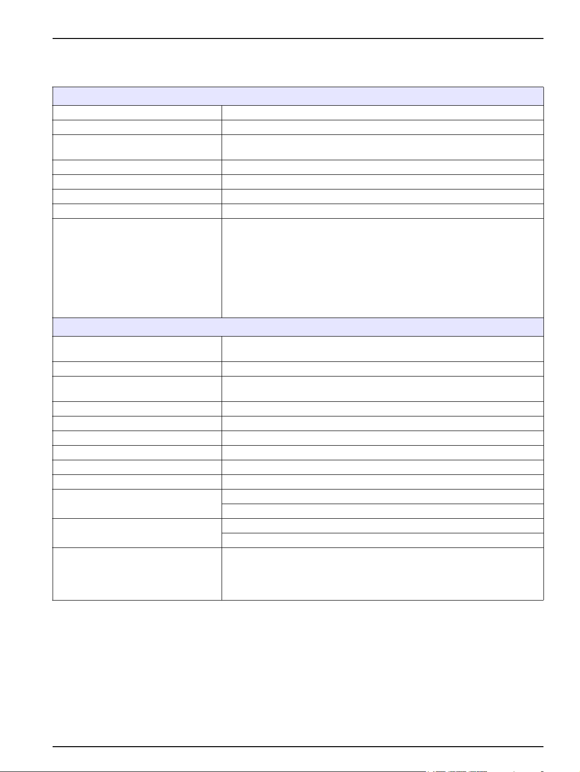
Display Module
Component description Display module for menu-based operation
Enclosure Plastic housing, enclosure rating IP65
Screen display
Operating temperature –20 to 55 °C (–4 to 131 °F); 95 % relative humidity, non-condensing
Storage temperature –20 to 70 °C (–4 to 158 °F); 95 % relative humidity, non-condensing
Weight Approximately 1.2 kg
Dimensions 200 × 230 × 50 mm (7.9 × 9 × 2 inches)
Optional expansions
Probe Module
QVGA, 320 x 240 pixels, viewing area: 111,4 mm x 83,5 mm, 256 colors, touch
screen
GSM modem
The sc1000 display module with integrated GSM/GPRS modem transmits data
SMS messages and GPRS services in GSM nets.
The sc1000 is offered with different GSM frequency bands:
MC55 EGSM900 GSM1800 GSM1900
MC56 GSM1800 GSM1900 GSM850
MC55/56 features GPRS multislot class 10 and supports the GPRS coding
schemes CS-1, CS-2, CS-3 and CS-4.
Component description
Enclosure Metal housing with corrosion-resistant surface finish, IP65 rating
Power requirements
Probe inputs (optional)
Measuring range Dependent on probe.
Operating temperature –20 to 55 °C (–4 to 131 °F); 95 % relative humidity, non-condensing
Storage temperature –20 to 70 °C (–4 to 158 °F); 95 % relative humidity, non-condensing
Weight Approximately 5 kg, depending on configuration
Optional expansions Analog Outputs, Analog/Digital Inputs, Relays, Digital fieldbusses
Dimensions
Fuse ratings
sc1000 network cable
1
Probe module for the connection of sc probes, optional expansions and power
supply
100–240 V ± 10 VAC, 50 / 60 Hz, max. 2000 VA, Category II or 24 VDC
(18–30 VDC), max. 75 W
4, 6, or 8 probes. All parameters can be configured and combined as required.
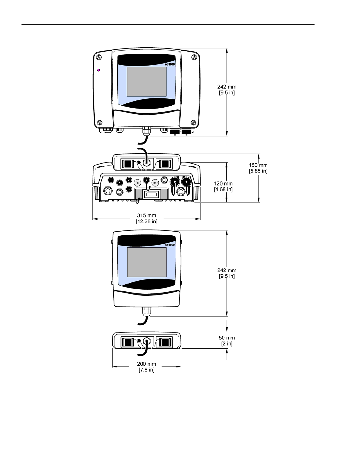
Without display module: 315 × 242 × 120 mm (12.4 × 10.1 × 4.8 inches)
With display module: 315 × 242 × 150 mm (12.4 × 10.1 × 6 inches)
100–240 VAC: F1, F2: M 3,5 A (medium slow-blow); F3, F4: T 8 A; 100–240 V
24 VDC: 1 fuse, T 6,3 A; 24 VDC
Double-shielded control cable with 2 cores, 24 AWG, stranded, CU wire
Characteristics impedance at 1 KHz > 100 W, wire color: red and green.
Outer sheath of the cable is UV and water resistant
External diameter of cable is 3.5–5 mm
5
Page 8

Specifications
Plug-in Expansion Cards
Component description Plug-in expansion cards for installation in the probe module
Operating temperature –20 to 55 °C (–4 to 131 °F); 95% relative humidity, non-condensing
Storage temperature –20 to 70 °C (–4 to 158 °F); 95% relative humidity, non-condensing
Analog output card
Analog/digital input card 4 x analog/digital inputs (0–20 mA or 4–20 mA) Terminals max. 1.5 mm
Internal relay card
Fieldbus interface card Modbus RS485 (YAB021), Modbus RS232 (YAB047) or Profibus DP (YAB020)
DIN Rail Switch Cabinet Expansion Modules
Function
Enclosure rating IP20
Power supply 24 VDC (max. 30 V) from base module
Operating temperature 4 to 40 °C (39 to 104 °F); 95% relative humidity, non-condensing
Storage temperature –20 to 70 °C (–4 to 158 °F); 95% relative humidity, non-condensing
Base module (LZX915)
Relay module (LZX920)
Output module (LZX919)
Input module (LZX921)
4 x analog current outputs (0–20 mA or 4–20 mA, max. 500 Ohm)
Terminals max. 1.5 mm2 (AWG15)
2
4 x change over contacts (SPDT)
Maximum switching voltage: 250 VAC, 125 VDC
Nominal Switching Current: 250 VAC, 5 A; 125 VAC, 5 A; 30 VDC, 5 A
Terminals max. 1.5 mm2 (AWG15)
For installation in the switch cabinet. Any expansions required can be combined
when a base module is available.
Supply of expansion modules with 24 VDC and connection to the sc1000
network
Setting terminating resistor (with DIP switch) for the sc1000 network
Provision of connection for a display module (LXV402) for the configuration of
the system
Base module can supply a maximum of 2000 mA to the extension modules.
Dimensions: 23 x 100 x 115 mm (1 x 4 x 4.5 in.)
4 x normally closed into change over contacts (SPDT)
Maximum switching voltage: 250 VAC, 125 VDC
Maximum switching current: 250 VAC, 5 A; 125 VAC, 5 A; 30 VDC, 5 A
Maximum switching power: 150 W
Can be programmed for limit, status-monitoring or for various control functions,
communication status indication by LED.
Terminals max. 2.5 mm2 (AWG 11)
Current consumption: <100 mA
Dimensions: 45 x 100 x 115 mm (2 x 4 x 4.5 in.)
2 analog current outputs (0–20 mA or 4–20 mA, max. 500 Ohm)
Terminals max. 2.5 mm2 (AWG 11)
Current consumption: <150 mA
Dimensions: 23 x 100 x 115 mm (1 x 4 x 4.5 in.)
Analog/Digital inputs (can be programmed as 0–20 mA or 4–20 mA), INPUT or
digital INPUT
Internal resistance: 180 Ohm
Terminals max. 2.5 mm2 (AWG 11)
Current consumption: <100 mA
Dimensions: 23 x 100 x 115 mm (1 x 4 x 4.5 in.)
6
Page 9
Specifications
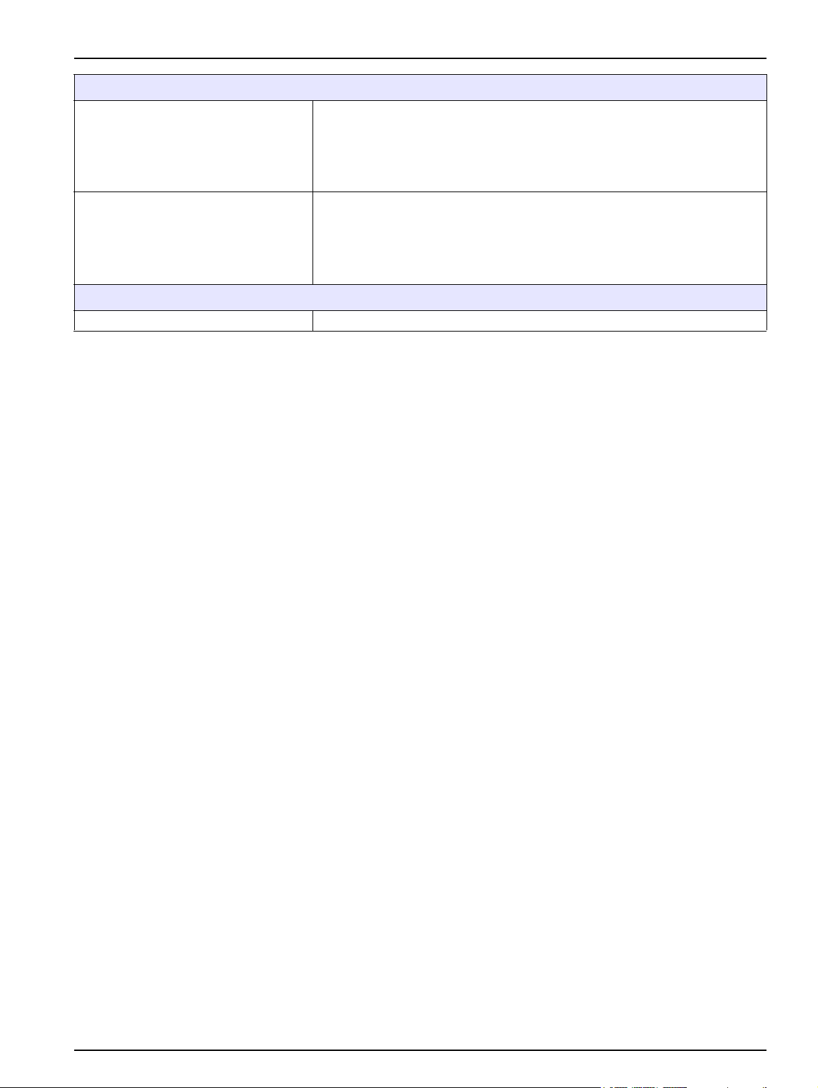
Certifications
sc1000 with system components
- cTUVus to UL 61010-1 & CAN/CSA 22.2 No. 61010-1
North America
Europe
Warranty
Warranty 1 year
1
When installing additional probes, observe the maximum total power of the system. Only two 1720E Turbidity instruments can
be used simultaneously on an sc1000 probe module.
Important Note: All modules and cards are developed according to DIN EN 61326 “Surge
protection”.
sc1000 with GSM Module
- FCC ID No. QIPMC56
- Industry Canada ID No. 267W-MC56
sc1000 with system components:
- CE Conforms to LV-Directive 2006/95/EC, EMC-Directive 2004/108/EC
- TUV-GS to EN61010-1
sc1000 with GSM Module:
- CETECOM ICT GmbH Registration No. M352023P-EO
7
Page 10

Specifications
8
Page 11
Section 2 General Information
The information in this manual has been carefully checked and is believed to be
accurate. However, the manufacturer assumes no responsibility for any inaccuracies that
may be contained in this manual. In no event will the manufacturer be liable for direct,
indirect, special, incidental or consequential damages resulting from any defect or
omission in this manual, even if advised of the possibility of such damages. In the interest
of continued product development, the manufacturer reserves the right to make
improvements in this manual and the products it describes at any time, without notice or
obligation.
Revised editions are found on the manufacturer’s web site.
2.1 Safety information
Please read this entire manual before unpacking, setting up or operating this equipment.
Pay attention to all danger, warning and caution statements. Failure to do so could result
in serious injury to the operator or damage to the equipment.
Make sure that the protection provided by this equipment is not impaired, do not use or
install this equipment in any manner other than that specified in this manual.
DANGER
The manufacturer products designed for outdoor use are provided with a high level
of ingress protection against liquids and dust. If these products are connected to a
mains electricity socket by means of a cable and plug rather than by fixed wiring,
the level of ingress protection of the plug and socket connection against liquids
and dust is considerably lower. It is the responsibility of the operator to protect the
plug and socket connection in such a manner that the connection has an adequate
level of ingress protection against liquids and dust and complies with the local
safety regulations.
When the instrument is used outdoors, it should be connected only to a suitable
socket with at least IP44 rating (protection against water sprayed from all
directions).
2.1.1 Use of hazard information
DANGER
Indicates a potentially or imminently hazardous situation which, if not avoided, will
result in death or serious injury.
WARNING
Indicates a potentially or imminently hazardous situation which, if not avoided,
could result in death or serious injury.
CAUTION
Indicates a potentially hazardous situation that may result in minor or moderate
injury.
Notice: Indicates a situation that is not related to personal injury.
Important Note: Indicates a situation which, if not avoided, may cause damage to the
instrument. Information that requires special emphasis.
Note: Information that supplements points in the main text.
9
Page 12

General Information
2.1.2 Precautionary labels
Read all labels and tags attached to the instrument. Personal injury or damage to the
instrument could occur if not observed
This symbol, if noted on the instrument, references the instruction manual for operation and/or safety information.
This symbol, when noted on a product enclosure or barrier, indicates that a risk of electrical shock and/or
electrocution exists.
This symbol, if noted on the product, indicates the need for protective eye wear.
This symbol, when noted on the product, identifies the location of the connection for Protective Earth (ground).
This symbol, when noted on the product, identifies the location of a fuse or current limiting device.
2.2 General product information
The sc1000 is a multi-parameter controller designed to function with any of the digital
probe family. A stand-alone sc1000 controller must have one display module and one
probe module. The probe module can be configured to accept up to 8 digital probes.
More probes can be connected by creating an sc1000 network. An sc1000 network must
have one display module and two or more probe modules. Only one display module is
allowed per network. Each probe module can be configured to accept up to 8 probes
each.
Each probe module can also be configured with relays, analog outputs, analog or digital
inputs, and digital fieldbus cards.
Note: An sc1000 network accepts a maximum of 32 devices (including internal expansion cards,
external modules and probes).
2.3 Controller storage
When storing the sc1000 controller, make sure that all important data is saved. Remove
power and disconnect all connections from the system. Remove the probe module from
its mounting. Store the probe module and display module in a protective film or dry cloth
in a dry place.
All configurations are stored in the I/O cards. After approximately two weeks the date and
time information is lost. The user has to enter the date and time information the next time
the controller is started.
10
Page 13
Section 3 Installation
DANGER
Electrocution hazard. Only qualified personnel should conduct the tasks described
in this section of the manual.
3.1 Mechanical installation
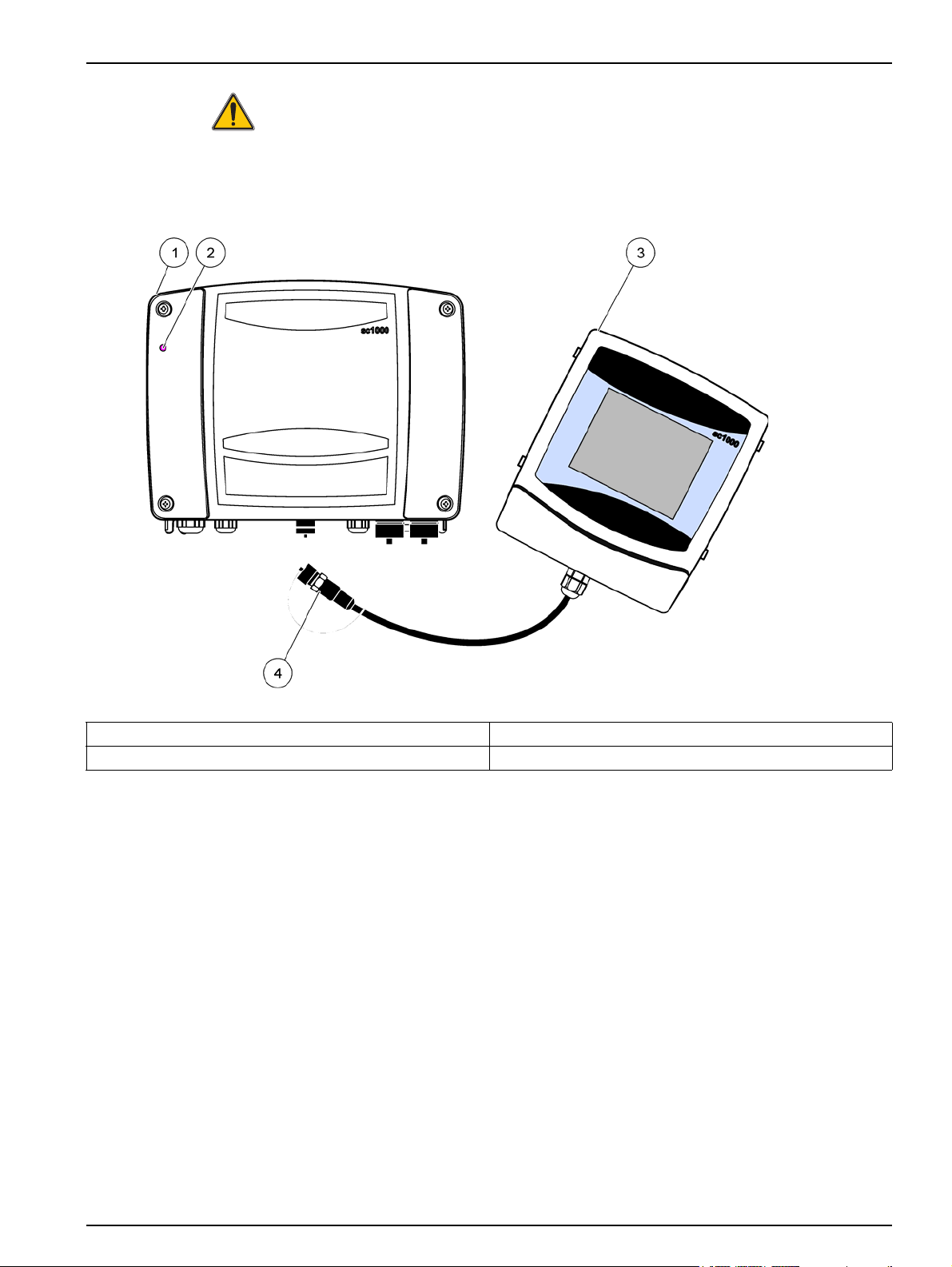
Figure 1 Probe module with display module
1 Probe module 3 Display module
2 LED indicator 4 Connector, display module to probe module
11
Page 14
Installation
3.1.1 Controller dimensions
12
Figure 2 sc1000 controller dimensions
Page 15
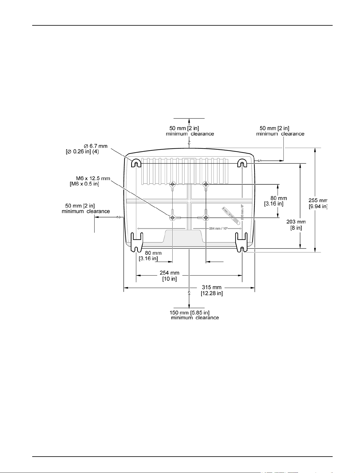
3.2 Mounting the controller
3.2.1 Wall mounting
Leave a minimum of 5 cm (2 in.) of space at the top and sides for cooling purposes and
display module installation. Leave a minimum of 15 cm (6 in.) of space underneath for the
cable connections. Refer to Figure 3 for proper wall mounting dimensions.
1. Install four bolts into the wall.
2. Hang the sc1000 controller over the bolts and attach the supplied washers and
hand-tighten the two bottom bolts.
Installation
Figure 3 sc1000 controller mounting features
13
Page 16
Installation
3.2.2 Vertical or horizontal pipe mounting
Refer to Figure 4 for mounting descriptions. For more information on pipe mounting refer
to the instructions supplied with the mounting kit.
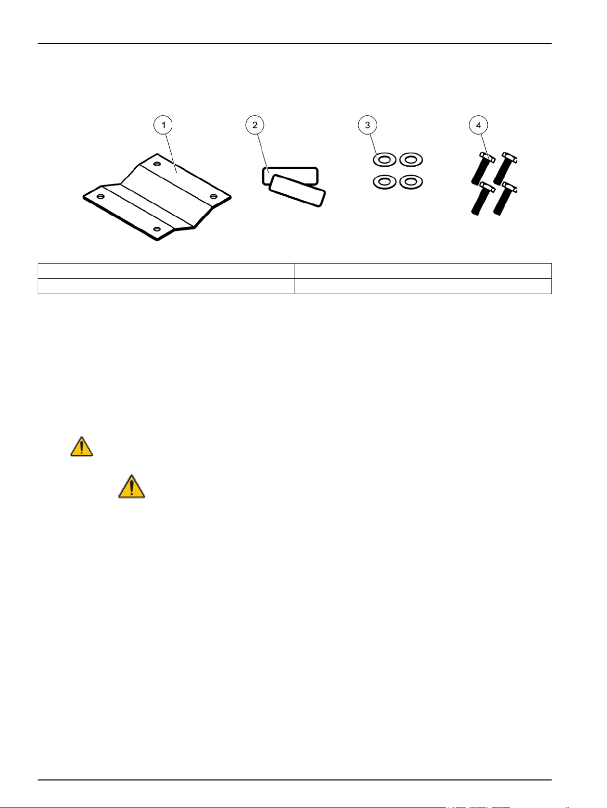
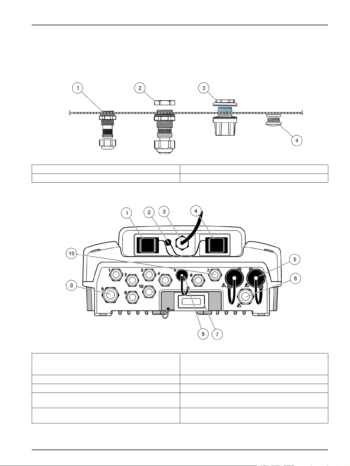
Figure 4 Pipe mounting hardware
1 Bracket, pipe mount (LZY001) 3 Flat washer (4x) (LZX948)
2 Rubber pads (8x) (LZX948) 4 Hexagon head screw (4x) M5 x 30 mm (LZX948)
3.2.3 Panel Mounting
Refer to the instruction sheet supplied with the mounting hardware for installation
instructions.
3.2.4 Sun-shield
The optional sun-shield is highly recommended for all outdoor installations. Refer to the
instruction sheet supplied with the sun-shield for installation instructions.
3.3 Wiring safety information
DANGER
Electrocution hazard. Always disconnect power to the instrument when making
electrical connections.
When making any wiring connections to the sc1000 Controller, the following warnings
and notes must be adhered to, as well as any warnings and notes found throughout the
individual installation sections. For more safety information refer to Safety information on
page 9.
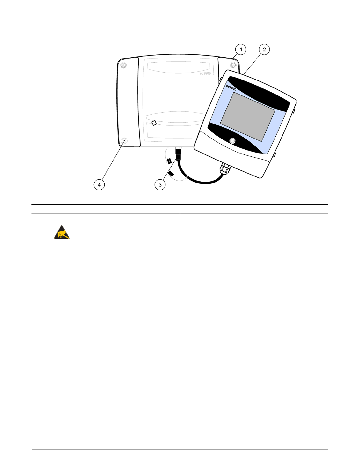
Remove the display module before performing any wiring tasks (Figure 5).
14
Page 17
Installation
Figure 5 Remove display module and probe module cover
1 Probe module cover 3 Connector, display module
2 Display module 4 Screw (4x)
3.3.1 Electrostatic discharge (ESD) considerations
Important Note: To minimize hazards and ESD risks, maintenance procedures not
requiring power to the analyzer should be performed with power removed.
Delicate internal electronic components can be damaged by static electricity, resulting in
degraded instrument performance or eventual failure. The manufacturer recommends
taking the following steps to prevent ESD damage to your instrument:
• Before touching any instrument electronic components (such as printed circuit cards
and the components on them) discharge static electricity from your body. This can be
accomplished by touching an earth-grounded metal surface such as the chassis of an
instrument, or a metal conduit or pipe.
• To reduce static build-up, avoid excessive movement. Transport static-sensitive
components in anti-static containers or packaging.
• To discharge static electricity from your body and keep it discharged, wear a wrist
strap connected by a wire to earth ground.
• Handle all static-sensitive components in a static-safe area. If possible, use anti-static
floor pads and work bench pads.
15
Page 18

Installation
3.4 Electrical installation
DANGER
Electrocution hazard. Only qualified personnel should conduct the installation
tasks described in this section of the manual.
DANGER
Electrocution hazard. Always install a ground fault interrupt circuit (GFIC)/ residual
current circuit breaker (rccb) with a maximum trigger current of 30 mA. If installed
outside, provide overvoltage protection.
If installed outdoors, provide overvoltage protection between the power and the sc1000
controller. Make sure the data and power cables do not cause tripping and do not contain
any sharp bends. Refer to Figure 7 for housing breakout information.
High-voltage wiring for the controller is conducted behind the high voltage barrier in the
controller enclosure. The barrier must remain in place unless a qualified installation
technician is installing wiring for power, alarms, or relays. See Figure 9 for barrier
removal information.
The instrument can be wired for line power by hard-wiring in conduit or by wiring to a
power cord if allowed by local electrical code. A local disconnect designed to meet local
electrical code is required and must be identified for all types of installation.
Do not connect the electrical power supply to the AC power until the sc1000 controller
has been fully wired, fused, and the high voltage barrier and probe module cover have
been replaced.
3.4.1 Installation in hard-wired applications
In hard-wired electrical applications, the power and safety ground service drops for the
instrument must be 18 to 12 AWG. A sealing-type strain relief must be used to maintain
the IP65 environmental rating. See Figure 6 for strain relief and conduit opening sealing
plug assembly. See Figure 13 for wiring information.
Note: There is no on/off switch to disconnect the probe module from AC Power.
16
Page 19
3.4.2 Installation using a power cord
A sealing-type strain relief to maintain the IP65 environmental rating and a power cord
less than 3 meters (10 feet) in length with three 18-gauge conductors (including a safety
ground wire) can be used, see Section 9 on page 129. See Figure 6 for strain relief and
conduit opening sealing plug assembly. See Figure 14 on wiring information.
Figure 6 Using the optional strain relief and conduit plug
1 Strain relief, small 3 Conduit
2 Strain relief, large 4 Plug, sealing
Installation
Figure 7 Housing breakouts
1 Storage card slot 6 AC power connection (PS1), strain relief M20 x 1.4 mm
(4-8 mm cable diameter), conduit, different version of
power cord (optional)
2 GSM antenna connection (optional) 7 Network interface
3 Cable assembly for connection to probe module 8 Cable assembly for connection to display module
4 Service port 9 Relay connection—2.19 mm for conduit or strain relief
M20x1.5 with union mount (9–13.5 mm cable diameter)
5 Power outlet for 100–240 VAC powered sc probes 10 Configured as either sc probe connectors or
strain-reliefs, M16 x 1.5 (5–6 mm cable diameter)
17
Page 20
Installation
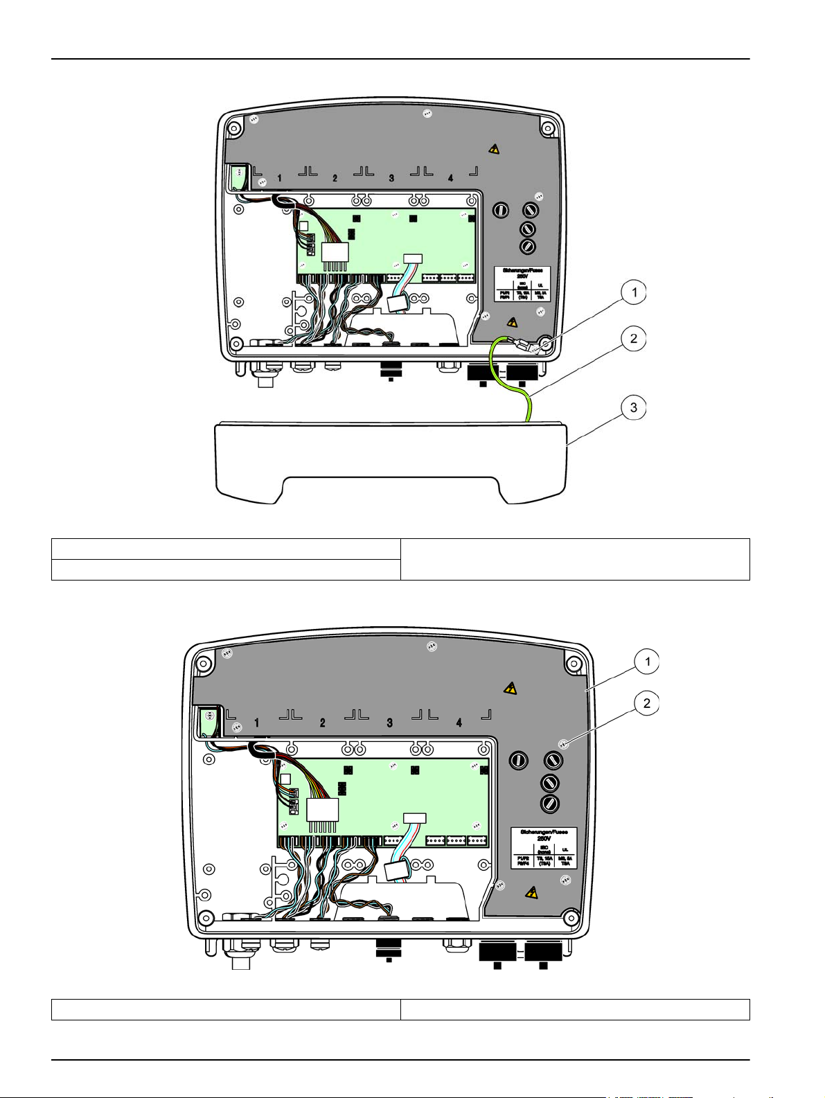
Figure 8 Removing the probe module cover
1 Ground screw 3 Probe module cover
2 Ground wire
Figure 9 Removing high voltage barrier
1 High voltage barrier 2 Screw (6x)
18
Page 21
Installation
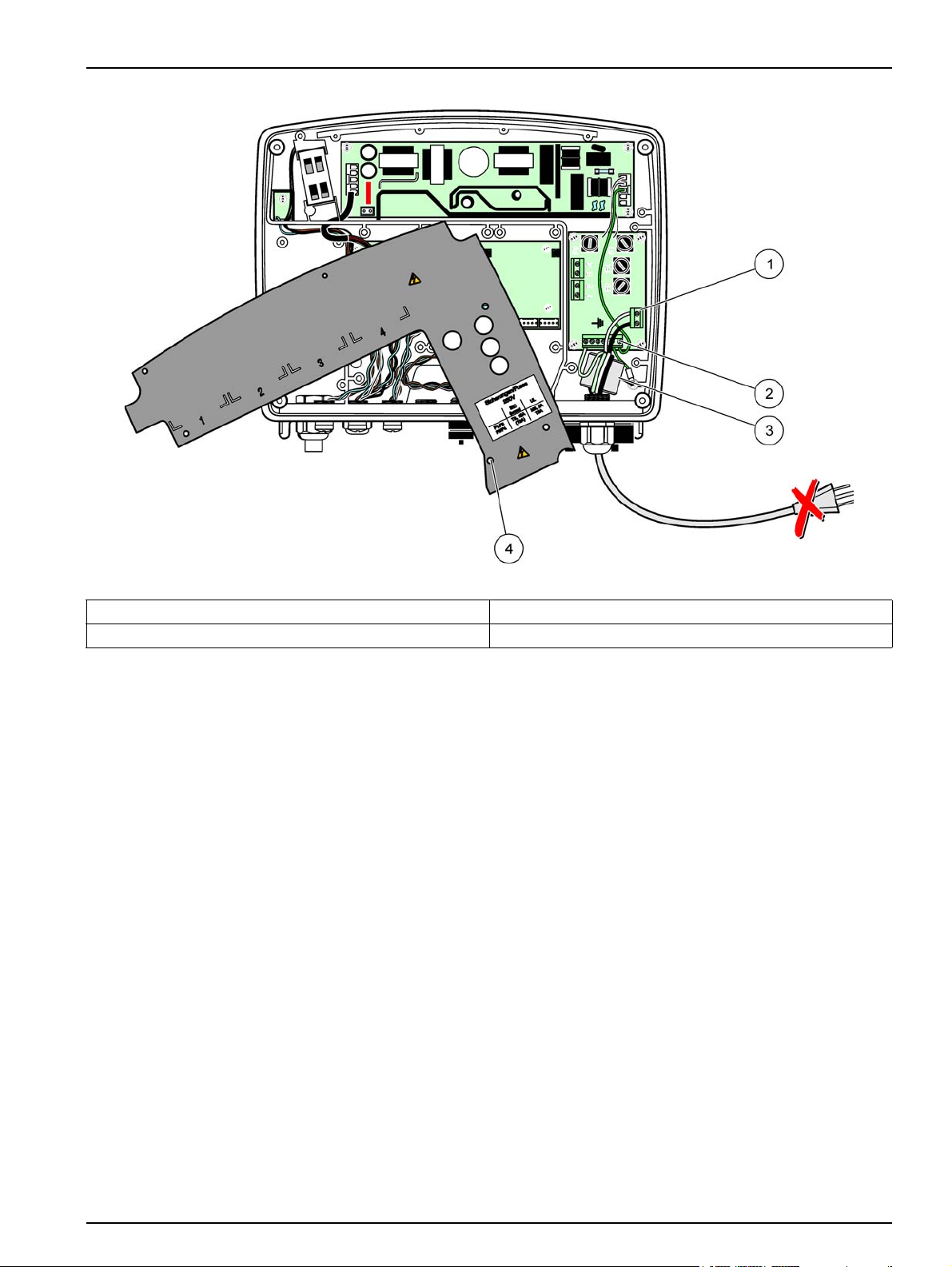
Figure 10 Wiring for power
1 AC power connections 3 Ferrite will fit snugly in this area
2 Earth Ground Connections 4 Barrier should fit easily into position
19
Page 22
Installation
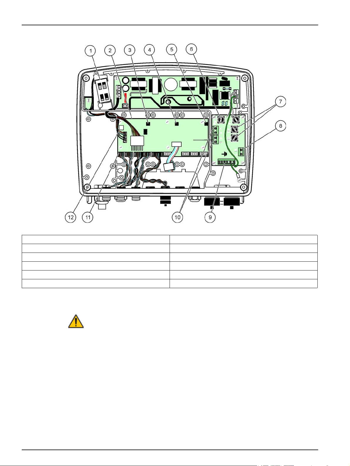
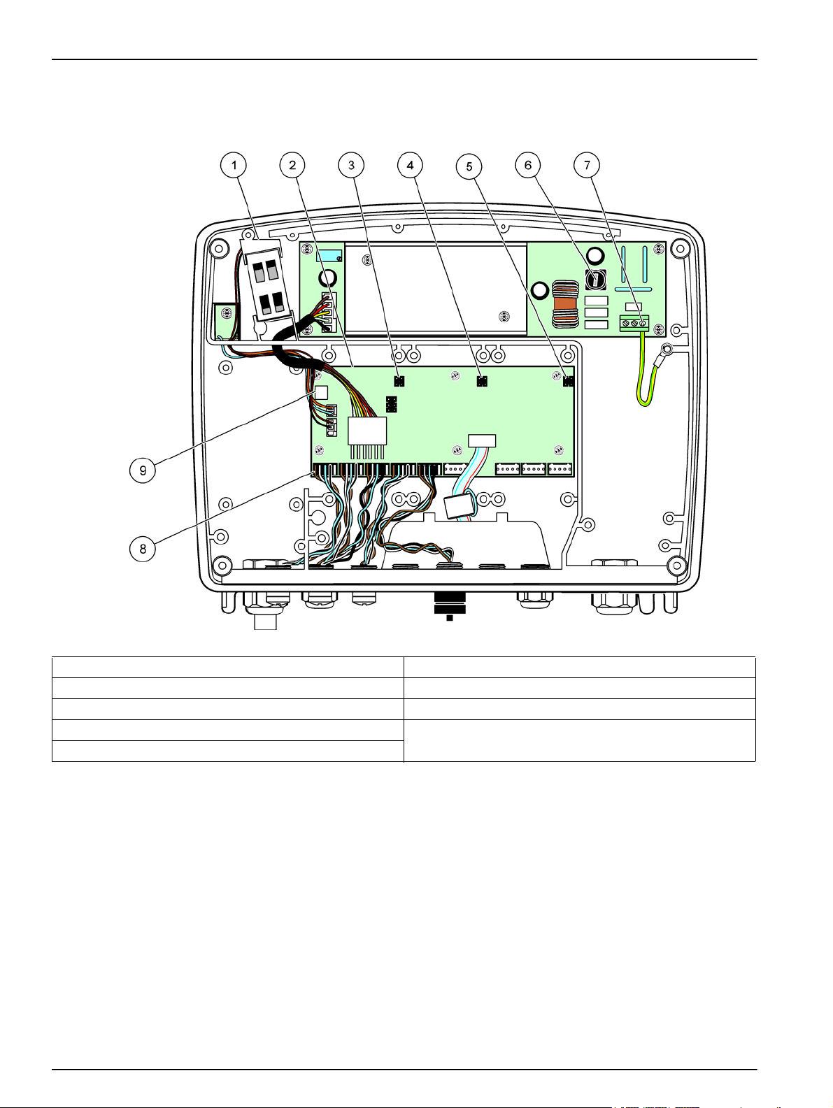
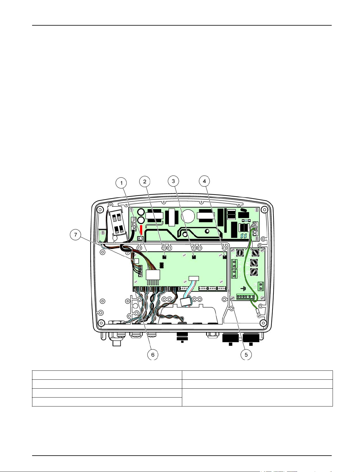
Figure 11 Inside the AC probe module
1 Fan 7 Fuse (2x), F3 and F4: T 8A; 100–240 V, slow-blow
2 Main circuit board 8 AC power connections
3 Connector for expansion slot 9 Earth ground connection
4 Connector for expansion slot 10 Power outlet connection
5 Connector for expansion slot 11 Probe connections
6 Fuse (2x), F1 and F2: M 3.5A, medium blow 12 Relay card connection
3.4.3 Wiring for AC power at the controller
DANGER
Electrocution hazard. Failure to connect to a good low impedance Protective Earth
ground can result in both a shock hazard and poor performance against
electro-magnetic interferences.
1. Obtain appropriate fittings with IP65 environmental rating.
2. Remove the display module from the probe module (Figure 5).
3. Remove the four screws securing the probe module front cover. Open the probe
module and disconnect the chassis ground connection from the ground stud to the
cover.
4. Remove the six screws from the high voltage barrier and remove the barrier.
20
5. Insert the wires through the PG1 opening and strain relief fitting or conduit hub.
Tighten the strain relief if used, to secure the cord.
Page 23
Installation
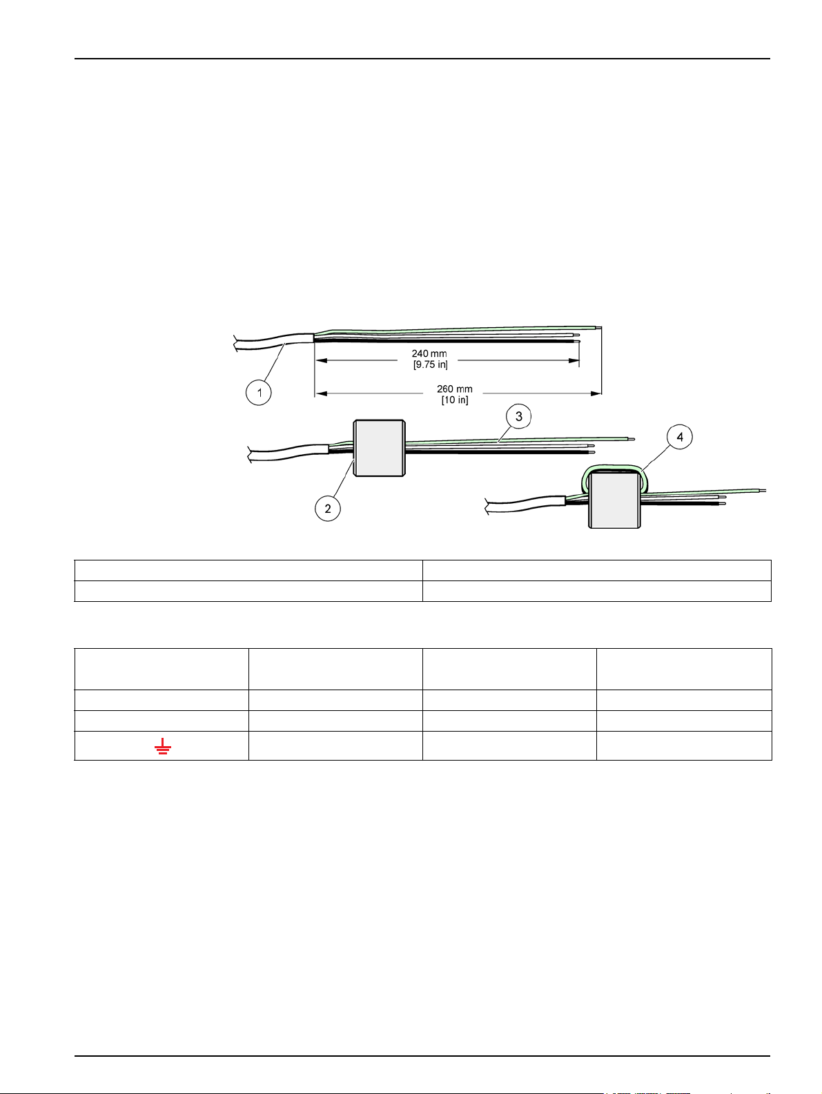
6. Strip the cable outer insulation 260 mm (10 in.) (Figure 12). Shorten all wires except
the earth wire 20 mm (0.78 in.), so the earth cable is 20 mm (0.78 in.) longer than the
other cables.
7. Feed the stripped power cable through the ferrite core twice (Figure 12) and wire into
the terminal as shown in Table 1 and Figure 10. Tug gently after each insertion to
make sure that the connection is secure.
8. Seal any unused openings in the controller box with conduit opening sealing plugs.
9. Install the high voltage barrier.
10. Connect the chassis ground connection to the ground stud of the probe module
cover.
11. Install the probe module cover and screw into place.
Figure 12 Proper wire preparation and ferrite core wiring
1 Power cable wire preparation 3 Power cable wires
2 Ferrite core 4 Power cables wrapped around ferrite core
Table 1 AC power wiring information
Terminal number Terminal description
L Hot (L1) Black Brown
N Neutral (N) White Blue
Protective Earth (PE) Green Green w/yellow tracer
Wire color code for North
America
Wire color code for Europe
21
Page 24
Installation
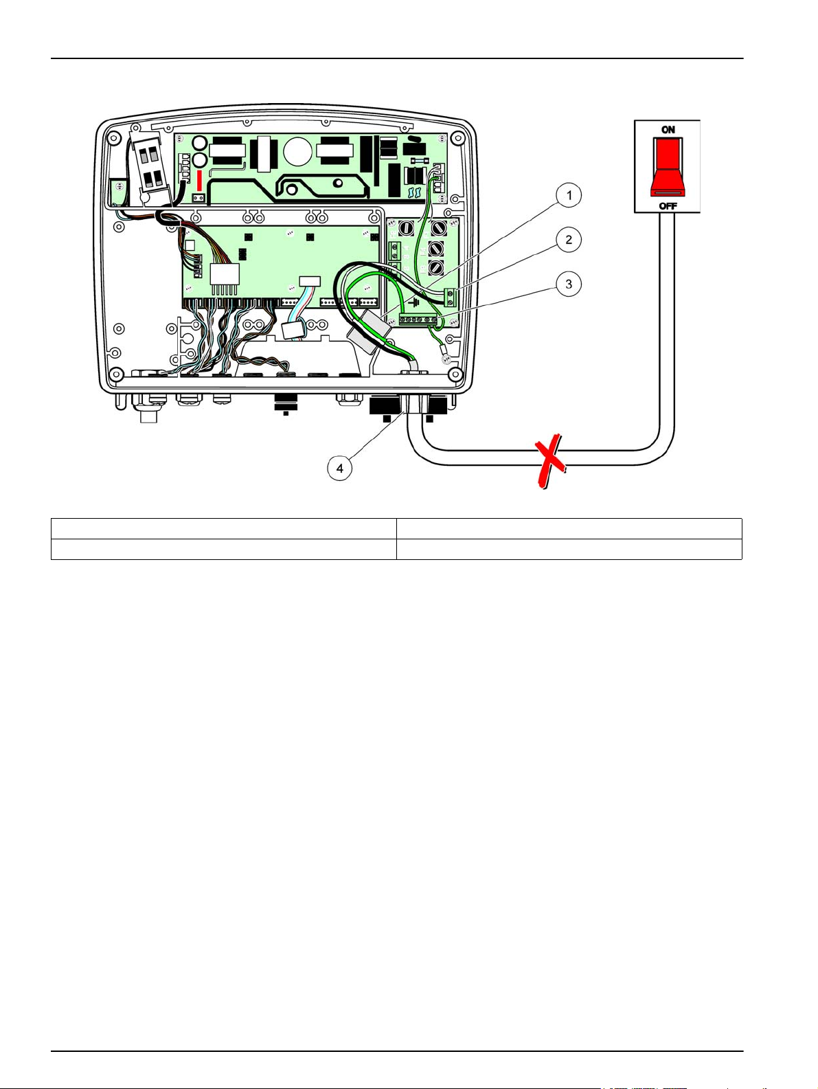
Figure 13 Hard-wired installation
1 Ferrite core (Electromagnetic interference device) 3 Earth ground connection
2 AC power connections (optional, LZX970) 4 Conduit hub, strain relief
22
Page 25
Installation
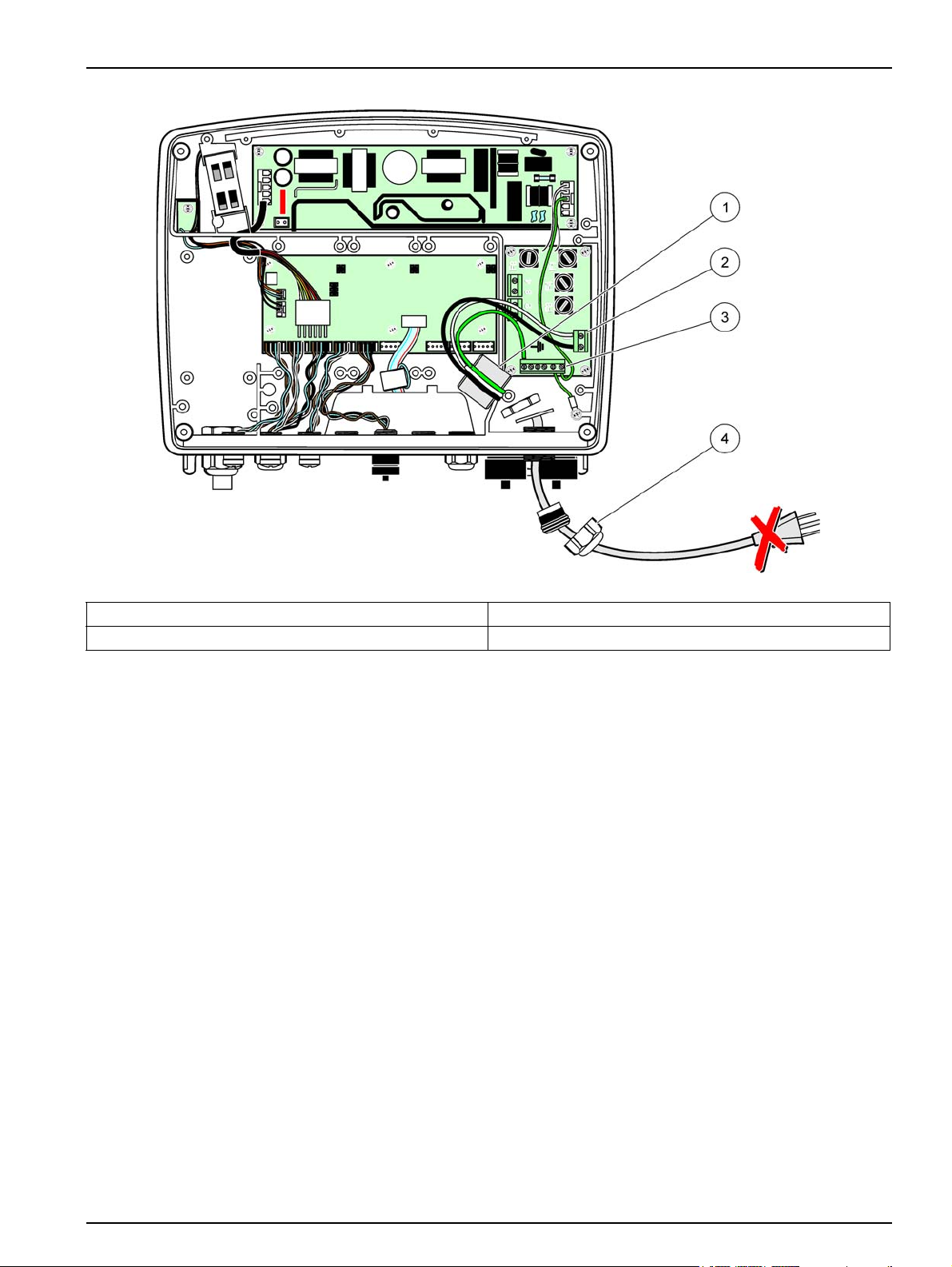
Figure 14 Installation with power cord
1 Ferrite core (Electromagnetic Interference Device) 3 Earth ground connection
2 AC power connections 4 Strain relief
23
Page 26
Installation
3.4.4 Wiring for 24 VDC power at the controller
Important Note: The AC power outlets cannot be used with the 24 VDC power supply.
Figure 15 Inside the 24 VDC probe module
1 Fan 6 Fuse, T 6.3A, slow-blow
2 Main circuit board 7 24 VDC power connections
3 Connector for expansion slot 8 Probe connections
4 Connector for expansion slot 9 Relay card connection
5 Connector for expansion slot
24
Page 27
Installation
Figure 16 Wiring for 24 VDC power
1 24 VDC power terminal block 3 Strain relief
2 Cable
Table 2 DC power wiring information
Terminal number Terminal description
+ +24 VDC Red Brown
- 24 VDC Return Black Blue
Protective Earth (PE) Green Green w/yellow tracer
Wire color code for North
America
Wire color code for Europe
25
Page 28

Installation
3.5 DIN rail expansion modules
CAUTION
The expansion modules for control cabinet installation use the 24 VDC power
supply in the control cabinet. Make sure that the correct power supply is provided.
Install a residual current circuit breaker. The modules have an environmental rating
of IP20 and must always be mounted in an enclosure suitably rated for power and
environment.
The sc1000 controller can be expanded with DIN rail expansion modules.
The following DIN rail module options can be installed:
• Base module (for connecting power, sc1000 network and display module)–The base
module is required for the installation of expansion modules on the control cabinet.
• Relay card with 4 relays
• mA output card with 2 outputs
• mA input card with 2 inputs (analog or digital)–One base module can provide up to
2000 mA of power to the other modules connected to it on the DIN rail.
The total number of modules that can be connected together is limited by the power
supply from the base module. Up to 13 communication modules can be attached to each
base module. When more than 13 communication modules are needed, a second base
module must be connected through the sc1000 network.
Refer to Appendix A on page 141 for more information about the DIN rail expansion
modules.
26
Page 29
3.6 Expansion cards
The sc1000 controller can be expanded with internal plug-in expansion cards. Each
expansion component can be identified with its serial number on the sc1000 network and
programmed as required. The serial number is located on the card.
It may be necessary to remove an existing expansion card, if the expansion card is
blocking access to certain connectors. Refer to section 3.6.6 on page 37 for more
information.
When an instrument is ordered, it comes pre-installed with the appropriate plug-in
expansion cards. The following options can be connected:
• Relay card with 4 relays
• Digital field-bus cards (Modbus (RS485), Modbus (RS232), Profibus DP)
• mA output card with 4 outputs
• mA input card with 4 inputs (analog or digital)
• sc-probe connectors
Installation
Figure 17 Expansion card main circuit board connections
1 Main circuit card 5 Mounting holes, input cards (4 each)
2 Connector for expansion slot #2 6 sc probe connections
3 Connector for expansion slot #3 7 Relay card connection
4 Connector for expansion slot #4
27
Page 30
Installation
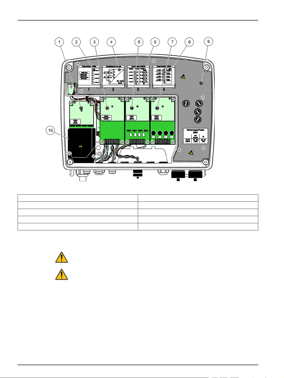
Figure 18 Expansion card ports
1 Relay card 6 mA output or input wiring information
2 Relay wiring information 7 mA output or input card
3 Field-bus or mA output or input card 8 mA output or input wiring information
4 Field-bus or mA output or input card wiring information 9 Main high voltage barrier
5 mA output or input card 10 Relay voltage barrier
3.6.1 Relay card connections
DANGER
Electrocution hazard. Relays must either be wired as low or high voltage.
DANGER
Fire hazard: Relay loads must be resistive. User must externally limit current to the
relays to 5 Amps by use of a fuse or breaker.
The relay connector accepts 18–12 AWG wire (as determined by load application). Wire
gauge less than 18 AWG is not recommended.
If the instrument is equipped with the relay card option, the instrument will include 4
relays, each with one change over contact. In this configuration, steps 3, 4 and 6 in To
make a relay card connection are not applicable.
The relays can switch maximum 250 VAC, 5A. Each relay can be configured for different
applications.
28
Page 31

Installation
To make a relay card connection
For instruments not equipped with a relay card, do the steps listed below to make relay
card connections.
1. Remove power from the instrument. Remove the probe module cover.
2. Remove the screws on the plastic relay cover. Remove the plastic cover.
3. Connect the relay card to the appropriate slot (Figure 18). Use a magnetic
screwdriver to secure the four phillips-head screws to the card. It is easier to connect
the cards with the module in its normal vertical mounted position, rather than laid
horizontally on a bench.
4. Install the card connector to the appropriate connection on the main circuit board
(Figure 17).
5. Feed the cable through the base of the module and properly prepare and insert each
wire (Figure 19) into the terminal according to Figure 20/Table 3 and Figure 21/Table
4. Tug gently after each insertion to make sure that the connection is secure.
6. Write the serial number from the rating plate on the supplied sticker and attach it to
the main high voltage barrier (Figure 18). This serial number is the same internal
address of the card on the network.
7. Install the relay and probe module cover.
After installation and connection of a plug-in expansion card, the card must be configured
to the system. For relay card setup instructions, refer to section 6.3.3 on page 87.
Figure 19 Proper wire preparation and insertion
1 Strip ¼-in (64 mm) of insulation. 2 Seat insulation against connector with no bare wire
exposed.
Figure 20 Relay card (YAB022, normally closed)
1 Terminal Block–Refer to Table 3 for terminal assignments.
29
Page 32

Installation
Table 3 Relay card (YAB022, normally closed) terminal assignments
Terminal Designation Relay 1–4
1
2
3
4
5
6
7
8
Relay 1 (normally closed contacts)
Relay 2 (normally closed contacts)
Relay 3 (normally closed contacts)
Relay 4 (normally closed contacts)
Maximum switching voltage:
250 VAC;
125 VDC
Maximum switching current:
250 VAC, 5A
125 VAC, 5A
30 VDC, 5A
Maximum switching power:
1500 VA
150 W
Figure 21 Relay card (YAB076, change over)
1 Conductor (Pull to remove from the board, when wiring
outside devices to terminal connectors)
2 Relay 1 5 Relay 12
3 Relay 7 6 Terminal Block – Refer to Table 4 for terminal
4 Relay 6
assignments
30
Page 33

Table 4 Relay card (YAB076, change over) terminal assignments
Terminal Designation Relay 1–4
1 Relay 1 (normally closed contacts)
2 Relay 1 (common)
3 Relay 1 (normally opened contacts)
4 Relay 2 (normally closed contacts)
5 Relay 2 (common)
6 Relay 2 (normally opened contacts)
7 Relay 3 (normally closed contacts)
8 Relay 3 (common)
9 Relay 3 (normally opened contacts)
10 Relay 4 (normally closed contacts)
11 Relay 4 (common)
12 Relay 4 (normally opened contacts)
Maximum switching voltage:
250 VAC;
125 VDC
Maximum switching current:
250 VAC, 5A
125 VAC, 5A
30 VDC, 5A
Maximum switching power:
1500 VA
3.6.2 Input card connections
With the input card, the sc1000 receives external analog signals (0–20 mA/4–20mA) and
digital signals. The signals can be scaled as required and given names, parameters, and
units.
Installation
150 W
To make an input card connection:
1. Remove power from the instrument. Remove the probe module cover.
2. Connect the input card to the appropriate slot (Figure 18). Use a magnetic
screwdriver to secure the four screws to the card.
3. Install the card connector to the appropriate connection on the main circuit board
(Figure 17)).
Note: The inputs can be switched between analog and digital using the jumper switches. Place the
jumper on both pins to switch to digital, place the jumper on one pin to switch to analog.
4. Feed the cable through the base of the module and properly prepare and insert each
wire into the terminal according to Figure 22 and Table 5. Tug gently after each
insertion to make sure that the connection is secure.
5. Write the serial number from the rating plate on the supplied sticker and attach it to
the main high voltage barrier (Figure 18).
6. Install the probe module cover.
After installation and connection of a plug-in expansion card, the card must be configured
to the system. For input card setup instructions, refer to section 6.3.2 on page 83.
31
Page 34

Installation
1 Jumper switches
Digital input=Jumper closed
Analog input=Jumper opened
Figure 22 Input card (YAB018) cable connections and jumper setting
2 Terminal block– Refer to Table 5 for terminal assignments.
Table 5 Input card (YAB018) terminal assignments
Terminal Designation
1 Input 1 +
2 Input 1 –
3 Input 2 +
4 Input 2 –
5 Input 3 +
6 Input 3 –
7 Input 4 +
8 Input 4 –
9 PE (Protective earth)
32
Page 35

3.6.3 Output card connections
If the instrument is equipped with the output card option, the mA output card supplies up
to 4 analog (0–20 mA/4–20 mA) signals into an impedance of max. 500 Ohm.
Note: The sc1000 mA output card cannot be used to provide power to a 2-wire (loop-powered)
transmitter.
To make an output card connection:
1. Remove power from the instrument. Remove the probe module cover.
2. Connect the output card to the appropriate slot (Figure 18). Use a magnetic
screwdriver to secure the four screws to the card.
3. Install the card connector to the appropriate connection on the main circuit board
(Figure 17).
4. Feed the cable through the base of the module and properly prepare and insert each
wire into the terminal according to Figure 23 and Table 6. Tug gently after each
insertion to make sure that the connection is secure.
5. Write the serial number from the rating plate on the supplied sticker and attach it to
the main high voltage barrier (Figure 18).
6. Install the probe module cover.
Installation
After installation and connection of a plug-in expansion card, the card must be configured
to the system. For output card setup instructions, refer to section 6.3.1 on page 78.
Figure 23 Output card (YAB019) cable connections
1 Terminal Block–Refer to Table 6 for terminal assignments.
Table 6 Output card (YAB019) terminal assignments
Terminal Designation
1 Output 1+
2 Output 1 –
3 Output 2 +
4 Output 2 –
5 Output 3 +
6 Output 3 –
7 Output 4 +
8 Output 4 –
9 Shield (Connected to protective earth)
33
Page 36

Installation
3.6.4 Modbus card connections
Modbus RS485 (YAB021) and Modbus RS232 (YAB047) are available. For more detailed
information refer to the bus system manual.
To make a Modbus card connection:
1. Remove power from the instrument. Remove the probe module cover.
2. Connect the Modbus card to the appropriate slot (Figure 18). Use a magnetic
screwdriver to secure the four screws to the card.
3. Install the card connector to the appropriate connection on the main circuit board
(Figure 17).
4. Feed the cable through the base of the module and properly prepare and insert each
wire into the terminal according to Figure 24/Table 7 and Figure 25/Table 8.
5. Write the serial number from the rating plate on the supplied sticker and attach it to the
main high voltage barrier (Figure 18).
6. Install the probe module cover.
After installation and connection of a plug-in expansion card, the card must be configured
to the system. For Modbus card setup instructions, refer to section 6.3.4.2 on page 111.
)
Figure 24 Modbus RS485 (YAB021) card connections
1 Card (Reverse side) 3 Jumper 1&2 unplugged for full duplex (4-wire)
2 Jumper 1&2 plugged for half duplex (2-wire) 4 Terminal block (Refer to Table 7 for terminal
assignments)
Table 7 Modbus RS485 card (YAB021) terminal assignments
Terminal Modbus RS485 designation with 4 wires Modbus RS485 designation with 2 wires
1 Not Used Not Used
2 Not Used Not Used
3 Output – –
4 Output + +
5 Input – –
6 Input + +
7 Shield (connected to Protective Earth) Shield (connected to Protective Earth)
34
Page 37

Figure 25 Modbus RS232 (YAB047) card connections
1 Terminal Block (Refer to Table 8 for terminal assignments)
Installation
Table 8 Modbus RS232 card (YAB047) terminal assignments
Terminal Modbus RS232 designation
1 Not Used
2 Ground
3 Not Used
4 TXD (Transmitting line Modbus Card)
5 Not Used
6 RXD (Receiving line Modbus Card)
7 Not Used
3.6.5 Profibus DP card connections
Refer to the documentation supplied with the Profibus DP card for more information.
Refer to the appropriate probe manual for operating instructions, instrument profiles,
and GSD files. Refer to the company web site for the latest GSD files and documentation.
To make a Profibus card connection:
1. Remove power from the instrument. Remove the probe module cover.
2. Connect the Profibus card to the appropriate slot (Figure 18). Use a magnetic
screwdriver to secure the four screws to the card.
3. Install the card connector to the appropriate connection on the main circuit board
(Figure 17).
4. Feed the cable through the base of the module and properly prepare and insert each
wire into the terminal according to Figure 26 and Table 9. Make sure that the shield is
connected to a threaded spacer on the board.
5. Write the serial number from the rating plate on the supplied sticker and attach it to
the main high voltage barrier (Figure 18).
6. Install the probe module cover.
35
Page 38

Installation
After installation and connection of a plug-in expansion card, the card must be configured
to the system. For Profibus card setup instructions refer to section 6.3.4.1 on page 109.
Figure 26 Profibus DP card (YAB020) connections
1 Network termination activated, last device on network 3 Terminal Block – Refer to Table 9 for terminal
2 Network termination deactivated, other devices on network
after this device.
assignments.
Table 9 Profibus DP card (YAB020) terminal assignments
Terminal Designation
1 Not used
2 Not used
3 B in (wire color red)
4 A in (wire color green)
5 B out (wire color red)
6 A out (wire color green)
7 PE (Protective Earth)
36
Page 39

3.6.6 Remove/Replace an expansion card
It may be necessary to remove an existing expansion card if probe connectors are
obstructed.
Important Note: The compact connectors are a very tight fit and the connections can
easily break off. Do not apply excessive force when fitting and removing the compact
connectors.
To remove/replace an expansion card:
1. Delete the card in the sc1000 controller. Refer to section 6.3.6 on page 115.
2. Remove power from the instrument. Remove the probe module cover.
3. Disconnect all cable connections to the card.
4. Remove the screws securing the card and remove the card.
5. Replace the card and configure the card.
3.7 Install an sc1000 network (sc1000 bus connection)
An sc1000 network connects up to 32 participants (Figure 27). Participants are defined as
anything attached to the network including probes and optional cards but not counting the
display module or probe modules. Only one display module is allowed for one sc1000
network.
Installation
Each probe module has an sc1000 network interface (Figure 28). Use the sc1000
network cable and the sc1000 network connector to set up a network. Suitable cable and
network connector is available from the manufacturer.
Figure 27 sc1000 network
1 Profibus/Modbus connection 4 Probe module
2 sc1000 controller (Display and probe module) 5 Probe
3 sc1000 bus connection
37
Page 40

Installation
Figure 28 Plugging the network connector to the network interface
1 Probe module 3 sc1000 network connector
2 sc1000 network interface 4 sc1000 network interface cover
3.7.1 sc1000 network connections
To attach a network connector:
1. Strip the insulation from the communication cable (Figure 29).
2. Feed the cable through the union nut, rubber seal, and connector housing
(Figure 31).
3. Connect the cable to the network connector circuit board as shown in Table 10.
Network Connector Assembly
4. Place the circuit board with the cable connected in the bottom part of the metal
frame.
5. Tighten the cable connector.
6. Place the top of the metal frame on the bottom and press together.
7. Feed the frame into the sc1000 connector. The frame will only fit in one position. If
necessary, rotate the frame.
8. Attach the circuit board and the frame to the front with the two self-tapping screws
provided.
38
Page 41

Installation
9. If necessary, set the terminating resistor.
Note: When using the connector with the last module on the network segment, one union nut
remains unused. Seal the union nut with the plug supplied. Refer to Figure 31.
10. If this connector is the end of the network, insert the rubber seal in the connector.
11. Tighten the union nut by two turns.
12. Insert the sealing plug in the unused union nut and rubber seal.
13. Tighten the union nut.
14. Set a terminating resistor at the last network connector to the ON position (see
Figure 32 and Table 11).
15. Plug the connector into the probe module.
Figure 29 Removing the insulation from the communication cable
1 Cable, 2-conductor 3 Circuit card/bottom shell, cable, and cable clamp
subassembly
2 Connector, (network connector printed circuit board) 4 Network cable installed in connector
Table 10 Communication connector terminal assignments
Connection Cable Signal Length
1A Incoming or last device A
1B Incoming or last device B
2A To further devices A
2B To further devices B
Note: If the network connector is terminated, 2A and 2B are set to off.
25 mm (1 in.)
35 mm (1.4 in.)
39
Page 42

Installation
Figure 30 Network connector components
1 Housing, network connector 7 Insert, plastic label (network connector housing)
2 Network connector printed circuit board with shell bottom 8 Not used
3 Shell, top 9 Plug, rubber, cord grip
4 Screws, self-tapping (2x) 10 Seal, cord grip (2x)
5 Clamp, network cable(s) 11 Cord grip (2x)
6 Screw, pan head
40
Page 43

Installation
Figure 31 Connecting the network connector to the sc1000 network terminating resistor
1 Shell, bottom 6 Housing, network connector
2 Network connector printed circuit board with shell bottom 7 Seal, cord grip
3 Clamp, network cable(s) 8 Cord grip
4 Screw, pan head 9 Plug, rubber, cord grip
5 Cables, network
1
Route cables as shown and make sure that clamp is fastened securely.
2
Use this plug if the cord grip is not used, refer to inset in Figure 31.
1
10 Screws, self-tapping (2x)
2
41
Page 44

Installation
Figure 32 Setting a terminating resistor (DIP switch in the connector)
1 Housing, network connector 3 Dip switch (note position assignments as shown)
2 Cap, rubber 4 Insert, plastic label
Table 11 Communication connector terminating resistor (communication termination)
Switch setting Terminating resistors Connection 2
On Enabled Disabled
Off Disabled Enabled
Note: The DIP switch can also be operated when the connector is fitted. The OFF and ON switch
positions are also printed on the connector housing. Use the switch for commissioning and
troubleshooting segment by segment. Shut down the segments one by one and check for function
and errors.
42
Page 45

3.8 Connect probes to the sc1000 controller
All sc series probes can be used on the sc1000 controller.
Important Note: Plan the route for the probe cable and lay the data and power cables so
that they do not cause a trip hazard and the cables do not have any sharp bends.
For details on the installation and operation of the probe, refer to the appropriate probe
manual.
3.8.1 Connect the probe data cable
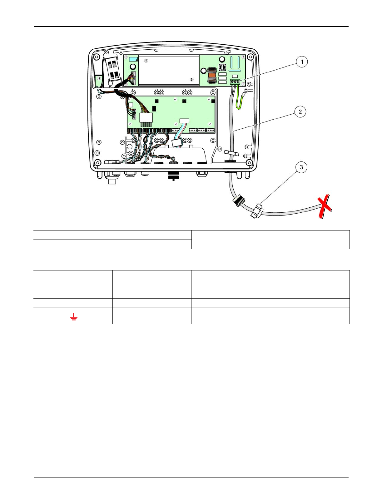
1. Unscrew the protective cover on the controller socket (Figure 33). Retain the
protective cover. When you remove the probe, re-fit the protective cover.
2. Align the connector plug with the socket, pay attention to the orientation of the
connector lugs.
3. Hand-tighten the union nut.
Note: Keep the middle connection of the probe module free. Use the free port to connect the display
module to each probe module in a network.
Installation
Figure 33 Removing the protective cover
1 sc probe connection 2 Protective cover
43
Page 46

Installation
3.8.2 Add probe connections
When all probe connectors on the sc1000 controller are already in use for probes, more
probe connectors can be added (max. 8 probe connectors). It may be necessary to
remove an existing expansion card if accessibility to probe connectors is obstructed (refer
to section 3.6.6 on page 37).
Note: If a probe module has the maximum number of probes, more probes may be added to the
system by purchasing additional probe modules.
To add probe connections:
1. Remove power from the instrument. Open the probe module cover.
2. Remove the fitting or plug from a spare probe socket hole.
3. Screw a new probe connector into the housing and connect the probe connector to a
probe connection on the main circuit board. Any available probe connector can be
used.
4. Assemble the housing.
3.8.3 Connect AC powered sc probes
Note: AC power outlets can only be connected when a 100 V–240 V power supply is fitted in the
sc1000 controller.
Most sc-probes draw power directly from the sc probe connection. However, certain sc
probes may require supplemental 100–240 VAC power (e.g., to run pumps or heating
elements). These AC powered sc-probes have two cables that connect to an sc1000
probe module: a standard sc-probe connector and a special connector for drawing
AC power from the probe module.
To connect AC powered probes to a probe module:
1. Unscrew the cover on the AC power outlet.
2. Connect the power connector from the analysis instrument to one of the
AC power outlets.
3. Connect the sc-probe connector to any available sc-probe socket.
3.9 Service port connection (LAN connection)
The service port of the sc1000 controller is a 10 MB/s Ethernet interface at the display
module (Figure 7). To use the service port, connect an Ethernet cross-over cable from a
computer to the service port. The Ethernet connection can be used to run all sc1000
controller functions or calibrate the probes through any web browser.
Configure the network adapter inside the computer to communicate with the sc1000
controller.
Important Note: It is recommended to use an external Ethernet USB network adapter as
an interface to the sc1000 controller. The use of a second network adapter makes sure
that the sc1000 controller connection does not have any impact to the default local area
network (LAN) connection (for example the regular office network).
44
To setup and prepare a LAN connection, refer to section 5.13.1 on page 67 and
section 5.13.2 on page 67.
Page 47

3.10 GSM modem connection
The display module can optionally contain a built-in tri-band modem (Figure 7). The GSM
modem connection allows fully remote operation of the sc1000 controller, including
transfer of data and software updates. The GSM modem requires a SIM card, an external
GSM antenna and must meet the requirements in Table 12:
Europe USA/Canada
Installation
Table 12 GSM modem requirements
• GSM 900 or EGSM 900
(EGSM 900 = GSM 900 with expanded
frequency range)
• GSM 1800
• GSM 1900
The main modem features are:
• Maintain the sc1000 controller and sc1000 network
• Set up logging
• Download logged data
• Send out errors and warnings as a short message (SMS)
For GSM modem connection information, refer to section 5.13.3 on page 68.
3.10.1 Safety precautions
The following safety precautions must be observed during all phases of the installation,
operation, maintenance or repair of any cellular terminal or mobile phone incorporating
MC55/56. The manufacturer assumes no liability for customer failure to comply with
these precautions.
CAUTION
The GSM modem connection cannot be used in hazardous locations.
• GSM 850
• GSM 1800
• GSM 1900
The manufacturer and its suppliers reject any express or indirect guarantee for the use
with High Risk Activities.
In addition to the following safety considerations, obey all the regulations specific to the
country in which the equipment is installed.
Important Note: Cellular terminals or mobile phones operate using radio signals and
networks. These connections are not guaranteed at all times under all conditions. The
cellular terminal or mobile phone must be switched on and in a service area with adequate
signal strength.
Safety precautions for GSM modem installation
• This unit is to be installed by a trained technician employing proper installation
practices for a Radio Frequency Transmitter, including proper grounding of any
external antennas.
• Do not operate the device in hospitals and/or near medical instruments such as
cardiac pacemakers or hearing aids.
• Do not operate the device near highly combustible areas such as gas stations, fuel
depots, chemical plants and blasting works.
• Do not operate the equipment in the proximity of combustible gases, steams or dust.
45
Page 48

Installation
• Do not expose the equipment to strong vibrations or impacts.
• The GSM/GPRS modem can cause disturbances when in the proximity of television
sets, radios or PCs.
• Do not open the GSM/GPRS modem. Any change of the equipment is inadmissible
and leads to the loss of the operating permission.
• This unit is to be installed by a trained technician employing proper installation
practices for a Radio Frequency Transmitter, including proper grounding of any
external antennas.
• Using the GSM services (SMS messages, data communication, GPRS etc.) is likely to
incur additional costs from a service provider. The user is exclusively responsible for
any damages and costs incurred.
• Do not use or install this equipment in any manner other than that specified in this
manual. Inappropriate use will void the warranty.
Safety precautions for SIM card installation
• The SIM card can be taken out. Keep the SIM card out of the reach of children.
Harmful if swallowed.
• Remove all power before replacing SIM card.
Safety precautions for antenna installation
• Only use antennas, which are recommended or supplied by the manufacturer.
• The antenna must be mounted at least 20 cm away from any person.
• Do not let antenna rise up outside of protected buildings and secure antennas against
lightning!
• Remove all power before replacing an antenna.
3.10.2 SIM card requirements
The SIM card must be enabled by a provider and registered in the sc1000 controller.
The SIM card requirements are:
• GSM network supports “GSM Phase 2” (minimum)
• Includes the services “SMS (short messaging service)” and “Data Services”.
• Complies with the standards “ISO 7816-3 IC” and “GSM 11.11”.
Note: Contact the local Hach/HachLange support to discuss the SIM card and provider
requirements.
46
Page 49

3.10.3 Insert the SIM card into the display module
Important Note: The touch screen is scratch sensitive. Never place the touch screen on a
hard and scratching surface.
To insert the SIM card into the display module:
1. Disconnect the display module from the probe module.
2. Place the display module on a soft and flat base.
3. Remove the SIM card cover from the back side of the display module (Figure 34).
4. Press the button to eject the card holder for the SIM card.
5. Put the SIM card into the SIM card holder, and put the SIM card holder into the SIM
card slot.
6. Attach the cover with the two cover bolts.
7. Connect the display module to the probe module.
Installation
Figure 34 Insert the SIM card
1 Display module 3 SIM card
2 SIM card holder 4 SIM card cover
47
Page 50

Installation
3.10.4 Connect the external GSM antenna to the display module
Important Note: To guarantee proper functionality, only use the antenna that is supplied
by the manufacturer.
The standard antenna is directly attached to the GSM antenna connection at the display
module. In case of low radio signal strength, connect a roof antenna or an external
outdoor antenna.
If the distance between the position of the antenna and the display module is too long,
use one 10m extension cable (LZX955) to extend the connection.
To connect an external GSM antenna:
1. Mount all necessary components.
2. Connect an extension cable between the display module and the external GSM
antenna if necessary.
3. Remove the standard antenna.
4. Attach the antenna cable to the GSM antenna connection at the display module
(Figure 7). Use the supplied adapter to connect the antenna connector and the GSM
antenna connection (Figure 35).
Figure 35 Connect the external GSM antenna
1 Sun roof (optional) 3 External GSM antenna (LZX990)
2 Display module 4 GSM antenna connection at the display module
48
Page 51

3.11 Storage card (SD card)
Note: The manufacturer recommends to use SanDisk® SD card with a capacity of 1 Gigabyte.
Important Note: If the sc1000 controller or the storage card is damaged and does not
save and backup data correctly, the manufacturer cannot be held liable for any data loss.
The display module contains a built-in storage card slot. The storage card is used to store
and transfer log files from all devices, update sc1000 controller software or restore
settings without network access.
3.11.1 Insert the storage card into the display module
To insert the storage card into the display module (Figure 36):
1. Remove the storage card cover at the display module.
2. Insert the storage card into the storage card slot.
3. Close the storage card cover.
Installation
Figure 36 Insert the storage card to the display module
1 Storage card slot 3 Storage card
2 Storage card cover at the display module
49
Page 52

Installation
3.11.2 Prepare the storage card
A plain/new storage card has to be prepared first with the ERASE ALL command of the
sc1000 software.
To prepare the storage card:
1. Select SYSTEM SETUP, STORAGE CARD, ERASE ALL.
2. Confirm the message.
3. The sc1000 software removes all files from the storage card and creates the storage
card folder structure (Table 13).
4. The storage card is ready for use.
Folder name Content
dev_setting Configurations and settings
sc1000 Log files, Backup files
update Files for software update
Table 13 Storage card, folder structure
50
Page 53

Section 4 System Start Up
Important Note: During initial commissioning, make sure all plug-in expansion cards,
expansion modules, and all probes are correctly connected and wired in the system.
1. Supply power to the controller. When the LED light turns green, the display module
and the attached devices are communicating.
2. Follow the touch screen calibration prompts. After the touch screen calibration is
complete the operating system starts and the display automatically prompts for the
user language, time and date.
Note: Touch screen calibration is required for each user. Calibrating the system to a stylus will
prevent the need for multiple operator calibrations. The initial touch screen calibration is stored
in the display module. To change the touch screen calibration, switch the display module on and
off. Press the screen during start-up to display the touch screen calibration mode.
3. Select the appropriate language and time and date settings.
4. Switch the display module off and on.
5. Confirm the attached probes and devices.
6. Press
7. The controller automatically scans for connected probes. The scan may take several
For more information on using the display module, refer to section 5.1 on page 53.
OK.
minutes to complete.
51
Page 54

System Start Up
52
Page 55

Section 5 Standard Operations
5.1 The display module
The sc1000 display module is a color graphical user interface that uses touch screen
technology. The touch screen is a 5.5” (14 cm) LCD monitor. The touch screen display
must be calibrated prior to configuring or viewing data (refer to section 5.6 on page 59). In
normal operation the touch screen displays the measured values for the probes selected.
One display module controls a single probe module or a number of probe modules
connected by a sc1000 network. The display module is portable and can be disconnected
and moved within the network.
Prior to configuring the system it is important to program the display language (refer to
section 5.7 on page 59) and the Date and Time information (refer to section 5.8 on
page 60).
Figure 37 Display module overview
1 Display module 5 Service port
2 Display screen 6 Cable connection to the probe module
3 Access to SIM card (only for optional GSM modem) 7 Slot for storage card
4 Antenna connection (only for optional GSM modem) 8 Connector
5.1.1 Attach the display module to the probe module
Attach the display module to the probe module (refer to Figure 38). Connect the cable
connector from the display module to the middle socket on the probe module (refer to
Figure 37.
53
Page 56

Standard Operations
Figure 38 Attach the display module to the probe module
5.1.2 Tips for the use of the touch screen
The entire screen of the display module is touch-activated. To make a selection, press
the screen with a fingernail, fingertip, pencil eraser or a stylus. Do not press the screen
with a sharp object, such as the tip of a ball point pen.
• Do not place anything on top of the screen, to prevent damage or scratching on the
screen.
• Press buttons, words or icons to select them.
• Use scroll bars to move up and down long lists very quickly. Press and hold the scroll
bar, then move up or down to move through the list.
• Highlight an item from a list by pressing it once. When the item has been successfully
selected, it will be displayed as reversed text (light text on a dark background).
5.1.3 The display modes
The display module offers different display modes and a pop-up toolbar:
• Measured value display: Default display when a probe is connected and the sc1000
controller is in measurement mode. The sc1000 controller automatically identifies the
connected probes and displays associated measurements.
• Graph display: Option in the measured value display. Displays measured values as
graphs. The Graph display is accessed through the pop-up toolbar.
54
• Main menu display: Software interface for setting up parameters and settings of a
device, probe and display module. The Main menu is accessed through the pop-up
toolbar.
• Pop-up toolbar: The pop-up toolbar provides access to the sc1000 controller and
probe settings and is normally hidden from view. To view the toolbar, touch the
bottom-left of the screen. The toolbar contains the buttons described in Figure 39.
Page 57

Figure 39 Measured value display with pop-up toolbar
1 Measured value display—Displays up to 4 measured
values
GRAPH button—Displays 1, 2 or 4 measured values as
2
graphs
DOWN arrow—Scrolls down to the previous measured
3
value.
4LIST button—Displays up to ten values. 9
54—Displays four measured values in the measurement
value and graph display.
Standard Operations
62—Displays two measured values in the measurement
value and graph display
71—Displays one measured value in the measurement
value and graph display.
8 UP arrow—Scrolls up to the next measured value.
MAIN MENU button—Displays the Main menu.
5.2 The measured value display
The measured value display shows up to 4 measured values simultaneously or a list of
up to ten lines. The values to be displayed are selected from the measured value display
list and can be provided by sc probes, relay status, mA output values or input (mA or
digital) values. To view other values than those visible on the screen, use the scroll
and
DOWN buttons on the pop-up toolbar. In normal operation the display module
displays the measured value from a connected and selected probe.
To view several measured values:
1. Tap the bottom-left of the screen to display the pop-up toolbar.
2. On the pop-up toolbar press
press
LIST (Figure 39).
UP
1, 2 or 4. To view more than 4 values simultaneously,
55
Page 58

Standard Operations
5.2.1 Daily and weekly trend lines
A more detailed analysis of measured values is possible with a daily or weekly trend line.
Note: The trend lines are available on devices with an installed data log function. For data logger
activation and scheduling enter the probe configuration menu (Sensor setup).
To open a daily or weekly trend line:
1. Tap a measured value on the measured value display. The daily trend line is shown
in a 24 hour format.
2. Tap the daily trend line on the measured value display. The weekly trend line is
shown in days.
3. Tap the weekly trend line on the measured value display to return to the measured
value display.
5.2.2 Configure the measured value display
To configure the measurement value display:
1. Tap the bottom-left of the measured value display to open the pop-up toolbar.
2. Press the
3. Press the
selected measured value display.
4. Select an entry in the upper part of the list.
5. Press the
6. Select the
display.
7. Select the
appear on the screen. Depending on the number of selected values and the selected
screen display option, the user may need to scroll up or down to see all selected
values.
5.3 The Graph display
Note: The data log setting must be activated at the sc1000 controller and the probe. For data logger
activation and scheduling enter the Sensor setup menu.
The graph display informs the user about the daily or weekly history of measured values
of up to 4 four probes. The number of displayed values depends on the setting in the
measured value display.
LIST button. The probes and device output values are displayed.
WRENCH button. The display is split between the full device list and the
ADD button to move the entry to the measured value display.
REMOVE button to remove a selected item from the measured value
ENTER button to accept the selection. The measured value display will
56
• To open the graph, display press the
GRAPH button on the pop-up toolbar (Figure 39).
The pop up toolbar appears and the display can be changed to show the
measurement values (
1, 2, 4, LIST)
• To return to the measured value display, tap the Date and Time field on the graph
display.
Page 59

Standard Operations
Figure 40 The Graph display
1 LEFT step button—Moves one step back in history 8 RIGHT arrow button—Moves to the right in the displayed
part of the curve
RIGHT step button—Moves one step forward in history 9 Date and time field—Displays the date and time of the
2
current cursor position (measurement time)
3 Device field—Displays the connected devices 10
1
4 Curves
—Displays the daily/weekly history for
measured values of connected devices
5 Cursor—Cursor is placed at the current measured value.
Cursor position can be changed with the
LEFT/RIGHT
scroll buttons.
6 X-axis 13
RIGHT scroll button—Scrolls the screen over the whole
7
curve
1
The curves are displayed with an optimal scaling. This optimal scaling displays all values between the minimum and
maximum range.
Note: Tap the left side of the of the curve window to display the parameter axis. With every tap the
axis for the next curve is displayed. It is not possible to display all parameter axis at the same time.
LEFT arrow button—Moves to the left in the displayed
part of the curve
11 LEFT scroll button—Scrolls the screen over the whole
curve
12 Y- ax is
ZOOM button—Opens zoom bar for zoom functions
57
Page 60

Standard Operations
5.4 The Main menu display
If the MAIN MENU button (from the pop-up toolbar) is selected, the main menu display is
opened. The main menu display allows the user to view the probe status, configure the
probe setup, system setup and perform diagnostics. The menu structure of the main
menu may vary, depending on the configuration of the system.
Figure 41 Main menu (Menu item language depends on the selected display language)
1 LEFT/RIGHT arrow button—Moves back and forth in the
menu structure.
ENTER button—Accepts an input value, updates, or
2
accepts displayed menu options.
FAVORITES button—Displays/Adds favorites.
3
4 HOME button—Moves to the main measurement screen
from any other screen. This button is not active in
menus where a selection or other input must be made.
5 UP/DOWN arrow—Scrolls the menu items.
58
Page 61

5.5 The alphanumeric keypad
The keypad pops up automatically if it is necessary to enter characters or numbers to a
configuration setting.
This display is used to enter letters, numbers and symbols as needed when programming
the instrument. Unavailable options are disabled (grayed out). The icons on the right and
left of the screen are described in Figure 42.
The central keypad changes to reflect the chosen entry mode. Press a key repeatedly until
the desired character appears on the screen. A space can be entered by using the
underscore on the
0_? key.
Standard Operations
Figure 42 Keypad
1 BACK arrow—Deletes the character previously entered
in the new position.
HOME button—Cancels the keypad input. 5 Keypad for entering regular numbers, characters,
2
ENTER button—Accepts the keypad input.
3
4 LEFT/RIGHT/UP/DOWN arrow—Moves the cursor
position.
punctuation, symbols and numerical sub- and
superscripts
5.6 Calibrate the touch screen
During initial commissioning of the sc1000 controller, the touch screen calibration will be
automatically displayed. To configure the touch screen, follow the calibration points on
the screen. Make sure that the touch screen is calibrated to the appropriate device
(finger, stylus, etc.) that will be used by all operators. If the device is changed, it will be
necessary to recalibrate the screen.
To calibrate the touch screen after initial commissioning:
1. Select SYSTEM SETUP, DISPLAY SETTINGS, TOUCH SCREEN CALIBRATION.
2. Follow the calibration points. When calibration is complete the Display Settings menu
is displayed.
5.7 Specify the displayed language
To specify the displayed language:
1. Select SYSTEM SETUP, DISPLAY SETTINGS, LANGUAGE.
2. Use the
ENTER button or press the selected language to enter the list box.
3. From the list box, select the language to display on the screen and select the
button to confirm the selection or select the
CANCEL button.
ENTER
59
Page 62

Standard Operations
5.8 Set the time and date
To set the time (24-h-format):
1. Select SYSTEM SETUP, DISPLAY SETTINGS, DATE/TIME.
2. The keypad is displayed.
3. Enter the time using the keypad and press
To set the date and the date format:
1. Select SYSTEM SETUP, DISPLAY SETTINGS, DATE/TIME.
2. Select
3. Select
4. Enter the date using the keypad and press
FORMAT. From the list box, select the date format to be displayed and press
the
ENTER button to confirm.
DATE. The keypad is displayed.
ENTER to confirm.
ENTER to confirm.
5.9 Set up system security (passcode protection)
By setting a passcode the sc1000 controller restricts unauthorized access. The passcode
can include up to 16 digits (alpha and/or numeric and available characters). The
passcode protection is activated as soon as the sc1000 controller is in measurement
mode. The passcodes can be entered as a log on passcode when accessing the sc1000
controller with a web browser access or GSM modem. By default no passcode is set.
There are two passcode options:
MAINTENANCE
The Maintenance passcode protects the Device Management and Security Setup menus.
SYSTEM
The System passcode is the master passcode and protects the complete System Setup
menu. A user with a maintenance passcode cannot delete or edit a system passcode.
The System passcode can be entered at any sc1000 controller log on screen.
5.9.1 Set the passcode
To enter a passcode:
1. Select SYSTEM SETUP, SYSTEM SECURITY.
2. Select Maintenance or System.
3. Press
4. Enter a passcode.
5. Confirm with
ENTER.
ENTER.
60
Page 63

5.10 Add and remove favorites
The sc1000 controller stores a maximum of 50 favorites (bookmarks). A favorite is a
saved menu item and makes it easy to return to. Favorites can be added to a favorite list
and accessed at any time in the Main Menu. Favorites are listed in the order as they were
created.
To add a favorite item:
1. Select a menu item.
Standard Operations
2. Press the
3. Enter the name of the favorite and confirm. By default the menu name is entered.
4. The new favorite item is displayed in the Main Menu underneath the
button.
To remove a favorite item:
1. Select a favorite item in the Main Menu
2. Press the favorite button (star icon). The favorite is deleted after confirming the dialog
box.
5.11 Add new components
When new components (such as probes or devices) are installed in the controller, they
must be configured in the system.
To add new components:
1. Connect the new device to the probe module.
2. Select SYSTEM SETUP, DEVICE MANAGEMENT, SCANNING FOR NEW
DEVICES.
3. Press
4. Wait for the system to finish scanning. A window with a list of the new devices is then
ENTER.
displayed.
FAVORITES button (star icon) in the Main menu.
FAVORITES
5. Confirm all devices with
6. Select the new device(s) and press
For device administering information, refer to section 6.3.6 on page 115.
ENTER.
ENTER.
61
Page 64

Standard Operations
5.12 Configure the network modules (Profibus/Modbus cards)
The sc1000 controller is a digital communication system based internally on the open
Modbus standard. For external integrations, Modbus RTU or Profibus DP/V1 is available.
The module “2 Words From Slave” can be cascaded at the PLC hardware configuration,
each one reflects 4 bytes containing the configured telegram data structure.
The sc1000 controller is a PNO/PTO certified Profibus DP/V1 device which allows the
access from master class1 (PLC SCADA) and master class 2 systems, for example
engineering stations.
Communication and relay options for the sc1000 controller can be configured for any
situation.
5.12.1 Configure the Profibus/Modbus card
To configure a Profibus/Modbus card:
1. Make sure that the card is installed and added correctly in the sc1000 controller.
2. Select SYSTEM SETUP, NETWORK MODULES, FIELDBUS, TELEGRAM.
3. The Profibus/Modbus configuration screen is displayed.
Figure 43 Profibus/Modbus configuration menu
1 ENTER button—Saves configuration and returns to the
FIELDBUS menu
CANCEL button—Returns to the FIELDBUS menu without
2
saving
ADD button—Adds new device/tag to the Telegram
3
62
4
DELETE button—Removes a device/tag from the
Telegram
5 UP/DOWN arrow—Moves device/tag up and down
Page 65

Standard Operations
4. Press the ADD button and select a device. The Select device box is displayed
(Figure 44).
Figure 44 Profibus/Modbus configuration menu
5. Select a probe/device and press the
ENTER button. The probe/device (including
—Select device
serial number) is added to the Telegram box (Figure 45).
Figure 45 Profibus/Modbus configuration menu—Device list
6. In the Telegram device list, select a tag (for example Error or Status) and press the
ADD button. The Select tag box with all tags available for the probe is displayed
(Figure 46).
Figure 46 Profibus/Modbus configuration menu—Select tag
63
Page 66

Standard Operations
7. Select a tag and press the ENTER button. The new tag is added to the Telegram list.
Figure 47 Profibus/Modbus configuration menu—Telegram list with new tag
Select a tag and press the
UP and DOWN button to move the position of the tag
(Figure 47 and Table 14).
Table 14 Telegram list—Column description
Column Description
Profibus: Data position in the configured Profibus slave (in 2 byte words)
1
2 Tag name to identify the configured data.
3
4
Modbus: Data position in the configured Modbus slave
This slave contains holding registers beginning at 40001.
Example: “0” means register 40001 or “11” means register 40012.
Data type
float=floating point value
int=integer numbers
sel=integer value resulting from a enum (selection) list
Data status
r=data are read only
r/w=read/write (for DPV0 only)
8. Repeat the steps to add further devices and tags.
9. Press the
ENTER button to store the Profibus configuration.
5.12.2 Error and status register
Note: ERROR and STATUS definitions are valid for all sc probes.
Table 15 Error register
Bit Error Description
0 Measurement calibration error An error has occurred during the last calibration.
1 Electronic adjustment error
2 Cleaning error The last cleaning cycle failed.
3 Measuring module error A failure in the measuring module has been detected.
4 System re-initialization error
64
An error has occurred during the last electronic
calibration.
Some settings have been detected inconsistent and set
to factory defaults.
Page 67

Standard Operations
Table 15 Error register
Bit Error Description
5 Hardware error Hardware error detected.
6 Internal communication error
7 Humidity error Excessive humidity has been detected.
8 Temperature error Temperature within the device exceeds specified limit.
10 Sample warning Some action is required with the sample system.
11 Questionable calibration warning The last calibration was of questionable accuracy.
12 Questionable measurement warning
13 Safety warning
14 Reagent warning Some action is required with the reagent system.
15 Maintenance required warning Maintenance is required on this device.
Table 16 Status register—Status 1
Bit Status 1 Description
0 Calibration in progress
1 Cleaning in progress
2 Service/Maintenance menu
3 Common error
4 Measurement 0 Quality bad Precision of measurement is out of specified limits.
5 Measurement low limit Measurement is below specified range.
6 Measurement high limit Measurement is above specified range.
7 Measurement 1Quality bad Measurement is below specified range.
8 Measurement 1 low limit Measurement is above specified range.
9 Measurement 1 high limit Measurement is below specified range.
10 Measurement 2 Quality bad Measurement is above specified range.
11 Measurement 2 low limit Measurement is below specified range.
12 Measurement 2 high limit Measurement is above specified range.
13 Measurement 3 Quality bad Measurement is below specified range.
14 Measurement 3 low limit Measurement is above specified range.
15 Measurement 3 high limit Measurement is below specified range.
A communication failure within the device has been
detected.
One or more of the measurements of the device are of
questionable accuracy (Quality bad or out of range).
A condition has been detected which may result in a
safety hazard.
The device is in calibration mode. The measurements
may not be valid.
The device is in cleaning mode. The measurements may
not be valid.
The device is in service or maintenance mode. The
measurements may not be valid.
Device recognized an error, see Table 15 for more
detailed information
65
Page 68

Standard Operations
5.12.3 Profibus/Modbus configuration example
Table 17 and Table 18 show a Profibus/Modbus configuration example.
Table 17 Profibus configuration example
Profibus
address
5 Configured Slave
Slave Byte Device Data name
For more information concerning Profibus configuration settings, refer to section 6.3.4.1
on page 109.
Table 18 Modbus configuration example with virtual slaves
Modbus
address
5 Configured Slave
6
7
Slave Register Device Data name
First virtual slave
(AMTAX SC)
Second virtual slave
(mA INPUT INT)
1,2
3,4 STATUS
5,6,7,8 CUVETTE TEMP
9,10,11,12 MEASURED VALUE 1
13,14
15,16, STATUS
17,18,19,20 INPUT CURRENT 1
21,22 DIGITAL INPUT 2
23,24,25,26 OUTPUT VALUE 3
27,28 DIGITAL INPUIT 4
40001
40002 STATUS
40003 CUVETTE TEMP
40005 MEASURED VALUE 1
40007
40008 STATUS
40009 INPUT CURRENT 1
40011 DIGITAL INPUT 2
40012 OUTPUT VALUE 3
40014 DIGITAL INPUIT 4
40001
40002 See AMTAX SC profile
... See AMTAX SC profile
40001
40002 See mA INPUT INT profile
... See mA INPUT INT profile
AMTAX SC
mA INPUT INT
AMTAX SC
mA INPUT INT
AMTAX SC (complete)
mA INPUT INT (complete)
ERROR
ERROR
ERROR
ERROR
See AMTAX SC profile
See mA INPUT INT profile
66
For more information concerning Modbus configuration settings, refer to section 6.3.4.2
on page 111.
Page 69

5.13 Remote control
The sc1000 controller supports remote control through dial-up connection (GSM modem)
and LAN connection (service port) . The sc1000 controller is operated remotely with a
web browser from a computer to configure the controller, download data logs and upload
software updates.
For detailed information on the LAN connection, refer to section 3.9 on page 44
For detailed information on the GSM connection, refer to section 3.10 on page 45.
5.13.1 Prepare the LAN connection
To set up LAN connection between a computer and the sc1000 controller certain settings
are necessary:
• On position 1-3 the IP address of the sc1000 controller and the computer must
correspond. Set the IP address of the sc1000 controller under
SYSTEM SETUP, BROWSER ACCESS, IP ADDRESS.
Example:
IP address sc1000 controller: 192.168.154.30
IP address computer: 192.168.154.128
Standard Operations
• Do not use 0,1 or 255 on position 4 of the IP address.
• Do not use the same IP address for the computer and the sc1000 controller.
• The Netmask of the sc1000 controller and the computer must correspond (by default:
255.255.255.0). Set the Netmask of the sc1000 controller under
SYSTEM SETUP, BROWSER ACCESS, NETMASK.
5.13.2 Set up the LAN connection
To set up a LAN connection (provided Windows XP and an Ethernet Adapter are used)
change the settings of the computer network card and add a fixed IP address.
To change the computer network card settings to 10BaseT:
1. In the Windows Start menu, select Programs, Settings, Control Panel, Network
Connections.
2. Right-click the Local Area Connection (LAN) option and select the Properties
command.
3. In the LAN Connection dialog box press the Configure button.
4. In the Ethernet Adapter dialog box select Media Type under Properties.
5. In the Value drop-down list box select 10BaseT.
6. Confirm all settings.
67
Page 70

Standard Operations
To add a fixed IP address to the computer:
1. In the Windows Start menu click Programs, Settings, Control Panel, Network
2. Right-click the Local Area Connection (LAN) option and select the Properties
3. In the LAN Connection dialog box select Internet Protocol (TCP/IP) and press the
4. In the General tab select Use the following IP address radio box.
5. In the IP address box enter the computer IP address.
6. In the Subnet mask box enter 255.255.255.0.
7. Confirm all settings.
To run the LAN connection and start the web browser:
1. On the sc1000 controller switch to the measured value display.
2. Connect the computer to the service port on the sc1000 display module. Use the
3. Start the web browser.
Connections.
command.
Properties button.
standard Ethernet RJ45 cross-over interface cable (LZX998).
4. Enter the IP address of the sc1000 controller (by default: 192.168.154.30) in the web
browser address box.
5. The sc1000 log on screen is displayed.
6. Enter the password. The password is set in the sc1000 controller software under
SYSTEM SETUP, BROWSER ACCESS, LOGIN PASSWORD.
7. The sc1000 controller can be administered remotely.
5.13.3 Set up the dial-up connection
To set up a dial-up connection between a computer and the sc1000 controller certain
settings are necessary.
To set the sc1000 controller settings:
1. Connect the external GSM antenna to the display module (refer to section 3.10.4 on
page 48).
2. Insert the SIM card into the display module (refer to section 3.11.1 on page 49).
3. Enter the PIN in SYSTEM SETUP, GSM MODULE, PIN.
4. Confirm with
5. Select SYSTEM SETUP, GSM MODULE, EXTERNAL DIAL-UP, ALLOW.
6. Confirm with
ENTER.
ENTER.
68
7. Enter a password for browser access in SYSTEM SETUP, BROWSER ACCESS,
LOGIN PASSWORD.
8. Confirm with
ENTER.
Page 71

Standard Operations
To set computer settings (description for Windows XP):
1. Attach a modem to the computer and install the modem drivers.
2. In the Windows Start menu, select Programs, Accessories, Communications, New
Connection Wizard to add a new dial-up connection.
3. In the New Connection wizard dialog box select the options listed in Table 19:
Table 19 New connection wizard—Settings
Dialog box Setting
Location Information Select the country
Network Connection Type Select “Connect to the internet”
Getting ready Select “Set up my connection manually”
Internet connection Select “Connect using a dial-up modem”
Select a device Select the connected modem
Connection name Enter a connection name, for example “SC1000”
Phone number to dial Enter the telephone number of the SIM card
Internet Account Information
Leave the user name and password field empty.
Remove the check marks on the check boxes.
4. In the Windows Start menu, select Programs, Accessories, Communications,
Network connections.
5. Right-click the new dial-up connection and select the Properties command.
6. Select the Networking tab.
7. Select the Internet Protocol (TCP/IP) option, click the Properties button.
Make sure that the Obtain an IP address automatically option is selected and
confirm.
8. Select the Internet Protocol (TCP/IP) check box only and remove all other check
marks.
To run the dial-up connection and start the web browser:
1. Switch to the measured value display on the sc1000 controller.
2. Start the prepared connection to dial-up the sc1000 GSM modem.
3. Start the web browser.
4. Enter the IP address of the sc1000 controller (by default: 192.168.154.30) in the web
browser address box.
5. The sc1000 log on screen is displayed. The password is set in the sc1000 controller
software under SYSTEM SETUP, BROWSER ACCESS, LOGIN PASSWORD.
6. The sc1000 controller can be administered remotely through browser access.
69
Page 72

Standard Operations
5.13.4 Access the sc1000 controller through a web browser
A web browser serves as the interface to administer the sc1000 controller remotely (GSM
connection) or through LAN. The web browser access provides the functionality of the
sc1000 controller software except adding/removing/changing devices and telegram
configuration of the network modules.
To access an sc1000 controller through a web browser:
1. On the sc1000 controller switch to the measured value display.
2. On the computer run the LAN or dial-up connection.
3. Start the web browser.
4. Enter the IP address of the sc1000 controller (by default: 192.168.154.30) in the
browser’s address box.
5. Enter the password in the sc1000 log on screen.
6. The browser access screen is displayed (Figure 48 and Table 20).
Figure 48 Browser access screen
Table 20 Browser access screen—Navigation keys
Button Function
LOGOUT
MENU
UPDATE
LOGGER
DEFAULT SETTINGS
DIAGNOSTIC FILE
Logs the user out.
Opens the Main menu screen to configure the sc1000 controller.
Performs software updates of the display and the probe module.
Reads, saves and removes log files.
Restores the default manufacturer settings of the display module.
Sets the update speed for the bus systems.
Creates a diagnostic file in the .wri file format
70
Page 73

5.14 Log data
The sc1000 controller provides a data log and an event log for each device/probe. The
data log contains the measured data at selected intervals. The event log contains a large
number of events that occur on the instruments, such as configuration changes, alarms
and warnings, etc. The data log and the event log can be exported to the .csv, .txt and
.zip file format. The logs can be downloaded on a storage card or with browser access on
a hard disk drive of a computer.
5.14.1 Save log files to the storage card
To save log files to the storage card:
1. Select SYSTEM SETUP, STORAGE CARD, SAVE LOG FILES.
2. Select the period of time (day, week, month).
3. Wait until file saving process is completed.
4. Remove the storage card from the display module and put the card into a storage
card reader which is connected to a computer.
5. Open the Microsoft® Windows Explorer and select the storage card drive.
5.14.2 Save log files through browser access
Standard Operations
To save log files through browser access:
1. Connect the sc1000 controller to a computer and open the web browser.
2. Log on to the sc1000 controller.
3. Press the
4. Press the
5. A list of probes is displayed. Select one of the probes/devices and click
6. Wait until the display module receives the latest log data from the probe/device.
7. Select Event Log or Data Log.
8. Select the Period of Time.
9. Select the File Format (.txt or .csv) for the log file. Both file formats can be
compressed into a .zip file.
Note: Use a .zip file if the sc1000 controller is accessed via a dial-up connection (GSM
modem). A .zip file reduces transmission time significantly.
10. Click the download file link.
11. Open or save the file.
12. Click the
LOGGER button.
READ LOG button.
CONTINUE.
HOME button to return to the sc1000 controller Home Page.
71
Page 74

Standard Operations
5.14.3 Remove log files through browser access
To remove log files through browser access:
1. Connect to a computer and open the browser.
2. Log on to the sc1000 controller.
3. Press the
4. Press the
5. A list of probes/devices is displayed.
6. Select one of the probes/devices.
7. Confirm the selection.
8. The log file is deleted.
9. Click the
LOGGER button.
ERASE LOG button.
HOME button to return to the sc1000 home page.
72
Page 75

5.15 Formula editor for output and relay card
Formulas can be used as additional signal source for output and relay cards (DIN rail and
expansion cards). Each channel of the output or relay card can be used to run a formula.
The result of a formula can be used the same way like real measured values.
By using formulas, “virtual measurements” can be created (for example average values
from measured values of multiple probes). The virtual measured value is calculated from
the measured readings of other probes.
5.15.1 Add a formula
To add a formula:
1. Select SYSTEM SETUP,
a. for an output card continue with OUTPUT SETUP, mA OUTPUT INT/EXT,
OUTPUT 1-4, SELECT SOURCE, SET FORMULA.
b. for a relay card continue with RELAY, RELAY INT/EXT, RELAY 1-4, SENSOR,
SET FORMULA.
2. The main menu of the formula editor is displayed (Figure 49). Tap on the text fields to
edit the Name, Location, Unit, Parameter and Formula.
Standard Operations
Figure 49 Main menu of the formula editor
Table 21 Formula settings
Function Description
Name
Location Enter an additional location information for unique identification (Maximum of 16 characters)
Unit Enter a virtual measurement unit (Maximum of 6 characters).
Parameter Enter a virtual measurement parameter (Maximum of 6 characters).
Formula
Definition for letters A, B, C Lists the existing assignments (for other measurement values).
Add (Tag) Creates a new letter (A, B, C) as a place holder for another new measurement value.
Enter a reference name for identification in display views and log files (Maximum of 16
characters).
Enter a formula, which calculates the virtual measurement value. The formula can use
letters A, B, C as shortcuts for other measurement values (Table 23, Table 24, Table 25).
73
Page 76

Standard Operations
Common examples for formulas are “LOAD” or “DELTA-pH” (Table 22):
• Load Basin1=concentration x flow
• Delta-pH=(pH IN) – (pH OUT)
Table 22 Formula settings—Example
Function Description
Name LOAD
Location BASIN1
Unit kg/h
Parameter Q
Formula (AxB)/100
Add (Tag)
A=Nitrate NO3 1125425 NITRATAX plus sc
B=Volume m3/h Q
Important Note: Formulas are not checked for validity.
5.15.2 Add a formula with measurement values from other probes
To add formulas, which use measurement values from other probes:
1. Add the measurement value to the letter assignment list.
a. Select the ADD option and confirm.
b. Select the device with the measurement.
c. Select the measurement from the selected device. A new letter is displayed within
2. Use the letter in the formula as a variable.
Note: All capital letters (A-Z) can be used in a formula.
5.15.3 Formula operations
Formulas can contain arithmetic and logical operations, numeric functions and
parenthesis to control the evaluation order.
Arithmetic operations like addition, subtraction, division or multiplication are based on
numeric calculations. Each channel of the relay or analog output card (internal or
external) can run the formula option. Arithmetical calculation results are preferred to drive
analog output channels.
Logical operations like AND,OR,NOR, XOR are binary based calculations, the result is
either true or false (0 or 1). Logical operations typically drive a relay, because relays
prefer to stay either ON or OFF which fits to the logic operation results.
the letter assignment list.
74
Page 77

Standard Operations
AB<
AB≤
AB>
AB≥
AB≠
AB
||
A
Table 23 Formula editor—Arithmetic operations
Operation Formula Description
Addition A+B
Subtraction A-B
Multiplication AxB
Division A/B Takes value 1 when B=0: Error <E2> “ARGUMENT” is set.
Power A^B Takes value |A|^B, no error is set, when A<0.
Sign -A
Parenthesis (...) Calculates everything in parenthesis, then applies operators outside.
Table 24 Formula editor—Logical operations
Procedure Formula Description
Less Takes value 1 when condition is true, otherwise takes value 0
Less or equal Takes value 1 when condition is true, otherwise takes value 0
Greater Takes value 1 when condition is true, otherwise takes value 0
Greater or equal Takes value 1 when condition is true, otherwise takes value 0
Equal A=B Takes value 1 when condition is true, otherwise takes value 0
Not equal Takes value 1 when condition is true, otherwise takes value 0
Logical Inversion !A Takes value 1 when A=0, otherwise takes value 0
Conditional A ? B : C Takes value C when A=0, otherwise takes value B
Exclusive Or A ^^ B Takes value 1 when either A=0 or B=0 (but not both), otherwise takes value 0
Logic or Takes value 0 when A=0 and B=0, otherwise takes value 1
Logic and A && B Takes value 0 when A=0 or B=0, otherwise takes value 1
Table 25 Formula editor—Mathematical functions
Function Formula Description
Square root sqrt(A) Takes value when A<0: Error <E2> “ARGUMENT” is set takes value
Square sqr(A) A x A
Exponential function exp(A) e^A
Exponential function base 10 exd(A) 10^A
Natural logarithm ln(A) Takes values 0.0 when A<0: Error <E2> “ARGUMENT” is set
Logarithm base 10 log(A) Takes values 0.0 when A<0: Error <E2> “ARGUMENT” is set
75
Page 78

Standard Operations
A set of functions is available to set the error and warning status of output modules. Each
of these functions requires a minimum of 2 (or 3) parameters and allows a maximum of
32 parameters. In calculations all functions take the value of first argument A as the
function result, so the use of these functions does not affect the calculated value.
Table 26 Check functions to set errors and warnings
Range Error RNG(A, Min, Max)
Range Warning rng(A, Min, Max)
Conditional Error CHK(A, X)
Conditional Warning chk(A, X)
When A<Min or A>Max:
Error <E4> “RANGE FUNCTION” is set to the executing card
When A<Min or A>Max:
Warning <W1> “RANGE FUNCTION” is set to the executing card
When X is true:
Error <E3> “LOGIC FUNCTION” is set to the executing card
When X is true:
Warning <W0> “LOGIC FUNCTION” is set to the executing card
76
Page 79

Section 6 Advanced Operations
The following section describes all software settings for the sc1000 controller. The
software settings from the Main Menu include:
• SENSOR STATUS
• SENSOR SETUP
• SYSTEM SETUP
• TEST/MAINT
6.1 Sensor status menu
The sensor status menu lists errors and warnings of all connected probes/devices. If a
probe is displayed in red, an error or a warning has been detected.
SENSOR STATUS
Select Device
Displays a list of errors currently present in the probe.
ERROR LIST
WARNING LIST
MESSAGE LIST
If the entry is marked red an error is detected.
Refer to the appropriate probe manual for more information.
Displays a list of warnings currently present in the probe.
If the entry is marked yellow a warning is detected.
Refer to the appropriate probe manual for more information.
Displays a list of warnings currently present in the probe.
Refer to the appropriate probe manual for more information.
6.2 Sensor setup menu
The sensor setup menu lists all connected probes. Refer to the appropriate probe manual
for probe specific menu information.
77
Page 80

Advanced Operations
6.3 System setup menu
The system setup menu contains the main configuration settings for the sc1000
controller.
The system setup menu can include following items:
• OUTPUT SETUP
• CURRENT INPUTS
• RELAY
• NETWORK MODULES
• GSM-MODULE
• DEVICE MANAGEMENT
• DISPLAY SETTINGS
• BROWSER ACCESS
• STORAGE CARD
• SECURITY SETUP
The availability of the menu items depends on the installed internal plug-in expansion
cards or external DIN rail modules.
6.3.1 Output setup menu
Note: This menu appears only if an output card is installed in the sc1000 controller.
The content of the output setup menu depends on the selected use/working mode:
Linear/Control or PID Control. The current output card can be used with the output
current linearly dependent to a process value or with the output current working as a PID
controller.
LINEAR CONTROL
In this working mode the output current is linearly dependent to a process value after it
has been processed by the internal formula parser (if prompted).
PID CONTROL
In this working mode the current output module generates a current output which tries to
control the process value. The PID controller controls the process value to be equal to
the set point when a disturbance changes the value of the process value or a new set
point is set.
The output current can be in a working range of 0
current is 22 mA. If necessary adjust the output current with an offset and a correction
factor to enhance the accuracy. By default these two parameters are set to “0” (offset)
and “1” (correction factor).
–20 mA or 4–20 mA. The highest output
78
Page 81

SYSTEM SETUP
OUTPUT SETUP
mA OUTPUT INT/EXT
Select OUTPUT card 1,2,3 or 4
Default value: No source
SELECT SOURCE
SET PARAMETER
DATA VIEW
INPUT VALUE
CURRENT Displays the calculated output current
SET FUNCTION Default value: LINEAR CONTROL
LINEAR CONTROL Tracks the measurement value.
PID CONTROL Sets the sc1000 controller as a PID controller.
SET TRANSFER
ON ERROR MODE
HOLD
SET TRANSFER The current output card uses a substitute value for the output current.
SET MODE
DIRECT The SNAP SHOT value is lower than the SETPOINT and vice versa.
REVERSE The SNAP SHOT value is higher than the SETPOINT and vice versa.
SET FILTER
SCALE 0 mA/4 mA
SET HIGH VALUE
SET LOW VALUE
MAXIMUM
MINIMUM
SET SETPOINT
Selects a probe or creates a formula which delivers the process value that is processed by the
current output card.
Default value: No Parameter
Selects a parameter of the selected source.
Default value: INPUT VALUE
Sets the displayed and logged measured value.
Displays the process value which is read from the selected source after it has been processed
by the internal formula parser (if prompted)
Default value: 10 mA
Sets the substitute value for the output current in case the selected source reports an internal
error, is disconnected from the system or its output mode is set to 'Transfer value'.
Default value: SET TRANSFER
Sets the sc1000 controller reaction if an internal error occurs.
The current output card operates constantly with the last valid value read from the selected
source.
Default value: DIRECT
Defines the point in time when the PID controller increases the Output current
Sets the record time (in seconds)
The output current is based on the average of recorded values during a period of time. The
period set in this menu.
Default value: 0-20 mA
Sets the output current range to 0–20 mA or 4–20 mA.
Default value: 20
Sets the selected source value when the output current shall be 20 mA.
Default value: 0
Sets the selected source value when the output current shall be 0 mA (Scale is 0-20 mA)
respectively 4 mA (Scale is 4–20 mA).
Default value: 20 mA
Sets an upper limit for the possible output current value.
This menu item is displayed if SET FUNCTION is set to PID CONTROL.
Default value: 0 mA
Sets the lower limit for the output current.
This menu item is displayed if SET FUNCTION is set to PID CONTROL.
Default value: 10
Sets the process value
The PID controller tries to adjust to this process value.
Advanced Operations
79
Page 82

Advanced Operations
SYSTEM SETUP
OUTPUT SETUP
mA OUTPUT INT/EXT
Default value: 0
Sets the proportional part of the PID controller (in minutes).
PROPORTIONAL
INTEGRAL
DERIVAT IVE
SNAP SHOT
CURRENT
LOG INTERVAL
VERSION Displays the software version number.
LOCATION Displays the current location.
The proportional part of the controller generates an output signal which is linearly dependent to
the control deviation. This part responds directly to any changes at the input but starts to
oscillate easily if set to high. The proportional part cannot completely compensate disturbances.
Default value: 0
Sets the integration part of the PID controller (in minutes).
The integral part of the controller generates an output signal which increases linearly when the
control deviation is constant. The integral part responds slower than the proportional part but can
completely adjust to disturbances. The higher the integral part value is set, the slower it
responds. If the integral part is set to a low value, it can start to oscillate.
Default value: 0
Sets the derivative part of the PID controller (in minutes).
The derivative part of the PID controller gives an output signal. The faster the control deviation
changes, the higher the output signal gets.
Control deviation changes=Output signal.
Control deviation does not change=No output signal.
If there is no knowledge about the controlled process behavior, it is recommended to set this part
to “0”, because this part tends to oscillate strongly.
Displays the latest snap shot of the process value.
With the help of the output current the PID controller tries to approach the controlled process
value to the set point.
Displays the calculated output current (in mA).
By default the calculated output current does not represent the real output current. The real
current output depends on the opposite input resistance and can never exceed 22 mA.
Default value: OFF
Sets the interval (in minutes) for logging the displayed value into the data logger.
Options: OFF, 5min, 10min, 15min, 20min, 30min
80
Page 83

Advanced Operations
OC f(PV) (PV-LV)
20 mA
HV-LV
-----------------
×==
Relation between input current and calculated concentration
Figure 50 shows the output current depending on the process value, the set low value
and the set high value with an output range of 0
–20 mA.
Figure 50 Output current with an output range of 0
1 Output current (OC) (y-axis) 5 Low value (LV)
2 OC=f(PV) 6 0 mA
3 Process value (PV) (x-axis) 7 20 mA
4 High value (HV)
The output current (OC) is a function of the process value (PV).
The output current is determined by formula (1):
(1)
where:
OC=Output current
PV=Process value
LV=Low val ue
HV=High value
–20mA
81
Page 84

Advanced Operations
OC f(PV)
16mA
HV LV–
--------------------- -
(PV-LV) 4mA+×==
Figure 51 shows the output current depending on the process value, the set low value
and the set high value with an output range of 4
–20 mA.
Figure 51 Output current with an output range of 4
1 Output current (OC) (y-axis) 5 Low value (LV)
2 OC=f(PV) 6 0mA
3 Process value (PV) (x-axis) 7 4 mA
4 High value (HV) 8 20 mA
The output current is determined according to formula (2):
(2)
where:
OC=Output current
PV=Process value
LV=Low value
HV=High value
–20mA
82
Page 85

6.3.2 Current inputs menu
Note: The menus appear only if an input card is installed in the sc1000 controller.
The current input card can be used as an analog input card to measure an input current
in a range from 0
current input menu content depends on its use:
ANALOG CURRENT INPUT
The current input card connects devices with a current input interface to the sc1000
controller. Every current input channel can be configured separately, unit and parameter
are displayed in the measured value display. It is mandatory to have an corresponding
open jumper on the current input card to connect a device.
DIGITAL CURRENT INPUT
To differ two digital states the corresponding jumper on the internal current input card has
to be closed respectively the corresponding bridge has to be set at the external current
input card. The different states are recognized by closing or opening a contact between
the corresponding screwing terminals.
There is the possibility to adjust the input current measuring with an offset and a
correction factor to enhance the accuracy. By default these two parameters are set to “0”
(offset) and “1” (correction factor). When a channel is used as a digital input the display
will show the values “HIGH” or “LOW”.
Advanced Operations
–20 mA or 4–20 mA or it can be used as an digital input card. The
SYSTEM SETUP
CURRENT INPUTS
mA INPUT INT/EXT
Select INPUT card 1,2,3 or 4
EDIT NAME
DEVICE NAME
PARAMETER NAME
SET PARAMETER
DATA VIEW
INPUT CURRENT Displays the real measured input current.
OUTPUT VALUE
UNIT
SET FUNCTION Default value: ANALOG
ANALOG Input channel is used as analog input.
DIGITAL Input channel is used as digital input.
SET FILTER
Default value: Serial number of device as text
Enter text for example for the location of the current source.
Default value: No text
Sets the device name.
Default value: No text
Sets the parameter name.
Default value: “ChanX” (X=Channel number of the input current module)
Sets parameter for the calculated output value.
Default value: OUTPUT VALUE
Sets the value which is displayed as the measured value in the display module and logged into
the data logger.
Displays the calculated output value after scaling the output value with the SET LOW VALUE
and SET HIGH VALUE menu settings.
Default value: No text
Sets the unit for the calculated output value.
Default value: 10 seconds
Sets a period of time for recording measured input currents.
The input current is the result of an average value, calculated from the last measured input
currents recorded over a defined period (which is set in this menu).
83
Page 86

Advanced Operations
SYSTEM SETUP
CURRENT INPUTS
mA INPUT INT/EXT
Default value: DIRECT
LOGIC
DIRECT
REVERSE
SCALE 0 mA/4 mA
SET HIGH VALUE
SET LOW VALUE
ON ERROR MODE
0 mA Substitute value is 0 mA in case of error.
4 mA Substitute value is 4 mA in case of error.
20 mA Substitute value is 20 mA in case of error.
OFF No substitute value is used to replace the measured value in case of an error.
CONCENTRATION
LOG INTERVAL
VERSION Displays the software version number
LOCATION Displays the current location
Sets the relation between input state and output level.
The menu item is displayed if SET FUNCTION is set to DIGITAL.
If the input contact is closed the output level is LOW respectively if the input contact is open the
output level is HIGH.
If the input contact is closed the output level is HIGH respectively if the input contact is open the
output level is LOW.
Default value: 0–20 mA
Sets the input current range either to 0–20 mA or 4–20 mA.
Default value: 20
Sets the value of the output value when the input current is 20 mA.
Default value: 0
Sets the value of the output value when the input current is 0 mA (0–20 mA scale) or 4 mA
(4–20 mA scale).
Default value: OFF
An error is reported when input current is out of range (this can be 0–20 mA or 4–20 mA).
When set to “OFF” no error will be reported even if the input current is out of range.
Displays the calculated concentration depending on the input current and the scaling which is set
in the SET LOW VALUE and SET HIGH VALUE menu.
Default value: 10 minutes
Sets the interval for logging the displayed value into the data logger.
Options: OFF, 5min, 10min, 15min, 20min, 30min
84
Page 87

Advanced Operations
OV f(IC) IC
HV-LV
20mA
-----------------
× LV+==
Relation between input current and calculated concentration
Figure 52 shows the output value depending on the input current, the set low value and
the set high value with an input range of 0
–20 mA.
Figure 52 Output value with an input range of 0
1 Output value (concentration) (x-axis) 5 0 mA
2 OV=f(IC) 6 Low value (LV)
3 Input current (IC) (y-axis) 7 High value (HV)
4 20 mA
The output value (OV) is a function of the input current (IC).
The output value is determined according to formula (3):
(3)
where:
OV=Output value
IC=Input current
LV=Low val ue
HV=High value
–20 mA
85
Page 88

Advanced Operations
OV f(IC)
HV-LV
16mA
-----------------
(IC-4mA)× LV+==
Figure 53 shows the output value depending on the input current, the set low value and
the set high value with an input range of 4
–20 mA.
Figure 53 Output value with an input range of 4
1 Output value (concentration) (y-axis) 5 4 mA
2 OV=f(IC) 6 0 mA
3 Input current (x-axis) 7 Low value (LV)
4 20 mA 8 High value (HV)
The output value (OV) is determined according to formula (4):
(4)
where:
OV=Output value
IC=Input current
LV=Low value
HV=High value
–20 mA
86
Page 89

6.3.3 Relay menu
Advanced Operations
Note: This menu appears only if a relay card is installed in the sc1000 controller.
The relay menu content for a relay card depends on the selected working mode. There
are several relay card working modes:
ALARM
Relay controls if a process value is between two limits.
FEEDER CONTROL
Relay indicates if a process value exceeds or falls below a set point.
2 POINT CONTROL
Relay toggles if a process value reaches an upper or lower limit.
WARNING
Relay indicates warning and error conditions in probes.
PWM CONTROL
Relay uses a Pulse-Width-Modulation control depending on a process value.
FREQ. CONTROL
Relay switches in a frequency depending on a process value.
TIMER
Relay switches at certain times independently of any process value.
SYSTEM ERROR
Relay indicates if any probe in the system has an internal error, warning or is missing.
6.3.3.1 General relay settings (available in all relay working modes)
SYSTEM SETUP
RELAY
RELAY INT/EXT
Select RELAY card 1, 2, 3 or 4
Default value: No source
SELECT SOURCE
SET PARAMETER
DATA VIEW
RELAY CONTACT Displays and logs the status of the relay contact (ON or OFF).
INPUT CONFIG
SET FUNCTION
ALARM
Select a probe or create a formula which delivers the process value that is processed by the
relay card.
Default value: No parameter
Select a parameter of the selected source.
Displayed parameter depend on the connected sc probe, for example oxygen concentration or
temperature.
Default value: INPUT CONFIG
Sets the value which is shown as the measured value in the display module and logged into the
data logger.
Process value read from the selected source after it has been processed by the internal formula
parser (if prompted).
Default value: ALARM
Sets the relay card working mode.
Operates relays in response to the measured parameter. Contains separate High and Low Alarm
points, deadbands, and ON/OFF delay.
87
Page 90

Advanced Operations
SYSTEM SETUP
RELAY
RELAY INT/EXT
FEEDER CONTROL
2 POINT CONTROL Operates in response to the measured parameter using two setpoints.
WARNING
PWM Control Allows the relay to provide a pulse width modulated output.
FREQ. CONTROL
TIMER Allows the relay to switch at certain times independent of any process value
SYSTEM ERROR Indicates if a probe in the system has an internal error or warning
INPUT VALUE
LOG INTERVAL
Operates in response to the measured parameter. Can be set for phasing, set point, deadband,
overfeed timer, and ON/OFF delay.
Activated when the analyzer detects a probe warning. Indicates warning and error condition of
selected probes.
Allows the relay to cycle at a frequency between the minimum pulses per minute and maximum
pulses per minute.
The process value read from the selected source after it has been processed by the internal
formula parser (if prompted).
Default value: OFF
Sets the interval for logging the displayed value into the data logger.
Options: OFF, 5min, 10min, 15min, 20min, 30min
6.3.3.2 Function set to ALARM working mode
ALARM
Default value: DE-ENERGIZED
SET TRANSFER
PHASE
DIRECT Relay is turned on when leaving the controlled band
REVERSE Relay is turned off when leaving the controlled band
HIGH ALARM
LOW ALARM
HIGH DEADBAND
LOW DEADBAND
ON DELAY
(0 s–999 s)
OFF DELAY
(0 s–999 s)
Sets the status of the relay (ENERGIZED/DE-ENERGIZED) if error conditions are detected in
the selected source or if the source is missing.
Default value: DIRECT
Decides if the relay is turned on or off when the process value is leaving the controlled band.
Default value: 15
Sets the maximum of the controlled band in the selected parameter unit.
Default value: 5
Sets the minimum of the controlled band in the selected parameter unit.
Default value: 1
Sets the hysteresis value used at the upper limit.
Default value: 1
Sets the hysteresis value used at the lower limit
Default value: 5 seconds
Sets a delay time for the relay to turn on.
Default value: 5 seconds
Sets a delay time for the relay to turn off.
88
Page 91

Advanced Operations
Figure 54 shows the behavior of the relay in the alarm mode under different conditions.
Figure 54 Relay behavior—Alarm mode
1 High alarm 5 ON delay when phase=reverse
OFF delay when phase=direct
2 High deadband 6 OFF delay when phase=reverse
ON delay when phase=direct
3 Low deadband 7 Time (x-axis)
4 Low alarm 8 Source (y-axis)
Table 27 Color/line code for Figure 54
Selected source
Relay contact (phase reverse)
Relay contact (phase direct)
89
Page 92

Advanced Operations
6.3.3.3 Function set to FEEDER CONTROL working mode
FEEDER CONTROL
Default value: DE-ENERGIZED
SET TRANSFER
PHASE
HIGH Turns the relay on when the process value exceeds the set point.
LOW Turns the relay on when the process value falls below the set point.
SET POINT
DEADBAND
OnMax TIMER
(0 min–999 min)
ON DELAY
(0 s–999 s)
OFF DELAY
(0 s–999 s)
Sets the status of the relay (ENERGIZED/DE-ENERGIZED) if error conditions are detected in
the selected source or if the source is missing.
Default value: HIGH
Defines the relay status if the process value exceeds the set point.
Default value: 10
Set the process value at which the relay toggles.
Default value: 1
Sets a hysteresis so the relay will not swing unregulated when the process value converges to
the set point.
PHASE is set to HIGH: The hysteresis is underneath the set point.
PHASE is set to LOW: The hysteresis is above the set point.
Default value: 0 minutes
Sets a maximum period of time. During this period the relay is turned on when passing the set
point. As soon as the time expires the relay is turned off regardless of the process value.
0=OnMax Timer is not active.
Default value: 5 seconds
Sets a delay time for the relay to turn on.
Default value: 5 seconds
Sets a delay time for the relay to turn off.
90
Page 93

Advanced Operations
Figure 55 and Figure 56 show the behavior of the relay in the Feeder Control function
under different conditions.
Figure 55 Relay behavior, Feeder Control mode
1 Deadband (Phase=Low) 5 ON delay (with phase set low)
OFF delay (with phase set high)
2 Deadband (Phase=High) 6 Time (x-axis)
3 Set point 7 Source (y-axis)
4 OFF delay (with phase set low)/
ON delay (with phase set high)
Table 28 Color/line code for Figure 55
Selected source
Relay contact (phase low)
Relay contact (phase high)
91
Page 94

Advanced Operations
Figure 56 Relay behavior—Feeder Control mode (Phase low, OnMax Timer)
1 Deadband 5 ON delay
2 Set point 6 OFF delay
3 OnMax Timer 7 Source (y-axis)
4 Time (x-axis)
Table 29 Color/line code for Figure 56
Selected source
Relay contact (phase low)
92
Page 95

6.3.3.4 Function set to 2 POINT CONTROL working mode
2 POINT CONTROL
Default value: DE-ENERGIZED
SET TRANSFER
PHASE
HIGH
LOW
HIGH ALARM
LOW ALARM
ON DELAY
(0 s–999 s)
OFF DELAY
(0 s–999 s)
OnMax TIMER
(0 min–999 min)
OffMax TIMER
(0 min–999 min)
OnMin TIMER
(0 min–999 min)
OffMin TIMER
(0 min–999 min)
MAX TIMER EXPIRE
Sets the status of the relay (ENERGIZED/DE-ENERGIZED) if error conditions are detected in
the selected source or if the source is missing.
Default value: HIGH
Sets the status of the relay. As soon as the process value enters the band between high and low
alarm, the relay state is not changed.
Turns the relay ON when the process value exceeds the high alarm
Turns the relay OFF when the process value falls below the low alarm.
Turns the relay ON when the process value falls below the low alarm.
Turns the relay OFF when the process value exceeds the high alarm.
Default value: 15
Sets the upper limit in the unit of the selected parameter of the 2 point control band.
Default value: 5
Sets the lower limit in the unit of the selected parameter of the 2 point control band.
Default value: 5 seconds
Sets a delay time for the relay to turn on.
Default value: 5 seconds
Sets a delay time for the relay to turn off.
Default value: 0 minutes (off)
Sets a maximum period of time. During this period the relay is turned ON when passing the
corresponding limit. As soon as the time expires the relay is turned OFF regardless of the
process value.
0=OnMax Timer is not active.
Default value: 0 minutes (off)
Sets a maximum period of time (in minutes). During this period the relay is turned OFF when
passing the corresponding limit. As soon as the time expires the relay is turned ON regardless of
the process value.
0=OffMax Timer is not active.
Default value: 0 minutes (off)
Sets a minimum period of time. During this period the relay is turned ON when passing the
corresponding limit. The relay can only be turned OFF after the period has expired and after this
expiration will be turned OFF dependent on the process value.
0=OnMin Timer is not active.
Default value: 0 minutes (off)
Sets a minimum period of time. During this period the relay is turned OFF when passing the
corresponding limit. The relay can only be turned ON after the period has expired and after this
expiration will be turned ON dependent on the process value.
0=OffMin Timer is not active.
Default value: 0 seconds (off)
Indicates a period of time (in seconds) for the expiration of the OnMax TIMER and the OffMax
TIMER.
Relay turned on, OnMax TIMER activated: The time left is displayed before the relay is turned off
automatically.
Relay turned off, OffMax TIMER activated: The time left is displayed before the relay is turned on
again.
Advanced Operations
93
Page 96

Advanced Operations
2 POINT CONTROL
MIN TIMER EXPIRE
Figure 57-Figure 59 show the behavior of the relay in the 2 Point Control function under
different conditions.
Default value: 0 seconds (off)
Indicates a period of time (in seconds) for the release of the OnMin TIMER and the OffMin
TIMER.
Relay turned on, OnMin TIMER activated: Displays the time left before the relay can be turned
OFF again.
Relay turned off, OffMax TIMER activated: Displays the time left before the relay can be turned
ON again.
Figure 57 Relay behavior—2 POINT Control mode (without delay)
1 High Alarm 4 OffMax-time
2 Low Alarm 5 OnMax-time
3 Time (x-axis) 6 Source (y-axis)
Table 30 Color/line code for Figure 57
Selected Source
Relay contact (phase high)
94
Page 97

Advanced Operations
Figure 58 Relay behavior—2 POINT Control mode (OnMin Timer, OnMax Timer)
1 High Alarm 5 OffMin Timer
2 Low Alarm 6 OnMin Timer
3 OnMin Timer 7 Source (y-axis)
4 Time (x-axis)
Table 31 Color/line code for Figure 58
Selected Source
Relay contact (phase high)
95
Page 98

Advanced Operations
Figure 59 Relay behavior—2 POINT Control mode (ON/OFF delay)
1 High Alarm 4 OFF delay (when phase is low)
ON delay (when phase is high)
2 Low Alarm 5 Time (x-axis)
3 ON delay (when phase is low)
OFF delay (when phase is high)
6 Source (y-axis)
Table 32 Color/line code for Figure 59
Selected Source
Relay contact (phase low)
Relay contact (phase high)
96
Page 99

6.3.3.5 Function set to WARNING working mode
WARNING
Default value: Disabled
WARNING LIST
ERROR LIST
PROCESS EVENT
SET TRANSFER
ON DELAY
(0 s–999 s)
OFF DELAY
–999 s)
(0 s
Sets the monitoring of the internal warning bits of the selected source.
ENABLED: Monitoring is active.
DISABLED: Monitoring is not active.
Default value: Disabled
Sets the monitoring of the internal error bits of the selected source.
ENABLED: Monitoring is active.
DISABLED: Monitoring is not active.
Default value: Disabled
Sets the monitoring of the internal process event bits of the selected source.
ENABLED: Monitoring is active.
DISABLED: Monitoring is not active.
Default value: DE-ENERGIZED
Sets the status of the relay (ENERGIZED/DE-ENERGIZED) if some or all conditions (this means
warning, error or process event bits) are detected in the selected source or if the source is
missing.
Default value: 5 seconds
Sets a delay time for the relay to turn on.
Default value: 5 seconds
Sets a delay time for the relay to turn off.
Advanced Operations
97
Page 100

Advanced Operations
Figure 60 shows the behavior of the relay in the Warning mode under different conditions.
Figure 60 Relay behavior—Warning mode (provided Error List and Warning List are enabled)
1 Bit set 3 Source (y-axis)
2 Time (x-axis)
Table 33 Color/line code for Figure 60
Error list
Warning list
Process event
Relay contact (SET TRANSFER=ENERGIZED)
Relay contact (SET TRANSFER=DE-ENERGIZED)
98
 Loading...