

Page 1

DOC023.98.90513
RTC multi-channel module
11/2018, Edition 5
Bedienungsanleitung
Manuel de l’utilisateur
Manual do utilizador
Gebruikershandleiding
Ръководство за потребителя
Felhasználói kézikönyv
Navodila za uporabo
Korisnički priručnik
User Manual
Manual del usuario
Manuale utente
Bruksanvisning
Brugervejledning
Instrukcja obsługi
Návod k použití
Manual de utilizare
Kullanıcı Kılavuzu
Návod na použitie
Page 2

English..............................................................................................................................3
Deutsch.......................................................................................................................... 19
Español.......................................................................................................................... 37
Français......................................................................................................................... 56
Italiano............................................................................................................................ 74
Português...................................................................................................................... 93
Nederlands................................................................................................................. 112
Svenska....................................................................................................................... 132
Dansk............................................................................................................................149
Polski............................................................................................................................ 169
Čeština......................................................................................................................... 187
български................................................................................................................... 205
Magyar......................................................................................................................... 225
Slovenski..................................................................................................................... 243
Română....................................................................................................................... 260
Türkçe...........................................................................................................................280
Slovenský jazyk......................................................................................................... 297
Hrvatski........................................................................................................................ 316
2
Page 3

Table of contents
Specifications on page 3 RTC input and output variables values on page 9
General information on page 3 Troubleshooting on page 16
Installation on page 6 Replacement parts and accessories on page 18
Startup on page 7
Additional information
Additional information is available on the manufacturer's website.
Specifications
Specifications are subject to change without notice.
Specification Details
Pollution degree 3
Protection class III
Installation category I
Degree of protection IP20
Mounting DIN rail EN 50022 or panel mount
Operating temperature 0 to 50 °C (32 to 122 °F)
Storage temperature –25 to +85 °C (–13 to +185 °F)
Relative humidity 95%, non-condensing
Flash memory CF compact flash card
Interface RJ 45 (Ethernet), 10/100 Mbit/s
Operating system Microsoft Windows® CE or Embedded Standard
Power supply 24 V DC or 100–240 V AC with external power supply
Warranty 1 year (EU: 2 years)
General information
In no event will the manufacturer be liable for direct, indirect, special, incidental or consequential
damages resulting from any defect or omission in this manual. The manufacturer reserves the right to
make changes in this manual and the products it describes at any time, without notice or obligation.
Revised editions are found on the manufacturer’s website.
Safety information
N O T IC E
The manufacturer is not responsible for any damages due to misapplication or misuse of this product including,
without limitation, direct, incidental and consequential damages, and disclaims such damages to the full extent
permitted under applicable law. The user is solely responsible to identify critical application risks and install
appropriate mechanisms to protect processes during a possible equipment malfunction.
Please read this entire manual before unpacking, setting up or operating this equipment. Pay
attention to all danger and caution statements. Failure to do so could result in serious injury to the
operator or damage to the equipment.
English
3
Page 4
Make sure that the protection provided by this equipment is not impaired. Do not use or install this
equipment in any manner other than that specified in this manual.
Use of hazard information
D A N GE R
Indicates a potentially or imminently hazardous situation which, if not avoided, will result in death or serious injury.
Indicates a potentially or imminently hazardous situation which, if not avoided, could result in death or serious
injury.
Indicates a potentially hazardous situation that may result in minor or moderate injury.
Indicates a situation which, if not avoided, may cause damage to the instrument. Information that requires special
emphasis.
W A R NI N G
C A U TI O N
N O T IC E
Precautionary labels
Read all labels and tags attached to the instrument. Personal injury or damage to the instrument
could occur if not observed. A symbol on the instrument is referenced in the manual with a
precautionary statement.
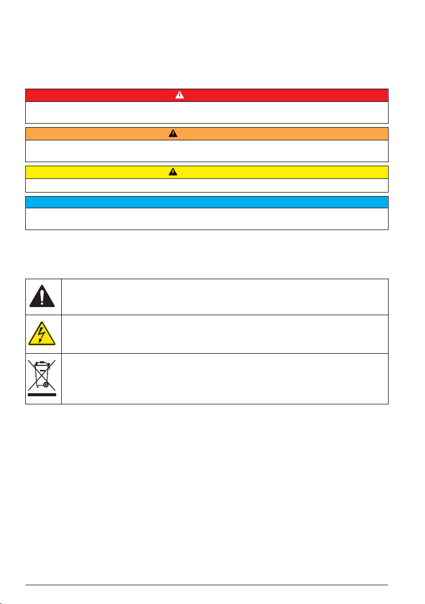
This symbol, if noted on the instrument, references the instruction manual for operation and/or safety
information.
This symbol indicates that a risk of electrical shock and/or electrocution exists.
Electrical equipment marked with this symbol may not be disposed of in European domestic or public
disposal systems. Return old or end-of-life equipment to the manufacturer for disposal at no charge to
the user.
Certification
Canadian Radio Interference-Causing Equipment Regulation, IECS-003, Class A:
Supporting test records reside with the manufacturer.
This Class A digital apparatus meets all requirements of the Canadian Interference-Causing
Equipment Regulations.
Cet appareil numérique de classe A répond à toutes les exigences de la réglementation canadienne
sur les équipements provoquant des interférences.
FCC Part 15, Class "A" Limits
Supporting test records reside with the manufacturer. The device complies with Part 15 of the FCC
Rules. Operation is subject to the following conditions:
1. The equipment may not cause harmful interference.
2. The equipment must accept any interference received, including interference that may cause
undesired operation.
Changes or modifications to this equipment not expressly approved by the party responsible for
compliance could void the user's authority to operate the equipment. This equipment has been tested
and found to comply with the limits for a Class A digital device, pursuant to Part 15 of the FCC rules.
These limits are designed to provide reasonable protection against harmful interference when the
4
English
Page 5
equipment is operated in a commercial environment. This equipment generates, uses and can
radiate radio frequency energy and, if not installed and used in accordance with the instruction
manual, may cause harmful interference to radio communications. Operation of this equipment in a
residential area is likely to cause harmful interference, in which case the user will be required to
correct the interference at their expense. The following techniques can be used to reduce
interference problems:
1. Disconnect the equipment from its power source to verify that it is or is not the source of the
interference.
2. If the equipment is connected to the same outlet as the device experiencing interference, connect
the equipment to a different outlet.
3. Move the equipment away from the device receiving the interference.
4. Reposition the receiving antenna for the device receiving the interference.
5. Try combinations of the above.
Product overview
N O T IC E
The use of a Real-Time Controller (RTC) module does not replace system maintenance. Make sure that all
instruments connected to the RTC controller are always in good condition. Regular maintenance is necessary to
make sure that the instruments supply correct, reliable measurement values. Refer to the user documentation of
each instrument.
RTC modules are general application control units that make some processes better in treatment
plants. RTC modules are available as 1-channel, 2-channel or multi-channel systems.
Multi-channel RTC modules are usually operated on industrial PCs (IPC) and all input/output signals
are transferred through the sc1000 controller. Refer to the sc1000 documentation. Refer to the
documentation supplied with the hardware.
Product components
N O T IC E
The combination of pre-assembled components supplied by the manufacturer does not show an independentlyfunctioning unit. In accordance with EU guidelines, this combination of pre-assembled components is not supplied
with a CE mark, and there is no EU declaration of conformity for the combination. However, the conformity of the
combination of components with the guidelines can be proved through technical measurements.
Make sure that all components have been received. If any items are missing or damaged, contact the
manufacturer or a sales representative immediately.
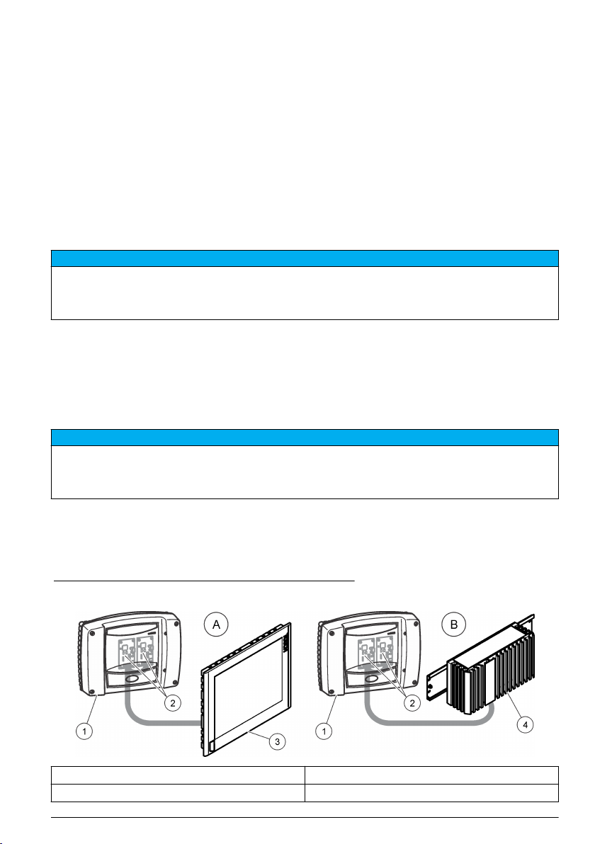
Figure 1 shows the sc1000 controller with an industrial PC. Version A shows the sc1000 installation
with a touch panel PC and version B with a DIN rail box PC.
Figure 1 Installation examples version A and version B
1 sc1000 controller 3 Touch panel PC
2 RTC communication card (2x) 4 DIN rail box PC
English 5
Page 6
Installation
W A R NI N G
Potential Electrocution Hazard. Only qualified personnel should conduct the tasks described in this
section of the manual.
C A U TI O N
Possible danger to sensor or logger. Always disconnect power to the instrument when making any
electrical connections.
Install the RTC module
Only install RTC DIN rail versions on a DIN rail. Only install an IPC panel mount versions according
to the IPC manufacturer specifications that are supplied with the hardware.
Attach the module horizontally. Make sure that the passive aeration element operates correctly.
Make sure that there is a minimum of 30 mm (1.2 in.) of space around the module.
To use the RTC module indoors, install the module in a control cabinet. To use the RTC module
outdoors, install the module in an enclosure. Refer to Specifications on page 3 for the enclosure
specifications.
An sc1000 controller is necessary to operate the RTC module. Refer to the sc1000 controller
documentation. It is necessary to use software version V2.30 (or higher) for the sc1000 controller.
Hardware is subject to change without notice. Refer to the sc1000 documentation and other
hardware documentation for input/output electrical wiring. Additional information of RTC controllers
and setting parameters is available on the manufacturer's website.
This instrument is rated for an altitude of 2000 m (6562 ft) maximum. Use of this instrument at an
altitude higher than 2000 m can slightly increase the potential for the electrical insulation to break
down, which can result in an electric shock hazard. The manufacturer recommends that users with
concerns contact technical support.
Supply power to the RTC module
D A N GE R
Electrocution hazard. Do not connect AC power directly to a DC powered instrument.
An external deactivation switch is necessary for all installations. Refer to Table 1.
Table 1 Supply voltage of the RTC module
Specification Description
Voltage 24 V DC (-15%/+20%), 120 W (maximum)
Recommended fuse C2
With 110–240 V option 240 V, 50–60 Hz, 120 VA (maximum)
Connect to the process instruments
The measurement signals of the sc sensors, analyzer and other input signals are supplied to the
RTC module through the RTC communication card in the sc1000. For information about the power
supply of the sc1000 controller and the sc sensors, refer to the applicable documentation for the
sc1000 controller and sc sensors.
6
English
Page 7
Connect to the controller
Attach the supplied SUB-D connector to a two-wire, shielded data cable (signal or bus cable). Refer
to the applicable documentation for the data cable connection.
Connect to external devices (optional)
N O T IC E
Network and access point security is the responsibility of the customer that uses the wireless instrument. The
manufacturer will not be liable for any damages, inclusive however not limited to indirect, special, consequential
or incidental damages, that have been caused by a gap in, or breach of network security.
Startup
User interface and navigation
Keypad description
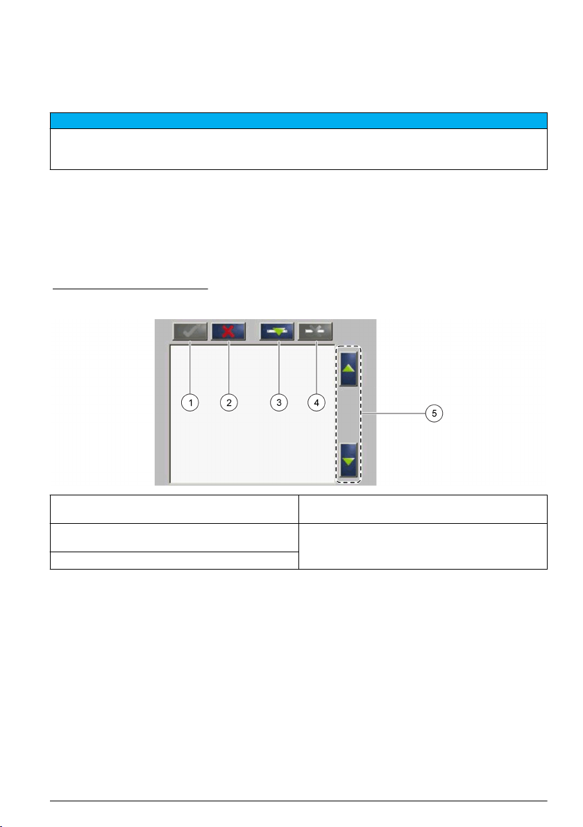
Refer to Figure 2 for the keypad description and navigation information.
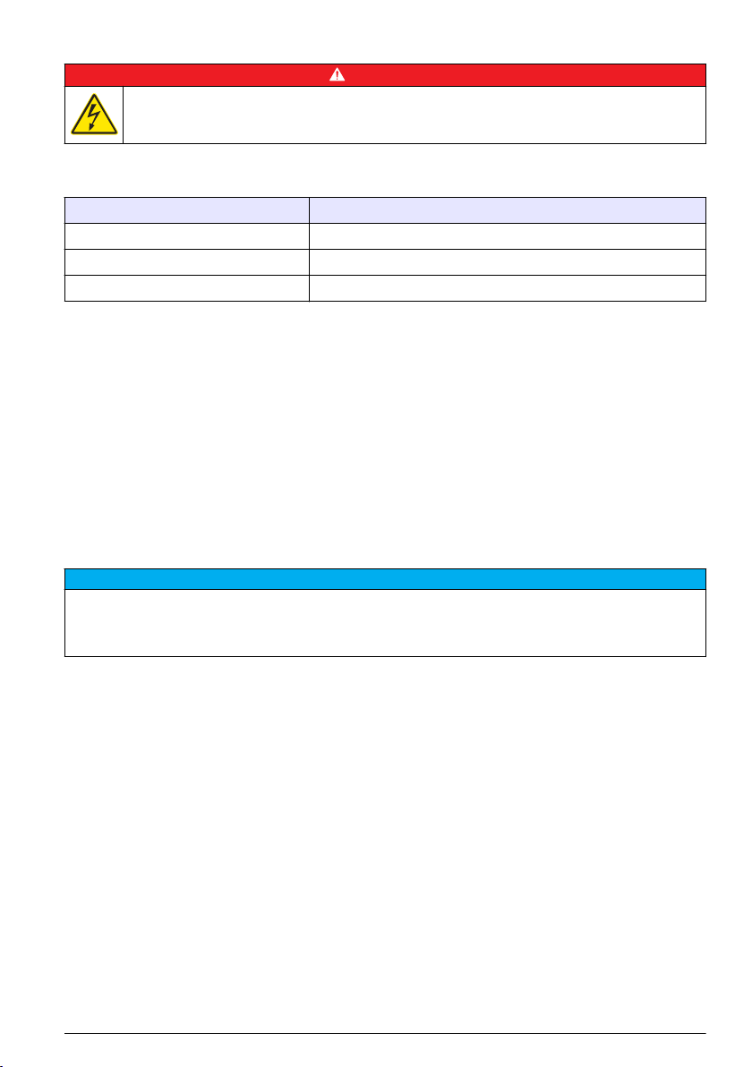
Figure 2 Keypad description
1 Enter: Saves the setting and exits the current
screen to the CONFIGURE menu
2 Cancel: Exits the current screen to the
CONFIGURE menu without saving the setting
3 Add: Adds a new sensor to the selection
4 Delete: Removes a sensor from the selection
5 UP and DOWN arrows: Moves the sensors up or
down the list
Add a sensor
Note: Make sure that an RTC communication card is installed in the sc1000 sensor module.
1. Connect the controller. Refer to the controller documentation.
2. Select MAIN MENU>RTC MODULES/PROGNOSYS>RTC
MODULES>RTC>CONFIGURE>SELECT SENSOR.
3. Push Add. Refer to Figure 3.
A list with all network connections shows.
4. Select the applicable sensor for the RTC module and push Enter. The sensor is shown in the
sensor list.
Note: The sensor names in black are available for an RTC module. The sensor names in red are not available
for an RTC module. A sensor name identified with a "(p)" is available for PROGNOSYS.
Note: The mA input cards and the PROFIBUS card (item no. YAB103) can supply RTC input signals.
5. Push Add to add more sensors or input cards from the list.
English
7
Page 8

Selected sensors show in gray. Refer to Figure 4 on page 8 to set the sensor sequence. Refer
to Figure 5 on page 9 to remove a sensor.
6. Push Enter to accept the list.
Figure 3 Add sensors
1 Select sensor 4 Add
2 Accept 5 Select additional sensor or input card
3 Sensor list
Sort the sensors (RTC modules only)
The sensor sequence is programmed in the RTC module for the measurement values. To sort the
sensors in the order specified for the RTC module, move the selected sensor with the UP and
DOWN arrows. Refer to Figure 4.
Figure 4 Sort the sensors
1 Select sensor 2 UP and DOWN arrows
Delete a sensor from the list
To delete a selected sensor from the list, push Delete. Refer to Figure 5.
8
English
Page 9
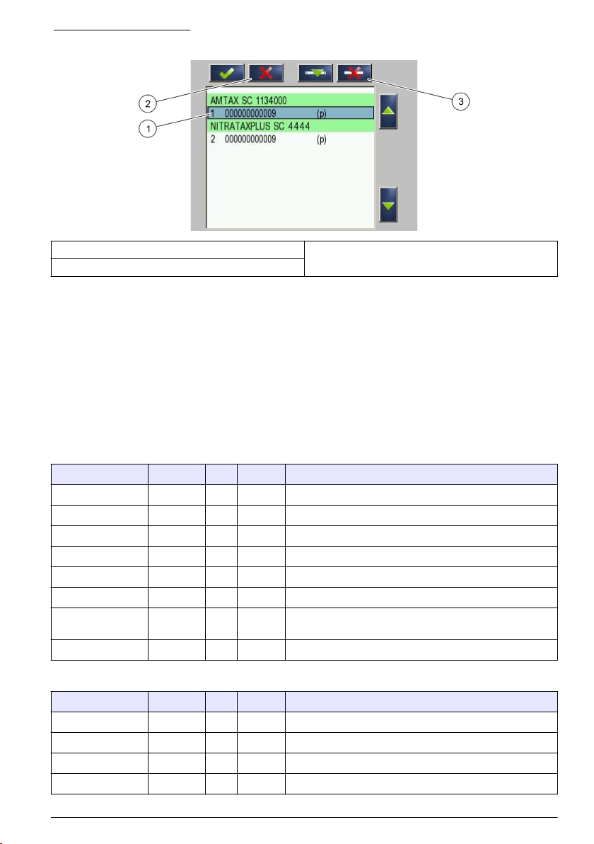
Figure 5 Delete a sensor
1 Select sensor 3 Delete the sensor
2 Go back without changes
RTC input and output variables values
All input and output signals are connected to the sc1000 controller or directly to the RTC module.
Refer to the RTC module and the sc1000 documentation.
Refer to Table 2 and Table 3 for the RTC101 P-module measurement values.
Refer to Table 4, Table 5, Table 6 and Table 7 for the RTC105 N/DN-module measurement values.
Refer to Table 8 and Table 9 for the RTC113 ST-module and RTC112 SD-module measurement
values.
Refer to Table 10 and Table 11 for the RTC103 N-module measurement values.
Refer to Table 12 for the RTC111 SRT-module measurement values.
Table 2 RTC101 P-module (1-channel)
Tag name Parameter Unit Channel Description
RTC input PO4-P mg/L 1 Phosphate
RTC input Flow rate L/s 1 Supply volume flow
MEASUREMENT 1 Q 1 L/s 1 Wastewater flow rate
ACTUAT VAR 2 Pdos 1 L/h 1 Set point precipitant dosing volume
ACTUAT VAR 3 Digi 1 — 1 Digital output for pulsed pump operation (ON/OFF)
ACTUAT VAR 4 Preg 1 L/h 1 Internal calculation variable for precipitant volume
ACTUAT VAR 5 ß' 1 — 1 Only with open loop: ß' otherwise internal calculation
ACTUAT VAR 6 Qras 1 L/s 1 Return sludge volume
variable.
Table 3 RTC101 P-module (2-channels)
Tag name Parameter Unit Channel Description
RTC input PO4-P mg/L 1 Phosphate 1
RTC input PO4-P mg/L 2 Phosphate 2
RTC input Flow rate L/s 1 Supply volume flow 1
RTC input Flow rate L/s 2 Supply volume flow 2
English 9
Page 10

Table 3 RTC101 P-module (2-channels) (continued)
Tag name Parameter Unit Channel Description
MEASUREMENT 1 Q 1 L/s 1 Wastewater flow rate channel 1
MEASUREMENT 2 Q 2 L/s 2 Wastewater flow rate channel 2
ACTUAT VAR 3 Pdos 1 L/h 1 Set point precipitant dosing volume
ACTUAT VAR 4 Digi 1 — 1 Digital output for pulsed pump operation (ON/OFF)
ACTUAT VAR 5 Preg 1 L/h 1 Internal calculation variable for precipitant volume
ACTUAT VAR 6 ß' 1 — 1 Only with open loop: ß' otherwise internal calculation
ACTUAT VAR 7 Qras 1 L/s 1 Return sludge volume
ACTUAT VAR 8 Pdos 2 L/h 2 Set point precipitant dosing volume
ACTUAT VAR 9 Digi 2 — 2 Digital output for pulsed pump operation (ON/OFF)
ACTUAT VAR 10 Preg 2 L/h 2 Internal calculation variable for precipitant volume
ACTUAT VAR 11 ß' 2 — 2 Only with open loop: ß' otherwise internal calculation
ACTUAT VAR 12 Qras 2 L/s 2 Return sludge volume
variable.
variable.
Table 4 RTC105 N/DN-module (1-channel)
Tag name Parameter Unit Channel Description
RTC input NH4-N mg/L 1 Ammonia
RTC input NO3-N mg/L 1 Nitrate
RTC input Flow rate L/s 1 Optional: Flow rate to biological treatment
MEASUREMENT 1 Qin 1 % 1 Flow rate as fed to the RTC
ACTUAT VAR 2 B_S 1 Stage 1 Blower stage (ON/OFF)
ACTUAT VAR 3 Nreg 1 — 1 Internal calculation value Nitrogen based
Table 5 RTC105 N/DN-module (2-channels)
Tag name Parameter Unit Channel Description
RTC input NH4-N mg/L 1 Ammonia 1
RTC input NO3-N mg/L 1 Nitrate 1
RTC input NH4-N mg/L 2 Ammonia 2
RTC input NO3-N mg/L 2 Nitrate 2
RTC input Flow rate L/s 1 Optional: Flow rate to biological treatment 1
RTC input Flow rate L/s 2 Optional: Flow rate to biological treatment 2
MEASUREMENT 1 Qin 1 % both Flow rate as fed to the RTC
ACTUAT VAR 2 B_S 1 Stage 1 Blower stage (ON/OFF)
ACTUAT VAR 3 Nreg 1 — 1 Internal calculation value Nitrogen based
ACTUAT VAR 4 B_S 2 Stage 2 Blower stage (ON/OFF)
ACTUAT VAR 5 Nreg 2 — 2 Internal calculation value Nitrogen based
10 English
Page 11

Table 6 RTC105 N/DN-module (1-channel with DO option)
Tag name Parameter Unit Channel Description
RTC input NH4-N mg/L 1 Ammonia
RTC input NO3-N mg/L 1 Nitrate
RTC input DO mg/L 1 Oxygen
RTC input Flow rate L/s 1 Optional: Flow rate to biological treatment
MEASUREMENT 1 Qin 1 % 1 Flow rate as fed to the RTC
ACTUAT VAR 2 B_S 1 Stage 1 Aeration stage (ON/OFF)
ACTUAT VAR 3 Nreg 1 — 1 Internal calculation value Nitrogen based
ACTUAT VAR 4 Oreg 1 — 1 Internal calculation value oxygen based
ACTUAT VAR 5 A_S 1 % 1 Aeration intensity VFD 1
ACTUAT VAR 6 A_S 2 % 1 Aeration intensity VFD 2
ACTUAT VAR 12 Osetp 1 mg/L 1 O2 set point
Table 7 RTC105 N/DN-module (2-channels with DO option)
Tag name Parameter Unit Channel Description
RTC input NH4-N mg/L 1 Ammonia 1
RTC input NO3-N mg/L 1 Nitrate 1
RTC input DO mg/L 1 Oxygen 1
RTC input NH4-N mg/L 2 Ammonia 2
RTC input NO3-N mg/L 2 Nitrate 2
RTC input DO mg/L 2 Oxygen 2
RTC input Flow rate L/s 1 Optional: Flow rate to biological treatment 1
RTC input Flow rate L/s 2 Optional: Flow rate to biological treatment 2
MEASUREMENT 1 Qin 1 % 1 Flow rate as fed to the RTC
ACTUAT VAR 2 B_S 1 Stage 1 Aeration stage (ON/OFF)
ACTUAT VAR 3 Nreg 1 — 1 Internal calculation value Nitrogen based
ACTUAT VAR 4 Oreg 1 — 1 Internal calculation value oxygen based
ACTUAT VAR 5 A_S 1 % 1 Aeration intensity VFD 1
ACTUAT VAR 6 A_S 2 % 1 Aeration intensity VFD 2
ACTUAT VAR 7 B_S 2 Stage 2 Aeration stage (ON/OFF) B_S 2
ACTUAT VAR 8 Nreg 2 — 2 Internal calculation value Nreg
ACTUAT VAR 9 Oreg 2 — 2 Internal calculation value Oreg
ACTUAT VAR 10 A_S 1 % 2 Aeration intensity VFD 1
ACTUAT VAR 11 A_S 2 % 2 Aeration intensity VFD 2
ACTUAT VAR 12 Osetp 1 mg/L 1 O2 set point
ACTUAT VAR 13 Osetp 2 mg/L 2 O2 set point
English 11
Page 12

Table 8 RTC113 ST-module and RTC112 SD-module (1-channel)
Tag name Parameter Unit Channel Description
RTC input TSSin 1 g/L 1 TS concentration in inflow
RTC input TSSeff 1 g/L 1 TS concentration in effluent
RTC input Feedflow 1 L/s 1 Actual feed flow rate
RTC input Polyflow 1 L/h 1 Actual polymer flow rate
RTC input Hopper 1 — 1 Pump (ON/OFF)
MEASUREMENT 1 Qin 1 L/s 1 Actual flow rate to thickening
MEASUREMENT 2 Qavg 1 L/s 1 Averaged flow rate to thickening (as defined in menu)
MEASUREMENT 3 Qdos 1 L/h 1 Quantity of polymer added
MEASUREMENT 4 Tsin 1 g/L 1 TS concentration in inflow (modified by averaging).
MEASUREMENT 5 Tsef 1 g/L 1 TS concentration in effluent (modified by averaging and
ACTUAT VAR 6 Pdos 1 L/h 1 Calculated set point for polymer flow
ACTUAT VAR 7 Fac 1 g/kg 1 Calculated polymer quantity (g/kg)
ACTUAT VAR 8 Feed 1 L/s 1 Calculated feed flow rate
hopper pump operation).
Table 9 RTC113 ST-module and RTC112 SD-module (2-channels)
Tag name Parameter Unit Channel Description
RTC input TSSin 1 g/L 1 TS concentration in inflow
RTC input TSSeff 1 g/L 1 TS concentration in effluent
RTC input Feedflow 1 L/s 1 Actual feed flow rate
RTC input Polyflow 1 L/h 1 Actual polymer flow rate
RTC input Hopper 1 — 1 Pump (ON/OFF)
RTC input TSSin 2 g/L 2 TS concentration in inflow
RTC input TSSeff 2 g/L 2 TS concentration in effluent
RTC input Feedflow 2 L/s 2 Actual feed flow rate
RTC input Polyflow 2 L/h 2 Actual polymer flow rate
RTC input Hopper 2 — 2 Pump (ON/OFF)
MEASUREMENT 1 Qin 1 L/s 2 Actual flow rate to thickening
MEASUREMENT 2 Qavg 1 L/s 1 Averaged flow rate to thickening (as defined in menu)
MEASUREMENT 3 Qdos 1 L/h 1 Quantity of polymer added
MEASUREMENT 4 Tsin 1 g/L 1 TS concentration in inflow (modified by averaging).
MEASUREMENT 5 Tsef 1 g/L 1 TS concentration in effluent (modified by averaging and
MEASUREMENT 6 Qin 2 L/s 2 Actual flow rate to thickening
MEASUREMENT 7 Qavg 2 L/s 2 Averaged flow rate to thickening
MEASUREMENT 8 Qdos 2 L/h 2 Quantity of polymer added
MEASUREMENT 9 Tsin 2 g/L 2 TS concentration in inflow (modified by averaging).
hopper pump operation).
12 English
Page 13

Table 9 RTC113 ST-module and RTC112 SD-module (2-channels) (continued)
Tag name Parameter Unit Channel Description
MEASUREMENT 10 Tsef 2 g/L 2 TS concentration in effluent (modified by averaging and
ACTUAT VAR 11 Pdos 1 L/h 1 Calculated set point for polymer flow
ACTUAT VAR 12 Fac 1 g/kg 1 Calculated polymer quantity (g/kg)
ACTUAT VAR 13 Feed 1 L/s 1 Calculated feed flow rate
ACTUAT VAR 14 Pdos 2 L/h 2 Calculated set point for polymer flow
ACTUAT VAR 15 Fac 2 g/kg 2 Calculated polymer quantity (g/kg)
ACTUAT VAR 16 Feed 2 L/s 2 Calculated feed flow rate
hopper pump operation).
Table 10 RTC103 N-module (1-channel)
Tag name Parameter Unit Channel Description
RTC input NH4-N_in 1 mg/L 1 NH4-N influent
RTC input NH4-N_eff 1 mg/L 1 NH4-N influent effluent
RTC input TSS 1 g/L 1 TS concentration
RTC input DO 1 mg/L 1 Oxygen concentration
RTC input Inflow 1 L/s 1 Flow rate aeration lane
RTC input IRC 1 L/s 1 Flow rate internal recirculation
RTC input RAS 1 L/s 1 Flow rate return sludge
MEASUREMENT 1 — % 1 Nitrifiers concentration
MEASUREMENT 2 SRT days 1 Sludge Retention Time
ACTUAT VAR 3 NH4-N kg/h 1 NH4-N influent load to nitrify.
ACTUAT VAR 4 NffO 1 mg/L 1 DO necessary calculated from influent load.
ACTUAT VAR 5 Osetp 1 mg/L 1 DO set point
ACTUAT VAR 6 Oreg 1 — 1 Internal calculation value oxygen based
ACTUAT VAR 7 B_S 1 Stage 1 Aeration stage
ACTUAT VAR 8 A_S 1 % 1 Aeration intensity VFD 1
ACTUAT VAR 9 A_S 2 % 1 Aeration intensity VFD 2
Table 11 RTC103 N-module (2-channels)
Tag name Parameter Unit Channel Description
RTC input NH4-N_in 1 mg/L 1 NH4-N influent
RTC input NH4-N_eff 1 mg/L 1 NH4-N influent effluent
RTC input TSS 1 g/L 1 TS concentration
RTC input DO 1 mg/L 1 Oxygen concentration
RTC input Inflow 1 L/s 1 Flow rate aeration lane
RTC input IRC 1 L/s 1 Flow rate internal recirculation
RTC input RAS 1 L/s 1 Flow rate return sludge
English 13
Page 14

Table 11 RTC103 N-module (2-channels) (continued)
Tag name Parameter Unit Channel Description
RTC input NH4-N_in 2 mg/L 2 NH4-N influent
RTC input NH4-N_eff 2 mg/L 2 NH4-N influent effluent
RTC input TSS 2 g/L 2 TS concentration
RTC input DO 2 mg/L 2 Oxygen concentration
RTC input Inflow 2 L/s 2 Flow rate aeration lane
RTC input IRC 2 L/s 2 Flow rate internal recirculation
RTC input RAS 2 L/s 2 Flow rate return sludge
MEASUREMENT 1 — % 1 Nitrifiers concentration
MEASUREMENT 2 SRT days 1 Sludge Retention Time
ACTUAT VAR 3 NH4-N kg/h 1 NH4-N influent load to nitrify.
ACTUAT VAR 4 NffO 1 mg/L 1 DO necessary calculation from influent load.
ACTUAT VAR 5 Osetp 1 mg/L 1 DO set point
ACTUAT VAR 6 Oreg 1 — 1 Internal calculation value oxygen based
ACTUAT VAR 7 B_S 1 Stage 1 Aeration stage
ACTUAT VAR 8 A_S 1 % 1 Aeration intensity VFD 1
ACTUAT VAR 9 A_S 2 % 1 Aeration intensity VFD 2
ACTUAT VAR 10 NH4-N kg/h 2 NH4-N influent load to nitrify.
ACTUAT VAR 11 NffO 2 mg/L 2 DO necessary calculated from influent load.
ACTUAT VAR 12 Osetp 2 mg/L 2 DO set point
ACTUAT VAR 13 Oreg 2 — 2 Internal calculation value oxygen based
ACTUAT VAR 14 B_S 2 Stage 2 Aeration stage
ACTUAT VAR 15 A_S 1 % 2 Aeration intensity VFD 1
ACTUAT VAR 16 A_S 2 % 2 Aeration intensity VFD 2
Table 12 RTC111 SRT-module (1-channel)
Tag name Parameter Unit Channel Description
RTC input TSS AE 1 g/L 1 TS concentration aeration basin
RTC input TSS SAS 1 g/L 1 TS concentration surplus activated sludge
RTC input TSS eff 1 g/L 1 TS concentration effluent
RTC input DO1_1 mg/L 1 O2 concentration aeration zone 1
RTC input DO1_2 mg/L 1 Optional: O2 concentration aeration zone 2
RTC input DO1_3 mg/L 1 Optional: O2 concentration aeration zone 3
RTC input DO1_4 mg/L 1 Optional: O2 concentration aeration zone 4
RTC input SAS flow 1 mg/L 1 Flow rate surplus activated sludge
RTC input Flow 1 mg/L 1 Flow rate influent
MEASUREMENT 1 Qeff 1 L/s 1 Effluent flow as supplied to the RTC.
14 English
Page 15

Table 12 RTC111 SRT-module (1-channel) (continued)
Tag name Parameter Unit Channel Description
MEASUREMENT 2 Qsas 1 L/s 1 Surplus activated sludge flow
MEASUREMENT 3 Qsasm 1 kg/h 1 Sludge mass flow in surplus start sludge
MEASUREMENT 4 Vol 1 m
MEASUREMENT 5 Vols 1 m
MEASUREMENT 6 TSmL 1 g/L 1 Averaged TS concentration in aeration basins during
MEASUREMENT 7 TSs s1 kg 1 Mass of sludge in aeration basins, averaged for past
MEASUREMENT 8 SRT 1 days 1 Calculated actual aerobic sludge retention time
ACTUAT VAR 9 SRTSP 1 days 1 Set point for aerobic sludge retention time
ACTUAT VAR 10 Qs c1 L/s 1 Theoretical flow set point for surplus start sludge flow
ACTUAT VAR 11 Qs 1 L/s 1 Effective set point for surplus activated sludge flow
ACTUAT VAR 12 Digi 1 no unit 1 Surplus activated sludge pump ON/OFF signal
ACTUAT VAR 13 msaSP 1 kg/d 1 Set point for sludge mass draws off.
ACTUAT VAR 14 msasd 1 kg/d 1 Surplus activated sludge mass draw off during last
ACTUAT VAR 15 msash 1 kg/h 1 Actual surplus activated sludge mass draw off.
ACTUAT VAR 16 msas 1 kg 1 Surplus activated sludge mass draw off during actual
3
1 Actually aerated volume
3
1 Averaged aerated volume during past sludge retention
time.
past sludge retention time.
sludge retention time.
including all preset limits.
24 hours.
calendar day.
Table 13 RTC111 SRT-module (2-channels)
Tag name Parameter Unit Channel Description
RTC input TSS AE 1 g/L 1 TS concentration aeration basin
RTC input TSS SAS 1 g/L 1 TS concentration surplus activated sludge
RTC input TSS eff 1 g/L 1 TS concentration effluent
RTC input DO1_1 mg/L 1 O2 concentration aeration zone 1
RTC input DO1_2 mg/L 1 Optional: O2 concentration aeration zone 2
RTC input DO1_3 mg/L 1 Optional: O2 concentration aeration zone 3
RTC input DO1_4 mg/L 1 Optional: O2 concentration aeration zone 4
RTC input SAS flow 1 mg/L 1 Flow rate surplus activated sludge
RTC input Flow 1 mg/L 1 Flow rate influent
RTC input TSS AE 2 g/L 2 TS concentration aeration basin
RTC input TSS SAS 2 g/L 2 TS concentration surplus activated sludge
RTC input TSS eff 2 g/L 2 TS concentration effluent
RTC input DO2_1 mg/L 2 O2 concentration aeration zone 1
RTC input DO2_2 mg/L 2 Optional: O2 concentration aeration zone 2
English 15
Page 16

Table 13 RTC111 SRT-module (2-channels) (continued)
Tag name Parameter Unit Channel Description
RTC input DO2_3 mg/L 2 Optional: O2 concentration aeration zone 3
RTC input DO2_4 mg/L 2 Optional: O2 concentration aeration zone 4
RTC input SAS flow 2 mg/L 2 Flow rate surplus activated sludge
RTC input Flow 2 mg/L 2 Flow rate influent
MEASUREMENT 1 Qeff 1 L/s 1 Effluent flow as supplied to the RTC.
MEASUREMENT 2 Qsas 1 L/s 1 Surplus activated sludge flow
MEASUREMENT 3 SRT 1 days 1 Calculated actual aerobic sludge retention time
MEASUREMENT 4 Qeff 2 L/s 2 Effluent flow as supplied to the RTC.
MEASUREMENT 5 Qsas 2 L/s 2 Surplus activated sludge flow
MEASUREMENT 6 SRT 2 days 2 Calculated actual aerobic sludge retention time
ACTUAT VAR 7 SRTSP 1 days 1 Set point for aerobic sludge retention time
ACTUAT VAR 8 Qs 1 L/s 1 Effective set point for surplus activated sludge flow
ACTUAT VAR 9 Digi 1 no unit 1 Surplus activated sludge pump ON/OFF signal
ACTUAT VAR 10 msaSP 1 kg/d 1 Set point for sludge mass draws off.
ACTUAT VAR 11 msas 1 kg 1 Surplus activated sludge mass draw off during actual
ACTUAT VAR 12 SRTSP 2 days 2 Set point for aerobic sludge retention time
ACTUAT VAR 13 Qs 2 L/s 2 Effective set point for surplus activated sludge flow
ACTUAT VAR 14 Digi 2 no unit 2 Surplus activated sludge pump ON/OFF signal
ACTUAT VAR 15 msaSP 2 kg/d 2 Set point for sludge mass draws off.
ACTUAT VAR 16 msas 2 kg 2 Surplus activated sludge mass draw off during actual
including all preset limits.
calendar day.
including all preset limits.
calendar day.
Troubleshooting
Warnings
Warning Description Solution
MODBUS ADDRESS The RTC menu SET DEFAULTS
was selected. This deleted the
Modbus address of the RTC module
in the sc1000 controller.
PROBE SERVICE A configured sensor is in service
mode.
SENSOR MISSING A selected sensor was disconnected
from the sc1000 network.
SENSOR FAIL A selected sensor shows an error. Look at the error mode of selected sensors.
16 English
Access the following menu and set the correct
MODBUS address. Go to: MAIN MENU>RTC
MODULES/PROGNOSYS> RTC
MODULES>RTC> CONFIGURE>MODBUS>
ADDRESS.
Go to the TEST/MAINT menu of selected sensor
and end the SERVICE mode.
Connect the sensor to sc1000 network again.
Refer to the sensor documentation for
troubleshooting information.
Page 17

Warning Description Solution
SENSOR
EXCEPTION
CH1: FALLBACK
STRATEGY
CH2: FALLBACK
STRATEGY
ANALOGUE
INPUT1 FAULTY
ANALOGUE
INPUT2 FAULTY
ANALOGUE
INPUT3 FAULTY
ANALOGUE
INPUT4 FAULTY
LIMIT ACTIVE A user-defined parameter sets a
CHECK "SELECT
SENSOR"
A selected sensor supplied an
unknown signal to the
sc1000 network.
Channel 1 of the RTC module
started the substitutional strategy.
Channel 2 of the RTC module
started the substitutional strategy.
RTC analogue input signal is
defective.
limit for the RTC operation.
RTC module receives less
measurement values than
necessary. This warning likely
occurs with the SENSOR MISSING
warning.
Contact technical support.
Channel 1 of the RTC module started the
substitutional strategy (e.g., missing
measurement values).
Channel 2 of the RTC module started the
substitutional strategy (e.g., missing
measurement values).
Fix the analogue signal supply to RTC module.
If necessary, make sure that the limiting
parameters are correctly set. Make necessary
adjustments.
Make sure that all necessary instruments are
selected in the SELECT SENSOR menu.
Errors
Error Description Solution
RTC MISSING There is no communication
RTC CRC The communication between
CHECK CONFIG The sensor selection of the
TOO MANY PROBES Too many sensors selected in
TOO MANY
MEASUREMENTS
between RTC module and
RTC communication card.
RTC module and RTC
communication card was
cancelled.
RTC module was removed by
removal or selection of a new
sc1000 controller.
the SELECT SENSOR menu.
The probes selected in the
SELECT SENSOR have too
many measurements to be
operates by the RTC
communication card.
Supply RTC module with voltage.
Examine the connection cable.
Set the power of the sc1000 and the RTC module to
off. Wait until the system is completely voltage free. Set
the power of the sc1000 controller and the RTC module
to on.
Make sure that the +/- connections of the connector
cable between RTC and RTC communication card in
the sc1000 are installed correctly. Make the necessary
changes.
Go to: MAIN MENU>RTC
MODULES/PROGNOSYS>RTC MODULES>RTC>
CONFIGURE>SELECT SENSOR, select the correct
sensor for the RTC again and confirm.
Go to the SELECT SENSOR menu. Select no more
than 15 probes.
Go to the SELECT SENSOR menu. Select the number
of probes that have no more than 15 measurement
values.
English 17
Page 18
Error Description Solution
RTC FAILURE A general reading/writing error
SYNTAX ERROR
FORMULA TO LONG
ARGUMENT
LOGIC FUNCTION
BOUNDARY
FUNCTION
of on CF card, which was most
likely caused by a brief
interruption to the power
supply.
Error in PROGNOSYS *.binfile.
Acknowledge the error. If the message frequently
shows, remove the cause of power disruptions. If
necessary, contact technical support.
Use an updated version of PROGNOSYS that does not
show this error. Contact technical support.
Replacement parts and accessories
W A R NI N G
Personal injury hazard. Use of non-approved parts may cause personal injury, damage to the
instrument or equipment malfunction. The replacement parts in this section are approved by the
manufacturer.
Note: Product and Article numbers may vary for some selling regions. Contact the appropriate distributor or refer to
the company website for contact information.
Description Quantity Item no.
DIN rail NS 35/15 (DIN EN 60715 TH35), galvanized steel, 35 cm
(13.78 in.) length
Transformer, 90–240 V AC, 24 V DC, 0.75 A (for DIN rail NS 35/15) 1 LZH166
Terminal block for 24 V connection, without power supply 1 LZH167
Terminal block, grounding 1 LZH168
SUB-D connector 1 LZH169
Circuit breaker, C2 1 LZH170
RTC communication card 1 YAB117
CF card, basic type for all RTC multi-channel modules, 8 GB 1 LZY748-A0
1 LZH165
18 English
Page 19

Inhaltsverzeichnis
Technische Daten auf Seite 19 Werte der RTC-Eingangs- und -ausgangsvariablen
Allgemeine Informationen auf Seite 19 Fehlerbehebung auf Seite 34
Installation auf Seite 22 Ersatzteile und Zubehör auf Seite 36
Inbetriebnahme auf Seite 23
auf Seite 26
Zusätzliche Informationen
Zusätzliche Informationen finden Sie auf der Website des Herstellers.
Technische Daten
Änderungen vorbehalten.
Technische Daten Details
Verschmutzungsgrad 3
Schutzklasse III
Einbaukategorie I
Schutzgrad IP20
Befestigung DIN-Schiene EN 50022 oder Tafelmontage
Betriebstemperatur 0 bis 50 °C
Lagerungstemperatur –25 bis +85 °C (–13 bis +185 °F)
Relative Luftfeuchtigkeit 95 %, nicht kondensierend
Flash-Speicher CF Compact-Flash-Karte
Schnittstelle RJ 45 (Ethernet), 10/100 Mbit/s
Betriebssystem Microsoft Windows® CE oder Embedded Standard
Netzteil 24 V DC oder 100-240 V AC über externe Stromversorgung
Garantie 1 Jahr (EU: 2 Jahre)
Allgemeine Informationen
Der Hersteller ist nicht verantwortlich für direkte, indirekte, versehentliche oder Folgeschäden, die
aus Fehlern oder Unterlassungen in diesem Handbuch entstanden. Der Hersteller behält sich
jederzeit und ohne vorherige Ankündigung oder Verpflichtung das Recht auf Verbesserungen an
diesem Handbuch und den hierin beschriebenen Produkten vor. Überarbeitete Ausgaben der
Bedienungsanleitung sind auf der Hersteller-Webseite erhältlich.
Sicherheitshinweise
H I N WE IS
Der Hersteller ist nicht für Schäden verantwortlich, die durch Fehlanwendung oder Missbrauch dieses Produkts
entstehen, einschließlich, aber ohne Beschränkung auf direkte, zufällige oder Folgeschäden, und lehnt jegliche
Haftung im gesetzlich zulässigen Umfang ab. Der Benutzer ist selbst dafür verantwortlich, schwerwiegende
Anwendungsrisiken zu erkennen und erforderliche Maßnahmen durchzuführen, um die Prozesse im Fall von
möglichen Gerätefehlern zu schützen.
Deutsch 19
Page 20
Bitte lesen Sie dieses Handbuch komplett durch, bevor Sie dieses Gerät auspacken, aufstellen oder
bedienen. Beachten Sie alle Gefahren- und Warnhinweise. Nichtbeachtung kann zu schweren
Verletzungen des Bedieners oder Schäden am Gerät führen.
Stellen Sie sicher, dass die durch dieses Messgerät bereitgestellte Sicherheit nicht beeinträchtigt
wird. Verwenden bzw. installieren Sie das Messsystem nur wie in diesem Handbuch beschrieben.
Bedeutung von Gefahrenhinweisen
G E F AH R
Kennzeichnet eine mögliche oder drohende Gefahrensituation, die, wenn sie nicht vermieden wird, zum Tod oder
zu schweren Verletzungen führt.
Kennzeichnet eine mögliche oder drohende Gefahrensituation, die, wenn sie nicht vermieden wird, zum Tod oder
zu schweren Verletzungen führen kann.
Kennzeichnet eine mögliche Gefahrensituation, die zu geringeren oder moderaten Verletzungen führen kann.
Kennzeichnet eine Situation, die, wenn sie nicht vermieden wird, das Gerät beschädigen kann. Informationen, die
besonders beachtet werden müssen.
W A R NU N G
V O R SI C H T
H I N WE IS
Warnhinweise
Lesen Sie alle am Gerät angebrachten Aufkleber und Hinweise. Nichtbeachtung kann Verletzungen
oder Beschädigungen des Geräts zur Folge haben. Im Handbuch wird in Form von Warnhinweisen
auf die am Gerät angebrachten Symbole verwiesen.
Dieses Symbol am Gerät weist auf Betriebs- und/oder Sicherheitsinformationen im Handbuch hin.
Dieses Symbol weist auf die Gefahr eines elektrischen Schlages hin, der tödlich sein kann.
Elektrogeräte, die mit diesem Symbol gekennzeichnet sind, dürfen nicht im normalen öffentlichen
Abfallsystem entsorgt werden. Senden Sie Altgeräte an den Hersteller zurück. Dieser entsorgt die
Geräte ohne Kosten für den Benutzer.
Zertifizierung
Kanadische Vorschriften zu Störungen verursachenden Einrichtungen, IECS-003, Klasse A:
Entsprechende Prüfprotokolle hält der Hersteller bereit.
Dieses digitale Gerät der Klasse A erfüllt alle Vorgaben der kanadischen Normen für Interferenz
verursachende Geräte.
Cet appareil numérique de classe A répond à toutes les exigences de la réglementation canadienne
sur les équipements provoquant des interférences.
FCC Teil 15, Beschränkungen der Klasse "A"
Entsprechende Prüfprotokolle hält der Hersteller bereit. Das Gerät entspricht Teil 15 der FCCVorschriften. Der Betrieb unterliegt den folgenden Bedingungen:
1. Das Gerät darf keine Störungen verursachen.
2. Das Gerät muss jegliche Störung, die es erhält, einschließlich jener Störungen, die zu
unerwünschtem Betrieb führen, annehmen.
20
Deutsch
Page 21

Änderungen oder Modifizierungen an diesem Gerät, die nicht ausdrücklich durch die für die
Einhaltung der Standards verantwortliche Stelle bestätigt wurden, können zur Aufhebung der
Nutzungsberechtigung für dieses Gerät führen. Dieses Gerät wurde geprüft, und es wurde
festgestellt, dass es die Grenzwerte für digitale Geräte der Klasse A entsprechend Teil 15 der FCCVorschriften einhält. Diese Grenzwerte sollen einen angemessenen Schutz gegen
gesundheitsschädliche Störungen gewährleisten, wenn dieses Gerät in einer gewerblichen
Umgebung betrieben wird. Dieses Gerät erzeugt und nutzt hochfrequente Energie und kann diese
auch abstrahlen, und es kann, wenn es nicht in Übereinstimmung mit der Bedienungsanleitung
installiert und eingesetzt wird, schädliche Störungen der Funkkommunikation verursachen. Der
Betrieb dieses Geräts in Wohngebieten kann schädliche Störungen verursachen. In diesem Fall
muss der Benutzer die Störungen auf eigene Kosten beseitigen. Probleme mit Interferenzen lassen
sich durch folgende Methoden mindern:
1. Trennen Sie das Gerät von der Stromversorgung, um sicherzugehen, dass dieser die Störungen
nicht selbst verursacht.
2. Wenn das Gerät an die gleiche Steckdose angeschlossen ist wie das gestörte Gerät, schließen
Sie das störende Gerät an eine andere Steckdose an.
3. Vergrößern Sie den Abstand zwischen diesem Gerät und dem gestörten Gerät.
4. Ändern Sie die Position der Empfangsantenne des gestörten Geräts.
5. Versuchen Sie auch, die beschriebenen Maßnahmen miteinander zu kombinieren.
Produktübersicht
H I N WE IS
Die Nutzung eines RTC-Moduls ersetzt nicht die regelmäßige Wartung. Insbesondere ist sicherzustellen, dass
alle Geräte, die mit dem RTC-Controller verbunden sind, stets in einwandfreiem Zustand sind. Um
sicherzustellen, dass diese Geräte zuverlässig korrekte Messwerte liefern, sind regelmäßige Wartungsarbeiten
unerlässlich. Siehe Betriebsanleitung des entsprechenden Geräts.
RTC-Module sind universell einsetzbare Einheiten zur Anwendungssteuerung, mit denen sich
bestimmte Prozesse in Aufbereitungsanlagen verbessern lassen. RTC-Module sind als 1-Kanal-, 2Kanal- und Mehrkanal-Systeme erhältlich.
Mehrkanalige RTC-Module werden in der Regel auf industriellen PCs (IPC) betrieben, und die
Übertragung sämtlicher Eingangs- und Ausgangssignale erfolgt über den sc1000 Controller. Siehe
Dokumentation zum sc1000. Siehe die im Lieferumfang der Hardware enthaltene Dokumentation.
Produktkomponenten
H I N WE IS
Die vom Hersteller gelieferte Kombination von vormontierten Komponenten stellt für sich alleine keine
funktionierende Einheit dar. Gemäß EU-Richtlinien wird diese Kombination von vormontierten Komponenten nicht
mit einer CE- Kennzeichnung geliefert, und es wird für die Kombination keine EU-Konformitätserklärung erstellt.
Die Richtlinienkonformität der Kombination von Komponenten ist jedoch messtechnisch nachweisbar.
Stellen Sie sicher, dass Sie alle Teile erhalten haben. Wenn Komponenten fehlen oder beschädigt
sind, kontaktieren Sie bitte den Hersteller oder Verkäufer.
Abbildung 1 zeigt den sc1000 Controller mit industriellem PC. Version A zeigt die Installation des
sc1000 mit einem Touchpanel-PC und Version B mit einem Box-PC mit DIN-Schiene
Deutsch
21
Page 22
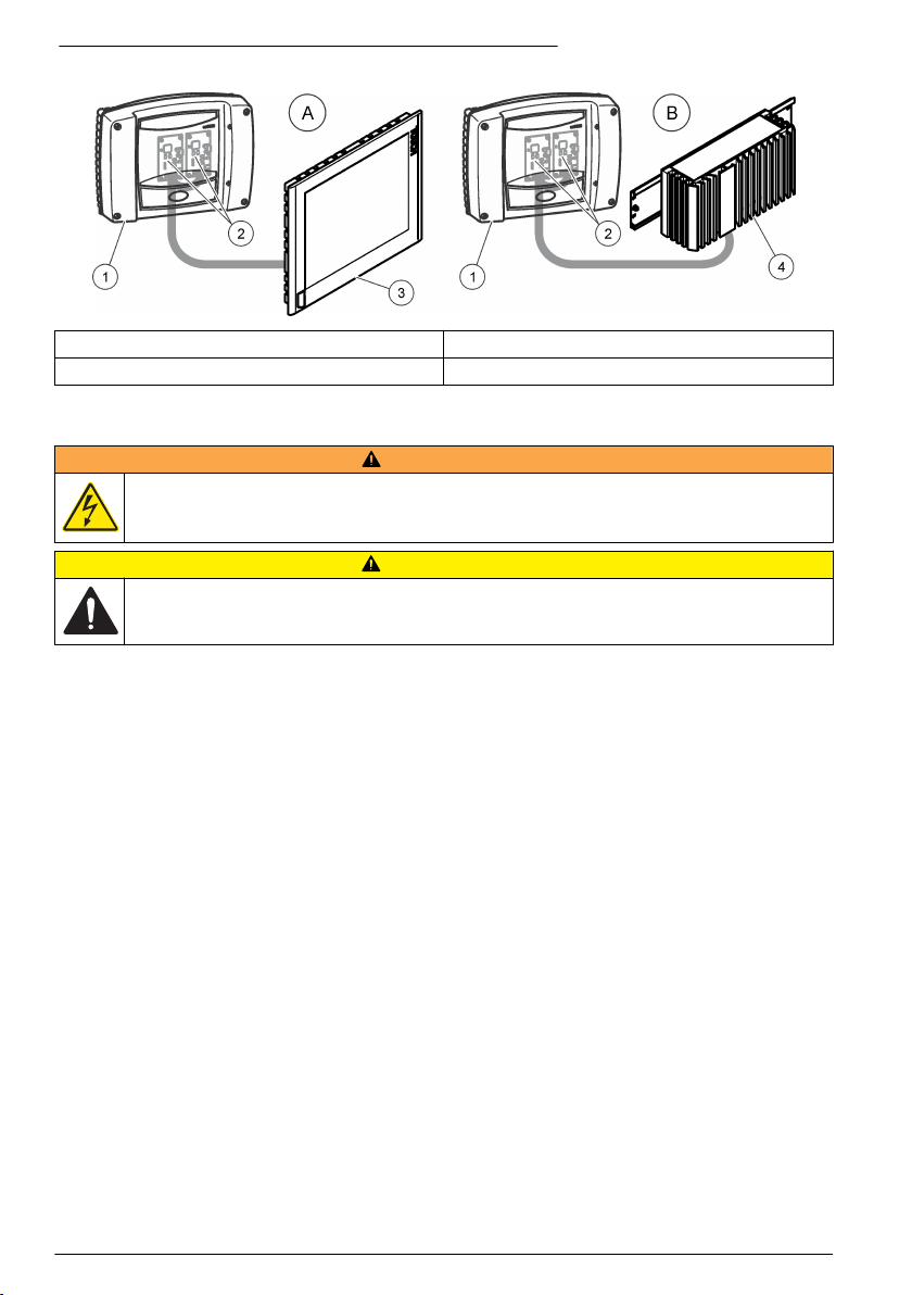
Abbildung 1 Installationsbeispiele Version A und Version B
1 sc1000 Controller 3 Touchpanel-PC
2 RTC-Kommunikationskarte (2x) 4 Box-PC mit DIN-Schiene
Installation
W A R NU N G
Potenzielle Stromschlaggefahr! Die in diesem Abschnitt des Handbuchs beschriebenen Eingriffe dürfen
ausschließlich von qualifiziertem Personal vorgenommen werden.
V O R SI C H T
Mögliche Gefahr für den Sensor oder Datensammler. Trennen Sie das Gerät stets vom Stromnetz,
bevor Sie elektrische Verbindungen herstellen oder trennen.
Installieren des RTC-Moduls
Installieren Sie auf einer DIN-Schiene nur RTC-Versionen, die für DIN-Schienen vorgesehen sind.
Montieren Sie IPC-Tafelmontageversionen gemäß den Spezifikationen des IPC-Herstellers, die im
Lieferumfang der Hardware enthalten sind.
Befestigen Sie das Modul waagerecht. Stellen Sie sicher, dass das passive Belüftungselement
ordnungsgemäß funktioniert. Es muss mindestens ein Abstand von 30 cm (1,2 in.) Abstand um das
Modul gegeben sein.
Im Innenbereich kann das RTC-Modul in einen Schaltschrank eingebaut werden. Im Außenbereich
benötigt das RTC-Modul ein geeignetes Gehäuse. Gehäuse-Spezifikationen finden Sie unter
Technische Daten auf Seite 19.
Das RTC-Modul wird nur über den sc1000 Controller bedient. Siehe Betriebsanleitung für den
sc1000 Controller. Die Softwareversion des sc1000 Controllers muss V3.20 oder höher sein.
Hardware kann ohne vorherige Ankündigung geändert werden. Anweisungen zur elektrischen
Verdrahtung der Ein- und Ausgänge finden Sie in der Dokumentation zum sc1000 Controller und
anderer Hardware. Weitere Informationen über RTC-Controller und Parametrierung sind auf der
Website des Herstellers verfügbar.
Dieses Gerät ist für eine Höhe von maximal 2000 m ausgelegt. Die Verwendung des Geräts bei einer
Höhe von über 2000 m führt möglicherweise zum Versagen der elektrischen Isolierung, was einen
elektrischen Schlag herbeiführen kann. Benutzer sollten bei Bedenken den technischen Support
kontaktieren.
22
Deutsch
Page 23
Versorgungsspannung zum RTC-Modul
G E F AH R
Lebensgefahr durch Stromschlag. Schließen Sie keine mit Gleichstrom betriebenen Geräte an
Wechselstrom an.
Für alle Installationen ist ein externer Deaktivierungsschalter erforderlich. Siehe Tabelle 1.
Tabelle 1 Versorgungsspannung des RTC-Moduls
Technische Daten Beschreibung
Spannung 24 V DC (-15 %/+20 %), 120 W (maximal)
Empfohlene Sicherung C2
Mit Option für 110–240 V 240 V, 50-60 Hz, 120 VA (maximal)
Anschluss an die Prozessinstrumente
Die Messsignale des sc-Sensors, Analysators und andere Eingangssignale werden über die RTCKommunikationskarte im sc1000 an das RTC-Modul übermittelt. Informationen über die
Stromversorgung für den sc1000-Controller und die sc-Sensoren finden Sie in der entsprechenden
Dokumentation für den sc1000-Controller und die sc-Sensoren.
Anschluss an den Controller
Schließen Sie den im Lieferumfang enthaltenen SUB-D-Anschluss an ein zweiadriges, geschirmtes
Datenkabel (Signal- oder Buskabel) an. Lesen Sie Informationen zum Anschluss des Datenkabels in
der zugehörigen Dokumentation nach.
Anschluss an externe Geräte (optional)
H I N WE IS
Die Sicherheit von Netzwerk und Zugangspunkt liegt in der Verantwortung des Kunden, der das drahtlose Gerät
verwendet. Der Hersteller ist nicht haftbar für Schäden, einschließlich aber nicht ausschließlich indirekte,
spezielle, zufällige oder Folgeschäden, die durch einen Eingriff oder eine Verletzung der Netzwerksicherheit
verursacht wurden.
Inbetriebnahme
Benutzerschnittstelle und Navigation
Beschreibung des Tastenfelds
Eine Beschreibung des Tastenfelds und Informationen zur Navigation finden Sie unterAbbildung 2.
Deutsch
23
Page 24
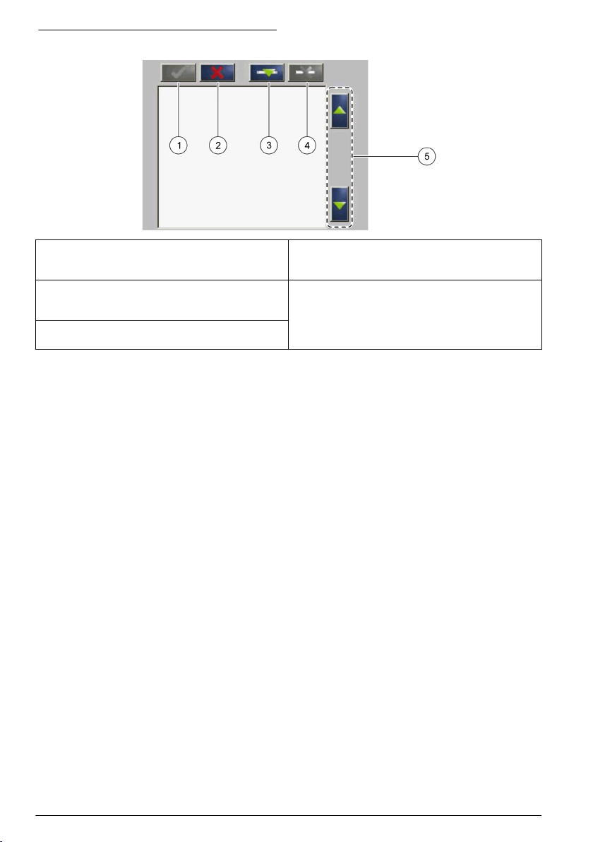
Abbildung 2 Beschreibung des Tastenfelds
1 Eingeben: Speichert die Einstellung und beendet
den aktuellen Bildschirm und kehrt in das Menü
CONFIGURE (Konfigurieren) zurück.
2 Abbrechen: Beendet den aktuellen Bildschirm und
kehrt zum Menü CONFIGURE (Konfigurieren)
zurück, ohne die Einstellung zu speichern.
3 Hinzufügen: Fügt der Auswahl einen neuen Sensor
hinzu
4 Löschen: Entfernt einen Sensor aus der Auswahl
5 AUFWÄRTS- und ABWÄRTS-Pfeiltasten:
Verschiebt die Sensoren in der Liste nach oben
oder unten.
Hinzufügen eines Sensors
Hinweis: Stellen Sie sicher, dass im sc1000-Sensormodul eine RTC-Kommunikationskarte installiert ist.
1. Schließen Sie den Controller an. Siehe die Controllerdokumentation.
2. Wählen Sie MAIN MENU>RTC MODULES/PROGNOSYS>RTC
MODULES>RTC>CONFIGURE>SELECT SENSOR (Hauptmenü>RTC-Module/Prognosys>RTCModule>RTC>Konfigurieren>Sensor auswählen) aus.
3. Drücken Sie Add (Hinzufügen). Siehe Abbildung 3.
Es wird eine Liste mit allen Netzwerkverbindungen angezeigt.
4. Wählen Sie den für das RTC-Modul geeigneten Sensor aus, und drücken Sie Enter
(Eingabetaste). Der Sensor wird in der Sensorliste angezeigt.
Hinweis: Die schwarzen Sensornamen sind für ein RTC-Modul verfügbar. Die roten Sensornamen sind nicht
für ein RTC-Modul verfügbar. Sensoren, deren Namen mit einem „(p)“ gekennzeichnet sind, sind für
PROGNOSYS verfügbar.
Hinweis: Die mA-Eingangskarten und die PROFIBUS-Karte (Bestellnr. YAB103) können RTC-Eingangssignale
übermitteln.
5. Drücken Sie Add (Hinzufügen), um weitere Sensoren oder Eingangskarten aus der Liste
hinzuzufügen.
Ausgewählte Sensoren werden in grau dargestellt. Zum Festlegen der Sensorreihenfolge siehe
Abbildung 4 auf Seite 25. Zum Entfernen eines Sensors siehe Abbildung 5 auf Seite 26.
6. Drücken Sie Enter (Eingabetaste), um die Liste zu akzeptieren.
24
Deutsch
Page 25
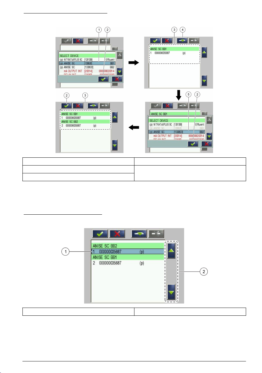
Abbildung 3 Sensoren hinzufügen
1 Sensor auswählen 4 Hinzufügen
2 Akzeptieren 5 Zusätzlichen Sensor oder Eingangskarte auswählen
3 Sensorliste
Sortieren der Sensoren (Nur RTC-Module)
Die Reihenfolge der Sensoren für die Messwerte ist im RTC-Modul programmiert. Um die Sensoren
in der für das RTC-Modul angegebenen Reihenfolge zu sortieren, verschieben Sie den
ausgewählten Sensor mit den AUFWÄRTS- und ABWÄRTS-Pfeiltasten. Siehe Abbildung 4.
Abbildung 4 Sensoren sortieren
1 Sensor auswählen 2 AUFWÄRTS- und ABWÄRTS-Pfeiltasten
Löschen eines Sensors aus der Liste
Drücken Sie Löschen, um einen ausgewählten Sensor aus der Liste zu löschen. Siehe Abbildung 5.
Deutsch
25
Page 26
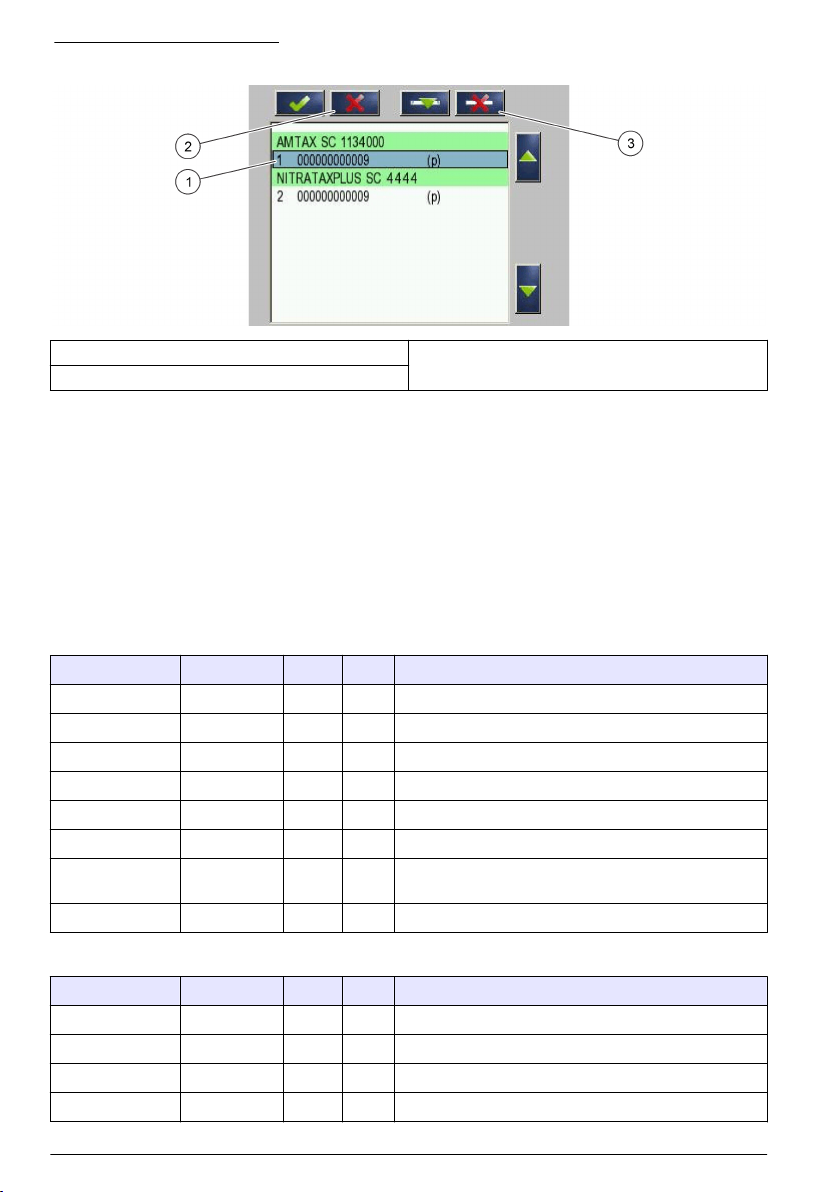
Abbildung 5 Sensor löschen
1 Sensor auswählen 3 Sensor löschen
2 Ohne Änderungen zurückgehen
Werte der RTC-Eingangs- und -ausgangsvariablen
Alle Eingangs- und Ausgangssignale sind mit dem sc1000 Controller oder direkt mit dem RTC-Modul
verbunden. Siehe die zum RTC-Modul und dem sc1000 Controller gehörige Dokumentation.
Siehe Tabelle 2 und Tabelle 3 für die Messwerte des RTC101 P-Moduls.
Siehe Tabelle 4, Tabelle 5, Tabelle 6 und Tabelle 7 für die Messwerte des RTC105 N/DN-Moduls.
Siehe Tabelle 8 und Tabelle 9 für die Messwerte des RTC113 ST-Moduls und des RTC112 SD-
Moduls.
Siehe Tabelle 10 und Tabelle 11 für die Messwerte des RTC103 N-Moduls.
Siehe Tabelle 12 für die Messwerte des RTC111 SRT-Moduls.
Tabelle 2 RTC101 P-Modul (1-Kanal)
Tag-Bezeichnung Parameter Einheit Kanal Beschreibung
RTC-Eingang PO4-P mg/l 1 Phosphat
RTC-Eingang Durchflussrate L/s 1 Zulauf Volumenstrom
MESSUNG 1 Q 1 L/s 1 Abwasser-Durchflussmenge
ACTUAT VAR 2 Pdos 1 l/h 1 Sollwert Fällmitteldosierung
ACTUAT VAR 3 Digi 1 — 1 Digitalausgang für Impulspumpenbetrieb (EIN/AUS)
ACTUAT VAR 4 Preg 1 l/h 1 Interne Berechnungsvariable für Fällmittelmenge
ACTUAT VAR 5 ß' 1 — 1 Nur im Modus Steuerung: ß' ansonsten interne
ACTUAT VAR 6 Qras 1 L/s 1 Rücklaufschlamm-Menge
Berechnungsvariable.
Tabelle 3 RTC101 P-Modul (2-Kanal)
Tag-Bezeichnung Parameter Einheit Kanal Beschreibung
RTC-Eingang PO4-P mg/l 1 Phosphat 1
RTC-Eingang PO4-P mg/l 2 Phosphat 2
RTC-Eingang Durchflussrate L/s 1 Zulauf Volumenstrom 1
RTC-Eingang Durchflussrate L/s 2 Zulauf Volumenstrom 2
26 Deutsch
Page 27
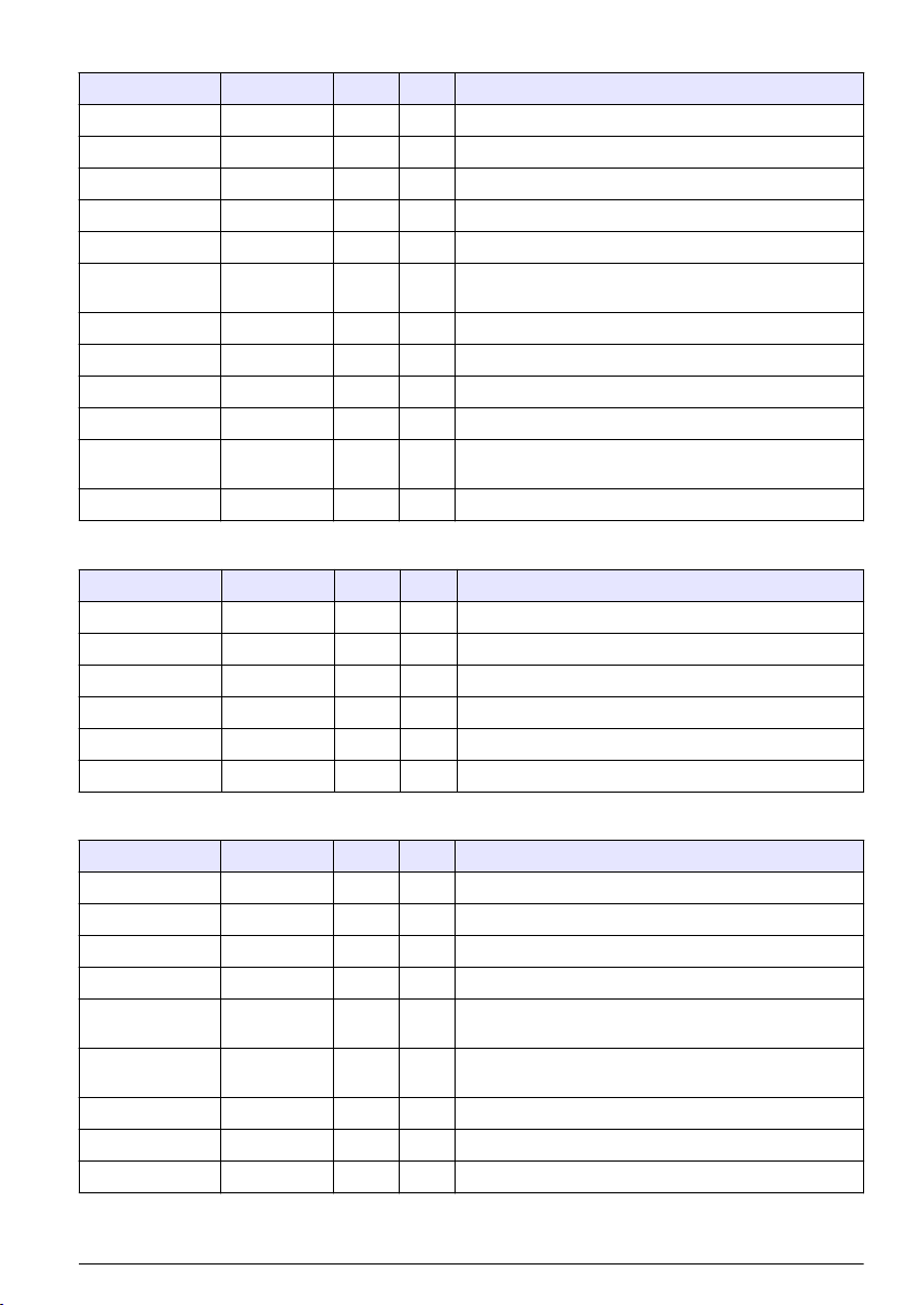
Tabelle 3 RTC101 P-Modul (2-Kanal) (fortgesetzt)
Tag-Bezeichnung Parameter Einheit Kanal Beschreibung
MESSUNG 1 Q 1 L/s 1 Abwasser-Durchflussmenge Kanal 1
MESSUNG 2 Q 2 L/s 2 Abwasser-Durchflussmenge Kanal 2
ACTUAT VAR 3 Pdos 1 l/h 1 Sollwert Fällmitteldosierung
ACTUAT VAR 4 Digi 1 — 1 Digitalausgang für Impulspumpenbetrieb (EIN/AUS)
ACTUAT VAR 5 Preg 1 l/h 1 Interne Berechnungsvariable für Fällmittelmenge
ACTUAT VAR 6 ß' 1 — 1 Nur im Modus Steuerung: ß' ansonsten interne
ACTUAT VAR 7 Qras 1 L/s 1 Rücklaufschlamm-Menge
ACTUAT VAR 8 Pdos 2 l/h 2 Sollwert Fällmitteldosierung
ACTUAT VAR 9 Digi 2 — 2 Digitalausgang für Impulspumpenbetrieb (EIN/AUS)
ACTUAT VAR 10 Preg 2 l/h 2 Interne Berechnungsvariable für Fällmittelmenge
ACTUAT VAR 11 ß' 2 — 2 Nur im Modus Steuerung: ß' ansonsten interne
ACTUAT VAR 12 Qras 2 L/s 2 Rücklaufschlamm-Menge
Berechnungsvariable.
Berechnungsvariable.
Tabelle 4 RTC105 N/DN-Modul (1-Kanal)
Tag-Bezeichnung Parameter Einheit Kanal Beschreibung
RTC-Eingang NH4-N mg/l 1 Ammoniak
RTC-Eingang NO3-N mg/l 1 Nitrat
RTC-Eingang Durchflussrate L/s 1 Optional: Durchflussmenge zur biologischen Aufbereitung
MESSUNG 1 Qin 1 % 1 Durchflussmenge
ACTUAT VAR 2 B_S 1 Stufe 1 Belüftungsstufe (EIN/AUS)
ACTUAT VAR 3 Nreg 1 — 1 Stickstoffbasierter interner Berechnungswert
Tabelle 5 RTC105 N/DN-Modul (2-Kanal)
Tag-Bezeichnung Parameter Einheit Kanal Beschreibung
RTC-Eingang NH4-N mg/l 1 Ammoniak 1
RTC-Eingang NO3-N mg/l 1 Nitrat 1
RTC-Eingang NH4-N mg/l 2 Ammoniak 2
RTC-Eingang NO3-N mg/l 2 Nitrat 2
RTC-Eingang Durchflussrate L/s 1 Optional: Durchflussmenge zur biologischen Aufbereitung
RTC-Eingang Durchflussrate L/s 2 Optional: Durchflussmenge zur biologischen Aufbereitung
MESSUNG 1 Qin 1 % beide Durchflussmenge
ACTUAT VAR 2 B_S 1 Stufe 1 Belüftungsstufe (EIN/AUS)
ACTUAT VAR 3 Nreg 1 — 1 Stickstoffbasierter interner Berechnungswert
1
2
Deutsch 27
Page 28

Tabelle 5 RTC105 N/DN-Modul (2-Kanal) (fortgesetzt)
Tag-Bezeichnung Parameter Einheit Kanal Beschreibung
ACTUAT VAR 4 B_S 2 Stufe 2 Belüftungsstufe (EIN/AUS)
ACTUAT VAR 5 Nreg 2 — 2 Stickstoffbasierter interner Berechnungswert
Tabelle 6 RTC105 N/DN-Modul (1-Kanal mit DO-Option)
Tag-Bezeichnung Parameter Einheit Kanal Beschreibung
RTC-Eingang NH4-N mg/l 1 Ammoniak
RTC-Eingang NO3-N mg/l 1 Nitrat
RTC-Eingang DO mg/l 1 Oxygen
RTC-Eingang Durchflussrate L/s 1 Optional: Durchflussmenge zur biologischen Aufbereitung
MESSUNG 1 Qin 1 % 1 Durchflussmenge
ACTUAT VAR 2 B_S 1 Stufe 1 Belüftungsstufe (EIN/AUS)
ACTUAT VAR 3 Nreg 1 — 1 Stickstoffbasierter interner Berechnungswert
ACTUAT VAR 4 Oreg 1 — 1 Sauerstoffbasierter interner Berechnungswert
ACTUAT VAR 5 A_S 1 % 1 Belüftungsintensität VFD 1
ACTUAT VAR 6 A_S 2 % 1 Belüftungsintensität VFD 2
ACTUAT VAR 12 Osetp 1 mg/l 1 O2-Sollwert
Tabelle 7 RTC105 N/DN-Modul (2-Kanal mit DO-Option)
Tag-Bezeichnung Parameter Einheit Kanal Beschreibung
RTC-Eingang NH4-N mg/l 1 Ammoniak 1
RTC-Eingang NO3-N mg/l 1 Nitrat 1
RTC-Eingang DO mg/l 1 Sauerstoff 1
RTC-Eingang NH4-N mg/l 2 Ammoniak 2
RTC-Eingang NO3-N mg/l 2 Nitrat 2
RTC-Eingang DO mg/l 2 Sauerstoff 2
RTC-Eingang Durchflussrate L/s 1 Optional: Durchflussmenge zur biologischen Aufbereitung
RTC-Eingang Durchflussrate L/s 2 Optional: Durchflussmenge zur biologischen Aufbereitung
MESSUNG 1 Qin 1 % 1 Durchflussmenge
ACTUAT VAR 2 B_S 1 Stufe 1 Belüftungsstufe (EIN/AUS)
ACTUAT VAR 3 Nreg 1 — 1 Stickstoffbasierter interner Berechnungswert
ACTUAT VAR 4 Oreg 1 — 1 Sauerstoffbasierter interner Berechnungswert
ACTUAT VAR 5 A_S 1 % 1 Belüftungsintensität VFD 1
ACTUAT VAR 6 A_S 2 % 1 Belüftungsintensität VFD 2
ACTUAT VAR 7 B_S 2 Stufe 2 Belüftungsstufe (EIN/AUS) B_S 2
ACTUAT VAR 8 Nreg 2 — 2 Interner Berechnungswert Nreg
1
2
28 Deutsch
Page 29

Tabelle 7 RTC105 N/DN-Modul (2-Kanal mit DO-Option) (fortgesetzt)
Tag-Bezeichnung Parameter Einheit Kanal Beschreibung
ACTUAT VAR 9 Oreg 2 — 2 Interner Berechnungswert Oreg
ACTUAT VAR 10 A_S 1 % 2 Belüftungsintensität VFD 1
ACTUAT VAR 11 A_S 2 % 2 Belüftungsintensität VFD 2
ACTUAT VAR 12 Osetp 1 mg/l 1 O2-Sollwert
ACTUAT VAR 13 Osetp 2 mg/l 2 O2-Sollwert
Tabelle 8 RTC113 ST-Modul und RTC112 SD-Modul (1-Kanal)
Tag-Bezeichnung Parameter Einheit Kanal Beschreibung
RTC-Eingang TSSin 1 g/l 1 TS-Konzentration im Zulauf
RTC-Eingang TSSeff 1 g/l 1 TS-Konzentration im Ablauf
RTC-Eingang Feedflow 1 L/s 1 Tatsächliche Beschickungsmenge
RTC-Eingang Polyflow 1 l/h 1 Tatsächliche Polymer-Flussrate
RTC-Eingang Hopper 1 — 1 Pumpe (EIN/AUS)
MESSUNG 1 Qin 1 L/s 1 Tatsächliche Durchflussmenge zur
MESSUNG 2 Qavg 1 L/s 1 Durchschnittliche Durchflussmenge zur
MESSUNG 3 Qdos 1 l/h 1 Menge hinzugefügtes Polymer
MESSUNG 4 Tsin 1 g/l 1 TS-Konzentration im Zulauf (modifiziert durch
MESSUNG 5 Tsef 1 g/l 1 TS-Konzentration im Ablauf (modifiziert durch
ACTUAT VAR 6 Pdos 1 l/h 1 Berechneter Sollwert für Polymer-Fluss
ACTUAT VAR 7 Fac 1 g/kg 1 Berechnete Polymer-Menge (g/kg)
ACTUAT VAR 8 Feed 1 L/s 1 Berechnete Beschickungsmenge
Eindickung/Entwässerung
Eindickung/Entwässerung (wie im Menü definiert)
Mittelwertbildung).
Mittelwertbildung und Betrieb der Trichterpumpe).
Tabelle 9 RTC113 ST-Modul und RTC112 SD-Modul (2-Kanal)
Tag-Bezeichnung Parameter Einheit Kanal Beschreibung
RTC-Eingang TSSin 1 g/l 1 TS-Konzentration im Zulauf
RTC-Eingang TSSeff 1 g/l 1 TS-Konzentration im Ablauf
RTC-Eingang Feedflow 1 L/s 1 Tatsächliche Beschickungsmenge
RTC-Eingang Polyflow 1 l/h 1 Tatsächliche Polymer-Flussrate
RTC-Eingang Hopper 1 — 1 Pumpe (EIN/AUS)
RTC-Eingang TSSin 2 g/l 2 TS-Konzentration im Zulauf
RTC-Eingang TSSeff 2 g/l 2 TS-Konzentration im Ablauf
RTC-Eingang Feedflow 2 L/s 2 Tatsächliche Beschickungsmenge
RTC-Eingang Polyflow 2 l/h 2 Tatsächliche Polymer-Flussrate
RTC-Eingang Hopper 2 — 2 Pumpe (EIN/AUS)
Deutsch 29
Page 30

Tabelle 9 RTC113 ST-Modul und RTC112 SD-Modul (2-Kanal) (fortgesetzt)
Tag-Bezeichnung Parameter Einheit Kanal Beschreibung
MESSUNG 1 Qin 1 L/s 2 Tatsächliche Durchflussmenge zur
MESSUNG 2 Qavg 1 L/s 1 Durchschnittliche Durchflussmenge zur
MESSUNG 3 Qdos 1 l/h 1 Menge hinzugefügtes Polymer
MESSUNG 4 Tsin 1 g/l 1 TS-Konzentration im Zulauf (modifiziert durch
MESSUNG 5 Tsef 1 g/l 1 TS-Konzentration im Ablauf (modifiziert durch
MESSUNG 6 Qin 2 L/s 2 Tatsächliche Durchflussmenge zur
MESSUNG 7 Qavg 2 L/s 2 Durchschnittliche Durchflussmenge bis zur
MESSUNG 8 Qdos 2 l/h 2 Menge hinzugefügtes Polymer
MESSUNG 9 Tsin 2 g/l 2 TS-Konzentration im Zulauf (modifiziert durch
MESSUNG 10 Tsef 2 g/l 2 TS-Konzentration im Ablauf (modifiziert durch
ACTUAT VAR 11 Pdos 1 l/h 1 Berechneter Sollwert für Polymer-Fluss
ACTUAT VAR 12 Fac 1 g/kg 1 Berechnete Polymer-Menge (g/kg)
ACTUAT VAR 13 Feed 1 L/s 1 Berechnete Beschickungsmenge
ACTUAT VAR 14 Pdos 2 l/h 2 Berechneter Sollwert für Polymer-Fluss
ACTUAT VAR 15 Fac 2 g/kg 2 Berechnete Polymer-Menge (g/kg)
ACTUAT VAR 16 Feed 2 L/s 2 Berechnete Beschickungsmenge
Eindickung/Entwässerung
Eindickung/Entwässerung (wie im Menü definiert)
Mittelwertbildung).
Mittelwertbildung und Betrieb der Trichterpumpe).
Eindickung/Entwässerung
Eindickung/Entwässerung
Mittelwertbildung).
Mittelwertbildung und Betrieb der Trichterpumpe).
Tabelle 10 RTC103 N-Modul (1-Kanal)
Tag-Bezeichnung Parameter Einheit Kanal Beschreibung
RTC-Eingang NH4-N_in 1 mg/l 1 NH4-N Zulauf
RTC-Eingang NH4-N_eff 1 mg/l 1 NH4-N Zulauf/Ablauf
RTC-Eingang TSS 1 g/l 1 TS-Konzentration
RTC-Eingang DO 1 mg/l 1 Sauerstoffkonzentration
RTC-Eingang Zulauf 1 L/s 1 Zulaufmenge Belebungsbecken
RTC-Eingang IRC 1 L/s 1 Durchflussmenge interne Rezirkulation
RTC-Eingang RAS 1 L/s 1 Durchflussmenge Rücklaufschlamm
MESSUNG 1 — % 1 Konzentration Nitrifikanten
MESSUNG 2 SRT Tage 1 Aerobes Schlammalter
ACTUAT VAR 3 NH4-N kg/h 1 Zu nitrifizierende NH4-N-Fracht im Zulauf.
ACTUAT VAR 4 NffO 1 mg/l 1 Aus Fracht im Zulauf berechneter O2-Bedarf.
ACTUAT VAR 5 Osetp 1 mg/l 1 O2-Sollwert
30 Deutsch
Page 31

Tabelle 10 RTC103 N-Modul (1-Kanal) (fortgesetzt)
Tag-Bezeichnung Parameter Einheit Kanal Beschreibung
ACTUAT VAR 6 Oreg 1 — 1 Sauerstoffbasierter interner Berechnungswert
ACTUAT VAR 7 B_S 1 Stufe 1 Belüftungsstufe
ACTUAT VAR 8 A_S 1 % 1 Belüftungsintensität VFD 1
ACTUAT VAR 9 A_S 2 % 1 Belüftungsintensität VFD 2
Tabelle 11 RTC103 N-Modul (2-Kanal)
Tag-Bezeichnung Parameter Einheit Kanal Beschreibung
RTC-Eingang NH4-N_in 1 mg/l 1 NH4-N Zulauf
RTC-Eingang NH4-N_eff 1 mg/l 1 NH4-N Zulauf/Ablauf
RTC-Eingang TSS 1 g/l 1 TS-Konzentration
RTC-Eingang DO 1 mg/l 1 Sauerstoffkonzentration
RTC-Eingang Zulauf 1 L/s 1 Zulaufmenge Belebungsbecken
RTC-Eingang IRC 1 L/s 1 Durchflussmenge interne Rezirkulation
RTC-Eingang RAS 1 L/s 1 Durchflussmenge Rücklaufschlamm
RTC-Eingang NH4-N_in 2 mg/l 2 NH4-N Zulauf
RTC-Eingang NH4-N_eff 2 mg/l 2 NH4-N Zulauf/Ablauf
RTC-Eingang TSS 2 g/l 2 TS-Konzentration
RTC-Eingang DO 2 mg/l 2 Sauerstoffkonzentration
RTC-Eingang Zulauf 2 L/s 2 Zulaufmenge Belebungsbecken
RTC-Eingang IRC 2 L/s 2 Durchflussmenge interne Rezirkulation
RTC-Eingang RAS 2 L/s 2 Durchflussmenge Rücklaufschlamm
MESSUNG 1 — % 1 Konzentration Nitrifikanten
MESSUNG 2 SRT Tage 1 Aerobes Schlammalter
ACTUAT VAR 3 NH4-N kg/h 1 Zu nitrifizierende NH4-N-Fracht im Zulauf.
ACTUAT VAR 4 NffO 1 mg/l 1 Aus Fracht im Zulauf berechneter DO-Bedarf
ACTUAT VAR 5 Osetp 1 mg/l 1 O2-Sollwert
ACTUAT VAR 6 Oreg 1 — 1 Sauerstoffbasierter interner Berechnungswert
ACTUAT VAR 7 B_S 1 Stufe 1 Belüftungsstufe
ACTUAT VAR 8 A_S 1 % 1 Belüftungsintensität VFD 1
ACTUAT VAR 9 A_S 2 % 1 Belüftungsintensität VFD 2
ACTUAT VAR 10 NH4-N kg/h 2 Zu nitrifizierende NH4-N-Fracht im Zulauf.
ACTUAT VAR 11 NffO 2 mg/l 2 Aus Fracht im Zulauf berechneter O2-Bedarf.
ACTUAT VAR 12 Osetp 2 mg/l 2 O2-Sollwert
ACTUAT VAR 13 Oreg 2 — 2 Sauerstoffbasierter interner Berechnungswert
ACTUAT VAR 14 B_S 2 Stufe 2 Belüftungsstufe
Deutsch 31
Page 32

Tabelle 11 RTC103 N-Modul (2-Kanal) (fortgesetzt)
Tag-Bezeichnung Parameter Einheit Kanal Beschreibung
ACTUAT VAR 15 A_S 1 % 2 Belüftungsintensität VFD 1
ACTUAT VAR 16 A_S 2 % 2 Belüftungsintensität VFD 2
Tabelle 12 RTC111 SRT-Modul (1-Kanal)
Tag-Bezeichnung Parameter Einheit Kanal Beschreibung
RTC-Eingang TSS AE 1 g/l 1 TS-Konzentration Belebungsbecken
RTC-Eingang TSS SAS 1 g/l 1 TS-Konzentration im Überschussschlamm
RTC-Eingang TSS eff 1 g/l 1 TS-Konzentration Ablauf Nachklärung
RTC-Eingang DO1_1 mg/l 1 O2-Konzentration Belüftungszone 1
RTC-Eingang DO1_2 mg/l 1 Optional: O2-Konzentration Belüftungszone 2
RTC-Eingang DO1_3 mg/l 1 Optional: O2-Konzentration Belüftungszone 3
RTC-Eingang DO1_4 mg/l 1 Optional: O2-Konzentration Belüftungszone 4
RTC-Eingang SAS flow 1 mg/l 1 Durchflussmenge Überschussschlamm
RTC-Eingang Flow 1 mg/l 1 Durchflussmenge Zulauf
MESSUNG 1 Qeff 1 L/s 1 Durchflussmenge im Ablauf.
MESSUNG 2 Qsas 1 L/s 1 Durchflussmenge Überschussschlamm
MESSUNG 3 Qsasm 1 kg/h 1 Schlammmassenfluss in überschüssigem aktiviertem
MESSUNG 4 Vol 1 m
MESSUNG 5 Vols 1 m
3
3
MESSUNG 6 TSmL 1 g/l 1 Mittelwert TS-Konzentration in Belebungsbecken
MESSUNG 7 TSs s1 kg 1 Schlammmasse in Belüftungsbecken, Mittelwert für
MESSUNG 8 SRT 1 Tage 1 Berechnetes tatsächliches aerobes Schlammalter
ACTUAT VAR 9 SRTSP 1 Tage 1 Sollwert für das aerobe Schlammalter
ACTUAT VAR 10 Qs c1 L/s 1 Theoretischer Fluss-Sollwert für überschüssigen
ACTUAT VAR 11 Qs 1 L/s 1 Effektiver Sollwert für den Überschussschlammfluss
ACTUAT VAR 12 Digi 1 keine Einheit 1 EIN/AUS-Signal für die
ACTUAT VAR 13 msaSP 1 kg/d 1 Sollwert für Abzug der Schlammmasse
ACTUAT VAR 14 msasd 1 kg/d 1 Abzug der Überschuss-Schlammmasse während der
ACTUAT VAR 15 msash 1 kg/h 1 Tatsächlicher Abzug der Überschuss-Schlammmasse.
ACTUAT VAR 16 msas 1 kg 1 Abzug der Überschluss-Schlammasse während des
Schlamm
1 Tatsächlich belüftetes Volumen
1 Mittelwert für belüftetes Volumen während des letzten
Schlammalters.
während des letzten Schlammalters.
letztes Schlammalter.
aktivierten Schlammfluss
einschließlich aller voreingestellten Grenzwerte.
Überschussschlammabzugspumpe
letzten 24 Stunden.
aktuellen Kalendertages.
32 Deutsch
Page 33

Tabelle 13 RTC111 SRT-Modul (2-Kanal)
Tag-Bezeichnung Parameter Einheit Kanal Beschreibung
RTC-Eingang TSS AE 1 g/l 1 TS-Konzentration Belebungsbecken
RTC-Eingang TSS SAS 1 g/l 1 TS-Konzentration im Überschussschlamm
RTC-Eingang TSS eff 1 g/l 1 TS-Konzentration Ablauf Nachklärung
RTC-Eingang DO1_1 mg/l 1 O2-Konzentration Belüftungszone 1
RTC-Eingang DO1_2 mg/l 1 Optional: O2-Konzentration Belüftungszone 2
RTC-Eingang DO1_3 mg/l 1 Optional: O2-Konzentration Belüftungszone 3
RTC-Eingang DO1_4 mg/l 1 Optional: O2-Konzentration Belüftungszone 4
RTC-Eingang SAS flow 1 mg/l 1 Durchflussmenge Überschussschlamm
RTC-Eingang Flow 1 mg/l 1 Durchflussmenge Zulauf
RTC-Eingang TSS AE 2 g/l 2 TS-Konzentration Belebungsbecken
RTC-Eingang TSS SAS 2 g/l 2 TS-Konzentration im Überschussschlamm
RTC-Eingang TSS eff 2 g/l 2 TS-Konzentration Ablauf Nachklärung
RTC-Eingang DO2_/1 mg/l 2 O2-Konzentration Belüftungszone 1
RTC-Eingang DO2_2 mg/l 2 Optional: O2-Konzentration Belüftungszone 2
RTC-Eingang DO2_3 mg/l 2 Optional: O2-Konzentration Belüftungszone 3
RTC-Eingang DO2_4 mg/l 2 Optional: O2-Konzentration Belüftungszone 4
RTC-Eingang SAS flow 2 mg/l 2 Durchflussmenge Überschussschlamm
RTC-Eingang Flow 2 mg/l 2 Durchflussmenge Zulauf
MESSUNG 1 Qeff 1 L/s 1 Durchflussmenge im Ablauf.
MESSUNG 2 Qsas 1 L/s 1 Durchflussmenge Überschussschlamm
MESSUNG 3 SRT 1 Tage 1 Berechnetes tatsächliches aerobes Schlammalter
MESSUNG 4 Qeff 2 L/s 2 Durchflussmenge im Ablauf.
MESSUNG 5 Qsas 2 L/s 2 Durchflussmenge Überschussschlamm
MESSUNG 6 SRT 2 Tage 2 Berechnetes tatsächliches aerobes Schlammalter
ACTUAT VAR 7 SRTSP 1 Tage 1 Sollwert für das aerobe Schlammalter
ACTUAT VAR 8 Qs 1 L/s 1 Effektiver Sollwert für den Überschussschlammfluss
ACTUAT VAR 9 Digi 1 keine Einheit 1 EIN/AUS-Signal für die
ACTUAT VAR 10 msaSP 1 kg/d 1 Sollwert für Abzug der Schlammmasse
ACTUAT VAR 11 msas 1 kg 1 Abzug der Überschluss-Schlammasse während des
ACTUAT VAR 12 SRTSP 2 Tage 2 Sollwert für das aerobe Schlammalter
ACTUAT VAR 13 Qs 2 L/s 2 Effektiver Sollwert für den Überschussschlammfluss
ACTUAT VAR 14 Digi 2 keine Einheit 2 EIN/AUS-Signal für die
einschließlich aller voreingestellten Grenzwerte.
Überschussschlammabzugspumpe
aktuellen Kalendertages.
einschließlich aller voreingestellten Grenzwerte.
Überschussschlammabzugspumpe
Deutsch 33
Page 34

Tabelle 13 RTC111 SRT-Modul (2-Kanal) (fortgesetzt)
Tag-Bezeichnung Parameter Einheit Kanal Beschreibung
ACTUAT VAR 15 msaSP 2 kg/d 2 Sollwert für Abzug der Schlammmasse
ACTUAT VAR 16 msas 2 kg 2 Abzug der Überschluss-Schlammasse während des
aktuellen Kalendertages.
Fehlerbehebung
Warnungen
Warnung Beschreibung Lösung
MODBUS-ADRESSE Das RTC-Menü SET
PROBE SERVICE
(Sondenservice)
SENSOR MISSING (Sensor
fehlt)
SENSOR FAIL (Sensorausfall) Ein ausgewählter Sensor zeigt
SENSOR EXCEPTION
(Sensorausnahme)
CH1: FALLBACK STRATEGY
(Fallback-Strategie)
CH2: FALLBACK STRATEGY
(Fallback-Strategie)
ANALOGUE INPUT1 FAULTY
(Analogeingang1 fehlerhaft)
ANALOGUE INPUT2 FAULTY
(Analogeingang2 fehlerhaft)
ANALOGUE INPUT3 FAULTY
(Analogeingang3 fehlerhaft)
ANALOGUE INPUT4 FAULTY
(Analogeingang4 fehlerhaft)
DEFAULTS (Standardwerte
festlegen) ist aufgerufen
worden. Dadurch wurde die
Modbus-Adresse des RTC im
sc1000 gelöscht.
Ein konfigurierter Sensor
befindet sich im
Servicezustand.
Ein ausgewählter Sensor
wurde vom sc1000-Netzwerk
getrennt.
einen Fehler an.
Ein ausgewählter Sensor hat
ein unbekanntes Signal an das
sc1000-Netzwerk gesendet.
Kanal 1 des RTC-Moduls hat
die Ausweichstrategie
gestartet.
Kanal 2 des RTC-Moduls hat
die Ausweichstrategie
gestartet.
RTC-Analogsignal ist
fehlerhaft.
Rufen Sie das folgende Menü auf und
stellen Sie korrekte MODBUS-Adresse ein.
Gehen Sie zu: MAIN MENU>RTC
MODULES/PROGNOSYS> RTC
MODULES>RTC>
CONFIGURE>MODBUS> ADDRESS
(Hauptmenü > RTC-Module/ Prognosys >
RTC-Module > RTC > Konfigurieren >
Modbus > Adresse).
Rufen Sie das Menü TEST/MAINT
(Test/Wartung) für den ausgewählten
Sensor auf, und beenden Sie den Modus
SERVICE.
Verbinden Sie den Sensor erneut mit dem
sc1000-Netzwerk.
Betrachten Sie den Fehlermodus der
ausgewählten Sensoren. Schlagen Sie
Informationen zur Fehlerbehebung in der
Sensordokumentation nach.
Wenden Sie sich an den technischen
Support.
Kanal 1 des RTC-Moduls hat die
Ausweichstrategie gestartet (z. B. fehlende
Messwerte).
Kanal 2 des RTC-Moduls hat die
Ausweichstrategie gestartet (z. B. fehlende
Messwerte).
Beheben Sie die Analogsignal-Zustellung
zum RTC-Modul.
34 Deutsch
Page 35

Warnung Beschreibung Lösung
LIMIT ACTIVE (Grenzwert aktiv) Ein benutzerdefinierter
CHECK "SELECT SENSOR"
("Sensor auswählen" überprüfen)
Parameter hat einen
Grenzwert für den RTCBetrieb festgelegt.
RTC-Modul empfängt weniger
Messwerte als erforderlich.
Diese Warnung tritt in der
Regel zusammen mit einer
Warnung bezüglich eines
fehlenden Sensors auf.
Falls erforderlich, stellen Sie sicher, dass die
einschränkenden Parameter
ordnungsgemäß eingestellt sind. Nehmen
Sie entsprechende Anpassungen vor.
Stellen Sie sicher, dass im Menü SELECT
SENSOR (Sensor auswählen) alle
erforderlichen Geräte ausgewählt sind.
Fehler
Fehler Beschreibung Lösung
RTC MISSING (RTC
nicht vorhanden)
RTC CRC Die Kommunikation zwischen
CHECK CONFIG
(Konfig prüfen)
TOO MANY PROBES
(Zu viele Sonden)
TOO MANY
MEASUREMENTS (Zu
viele Messwerte)
RTC FAILURE (RTCFehler)
Es besteht keine Kommunikation
zwischen RTC-Modul und RTCKommunikationskarte.
RTC-Modul und RTCKommunikationskarte wurde
abgebrochen.
Die Sensorauswahl des RTCModul wurde durch Entfernen
oder durch Auswahl eines neuen
sc1000-Controllers entfernt.
Im Menü SELECT SENSOR
(Sensor auswählen) wurden zu
viele Sensoren ausgewählt.
Die im Menü SELECT SENSOR
(Sensor auswählen)
ausgewählten Sonden haben zu
viele Messwerte, um von der
RTC-Kommunikationskarte
betrieben zu werden.
Ein allgemeiner
Lese-/Schreibfehler auf der CFKarte, der höchstwahrscheinlich
durch eine kurze Unterbrechung
der Stromversorgung verursacht
wurde.
Versorgen Sie das RTC-Modul mit Strom.
Überprüfen Sie das Verbindungskabel.
Schalten Sie den Stromzufuhr zum sc1000 und
zum RTC-Modul ab. Warten Sie, bis das System
völlig spannungslos ist. Schalten Sie den
Stromzufuhr zum sc1000 und zum RTC-Modul ein.
Stellen Sie sicher, dass die +/--Anschlüsse des
Anschlusskabels zwischen RTC und RTCKommunikationskarte im sc1000 ordnungsgemäß
installiert sind. Nehmen Sie die erforderlichen
Änderungen vor.
Gehen Sie zu: MAIN MENU > RTC
MODULES/PROGNOSYS > RTC MODULES >
RTC > CONFIGURE > SELECT SENSOR
(Hauptmenü > RTC-Module/Prognosys >RTCModule > RTC > Konfigurieren > Sensor
auswählen), wählen Sie den richtigen Sensor für
das RTC-Modul erneut aus, und bestätigen Sie die
Auswahl.
Gehen Sie zum Menü SELECT SENSOR (Sensor
auswählen). Wählen Sie maximal 15 Sonden aus.
Gehen Sie zum Menü SELECT SENSOR (Sensor
auswählen). Wählen Sie die Anzahl von Sonden
aus, die weniger als 15 Messwerte haben.
Quittieren Sie die Fehler. Wenn die Meldung
häufiger angezeigt wird, beheben Sie die Ursache
der Stromunterbrechung. Wenden Sie sich bei
Bedarf an den technischen Support.
Deutsch 35
Page 36

Fehler Beschreibung Lösung
SYNTAX ERROR
(Syntax-Fehler)
FORMULA TO LONG
(Formel zu lang)
ARGUMENT
LOGIC FUNCTION
(Logikfunktion)
BOUNDARY
FUNCTION
(Grenzfunktion)
Fehler in der Datei PROGNOSYS
*.bin.
Verwenden Sie eine aktualisierte Version der
PROGNOSYS-Datei, für die dieser Fehler nicht
angezeigt wird. Kontaktieren Sie den
Kundendienst.
Ersatzteile und Zubehör
W A R NU N G
Verletzungsgefahr. Die Verwendung nicht zugelassener Teile kann zur Verletzung von Personen, zu
Schäden am Messgerät oder zu Fehlfunktionen der Ausrüstung führen. Die Ersatzteile in diesem
Abschnitt sind vom Hersteller zugelassen.
Hinweis: Produkt- und Artikelnummern können bei einigen Verkaufsgebieten abweichen. Wenden Sie sich an die
zuständige Vertriebsgesellschaft oder schlagen Sie die Kontaktinformationen auf der Webseite des Unternehmens
nach.
Beschreibung Menge Bestellnr.
DIN-Schiene NS 35/15 aus verzinktem Stahl, Länge 35 cm (13,78 in.)
Länge
Trafo 90–240 V AC/24 V DC 0,75 A (für DIN-Schiene NS 35/15) 1 LZH166
Klemmenleiste für 24-V-Anschluss, ohne Netzteil 1 LZH167
Klemmenleiste für Schutzerdung 1 LZH168
SUB-D Stecker 1 LZH169
C2 Sicherungsautomat 1 LZH170
RTC-Kommunikationskarte 1 YAB117
CF-Karte; Grundtyp für alle mehrkanaligen RTC-Module, 8 GB 1 LZY748-A0
1 LZH165
36 Deutsch
Page 37

Índice de contenidos
Especificaciones en la página 37 Valores de las variables de entrada y salida RTC
Información general en la página 37 Solución de problemas en la página 52
Instalación en la página 40 Piezas de repuesto y accesorios en la página 54
Puesta en marcha en la página 41
en la página 44
Información adicional
En el sitio web del fabricante encontrará información adicional.
Especificaciones
Las especificaciones están sujetas a cambios sin previo aviso.
Especificación Detalles
Grado de contaminación 3
Clase de protección III
Tipo de instalación I
Grado de protección IP20
Montaje Montaje en panel o raíl DIN según EN 50022
Temperatura de funcionamiento De 0 a 50 °C (32 a 122 °F)
Temperatura de almacenamiento De –25 a +85 °C (de –13 a +185 °F)
Humedad relativa 95%, sin condensación
Memoria flash Tarjeta flash compacta CF
Interfaz RJ 45 (Ethernet), 10/100 Mbit/s
Sistema operativo Microsoft Windows® CE o Embedded Standard
Fuente de alimentación 24 V CC o 100–240 V CA con fuente de alimentación externa
Garantía 1 año (EU: 2 años)
Información general
En ningún caso el fabricante será responsable de ningún daño directo, indirecto, especial, accidental
o resultante de un defecto u omisión en este manual. El fabricante se reserva el derecho a modificar
este manual y los productos que describen en cualquier momento, sin aviso ni obligación. Las
ediciones revisadas se encuentran en la página web del fabricante.
Información de seguridad
A V I SO
El fabricante no es responsable de ningún daño debido a un mal uso de este producto incluyendo, sin limitación,
daños directos, fortuitos o circunstanciales y reclamaciones sobre los daños que no estén recogidos en la
legislación vigente. El usuario es el responsable de la identificación de los riesgos críticos y de tener los
mecanismos adecuados de protección de los procesos en caso de un posible mal funcionamiento del equipo.
Lea todo el manual antes de desembalar, instalar o trabajar con este equipo. Ponga atención a
todas las advertencias y avisos de peligro. El no hacerlo puede provocar heridas graves al usuario o
daños al equipo.
Español
37
Page 38

Asegúrese de que la protección proporcionada por el equipo no está dañada. No utilice ni instale
este equipo de manera distinta a lo especificado en este manual.
Uso de la información sobre riesgos
P E L IG RO
Indica una situación potencial o de riesgo inminente que, de no evitarse, provocará la muerte o lesiones graves.
A D V ER T E N C I A
Indica una situación potencial o inminentemente peligrosa que, de no evitarse, podría provocar la muerte o
lesiones graves.
P R E CA U C I Ó N
Indica una situación potencialmente peligrosa que podría provocar una lesión menor o moderada.
Indica una situación que, si no se evita, puede provocar daños en el instrumento. Información que requiere
especial énfasis.
A V I SO
Etiquetas de precaución
Lea todas las etiquetas y rótulos adheridos al instrumento. En caso contrario, podrían producirse
heridas personales o daños en el instrumento. Cada símbolo que aparezca en el instrumento se
comentará en el manual con una indicación de precaución.
Este símbolo (en caso de estar colocado en el equipo) hace referencia a las instrucciones de uso o a
la información de seguridad del manual.
Este símbolo indica que hay riesgo de descarga eléctrica y/o electrocución.
En Europa, el equipo eléctrico marcado con este símbolo no se debe desechar mediante el servicio
de recogida de basura doméstica o pública. Devuelva los equipos viejos o que hayan alcanzado el
término de su vida útil al fabricante para su eliminación sin cargo para el usuario.
Certificación
Reglamentación canadiense sobre equipos que provocan interferencia, IECS-003, Clase A
Registros de pruebas de control del fabricante.
Este aparato digital de clase A cumple con todos los requerimientos de las reglamentaciones
canadienses para equipos que producen interferencias.
Cet appareil numérique de classe A répond à toutes les exigences de la réglementation canadienne
sur les équipements provoquant des interférences.
FCC Parte 15, Límites Clase "A"
Registros de pruebas de control del fabricante. Este dispositivo cumple con la Parte 15 de las
normas de la FCC estadounidense. Su operación está sujeta a las siguientes dos condiciones:
1. El equipo no puede causar interferencias perjudiciales.
2. Este equipo debe aceptar cualquier interferencia recibida, incluyendo las interferencias que
pueden causar un funcionamiento no deseado.
Los cambios o modificaciones a este equipo que no hayan sido aprobados por la parte responsable
podrían anular el permiso del usuario para operar el equipo. Este equipo ha sido probado y
encontrado que cumple con los límites para un dispositivo digital Clase A, de acuerdo con la Parte
15 de las Reglas FCC. Estos límites están diseñados para proporcionar una protección razonable
38
Español
Page 39

contra las interferencias perjudiciales cuando el equipo está operando en un entorno comercial. Este
equipo genera, utiliza y puede irradiar energía de radio frecuencia, y si no es instalado y utilizado de
acuerdo con el manual de instrucciones, puede causar una interferencia dañina a las radio
comunicaciones. La operación de este equipo en un área residencial es probable que produzca
interferencia dañina, en cuyo caso el usuario será requerido para corregir la interferencia bajo su
propio cargo. Pueden utilizarse las siguientes técnicas para reducir los problemas de interferencia:
1. Desconecte el equipo de su fuente de alimentación para verificar si éste es o no la fuente de la
interferencia.
2. Si el equipo está conectado a la misma toma eléctrica que el dispositivo que experimenta la
interferencia, conecte el equipo a otra toma eléctrica.
3. Aleje el equipo del dispositivo que está recibiendo la interferencia.
4. Cambie la posición de la antena del dispositivo que recibe la interferencia.
5. Trate combinaciones de las opciones descritas.
Descripción general del producto
A V I SO
El módulo de controlador en tiempo real (RTC) no sustituye al mantenimiento del sistema. Asegúrese de que
todos los instrumentos conectados al controlador de están siempre en buen estado. Es necesario llevar a cabo
tareas regulares de mantenimiento para asegurarse de que los instrumentos reciben la alimentación adecuada y
de que los valores de las mediciones son fiables. Consulte la documentación del usuario de cada uno de los
instrumentos.
Los módulos RTC son unidades de control de aplicaciones generales que permiten mejorar algunos
de los procesos de las plantas de tratamiento. Los módulos están disponibles con sistemas de
1 canal, de 2 canales o con varios canales.
Los módulos con varios canales suelen utilizarse en ordenadores industriales (IPC) y las señales de
entrada/salida se transfieren a través del controlador sc1000. Consulte la documentación del
controlador SC1000. Consulte la documentación suministrada con el hardware.
Componentes del producto
A V I SO
La combinación de los componentes preensamblados suministrados por el fabricante no representa una unidad
de funcionamiento autónomo. De acuerdo con las directrices de la UE, esta combinación de componentes
preensamblados no cuenta con el marcado CE y no existe una declaración de conformidad de la UE para tal
combinación. No obstante, la conformidad con la combinación de los componentes con las directrices puede
probarse mediante mediciones técnicas.
Asegúrese de haber recibido todos los componentes. Si faltan artículos o están dañados, contacte
con el fabricante o el representante de ventas inmediatamente.
La Figura 1 muestra el controlador sc1000 con un PC industrial. La versión A representa la
instalación del sc1000 con un PC con panel táctil; la versión B es con un PC con caja para raíl DIN.
Español
39
Page 40

Figura 1 Ejemplos de instalación: versión A y B
1 Controlador sc1000 3 PC con panel táctil
2 Tarjeta de comunicación RTC (x2) 4 PC con caja para raíl DIN
Instalación
A D V ER T E N C I A
Posible peligro de electrocución. Las tareas descritas en esta sección del manual solo deben ser
realizadas por personal cualificado.
P R E CA U C I Ó N
Posible daño al sensor o controlador. Desconecte siempre el suministro eléctrico al instrumento antes
de realizar toda conexión eléctrica.
Instalación del módulo RTC
Instale únicamente las versiones de raíl DIN para RTC en un raíl DIN. Instale únicamente versiones
de IPC con montaje en panel según las especificaciones del fabricante que se suministran con el
hardware.
Coloque el módulo en horizontal. Asegúrese de que el elemento de ventilación pasiva funciona
correctamente. Asegúrese de que exista como mínimo 30 mm (1,2 pulgadas) de espacio alrededor
del módulo.
Para utilizar el módulo RTC en interiores, instálelo en un armario de control. Para utilizar el módulo
RTC en exteriores, instálelo dentro de una carcasa. Consulte Especificaciones en la página 37 para
ver las especificaciones de las carcasas.
Se necesita un controlador sc1000 para utilizar el módulo RTC. Consulte la documentación del
controlador sc1000. Es necesario utilizar la versión de software V2.30 (o posterior) con el
controlador sc1000.
El hardware está sujeto a modificaciones sin previo aviso. Consulte la documentación del sc1000 y
otra documentación de hardware para obtener información sobre el cableado eléctrico de entrada y
salida. En la página web del fabricante tiene a su disposición información sobre los controladores
RTC y los parámetros de ajuste.
Este instrumento está clasificado para una altitud de 2000 m (6562 pies) como máximo. El uso de
este instrumento a una altitud superior a los 2000 m puede aumentar ligeramente la posibilidad de
fallo del aislamiento eléctrico, lo que puede generar riesgo de descarga eléctrica. El fabricante
recomienda ponerse en contacto con el servicio de asistencia técnica en caso de dudas.
40
Español
Page 41

Alimentación eléctrica del módulo RTC
P E L IG RO
Peligro de electrocución. No suministre directamente corriente alterna (CA) a un instrumento que utilice
corriente continua (CC).
En todas las instalaciones es necesario un interruptor externo de desconexión. Consulte la Tabla 1.
Tabla 1 Voltaje de suministro al módulo RTC
Especificación Descripción
Tensión 24 V CC (-15%/+20%), 120 W (máximo)
Fusible recomendado C2
Con opción de 110-240 V 240 V, 50–60 Hz, 120 VA (máximo)
Conexión a los instrumentos del proceso
Las señales de medición de los sensores sc, el analizador y cualquier otra señal de entrada se
suministran al módulo mediante la tarjeta de comunicación en el sc1000. Para obtener más
información sobre la fuente de alimentación del controlador sc1000 y los sensores sc, consulte la
documentación correspondiente al controlador sc1000 y los sensores sc.
Conexión al controlador
Conecte el conector SUB-D a un cable de datos apantallado de dos hilos (cable bus o de señal).
Consulte la documentación relacionada con la conexión del cable de datos.
Conexión a dispositivos externos (opcionales)
A V I SO
La seguridad de red y de punto de acceso es responsabilidad del cliente que utiliza el instrumento inalámbrico. El
fabricante no se hará responsable de ningún daño, incluyendo, sin limitación, daños indirectos, especiales,
fortuitos o circunstanciales provocados por el incumplimiento o la violación de la seguridad en la red.
Puesta en marcha
Interfaz del usuario y navegación
Descripción del teclado
Consulte la Figura 2 para ver una descripción del teclado e información de navegación.
Español
41
Page 42

Figura 2 Descripción del teclado
1 Intro: guarda la configuración, sale de la pantalla
actual y muestra el menú CONFIGURE (Configurar)
2 Cancelar: sale de la pantalla actual y muestra el
menú CONFIGURE (Configurar) sin guardar la
configuración
3 Agregar: añade un nuevo sensor a la selección
4 Eliminar: elimina un sensor de la selección
5 Flechas arriba y abajo: mueven los sensores arriba
o abajo de la lista
Adición de un sensor
Nota: Asegúrese de que la tarjeta de comunicación RTC está instalada en el módulo del sensor sc1000.
1. Conecte el controlador. Consulte la documentación del controlador.
2. Seleccione MAIN MENU>RTC MODULES/PROGNOSYS>RTC
MODULES>RTC>CONFIGURE>SELECT SENSOR (Menú principal>Módulos
RTC/PROGNOSYS>Módulos RTC>RTC>Configurar>Seleccionar sensor).
3. Pulse Add (Agregar). Consulte la Figura 3.
Se mostrará una lista con todos los sensores conectados a la red.
4. Seleccione el sensor correspondiente para el módulo RTC y pulse Enter (Intro). El sensor se
mostrará en la lista de sensores.
Nota: Los sensores escritos en negro están disponibles para un módulo RTC. Los sensores escritos en rojo no
están disponibles para un módulo RTC. Un nombre de sensor identificado con una "(p)" está disponible para
PROGNOSYS.
Nota: Las tarjetas de entrada de mA y la tarjeta PROFIBUS (ref. YAB103) pueden proporcionar señales de
entrada a un módulo RTC.
5. Pulse Add (Agregar) para añadir más sensores o tarjetas de entrada de la lista.
Los sensores seleccionados aparecen en gris. Consulte la Figura 4 en la página 43 para
configurar la secuencia de los sensores. Consulte la Figura 5 en la página 44 para eliminar un
sensor.
6. Pulse Enter (Intro) para aceptar la lista.
42
Español
Page 43

Figura 3 Agregar sensores
1 Seleccionar sensor 4 Agregar
2 Aceptar 5 Seleccionar sensor adicional o tarjeta de entrada
3 Lista de sensores
Poniendo en orden los sensores (solo módulos RTC)
La secuencia del sensor está programada en el módulo RTC para los valores de medición. Para
colocar los sensores en el orden especificado para el módulo RTC, mueva el sensor seleccionado
con las flechas arriba y abajo. Consulte la Figura 4.
Figura 4 Ordenar los sensores
1 Seleccionar sensor 2 Flechas UP (Arriba) y DOWN (Abajo)
Eliminación de un sensor de la lista
Para eliminar un sensor de la lista, pulse Delete (Eliminar). Consulte la Figura 5.
Español
43
Page 44

Figura 5 Eliminar un sensor
1 Seleccionar sensor 3 Eliminar el sensor
2 Volver a atrás sin cambios
Valores de las variables de entrada y salida RTC
Todas las señales de entrada y salida están conectadas al controlador SC1000 o directamente al
módulo RTC. Consulte la documentación del módulo RTC y del SC1000.
Consulte la Tabla 2 y la Tabla 3 para conocer los valores de medición del módulo P RTC101.
Consulte la Tabla 4, la Tabla 5, la Tabla 6 y la Tabla 7 para conocer los valores de medición del
módulo N/DN RTC105.
Consulte la Tabla 8 y la Tabla 9 para conocer los valores de medición del módulo SD RTC112.
Consulte la Tabla 10 y la Tabla 11 para conocer los valores de medición del módulo N RTC103.
Consulte la Tabla 12 para conocer los valores de medición del módulo SRT RTC111.
Tabla 2 Módulo P RTC101 (1 canal)
Nombre de etiqueta Parámetro Unidad Canal Descripción
Entrada RTC PO4-P mg/l 1 Fosfato
Entrada RTC Caudal l/s 1 Caudal volumétrico de alimentación
MEDICIÓN 1 Q 1 l/s 1 Caudal de agua residual
VARIABLE 2 Pdos 1 l/h 1 Valor de consigna del caudal de dosificación del
VARIABLE 3 Digi 1 — 1 Salida digital para funcionamiento de la bomba por pulsos
VARIABLE 4 Preg 1 l/h 1 Variable de cálculo interno para el caudal de precipitante
VARIABLE 5 ß' 1 — 1 Solo con lazo abierto: en caso contrario, ß' actúa de
VARIABLE 6 Qras 1 l/s 1 Caudal de fango de retorno
precipitante
(encendido/apagado)
variable de cálculo interno.
Tabla 3 Módulo P RTC101 (2 canales)
Nombre de etiqueta Parámetro Unidad Canal Descripción
Entrada RTC PO4-P mg/l 1 Fosfato 1
Entrada RTC PO4-P mg/l 2 Fosfato 2
Entrada RTC Caudal l/s 1 Caudal de alimentación 1
44 Español
Page 45

Tabla 3 Módulo P RTC101 (2 canales) (continúa)
Nombre de etiqueta Parámetro Unidad Canal Descripción
Entrada RTC Caudal l/s 2 Caudal de alimentación 2
MEDICIÓN 1 Q 1 l/s 1 Caudal de agua residual canal 1
MEDICIÓN 2 Q 2 l/s 2 Caudal de agua residual canal 2
VARIABLE 3 Pdos 1 l/h 1 Valor de consigna del caudal de dosificación del
VARIABLE 4 Digi 1 — 1 Salida digital para funcionamiento de la bomba por pulsos
VARIABLE 5 Preg 1 l/h 1 Variable de cálculo interno para el caudal de precipitante
VARIABLE 6 ß' 1 — 1 Solo con lazo abierto: en caso contrario, ß' actúa de
VARIABLE 7 Qras 1 l/s 1 Caudal de fango de retorno
VARIABLE 8 Pdos 2 l/h 2 Valor de consigna del caudal de dosificación del
VARIABLE 9 Digi 2 — 2 Salida digital para funcionamiento de la bomba por pulsos
VARIABLE 10 Preg 2 l/h 2 Variable de cálculo interno para el caudal de precipitante
VARIABLE 11 ß' 2 — 2 Solo con lazo abierto: en caso contrario, ß' actúa de
VARIABLE 12 Qras 2 l/s 2 Caudal de fango de retorno
precipitante
(encendido/apagado)
variable de cálculo interno.
precipitante
(encendido/apagado)
variable de cálculo interno.
Tabla 4 Módulo N/DN RTC105 (1 canal)
Nombre de etiqueta Parámetro Unidad Canal Descripción
Entrada RTC NH4-N mg/l 1 Amonio
Entrada RTC NO3-N mg/l 1 Nitrato
Entrada RTC Caudal l/s 1 Opcional: Caudal para el tratamiento biológico
MEDICIÓN 1 Qin 1 % 1 Caudal de alimentación al reactor
VARIABLE 2 B_S 1 Estado 1 Estado de aireación (activación/desactivación)
VARIABLE 3 Nreg 1 — 1 Valor de cálculo interno basado en nitrógeno
Tabla 5 Módulo N/DN RTC105 (2 canales)
Nombre de etiqueta Parámetro Unidad Canal Descripción
Entrada RTC NH4-N mg/l 1 Amonio 1
Entrada RTC NO3-N mg/l 1 Nitrato 1
Entrada RTC NH4-N mg/l 2 Amonio 2
Entrada RTC NO3-N mg/l 2 Nitrato 2
Entrada RTC Caudal l/s 1 Opcional: Caudal de entrada al tratamiento biológico 1
Entrada RTC Caudal l/s 2 Opcional: Caudal de entrada al tratamiento biológico 2
MEDICIÓN 1 Qin 1 % Ambos Caudal de alimentación al reactor
VARIABLE 2 B_S 1 Estado 1 Estado de aireación (activación/desactivación)
Español 45
Page 46

Tabla 5 Módulo N/DN RTC105 (2 canales) (continúa)
Nombre de etiqueta Parámetro Unidad Canal Descripción
VARIABLE 3 Nreg 1 — 1 Valor de cálculo interno basado en nitrógeno
VARIABLE 4 B_S 2 Estado 2 Estado de aireación (activación/desactivación)
VARIABLE 5 Nreg 2 — 2 Valor de cálculo interno basado en nitrógeno
Tabla 6 Módulo N/DN RTC105 (1 canal con opción de OD)
Nombre de etiqueta Parámetro Unidad Canal Descripción
Entrada RTC NH4-N mg/l 1 Amonio
Entrada RTC NO3-N mg/l 1 Nitrato
Entrada RTC DO mg/l 1 Oxígeno
Entrada RTC Caudal l/s 1 Opcional: Caudal para el tratamiento biológico
MEDICIÓN 1 Qin 1 % 1 Caudal de alimentación al reactor
VARIABLE 2 B_S 1 Estado 1 Estado de aireación (activación y desactivación)
VARIABLE 3 Nreg 1 — 1 Valor de cálculo interno basado en nitrógeno
VARIABLE 4 Oreg 1 — 1 Valor de cálculo interno basado en oxígeno
VARIABLE 5 A_S 1 % 1 Intensidad de aireación VFD 1
VARIABLE 6 A_S 2 % 1 Intensidad de aireación VFD 2
VARIABLE 12 Osetp 1 mg/l 1 Valor de consigna de O
2
Tabla 7 Módulo N/DN RTC105 (2 canales con opción de OD)
Nombre de etiqueta Parámetro Unidad Canal Descripción
Entrada RTC NH4-N mg/l 1 Amonio
Entrada RTC NO3-N mg/l 1 Nitrato 1
Entrada RTC DO mg/l 1 Oxígeno 1
Entrada RTC NH4-N mg/l 2 Amonio 2
Entrada RTC NO3-N mg/l 2 Nitrato 2
Entrada RTC DO mg/l 2 Oxígeno 2
Entrada RTC Caudal l/s 1 Opcional: Caudal de entrada al tratamiento biológico 1
Entrada RTC Caudal l/s 2 Opcional: Caudal de entrada al tratamiento biológico 2
MEDICIÓN 1 Qin 1 % 1 Caudal de alimentación al reactor
VARIABLE 2 B_S 1 Estado 1 Estado de aireación (activación y desactivación)
VARIABLE 3 Nreg 1 — 1 Valor de cálculo interno basado en nitrógeno
VARIABLE 4 Oreg 1 — 1 Valor de cálculo interno basado en oxígeno
VARIABLE 5 A_S 1 % 1 Intensidad de aireación VFD 1
VARIABLE 6 A_S 2 % 1 Intensidad de aireación VFD 2
VARIABLE 7 B_S 2 Estado 2 Estado de aireación (activación y desactivación) B_S 2
VARIABLE 8 Nreg 2 — 2 Valor de cálculo interno Nreg
46 Español
Page 47

Tabla 7 Módulo N/DN RTC105 (2 canales con opción de OD) (continúa)
Nombre de etiqueta Parámetro Unidad Canal Descripción
VARIABLE 9 Oreg 2 — 2 Valor de cálculo interno Oreg
VARIABLE 10 A_S 1 % 2 Intensidad de aireación VFD 1
VARIABLE 11 A_S 2 % 2 Intensidad de aireación VFD 2
VARIABLE 12 Osetp 1 mg/l 1 Valor de consigna de O
VARIABLE 13 Osetp 2 mg/l 2 Valor de consigna de O
2
2
Tabla 8 Módulo ST RTC113 y módulo SD RTC112 (1 canal)
Nombre de etiqueta Parámetro Unidad Canal Descripción
Entrada RTC TSSin 1 g/l 1 Concentración de sólidos en la entrada
Entrada RTC TSSeff 1 g/l 1 Concentración de sólidos en efluente
Entrada RTC Feedflow 1 l/s 1 Caudal de alimentación
Entrada RTC Polyflow 1 l/h 1 Caudal de polímero
Entrada RTC Hopper 1 — 1 Bomba (encendido/apagado)
MEDICIÓN 1 Qin 1 l/s 1 Caudal de alimentación
MEDICIÓN 2 Qavg 1 l/s 1 Caudal promedio de alimentación (como se define en el
MEDICIÓN 3 Qdos 1 l/h 1 Caudal de polímero añadido
MEDICIÓN 4 Tsin 1 g/l 1 Concentración de sólidos en la entrada (modificada por
MEDICIÓN 5 Tsef 1 g/l 1 Concentración de sólidos en efluente (modificada por
VARIABLE 6 Pdos 1 l/h 1 Valor de consigna calculado para el caudal de polímero
VARIABLE 7 Fac 1 g/kg 1 Dosis específica de polímero calculada (g/kg)
VARIABLE 8 Feed 1 l/s 1 Caudal calculado de alimentación
menú)
promedio).
promedio y funcionamiento de la bomba de la tolva).
Tabla 9 Módulo ST RTC113 y módulo SD RTC112 (2 canales)
Nombre de etiqueta Parámetro Unidad Canal Descripción
Entrada RTC TSSin 1 g/l 1 Concentración de sólidos en la entrada
Entrada RTC TSSeff 1 g/l 1 Concentración de sólidos en efluente
Entrada RTC Feedflow 1 l/s 1 Caudal de alimentación
Entrada RTC Polyflow 1 l/h 1 Caudal de polímero
Entrada RTC Hopper 1 — 1 Bomba (encendido/apagado)
Entrada RTC TSSin 2 g/l 2 Concentración de sólidos en la entrada
Entrada RTC TSSeff 2 g/l 2 Concentración de sólidos en efluente
Entrada RTC Feedflow 2 l/s 2 Caudal de alimentación
Entrada RTC Polyflow 2 l/h 2 Caudal de polímero
Entrada RTC Hopper 2 — 2 Bomba (encendido/apagado)
MEDICIÓN 1 Qin 1 l/s 2 Caudal de alimentación
Español 47
Page 48

Tabla 9 Módulo ST RTC113 y módulo SD RTC112 (2 canales) (continúa)
Nombre de etiqueta Parámetro Unidad Canal Descripción
MEDICIÓN 2 Qavg 1 l/s 1 Caudal promedio de alimentación (como se define en el
MEDICIÓN 3 Qdos 1 l/h 1 Caudal de polímero añadido
MEDICIÓN 4 Tsin 1 g/l 1 Concentración de sólidos en la entrada (modificada por
MEDICIÓN 5 Tsef 1 g/l 1 Concentración de sólidos en efluente (modificada por
MEDICIÓN 6 Qin 2 l/s 2 Caudal de alimentación
MEDICIÓN 7 Qavg 2 l/s 2 Caudal promedio de alimentación
MEDICIÓN 8 Qdos 2 l/h 2 Caudal de polímero añadido
MEDICIÓN 9 Tsin 2 g/l 2 Concentración de sólidos en la entrada (modificada por
MEDICIÓN 10 Tsef 2 g/l 2 Concentración de sólidos en efluente (modificada por
VARIABLE 11 Pdos 1 l/h 1 Valor de consigna calculado para el caudal de polímero
VARIABLE 12 Fac 1 g/kg 1 Dosis específica de polímero calculada (g/kg)
VARIABLE 13 Feed 1 l/s 1 Caudal calculado de alimentación
VARIABLE 14 Pdos 2 l/h 2 Valor de consigna calculado para el caudal de polímero
VARIABLE 15 Fac 2 g/kg 2 Dosis específica de polímero calculada (g/kg)
VARIABLE 16 Feed 2 l/s 2 Caudal calculado de alimentación
menú)
promedio).
promedio y funcionamiento de la bomba de la tolva).
promedio).
promedio y funcionamiento de la bomba de la tolva).
Tabla 10 Módulo N RTC103 (1 canal)
Nombre de etiqueta Parámetro Unidad Canal Descripción
Entrada RTC NH4-N_in 1 mg/l 1 Concentración entrante de NH4-N
Entrada RTC NH4-N_eff 1 mg/l 1 Efluente de NH4-N
Entrada RTC TSS 1 g/l 1 Concentración de materia sólida
Entrada RTC DO1 mg/l 1 Concentración de oxígeno
Entrada RTC Entrada 1 l/s 1 Caudal de línea de aireación
Entrada RTC IRC 1 l/s 1 Caudal de recirculación interna
Entrada RTC RAS 1 l/s 1 Caudal de lodos de retorno
MEDICIÓN 1 — % 1 Concentración de nitrificantes
MEDICIÓN 2 SRT días 1 Tiempo de retención de lodos
VARIABLE 3 NH4-N kg/h 1 Carga de influente de NH4-N para la nitrificación.
VARIABLE 4 NffO 1 mg/l 1 OD necesario calculado a partir de la carga del influente.
VARIABLE 5 Osetp 1 mg/l 1 Valor de consigna de OD
VARIABLE 6 Oreg 1 — 1 Valor de cálculo interno basado en oxígeno
VARIABLE 7 B_S 1 Estado 1 Estado de aireación
48 Español
Page 49

Tabla 10 Módulo N RTC103 (1 canal) (continúa)
Nombre de etiqueta Parámetro Unidad Canal Descripción
VARIABLE 8 A_S 1 % 1 Intensidad de aireación VFD 1
VARIABLE 9 A_S 2 % 1 Intensidad de aireación VFD 2
Tabla 11 Módulo N RTC103 (2 canales)
Nombre de etiqueta Parámetro Unidad Canal Descripción
Entrada RTC NH4-N_in 1 mg/l 1 Concentración entrante de NH4-N
Entrada RTC NH4-N_eff 1 mg/l 1 Efluente de NH4-N
Entrada RTC TSS 1 g/l 1 Concentración de materia sólida
Entrada RTC DO1 mg/l 1 Concentración de oxígeno
Entrada RTC Entrada 1 l/s 1 Caudal de línea de aireación
Entrada RTC IRC 1 l/s 1 Caudal de recirculación interna
Entrada RTC RAS 1 l/s 1 Caudal de lodos de retorno
Entrada RTC NH4-N_in 2 mg/l 2 Concentración entrante de NH4-N
Entrada RTC NH4-N_eff 2 mg/l 2 Efluente de NH4-N
Entrada RTC TSS 2 g/l 2 Concentración de materia sólida
Entrada RTC DO2 mg/l 2 Concentración de oxígeno
Entrada RTC Entrada 2 l/s 2 Caudal de línea de aireación
Entrada RTC IRC 2 l/s 2 Caudal de recirculación interna
Entrada RTC RAS 2 l/s 2 Caudal de lodos de retorno
MEDICIÓN 1 — % 1 Concentración de nitrificantes
MEDICIÓN 2 SRT días 1 Tiempo de retención de lodos
VARIABLE 3 NH4-N kg/h 1 Carga de influente de NH4-N para la nitrificación.
VARIABLE 4 NffO 1 mg/l 1 Cálculo de OD necesario a partir de la carga del
VARIABLE 5 Osetp 1 mg/l 1 Valor de consigna de OD
VARIABLE 6 Oreg 1 — 1 Valor de cálculo interno basado en oxígeno
VARIABLE 7 B_S 1 Estado 1 Estado de aireación
VARIABLE 8 A_S 1 % 1 Intensidad de aireación VFD 1
VARIABLE 9 A_S 2 % 1 Intensidad de aireación VFD 2
VARIABLE 10 NH4-N kg/h 2 Carga de influente de NH4-N para la nitrificación.
VARIABLE 11 NffO 2 mg/l 2 OD necesario calculado a partir de la carga del influente.
VARIABLE 12 Osetp 2 mg/l 2 Valor de consigna de OD
VARIABLE 13 Oreg 2 — 2 Valor de cálculo interno basado en oxígeno
VARIABLE 14 B_S 2 Estado 2 Estado de aireación
VARIABLE 15 A_S 1 % 2 Intensidad de aireación VFD 1
VARIABLE 16 A_S 2 % 2 Intensidad de aireación VFD 2
influente.
Español 49
Page 50

Tabla 12 Módulo SRT RTC111 (1 canal)
Nombre de etiqueta Parámetro Unidad Canal Descripción
Entrada RTC TSS AE 1 g/l 1 Concentración de sólidos en balsa de aireación
Entrada RTC TSS SAS 1 g/l 1 Concentración de sólidos en el lodo activado purgado
Entrada RTC TSS eff 1 g/l 1 Concentración de sólidos en efluente
Entrada RTC DO1_1 mg/l 1 Concentración de O2 en zona de aireación 1
Entrada RTC DO1_2 mg/l 1 Opcional: Concentración de O2 en zona de aireación
Entrada RTC DO1_3 mg/l 1 Opcional: Concentración de O2 en zona de aireación
Entrada RTC DO1_4 mg/l 1 Opcional: Concentración de O2 en zona de aireación
Entrada RTC SAS flow 1 mg/l 1 Caudal de lodo activado purgado
Entrada RTC Flow 1 mg/l 1 Caudal entrante
MEDICIÓN 1 Qeff 1 l/s 1 Caudal de efluente como se suministra al RTC
MEDICIÓN 2 Qsas 1 l/s 1 Caudal de lodo activado purgado
MEDICIÓN 3 Qsasm 1 kg/h 1 Caudal másico de fango purgado
MEDICIÓN 4 Vol 1 m
MEDICIÓN 5 Vols 1 m
3
3
MEDICIÓN 6 TSmL 1 g/l 1 Concentración de materia sólido promedio en la balsa
MEDICIÓN 7 TSs s1 kg 1 Masa de lodo en la balsa dea aireación, promedio
MEDICIÓN 8 SRT 1 días 1 Tiempo calculado de retención de lodos aerobios
VARIABLE 9 SRTSP 1 días 1 Valor de consigna del tiempo de retención de lodos
VARIABLE 10 Qs c1 l/s 1 Punto de consigna del caudal teórico para la purga de
VARIABLE 11 Qs 1 l/s 1 Punto de consigna efectivo para el caudal de purga de
VARIABLE 12 Digi 1 Sin unidad 1 Señal de encendido y apagado de la bomba de purga
VARIABLE 13 msaSP 1 kg/d 1 Punto de consigna para la extracción de masa de lodo.
VARIABLE 14 msasd 1 kg/d 1 Extracción de masa de lodo purgado durante las
VARIABLE 15 msash 1 kg/h 1 Caudal de extracción de lodo purgado real
VARIABLE 16 msas 1 kg 1 Extracción de masa de lodo purgado durante el día en
2
3
4
1 Volumen de aireación real
1 Volumen de aireación promedio durante un periodo
equivalente a la edad del fango
de ventilación durante un periodo equivalente a la
edad del fango
durante un periodo equivalente a la edad del fango
aerobios
fango
fango, incluidos todos los límites predefinidos
de lodo activado
últimas 24 horas
curso
50 Español
Page 51

Tabla 13 Módulo SRT RTC111 (2 canales)
Nombre de etiqueta Parámetro Unidad Canal Descripción
Entrada RTC TSS AE 1 g/l 1 Concentración de sólidos en balsa de aireación
Entrada RTC TSS SAS 1 g/l 1 Concentración de sólidos en el lodo activado purgado
Entrada RTC TSS eff 1 g/l 1 Concentración de sólidos en efluente
Entrada RTC DO1_1 mg/l 1 Concentración de O2 en zona de aireación 1
Entrada RTC DO1_2 mg/l 1 Opcional: Concentración de O2 en zona de aireación
Entrada RTC DO1_3 mg/l 1 Opcional: Concentración de O2 en zona de aireación
Entrada RTC DO1_4 mg/l 1 Opcional: Concentración de O2 en zona de aireación
Entrada RTC SAS flow 1 mg/l 1 Caudal de lodo activado purgado
Entrada RTC Flow 1 mg/l 1 Caudal entrante
Entrada RTC TSS AE 2 g/l 2 Concentración de sólidos en balsa de aireación
Entrada RTC TSS SAS 2 g/l 2 Concentración de sólidos en el lodo activado purgado
Entrada RTC TSS eff 2 g/l 2 Concentración de sólidos en efluente
Entrada RTC DO2_1 mg/l 2 Concentración de O2 en zona de aireación 1
Entrada RTC DO2_2 mg/l 2 Opcional: Concentración de O2 en zona de aireación
Entrada RTC DO2_3 mg/l 2 Opcional: Concentración de O2 en zona de aireación
Entrada RTC DO2_4 mg/l 2 Opcional: Concentración de O2 en zona de aireación
Entrada RTC SAS flow 2 mg/l 2 Caudal de lodo activado purgado
Entrada RTC Flow 2 mg/l 2 Caudal entrante
MEDICIÓN 1 Qeff 1 l/s 1 Caudal de efluente como se suministra al RTC
MEDICIÓN 2 Qsas 1 l/s 1 Caudal de lodo activado purgado
MEDICIÓN 3 SRT 1 días 1 Tiempo calculado de retención de lodos aerobios
MEDICIÓN 4 Qeff 2 l/s 2 Caudal de efluente como se suministra al RTC
MEDICIÓN 5 Qsas 2 l/s 2 Caudal de lodo activado purgado
MEDICIÓN 6 SRT 2 días 2 Tiempo calculado de retención de lodos aerobios
VARIABLE 7 SRTSP 1 días 1 Valor de consigna del tiempo de retención de lodos
VARIABLE 8 Qs 1 l/s 1 Punto de consigna efectivo para el caudal de purga de
VARIABLE 9 Digi 1 Sin unidad 1 Señal de encendido y apagado de la bomba de purga
VARIABLE 10 msaSP 1 kg/d 1 Punto de consigna para la extracción de masa de lodo.
VARIABLE 11 msas 1 kg 1 Extracción de masa de lodo purgado durante el día en
2
3
4
2
3
4
aerobios
fango, incluidos todos los límites predefinidos
de lodo activado
curso
Español 51
Page 52

Tabla 13 Módulo SRT RTC111 (2 canales) (continúa)
Nombre de etiqueta Parámetro Unidad Canal Descripción
VARIABLE 12 SRTSP 2 días 2 Valor de consigna del tiempo de retención de lodos
VARIABLE 13 Qs 2 l/s 2 Punto de consigna efectivo para el caudal de purga de
VARIABLE 14 Digi 2 Sin unidad 2 Señal de encendido y apagado de la bomba de purga
VARIABLE 15 msaSP 2 kg/d 2 Punto de consigna para la extracción de masa de lodo.
VARIABLE 16 msas 2 kg 2 Extracción de masa de lodo purgado durante el día en
aerobios
fango, incluidos todos los límites predefinidos
de lodo activado
curso
Solución de problemas
Advertencias
Advertencia Descripción Solución
MODBUS ADDRESS
(Dirección Modbus)
PROBE SERVICE
(Mantenimiento de
sonda)
SENSOR MISSING
(Falta sensor)
SENSOR FAIL (FALLA
EN SENSOR)
SENSOR EXCEPTION
(Excepción del sensor)
CH1: FALLBACK
STRATEGY (C1:
Estrategia de respaldo)
CH2: FALLBACK
STRATEGY (C2:
Estrategia de respaldo)
Se ha seleccionado el menú de
RTC SET DEFAULTS
(Establecer valores
predeterminados). Con esta
acción se ha eliminado la
dirección de Modbus del módulo
de RTC en el controlador sc1000.
Un sensor seleccionado se
encuentra en modo de
mantenimiento.
Se ha desconectado un sensor
seleccionado de la red del
sc1000.
Uno de los sensores
seleccionados indica un error.
Un sensor seleccionado ha
enviado una señal desconocida a
la red del sc1000.
El canal 1 del módulo RTC ha
iniciado la estrategia de respaldo.
El canal 2 del módulo RTC ha
iniciado la estrategia de respaldo.
Acceda al siguiente menú y configure la dirección
de Modbus correcta. Vaya a: MAIN MENU>RTC
MODULES/PROGNOSYS> RTC
MODULES>RTC> CONFIGURE>MODBUS>
ADDRESS (Menú principal>Módulos
RTC/PROGNOSYS>Módulos
RTC>RTC>Configurar>Modbus> Dirección).
Vaya al menú TEST/MAINT (Test/Mantenimiento)
del sensor seleccionado y finalice el modo
SERVICE (Servicio).
Vuelva a conectar el sensor a la red del sc1000.
Consulte el modo de error de los sensores
seleccionados. Consulte la documentación del
sensor para obtener información sobre la
resolución de problemas.
Póngase en contacto con el servicio de asistencia
técnica.
El canal 1 del módulo RTC ha iniciado la
estrategia de respaldo (por ejemplo, faltan valores
de medición).
El canal 2 del módulo RTC ha iniciado la
estrategia de respaldo (por ejemplo, faltan valores
de medición).
52 Español
Page 53

Advertencia Descripción Solución
ANALOGUE
INPUT1 FAULTY (Fallo
de la entrada
1 analógica)
ANALOGUE
INPUT2 FAULTY (Fallo
de la entrada
2 analógica)
ANALOGUE
INPUT3 FAULTY (Fallo
de la entrada
3 analógica)
ANALOGUE
INPUT4 FAULTY (Fallo
de la entrada
4 analógica)
LIMIT ACTIVE (Límite
activo)
CHECK "SELECT
SENSOR" (Comprobar
"Seleccionar sensor")
La señal de la entrada analógica
del RTC falla.
Un parámetro definido por el
usuario configura el límite de
funcionamiento del RTC.
El módulo RTC recibe menos
valores de medición de los
necesarios. Esta advertencia
suele darse con la advertencia
SENSOR MISSING (Falta
sensor).
Repare la transmisión de la señal analógica al
módulo RTC.
Si es necesario, compruebe que los parámetros
de limitación se han configurado correctamente.
Realice los ajustes correspondientes.
Compruebe que se han seleccionado todos los
instrumentos necesarios en el menú SELECT
SENSOR (Seleccionar sensor).
Errores
Error Descripción Solución
RTC MISSING
(Falta)
RTC CRC Se ha
CHECK CONFIG
(Comprobar
configuración)
TOO MANY
PROBES
(Demasiadas
sondas)
No hay
comunicación
entre el módulo
y la tarjeta de
comunicación.
cancelado la
comunicación
entre el módulo
y la tarjeta de
comunicación.
Se ha
eliminado la
selección del
sensor del
módulo o se ha
seleccionado
un controlador
sc1000 nuevo.
Se han
seleccionado
demasiadas
sondas en el
menú SELECT
SENSOR
(Seleccionar
sensor).
Aplique voltaje al módulo.
Compruebe la conexión del cable.
Apague el sc1000 y el módulo. Espere hasta que haya desaparecido todo
el voltaje del sistema. Encienda el controlador sc1000 y el módulo.
Asegúrese de que las conexiones +/- del cable de conexión del y la
tarjeta de comunicación del sc1000 son correctas. Realice los cambios
necesarios.
Vaya a MAIN MENU>RTC MODULES/PROGNOSYS>RTC
MODULES>RTC>CONFIGURE>SELECT SENSOR (Menú
principal>Módulos/PROGNOSYS>Módulos>RTC>Configurar>Seleccionar
sensor), seleccione de nuevo el sensor correcto para y confirme la
selección.
Vaya al menú SELECT SENSOR (Seleccionar sensor). No seleccione
más de 15 sondas.
Español 53
Page 54

Error Descripción Solución
TOO MANY
MEASUREMENTS
(Demasiadas
mediciones)
RTC FAILURE
(Fallo de)
SYNTAX ERROR
(Error de sintaxis)
FORMULA TO
LONG (Fórmula
demasiado larga)
ARGUMENT
(Argumento)
LOGIC
FUNCTION
(Función lógica)
BOUNDARY
FUNCTION
(Función límite)
Las sondas
seleccionadas
en SELECT
SENSOR
(Seleccionar
sensor)
contienen
demasiadas
mediciones
para que la
tarjeta de
comunicación
pueda
utilizarlas.
Se ha
producido un
error general
de
lectura/escritura
en la tarjeta
CF. Es
probable que
se deba a una
breve
interrupción de
la alimentación
eléctrica.
Error en el
archivo
PROGNOSYS
*.bin.
Vaya al menú SELECT SENSOR (Seleccionar sensor). Seleccione un
número de sondas que no contenga más de 15 valores de medición.
Confirme el error. Si el mensaje aparece con frecuencia, elimine el motivo
de las interrupciones en el suministro. Si es necesario, póngase en
contacto con el servicio de asistencia técnica.
Utilice una versión actualizada de PROGNOSYS donde no se muestre
este error. Póngase en contacto con el servicio de asistencia técnica.
Piezas de repuesto y accesorios
A D V ER T E N C I A
Peligro de lesión personal. El uso de piezas no aprobadas puede causar lesiones personales, daños al
instrumento o un mal funcionamiento del equipo. Las piezas de repuesto que aparecen en esta
sección están aprobadas por el fabricante.
Nota: Las referencias de los productos pueden variar para algunas regiones de venta. Póngase en contacto con el
distribuidor correspondiente o visite la página web de la empresa para obtener la información de contacto.
Descripción Cantidad Referencia
Raíl DIN NS 35/15 (DIN EN 60715 TH35), acero galvanizado, 35 cm
(13,78 pulg.) de largo
Transformador, 90–240 V CA, 24 V CC, 0,75 A (para raíl DIN NS
35/15)
54 Español
1 LZH165
1 LZH166
Page 55

Piezas de repuesto y accesorios (continúa)
Descripción Cantidad Referencia
Bloque de terminal para conexiones de 24 V, sin fuente de
alimentación
Bloque de terminal, tierra 1 LZH168
Conector SUB-D 1 LZH169
Interruptor de circuito, C2 1 LZH170
Tarjeta de comunicación RTC 1 YAB117
Tarjeta CF, tipo básico para todos los módulos RTC multicanal, 8 GB 1 LZY748-A0
1 LZH167
Español 55
Page 56

Table des matières
Caractéristiques à la page 56 Valeurs des variables d'entrée et sortie du contrôleur
Généralités à la page 56 Dépannage à la page 71
Installation à la page 59 Pièces de rechange et accessoires à la page 73
Mise en marche à la page 60
RTC à la page 63
Informations supplémentaires
Des informations supplémentaires sont disponibles sur le site Web du fabricant.
Caractéristiques
Les caractéristiques techniques peuvent être modifiées sans préavis.
Caractéristique Détails
Niveau de pollution 3
Classe de protection III
Catégorie d’installation I
Niveau de protection IP20
Montage Rail DIN EN 50022 ou panneau
Température de fonctionnement 0 à 50 °C (32 à 122 °F)
Température de stockage –25 à +85 °C (–13 à +185 °F)
Humidité relative 95 %, sans condensation
Mémoire Flash Carte Flash CF compacte
Interface RJ 45 (Ethernet), 10/100 Mbit/s
Système d'exploitation Microsoft Windows® CE ou Embedded Standard
Alimentation 24 VCC ou 100–240 VCA avec alimentation extérieure
Garantie 1 an (UE : 2 ans)
Généralités
En aucun cas le constructeur ne saurait être responsable des dommages directs, indirects, spéciaux,
accessoires ou consécutifs résultant d'un défaut ou d'une omission dans ce manuel. Le constructeur
se réserve le droit d'apporter des modifications à ce manuel et aux produits décrits à tout moment,
sans avertissement ni obligation. Les éditions révisées se trouvent sur le site Internet du fabricant.
Consignes de sécurité
A V I S
Le fabricant décline toute responsabilité quant aux dégâts liés à une application ou un usage inappropriés de ce
produit, y compris, sans toutefois s'y limiter, des dommages directs ou indirects, ainsi que des dommages
consécutifs, et rejette toute responsabilité quant à ces dommages dans la mesure où la loi applicable le permet.
L'utilisateur est seul responsable de la vérification des risques d'application critiques et de la mise en place de
mécanismes de protection des processus en cas de défaillance de l'équipement.
Veuillez lire l'ensemble du manuel avant le déballage, la configuration ou la mise en fonctionnement
de cet appareil. Respectez toutes les déclarations de prudence et d'attention. Le non-respect de
cette procédure peut conduire à des blessures graves de l'opérateur ou à des dégâts sur le matériel.
56
Français
Page 57

Assurez-vous que la protection fournie avec cet appareil n'est pas défaillante. N'utilisez ni n'installez
cet appareil d'une façon différente de celle décrite dans ce manuel.
Interprétation des indications de risques
D A N GE R
Indique une situation de danger potentiel ou imminent qui, si elle n'est pas évitée, entraîne des blessures graves,
voire mortelles.
A V E RT I S S E M E N T
Indique une situation de danger potentiel ou imminent qui, si elle n'est pas évitée, peut entraîner des blessures
graves, voire mortelles.
Indique une situation de danger potentiel qui peut entraîner des blessures mineures ou légères.
Indique une situation qui, si elle n'est pas évitée, peut occasionner l'endommagement du matériel. Informations
nécessitant une attention particulière.
A T T EN T I O N
A V I S
Etiquettes de mise en garde
Lisez toutes les étiquettes et tous les repères apposés sur l'instrument. Des personnes peuvent se
blesser et le matériel peut être endommagé si ces instructions ne sont pas respectées. Un symbole
sur l'appareil est désigné dans le manuel avec une instruction de mise en garde.
Si l'appareil comporte ce symbole, reportez-vous au manuel d'utilisation pour consulter les
informations de fonctionnement et de sécurité.
Ce symbole indique qu'il existe un risque de choc électrique et/ou d'électrocution.
Le matériel électrique portant ce symbole ne doit pas être mis au rebut dans les réseaux domestiques
ou publics européens. Retournez le matériel usé ou en fin de vie au fabricant pour une mise au rebut
sans frais pour l'utilisateur.
Certification
Règlement canadien sur les équipements causant des interférences radio, IECS-003, Classe
A:
Les données d'essai correspondantes sont conservées chez le constructeur.
Cet appareil numérique de classe A respecte toutes les exigences du Règlement sur le matériel
brouilleur du Canada.
Cet appareil numérique de classe A répond à toutes les exigences de la réglementation canadienne
sur les équipements provoquant des interférences.
FCC part 15, limites de classe A :
Les données d'essai correspondantes sont conservées chez le constructeur. L'appareil est conforme
à la partie 15 de la règlementation FCC. Le fonctionnement est soumis aux conditions suivantes :
1. Cet équipement ne peut pas causer d'interférence nuisible.
2. Cet équipement doit accepter toutes les interférences reçues, y compris celles qui pourraient
entraîner un fonctionnement inattendu.
Les modifications de cet équipement qui n’ont pas été expressément approuvées par le responsable
de la conformité aux limites pourraient annuler l’autorité dont l’utilisateur dispose pour utiliser cet
Français
57
Page 58

équipement. Cet équipement a été testé et déclaré conforme aux limites définies pour les appareils
numériques de classe A, conformément à la section 15 de la réglementation FCC. Ces limites ont
pour but de fournir une protection raisonnable contre les interférences néfastes lorsque l’équipement
fonctionne dans un environnement commercial. Cet équipement génère, utilise et peut irradier
l'énergie des fréquences radio et, s'il n'est pas installé ou utilisé conformément au mode d'emploi, il
peut entraîner des interférences dangereuses pour les communications radio. Le fonctionnement de
cet équipement dans une zone résidentielle risque de causer des interférences nuisibles, dans ce
cas l'utilisateur doit corriger les interférences à ses frais Les techniques ci-dessous peuvent
permettre de réduire les problèmes d'interférences :
1. Débrancher l'équipement de la prise de courant pour vérifier s'il est ou non la source des
perturbations
2. Si l'équipement est branché sur le même circuit de prises que l'appareil qui subit des
interférences, branchez l'équipement sur un circuit différent.
3. Éloigner l'équipement du dispositif qui reçoit l'interférence.
4. Repositionner l’antenne de réception du périphérique qui reçoit les interférences.
5. Essayer plusieurs des techniques ci-dessus à la fois.
Présentation du produit
A V I S
L'utilisation d'un module de régulateur en temps réel (RTC - Real-Time Controller) ne doit pas se substituer à la
maintenance du système. Assurez-vous que tous les instruments connectés au régulateur RTC sont toujours en
bon état. Une maintenance régulière est essentielle afin de s'assurer que les instruments fournissent des valeurs
mesurées correctes et fiables. Reportez-vous à la documentation utilisateur de chaque instrument.
Les modules RTC sont des unités généralistes de régulation d'applications qui permettent
d'optimiser certains processus dans les stations de traitement. Les modules RTC sont disponibles
sous la forme de systèmes à 1, 2 ou plusieurs voies.
Les modules RTC à plusieurs canaux sont généralement présents sur les ordinateurs industriels et
tous les signaux d'entrée/sortie sont transférés par l'intermédiaire du régulateur sc1000. Reportezvous à la documentation du SC 1000. Reportez-vous à la documentation fournie avec le matériel.
Composants du produit
A V I S
L'ensemble de composants pré-assemblés fournis par le fabricant ne constitue pas une unité au fonctionnement
indépendant. Conformément aux directives européennes, cet ensemble de composants pré-assemblés n'est pas
fourni avec la marque CE et ne fait l'objet d'aucune déclaration européenne de conformité. Néanmoins, la
conformité de l'ensemble de composants avec les directives peut être prouvée au moyen de mesures techniques.
Assurez-vous d'avoir bien reçu tous les composants. Si des éléments manquent ou sont
endommagés, contactez immédiatement le fabricant ou un représentant commercial.
La Figure 1 représente le contrôleur sc1000 avec un PC industriel. La version A représente
l'installation du sc1000 avec un PC à écran tactile, la version B, l'installation avec un PC en boîtier
pour rail DIN.
58
Français
Page 59

Figure 1 Exemples d'installation de la version A et de la version B
1 Transmetteur sc1000 3 PC à écran tactile
2 Carte de communication RTC (2x) 4 PC en boîtier pour rail DIN
Installation
A V E RT I S S E M E N T
Risque potentiel d'électrocution. Seul le personnel qualifié peut effectuer les tâches décrites dans cette
section du manuel.
Danger éventuel pour le capteur ou l'enregistreur Coupez toujours l'alimentation de l'appareil avant tout
branchement électrique.
A T T EN T I O N
Installation du module RTC
Installez uniquement les versions « RTC DIN » sur un rail DIN. Les versions pour panneau IPC
doivent être montées conformément aux recommandations du fabricant du panneau, qui sont
fournies avec le matériel.
Fixez le module à l'horizontale. Assurez-vous que l'élément d'aération passive fonctionne
correctement. Assurez-vous qu'il y a au minimum un dégagement de 30 mm (1,2 po.) autour du
module.
Pour utiliser le module RTC en intérieur, installez-le dans une armoire de commande. Pour l'utiliser
en extérieur, installez-le dans un boîtier. Les caractéristiques techniques du boîtier sont indiquées
dans la section Caractéristiques à la page 56.
Le transmetteur sc1000 est indispensable pour utiliser le module RTC. Reportez-vous à la
documentation du transmetteur sc1000. Vous devez utiliser le logiciel version 2.30 (ou plus récente)
avec le transmetteur sc1000.
Les spécifications matérielles sont sujettes à modifications sans préavis. Reportez-vous à la
documentation du sc1000 et autres documents relatifs au matériel pour le câblage électrique
d'entrée/sortie. Des informations supplémentaires sur les contrôleurs RTC et les paramètres de
configuration sont disponibles sur le site Web du fabricant.
Cet instrument peut être utilisé jusqu'à une altitude de 2 000 m (6 562 pieds). Son utilisation à une
altitude supérieure à 2 000 m peut légèrement augmenter le risque de défaillance de l'isolation, et
entraîner un risque de choc électrique. Le fabricant conseille aux utilisateurs ayant des questions de
contacter l'assistance technique.
Français
59
Page 60

Mise sous tension du module RTC
D A N GE R
Risque d'électrocution Ne branchez pas directement l'alimentation en courant alternatif un instrument
alimenté en courant continu.
Un commutateur de désactivation externe est obligatoire quelle que soit l'installation. Reportez-vous
à la Tableau 1.
Tableau 1 Mise sous tension du module RTC
Caractéristique Description
Tension 24 VCC (-15 %/+20 %), 120 W (maximum)
Fusible recommandé C2
Avec option 110–240 V 240 V, 50–60 Hz, 120 VA (maximum)
Connexion aux instruments de processus
Les signaux de mesure des capteurs sc, analyseur et autres signaux d'entrée sont transmis au
module RTC au moyen de la carte de communications RTC du transmetteur sc1000. Pour plus
d'informations sur l'alimentation du transmetteur sc1000 et des capteurs sc, reportez-vous à la
documentation du transmetteur sc1000 et des capteurs sc.
Connexion au transmetteur
Fixez le connecteur SUB-D fourni à un câble de données blindé à deux fils (câble de signal ou de
bus). Reportez-vous à la documentation applicable pour la connexion de câble de données.
Branchement à des appareils externes (en option)
A V I S
La sécurité du réseau et du point d'accès relève de la responsabilité du client utilisant l'appareil sans fil. Le
fabricant ne peut être tenu pour responsable des dommages, y compris mais sans s'y limiter, indirects,
particuliers, fortuits ou accessoires occasionnés en raison d'une brèche dans la sécurité du réseau ou d'une
violation de la sécurité du réseau.
Mise en marche
Interface utilisateur et navigation
Description du clavier
Consultez Figure 2 pour obtenir une description du clavier et des informations de parcours des
menus.
60
Français
Page 61

Figure 2 Description du clavier
1 Entrée : enregistre le paramètre et quitte l'écran
actuel pour accéder au menu CONFIGURE
(CONFIGURER)
2 Annuler : quitte l'écran actuel pour accéder au
menu CONFIGURE (CONFIGURER) sans
enregistrer le paramètre
3 Ajouter : ajoute un nouveau capteur à la sélection
4 Supprimer : supprime un capteur de la sélection
5 Touches HAUT et BAS : déplace les capteurs vers
le haut ou vers le bas dans la liste
Ajout d'un capteur
Remarque : Assurez-vous que le module de capteur sc1000 est équipé d'une carte de communication RTC.
1. Connectez le transmetteur. Consultez la documentation du transmetteur.
2. Sélectionnez MAIN MENU>RTC MODULES/PROGNOSYS>RTC
MODULES>RTC>CONFIGURE>SELECT SENSOR (Menu principal>Modules
RTC/Prognosys>Modules RTC>RTC>Configurer>Sélectionner capteur).
3. Appuyez sur le bouton Ajouter. Reportez-vous à la Figure 3.
Une liste des connexions réseau s'affiche.
4. Sélectionnez le capteur adéquat pour le module RTC et appuyez sur Entrée. Le capteur apparaît
dans la liste des capteurs.
Remarque : Les noms de capteur en noir sont disponibles pour un module RTC. En revanche, les noms de
capteur en rouge ne sont pas disponibles pour un module RTC. Les capteurs dont le nom est identifié par un
« (p) » sont disponibles pour PROGNOSYS.
Remarque : Les cartes d'entrée mA et la carte PROFIBUS (réf. YAB103) peuvent fournir des signaux d'entrée
au module RTC.
5. Appuyez sur Ajouter pour ajouter d'autres capteurs ou cartes d'entrée de la liste.
Les capteurs sélectionnés sont en gris. Reportez-vous à la Figure 4 à la page 62 pour définir la
séquence des capteurs. Reportez-vous à la Figure 5 à la page 63 pour la suppression d'un
capteur.
6. Appuyez sur Entrée pour accepter la liste.
Français
61
Page 62

Figure 3 Ajout de capteurs
1 Sélectionner le capteur 4 Ajouter
2 Accepter 5 Sélectionner un capteur ou une carte d'entrée
3 Liste de capteurs
supplémentaire
Tri des capteurs (modules RTC uniquement)
La séquence des capteurs est programmée dans le module RTC pour les valeurs de mesure. Pour
trier les capteurs dans l'ordre indiqué par le module RTC, utilisez les touches HAUT et BAS pour
déplacer le capteur sélectionné. Voir Figure 4.
Figure 4 Tri des capteurs
1 Sélectionner le capteur 2 Touches HAUT et BAS
Suppression d'un capteur de la liste
Pour supprimer un capteur donné de la liste, appuyez sur Supprimer. Voir Figure 5.
62
Français
Page 63

Figure 5 Suppression d'un capteur
1 Sélectionner le capteur 3 Supprimer le capteur
2 Annuler les modifications
Valeurs des variables d'entrée et sortie du contrôleur RTC
Tous les signaux d'entrée et de sortie sont connectés au régulateur SC 1000 ou directement au
module RTC. Reportez-vous à la documentation du module RTC et du SC 1000.
Reportez-vous au Tableau 2 et au Tableau 3 pour les valeurs de mesure du module RTC101 P.
Reportez-vous au Tableau 4, au Tableau 5, au Tableau 6 et au Tableau 7 pour les valeurs de
mesure du module RTC105 N/DN.
Reportez-vous au Tableau 8 et au Tableau 9 pour les valeurs de mesure des modules RTC113 ST
et RTC112 SD.
Reportez-vous au Tableau 10 et au Tableau 11 pour les valeurs de mesure du module RTC103 N.
Reportez-vous au Tableau 12 pour les valeurs de mesure du module RTC111 SRT.
Tableau 2 Module RTC101 P (1 canal)
Nom du repère Paramètre Unité Voie Description
Entrée RTC PO4-P mg/L 1 Phosphate
Entrée RTC Débit L/s 1 Débit d'alimentation
MESURE 1 Q 1 L/s 1 Débit d'eaux usées
ACTUAT VAR 2 Pdos 1 L/h 1 Point de consigne du volume de dosage de précipitant
ACTUAT VAR 3 Digi 1 — 1 Sortie TOR pour le fonctionnement cadencé de la pompe
ACTUAT VAR 4 Preg 1 L/h 1 Variable de calcul interne du volume de précipitant
ACTUAT VAR 5 ß' 1 — 1 Uniquement pour une boucle ouverte : ß' sinon variable de calcul
ACTUAT VAR 6 Qras 1 L/s 1 Volume des boues recirculées
(Marche/Arrêt)
interne.
Tableau 3 Module RTC101 P (2 canaux)
Nom du repère Paramètre Unité Voie Description
Entrée RTC PO4-P mg/L 1 Phosphate 1
Entrée RTC PO4-P mg/L 2 Phosphate 2
Entrée RTC Débit L/s 1 Débit d'alimentation 1
Français 63
Page 64

Tableau 3 Module RTC101 P (2 canaux) (suite)
Nom du repère Paramètre Unité Voie Description
Entrée RTC Débit L/s 2 Débit d'alimentation 2
MESURE 1 Q 1 L/s 1 Débit d'eaux usées canal 1
MESURE 2 Q 2 L/s 2 Débit d'eaux usées canal 2
ACTUAT VAR 3 Pdos 1 L/h 1 Point de consigne du volume de dosage de précipitant
ACTUAT VAR 4 Digi 1 — 1 Sortie TOR pour le fonctionnement cadencé de la pompe
ACTUAT VAR 5 Preg 1 L/h 1 Variable de calcul interne du volume de précipitant
ACTUAT VAR 6 ß' 1 — 1 Uniquement pour une boucle ouverte : ß' sinon variable de calcul
ACTUAT VAR 7 Qras 1 L/s 1 Volume des boues recirculées
ACTUAT VAR 8 Pdos 2 L/h 2 Point de consigne du volume de dosage de précipitant
ACTUAT VAR 9 Digi 2 — 2 Sortie TOR pour le fonctionnement cadencé de la pompe
ACTUAT VAR 10 Preg 2 L/h 2 Variable de calcul interne du volume de précipitant
ACTUAT VAR 11 ß' 2 — 2 Uniquement pour une boucle ouverte : ß' sinon variable de calcul
ACTUAT VAR 12 Qras 2 L/s 2 Volume des boues recirculées
(Marche/Arrêt)
interne.
(Marche/Arrêt)
interne.
Tableau 4 Module RTC105 N/DN (1 canal)
Nom du repère Paramètre Unité Voie Description
Entrée RTC NH4-N mg/L 1 Ammoniaque
Entrée RTC NO3-N mg/L 1 Nitrate
Entrée RTC Débit L/s 1 En option : débit pour le traitement biologique
MESURE 1 Qin 1 % 1 Débit tel que transmis au RTC
ACTUAT VAR 2 B_S 1 Niveau 1 Niveau surpresseur (Marche/Arrêt)
ACTUAT VAR 3 Nreg 1 — 1 Valeur de calcul interne basée sur l'azote
Tableau 5 Module RTC105 N/DN (2 canaux)
Nom du repère Paramètre Unité Voie Description
Entrée RTC NH4-N mg/L 1 Ammoniaque 1
Entrée RTC NO3-N mg/L 1 Nitrate 1
Entrée RTC NH4-N mg/L 2 Ammoniaque 2
Entrée RTC NO3-N mg/L 2 Nitrate 2
Entrée RTC Débit L/s 1 Facultatif : débit pour le traitement biologique 1
Entrée RTC Débit L/s 2 Facultatif : débit pour le traitement biologique 2
MESURE 1 Qin 1 % les deux Débit tel que transmis au RTC
ACTUAT VAR 2 B_S 1 Niveau 1 Niveau surpresseur (Marche/Arrêt)
ACTUAT VAR 3 Nreg 1 — 1 Valeur de calcul interne basée sur l'azote
64 Français
Page 65

Tableau 5 Module RTC105 N/DN (2 canaux) (suite)
Nom du repère Paramètre Unité Voie Description
ACTUAT VAR 4 B_S 2 Niveau 2 Niveau surpresseur (Marche/Arrêt)
ACTUAT VAR 5 Nreg 2 — 2 Valeur de calcul interne basée sur l'azote
Tableau 6 Module RTC105 N/DN (1 canal avec option oxygène dissous)
Nom du repère Paramètre Unité Voie Description
Entrée RTC NH4-N mg/L 1 Ammoniaque
Entrée RTC NO3-N mg/L 1 Nitrate
Entrée RTC O2 mg/L 1 Oxygène
Entrée RTC Débit L/s 1 En option : débit pour le traitement biologique
MESURE 1 Qin 1 % 1 Débit tel que transmis au RTC
ACTUAT VAR 2 B_S 1 Niveau 1 Niveau aération (Marche/Arrêt)
ACTUAT VAR 3 Nreg 1 — 1 Valeur de calcul interne basée sur l'azote
ACTUAT VAR 4 Oreg 1 — 1 Valeur de calcul interne basée sur l'oxygène
ACTUAT VAR 5 A_S 1 % 1 Puissance d'aération VDF 1
ACTUAT VAR 6 A_S 2 % 1 Puissance d'aération VDF 2
ACTUAT VAR 12 Osetp 1 mg/L 1 Point de consigne O
2
Tableau 7 Module RTC105 N/DN (2 canaux avec option oxygène dissous)
Nom du repère Paramètre Unité Voie Description
Entrée RTC NH4-N mg/L 1 Ammoniaque 1
Entrée RTC NO3-N mg/L 1 Nitrate 1
Entrée RTC O2 mg/L 1 Oxygène 1
Entrée RTC NH4-N mg/L 2 Ammoniaque 2
Entrée RTC NO3-N mg/L 2 Nitrate 2
Entrée RTC O2 mg/L 2 Oxygène 2
Entrée RTC Débit L/s 1 Facultatif : débit pour le traitement biologique 1
Entrée RTC Débit L/s 2 Facultatif : débit pour le traitement biologique 2
MESURE 1 Qin 1 % 1 Débit tel que transmis au RTC
ACTUAT VAR 2 B_S 1 Niveau 1 Niveau aération (Marche/Arrêt)
ACTUAT VAR 3 Nreg 1 — 1 Valeur de calcul interne basée sur l'azote
ACTUAT VAR 4 Oreg 1 — 1 Valeur de calcul interne basée sur l'oxygène
ACTUAT VAR 5 A_S 1 % 1 Puissance d'aération VDF 1
ACTUAT VAR 6 A_S 2 % 1 Puissance d'aération VDF 2
ACTUAT VAR 7 B_S 2 Niveau 2 Niveau d'aération (Marche/Arrêt) B_S 2
ACTUAT VAR 8 Nreg 2 — 2 Valeur de calcul interne, Nreg
ACTUAT VAR 9 Oreg 2 — 2 Valeur de calcul interne, Oreg
Français 65
Page 66

Tableau 7 Module RTC105 N/DN (2 canaux avec option oxygène dissous) (suite)
Nom du repère Paramètre Unité Voie Description
ACTUAT VAR 10 A_S 1 % 2 Puissance d'aération VDF 1
ACTUAT VAR 11 A_S 2 % 2 Puissance d'aération VDF 2
ACTUAT VAR 12 Osetp 1 mg/L 1 Point de consigne O
ACTUAT VAR 13 Osetp 2 mg/L 2 Point de consigne O
2
2
Tableau 8 Modules RTC113 ST et RTC112 SD (1 canal)
Nom du repère Paramètre Unité Voie Description
Entrée RTC TSSin 1 (MESen 1) g/L 1 Concentration de matières solides dans le débit
Entrée RTC TSSeff 1 (MESeff 1) g/L 1 Concentration de matières solides dans l'eau traitée
Entrée RTC Débit d'alimentation 1 L/s 1 Débit d'alimentation réel
Entrée RTC Polyflow 1 (DébitPoly 1) L/h 1 Débit de polymère réel
Entrée RTC Hopper 1 (Trémie 1) — 1 Pompe (marche/arrêt)
MESURE 1 Qin 1 L/s 1 Débit réel pour épaississement
MESURE 2 Qavg 1 L/s 1 Débit moyen pour épaississement (telle que définie
MESURE 3 Qdos 1 L/h 1 Quantité de polymère ajouté
MESURE 4 Tsin 1 g/L 1 Concentration de matières solides dans le débit
MESURE 5 Tsef 1 g/L 1 Concentration de matières solides dans l'eau traitée
ACTUAT VAR 6 Pdos 1 L/h 1 Point de consigne calculé pour le débit de polymère
ACTUAT VAR 7 Fac 1 g/kg 1 Quantité de polymère calculée (g/kg)
ACTUAT VAR 8 Feed 1 L/s 1 Débit d'alimentation calculé
d'entrée
dans le menu)
d'entrée (modifié par moyenne).
(modifié par moyenne et par l'utilisation de la pompe
à trémie).
Tableau 9 Modules RTC113 ST et RTC112 SD (2 canaux)
Nom du repère Paramètre Unité Voie Description
Entrée RTC TSSin 1 (MESen 1) g/L 1 Concentration de matières solides dans le débit
Entrée RTC TSSeff 1 (MESeff 1) g/L 1 Concentration de matières solides dans l'eau traitée
Entrée RTC Débit d'alimentation 1 L/s 1 Débit d'alimentation réel
Entrée RTC Polyflow 1 (DébitPoly 1) L/h 1 Débit de polymère réel
Entrée RTC Hopper 1 (Trémie 1) — 1 Pompe (marche/arrêt)
Entrée RTC TSSin 2 (MESen 2) g/L 2 Concentration de matières solides dans le débit
Entrée RTC TSSeff 2 (MESeff 2) g/L 2 Concentration de matières solides dans l'eau traitée
Entrée RTC Débit d'alimentation 2 L/s 2 Débit d'alimentation réel
Entrée RTC Polyflow 2 (DébitPoly 2) L/h 2 Débit de polymère réel
d'entrée
d'entrée
66 Français
Page 67

Tableau 9 Modules RTC113 ST et RTC112 SD (2 canaux) (suite)
Nom du repère Paramètre Unité Voie Description
Entrée RTC Hopper 2 (Trémie 2) — 2 Pompe (marche/arrêt)
MESURE 1 Qin 1 L/s 2 Débit réel pour épaississement
MESURE 2 Qavg 1 L/s 1 Débit moyen pour épaississement (telle que définie
MESURE 3 Qdos 1 L/h 1 Quantité de polymère ajouté
MESURE 4 Tsin 1 g/L 1 Concentration de matières solides dans le débit
MESURE 5 Tsef 1 g/L 1 Concentration de matières solides dans l'eau traitée
MESURE 6 Qin 2 L/s 2 Débit réel pour épaississement
MESURE 7 Qavg 2 L/s 2 Débit moyen pour épaississement
MESURE 8 Qdos 2 L/h 2 Quantité de polymère ajouté
MESURE 9 Tsin 2 g/L 2 Concentration de matières solides dans le débit
MESURE 10 Tsef 2 g/L 2 Concentration de matières solides dans l'eau traitée
ACTUAT VAR 11 Pdos 1 L/h 1 Point de consigne calculé pour le débit de polymère
ACTUAT VAR 12 Fac 1 g/kg 1 Quantité de polymère calculée (g/kg)
ACTUAT VAR 13 Feed 1 L/s 1 Débit d'alimentation calculé
ACTUAT VAR 14 Pdos 2 L/h 2 Point de consigne calculé pour le débit de polymère
ACTUAT VAR 15 Fac 2 g/kg 2 Quantité de polymère calculée (g/kg)
ACTUAT VAR 16 Feed 2 L/s 2 Débit d'alimentation calculé
dans le menu)
d'entrée (modifié par moyenne).
(modifié par moyenne et par l'utilisation de la pompe
à trémie).
d'entrée (modifié par moyenne).
(modifié par moyenne et par l'utilisation de la pompe
à trémie).
Tableau 10 Module RTC103 N (1 canal)
Nom du repère Paramètre Unité Voie Description
Entrée RTC NH4-N_in 1 mg/L 1 Influent NH4-N
Entrée RTC NH4-N_eff 1 mg/L 1 Effluent NH4-N
Entrée RTC MES 1 g/L 1 Concentration de matières solides
Entrée RTC O2 1 mg/L 1 Concentration en oxygène
Entrée RTC Débit d'entrée 1 L/s 1 Débit de la file d'aération
Entrée RTC IRC 1 (RCI 1) L/s 1 Débit de recirculation interne
Entrée RTC RAS 1 (DBR 1) L/s 1 Débit de la boue de retour
MESURE 1 — % 1 Concentration en nitrificateurs
MESURE 2 SRT jours 1 Age des boues
ACTUAT VAR 3 NH4-N kg/h 1 Charge entrante de NH4-N à nitrifier.
ACTUAT VAR 4 NffO 1 mg/L 1 Oxygène dissous nécessaire calculé à partir de la charge
entrante.
Français 67
Page 68

Tableau 10 Module RTC103 N (1 canal) (suite)
Nom du repère Paramètre Unité Voie Description
ACTUAT VAR 5 Osetp 1 mg/L 1 Point de consigne de l'oxygène dissous
ACTUAT VAR 6 Oreg 1 — 1 Valeur de calcul interne basée sur l'oxygène
ACTUAT VAR 7 B_S 1 Niveau 1 Niveau d'aération
ACTUAT VAR 8 A_S 1 % 1 Puissance d'aération VDF 1
ACTUAT VAR 9 A_S 2 % 1 Puissance d'aération VDF 2
Tableau 11 Module RTC103 N (2 canaux)
Nom du repère Paramètre Unité Voie Description
Entrée RTC NH4-N_in 1 mg/L 1 Influent NH4-N
Entrée RTC NH4-N_eff 1 mg/L 1 Effluent NH4-N
Entrée RTC MES 1 g/L 1 Concentration de matières solides
Entrée RTC O2 1 mg/L 1 Concentration en oxygène
Entrée RTC Débit d'entrée 1 L/s 1 Débit de la file d'aération
Entrée RTC IRC 1 (RCI 1) L/s 1 Débit de recirculation interne
Entrée RTC RAS 1 (DBR 1) L/s 1 Débit de la boue de retour
Entrée RTC NH4-N_in 2 mg/L 2 Influent NH4-N
Entrée RTC NH4-N_eff 2 mg/L 2 Effluent NH4-N
Entrée RTC MES 2 g/L 2 Concentration de matières solides
Entrée RTC O2 2 mg/L 2 Concentration en oxygène
Entrée RTC Débit d'entrée 2 L/s 2 Débit de la file d'aération
Entrée RTC IRC 2 (RCI 2) L/s 2 Débit de recirculation interne
Entrée RTC RAS 2 (DBR 2) L/s 2 Débit de la boue de retour
MESURE 1 — % 1 Concentration en nitrificateurs
MESURE 2 SRT jours 1 Age des boues
ACTUAT VAR 3 NH4-N kg/h 1 Charge entrante de NH4-N à nitrifier.
ACTUAT VAR 4 NffO 1 mg/L 1 Oxygène dissous nécessaire calculé à partir de l'affluent.
ACTUAT VAR 5 Osetp 1 mg/L 1 Point de consigne de l'oxygène dissous
ACTUAT VAR 6 Oreg 1 — 1 Valeur de calcul interne basée sur l'oxygène
ACTUAT VAR 7 B_S 1 Niveau 1 Niveau d'aération
ACTUAT VAR 8 A_S 1 % 1 Puissance d'aération VDF 1
ACTUAT VAR 9 A_S 2 % 1 Puissance d'aération VDF 2
ACTUAT VAR 10 NH4-N kg/h 2 Charge entrante de NH4-N à nitrifier.
ACTUAT VAR 11 NffO 2 mg/L 2 Oxygène dissous nécessaire calculé à partir de la charge
ACTUAT VAR 12 Osetp 2 mg/L 2 Point de consigne de l'oxygène dissous
ACTUAT VAR 13 Oreg 2 — 2 Valeur de calcul interne basée sur l'oxygène
entrante.
68 Français
Page 69

Tableau 11 Module RTC103 N (2 canaux) (suite)
Nom du repère Paramètre Unité Voie Description
ACTUAT VAR 14 B_S 2 Niveau 2 Niveau d'aération
ACTUAT VAR 15 A_S 1 % 2 Puissance d'aération VDF 1
ACTUAT VAR 16 A_S 2 % 2 Puissance d'aération VDF 2
Tableau 12 Module RTC111 SRT (1 canal)
Nom du repère Paramètre Unité Voie Description
Entrée RTC MES AE 1 g/L 1 Concentration de matières solides dans le bassin
Entrée RTC MES SAS 1 g/L 1 Concentration de matières solides dans les boues
Entrée RTC MES eff 1 g/L 1 Concentration de matières solides dans l'eau traitée
Entrée RTC DO1_1 mg/L 1 Concentration en O2 zone d'aération 1
Entrée RTC DO1_2 mg/L 1 Concentration en O2 zone d'aération 2
Entrée RTC DO1_3 mg/L 1 Concentration en O2 zone d'aération 3
Entrée RTC DO1_4 mg/L 1 Concentration en O2 zone d'aération 4
Entrée RTC Débit SAS 1 mg/L 1 Débit de boues extraites
Entrée RTC Débit 1 mg/L 1 Débit au niveau de l'entrée
MESURE 1 Qeff 1 L/s 1 Débit d'eau traitée tel que fourni au RTC.
MESURE 2 Qsas 1 L/s 1 Débit de boues extraites
MESURE 3 Qsasm 1 kg/h 1 Débit de la masse de boues dans la boue excédentaire
MESURE 4 Vol 1 m
MESURE 5 Vols 1 m
3
3
MESURE 6 TSmL 1 g/L 1 Moyenne de la concentration de matières solides dans les
MESURE 7 TSs s1 kg 1 Masse de boues dans les bassins d'aération, moyenne
MESURE 8 SRT 1 jours 1 Age réel calculé des boues aérobies
ACTUAT VAR 9 SRTSP 1 jours 1 Point de consigne de l'âge des boues aérobies
ACTUAT VAR 10 Qs c1 L/s 1 Point de consigne théorique du débit pour le débit initial
ACTUAT VAR 11 Qs 1 L/s 1 Point de consigne effectif pour le débit de boues extraites
ACTUAT VAR 12 Digi 1 pas d'unité 1 Signal Marche/Arrêt de la pompe de boues extraites
ACTUAT VAR 13 msaSP 1 kg/d 1 Point de consigne pour le retrait de la masse de boues.
ACTUAT VAR 14 msasd 1 kg/d 1 Retrait de masse de boues extraites pendant les
d'aération
extraites
1 Volume réellement aéré
1 Moyenne du volume aéré pendant le temps de rétention
des boues écoulé.
bassins d'aération pendant le temps de rétention des
boues écoulé.
pour le temps de rétention des boues écoulé.
de boues excédentaires
incluant toutes les limites prédéfinies.
dernières 24 heures.
Français 69
Page 70

Tableau 12 Module RTC111 SRT (1 canal) (suite)
Nom du repère Paramètre Unité Voie Description
ACTUAT VAR 15 msash 1 kg/h 1 Retrait réel de la masse de boues extraites.
ACTUAT VAR 16 msas 1 kg 1 Retrait de masse de boues extraites pendant un jour
calendaire.
Tableau 13 Module RTC111 SRT (2 canaux)
Nom du repère Paramètre Unité Voie Description
Entrée RTC MES AE 1 g/L 1 Concentration de matières solides dans le bassin
Entrée RTC MES SAS 1 g/L 1 Concentration de matières solides dans les boues
Entrée RTC MES eff 1 g/L 1 Concentration de matières solides dans l'eau traitée
Entrée RTC DO1_1 mg/L 1 Concentration en O2 zone d'aération 1
Entrée RTC DO1_2 mg/L 1 Concentration en O2 zone d'aération 2
Entrée RTC DO1_3 mg/L 1 Concentration en O2 zone d'aération 3
Entrée RTC DO1_4 mg/L 1 Concentration en O2 zone d'aération 4
Entrée RTC Débit SAS 1 mg/L 1 Débit de boues extraites
Entrée RTC Débit 1 mg/L 1 Débit au niveau de l'entrée
Entrée RTC MES AE 2 g/L 2 Concentration de matières solides dans le bassin
Entrée RTC MES SAS 2 g/L 2 Concentration de matières solides dans les boues
Entrée RTC MES eff 2 g/L 2 Concentration de matières solides dans l'eau traitée
Entrée RTC DO2_1 mg/L 2 Concentration en O2 zone d'aération 1
Entrée RTC DO2_2 mg/L 2 Concentration en O2 zone d'aération 2
Entrée RTC DO2_3 mg/L 2 Concentration en O2 zone d'aération 3
Entrée RTC DO2_4 mg/L 2 Concentration en O2 zone d'aération 4
Entrée RTC Débit SAS 2 mg/L 2 Débit de boues extraites
Entrée RTC Débit 2 mg/L 2 Débit au niveau de l'entrée
MESURE 1 Qeff 1 L/s 1 Débit d'eau traitée tel que fourni au RTC.
MESURE 2 Qsas 1 L/s 1 Débit de boues extraites
MESURE 3 SRT 1 jours 1 Age réel calculé des boues aérobies
MESURE 4 Qeff 2 L/s 2 Débit d'eau traitée tel que fourni au RTC.
MESURE 5 Qsas 2 L/s 2 Débit de boues extraites
MESURE 6 SRT 2 jours 2 Age réel calculé des boues aérobies
ACTUAT VAR 7 SRTSP 1 jours 1 Point de consigne de l'âge des boues aérobies
ACTUAT VAR 8 Qs 1 L/s 1 Point de consigne effectif pour le débit de boues extraites
ACTUAT VAR 9 Digi 1 pas d'unité 1 Signal Marche/Arrêt de la pompe de boues extraites
d'aération
extraites
d'aération
extraites
incluant toutes les limites prédéfinies.
70 Français
Page 71

Tableau 13 Module RTC111 SRT (2 canaux) (suite)
Nom du repère Paramètre Unité Voie Description
ACTUAT VAR 10 msaSP 1 kg/d 1 Point de consigne pour le retrait de la masse de boues.
ACTUAT VAR 11 msas 1 kg 1 Retrait de masse de boues extraites pendant un jour
ACTUAT VAR 12 SRTSP 2 jours 2 Point de consigne de l'âge des boues aérobies
ACTUAT VAR 13 Qs 2 L/s 2 Point de consigne effectif pour le débit de boues extraites
ACTUAT VAR 14 Digi 2 pas d'unité 2 Signal Marche/Arrêt de la pompe de boues extraites
ACTUAT VAR 15 msaSP 2 kg/d 2 Point de consigne pour le retrait de la masse de boues.
ACTUAT VAR 16 msas 2 kg 2 Retrait de masse de boues extraites pendant un jour
calendaire.
incluant toutes les limites prédéfinies.
calendaire.
Dépannage
Avertissements
Avertissement Description Solution
ADRESSE MODBUS Le menu RTC, SET
PROBE SERVICE
(Maintenance sonde)
CAPTEUR MANQUANT Un capteur sélectionné a
ÉCHEC DU CAPTEUR L'un des capteurs
SENSOR EXCEPTION
(Exception de capteur)
CH1: FALLBACK
STRATEGY (Canal 1 :
stratégie de substitution)
CH2: FALLBACK
STRATEGY (Canal 2 :
stratégie de substitution)
DEFAULTS (Définir les
valeurs par défaut) a été
sélectionné. Cela a
supprimé l'adresse Modbus
du module RTC sur le
transmetteur sc1000.
L'un des capteurs
configurés est en mode de
maintenance.
été déconnecté du
réseau sc1000.
sélectionnés renvoie une
erreur.
L'un des capteurs
sélectionnés a renvoyé un
signal inconnu au
réseau sc1000.
Le canal 1 du module RTC
a lancé la stratégie de
substitution.
Le canal 2 du module RTC
a lancé la stratégie de
substitution.
Ouvrez le menu suivant et définissez l'adresse
MODBUS correcte. Sélectionnez : MAIN
MENU>RTC MODULES/PROGNOSYS> RTC
MODULES>RTC> CONFIGURE>MODBUS>
ADDRESS (Menu principal>Modules
RTC/Prognosys>Modules
RTC>RTC>Configurer>Modbus>Adresse).
Sélectionnez le menu TEST/MAINT du capteur
sélectionné et mettez fin au mode SERVICE
(MAINTENANCE).
Reconnectez ce capteur au réseau sc1000.
Relevez le mode d'erreur des capteurs
sélectionnés. Reportez-vous à la documentation
du capteur pour trouver des solutions.
Contactez l'assistance technique.
Le canal 1 du module RTC a lancé la stratégie de
substitution (p. ex., valeurs de mesure
manquantes).
Le canal 2 du module RTC a lancé la stratégie de
substitution (p. ex., valeurs de mesure
manquantes).
Français 71
Page 72

Avertissement Description Solution
ANALOGUE
INPUT1 FAULTY (Entrée
analogique 1 défectueuse)
ANALOGUE
INPUT2 FAULTY (Entrée
analogique 2 défectueuse)
ANALOGUE
INPUT3 FAULTY (Entrée
analogique 3 défectueuse)
ANALOGUE
INPUT4 FAULTY (Entrée
analogique 4 défectueuse)
LIMIT ACTIVE (Limite active) Un paramètre défini par
CHECK "SELECT SENSOR"
(Vérifier « Sélectionner
capteur »)
Le signal d'entrée
analogique du module RTC
est défectueux.
l'utilisateur impose une
limite d'utilisation du module
RTC.
Le module RTC reçoit
moins de valeurs de mesure
que nécessaire. Cet
avertissement est
généralement accompagné
d'un autre avertissement :
SENSOR MISSING
(Capteur manquant).
Corrigez la source de la défaillance du signal
analogique pour le module RTC..
Si nécessaire, assurez-vous que les paramètres
de limitation sont définis correctement. Apportez
les corrections nécessaires.
Assurez-vous que tous les instruments requis sont
sélectionnés dans le menu SELECT SENSOR
(Sélectionner capteur).
Erreurs
Erreur Désignation Solution
RTC MISSING (RTC
manquant)
RTC CRC La communication entre le
CHECK CONFIG
(Vérifier configuration)
TOO MANY PROBES
(Trop de sondes)
TOO MANY
MEASUREMENTS
(Trop de mesures)
Il n'y a pas de communication
entre le module RTC et la
carte de communication RTC.
module RTC et la carte de
communication RTC a été
coupée.
Le module RTC n'est plus
sélectionné du fait de la
suppression ou de la sélection
d'un nouveau
transmetteur sc1000.
Un nombre trop élevé de
sondes est sélectionné dans
le menu SELECT SENSOR
(Sélectionner capteur).
Les sondes sélectionnées
dans SELECT SENSOR
(Sélectionner capteur)
renvoient trop de mesures
pour être commandées par la
carte de communication RTC.
Mettez sous tension le module RTC.
Examinez le câble de connexion.
Coupez l'alimentation du sc1000 et du module RTC.
Attendez que le système soit exempt de tension. Mettez
le transmetteur sc1000 et le module RTC sous tension.
Assurez-vous que les connexions +/- du câble reliant le
module RTC et la carte de communication RTC du
transmetteur sc1000 sont installées correctement.
Apportez les modifications nécessaires
Sélectionnez : MAIN MENU>RTC
MODULES/PROGNOSYS>RTC
MODULES>RTC>CONFIGURE>SELECT SENSOR
(Menu principal>Modules RTC/Prognosys>Modules
RTC>RTC>Configurer>Sélectionner capteur),
sélectionnez à nouveau le capteur nécessaire pour le
RTC et confirmez votre sélection.
Sélectionnez le menu SELECT SENSOR (Sélectionner
capteur). Ne sélectionnez pas plus de 15 sondes.
Sélectionnez le menu SELECT SENSOR (Sélectionner
capteur). Sélectionnez un nombre de sondes ne
renvoyant pas plus de 15 valeurs de mesure.
72 Français
Page 73

Erreur Désignation Solution
RTC FAILURE (Echec
RTC)
SYNTAX ERROR
(Erreur de syntaxe)
FORMULA TOO
LONG (Formule trop
longue)
ARGUMENT
LOGIC FUNCTION
(Fonction logique)
BOUNDARY
FUNCTION (Fonction
de délimitation)
Une erreur générale de
lecture/écriture s'est produite
sur une carte CF, ce qui est
généralement dû à une
microcoupure de courant.
Erreur dans le fichier *.bin de
PROGNOSYS.
Validez l'erreur. Si ce message s'affiche fréquemment,
supprimez la cause des microcoupures. Si nécessaire,
appelez l'assistance technique.
Utilisez une version à jour de PROGNOSYS qui ne
renvoie pas cette erreur. Contactez l’assistance
technique.
Pièces de rechange et accessoires
A V E RT I S S E M E N T
Risque de blessures corporelles. L'utilisation de pièces non approuvées comporte un risque de
blessure, d'endommagement de l'appareil ou de panne d'équipement. Les pièces de rechange de cette
section sont approuvées par le fabricant.
Remarque : Les numéros de référence de produit et d'article peuvent dépendre des régions de commercialisation.
Prenez contact avec le distributeur approprié ou consultez le site web de la société pour connaître les personnes à
contacter.
Description Quantité Article n°
Rail DIN NS 35/15 (DIN EN 60715 TH35), acier galvanisé, 35 cm
(13,78 pouces) Longueur
Transformateur, 90–240 VCA, 24 VCC, 0,75 A (pour rail DIN NS
35/15)
Bornier pour connexion à 24 V, sans alimentation 1 LZH167
Bornier, mise à la terre 1 LZH168
Connecteur SUB-D 1 LZH169
Disjoncteur, C2 1 LZH170
Carte de communication RTC 1 YAB117
Carte CF, type basique pour tous les modules RTC multicanaux, 8 Go 1 LZY748-A0
1 LZH165
1 LZH166
Français 73
Page 74

Sommario
Dati tecnici a pagina 74 Valori delle variabili di ingresso e di uscita RTC
Informazioni generali a pagina 74 Risoluzione dei problemi a pagina 89
Installazione a pagina 77 Parti di ricambio e accessori a pagina 91
Avviamento a pagina 78
a pagina 81
Ulteriori informazioni
Ulteriori informazioni sono disponibili sul sito Web del produttore.
Dati tecnici
I dati tecnici sono soggetti a modifica senza preavviso.
Dato tecnico Dettagli
Grado di inquinamento 3
Classe di protezione III
Categoria di installazione I
Grado di protezione IP20
Montaggio Guida DIN EN 50022 o supporto pannello
Temperatura di esercizio Da 0 a 50 °C (da 32 a 122 °F)
Temperatura di stoccaggio -25 – +85 °C (13 – 185 °F)
Umidità relativa 95%, senza condensa
Memoria Flash Scheda Flash CF compatta
Interfaccia RJ 45 (Ethernet), 10/100 Mbit/s
Sistema operativo Microsoft Windows® CE o Embedded Standard
Alimentazione 24 V CC o 100–240 V CA con alimentazione esterna
Garanzia 1 anno (EU: 2 anni)
Informazioni generali
In nessun caso, il produttore potrà essere ritenuto responsabile per danni diretti, indiretti o accidentali
per qualsiasi difetto o omissione relativa al presente manuale. Il produttore si riserva il diritto di
apportare eventuali modifiche al presente manuale e ai prodotti ivi descritti in qualsiasi momento
senza alcuna notifica o obbligo preventivi. Le edizioni riviste sono presenti nel sito Web del
produttore.
Informazioni sulla sicurezza
A V V IS O
Il produttore non sarà da ritenersi responsabile in caso di danni causati dall'applicazione errata o dall'uso errato di
questo prodotto inclusi, a puro titolo esemplificativo e non limitativo, i danni incidentali e consequenziali; inoltre
declina qualsiasi responsabilità per tali danni entro i limiti previsti dalle leggi vigenti. La responsabilità relativa
all'identificazione dei rischi critici dell'applicazione e all'installazione di meccanismi appropriati per proteggere le
attività in caso di eventuale malfunzionamento dell'apparecchiatura compete unicamente all'utilizzatore.
74 Italiano
Page 75

Prima di disimballare, installare o utilizzare l’apparecchio, si prega di leggere l’intero manuale. Si
raccomanda di leggere con attenzione e rispettare le istruzioni riguardanti note di pericolosità. La non
osservanza di tali indicazioni potrebbe comportare lesioni gravi all'operatore o danni all'apparecchio.
Assicurarsi che i dispositivi di sicurezza insiti nell'apparecchio siano efficaci all'atto della messa in
servizio e durante l'utilizzo dello stesso. Non utilizzare o installare questa apparecchiatura in modo
diverso da quanto specificato nel presente manuale.
Indicazioni e significato dei segnali di pericolo
P E R IC O L O
Indica una situazione di pericolo potenziale o imminente che, se non evitata, causa lesioni gravi anche mortali.
A V V ER T E N Z A
Indica una situazione di pericolo potenziale o imminente che, se non evitata, potrebbe comportare lesioni gravi,
anche mortali.
A T T EN ZI O N E
Indica una situazione di pericolo potenziale che potrebbe comportare lesioni lievi o moderate.
Indica una situazione che, se non evitata, può danneggiare lo strumento. Informazioni che richiedono particolare
attenzione da parte dell'utente.
A V V IS O
Etichette di avvertimento
Leggere tutte le etichette presenti sullo strumento. La mancata osservanza delle stesse può causare
lesioni personali o danni allo strumento. Un simbolo sullo strumento è indicato nel manuale
unitamente a una frase di avvertenza.
Tale simbolo, se apposto sullo strumento, fa riferimento al manuale delle istruzioni per il
funzionamento e/o informazioni sulla sicurezza.
Questo simbolo indica un rischio di scosse elettriche e/o elettrocuzione.
Le apparecchiature elettriche contrassegnate con questo simbolo non possono essere smaltite
attraverso sistemi domestici o pubblici europei. Restituire le vecchie apparecchiature al produttore il
quale si occuperà gratuitamente del loro smaltimento.
Certificazioni
Canadian Radio Interference-Causing Equipment Regulation, IECS-003, Class A:
Le registrazioni dei test di supporto sono disponibili presso il produttore.
Questo apparecchio digitale di Classe A soddisfa tutti i requisiti di cui agli Ordinamenti canadesi sulle
apparecchiature causanti interferenze.
Questo apparecchio digitale di Classe A soddisfa tutti i requisiti di cui agli Ordinamenti canadesi sulle
apparecchiature causanti interferenze.
FCC Parte 15, Limiti Classe "A"
Le registrazioni dei testi di supporto sono disponibili presso il produttore. Il presente dispositivo è
conforme alla Parte 15 della normativa FCC. Il funzionamento è subordinato alle seguenti condizioni:
1. L'apparecchio potrebbe non causare interferenze dannose.
2. L'apparecchio deve tollerare tutte le interferenze subite, comprese quelle causate da
funzionamenti inopportuni.
Italiano
75
Page 76

Modifiche o cambiamenti eseguiti sull’unità senza previa approvazione da parte dell'ente
responsabile della conformità potrebbero annullare il diritto di utilizzare l'apparecchio. Questo
apparecchio è stato testato ed è conforme con i limiti per un dispositivo digitale di Classe A, secondo
la Parte 15 delle normative FCC. I suddetti limiti sono stati fissati in modo da garantire una
protezione adeguata nei confronti di interferenze nocive se si utilizza l’apparecchiatura in applicazioni
commerciali. L’apparecchiatura produce, utilizza e può irradiare energia a radiofrequenza e, se non
installata e utilizzata in accordo a quanto riportato nel manuale delle istruzioni, potrebbe causare
interferenze nocive per le radiocomunicazioni. L'utilizzo di questa apparecchiatura in una zona
residenziale può provocare interferenze dannose; in tal caso, l'utente dovrà eliminare l'interferenza a
proprie spese. Per ridurre i problemi di interferenza, è possibile utilizzare le seguenti tecniche:
1. Scollegare l'apparecchio dalla sua fonte di potenza per verificare che sia la fonte dell’interferenza
o meno.
2. Se l'apparecchio è collegato alla stessa uscita del dispositivo in cui si verifica l'interferenza,
collegare l'apparecchio ad un'uscita differente.
3. Spostare l'apparecchio lontano dal dispositivo che riceve l'interferenza.
4. Posizionare nuovamente l’antenna di ricezione dell’apparecchio che riceve le interferenze.
5. Provare una combinazione dei suggerimenti sopra riportati.
Descrizione del prodotto
A V V IS O
L'uso di un modulo RTC (Real-Time Controller) non sostituisce la manutenzione del sistema. Verificare che tutti
gli strumenti collegati al controller RTC siano sempre in buone condizioni. Per garantire che i valori di misura
rilevati dagli strumenti siano corretti e affidabili, eseguire regolarmente la manutenzione. Fare riferimento alla
documentazione per l'utente di ciascuno strumento.
I moduli RTC sono unità di controllo per applicazioni generiche che migliorano alcuni processi negli
impianti di trattamento. I moduli RTC sono disponibili come sistemi a 1 canale, a 2 canali o
multicanale.
I moduli RTC multicanale vengono utilizzati generalmente su PC industriali (IPC) e tutti i segnali in
ingresso/uscita vengono trasferiti attraverso il controller sc1000. Fare riferimento alla
documentazione sul controller SC1000. Fare riferimento alla documentazione consegnata insieme
all'attrezzatura.
Componenti del prodotto
A V V IS O
La combinazione di componenti preassemblati forniti dal produttore non costituisce un'unità a funzionamento
indipendente. Secondo quanto indicato nelle linee guida UE, questa combinazione di componenti preassemblati
non è contrassegnata con marchio CE e per tale combinazione non sussiste alcuna dichiarazione di conformità
UE. Tuttavia, la conformità della combinazione di componenti con le linee guida può essere verificata mediante
misurazioni tecniche.
Accertarsi che tutti i componenti siano stati ricevuti. In caso di componenti mancanti o danneggiati,
contattare immediatamente il produttore o il rappresentante.
La Figura 1 mostra il controller sc1000 con un PC industriale. La versione A mostra l'installazione
dell'sc1000 con un PC con pannello a sfioramento e la versione B con un PC con scatola con guida
DIN.
76
Italiano
Page 77

Figura 1 Esempi di installazione, versione A e versione B
1 Controller sc1000 3 PC con pannello a sfioramento
2 Scheda di comunicazione RTC (2x) 4 PC con scatola con guida DIN
Installazione
A V V ER T E N Z A
Rischio potenziale di scossa elettrica. Le operazioni riportate in questa sezione del manuale devono
essere eseguite esclusivamente da personale qualificato.
A T T EN ZI O N E
Possibile pericolo per il sensore o il dispositivo del registro. Quando si eseguono collegamenti elettrici,
scollegare sempre l'alimentazione allo strumento.
Installazione del modulo RTC
Su una guida DIN, installare solo le apposite versioni RTC. Installare solo versioni per montaggio su
pannello IPC secondo le specifiche del produttore IPC fornite con l'attrezzatura.
Montare il modulo in orizzontale. Verificare che l'elemento di aerazione passiva funzioni
correttamente. Assicurarsi che sia presente uno spazio di almeno 30 cm (1,2 poll.) intorno al modulo.
Per utilizzare il modulo RTC in spazi chiusi, installarlo in un armadio di controllo. Per utilizzare il
modulo RTC in spazi aperti, proteggerlo installandolo in un involucro. Fare riferimento a Dati tecnici
a pagina 74 per le specifiche dell'involucro.
Per azionare il modulo RTC è richiesto un controller sc1000. Fare riferimento alla documentazione
del controller sc1000. Per il controller sc1000, utilizzare il software versione V2.30 (o successiva).
L'attrezzatura potrebbe essere sottoposta a modifiche senza preavviso. Fare riferimento alla
documentazione del controller sc1000 e alle documentazioni di altre attrezzature per il collegamento
elettrico degli ingressi e delle uscite. Al sito web del produttore sono disponibili ulteriori informazioni
sui controller RTC e sui parametri di impostazione.
Questo strumento è adatto per l'uso a un'altitudine massima di 2000 m (6562 piedi). L'uso di questo
strumento a un'altitudine superiore a 2000 m può aumentare leggermente la possibilità di rottura
dell'isolamento elettrico, generando un pericolo di scosse elettriche. Il produttore consiglia agli utenti
che rilevano problemi di contattare l'assistenza tecnica.
Alimentazione del modulo RTC
P E R IC O L O
Pericolo di folgorazione. Non collegare l'alimentazione in c.a. a uno strumento alimentato in c.c.
Italiano 77
Page 78

Le installazioni necessitano tutte di un pulsante di disattivazione esterno. Fare riferimento alla
Tabella 1.
Tabella 1 Tensione di alimentazione del modulo RTC
Dato tecnico Descrizione
Tensione 24 V CC (-15%/+20%), 120 W (massima)
Fusibile consigliato C2
Con opzione 110 – 240 V 240 V, 50–60 Hz, 120 VA (massima)
Collegamento agli strumenti di processo
I segnali di misurazione dei sensori sc, dell'analizzatore e altri segnali di ingresso vengono forniti al
modulo RTC mediante la scheda di comunicazione RTC nell'sc1000. Per informazioni
sull'alimentazione del controller sc1000 e dei sensori sc, fare riferimento alla documentazione
applicabile per il controller sc1000 e i sensori sc.
Collegamento al controller
Collegare il connettore SUB-D in dotazione a un cavo dati schermato a due fili (cavo di segnale o
bus). Fare riferimento alla documentazione applicabile per il collegamento del cavo dati.
Collegamento a dispositivi esterni (opzionale)
A V V IS O
La responsabilità per la sicurezza della rete e dei punti di accesso è del cliente che utilizza lo strumento wireless.
Il produttore non può essere ritenuto responsabile per eventuali danni, inclusi ma non limitati a danni indiretti,
speciali, consequenziali o accidentali, causati da un'interruzione o dalla violazione della sicurezza della rete.
Avviamento
Interfaccia utente e navigazione
Descrizione della tastiera
Fare riferimento alla Figura 2 per la descrizione della tastiera e le informazioni sulla navigazione.
78
Italiano
Page 79

Figura 2 Descrizione della tastiera
1 Invio: salva l'impostazione e chiude la schermata
corrente del menu CONFIGURE
(CONFIGURAZIONE)
2 Annulla: chiude la schermata corrente del menu
CONFIGURE (CONFIGURAZIONE) senza salvare
l'impostazione
3 Aggiungi: aggiunge un nuovo sensore alla selezione
4 Elimina: elimina un sensore dalla selezione
5 Frecce SU e GIÙ: spostano il sensore in alto o in
basso nell'elenco
Aggiunta di un sensore
Nota: assicurarsi che nel modulo sensore sc1000 sia installata una scheda di comunicazione RTC.
1. Collegare il controller. Fare riferimento alla documentazione del controller.
2. Selezionare MAIN MENU>RTC MODULES/PROGNOSYS>RTC
MODULES>RTC>CONFIGURE>SELECT SENSOR (MENU PRINCIPALE>MODULI
RTC/PROGNOSYS>MODULI RTC>RTC>CONFIGURAZIONE>SCELTA SENSORE).
3. Premere Aggiungi. Fare riferimento alla Figura 3.
Viene visualizzato un elenco con tutte le connessioni di rete.
4. Selezionare il sensore applicabile per il modulo RTC e premere Invio. Il sensore è mostrato
nell'elenco dei sensori.
Nota: i nomi del sensore in nero sono disponibili per un modulo RTC. I nomi del sensore in rosso non sono
disponibili per un modulo RTC. Un nome sensore identificato con una "(p)" è disponibile per PROGNOSYS.
Nota: Le schede di ingresso mA e la scheda PROFIBUS (prodotto n. YAB103) possono inviare segnali di
ingresso all'RTC.
5. Premere Aggiungi per aggiungere ulteriori sensori o schede di ingresso dall'elenco.
I sensori selezionati vengono mostrati in grigio. Fare riferimento alla Figura 4 a pagina 80 per
impostare la sequenza dei sensori. Fare riferimento alla Figura 5 a pagina 81 per rimuovere un
sensore.
6. Premere Invio per accettare l'elenco.
Italiano
79
Page 80

Figura 3 Aggiunta di sensori
1 Selezione sensore 4 Aggiunta
2 Conferma 5 Selezione di un ulteriore sensore o di una scheda di
3 Elenco dei sensori
ingresso
Ordinamento dei sensori (solo moduli RTC)
La sequenza dei sensori è programmata nel modulo RTC per i valori di misura. Per disporre i sensori
seguendo l'ordine specificato per il modulo RTC, spostare il sensore selezionato con le frecce SU e
GIÙ. Fare riferimento alla Figura 4.
Figura 4 Ordinamento dei sensori
1 Selezionare un sensore 2 Frecce SU e GIÙ
Eliminazione di un sensore dall'elenco
Per eliminare un sensore selezionato dall'elenco premere Elimina. Fare riferimento alla Figura 5.
80
Italiano
Page 81

Figura 5 Eliminare un sensore
1 Selezionare un sensore 3 Eliminare il sensore
2 Tornare indietro senza modificare
Valori delle variabili di ingresso e di uscita RTC
Tutti i segnali di ingresso o di uscita sono collegati all'SC1000 o direttamente al modulo RTC. Fare
riferimento alla documentazione del modulo RTC e dell'SC1000.
Fare riferimento alla Tabella 2 e Tabella 3 per i valori di misura del modulo RTC101 P.
Fare riferimento alla Tabella 4, Tabella 5, Tabella 6 e Tabella 7 per i valori di misura del modulo
RTC105 N/DN.
Fare riferimento alla Tabella 8 e Tabella 9 per i valori di misura del modulo RTC113 ST e
RTC112 SD.
Fare riferimento alla Tabella 10 e Tabella 11 per i valori di misura del modulo RTC103 N.
Fare riferimento alla Tabella 12 per i valori di misura del modulo RTC111 SRT.
Tabella 2 Modulo RTC101 P (1 canale)
Nome tag Parametro Unità Canale Descrizione
RTC input (Ingresso RTC) PO4-P mg/L 1 Fosfato
RTC input (Ingresso RTC) Portata L/s 1 Portata di alimentazione
MISURA 1 Q 1 L/s 1 Portata delle acque reflue
AZIONAM VAR 2 Pdos 1 L/h 1 Setpoint volume di dosaggio precipitante
AZIONAM VAR 3 Digi 1 — 1 Uscita digitale per funzionamento pompa a impulsi
AZIONAM VAR 4 Preg 1 L/h 1 Variabile di calcolo interna per volume di precipitante
AZIONAM VAR 5 ß' 1 — 1 Solo con anello aperto: variabile di calcolo interna
AZIONAM VAR 6 Qras 1 L/s 1 Volume dei fanghi di ricircolo
(ON/OFF)
alternativa ß'.
Tabella 3 Modulo RTC101 P (2 canali)
Nome tag Parametro Unità Canale Descrizione
RTC input (Ingresso RTC) PO4-P mg/L 1 Fosfato 1
RTC input (Ingresso RTC) PO4-P mg/L 2 Fosfato 2
RTC input (Ingresso RTC) Portata L/s 1 Portata di alimentazione 1
Italiano 81
Page 82

Tabella 3 Modulo RTC101 P (2 canali) (continua)
Nome tag Parametro Unità Canale Descrizione
RTC input (Ingresso RTC) Portata L/s 2 Portata di alimentazione 2
MISURA 1 Q 1 L/s 1 Portata delle acque reflue canale 1
MISURA 2 Q 2 L/s 2 Portata delle acque reflue canale 2
AZIONAM VAR 3 Pdos 1 L/h 1 Setpoint volume di dosaggio precipitante
AZIONAM VAR 4 Digi 1 — 1 Uscita digitale per funzionamento pompa a impulsi
AZIONAM VAR 5 Preg 1 L/h 1 Variabile di calcolo interna per volume di precipitante
AZIONAM VAR 6 ß' 1 — 1 Solo con anello aperto: variabile di calcolo interna
AZIONAM VAR 7 Qras 1 L/s 1 Volume dei fanghi di ricircolo
AZIONAM VAR 8 Pdos 2 L/h 2 Setpoint volume di dosaggio precipitante
AZIONAM VAR 9 Digi 2 — 2 Uscita digitale per funzionamento pompa a impulsi
AZIONAM VAR 10 Preg 2 L/h 2 Variabile di calcolo interna per volume di precipitante
AZIONAM VAR 11 ß' 2 — 2 Solo con anello aperto: variabile di calcolo interna
AZIONAM VAR 12 Qras 2 L/s 2 Volume dei fanghi di ricircolo
(ON/OFF)
alternativa ß'.
(ON/OFF)
alternativa ß'.
Tabella 4 Modulo RTC105 N/DN (1 canale)
Nome tag Parametro Unità Canale Descrizione
RTC input (Ingresso RTC) NH4-N mg/L 1 Ammoniaca
RTC input (Ingresso RTC) NO3-N mg/L 1 Nitrato
RTC input (Ingresso RTC) Portata L/s 1 Opzionale: portata per trattamento biologico
MISURA 1 Qin 1 % 1 Portata di alimentazione al modulo RTC
AZIONAM VAR 2 B_S 1 Stadio 1 Stadio di aerazione (ON/OFF)
AZIONAM VAR 3 Nreg 1 — 1 Valore di calcolo interno basato su azoto
Tabella 5 Modulo RTC105 N/DN (2 canali)
Nome tag Parametro Unità Canale Descrizione
RTC input (Ingresso RTC) NH4-N mg/L 1 Ammoniaca 1
RTC input (Ingresso RTC) NO3-N mg/L 1 Nitrato 1
RTC input (Ingresso RTC) NH4-N mg/L 2 Ammoniaca 2
RTC input (Ingresso RTC) NO3-N mg/L 2 Nitrato 2
RTC input (Ingresso RTC) Portata L/s 1 Opzionale: portata per trattamento biologico 1
RTC input (Ingresso RTC) Portata L/s 2 Opzionale: portata per trattamento biologico 2
MISURA 1 Qin 1 % Entrambi Portata di alimentazione al modulo RTC
AZIONAM VAR 2 B_S 1 Stadio 1 Stadio di aerazione (ON/OFF)
AZIONAM VAR 3 Nreg 1 — 1 Valore di calcolo interno basato su azoto
82 Italiano
Page 83

Tabella 5 Modulo RTC105 N/DN (2 canali) (continua)
Nome tag Parametro Unità Canale Descrizione
AZIONAM VAR 4 B_S 2 Stadio 2 Stadio di aerazione (ON/OFF)
AZIONAM VAR 5 Nreg 2 — 2 Valore di calcolo interno basato su azoto
Tabella 6 Modulo RTC105 N/DN (1 canale con opzione OD)
Nome tag Parametro Unità Canale Descrizione
RTC input (Ingresso RTC) NH4-N mg/L 1 Ammoniaca
RTC input (Ingresso RTC) NO3-N mg/L 1 Nitrato
RTC input (Ingresso RTC) DO mg/L 1 Ossigeno
RTC input (Ingresso RTC) Portata L/s 1 Opzionale: portata per trattamento biologico
MISURA 1 Qin 1 % 1 Portata di alimentazione al modulo RTC
AZIONAM VAR 2 B_S 1 Stadio 1 Stadio di aerazione (ON/OFF)
AZIONAM VAR 3 Nreg 1 — 1 Valore di calcolo interno basato su azoto
AZIONAM VAR 4 Oreg 1 — 1 Valore di calcolo interno basato su ossigeno
AZIONAM VAR 5 A_S 1 % 1 Intensità di aerazione VFD 1
AZIONAM VAR 6 A_S 2 % 1 Intensità di aerazione VFD 2
AZIONAM VAR 12 Osetp 1 mg/L 1 Setpoint O
2
Tabella 7 Modulo RTC105 N/DN (2 canali con opzione OD)
Nome tag Parametro Unità Canale Descrizione
RTC input (Ingresso RTC) NH4-N mg/L 1 Ammoniaca 1
RTC input (Ingresso RTC) NO3-N mg/L 1 Nitrato 1
RTC input (Ingresso RTC) DO mg/L 1 Ossigeno 1
RTC input (Ingresso RTC) NH4-N mg/L 2 Ammoniaca 2
RTC input (Ingresso RTC) NO3-N mg/L 2 Nitrato 2
RTC input (Ingresso RTC) DO mg/L 2 Ossigeno 2
RTC input (Ingresso RTC) Portata L/s 1 Opzionale: portata per trattamento biologico 1
RTC input (Ingresso RTC) Portata L/s 2 Opzionale: portata per trattamento biologico 2
MISURA 1 Qin 1 % 1 Portata di alimentazione al modulo RTC
AZIONAM VAR 2 B_S 1 Stadio 1 Stadio di aerazione (ON/OFF)
AZIONAM VAR 3 Nreg 1 — 1 Valore di calcolo interno basato su azoto
AZIONAM VAR 4 Oreg 1 — 1 Valore di calcolo interno basato su ossigeno
AZIONAM VAR 5 A_S 1 % 1 Intensità di aerazione VFD 1
AZIONAM VAR 6 A_S 2 % 1 Intensità di aerazione VFD 2
AZIONAM VAR 7 B_S 2 Stadio 2 Stadio di aerazione (ON/OFF) B_S 2
AZIONAM VAR 8 Nreg 2 — 2 Valore di calcolo interno Nreg
AZIONAM VAR 9 Oreg 2 — 2 Valore di calcolo interno Oreg
Italiano 83
Page 84

Tabella 7 Modulo RTC105 N/DN (2 canali con opzione OD) (continua)
Nome tag Parametro Unità Canale Descrizione
AZIONAM VAR 10 A_S 1 % 2 Intensità di aerazione VFD 1
AZIONAM VAR 11 A_S 2 % 2 Intensità di aerazione VFD 2
AZIONAM VAR 12 Osetp 1 mg/L 1 Setpoint O
AZIONAM VAR 13 Osetp 2 mg/L 2 Setpoint O
2
2
Tabella 8 Modulo RTC113 ST e modulo RTC112 SD (1 canale)
Nome tag Parametro Unità Canale Descrizione
RTC input (Ingresso RTC) TSSin 1 g/L 1 Concentrazione TS nell'afflusso
RTC input (Ingresso RTC) TSSeff 1 g/L 1 Concentrazione TS nell'effluente
RTC input (Ingresso RTC) Flusso alimentazione 1 L/s 1 Portata di alimentazione effettiva
RTC input (Ingresso RTC) Flusso polimero 1 L/h 1 Portata polimero effettiva
RTC input (Ingresso RTC) Tramoggia 1 — 1 Pompa (ON/OFF)
MISURA 1 Qin 1 L/s 1 Portata effettiva per ispessimento
MISURA 2 Qavg 1 L/s 1 Portata media per ispessimento (come
MISURA 3 Qdos 1 L/h 1 Quantità di polimero aggiunta
MISURA 4 Tsin 1 g/L 1 Concentrazione TS nel flusso in ingresso
MISURA 5 Tsef 1 g/L 1 Concentrazione TS nell'effluente
AZIONAM VAR 6 Pdos 1 L/h 1 Setpoint calcolato per il flusso di polimero
AZIONAM VAR 7 Fac 1 g/kg 1 Quantità di polimero calcolata (g/kg)
AZIONAM VAR 8 Feed 1 L/s 1 Portata di alimentazione calcolata
definita nel menu)
(modificata dal calcolo della media).
(modificata dal calcolo della media e dal
funzionamento della pompa tramoggia).
Tabella 9 Modulo RTC113 ST e modulo RTC112 SD (2 canali)
Nome tag Parametro Unità Canale Descrizione
RTC input (Ingresso RTC) TSSin 1 g/L 1 Concentrazione TS nell'afflusso
RTC input (Ingresso RTC) TSSeff 1 g/L 1 Concentrazione TS nell'effluente
RTC input (Ingresso RTC) Flusso alimentazione 1 L/s 1 Portata di alimentazione effettiva
RTC input (Ingresso RTC) Flusso polimero 1 L/h 1 Portata polimero effettiva
RTC input (Ingresso RTC) Tramoggia 1 — 1 Pompa (ON/OFF)
RTC input (Ingresso RTC) TSSin 2 g/L 2 Concentrazione TS nell'afflusso
RTC input (Ingresso RTC) TSSeff 2 g/L 2 Concentrazione TS nell'effluente
RTC input (Ingresso RTC) Flusso alimentazione 2 L/s 2 Portata di alimentazione effettiva
RTC input (Ingresso RTC) Flusso polimero 2 L/h 2 Portata polimero effettiva
RTC input (Ingresso RTC) Tramoggia 2 — 2 Pompa (ON/OFF)
MISURA 1 Qin 1 L/s 2 Portata effettiva per ispessimento
84 Italiano
Page 85

Tabella 9 Modulo RTC113 ST e modulo RTC112 SD (2 canali) (continua)
Nome tag Parametro Unità Canale Descrizione
MISURA 2 Qavg 1 L/s 1 Portata media per ispessimento (come
MISURA 3 Qdos 1 L/h 1 Quantità di polimero aggiunta
MISURA 4 Tsin 1 g/L 1 Concentrazione TS nel flusso in ingresso
MISURA 5 Tsef 1 g/L 1 Concentrazione TS nell'effluente
MISURA 6 Qin 2 L/s 2 Portata effettiva per ispessimento
MISURA 7 Qavg 2 L/s 2 Portata media per ispessimento
MISURA 8 Qdos 2 L/h 2 Quantità di polimero aggiunta
MISURA 9 Tsin 2 g/L 2 Concentrazione TS nel flusso in ingresso
MISURA 10 Tsef 2 g/L 2 Concentrazione TS nell'effluente
AZIONAM VAR 11 Pdos 1 L/h 1 Setpoint calcolato per il flusso di polimero
AZIONAM VAR 12 Fac 1 g/kg 1 Quantità di polimero calcolata (g/kg)
AZIONAM VAR 13 Feed 1 L/s 1 Portata di alimentazione calcolata
AZIONAM VAR 14 Pdos 2 L/h 2 Setpoint calcolato per il flusso di polimero
AZIONAM VAR 15 Fac 2 g/kg 2 Quantità di polimero calcolata (g/kg)
AZIONAM VAR 16 Feed 2 L/s 2 Portata di alimentazione calcolata
definita nel menu)
(modificata dal calcolo della media).
(modificata dal calcolo della media e dal
funzionamento della pompa tramoggia).
(modificata dal calcolo della media).
(modificata dal calcolo della media e dal
funzionamento della pompa tramoggia).
Tabella 10 Modulo RTC103 N (1 canale)
Nome tag Parametro Unità Canale Descrizione
RTC input (Ingresso RTC) NH4-N_in 1 mg/L 1 Misura NH4-N in ingresso impianto
RTC input (Ingresso RTC) NH4-N_eff 1 mg/L 1 Misura NH4-N in uscita ossidazione
RTC input (Ingresso RTC) TSS 1 g/L 1 Concentrazione TS
RTC input (Ingresso RTC) DO1 mg/L 1 Concentrazione ossigeno
RTC input (Ingresso RTC) Flusso ingresso 1 L/s 1 Portata linea di aerazione
RTC input (Ingresso RTC) IRC 1 L/s 1 Ricircolo interno portata
RTC input (Ingresso RTC) RAS 1 L/s 1 Portata ricircolo fanghi
MISURA 1 — % 1 Concentrazione di nitrificanti
MISURA 2 SRT giorni 1 Tempo di ritenzione fanghi
AZIONAM VAR 3 NH4-N kg/h 1 Carico influente di NH4-N da nitrificare.
AZIONAM VAR 4 NffO 1 mg/L 1 OD necessario calcolato dal carico influente.
AZIONAM VAR 5 Osetp 1 mg/L 1 Setpoint OD
AZIONAM VAR 6 Oreg 1 — 1 Valore di calcolo interno basato su ossigeno
AZIONAM VAR 7 B_S 1 Stadio 1 Stadio di aerazione
Italiano 85
Page 86

Tabella 10 Modulo RTC103 N (1 canale) (continua)
Nome tag Parametro Unità Canale Descrizione
AZIONAM VAR 8 A_S 1 % 1 Intensità di aerazione VFD 1
AZIONAM VAR 9 A_S 2 % 1 Intensità di aerazione VFD 2
Tabella 11 Modulo RTC103 N (2 canali)
Nome tag Parametro Unità Canale Descrizione
RTC input (Ingresso RTC) NH4-N_in 1 mg/L 1 Misura NH4-N in ingresso impianto
RTC input (Ingresso RTC) NH4-N_eff 1 mg/L 1 Misura NH4-N in uscita ossidazione
RTC input (Ingresso RTC) TSS 1 g/L 1 Concentrazione TS
RTC input (Ingresso RTC) DO1 mg/L 1 Concentrazione ossigeno
RTC input (Ingresso RTC) Flusso ingresso 1 L/s 1 Portata linea di aerazione
RTC input (Ingresso RTC) IRC 1 L/s 1 Ricircolo interno portata
RTC input (Ingresso RTC) RAS 1 L/s 1 Portata ricircolo fanghi
RTC input (Ingresso RTC) NH4-N_in 2 mg/L 2 Misura NH4-N in ingresso impianto
RTC input (Ingresso RTC) NH4-N_eff 2 mg/L 2 Misura NH4-N in uscita ossidazione
RTC input (Ingresso RTC) TSS 2 g/L 2 Concentrazione TS
RTC input (Ingresso RTC) DO 2 mg/L 2 Concentrazione ossigeno
RTC input (Ingresso RTC) Flusso ingresso 2 L/s 2 Portata linea di aerazione
RTC input (Ingresso RTC) IRC 2 L/s 2 Ricircolo interno portata
RTC input (Ingresso RTC) RAS 2 L/s 2 Portata ricircolo fanghi
MISURA 1 — % 1 Concentrazione di nitrificanti
MISURA 2 SRT giorni 1 Tempo di ritenzione fanghi
AZIONAM VAR 3 NH4-N kg/h 1 Carico influente di NH4-N da nitrificare.
AZIONAM VAR 4 NffO 1 mg/L 1 Calcolo OD necessario dal carico influente.
AZIONAM VAR 5 Osetp 1 mg/L 1 Setpoint OD
AZIONAM VAR 6 Oreg 1 — 1 Valore di calcolo interno basato su ossigeno
AZIONAM VAR 7 B_S 1 Stadio 1 Stadio di aerazione
AZIONAM VAR 8 A_S 1 % 1 Intensità di aerazione VFD 1
AZIONAM VAR 9 A_S 2 % 1 Intensità di aerazione VFD 2
AZIONAM VAR 10 NH4-N kg/h 2 Carico influente di NH4-N da nitrificare.
AZIONAM VAR 11 NffO 2 mg/L 2 OD necessario calcolato dal carico influente.
AZIONAM VAR 12 Osetp 2 mg/L 2 Setpoint OD
AZIONAM VAR 13 Oreg 2 — 2 Valore di calcolo interno basato su ossigeno
AZIONAM VAR 14 B_S 2 Stadio 2 Stadio di aerazione
AZIONAM VAR 15 A_S 1 % 2 Intensità di aerazione VFD 1
AZIONAM VAR 16 A_S 2 % 2 Intensità di aerazione VFD 2
86 Italiano
Page 87

Tabella 12 Modulo RTC111 SRT (1 canale)
Nome tag Parametro Unità Canale Descrizione
RTC input (Ingresso
RTC)
RTC input (Ingresso
RTC)
RTC input (Ingresso
RTC)
RTC input (Ingresso
RTC)
RTC input (Ingresso
RTC)
RTC input (Ingresso
RTC)
RTC input (Ingresso
RTC)
RTC input (Ingresso
RTC)
RTC input (Ingresso
RTC)
MISURA 1 Qeff 1 L/s 1 Flusso effluente come fornito al modulo RTC.
MISURA 2 Qsas 1 L/s 1 Flusso di fanghi attivi in eccesso
MISURA 3 Qsasm 1 kg/h 1 Flusso di massa fango nei fanghi attivi in
MISURA 4 Vol 1 m
MISURA 5 Vols 1 m
MISURA 6 TSmL 1 g/L 1 Concentrazione TS media nelle vasche di
MISURA 7 TSs s1 kg 1 Massa di fango nelle vasche di aerazione; la
MISURA 8 SRT 1 giorni 1 Tempo di ritenzione aerobica fanghi effettivo
AZIONAM VAR 9 SRTSP 1 giorni 1 Setpoint per tempo di ritenzione aerobica
AZIONAM VAR 10 Qs c1 L/s 1 Setpoint teorico del flusso dei fanghi attivi in
AZIONAM VAR 11 Qs 1 L/s 1 Setpoint effettivo per flusso dei fanghi attivi in
AZIONAM VAR 12 Digi 1 Nessuna unità 1 Segnale ON/OFF pompa fanghi attivi in
AZIONAM VAR 13 msaSP 1 kg/d 1 Setpoint per prelievo di massa di fango.
AZIONAM VAR 14 msasd 1 kg/d 1 Prelievo di massa di fanghi attivi in eccesso
TSS AE 1 g/L 1 Concentrazione TS vasca di aerazione
TSS SAS 1 g/L 1 Concentrazione TS fanghi attivi in eccesso
TSS eff 1 g/L 1 Concentrazione TS nell'effluente
DO1_1 mg/L 1 Concentrazione di O2nella zona di aerazione
1
DO1_2 mg/L 1 Opzionale: concentrazione di O2 nella zona
di aerazione 2
DO1_3 mg/L 1 Opzionale: concentrazione di O2 nella zona
di aerazione 3
DO1_4 mg/L 1 Opzionale: concentrazione di O2 nella zona
di aerazione 4
Flusso SAS 1 mg/L 1 Portata fanghi attivi in eccesso
Flusso 1 mg/L 1 Portata influente
eccesso
3
3
1 Volume effettivamente aerato
1 Volume medio aerato durante il tempo di
ritenzione fanghi trascorso.
aerazione durante il tempo di ritenzione
fanghi trascorso.
media nel tempo di ritenzione fanghi
trascorso.
calcolato
fanghi
eccesso
eccesso, inclusi tutti i limiti preimpostati.
eccesso
durante le ultime 24 ore.
Italiano 87
Page 88

Tabella 12 Modulo RTC111 SRT (1 canale) (continua)
Nome tag Parametro Unità Canale Descrizione
AZIONAM VAR 15 msash 1 kg/h 1 Prelievo effettivo di massa di fanghi attivi in
AZIONAM VAR 16 msas 1 kg 1 Prelievo di massa di fanghi attivi in eccesso
eccesso.
durante il giorno corrente.
Tabella 13 Modulo RTC111 SRT (2 canali)
Nome tag Parametro Unità Canale Descrizione
RTC input (Ingresso
RTC)
RTC input (Ingresso
RTC)
RTC input (Ingresso
RTC)
RTC input (Ingresso
RTC)
RTC input (Ingresso
RTC)
RTC input (Ingresso
RTC)
RTC input (Ingresso
RTC)
RTC input (Ingresso
RTC)
RTC input (Ingresso
RTC)
RTC input (Ingresso
RTC)
RTC input (Ingresso
RTC)
RTC input (Ingresso
RTC)
RTC input (Ingresso
RTC)
RTC input (Ingresso
RTC)
RTC input (Ingresso
RTC)
RTC input (Ingresso
RTC)
RTC input (Ingresso
RTC)
RTC input (Ingresso
RTC)
MISURA 1 Qeff 1 L/s 1 Flusso effluente come fornito al modulo
TSS AE 1 g/L 1 Concentrazione TS vasca di aerazione
TSS SAS 1 g/L 1 Concentrazione TS fanghi attivi in eccesso
TSS eff 1 g/L 1 Concentrazione TS nell'effluente
DO1_1 mg/L 1 Concentrazione di O2nella zona di
aerazione 1
DO1_2 mg/L 1 Opzionale: concentrazione di O2 nella zona
di aerazione 2
DO1_3 mg/L 1 Opzionale: concentrazione di O2 nella zona
di aerazione 3
DO1_4 mg/L 1 Opzionale: concentrazione di O2 nella zona
di aerazione 4
Flusso SAS 1 mg/L 1 Portata fanghi attivi in eccesso
Flusso 1 mg/L 1 Portata influente
TSS AE 2 g/L 2 Concentrazione TS vasca di aerazione
TSS SAS 2 g/L 2 Concentrazione TS fanghi attivi in eccesso
TSS eff 2 g/L 2 Concentrazione TS nell'effluente
DO2_1 mg/L 2 Concentrazione di O2nella zona di
aerazione 1
DO2_2 mg/L 2 Opzionale: concentrazione di O2 nella zona
di aerazione 2
DO2_3 mg/L 2 Opzionale: concentrazione di O2 nella zona
di aerazione 3
DO2_4 mg/L 2 Opzionale: concentrazione di O2 nella zona
di aerazione 4
Flusso SAS 2 mg/L 2 Portata fanghi attivi in eccesso
Flusso 2 mg/L 2 Portata influente
RTC.
88 Italiano
Page 89

Tabella 13 Modulo RTC111 SRT (2 canali) (continua)
Nome tag Parametro Unità Canale Descrizione
MISURA 2 Qsas 1 L/s 1 Flusso di fanghi attivi in eccesso
MISURA 3 SRT 1 giorni 1 Tempo di ritenzione aerobica fanghi
MISURA 4 Qeff 2 L/s 2 Flusso effluente come fornito al modulo
MISURA 5 Qsas 2 L/s 2 Flusso di fanghi attivi in eccesso
MISURA 6 SRT 2 giorni 2 Tempo di ritenzione aerobica fanghi
AZIONAM VAR 7 SRTSP 1 giorni 1 Setpoint per tempo di ritenzione aerobica
AZIONAM VAR 8 Qs 1 L/s 1 Setpoint effettivo per flusso dei fanghi attivi
AZIONAM VAR 9 Digi 1 Nessuna unità 1 Segnale ON/OFF pompa fanghi attivi in
AZIONAM VAR 10 msaSP 1 kg/d 1 Setpoint per prelievo di massa di fango.
AZIONAM VAR 11 msas 1 kg 1 Prelievo di massa di fanghi attivi in eccesso
AZIONAM VAR 12 SRTSP 2 giorni 2 Setpoint per tempo di ritenzione aerobica
AZIONAM VAR 13 Qs 2 L/s 2 Setpoint effettivo per flusso dei fanghi attivi
AZIONAM VAR 14 Digi 2 Nessuna unità 2 Segnale ON/OFF pompa fanghi attivi in
AZIONAM VAR 15 msaSP 2 kg/d 2 Setpoint per prelievo di massa di fango.
AZIONAM VAR 16 msas 2 kg 2 Prelievo di massa di fanghi attivi in eccesso
effettivo calcolato
RTC.
effettivo calcolato
fanghi
in eccesso, inclusi tutti i limiti preimpostati.
eccesso
durante il giorno corrente.
fanghi
in eccesso, inclusi tutti i limiti preimpostati.
eccesso
durante il giorno corrente.
Risoluzione dei problemi
Avvisi
Avvertenza Descrizione Soluzione
MODBUS ADDRESS
(INDIRIZZO MODBUS)
PROBE SERVICE (SONDA
IN MANUTEN)
SENSOR MISSING
(SENSORE ASSENTE)
È stato selezionato il
menu RTC "SET
DEFAULTS"
(IMPOSTA
PREDEFINITI). In tal
modo si elimina
l'indirizzo Modbus del
modulo RTC nel
controller sc1000.
Un sensore
configurato è in stato
di manutenzione.
Un sensore
selezionato è stato
scollegato dalla rete
sc1000.
Accedere al menu seguente e impostare l'indirizzo
MODBUS corretto. Andare a MAIN MENU>RTC
MODULES/PROGNOSYS> RTC MODULES>RTC>
CONFIGURE>MODBUS> ADDRESS (MENU
PRINCIPALE>MODULI RTC/PROGNOSYS>MODULI
RTC>RTC>CONFIGURA>MODBUS>INDIRIZZO).
Andare al menu TEST/MAINT (TEST/MANUT) del
sensore selezionato e uscire dalla modalità SERVICE
(MANUTENZIONE).
Ricollegare il sensore alla rete sc1000.
Italiano 89
Page 90

Avvertenza Descrizione Soluzione
SENSOR FAIL (ERRORE
SENSORE)
SENSOR EXCEPTION
(ECCEZIONE SENSORE)
CH1: FALLBACK
STRATEGY (CAN1:
STRATEGIA
ALTERNATIVA)
CH2: FALLBACK
STRATEGY (CAN2:
STRATEGIA
ALTERNATIVA)
ANALOGUE
INPUT1 FAULTY
(INGRESSO
ANALOGICO1 GUASTO)
ANALOGUE
INPUT2 FAULTY
(INGRESSO
ANALOGICO2 GUASTO)
ANALOGUE
INPUT3 FAULTY
(INGRESSO
ANALOGICO3 GUASTO)
ANALOGUE
INPUT4 FAULTY
(INGRESSO
ANALOGICO4 GUASTO)
LIMIT ACTIVE (LIMITE
ATTIVO)
CHECK "SELECT
SENSOR" (CONTROLLA
"SCELTA SENSORE")
Un sensore
selezionato indica un
errore.
Un sensore
selezionato ha fornito
un segnale
sconosciuto alla rete
sc1000.
Il canale 1 del modulo
RTC ha avviato la
strategia alternativa.
Il canale 2 del modulo
RTC ha avviato la
strategia alternativa.
L'ingresso analogico
del modulo RTC è
difettoso.
È presente un
parametro definito
dall'utente impostato
come limite per il
funzionamento del
modulo RTC.
Il modulo RTC riceve
meno valori di misura
del necessario.
Questa avvertenza
viene generalmente
segnalata unitamente
all'avvertenza
SENSOR MISSING
(SENSORE
ASSENTE).
Osservare lo stato di errore dei sensori selezionati. Per le
istruzioni di risoluzione dei problemi, fare riferimento alla
documentazione del sensore.
Contattare il servizio di assistenza tecnica.
Il canale 1 del modulo RTC ha avviato la strategia
alternativa (ad es., valori di misura assenti).
Il canale 2 del modulo RTC ha avviato la strategia
alternativa (ad es., valori di misura assenti).
Correggere l'ingresso del segnale analogico nel modulo
RTC.
Se necessario, verificare che i parametri di limitazione
siano impostati correttamente. Eseguire le regolazioni
necessarie.
Verificare che nel menu SELECT SENSOR (SCELTA
SENSORE) siano stati selezionati tutti gli strumenti
necessari.
90 Italiano
Page 91

Errori
Errore Descrizione Soluzione
RTC MISSING (RTC
PERSO)
RTC CRC (CRC RTC) Comunicazione interrotta tra
CHECK CONFIG
(CONTR CONFIG)
TOO MANY PROBES
(TROPPE SONDE)
TOO MANY
MEASUREMENTS
(TROPPE
MISURAZIONI)
RTC FAILURE (RTC
GUASTO)
SYNTAX ERROR
(ERRORE SINTASSI)
FORMULA TO LONG
(FORMULA TROPPO
LUNGA)
ARGUMENT
(ARGOMENTO)
LOGIC FUNCTION
(FUNZIONE LOGICA)
BOUNDARY
FUNCTION
(FUNZIONE LIMITE)
Nessuna comunicazione tra
modulo RTC e scheda di
comunicazione RTC.
modulo RTC e scheda di
comunicazione RTC.
La selezione del sensore del
modulo RTC è stata
eliminata mediante rimozione
o selezione di un nuovo
controller sc1000.
Nel menu SELECT SENSOR
(SCELTA SENSORE) sono
stati selezionati troppi
sensori.
Le sonde selezionate in
SELECT SENSOR (SCELTA
SENSORE) contengono
troppe misurazioni da
attivare dalla scheda di
comunicazione.
Errore di lettura/scrittura
generale su una scheda CF,
causato soprattutto da una
breve interruzione
dell'alimentazione.
Errore nel file PROGNOSYS
*.bin.
Mettere sotto tensione il modulo RTC per fornirgli
alimentazione.
Esaminare il cavo di collegamento.
Spegnere sc1000 e modulo RTC. Attendere che il
sistema si spenga completamente. Accendere il
controller sc1000 e il modulo RTC.
Verificare che i contatti +/- del cavo di collegamento tra
RTC e relativa scheda di comunicazione nel controller
sc1000 siano installati correttamente. Modificare
secondo necessità.
Andare in MAIN MENU>RTC
MODULES/PROGNOSYS>RTC MODULES>RTC>
CONFIGURE>SELECT SENSOR (MENU
PRINCIPALE>MODULI RTC/PROGNOSYS>MODULI
RTC>RTC>CONFIGURA>SCELTA SENSORE),
selezionare nuovamente il sensore corretto per il
modulo RTC e confermare.
Andare al menu SELECT SENSOR (SCELTA
SENSORE). Selezionare al massimo 15 sonde.
Andare al menu SELECT SENSOR (SCELTA
SENSORE). Selezionare un numero di sonde tale da
non superare 15 valori di misurazione.
Confermare l'errore. Se questo messaggio viene
visualizzato spesso, eliminare la causa delle
interruzioni di corrente. Se necessario, contattare
l'assistenza tecnica.
Utilizzare una versione aggiornata di PROGNOSYS
che non visualizzi tale errore. Contattare l'assistenza
tecnica.
Parti di ricambio e accessori
Pericolo di lesioni personali. L'uso di parti non approvate può causare lesioni personali, danni alla
strumentazione o malfunzionamenti dell'apparecchiatura. La parti di ricambio riportate in questa
sezione sono approvate dal produttore.
A V V ER T E N Z A
Italiano 91
Page 92

Nota: numeri di prodotti e articoli possono variare per alcune regioni di vendita. Contattare il distributore
appropriato o fare riferimento al sito Web dell'azienda per dati di contatto.
Descrizione Quantità Prodotto n.
Guida DIN NS 35/15 (DIN EN 60715 TH35), acciaio galvanizzato,
35 cm (13,78 poll.) di lunghezza
Trasformatore, 90 – 240 V c.a., 24 V c.c., 0,75 A (per guida DIN NS
35/15)
Morsettiera per collegamento da 24 V, senza alimentazione 1 LZH167
Morsettiera, messa a terra 1 LZH168
Connettore SUB-D 1 LZH169
Interruttore, C2 1 LZH170
Scheda di comunicazione RTC 1 YAB117
Scheda CF, tipo di base per tutti i moduli multicanale RTC, 8 GB 1 LZY748-A0
1 LZH165
1 LZH166
92 Italiano
Page 93

Índice
Especificações na página 93 Valores de variáveis de saída e entrada RTC
Informação geral na página 93 Resolução de problemas na página 109
Instalação na página 96 Acessórios e peças de substituição na página 111
Arranque na página 97
na página 100
Informação adicional
Está disponível informação adicional no website do fabricante.
Especificações
As especificações podem ser alteradas sem aviso prévio.
Especificação Detalhes
Nível de poluição 3
Classe de protecção III
Categoria de instalação I
Grau de protecção IP20
Montagem Montagem em painel ou calha DIN EN 50022
Temperatura de funcionamento 0 a 50 °C (32 a 122 °F)
Temperatura de armazenamento –25 a +85 °C (–13 a +185 °F)
Humidade relativa 95%, sem condensação
Memória flash Cartão CompactFlash (CF)
Interface RJ 45 (Ethernet), 10/100 Mbit/s
Sistema operativo Microsoft Windows® CE ou Embedded Standard
Fonte de alimentação 24 V DC ou 100–240 V AC com fonte de alimentação externa
Garantia 1 ano (EU: 2 anos)
Informação geral
Em caso algum o fabricante será responsável por quaisquer danos directos, indirectos, especiais,
acidentais ou consequenciais resultantes de qualquer incorrecção ou omissão deste manual. O
fabricante reserva-se o direito de, a qualquer altura, efectuar alterações neste manual ou no produto
nele descrito, sem necessidade de o comunicar ou quaisquer outras obrigações. As edições revistas
encontram-se disponíveis no website do fabricante.
Informações de segurança
A T E NÇ Ã O
O fabricante não é responsável por quaisquer danos resultantes da aplicação incorrecta ou utilização indevida
deste produto, incluindo, mas não limitado a, danos directos, incidentais e consequenciais, não se
responsabilizando por tais danos ao abrigo da lei aplicável. O utilizador é o único responsável pela identificação
de riscos de aplicação críticos e pela instalação de mecanismos adequados para a protecção dos processos na
eventualidade de uma avaria do equipamento.
Português 93
Page 94

Leia este manual até ao fim antes de desembalar, programar ou utilizar o aparelho. Dê atenção a
todos os avisos relativos a perigos e precauções. A não leitura destas instruções pode resultar em
lesões graves para o utilizador ou em danos para o equipamento.
Certifique-se de que a protecção oferecida por este equipamento não é comprometida. Não o utilize
ou instale senão da forma especificada neste manual.
Uso da informação de perigo
P E R IG O
Indica uma situação de risco potencial ou eminente que, se não for evitada, resultará em morte ou lesão grave.
A D V ER T Ê N C I A
Indica uma situação de perigo potencial ou eminente que, caso não seja evitada, poderá resultar na morte ou em
ferimentos graves.
Indica uma situação de risco potencial, que pode resultar em lesão ligeira a moderada.
Indica uma situação que, caso não seja evitada, poderá causar danos no instrumento. Informação que requer
ênfase especial.
A V I SO
A T E NÇ Ã O
Avisos de precaução
Leia todas as etiquetas presentes no aparelho. A sua não observação pode resultar em lesões para
as pessoas ou em danos para o aparelho. Um símbolo no aparelho é referenciado no manual com
uma frase de precaução.
Quando encontrar este símbolo no instrumento, isto significa que deverá consultar o manual de
instruções para obter informações sobre o funcionamento do instrumento e/ou de segurança.
Este símbolo indica que existe um risco de choque eléctrico e/ou electrocussão.
O equipamento eléctrico marcado com este símbolo não pode ser eliminado nos sistemas europeus
de recolha de lixo doméstico e público. Devolva os equipamentos antigos ou próximos do final da sua
vida útil ao fabricante para que os mesmos sejam eliminados sem custos para o utilizador.
Certificação
Regulamento Canadiano de Equipamentos Causadores de Interferências, IECS-003, Classe
A::
Os registos de suporte dos testes estão na posse do fabricante.
Este aparelho de Classe A obedece a todos os requisitos dos Regulamentos Canadianos de
Equipamentos Causadores de Interferências.
Cet appareil numérique de classe A répond à toutes les exigences de la réglementation canadienne
sur les équipements provoquant des interférences.
Parte 15 das Normas FCC, Limites da Classe “A”
Os registos de suporte dos testes estão na posse do fabricante. Este aparelho está conforme com a
Parte 15 das Normas FCC. O funcionamento está sujeito às duas condições seguintes:
1. O equipamento não provoca interferências nocivas.
2. O equipamento deve aceitar qualquer interferência recebida, incluindo interferências susceptíveis
de determinar um funcionamento indesejado.
94
Português
Page 95

Alterações ou modificações efectuadas nesta unidade que não sejam expressamente aprovadas
pela entidade responsável pela conformidade podem retirar ao utilizador a legitimidade de usar o
aparelho. . Este equipamento foi testado e considerado conforme relativamente aos limites para os
dispositivos digitais de Classe A, de acordo com a Parte 15 das Normas FCC. Estes limites
destinam-se a conferir uma protecção razoável contra interferências nocivas quando o equipamento
é operado em ambiente comercial. Este equipamento gera, utiliza e pode irradiar energia de
radiofrequência e, se não for instalado e utilizado em conformidade com o manual de instruções,
poderá provocar interferências nocivas com comunicações por rádio. . É provável que a utilização
deste equipamento numa zona residencial provoque interferências nocivas. Neste caso, o utilizador
deverá corrigi-las às suas próprias expensas. As técnicas a seguir podem ser utilizadas para
diminuir os problemas de interferência:
1. Desligue o aparelho da corrente e verifique se esta é ou não a fonte de interferência.
2. Se o aparelho estiver ligado à mesma tomada que o dispositivo que apresenta interferências,
ligue-o a uma tomada diferente.
3. Afaste o equipamento do dispositivo que está a receber a interferência.
4. Reposicione a antena de recepção do dispositivo que está a receber a interferência.
5. Experimente combinações das sugestões anteriores.
Descrição geral do produto
A T E NÇ Ã O
A utilização de um módulo Controlador em Tempo Real (RTC) não substitui a manutenção do sistema.
Certifique-se de que todos os instrumentos ligados ao controlador RTC estão sempre em boas condições. É
necessária uma manutenção regular para garantir que os instrumentos indicam valores de medição correctos e
fiáveis. Consulte a documentação do utilizador de cada instrumento.
Os módulos RTC são unidades de controlo de aplicações gerais que permitem melhorar alguns
processos em estações de tratamento. Os módulos RTC estão disponíveis como sistemas de
1 canal, 2 canais ou vários canais.
Os módulos RTC de vários canais são geralmente operados em PCs industriais (IPC) e todos os
sinais de entrada/saída são transferidos através do controlador sc1000. Consulte a documentação
do sc1000. Consulte a documentação fornecida com o hardware.
Componentes do produto
A T E NÇ Ã O
A combinação de componentes pré-montados fornecida pelo fabricante não representa uma unidade funcional
autónoma. De acordo com as directrizes da UE, esta combinação de componentes pré-montados não tem a
marcação CE e não uma existe declaração de conformidade da UE para a combinação. No entanto, é possível
comprovar a conformidade da combinação dos componentes com as directrizes através de medições técnicas.
Certifique-se de que recebeu todos os componentes. Se algum destes itens estiver em falta ou
apresentar danos, contacte imediatamente o fabricante ou um representante de vendas.
Figura 1 mostra o controlador sc1000 com um PC industrial. A versão A mostra a instalação do
sc1000 com um PC com painel táctil e a versão B com um PC com caixa de calha DIN.
Português
95
Page 96

Figura 1 Exemplos de instalação da versão A e versão B
1 Controlador sc1000 3 PC com painel táctil
2 Placa de comunicação RTC (2x) 4 PC com caixa de calha DIN
Instalação
A D V ER T Ê N C I A
Perigo potencial de electrocussão. As tarefas descritas neste capítulo do manual devem ser
efectuadas apenas por pessoal qualificado.
Possível perigo para o sensor ou sistema de registo. Desligue sempre a energia ao instrumento
quando efectuar quaisquer ligações eléctricas.
A V I SO
Instalar o módulo RTC
Apenas instale as versões RTC com calha DIN numa calha DIN. Apenas instale as versões de
montagem em painel IPC de acordo com as especificações do fabricante fornecidas com o
hardware.
Fixe o módulo na horizontal. Certifique-se de que o elemento de arejamento passivo funciona
correctamente. Certifique-se de que há um mínimo de 30 mm (1,2 pol.) de espaço em torno do
módulo.
Para utilizar o módulo RTC no interior, instale-o num armário de controlo. Para utilizar o módulo RTC
no exterior, instale-o num compartimento próprio. Consulte Especificações na página 93 para ver as
especificações do compartimento.
É necessário um controlador sc1000 para operar o módulo RTC. Consulte a documentação do
controlador sc1000. É necessário utilizar a versão de software V2.30 (ou posterior) para o
controlador sc1000.
O hardware está sujeito a alterações sem aviso prévio. Consulte a documentação do sc1000 e a
documentação do hardware aplicável para as ligações eléctricas de entrada/saída. Pode obter
informações adicionais relativamente aos controladores RTC e aos parâmetros de configuração no
website do fabricante.
Este instrumento está classificado para uma altitude máxima de 2000 m (6562 pés). A utilização
deste instrumento a uma altitude superior a 2000 m pode aumentar ligeiramente o potencial de
avaria do isolamento elétrico, podendo ter como resultado o perigo de choque elétrico. O fabricante
recomenda aos utilizadores que contactem o suporte técnico em caso de dúvida.
96
Português
Page 97

Potência de alimentação do módulo RTC
P E R IG O
Perigo de electrocução. Não ligue a corrente CA directamente a um instrumento para corrente CC.
É necessário um interruptor de desactivação externo em todas as instalações. Consulte Tabela 1.
Tabela 1 Tensão de alimentação do módulo RTC
Especificação Descrição
Tensão 24 V DC (-15%/+20%), 120 W (máximo)
Fusível recomendado C2
Com opção de 110–240 V 240 V, 50–60 Hz, 120 VA (máximo)
Ligar aos instrumentos de processo
Os sinais de medição dos sensores sc, do analisador e de outros sinais de entrada são enviados
para o módulo RTC através da placa de comunicação RTC no sc1000. Para obter informações
acerca da fonte de alimentação do controlador sc1000 e dos sensores sc, consulte a documentação
aplicável para o controlador sc1000 e para os sensores sc.
Ligar ao controlador
Ligue o conector SUB-D fornecido a um cabo de dados blindado de dois fios (cabo de sinal ou
barramento). Consulte a documentação aplicável para obter informações adicionais relativamente à
ligação do cabo de dados.
Ligar a dispositivos externos (opcional)
A T E NÇ Ã O
A segurança da rede e do ponto de acesso é da responsabilidade do cliente que utiliza o equipamento sem fios.
O fabricante não é responsável por quaisquer danos, incluindo, entre outros, danos indirectos, especiais,
incidentais ou consequenciais, causados por uma lacuna ou por uma violação da segurança da rede.
Arranque
Interface do utilizador e navegação
Descrição do teclado
Consulte a Figura 2 para obter informações de navegação e uma descrição do teclado.
Português
97
Page 98

Figura 2 Descrição do teclado
1 Enter: guarda a definição e sai do ecrã actual,
acedendo ao menu CONFIGURE (Configurar)
2 Cancelar: sai do ecrã actual, acedendo ao menu
CONFIGURE (Configurar) sem guardar a definição
3 Adicionar: adiciona um novo sensor à selecção
4 Eliminar: retira um sensor da selecção
5 Setas para cima e para baixo: deslocam os
sensores na lista
Adicionar um sensor
Nota: Confirme que existe uma placa de comunicação RTC instalada no módulo de sensor sc1000.
1. Ligue o controlador. Consulte a documentação do controlador.
2. Seleccione MAIN MENU (Menu principal) > RTC MODULES/PROGNOSYS (Módulos
RTC/PROGNOSYS) > RTC MODULES (Módulos RTC) > RTC > CONFIGURE (Configurar) >
SELECT SENSOR (Seleccionar sensor).
3. Prima Add (Adicionar). Consulte Figura 3.
É apresentada uma lista de todas as ligações à rede.
4. Seleccione o sensor aplicável para o módulo RTC e prima Enter. O sensor é apresentado na
lista de sensores.
Nota: Os sensores a preto encontram-se disponíveis para um módulo RTC. Os sensores a vermelho não se
encontram disponíveis para um módulo RTC. Um sensor identificado por um "(p)" encontra-se disponível para
o PROGNOSYS.
Nota: As placas de entrada mA e a placa PROFIBUS (item n.º YAB103) podem fornecer sinais de entrada
RTC.
5. Prima Add (Adicionar) para adicionar mais sensores ou placas de entrada da lista.
Os sensores seleccionados são apresentados a cinzento. Consulte a Figura 4 na página 99
para definir a sequência de sensores. Consulte a Figura 5 na página 100 para remover um
sensor.
6. Prima Enter para aceitar a lista.
98
Português
Page 99

Figura 3 Adicionar sensores
1 Seleccionar um sensor 4 Adicionar
2 Aceitar 5 Seleccionar um sensor adicional ou placa de
3 Lista de sensores
entrada
Ordenar os sensores (apenas módulos RTC)
A sequência dos sensores é programada no módulo RTC para os valores de medição. Para ordenar
os sensores pela ordem especificada para o módulo RTC, desloque o sensor seleccionado com as
setas para cima e para baixo. Consulte Figura 4.
Figura 4 Ordenar os sensores
1 Seleccionar um sensor 2 Setas para cima e para baixo
Eliminar um sensor da lista
Para eliminar um sensor seleccionado da lista, prima Delete (Eliminar). Consulte Figura 5.
Português
99
Page 100

Figura 5 Eliminar um sensor
1 Seleccionar um sensor 3 Eliminar o sensor
2 Retroceder sem efectuar alterações
Valores de variáveis de saída e entrada RTC
Todos os sinais de entrada e saída estão ligados ao controlador sc1000 ou diretamente para o
módulo RTC. Consulte a módulo RTC ou documentação do sc1000
Consulte a Tabela 2 e a Tabela 3 para ver os valores de medição do módulo RTC101 P.
Consulte a Tabela 4, a Tabela 5, a Tabela 6 e a Tabela 7 para ver os valores de medição do módulo
RTC105 N/DN.
Consulte a Tabela 8 e a Tabela 9 para ver os valores de medição do módulo RTC113 ST e do
módulo RTC112 SD.
Consulte a Tabela 10 e a Tabela 11 para ver os valores de medição do módulo RTC103 N.
Consulte a Tabela 12 para ver os valores de medição do módulo RTC111 SRT.
Tabela 2 Módulo RTC101 P (1 canal)
Nome de etiqueta Parâmetro Unidade Canal Descrição
Entrada RTC PO4-P mg/L 1 Fosfato
Entrada RTC Taxa de caudal L/s 1 Fluxo de volume de alimentação
MEASUREMENT 1 Q 1 L/s 1 Caudal de águas residuais
ACTUAT VAR 2 Pdos 1 L/h 1 Volume de dosagem de precipitante, ponto de ajuste
ACTUAT VAR 3 Digi 1 — 1 Saída digital para operação de impulsão da bomba
ACTUAT VAR 4 Preg 1 L/h 1 Variável de cálculo interna para volume de
ACTUAT VAR 5 ß' 1 — 1 Apenas com circuito aberto: ß' ou variável de cálculo
ACTUAT VAR 6 Qras 1 L/s 1 Volume de lamas de retorno
(ligada/desligada)
precipitante
interna
Tabela 3 Módulo RTC101 P (2 canais)
Nome de etiqueta Parâmetro Unidade Canal Descrição
Entrada RTC PO4-P mg/L 1 Fosfato 1
Entrada RTC PO4-P mg/L 2 Fosfato 2
100 Português
 Loading...