

Page 1

DOC026.98.80463
QbD1200 AutoSampler
03/2018, Edition 5
Bedienungsanleitung
Manuel de l’utilisateur
Gebruikershandleiding
Felhasználói kézikönyv
Navodila za uporabo
Korisnički priručnik
Ръководство за потребителя
User Manual
Manuale utente
Manual del usuario
Návod k použití
Instrukcja obsługi
Manual de utilizare
Návod na použitie
Page 2

English..............................................................................................................................3
Deutsch.......................................................................................................................... 18
Italiano............................................................................................................................ 33
Français......................................................................................................................... 48
Español.......................................................................................................................... 63
Čeština........................................................................................................................... 78
Nederlands....................................................................................................................93
Polski............................................................................................................................ 108
Magyar......................................................................................................................... 123
Română....................................................................................................................... 138
Slovenský jazyk......................................................................................................... 153
Slovenski..................................................................................................................... 168
Hrvatski........................................................................................................................ 183
български................................................................................................................... 198
2
Page 3

Table of contents
Specifications on page 3 Operation on page 13
General information on page 3 Maintenance on page 14
Installation on page 8 Troubleshooting on page 16
Startup on page 13 Replacement parts and accessories on page 16
Specifications
Specifications are subject to change without notice.
Specification Details
Dimensions (W x D x H) 36.6 x 53.7 x 45.7 cm (14.4 x 21.2 x 18.0 in.)
Enclosure Aluminum alloy, chromated with an epoxy powder layer
Sample (wetted) components Polyetherimide (PEI) and Polytetrafluoroethylene (PTFE)
Weight 21 kg (45 lb)
Installation category Power supply: II
Auto sampler: I
Pollution degree II
External power supply Input: 100–240 VAC, 47–63 Hz, 1.9 A
Output: 24 VDC, 3.33 A
Auto sampler power supply Input: 24 VDC, 3.33 A. Use only with the supplied power supply.
Operating temperature 10 to 30 ºC (50 to 85 ºF)
Storage temperature 0 to 55 ºC (32 to 131 ºF)
Altitude 3048 m (10,000 ft) maximum
Relative humidity 0 to 95% non-condensing
Certifications CE mark
Warranty 1 year (EU: 2 years)
General information
In no event will the manufacturer be liable for direct, indirect, special, incidental or consequential
damages resulting from any defect or omission in this manual. The manufacturer reserves the right to
make changes in this manual and the products it describes at any time, without notice or obligation.
Revised editions are found on the manufacturer’s website.
Safety information
N O T IC E
The manufacturer is not responsible for any damages due to misapplication or misuse of this product including,
without limitation, direct, incidental and consequential damages, and disclaims such damages to the full extent
permitted under applicable law. The user is solely responsible to identify critical application risks and install
appropriate mechanisms to protect processes during a possible equipment malfunction.
Please read this entire manual before unpacking, setting up or operating this equipment. Pay
attention to all danger and caution statements. Failure to do so could result in serious injury to the
operator or damage to the equipment.
English
3
Page 4

Make sure that the protection provided by this equipment is not impaired. Do not use or install this
equipment in any manner other than that specified in this manual.
Use of hazard information
D A N GE R
Indicates a potentially or imminently hazardous situation which, if not avoided, will result in death or serious injury.
Indicates a potentially or imminently hazardous situation which, if not avoided, could result in death or serious
injury.
Indicates a potentially hazardous situation that may result in minor or moderate injury.
Indicates a situation which, if not avoided, may cause damage to the instrument. Information that requires special
emphasis.
W A R NI N G
C A U TI O N
N O T IC E
Precautionary labels
Read all labels and tags attached to the instrument. Personal injury or damage to the instrument
could occur if not observed.
This symbol, if noted on the instrument, references the instruction manual for operation and/or safety
information.
Electrical equipment marked with this symbol may not be disposed of in European domestic or public
disposal systems. Return old or end-of-life equipment to the manufacturer for disposal at no charge to
the user.
This symbol indicates that a risk of electrical shock and/or electrocution exists.
This symbol indicates a hazard that may crush a hand from above.
This symbol indicates a puncture or pinch hazard. Keep hands and fingers away.
This symbol indicates that the object is heavy.
Certification
Canadian Radio Interference-Causing Equipment Regulation, IECS-003, Class A:
Supporting test records reside with the manufacturer.
This Class A digital apparatus meets all requirements of the Canadian Interference-Causing
Equipment Regulations.
Cet appareil numérique de classe A répond à toutes les exigences de la réglementation canadienne
sur les équipements provoquant des interférences.
FCC Part 15, Class "A" Limits
4
English
Page 5

Supporting test records reside with the manufacturer. The device complies with Part 15 of the FCC
Rules. Operation is subject to the following conditions:
1. The equipment may not cause harmful interference.
2. The equipment must accept any interference received, including interference that may cause
undesired operation.
Changes or modifications to this equipment not expressly approved by the party responsible for
compliance could void the user's authority to operate the equipment. This equipment has been tested
and found to comply with the limits for a Class A digital device, pursuant to Part 15 of the FCC rules.
These limits are designed to provide reasonable protection against harmful interference when the
equipment is operated in a commercial environment. This equipment generates, uses and can
radiate radio frequency energy and, if not installed and used in accordance with the instruction
manual, may cause harmful interference to radio communications. Operation of this equipment in a
residential area is likely to cause harmful interference, in which case the user will be required to
correct the interference at their expense. The following techniques can be used to reduce
interference problems:
1. Disconnect the equipment from its power source to verify that it is or is not the source of the
interference.
2. If the equipment is connected to the same outlet as the device experiencing interference, connect
the equipment to a different outlet.
3. Move the equipment away from the device receiving the interference.
4. Reposition the receiving antenna for the device receiving the interference.
5. Try combinations of the above.
Product overview
The QbD1200 AutoSampler is an automatic sample changer used in analytical laboratories for TOC
analysis of aqueous samples. This instrument has a sample tray that holds a maximum of 64 sample
vials, one calibration bottle and three system suitability bottles. The instrument operates with minimal
user-intervention and is used with the QbD1200 TOC Analyzer. Refer to Figure 1 and Figure 2 for the
overview of the instrument.
Note: The manufacturer of the instrument is Teledyne CETAC Technologies. Support services and repairs are
supplied by Hach Company.
English
5
Page 6

Figure 1 Product overview
1 Arm 8 Sample probe
2 Rinse station 9 Power indicator light
3 Stripper plate 10 Calibration standard holder
4 Mechanical Z-drive 11 System suitability holders
5 Sample tube (from the analyzer) 12 Sample positions (1 to 64)
6 Tube holders 13 Sample tray
7 Needle sleeve 14 Rinse station drain tube
6 English
Page 7

Figure 2 Rear panel overview
1 Power switch 5 Mechanical Z-drive cable connection
2 COM port 2
3 Ethernet port
4 Mechanical Z-drive cable 8 Power connector
1
1
6 COM port 1
7 USB port
1
Product components
Make sure that all components have been received. Refer to Figure 3. If any items are missing or
damaged, contact the manufacturer or a sales representative immediately.
1
These functions are not used.
English 7
Page 8
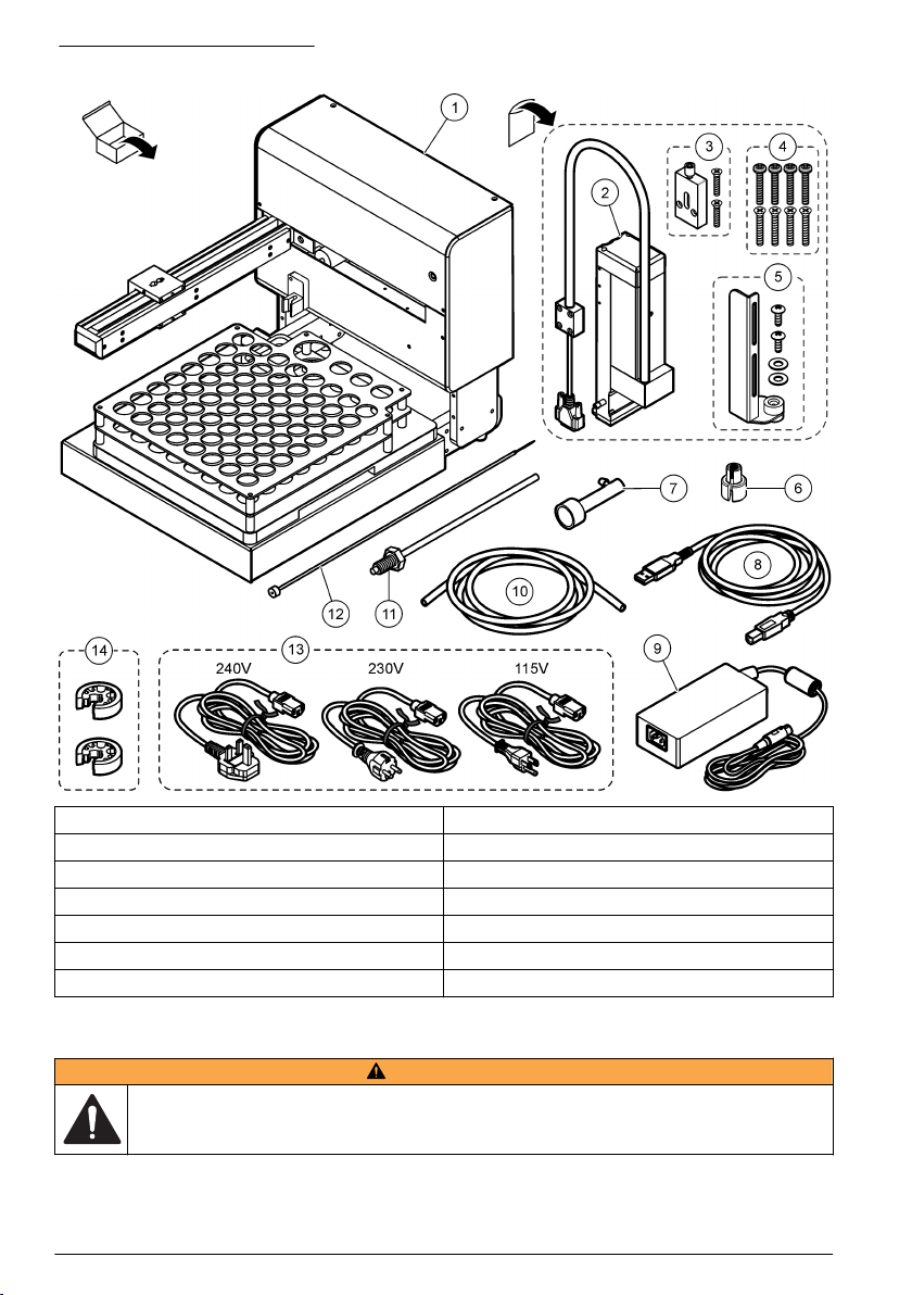
Figure 3 Product components
1 Auto sampler with sample tray 8 USB cable, 3 m
2 Mechanical Z-drive 9 Power supply
3 Vent holder 10 Drain tubing for the rinse station
4 Mechanical Z-drive installation screws (8x) 11 Needle sleeve
5 Stripper plate assembly 12 Sample probe
6 Nut extender tool 13 Power cords (240 V, 230 V, 115 V)
7 Rinse station 14 Tube holders (2x)
Installation
W A R NI N G
Multiple hazards. Only qualified personnel must conduct the tasks described in this section of the
document.
8 English
Page 9

Installation guidelines
Install the instrument:
• On a level surface
• In a clean, dry, well ventilated, temperature controlled location
• In a location with minimum vibrations that has no direct exposure to sunlight
• In a location where there is sufficient clearance around it to make connections and to do
maintenance tasks
• In a location where the power switch and power cord are visible and easily accessible
Mechanical installation
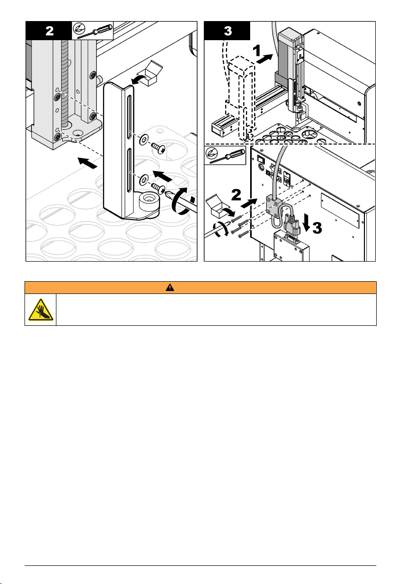
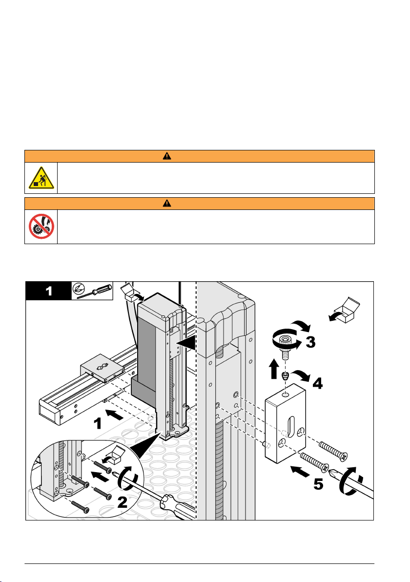
Install the mechanical Z-drive
W A R NI N G
Personal injury hazard. Instruments or components are heavy. Use assistance to install or move.
W A R NI N G
Pinch hazard. Parts that move can pinch and cause injury. Do not touch moving parts.
Refer to the illustrated steps that follow to install the supplied mechanical Z-drive.
Item to collect: Phillips-head screwdriver
English 9
Page 10
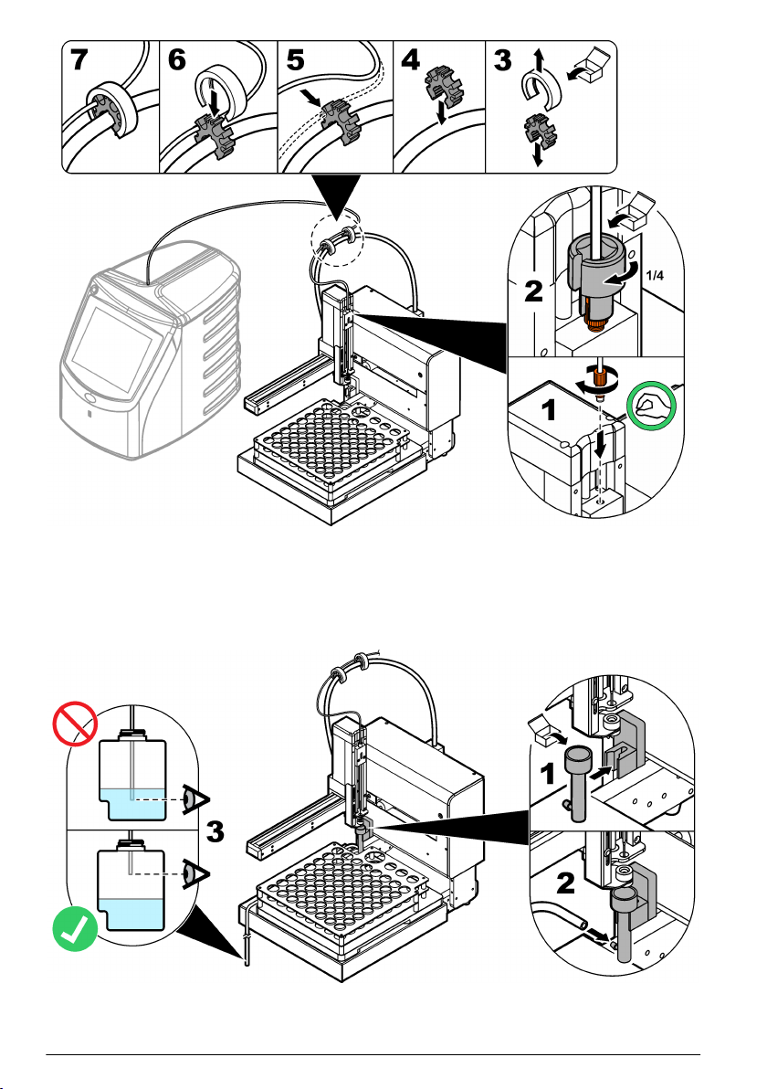
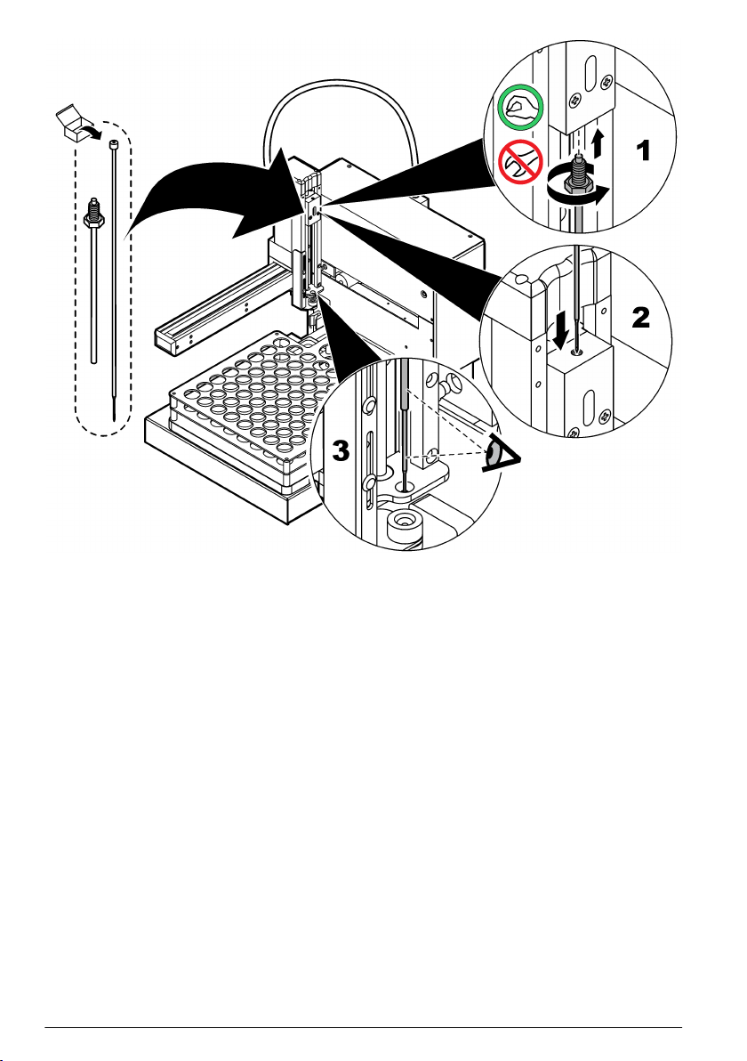
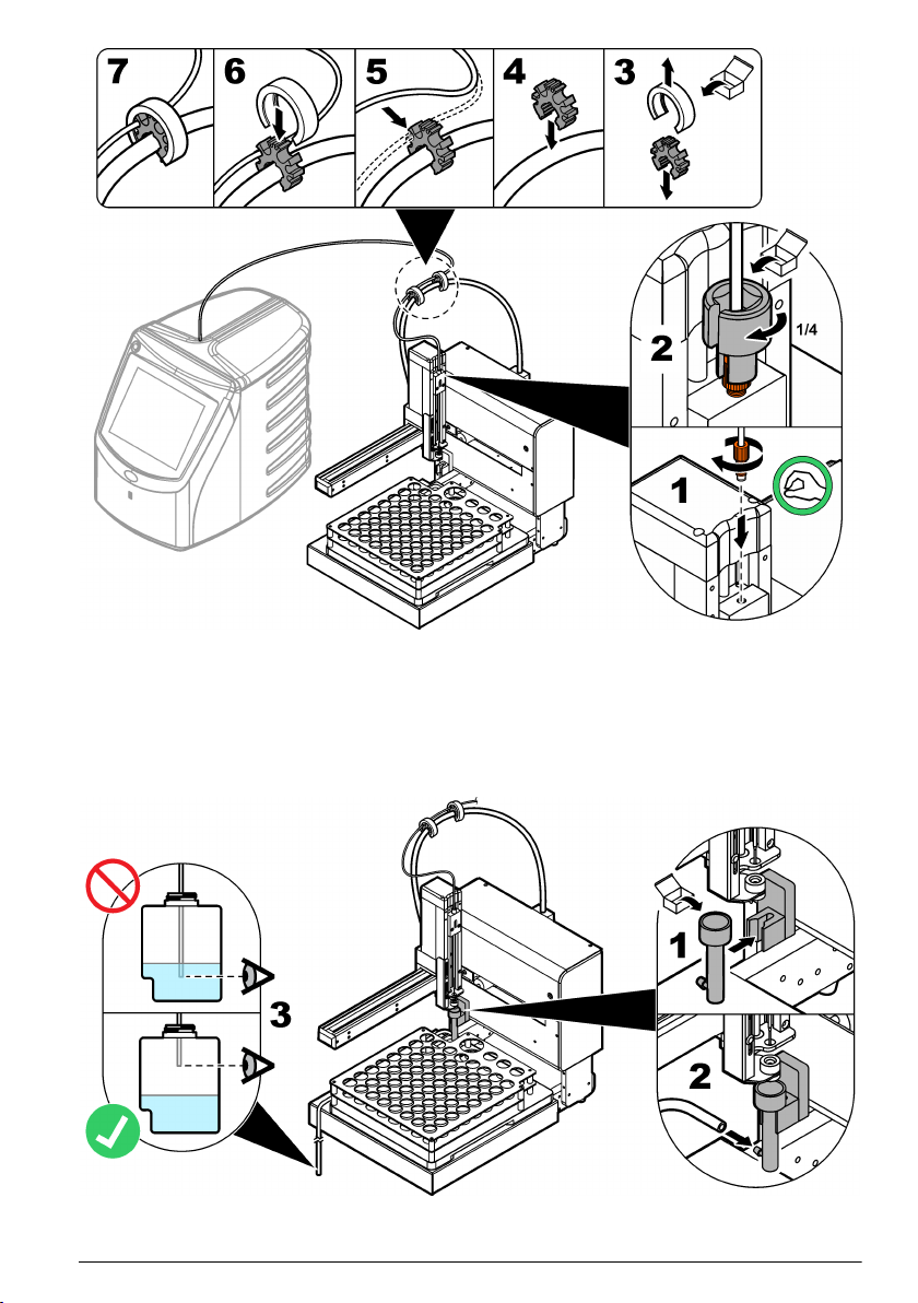
Install the sleeve and the sample probe
W A R NI N G
Puncture injury hazard. Exposed needles can cause puncture wounds. Use caution when bottles are
installed or removed.
Refer to the illustrated steps that follow to install the needle sleeve and the sample probe.
10
English
Page 11

Plumbing
Plumb to the analyzer
Refer to the illustrated steps that follow to connect the sample tube from the analyzer to the
mechanical Z-drive on the auto sampler.
English
11
Page 12
Install the rinse station
After each sample is analyzed, the reagent is flushed through the sample tube to remove the
remaining carbon. The flushed (used) reagent goes to the waste container. If an analyzer is
connected to the instrument, the analyzer controls when the rinse station operates. Refer to the
illustrated steps that follow to install the rinse station and the drain tubing. Make sure to use a
permitted waste container.
12
English
Page 13

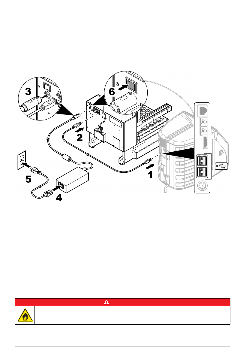
Electrical installation
Connect the analyzer and the power
Before the procedure starts, make sure that the auto sampler and the analyzer power switches are
set to off. Use the supplied USB cable to connect the auto sampler to the analyzer. Use the supplied
power cord and power supply to connect power to the auto sampler. The power for the auto sampler
must be set to on before the analyzer power is set to on. Refer to the analyzer documentation to
connect to power. Refer to the illustrated steps that follow to make the necessary connections.
Startup
Set the power to on
1. Make sure that the power connection is correctly installed. Refer to Connect the analyzer and the
power on page 13.
2. Push the power button on the rear panel of the instrument to set the power to on.
An LED indicator light shows on the front of the instrument when the power is set to on.
3. The arm and the mechanical Z-drive moves, then stops in the correct position.
4. Set the analyzer power to on.
Operation
D A N GE R
Fire hazard. This product is not designed for use with flammable liquids.
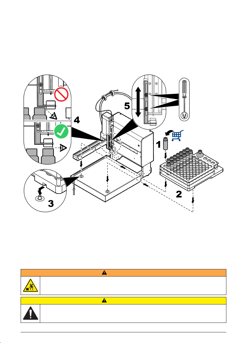
Prepare the instrument for sampling
Refer to the illustrated steps that follow to prepare the instrument for sampling. After sample
collection, put the user-supplied vials in the correct order from one to 64 in the sample tray. Each
sample position is numerically identified on the lower left side.
English
13
Page 14
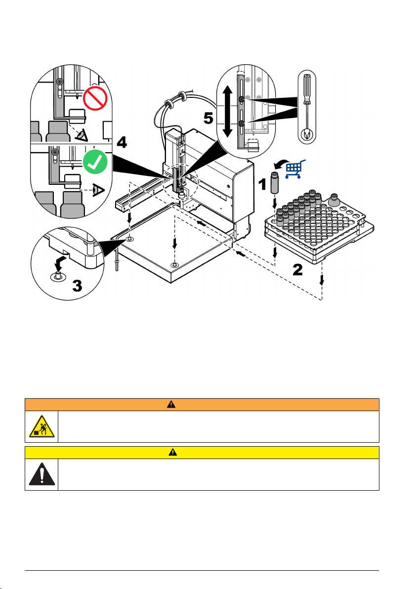
There must be sufficient space between the vials in the sample tray and the platform of the stripper
plate. Refer to the illustrated steps that follow (steps 4 and 5) to make adjustments to the stripper
plate, if necessary.
Carefully install or remove the sample tray to prevent spills.
Do a measurement
Make sure that the vials are correctly installed in the sample tray. Refer to Prepare the instrument for
sampling on page 13. The analyzer controls the measurement parameters. Refer to the analyzer
documentation.
Note: Make sure that all of the necessary plumbing connections are made before this procedure starts. The
analyzer controls the backflush operations to flush the sample flow path.
Maintenance
W A R NI N G
Personal injury hazard. Instruments or components are heavy. Use assistance to install or move.
C A U TI O N
Multiple hazards. Only qualified personnel must conduct the tasks described in this section of the
document.
Note: The manufacturer of the instrument is Teledyne CETAC Technologies. Support services and repairs are
supplied by Hach Company.
Shut-down procedure
Always shut down the instrument before maintenance tasks are done.
14
English
Page 15
1. Set the instrument power to off.
2. Remove the power cord from the power supply.
Do a leak inspection
Inspect for leaks from the sample probe, the sample tube or the rinse station and the rinse station
tubing.
1. Shut down the auto sampler. Refer to the Shut-down procedure on page 14.
2. Examine the sample probe, the sample tube or the rinse station and the rinse station tubing for
damage and evidence of leaks.
3. Replace all of the components that show evidence of leaks or damage.
Clean the instrument
C A U TI O N
Chemical exposure hazard. Obey laboratory safety procedures and wear all of the personal protective
equipment appropriate to the chemicals that are handled. Refer to the current safety data sheets
(MSDS/SDS) for safety protocols.
N O T IC E
Clean the instrument with water. Fumes from cleaning agents can have an effect on the results. Do not let
cleaning agents come into contact with the lead screws. Do not put lubricant on the lead screws.
Spills can occur during use of the instrument. For the best operation, remove spills daily. Clean the
instrument as necessary to prevent instrument damage. Remove contaminants and abrasive material
from moving parts. Remove chemical spills according to MSDS/SDS instructions.
Items to collect:
• Dry, lint-free cloth
• Soft cloth towel
• Clean water
1. Remove the instrument from service. Refer to the Shut-down procedure on page 14.
2. Remove the sample tray.
3. Use the dry, lint-free cloth to remove loose particles from the lead screws.
4. Use the cloth towel to clean the outer surface and base of the instrument.
5. Use clean water to clean the sample tray. Remove all stains and spills.
Note: Make sure to clean the slider block and guide rails along the tube of the arm.
6. Use a dry towel to remove all moisture from the instrument.
Before the power is set to on, let the instrument fully dry.
7. Put the dry sampler tray on the base.
Replace the sample probe
If the probe has leaks or shows signs of damage, replace the probe.
1. Remove the instrument from service. Refer to the Shut-down procedure on page 14.
2. Remove the worn sample probe.
Note: Too much force can damage the mechanical Z-drive.
3. Install the new probe. Refer to Install the mechanical Z-drive on page 9.
English
15
Page 16

Troubleshooting
Problem Possible cause Solution
The instrument does not
operate. The LED status
indicators are off.
The instrument does not
operate. The LED status
indicators are on.
The arm does not operate
correctly.
The sample probe does not pull
up the sample.
The sample probe does not go
through the septum cap of the
vial.
The probe does not easily go
into the mechanical Z-drive.
The sample bottle is lifted up
after the probe retracts.
The power switch is off. Set the power switch to on.
The power cord is disconnected
from the power supply or wall
outlet.
The power cord is damaged. Replace the power cord.
The power supply is faulty. Contact technical support.
The electrical transients on the
power line are too large, which
may disrupt the USB
communication between the
analyzer and the sampler.
The home position of the arm
has damage.
The sample probe is not moving
freely.
The mechanical Z-drive has
damage.
The mechanical Z-drive is not
installed correctly.
The instrument was physically
damaged.
The air flow into vial does not
correctly flow. The sample
tubing is loose.
The stripper plate is not aligned
correctly.
Connect the power cord.
Install any commercially available USB
opto-isolator between the analyzer and the
auto sampler. To repair USB
communications, set the power for both
instruments to off, then to on.
Contact technical support.
Remove the probe to clean and remove
debris. Refer to Replace the sample probe
on page 15.
Replace the sample probe. Refer to
Replace the sample probe on page 15.
Contact technical support.
Validate the installation. Refer to Install the
mechanical Z-drive on page 9.
Set the instrument power to off, then to on.
If the problem continues, contact technical
support.
Examine the sample probe. Make sure that
the needle is inside the metal sleeve.
Tighten the sample tubing connection.
Adjust the height between the vials in the
sample tray and the platform of the stripper
plate. Refer to Prepare the instrument for
sampling on page 13.
Replacement parts and accessories
W A R NI N G
Personal injury hazard. Use of non-approved parts may cause personal injury, damage to the
instrument or equipment malfunction. The replacement parts in this section are approved by the
manufacturer.
Note: Product and Article numbers may vary for some selling regions. Contact the appropriate distributor or refer to
the company website for contact information.
16
English
Page 17

Replacement parts
Description Item no.
Needle sleeve 9467400
Nut extender tool 9454400
Probe, septum piercing SP6790
Power supply 9467300
Sample tray 9467200
English 17
Page 18
Inhaltsverzeichnis
Technische Daten auf Seite 18 Betrieb auf Seite 28
Allgemeine Informationen auf Seite 18 Wartung auf Seite 29
Installation auf Seite 23 Fehlerbehebung auf Seite 31
Inbetriebnahme auf Seite 28 Ersatzteile und Zubehör auf Seite 32
Technische Daten
Änderungen vorbehalten.
Technische Daten Details
Abmessungen (B x T x H) 36,6 x 53,7 x 45,7 cm (14,4 x 21,2 x 18,0 Zoll)
Gehäuse Aluminiumlegierung, Epoxidharz beschichtet
Medienberührte Komponenten. Polyetherimid (PEI) und Polytetrafluoroethylen (PTFE)
Gewicht 21 kg (45 lb)
Einbaukategorie Netzteil: II
Autosampler: I
Verschmutzungsgrad II
Externes Netzteil Eingang: 100–240 V AC, 47–63 Hz, 1,9 A
Ausgang: 24 V DC, 3,33 A
Netzteil des Autosamplers Eingang: 24 V DC, 3,33 A. Nur zum Anschluss an das mitgelieferte Netzteil.
Betriebstemperatur 10 bis 30 ºC (50 bis 85 ºF)
Lagertemperatur 0 bis 55 ºC (32 bis 131 ºF)
Einsatzhöhe Maximal 3048 m (10,000 Fuß)
Relative Luftfeuchtigkeit 0 bis 95% nicht kondensierend
Zertifizierungen CE-Zeichen
Gewährleistung 1 Jahr (EU: 2 Jahre)
Allgemeine Informationen
Der Hersteller ist nicht verantwortlich für direkte, indirekte, versehentliche oder Folgeschäden, die
aus Fehlern oder Unterlassungen in diesem Handbuch entstanden. Der Hersteller behält sich
jederzeit und ohne vorherige Ankündigung oder Verpflichtung das Recht auf Verbesserungen an
diesem Handbuch und den hierin beschriebenen Produkten vor. Überarbeitete Ausgaben der
Bedienungsanleitung sind auf der Hersteller-Webseite erhältlich.
Sicherheitshinweise
H I N WE IS
Der Hersteller ist nicht für Schäden verantwortlich, die durch Fehlanwendung oder Missbrauch dieses Produkts
entstehen, einschließlich, aber ohne Beschränkung auf direkte, zufällige oder Folgeschäden, und lehnt jegliche
Haftung im gesetzlich zulässigen Umfang ab. Der Benutzer ist selbst dafür verantwortlich, schwerwiegende
Anwendungsrisiken zu erkennen und erforderliche Maßnahmen durchzuführen, um die Prozesse im Fall von
möglichen Gerätefehlern zu schützen.
18 Deutsch
Page 19

Bitte lesen Sie dieses Handbuch komplett durch, bevor Sie dieses Gerät auspacken, aufstellen oder
bedienen. Beachten Sie alle Gefahren- und Warnhinweise. Nichtbeachtung kann zu schweren
Verletzungen des Bedieners oder Schäden am Gerät führen.
Stellen Sie sicher, dass die durch dieses Messgerät bereitgestellte Sicherheit nicht beeinträchtigt
wird. Verwenden bzw. installieren Sie das Messsystem nur wie in diesem Handbuch beschrieben.
Bedeutung von Gefahrenhinweisen
G E F AH R
Kennzeichnet eine mögliche oder drohende Gefahrensituation, die, wenn sie nicht vermieden wird, zum Tod oder
zu schweren Verletzungen führt.
Kennzeichnet eine mögliche oder drohende Gefahrensituation, die, wenn sie nicht vermieden wird, zum Tod oder
zu schweren Verletzungen führen kann.
Kennzeichnet eine mögliche Gefahrensituation, die zu geringeren oder moderaten Verletzungen führen kann.
Kennzeichnet eine Situation, die, wenn sie nicht vermieden wird, das Gerät beschädigen kann. Informationen, die
besonders beachtet werden müssen.
W A R NU N G
V O R SI C H T
H I N WE IS
Warnhinweise
Lesen Sie alle am Gerät angebrachten Aufkleber und Hinweise. Nichtbeachtung kann Verletzungen
oder Beschädigungen des Geräts zur Folge haben.
Dieses Symbol am Gerät weist auf Betriebs- und/oder Sicherheitsinformationen im Handbuch hin.
Elektrogeräte, die mit diesem Symbol gekennzeichnet sind, dürfen nicht im normalen öffentlichen
Abfallsystem entsorgt werden. Senden Sie Altgeräte an den Hersteller zurück. Dieser entsorgt die
Geräte ohne Kosten für den Benutzer.
Dieses Symbol weist auf die Gefahr eines elektrischen Schlages hin, der tödlich sein kann.
Dieses Symbol weist darauf hin, dass die Hand von oben gequetscht werden kann.
Dieses Symbol weist auf eine mögliche Stich- oder Klemmgefahr hin. Halten Sie Hände und Finger
fern.
Dieses Symbol weist auf einen schweren Gegenstand hin.
Zertifizierung
Kanadische Vorschriften zu Störungen verursachenden Einrichtungen, IECS-003, Klasse A:
Entsprechende Prüfprotokolle hält der Hersteller bereit.
Deutsch
19
Page 20

Dieses digitale Gerät der Klasse A erfüllt alle Vorgaben der kanadischen Normen für Interferenz
verursachende Geräte.
Cet appareil numérique de classe A répond à toutes les exigences de la réglementation canadienne
sur les équipements provoquant des interférences.
FCC Teil 15, Beschränkungen der Klasse "A"
Entsprechende Prüfprotokolle hält der Hersteller bereit. Das Gerät entspricht Teil 15 der FCCVorschriften. Der Betrieb unterliegt den folgenden Bedingungen:
1. Das Gerät darf keine Störungen verursachen.
2. Das Gerät muss jegliche Störung, die es erhält, einschließlich jener Störungen, die zu
unerwünschtem Betrieb führen, annehmen.
Änderungen oder Modifizierungen an diesem Gerät, die nicht ausdrücklich durch die für die
Einhaltung der Standards verantwortliche Stelle bestätigt wurden, können zur Aufhebung der
Nutzungsberechtigung für dieses Gerät führen. Dieses Gerät wurde geprüft, und es wurde
festgestellt, dass es die Grenzwerte für digitale Geräte der Klasse A entsprechend Teil 15 der FCCVorschriften einhält. Diese Grenzwerte sollen einen angemessenen Schutz gegen
gesundheitsschädliche Störungen gewährleisten, wenn dieses Gerät in einer gewerblichen
Umgebung betrieben wird. Dieses Gerät erzeugt und nutzt hochfrequente Energie und kann diese
auch abstrahlen, und es kann, wenn es nicht in Übereinstimmung mit der Bedienungsanleitung
installiert und eingesetzt wird, schädliche Störungen der Funkkommunikation verursachen. Der
Betrieb dieses Geräts in Wohngebieten kann schädliche Störungen verursachen. In diesem Fall
muss der Benutzer die Störungen auf eigene Kosten beseitigen. Probleme mit Interferenzen lassen
sich durch folgende Methoden mindern:
1. Trennen Sie das Gerät von der Stromversorgung, um sicherzugehen, dass dieser die Störungen
nicht selbst verursacht.
2. Wenn das Gerät an die gleiche Steckdose angeschlossen ist wie das gestörte Gerät, schließen
Sie das störende Gerät an eine andere Steckdose an.
3. Vergrößern Sie den Abstand zwischen diesem Gerät und dem gestörten Gerät.
4. Ändern Sie die Position der Empfangsantenne des gestörten Geräts.
5. Versuchen Sie auch, die beschriebenen Maßnahmen miteinander zu kombinieren.
Produktübersicht
Der Autosampler QbD1200 ist ein automatischer Probenwechsler, der in analytischen Laboren zur
TOC-Analyse wässriger Proben verwendet wird. Das Gerät verfügt über ein Gestell mit Kapazität für
maximal 64 Küvetten, eine Kalibrierflasche und drei Flaschen für Systemeignungstests. Das Gerät
arbeitet weitgehend ohne Benutzereingriffe und wird zusammen mit dem TOC-Analysegerät
QbD1200 verwendet. Eine Übersicht über das Gerät finden Sie unter Abbildung 1 und Abbildung 2.
Hinweis: Der Hersteller des Geräts is Teledyne CETAC Technologies. Support-Dienstleistungen und Reparaturen
werden durch Hach Company bereitgestellt.
20
Deutsch
Page 21

Abbildung 1 Produktübersicht
1 Arm 8 Probenansaugröhrchen
2 Spülstation 9 Betriebsleuchte
3 Abstreifer 10 Halterung für Kalibrierstandard
4 Mechanischer Z-Antrieb 11 Halterungen für Systemeignungstests
5 Probenschlauch (vom Analysegerät) 12 Probenpositionen (1 bis 64)
6 Röhrchenhalter 13 Gestell
7 Nadelhülse 14 Ablaufschlauch der Spülstation
Deutsch 21
Page 22

Abbildung 2 Übersicht Rückseite
1 Netzschalter 5 Anschluss für das Kabel des mechanischen Z-
2 COM-Port 2
3 Ethernet-Anschluss
4 Kabel für den mechanischen Z-Antrieb 8 Stromversorgungsanschluss
1
1
Antriebs
6 COM-Port 1
7 USB-Anschluss
1
Produktkomponenten
Stellen Sie sicher, dass Sie alle Teile erhalten haben. Siehe Abbildung 3. Wenn Komponenten fehlen
oder beschädigt sind, kontaktieren Sie bitte den Hersteller oder Verkäufer.
1
Diese Funktionen werden nicht verwendet.
22 Deutsch
Page 23

Abbildung 3 Produktkomponenten
1 Autosampler mit Gestell 8 USB-Kabel, 3 m
2 Mechanischer Z-Antrieb 9 Netzteil
3 Lüftungshalterung 10 Ablaufschläuche für Spülstation
4 Befestigungsschrauben für den mechanischen Z-
Antrieb (8x)
5 Abstreiferplatten-Baugruppe 12 Probenansaugröhrchen
6 Verlängerungsaufsatz 13 Netzkabel (240 V, 230 V, 115 V)
7 Spülstation 14 Röhrchenhalter (2x)
11 Nadelhülse
Installation
W A R NU N G
Mehrere Gefahren. Nur qualifiziertes Personal sollte die in diesem Kapitel des Dokuments
beschriebenen Aufgaben durchführen.
Deutsch 23
Page 24
Installationsanleitung
Installation des Gerätes:
• Auf einem ebenen Untergrund
• An einem sauberen, trockenen, gut belüfteten, klimatisierten Standort
• An einem Standort mit minimalen Vibrationen, an dem es keine direkte Sonneneinstrahlung gibt
• An einem Standort mit ausreichend Platz für Anschluss- und Wartungsarbeiten
• An einem Standort, an dem der Netzschalter und das Netzkabel sichtbar und leicht zugänglich
sind
Mechanische Installation
Installieren des mechanischen Z-Antriebs
W A R NU N G
Verletzungsgefahr. Geräte oder Komponenten sind schwer. Bewegen oder installieren Sie diese nicht
allein.
W A R NU N G
Klemmgefahr Bewegliche Teile bergen Klemmgefahr und können Verletzungen verursachen. Berühren
Sie keine beweglichen Teile.
Befolgen Sie zur Installation des mitgelieferten mechanischen Z-Antriebs die nachfolgend
abgebildeten Schritte.
Zusätzlich erforderliche Artikel: Kreuzschlitz-Schraubendreher
24 Deutsch
Page 25

Installieren der Hülse und des Probenansaugröhrchens
W A R NU N G
Gefahr durch Stichverletzungen. Herausstehende Nadeln können Stichverletzungen verursachen.
Seien Sie vorsichtig, wenn Sie Flaschen installieren oder entfernen.
Befolgen Sie zur Installation der Nadelhülse und des Probenansaugröhrchens die nachfolgend
abgebildeten Schritte.
Deutsch
25
Page 26
Montage der Schläuche
Anschließen an das Analysegerät
Befolgen Sie zum Anschluss des Analysegerät-Probenschlauchs an den mechanischen Z-Antrieb
des Autosamplers die nachfolgend abgebildeten Schritte.
26
Deutsch
Page 27
Installieren der Spülstation
Nach der Analyse aller Proben wird das Reagenz durch den Probenschlauch gespült, um
Kohlenstoffrückstände zu entfernen. Nach dem Spülen fließt das (gebrauchte) Reagenz in den
Abwasserbehälter. Wenn das Analysegerät an das Gerät angeschlossen ist, steuert das
Analysegerät den Einsatz der Spülstation. Befolgen Sie zur Installation der Spülstation und der
Ablaufschläuche die nachfolgend abgebildeten Schritte. Stellen Sie sicher, dass ein zulässiger
Abwasserbehälter verwendet wird.
Deutsch
27
Page 28
Elektrische Installation
Schließen Sie das Analysegerät und die Spannungsversorgung an.
Stellen Sie vor Beginn des Verfahrens sicher, dass die Netzschalter von Analysegerät und
Autosampler auf „Aus“ stehen. Schließen Sie den Autosampler mit dem mitgelieferten USB-Kabel an
das Analysegerät an. Schließen Sie den Autosampler mit dem mitgelieferten Netzkabel und dem
Netzteil an eine Spannungsversorgung an. Der Netzschalter des Autosamplers muss vor dem
Netzschalter des Analysegeräts auf „An“ gestellt werden. Anweisungen zum Netzanschluss des
Analysegeräts finden Sie in der entsprechenden Dokumentation. Befolgen Sie die abgebildeten
Schritte, um die erforderlichen Anschlüsse vorzunehmen.
Inbetriebnahme
Einschalten
1. Stellen Sie sicher, dass der Netzanschluss korrekt installiert ist. Siehe Schließen Sie das
Analysegerät und die Spannungsversorgung an. auf Seite 28.
2. Drücken Sie den Netzschalter auf der Rückseite, um das Geräts einzuschalten.
Eine LED-Statusanzeige auf der Vorderseite des Geräts zeigt an, wenn das Gerät eingeschaltet
ist.
3. Der Arm und der mechanische Z-Antrieb bewegen sich und bleiben in der richtigen Position
stehen.
4. Schalten Sie das Analysegerät ein.
Betrieb
G E F AH R
Brandgefahr. Dieses Produkt ist nicht für den Gebrauch mit entzündbaren Flüssigkeiten geeignet.
28 Deutsch
Page 29
Vorbereiten des Geräts für die Probenentnahme
Befolgen Sie zur Vorbereitung des Geräts für die Probenentnahme die nachfolgend abgebildeten
Schritte. Setzten Sie die benutzereigenen Küvetten nach der Probenentnahme in der richtigen
Reihenfolge von 1 bis 64 in das Gestell ein. Jede Probenposition ist unten links numerisch
gekennzeichnet.
Zwischen den Küvetten im Gestell und der Plattform des Abstreifers muss ausreichend Platz sein.
Befolgen Sie zur Anpassung des Abstreifers die nachfolgend abgebildeten Schritte (Schritte 4 und
5).
Gehen Sie beim Einsetzen und Entnehmen des Gestells vorsichtig vor, damit kein Material
verschüttet wird.
Durchführen von Messungen
Stellen Sie sicher, dass die Küvetten ordnungsgemäß im Gestell eingesetzt sind. Siehe Vorbereiten
des Geräts für die Probenentnahme auf Seite 29. Das Analysegerät steuert die Messparameter.
Siehe Dokumentation zum Analysegerät.
Hinweis: Stellen Sie vor Beginn des Verfahrens sicher, dass alle erforderlichen Leitungsanschlüsse korrekt sind.
Der Analysegerät steuert die Rückflussvorgänge zum Spülen des Probenströmungswegs.
Wartung
W A R NU N G
Verletzungsgefahr. Geräte oder Komponenten sind schwer. Bewegen oder installieren Sie diese nicht
allein.
V O R SI C H T
Mehrere Gefahren. Nur qualifiziertes Personal sollte die in diesem Kapitel des Dokuments
beschriebenen Aufgaben durchführen.
Deutsch 29
Page 30

Hinweis: Der Hersteller des Geräts is Teledyne CETAC Technologies. Support-Dienstleistungen und Reparaturen
werden durch Hach Company bereitgestellt.
Abschalten des Geräts
Schalten Sie das Gerät stets aus, bevor Sie Wartungsarbeiten durchführen.
1. Schalten Sie das Gerät aus.
2. Ziehen Sie das Netzkabel aus der Steckdose.
Prüfen der Dichtigkeit
Prüfen Sie Probenansaugröhrchen, Probenschlauch, Spülstation und Schläuche der Spülstation auf
Dichtigkeit.
1. Schalten Sie den Autosampler aus. Siehe Abschalten des Geräts auf Seite 30.
2. Prüfen Sie Probenansaugröhrchen, Probenschlauch, Spülstation und Schläuche der Spülstation
auf Beschädigungen oder Anzeichen von Leckagen.
3. Tauschen Sie alle Komponenten aus, die Anzeichen von Leckagen oder Schäden zeigen.
Reinigung des Geräts
V O R SI C H T
Gefahr von Kontakt mit Chemikalien. Halten Sie sich an die Sicherheitsmaßnahmen im Labor, und
tragen Sie Schutzkleidung entsprechend den Chemikalien, mit denen Sie arbeiten. Beachten Sie die
Sicherheitsprotokolle in den aktuellen Materialsicherheitsdatenblättern (MSDS/SDB).
H I N WE IS
Reinigen Sie das Gerät mit Wasser. Dämpfe von Reinigungsmitteln können die Ergebnisse beeinflussen. Lassen
Sie keine Reinigungsmittel auf die Spindeln gelangen. Tragen Sie kein Schmiermittel auf die Spindeln auf.
Bei der Verwendung des Geräts kann Flüssigkeit auslaufen. Entfernen Sie ausgelaufene Flüssigkeit
täglich, um einen optimalen Betrieb zu gewährleisten. Reinigen Sie das Gerät, wenn erforderlich, um
eine Beschädigung des Geräts zu verhindern. Entfernen Sie Verunreinigungen und scheuernde
Stoffe von den beweglichen Teilen. Nehmen Sie ausgelaufene Chemikalien wie in den
Sicherheitsdatenblättern beschrieben auf.
Zusätzlich erforderliche Artikel:
• Trockenes, fusselfreies Tuch
• Weiches Textiltuch
• Sauberes Wasser
1. Nehmen Sie das Gerät außer Betrieb. Siehe Abschalten des Geräts auf Seite 30.
2. Entnehmen Sie das Gestell.
3. Wischen Sie lose Ablagerungen mit einem trockenen, fusselfreien Tuch von den Spindeln.
4. Reinigen Sie die äußere Oberfläche und den Sockel des Geräts mit einem Tuch.
5. Reinigen Sie das Gestell mit Wasser. Entfernen Sie alle Flecken und ausgelaufenes Material.
Hinweis: Reinigen Sie unbedingt den Schieberblock und die Führungsschienen entlang des Schlauchs am
Arm.
6. Trocknen Sie das Gerät mit einem trockenen Tuch gut ab.
Lassen Sie das Gerät vollständig trocknen, bevor Sie die Spannungsversorgung einschalten.
7. Stellen Sie das Gestell auf den Sockel
30
Deutsch
Page 31

Ersetzen des Probenansaugröhrchens
Wenn das Ansaugröhrchen Anzeichen von Leckagen oder Schäden zeigt, tauschen Sie es aus.
1. Nehmen Sie das Gerät außer Betrieb. Siehe Abschalten des Geräts auf Seite 30.
2. Entfernen Sie das verschlissene Probenansaugröhrchen.
Hinweis: Eine zu hohe Kraft kann den mechanischen Z-Antrieb beschädigen.
3. Setzen Sie das neue Ansaugröhrchen ein. Siehe Installieren des mechanischen Z-Antriebs
auf Seite 24.
Fehlerbehebung
Problem Mögliche Ursache Lösung
Das Gerät funktioniert nicht. Die
LED-Statusanzeigen leuchten
nicht.
Das Gerät funktioniert nicht. Die
LED-Statusanzeigen leuchten.
Der Arm funktioniert nicht richtig. Das Gerät wurde physisch
Das Probenansaugröhrchen
saugt die Probe nicht an.
Der Netzschalter steht auf
„Aus“.
Das Netzkabel ist aus dem
Netzteil oder der Steckdose
herausgezogen.
Das Netzkabel ist beschädigt. Tauschen Sie das Netzkabel aus.
Das Netzteil ist defekt. Wenden Sie sich an den technischen
Die elektrischen
Störspannungen in der
Stromleitung sind zu hoch, was
die USB-Datenübertragung
zwischen Analysegerät und
Autosampler beeinträchtigen
kann.
Die Ausgangsposition des Arms
ist beschädigt.
Das Probenansaugröhrchen ist
nicht frei beweglich.
Der mechanische Z-Antrieb ist
beschädigt.
Der mechanische Z-Antrieb ist
nicht korrekt installiert.
beschädigt.
Der Luftstrom in die Küvette
strömt nicht richtig. Die
Probenschläuche sind locker.
Stellen Sie den Netzschalter auf „Ein“.
Schließen Sie das Netzkabel an.
Support.
Installieren Sie einen handelsüblichen
USB-Optokoppler zwischen dem
Analysegerät und dem Autosampler.
Schalten Sie zur Wiederherstellung der
USB-Datenübertragung beide Geräte aus
und wieder ein.
Wenden Sie sich an den technischen
Support.
Entfernen Sie das Probenansaugröhrchen,
um es zu reinigen und Ablagerungen zu
entfernen. Siehe Ersetzen des
Probenansaugröhrchens auf Seite 31.
Tauschen Sie das Probenansaugröhrchen
aus. Siehe Ersetzen des
Probenansaugröhrchens auf Seite 31.
Wenden Sie sich an den technischen
Support.
Validieren der Installation. Siehe
Installieren des mechanischen Z-Antriebs
auf Seite 24.
Schalten Sie das Gerät aus und dann
wieder ein. Wenn das Problem weiterhin
besteht, wenden Sie sich an den
technischen Support.
Prüfen Sie das Probenansaugröhrchen.
Stellen Sie sicher, dass die Nadel sich in
der Metallhülse befindet. Ziehen Sie die
Probenschlauchanschlüsse fest.
Deutsch 31
Page 32

Problem Mögliche Ursache Lösung
Das Probenansaugröhrchen
durchsticht die Septumkappe der
Küvette nicht.
Das Ansaugröhrchen bewegt
sich nicht störungsfrei in dem
mechanischen Z-Antrieb.
Die Probenflasche wird
angehoben, nachdem das
Ansaugröhrchen herausgezogen
wurde.
Der Abstreifer ist nicht richtig
ausgerichtet.
Passen Sie den Abstand zwischen den
Küvetten im Gestell und der Plattform des
Abstreifers an. Siehe Vorbereiten des
Geräts für die Probenentnahme
auf Seite 29.
Ersatzteile und Zubehör
W A R NU N G
Verletzungsgefahr. Die Verwendung nicht zugelassener Teile kann zur Verletzung von Personen, zu
Schäden am Messgerät oder zu Fehlfunktionen der Ausrüstung führen. Die Ersatzteile in diesem
Abschnitt sind vom Hersteller zugelassen.
Hinweis: Produkt- und Artikelnummern können für einige Verkaufsgebiete abweichen. Wenden Sie sich an den
zuständigen Distributor oder schlagen Sie die Kontaktinformationen auf der Webseite des Unternehmens nach.
Ersatzteile
Beschreibung Bestellnr.
Nadelhülse 9467400
Verlängerungsaufsatz 9454400
Ansaugröhrchen, Septum-Durchstechung SP6790
Netzteil 9467300
Gestell 9467200
32 Deutsch
Page 33

Sommario
Dati tecnici a pagina 33 Funzionamento a pagina 43
Informazioni generali a pagina 33 Manutenzione a pagina 44
Installazione a pagina 38 Diagnostica a pagina 46
Avviamento a pagina 43 Parti di ricambio e accessori a pagina 47
Dati tecnici
I dati tecnici sono soggetti a modifica senza preavviso.
Dato tecnico Dettagli
Dimensioni (L x P x A) 36,6 x 53,7 x 45,7 cm (14,4 x 21,2 x 18,0 poll.)
Carter Lega di alluminio, cromato con uno strato di polvere epossidica
Componenti Polieterimide (PEI) e politetrafluoroetilene (PTFE)
Peso 21 kg (45 libbre)
Categoria di installazione Alimentatore: II
Autocampionatore: I
Grado di inquinamento II
Alimentatore esterno Ingresso: 100-240 VCA, 47/63 Hz, 1,9 A
Uscita: 24 V c.c., 3,33 A
Alimentazione dell'autocampionatore Ingresso: 24 V c.c., 3,33 A. Utilizzare solo con l'alimentatore in dotazione.
Temperatura di esercizio Da 10 a 30 ºC (da 50 a 85 ºF)
Temperatura di conservazione Da 0 a 55 ºC (da 32 a 131 ºF)
Altitudine 3048 m massimo
Umidità relativa Da 0% a 95%
Certificazioni Contrassegno CE
Garanzia 1 anno (EU: 2 anni)
Informazioni generali
In nessun caso, il produttore potrà essere ritenuto responsabile per danni diretti, indiretti o accidentali
per qualsiasi difetto o omissione relativa al presente manuale. Il produttore si riserva il diritto di
apportare eventuali modifiche al presente manuale e ai prodotti ivi descritti in qualsiasi momento
senza alcuna notifica o obbligo preventivi. Le edizioni riviste sono presenti nel sito Web del
produttore.
Informazioni sulla sicurezza
A V V IS O
Il produttore non sarà da ritenersi responsabile in caso di danni causati dall'applicazione errata o dall'uso errato di
questo prodotto inclusi, a puro titolo esemplificativo e non limitativo, i danni incidentali e consequenziali; inoltre
declina qualsiasi responsabilità per tali danni entro i limiti previsti dalle leggi vigenti. La responsabilità relativa
all'identificazione dei rischi critici dell'applicazione e all'installazione di meccanismi appropriati per proteggere le
attività in caso di eventuale malfunzionamento dell'apparecchiatura compete unicamente all'utilizzatore.
Italiano 33
Page 34

Prima di disimballare, installare o utilizzare l’apparecchio, si prega di leggere l’intero manuale. Si
raccomanda di leggere con attenzione e rispettare le istruzioni riguardanti note di pericolosità. La non
osservanza di tali indicazioni potrebbe comportare lesioni gravi all'operatore o danni all'apparecchio.
Assicurarsi che i dispositivi di sicurezza insiti nell'apparecchio siano efficaci all'atto della messa in
servizio e durante l'utilizzo dello stesso. Non utilizzare o installare questa apparecchiatura in modo
diverso da quanto specificato nel presente manuale.
Indicazioni e significato dei segnali di pericolo
P E R IC O L O
Indica una situazione di pericolo potenziale o imminente che, se non evitata, causa lesioni gravi anche mortali.
A V V ER T E N Z A
Indica una situazione di pericolo potenziale o imminente che, se non evitata, potrebbe comportare lesioni gravi,
anche mortali.
A T T EN ZI O N E
Indica una situazione di pericolo potenziale che potrebbe comportare lesioni lievi o moderate.
Indica una situazione che, se non evitata, può danneggiare lo strumento. Informazioni che richiedono particolare
attenzione da parte dell'utente.
A V V IS O
Etichette e simboli presenti sull'analizzatore
Verificare e prendere visione delle indicazioni e delle targhette di segnalazione applicate
all'apparecchio. La mancata osservanza delle stesse può infatti causare lesioni personali o danni allo
strumento.
Tale simbolo, se apposto sullo strumento, fa riferimento al manuale delle istruzioni per il
funzionamento e/o informazioni sulla sicurezza.
Le apparecchiature elettriche contrassegnate con questo simbolo non possono essere smaltite
attraverso sistemi domestici o pubblici europei. Restituire le vecchie apparecchiature al produttore il
quale si occuperà gratuitamente del loro smaltimento.
Questo simbolo indica un rischio di scosse elettriche e/o elettrocuzione.
Questo simbolo indica un pericolo che può schiacciare una mano dall'alto.
Questo simbolo indica un pericolo di puntura o pizzicamento. Tenere mani e dita lontane.
Questo simbolo indica che l'oggetto è pesante.
Certificazioni
Canadian Radio Interference-Causing Equipment Regulation, IECS-003, Class A:
Le registrazioni dei test di supporto sono disponibili presso il produttore.
34
Italiano
Page 35

Questo apparecchio digitale di Classe A soddisfa tutti i requisiti di cui agli Ordinamenti canadesi sulle
apparecchiature causanti interferenze.
Questo apparecchio digitale di Classe A soddisfa tutti i requisiti di cui agli Ordinamenti canadesi sulle
apparecchiature causanti interferenze.
FCC Parte 15, Limiti Classe "A"
Le registrazioni dei testi di supporto sono disponibili presso il produttore. Il presente dispositivo è
conforme alla Parte 15 della normativa FCC. Il funzionamento è subordinato alle seguenti condizioni:
1. L'apparecchio potrebbe non causare interferenze dannose.
2. L'apparecchio deve tollerare tutte le interferenze subite, comprese quelle causate da
funzionamenti inopportuni.
Modifiche o cambiamenti eseguiti sull’unità senza previa approvazione da parte dell'ente
responsabile della conformità potrebbero annullare il diritto di utilizzare l'apparecchio. Questo
apparecchio è stato testato ed è conforme con i limiti per un dispositivo digitale di Classe A, secondo
la Parte 15 delle normative FCC. I suddetti limiti sono stati fissati in modo da garantire una
protezione adeguata nei confronti di interferenze nocive se si utilizza l’apparecchiatura in applicazioni
commerciali. L’apparecchiatura produce, utilizza e può irradiare energia a radiofrequenza e, se non
installata e utilizzata in accordo a quanto riportato nel manuale delle istruzioni, potrebbe causare
interferenze nocive per le radiocomunicazioni. L'utilizzo di questa apparecchiatura in una zona
residenziale può provocare interferenze dannose; in tal caso, l'utente dovrà eliminare l'interferenza a
proprie spese. Per ridurre i problemi di interferenza, è possibile utilizzare le seguenti tecniche:
1. Scollegare l'apparecchio dalla sua fonte di potenza per verificare che sia la fonte dell’interferenza
o meno.
2. Se l'apparecchio è collegato alla stessa uscita del dispositivo in cui si verifica l'interferenza,
collegare l'apparecchio ad un'uscita differente.
3. Spostare l'apparecchio lontano dal dispositivo che riceve l'interferenza.
4. Posizionare nuovamente l’antenna di ricezione dell’apparecchio che riceve le interferenze.
5. Provare una combinazione dei suggerimenti sopra riportati.
Descrizione del prodotto
L'autocampionatore QbD1200 è un cambiacampioni automatico utilizzato nei laboratori per le analisi
TOC di campioni acquosi. Lo strumento dispone di un vassoio per campioni in grado di contenere un
massimo di 64 fiale per campioni, un flacone di calibrazione e tre flaconi per i test di adeguatezza del
sistema. Lo strumento agisce con interventi minimi da parte dell'utente e viene utilizzato con
l'analizzatore QbD1200 TOC. Fare riferimento a Figura 1 e Figura 2 per una panoramica dello
strumento.
Nota: Il produttore dello strumento è Teledyne CETAC Technologies. I servizi di assistenza e riparazione sono
garantiti da Hach Company
Italiano
35
Page 36

Figura 1 Descrizione del prodotto
1 Braccio 8 Sonda campione
2 Stazione di risciacquo 9 Spia di alimentazione
3 Paratia di protezione 10 Posizione per lo standard di calibrazione
4 Unità asse Z 11 Posizione per i test di adeguatezza del sistema
5 Tubo di campionamento 12 Posizioni campioni (da 1 a 64)
6 Supporti tubi 13 Vassoio campioni
7 Guaina dell'ago 14 Stazione di risciacquo e tubo di scarico
36 Italiano
Page 37

Figura 2 Panoramica pannello posteriore
1 Pulsante di accensione 5 Collegamento cavo unità Z meccanica
2 Porta COM 2
3 Porta Ethernet
4 Cavo unità Z meccanica 8 Connettore di alimentazione
1
1
6 Porta COM 1
7 Porta USB
1
Componenti del prodotto
Verificare che le componenti ricevute siano conformi all'ordine di acquisto. Fare riferimento a
Figura 3. In caso di componenti mancanti o danneggiati, contattare immediatamente il produttore o il
rappresentante.
1
Componenti non in uso.
Italiano 37
Page 38

Figura 3 Componenti del prodotto
1 Autocampionatore con vassoio dei campioni 8 Cavo USB, 3 m
2 Unità asse Z 9 Alimentatore
3 Supporto aerazione 10 Tubazione di scarico della stazione di risciacquo
4 Viti di installazione dell'unità Z meccanica (8x) 11 Guaina dell'ago
5 Piastra di estrazione 12 Sonda campione
6 Utensile estensore dado 13 Cavi di alimentazione (240 V, 230 V, 115 V)
7 Stazione di risciacquo 14 Supporti tubi (2x)
Installazione
A V V ER T E N Z A
Pericoli multipli. Gli interventi descritti in questa sezione del documento devono essere eseguiti solo da
personale qualificato.
38 Italiano
Page 39

Linee guida di installazione
Installare lo strumento:
• Su una superficie piana
• In un luogo pulito, asciutto, ben ventilato e con temperatura controllata
• In un luogo con vibrazioni limitate e non esposto alla luce solare diretta
• In un luogo dove è presente spazio sufficiente attorno allo strumento per effettuare i vari
collegamenti e per gli eventuali interventi di manutenzione
• In un luogo da cui siano visibili e facilmente accessibili l'interruttore e il cavo di alimentazione.
Installazione
Collegamento dell'asse Z
A V V ER T E N Z A
Pericolo di lesioni personali. Gli strumenti o i componenti sono pesanti. Per l'installazione o lo
spostamento richiedere assistenza.
A V V ER T E N Z A
Pericolo di schiacciamento. Gli organi mobili possono causare lesioni dovute a schiacciamento. Non
toccare gli organi mobili.
Fare riferimento ai passaggi illustrati seguenti per installare l'unità Z meccanica in dotazione.
Attrezzi necessari: cacciavite Phillips
Italiano 39
Page 40

Installazione della guaina e della sonda campione
A V V ER T E N Z A
Pericolo di lesioni da puntura. Gli aghi esposti possono causare ferite da puntura. Durante
l'installazione e la rimozione dei flaconi, procedere con cautela.
Fare riferimento ai passaggi illustrati seguenti per installare la guaina dell'ago e la sonda campione.
40
Italiano
Page 41

Collegamento idraulico
Collegamento dell'analizzatore
Fare riferimento ai passaggi illustrati seguenti per collegare il tubo del campione dall'analizzatore
all'asse Z sull'autocampionatore.
Italiano
41
Page 42

Installazione della stazione di risciacquo
Dopo l'analisi di ciascun campione, il reagente viene scaricato attraverso il tubo di campionamento,
allo scopo di evitare problemi di inquinamento del campione successivo. Il reagente usato viene
immesso nel contenitore di scarico. Se un analizzatore è collegato allo strumento, l'analizzatore
controlla quando la stazione di risciacquo è in funzione. Fare riferimento alle fasi illustrate seguenti
per l'installazione della stazione di risciacquo e del circuito di scarico. Utilizzare un contenitore
idoneo per lo scarico.
42
Italiano
Page 43

Installazione elettrica
Collegamento dell'analizzatore e dell'alimentazione
Prima di iniziare la procedura, verificare che gli interruttori di alimentazione dell'autocampionatore e
dell'analizzatore siano posizionati su off. Utilizzare il cavo USB in dotazione per collegare
l'autocampionatore all'analizzatore. Utilizzare il cavo di alimentazione e l'alimentatore per alimentare
l'autocampionatore. L'alimentazione dell'autocampionatore deve essere attiva prima di alimentare
l'analizzatore. Fare riferimento alla documentazione dell'analizzatore per il collegamento
dell'alimentazione. Fare riferimento ai passaggi illustrati seguenti per effettuare i collegamenti
necessari.
Avviamento
Accensione
1. Verificare che il collegamento dell'alimentazione sia installato correttamente. Fare riferimento a
Collegamento dell'analizzatore e dell'alimentazione a pagina 43.
2. Premere il pulsante di alimentazione sul pannello posteriore per attivare l'alimentazione.
Un indicatore luminoso a LED indica nella parte anteriore dello strumento quando l'alimentazione
è attiva.
3. Il braccio e l'unità Z si muovono, quindi si arrestano nella posizione corretta.
4. Alimentare l'analizzatore.
Funzionamento
P E R IC O L O
Pericolo di incendio. Questo prodotto non è stato concepito per l'uso con liquidi infiammabili.
Italiano 43
Page 44

Preparazione dello strumento per il campionamento
Fare riferimento ai passaggi illustrati seguenti per preparare lo strumento per il campionamento.
Dopo l'identificazione dei campioni, inserire le fiale nell'ordine corretto nel vassorio dei campioni dalla
posizione 1 alla 64. Ciascuna posizione è identificata numericamente sul lato inferiore sinistro del
vassoio.
La regolazione del supporto dell'ago di campionamento deve essere eseguita lasciando spazio
sufficiente ai movimenti meccanici dell'asse Z, in modo da consentire un appoggio in battuta sulle
provette campione tale da non causare errori in fase di movimento.
Installare e rimuovere con cautela il vassoio dei campioni per evitare perdite per eventuali fuoriuscite.
Esecuzione di una analisi
Verificare che le fiale siano correttamente installate nel vassoio dei campioni. Fare riferimento a
Preparazione dello strumento per il campionamento a pagina 44. L'analizzatore controlla i parametri
di misura. Fare riferimento alla documentazione dell'analizzatore.
Nota: Verificare che l'intera circuitazione idraulica sia collegata correttamente prima di iniziare questa procedura.
L'analizzatore esegue un ciclo di lavaggio in controcorrente per una più accurata pulizia del circuito di
campionamento.
Manutenzione
A V V ER T E N Z A
Pericolo di lesioni personali. Gli strumenti o i componenti sono pesanti. Per l'installazione o lo
spostamento richiedere assistenza.
A T T EN ZI O N E
Pericoli multipli. Gli interventi descritti in questa sezione del documento devono essere eseguiti solo da
personale qualificato.
44 Italiano
Page 45

Nota: Il produttore dello strumento è Teledyne CETAC Technologies. I servizi di assistenza e riparazione sono
garantiti da Hach Company
Procedura di arresto
Arrestare sempre lo stumento prima di iniziare le attività di manutenzione.
1. Spegnere lo strumento.
2. Rimuovere il cavo di alimentazione dalla rete elettrica.
Eseguire un controllo delle perdite
Controllare l'eventuale presenza di perdite dalla sonda campione, dal tubo del campione, dalla
stazione di risciacquo o dalla relativa circuitazione idraulica.
1. Spegnere l'autocampionatore. Fare riferimento alla Procedura di arresto a pagina 45.
2. Esaminare la sonda campione, il tubo della sonda o la stazione di risciacquo e la relativa
circuitazione idraulica alla ricerca di eventuali danni o perdite.
3. Sostituire tutti i componenti che mostrano perdite o danni.
Pulizia dello strumento
A T T EN ZI O N E
Pericolo di esposizione ad agenti chimici. Rispettare le procedure di sicurezza del laboratorio e
indossare tutte le apparecchiature protettive appropriate per le sostanze chimiche utilizzate. Fare
riferimento alle attuali schede di sicurezza (MSDS/SDS) per i protocolli di sicurezza.
Pulizia dello strumento con acqua. I vapori dei detergenti possono influire sui risultati. Non consentire ai
detergenti di entrare in contatto con le viti di avanzamento. Non mettere lubrificante sulle viti di avanzamento.
Durante l'uso dello strumento è possibile che si verifichino delle perdite. Per garantire il
funzionamento ottimale, rimuovere quotidianamente le perdite. Pulire lo strumento secondo
necessità per evitare possibili danni. Rimuovere agenti contaminanti e materiale abrasivo dalle parti
in movimento. Rimuovere le perdite di sostanze chimiche secondo le istruzioni della MSDS/SDS.
Componenti necessari:
• Asciutto, privo di lanugine
• Panno morbido
• Acqua pulita
1. Spegnere lo strumento. Fare riferimento alla Procedura di arresto a pagina 45.
2. Rimuovere il vassoio dei campioni.
3. Utilizzare il panno asciutto per la pulizia della vite di avanzamento.
4. Utilizzare il panno per pulire la superficie esterna e la base dello strumento.
5. Usare acqua pulita per pulire il vassoio dei campioni. Rimuovere tutte le macchie e le perdite.
Nota: Assicurarsi di pulire il blocco di scorrimento e le guide del braccio di campionamento.
6. Usare un panno asciutto per rimuovere ogni traccia di umidità dallo strumento.
Prima di collegare l'alimentazione, lasciare asciugare lo strumento.
7. Mettere il vassoio dei campioni asciutto del campionatore sulla base.
A V V IS O
Sostituire la sonda di campionamento
Se la sonda ha perdite o mostra segni di danni, sostituire la sonda.
Italiano
45
Page 46

1. Spegnere lo strumento. Fare riferimento alla Procedura di arresto a pagina 45.
2. Rimuovere la sonda usurata.
Nota: Una forza eccessiva può danneggiare l'unità Z meccanica.
3. Installare la nuova sonda. Fare riferimento alla Collegamento dell'asse Z a pagina 39.
Diagnostica
Problema Possibile causa Soluzione
Lo strumento non funziona. Gli
indicatori di stato a LED sono
spenti.
Lo strumento non funziona. Gli
indicatori di stato a LED sono
spenti.
Il braccio non funziona
correttamente.
La sonda campione non estrae il
campione.
La sonda campione non passa
attraverso il tappo con setto
della fiala.
La sonda non passa
agevolmente nell'unità Z
meccanica.
Il flacone del campione viene
sollevato dopo la ritrazione della
sonda.
L'interruttore di alimentazione
è spento.
Il cavo di alimentazione è
scollegato dalla rete elettrica
o dalla presa a muro.
Il cavo di alimentazione è
danneggiato.
L'alimentatore è difettoso. Contattare il servizio di assistenza tecnica.
Le oscillazioni transitorie sulla
linea di alimentazione sono
eccessive e possono
disturbare le comunicazioni
USB tra l'analizzatore e il
campionatore.
Il braccio non si trova nella
posizione di riposo.
La sonda non si muove
liberamente.
L'unità Z meccanica è
danneggiata.
L'unità Z meccanica non è
installata correttamente.
Lo strumento presenta danni
fisici.
L'aria non fluisce
correttamente nella fiala. Il
tubo di campionamento si è
allentato.
La piastra di separazione non
è allineata correttamente.
Posizionare l'interruttore
dell'autocampionatore su On.
Sostituire il cavo di alimentazione
Sostituire il cavo di alimentazione
Installare tra l'analizzatore e
l'autocampionatore un optoisolatore USB
disponibile in commercio. Per ripristinare il
corretto funzionamento delle comunicazioni
USB, disattivare e quindi riattivare
l'alimentazione di entrambi gli strumenti.
Contattare il servizio di assistenza tecnica.
Rimuovere la sonda per pulire e rimuovere i
detriti. Fare riferimento alla Sostituire la
sonda di campionamento a pagina 45.
Sostituire la sonda di campionamento Fare
riferimento alla Sostituire la sonda di
campionamento a pagina 45.
Contattare il servizio di assistenza tecnica.
Convalidare l'installazione. Fare riferimento
alla Collegamento dell'asse Z a pagina 39.
Scollegare l'alimentazione dello strumento;
quindi collegarla nuovamente. Se il problema
persiste, contattare il servizio di assistenza
tecnica.
Esaminare la sonda campione. Verificare che
l'ago si trovi nella guaina metallica. Serrare il
raccordo di tenuta.
Regolare l'altezza tra le fiale nel vassoio dei
campioni e la piattaforma della piastra di
separazione. Fare riferimento a Preparazione
dello strumento per il campionamento
a pagina 44.
46 Italiano
Page 47

Parti di ricambio e accessori
A V V ER T E N Z A
Pericolo di lesioni personali. L'uso di parti non approvate può causare lesioni personali, danni alla
strumentazione o malfunzionamenti dell'apparecchiatura. La parti di ricambio riportate in questa
sezione sono approvate dal produttore.
Nota: Numeri di Prodotti e Articoli possono variare per alcune regioni di vendita. Contattare il distributore
appropriato o fare riferimento al sito Web dell'azienda per dati di contatto.
Parti di ricambio
Descrizione Articolo n.
Guaina dell'ago 9467400
Utensile estensore dado 9454400
Sonda, perforazione setto SP6790
Alimentatore 9467300
Vassoio campioni 9467200
Italiano 47
Page 48

Table des matières
Caractéristiques à la page 48 Fonctionnement à la page 58
Généralités à la page 48 Entretien à la page 59
Installation à la page 53 Dépannage à la page 61
Mise en marche à la page 58 Pièces de rechange et accessoires à la page 62
Caractéristiques
Les caractéristiques techniques peuvent être modifiées sans préavis.
Caractéristique Détails
Dimensions (l x P x H) 36,6 x 53,7 x 45,7 cm (14,4 x 21,2 x 18,0 po)
Boîtier Alliage d'aluminium, chromaté avec revêtement poudre époxy
Composants en contact avec l'échantillon Polyétherimide (PEI) et Polytétrafluoroéthylène (PTFE)
Poids 21 kg (45 lb)
Catégorie d’installation Alimentation : II
Echantillonneur automatique : I
Niveau de pollution II
Alimentation externe Entrée : 100–240 VCA, 47–63 Hz, 1,9 A
Sortie : 24 VCC, 3,33 A
Alimentation de l'échantillonneur
automatique
Température de fonctionnement 10 à 30 °C (50 à 85 °F)
Température de stockage 0 à 55 °C (32 à 131 °F)
Altitude 3048 m (10 000 pieds) maximum
Humidité relative 0 à 95% sans condensation
Certifications Marque CE
Garantie 1 an (UE : 2 ans)
Entrée : 24 VCC, 3,33 A. N'utilisez qu'avec le bloc d'alimentation
fourni.
Généralités
En aucun cas le constructeur ne saurait être responsable des dommages directs, indirects, spéciaux,
accessoires ou consécutifs résultant d'un défaut ou d'une omission dans ce manuel. Le constructeur
se réserve le droit d'apporter des modifications à ce manuel et aux produits décrits à tout moment,
sans avertissement ni obligation. Les éditions révisées se trouvent sur le site Internet du fabricant.
Consignes de sécurité
A V I S
Le fabricant décline toute responsabilité quant aux dégâts liés à une application ou un usage inappropriés de ce
produit, y compris, sans toutefois s'y limiter, des dommages directs ou indirects, ainsi que des dommages
consécutifs, et rejette toute responsabilité quant à ces dommages dans la mesure où la loi applicable le permet.
L'utilisateur est seul responsable de la vérification des risques d'application critiques et de la mise en place de
mécanismes de protection des processus en cas de défaillance de l'équipement.
48 Français
Page 49

Veuillez lire l'ensemble du manuel avant le déballage, la configuration ou la mise en fonctionnement
de cet appareil. Respectez toutes les déclarations de prudence et d'attention. Le non-respect de
cette procédure peut conduire à des blessures graves de l'opérateur ou à des dégâts sur le matériel.
Assurez-vous que la protection fournie avec cet appareil n'est pas défaillante. N'utilisez ni n'installez
cet appareil d'une façon différente de celle décrite dans ce manuel.
Interprétation des indications de risques
D A N GE R
Indique une situation de danger potentiel ou imminent qui, si elle n'est pas évitée, entraîne des blessures graves,
voire mortelles.
A V E RT I S S E M E N T
Indique une situation de danger potentiel ou imminent qui, si elle n'est pas évitée, peut entraîner des blessures
graves, voire mortelles.
Indique une situation de danger potentiel qui peut entraîner des blessures mineures ou légères.
Indique une situation qui, si elle n'est pas évitée, peut occasionner l'endommagement du matériel. Informations
nécessitant une attention particulière.
A T T EN T I O N
A V I S
Etiquettes de mise en garde
Lisez toutes les étiquettes et tous les repères apposés sur l'instrument. Des personnes peuvent se
blesser et le matériel peut être endommagé si ces instructions ne sont pas respectées.
Si l'appareil comporte ce symbole, reportez-vous au manuel d'utilisation pour consulter les
informations de fonctionnement et de sécurité.
Le matériel électrique portant ce symbole ne doit pas être mis au rebut dans les réseaux domestiques
ou publics européens. Retournez le matériel usé ou en fin de vie au fabricant pour une mise au rebut
sans frais pour l'utilisateur.
Ce symbole indique qu'il existe un risque de choc électrique et/ou d'électrocution.
Ce symbole signale un danger qui risque d'écraser la main du dessus.
Ce symbole indique un danger de pincement ou de perforation. N'approchez pas les mains de cet
appareil.
Ce symbole signale que l’objet est lourd.
Certification
Règlement canadien sur les équipements causant des interférences radio, IECS-003, Classe
A:
Les données d'essai correspondantes sont conservées chez le constructeur.
Français
49
Page 50

Cet appareil numérique de classe A respecte toutes les exigences du Règlement sur le matériel
brouilleur du Canada.
Cet appareil numérique de classe A répond à toutes les exigences de la réglementation canadienne
sur les équipements provoquant des interférences.
FCC part 15, limites de classe A :
Les données d'essai correspondantes sont conservées chez le constructeur. L'appareil est conforme
à la partie 15 de la règlementation FCC. Le fonctionnement est soumis aux conditions suivantes :
1. Cet équipement ne peut pas causer d'interférence nuisible.
2. Cet équipement doit accepter toutes les interférences reçues, y compris celles qui pourraient
entraîner un fonctionnement inattendu.
Les modifications de cet équipement qui n’ont pas été expressément approuvées par le responsable
de la conformité aux limites pourraient annuler l’autorité dont l’utilisateur dispose pour utiliser cet
équipement. Cet équipement a été testé et déclaré conforme aux limites définies pour les appareils
numériques de classe A, conformément à la section 15 de la réglementation FCC. Ces limites ont
pour but de fournir une protection raisonnable contre les interférences néfastes lorsque l’équipement
fonctionne dans un environnement commercial. Cet équipement génère, utilise et peut irradier
l'énergie des fréquences radio et, s'il n'est pas installé ou utilisé conformément au mode d'emploi, il
peut entraîner des interférences dangereuses pour les communications radio. Le fonctionnement de
cet équipement dans une zone résidentielle risque de causer des interférences nuisibles, dans ce
cas l'utilisateur doit corriger les interférences à ses frais Les techniques ci-dessous peuvent
permettre de réduire les problèmes d'interférences :
1. Débrancher l'équipement de la prise de courant pour vérifier s'il est ou non la source des
perturbations
2. Si l'équipement est branché sur le même circuit de prises que l'appareil qui subit des
interférences, branchez l'équipement sur un circuit différent.
3. Éloigner l'équipement du dispositif qui reçoit l'interférence.
4. Repositionner l’antenne de réception du périphérique qui reçoit les interférences.
5. Essayer plusieurs des techniques ci-dessus à la fois.
Présentation du produit
L'échantillonneur automatique QbD1200 est un passeur automatique d'échantillons utilisé dans les
laboratoires d'analyse pour l'analyse COT d'échantillons aqueux. Cet instrument dispose d'un
plateau d'échantillons pouvant contenir un maximum de 64 tubes d'échantillons, un flacon
d'étalonnage et trois flacons d'adaptation du système. Cet instrument fonctionne avec un minimum
d'interventions de la part de l'utilisateur. Il s'utilise avec l'analyseur COT QbD1200. Reportez-vous à
la Figure 1 et à la Figure 2 pour un aperçu de l'instrument.
Remarque : Cet instrument a été fabriqué par Teledyne CETAC Technologies. Les services d'assistance et de
réparation sont proposés par Hach Company.
50
Français
Page 51

Figure 1 Présentation du produit
1 Bras 8 Sonde d'échantillon
2 Station de rinçage 9 Voyant d'alimentation
3 Plaque de guidage 10 Support standard d'étalonnage
4 Z-drive mécanique 11 Supports d'adaptation du système
5 Tube d'échantillon (de l'analyseur) 12 Positions des échantillons (1 à 64)
6 Supports de tube 13 Plateau d'échantillons
7 Gaine d'aiguille 14 Tube d'évacuation de la station de rinçage
Français 51
Page 52

Figure 2 Aperçu du panneau arrière
1 Interrupteur d'alimentation 5 Connexion de câble du Z-drive mécanique
2 Port COM 2
3 Port Ethernet
4 Câble du Z-drive mécanique 8 Connecteur d'alimentation
1
1
6 Port COM 1
7 Port USB
1
Composants du produit
Assurez-vous d'avoir bien reçu tous les composants. Reportez-vous à la section Figure 3. Si des
éléments manquent ou sont endommagés, contactez immédiatement le fabricant ou un représentant
commercial.
1
Ces fonctions ne sont pas utilisées
52 Français
Page 53

Figure 3 Composants du produit
1 Echantillonneur automatique avec plateau
d'échantillons
2 Z-drive mécanique 9 Alimentation
3 Support de conduit 10 Tuyauterie d'évacuation pour la station de rinçage
4 Vis d'installation du Z-drive mécanique (x8) 11 Gaine d'aiguille
5 Ensemble de plaque de guidage 12 Sonde d'échantillon
6 Outil rallonge d'écrou 13 Cordons d'alimentation (240 V, 230 V, 115 V)
7 Station de rinçage 14 Supports de tube (x2)
8 Câble USB, 3 m
Installation
A V E RT I S S E M E N T
Dangers multiples. Seul le personnel qualifié doit effectuer les tâches détaillées dans cette section du
document.
Français 53
Page 54

Conseils d'installation
Installation de l'instrument :
• Sur une surface plane
• Dans un endroit propre, sec, bien ventilé et dont la température est sous contrôle
• Dans un endroit présentant le moins de vibrations possible et non exposé à la lumière directe du
soleil
• Dans un endroit offrant suffisamment d'espace autour de l'instrument pour effectuer les
connexions et les interventions de maintenance
• Dans un endroit où l'interrupteur et le cordon d'alimentation sont visibles et facilement accessibles
Installation mécanique
Installation du Z-drive mécanique
A V E RT I S S E M E N T
Risque de blessures corporelles. Les instruments ou les composants sont lourds. Ne pas installer ou
déplacer seul.
A V E RT I S S E M E N T
Risque de pincement. Les pièces mobiles peuvent être à l'origine de pincements et provoquer des
blessures. Ne touchez pas les pièces mobiles.
Reportez-vous aux étapes illustrées suivantes pour installer le Z-drive mécanique fourni.
Outil à prévoir : tournevis cruciforme
54 Français
Page 55

Installation de la gaine métallique et de la sonde d'échantillon
A V E RT I S S E M E N T
Risque de perforation. Les seringues exposées présentent un risque de perforation. Soyez vigilants
lorsque vous installez ou retirez des bouteilles
Reportez-vous aux étapes illustrées ci-dessous pour installer la gaine de l'aiguille et la sonde
d'échantillon.
Français
55
Page 56

Plomberie
Plomberie vers l'analyseur
Reportez-vous aux étapes illustrées ci-dessous pour connecter le tube d'échantillon de l'analyseur
vers le Z-drive mécanique sur l'échantillonneur automatique.
56
Français
Page 57

Installation de la station de rinçage
Après l'analyse de chaque échantillon, le tube d'échantillon est rincé avec le réactif afin de nettoyer
le carbone restant. Le réactif utilisé pour le rinçage est évacué dans le conteneur à déchets. Si un
analyseur est connecté à l'instrument, l'analyseur contrôle le moment où la station de rinçage
fonctionne. Reportez-vous aux étapes illustrées suivantes pour installer la station de rinçage et la
tuyauterie d'évacuation. Veillez à utiliser un conteneur de déchets homologué.
Français
57
Page 58

Installation électrique
Brancher l'analyseur et l'alimentation
Avant de démarrer la procédure, veillez à ce que les interrupteurs de mise sous tension de
l'échantillonneur automatique et de l'analyseur soient désactivés. Utilisez le câble USB fourni pour
connecter l'échantillonneur automatique à l'analyseur. Utilisez le cordon d'alimentation et
l'alimentation fournis pour mettre sous tension l'échantillonneur automatique. L'échantillonneur
automatique doit être mis sous tension avant l'analyseur. Reportez-vous à la documentation de
l'analyseur pour raccorder ce dernier à l'alimentation. Reportez-vous aux étapes illustrées ci-dessous
pour établir les connexions nécessaires.
Mise en marche
Mise sous tension
1. Veillez à ce que la connexion d'alimentation soit correctement installée Reportez-vous à la
section Brancher l'analyseur et l'alimentation à la page 58.
2. Appuyez sur le bouton d'alimentation à l'arrière de l'appareil pour mettre ce dernier sous tension.
Un voyant LED à l'avant de l'instrument indique que ce dernier est sous tension.
3. Le bras et le Z-drive mécanique se déplacent, puis s'arrêtent dans la position adéquate.
4. Mettez l'analyseur sous tension.
Fonctionnement
D A N GE R
Risque d’incendie. Ce produit n'est pas adapté à l'utilisation avec des liquides inflammables.
58 Français
Page 59

Préparation de l'instrument pour l'échantillonnage
Reportez-vous aux étapes illustrées ci-dessous pour préparer l'instrument à l'échantillonnage. Après
la collecte de l'échantillon, placez les tubes fournis par l'utilisateur dans l'ordre correct (de 1 à 64) sur
le plateau d'échantillons. Chaque position d'échantillon est identifiée par un numéro sur le côté
inférieur gauche.
Un espace suffisant doit se trouver entre les tubes du plateau d'échantillons et la plate-forme de la
plaque de guidage. Reportez-vous aux étapes illustrées ci-dessous (étapes 4 et 5) pour régler la
plaque de guidage si nécessaire.
Installez et retirez soigneusement le plateau d'échantillons afin d'éviter tout débordement.
Réalisation d'une mesure
Veillez à ce que les tubes soient correctement installés sur le plateau d'échantillons. Reportez-vous à
la section Préparation de l'instrument pour l'échantillonnage à la page 59. L'analyseur contrôle les
paramètres de mesure. Consultez la documentation de l'analyseur.
Remarque : Veillez à ce que toutes les connexions de tuyauterie soient effectuées avant de démarrer cette
procédure. L'analyseur contrôle les opérations de rinçage afin de nettoyer le chemin d'écoulement de l'échantillon.
Entretien
A V E RT I S S E M E N T
Risque de blessures corporelles. Les instruments ou les composants sont lourds. Ne pas installer ou
déplacer seul.
Dangers multiples. Seul le personnel qualifié doit effectuer les tâches détaillées dans cette section du
document.
A T T EN T I O N
Français 59
Page 60

Remarque : Cet instrument a été fabriqué par Teledyne CETAC Technologies. Les services d'assistance et de
réparation sont proposés par Hach Company.
Procédure de mise hors tension
Mettez impérativement l'instrument hors tension avant toute intervention de maintenance.
1. Mettez l'instrument hors tension.
2. Débranchez le cordon d'alimentation de l'alimentation.
Effectuer un contrôle de fuite
Effectuez un contrôle de fuite sur la sonde d'échantillon, le tube d'échantillon ou la station de rinçage
et la tuyauterie de la station de rinçage.
1. Mettez l'échantillonneur automatique hors tension. Reportez-vous aux schémas Procédure de
mise hors tension à la page 60.
2. Inspectez la sonde d'échantillon, le tube d'échantillon ou la station de rinçage et la tuyauterie de
la station de rinçage afin de détecter les éventuels endommagements et traces de fuite.
3. Remplacez tous les composants présentant des traces de fuite ou de dégâts.
Nettoyage de l'instrument
A T T EN T I O N
Risque d'exposition chimique. Respectez les procédures de sécurité du laboratoire et portez tous les
équipements de protection personnelle adaptés aux produits chimiques que vous manipulez. Consultez
les fiches de données de sécurité (MSDS/SDS) à jour pour connaître les protocoles de sécurité
applicables.
A V I S
Nettoyez l'instrument à l'eau. Les vapeurs des produits de nettoyage peuvent influer sur les résultats. Ne laissez
pas les produits de nettoyage entrer en contact avec les vis des fils. Ne mettez pas de lubrifiant sur les vis des
fils.
Des débordements peuvent se produire lors de l'utilisation de l'instrument. Pour un fonctionnement
optimal, nettoyez les débordements quotidiennement. Nettoyez l'instrument aussi souvent que
nécessaire afin d'éviter tout endommagement. Eliminez les salissures et matières abrasives des
pièces mobiles. Nettoyez les débordements de produits chimiques conformément aux instructions
des fiches de données de sécurité de l'instrument et du matériau.
Eléments à préparer :
• Chiffon sec non pelucheux
• Chiffon doux
• Eau propre
1. Mettez l'instrument hors service. Reportez-vous aux schémas Procédure de mise hors tension
à la page 60.
2. Déposez le plateau d'échantillon.
3. Utilisez un chiffon sec et non pelucheux pour retirer les particules des vis filetées.
4. Utilisez une serviette en tissu pour nettoyer la surface extérieure et la base de l'instrument.
5. Utilisez de l'eau propre pour nettoyer le plateau d'échantillon. Nettoyez toutes les traces
d'oxydation et les débordements.
Remarque : Veillez à nettoyer le bloc coulissant et les rails de guidage le long du tube du bras.
6. Utilisez une serviette sèche pour éliminer toute humidité sur l'instrument.
60
Français
Page 61

Avant de mettre l'instrument sous tension, laissez-le sécher complètement.
7. Reposez le plateau d'échantillonneur sec sur le socle.
Repose de la sonde d'échantillon
Remplacez la sonde si elle présente des fuites ou des traces de dégâts.
1. Mettez l'instrument hors service. Reportez-vous aux schémas Procédure de mise hors tension
à la page 60.
2. Déposez la sonde d'échantillon usagée.
Remarque : Une force trop importante peut endommager le Z-drive mécanique.
3. Installez la sonde neuve. Voir Installation du Z-drive mécanique à la page 54.
Dépannage
Problème Cause possible Solution
L'instrument ne fonctionne pas.
Les voyants LED d'état sont
éteints.
L'instrument ne fonctionne pas.
Les voyants LED d'état sont
allumés.
Le bras ne fonctionne pas
correctement.
La sonde d'échantillon ne
soulève pas l'échantillon.
L'interrupteur d'alimentation est
sur Off.
Le cordon d'alimentation est
débranché du bloc d'alimentation
ou de la prise murale.
Le cordon d'alimentation est
endommagé.
Le bloc d'alimentation est
défectueux.
Les transitoires électriques sur la
ligne d'alimentation sont trop
grands, ce qui peut perturber la
communication USB entre
l'analyseur et l'échantillonneur.
La position initiale du bras est
endommagée.
La sonde d'échantillon ne se
déplace pas librement.
Le Z-drive mécanique est
endommagé.
Le Z-drive mécanique n'est pas
installé correctement.
L'instrument est physiquement
endommagé.
Le flux d'air n'entre pas
correctement dans le tube. La
tuyauterie de l'échantillon n'est
pas correctement serrée.
Placez l'interrupteur d'alimentation sur on.
Branchez le cordon d'alimentation.
Remplacez le cordon d'alimentation.
Contactez l'assistance technique.
Installez un opto-isolateur USB du
commerce entre l'analyseur et
l'échantillonneur automatique. Pour réparer
des communications USB, éteignez les
deux instruments, puis rallumez-les.
Contactez l'assistance technique.
Déposez la sonde pour la nettoyer et
éliminer les débris. Voir Repose de la
sonde d'échantillon à la page 61.
Remplacez la sonde d'échantillon. Voir
Repose de la sonde d'échantillon
à la page 61.
Contactez l'assistance technique.
Validation de l'installation. Voir Installation
du Z-drive mécanique à la page 54.
Eteignez l'instrument, puis rallumez-le. Si
le problème persiste, contactez
l'assistance technique.
Inspectez la sonde d'échantillon. Vérifiez
que l'aiguille se trouve dans la gaine
métallique. Serrez le raccord de tuyauterie
de l'échantillon.
Français 61
Page 62

Problème Cause possible Solution
La sonde d'échantillon ne
traverse pas la membrane
supérieure du tube.
La sonde ne s'intègre pas
facilement au Z-drive
mécanique.
Le flacon d'échantillon se
soulève après le retrait de la
sonde.
La plaque de guidage n'est pas
alignée correctement.
Réglez la hauteur entre les tubes qui se
trouvent sur le plateau d'échantillons et la
plate-forme de la plaque de guidage.
Reportez-vous à la section Préparation de
l'instrument pour l'échantillonnage
à la page 59.
Pièces de rechange et accessoires
A V E RT I S S E M E N T
Risque de blessures corporelles. L'utilisation de pièces non approuvées comporte un risque de
blessure, d'endommagement de l'appareil ou de panne d'équipement. Les pièces de rechange de cette
section sont approuvées par le fabricant.
Remarque : Les numéros de référence de produit et d'article peuvent dépendre des régions de commercialisation.
Prenez contact avec le distributeur approprié ou consultez le site web de la société pour connaître les personnes à
contacter.
Pièces de rechange
Description Article n°
Gaine de l'aiguille 9467400
Outil rallonge d'écrou 9454400
Sonde, perçage de la membrane SP6790
Alimentation 9467300
Plateau d'échantillons 9467200
62 Français
Page 63

Tabla de contenidos
Especificaciones en la página 63 Funcionamiento en la página 73
Información general en la página 63 Mantenimiento en la página 74
Instalación en la página 68 Solución de problemas en la página 76
Puesta en marcha en la página 73 Piezas de repuesto y accesorios en la página 77
Especificaciones
Las especificaciones están sujetas a cambios sin previo aviso.
Especificación Detalles
Dimensiones (anchura x profundidad x altura) 36,6 x 53,7 x 45,7 cm (14,4 x 21,2 x 18,0 pulg.)
Carcasa Aleación de aluminio, cromado con una capa de polvo de epoxy
Componentes zona húmeda Polieterimida (PEI) y politetrafluoroetileno (PTFE)
Peso 21 kg (45 lb)
Categoría de instalación Suministro de alimentación: II
Muestreador automático: I
Grado de contaminación II
Fuente de alimentación externa Entrada: 100–240 VAC, 47–63 Hz, 1,9 A
Salida: 24 VDC, 3,33 A
Fuente de alimentación del muestreador
automático
Temperatura de funcionamiento 10 a 30 ºC (50 a 85 ºF)
Temperatura de almacenamiento 0 a 55 ºC (32 a 131 ºF)
Altitud 3048 m (10,000 pies) máximo
Humedad relativa 0 a 95% sin condensación
Certificaciones Marcado CE
Garantía 1 año (EU: 2 años)
Entrada: 24 VDC, 3,33 A. Solo para uso con el suministro de
alimentación proporcionado.
Información general
En ningún caso el fabricante será responsable de ningún daño directo, indirecto, especial, accidental
o resultante de un defecto u omisión en este manual. El fabricante se reserva el derecho a modificar
este manual y los productos que describen en cualquier momento, sin aviso ni obligación. Las
ediciones revisadas se encuentran en la página web del fabricante.
Información de seguridad
A V I SO
El fabricante no es responsable de ningún daño debido a un mal uso de este producto incluyendo, sin limitación,
daños directos, fortuitos o circunstanciales y reclamaciones sobre los daños que no estén recogidos en la
legislación vigente. El usuario es el responsable de la identificación de los riesgos críticos y de tener los
mecanismos adecuados de protección de los procesos en caso de un posible mal funcionamiento del equipo.
Lea todo el manual antes de desembalar, instalar o trabajar con este equipo. Ponga atención a
todas las advertencias y avisos de peligro. El no hacerlo puede provocar heridas graves al usuario o
daños al equipo.
Español
63
Page 64

Asegúrese de que la protección proporcionada por el equipo no está dañada. No utilice ni instale
este equipo de manera distinta a lo especificado en este manual.
Uso de la información sobre riesgos
P E L IG RO
Indica una situación potencial o de riesgo inminente que, de no evitarse, provocará la muerte o lesiones graves.
A D V ER T E N C I A
Indica una situación potencial o inminentemente peligrosa que, de no evitarse, podría provocar la muerte o
lesiones graves.
P R E CA U C I Ó N
Indica una situación potencialmente peligrosa que podría provocar una lesión menor o moderada.
Indica una situación que, si no se evita, puede provocar daños en el instrumento. Información que requiere
especial énfasis.
A V I SO
Etiquetas de precaución
Lea todas las etiquetas y rótulos adheridos al instrumento. En caso contrario, podrían producirse
heridas personales o daños en el instrumento.
Este símbolo (en caso de estar colocado en el equipo) hace referencia a las instrucciones de uso o a
la información de seguridad del manual.
En Europa, el equipo eléctrico marcado con este símbolo no se debe desechar mediante el servicio
de recogida de basura doméstica o pública. Devuelva los equipos viejos o que hayan alcanzado el
término de su vida útil al fabricante para su eliminación sin cargo para el usuario.
Este símbolo indica que hay riesgo de descarga eléctrica y/o electrocución.
Este símbolo indica que la parte superior puede suponer un peligro de aplastamiento de la mano.
Este símbolo indica un peligro de pinchazo o de pellizco. Mantenga alejados los dedos y las manos.
Este símbolo indica que el objeto es pesado.
Certificación
Reglamentación canadiense sobre equipos que provocan interferencia, IECS-003, Clase A
Registros de pruebas de control del fabricante.
Este aparato digital de clase A cumple con todos los requerimientos de las reglamentaciones
canadienses para equipos que producen interferencias.
Cet appareil numérique de classe A répond à toutes les exigences de la réglementation canadienne
sur les équipements provoquant des interférences.
FCC Parte 15, Límites Clase "A"
64
Español
Page 65

Registros de pruebas de control del fabricante. Este dispositivo cumple con la Parte 15 de las
normas de la FCC estadounidense. Su operación está sujeta a las siguientes dos condiciones:
1. El equipo no puede causar interferencias perjudiciales.
2. Este equipo debe aceptar cualquier interferencia recibida, incluyendo las interferencias que
pueden causar un funcionamiento no deseado.
Los cambios o modificaciones a este equipo que no hayan sido aprobados por la parte responsable
podrían anular el permiso del usuario para operar el equipo. Este equipo ha sido probado y
encontrado que cumple con los límites para un dispositivo digital Clase A, de acuerdo con la Parte
15 de las Reglas FCC. Estos límites están diseñados para proporcionar una protección razonable
contra las interferencias perjudiciales cuando el equipo está operando en un entorno comercial. Este
equipo genera, utiliza y puede irradiar energía de radio frecuencia, y si no es instalado y utilizado de
acuerdo con el manual de instrucciones, puede causar una interferencia dañina a las radio
comunicaciones. La operación de este equipo en un área residencial es probable que produzca
interferencia dañina, en cuyo caso el usuario será requerido para corregir la interferencia bajo su
propio cargo. Pueden utilizarse las siguientes técnicas para reducir los problemas de interferencia:
1. Desconecte el equipo de su fuente de alimentación para verificar si éste es o no la fuente de la
interferencia.
2. Si el equipo está conectado a la misma toma eléctrica que el dispositivo que experimenta la
interferencia, conecte el equipo a otra toma eléctrica.
3. Aleje el equipo del dispositivo que está recibiendo la interferencia.
4. Cambie la posición de la antena del dispositivo que recibe la interferencia.
5. Trate combinaciones de las opciones descritas.
Descripción general del producto
El muestreador automático QbD1200 es un intercambiador de muestras automático que se utiliza en
los laboratorios para analizar el COT de muestras acuosas. El instrumento tiene una bandeja de
muestreo con capacidad máxima para 64 viales, una botella de calibración y tres botellas de
validación de la idoneidad del sistema. El instrumento requiere muy poca intervención por parte del
usuario y se utiliza junto con el analizador de COT QbD1200. Consulte la Figura 1 y la Figura 2 para
obtener una descripción general del producto.
Nota: El instrumento ha sido fabricado por Teledyne CETAC Technologies. Hach Company suministra los servicios
de mantenimiento y reparación.
Español
65
Page 66

Figura 1 Descripción general del producto
1 Brazo 8 Sonda de muestra
2 Estación de enjuagado 9 Indicador luminoso de encendido
3 Placa separadora 10 Soporte estándar de calibración
4 Unidad de accionamiento mecánico en Z 11 Soportes para la validación de la idoneidad del
5 Tubo de muestra (del analizador) 12 Posiciones de las muestras (del 1 al 64)
6 Soportes para tubos 13 Bandeja de muestreo
7 Manguito en aguja 14 Tubo de drenaje de la estación de enjuague
sistema
66 Español
Page 67

Figura 2 Descripción general del panel trasero
1 Interruptor de encendido 5 Conexión del cable de la unidad de accionamiento
2 Puerto COM 2
3 Puerto Ethernet
4 Cable de la unidad de accionamiento mecánico enZ8 Conector de alimentación
1
1
mecánico en Z
6 Puerto COM 1
7 Puerto USB
1
Componentes del producto
Asegúrese de haber recibido todos los componentes. Consulte la Figura 3. Si faltan artículos o están
dañados, póngase en contacto con el fabricante o el representante de ventas inmediatamente.
1
Estas funciones no se utilizan.
Español 67
Page 68

Figura 3 Componentes del producto
1 Muestreador automático con bandeja de muestreo 8 Cable USB, 3 m
2 Unidad de accionamiento mecánico en Z 9 Fuente de alimentación
3 Soporte de ventilación 10 Tubería de drenaje para estación de enjuagado
4 Tornillos de instalación de la unidad de
accionamiento mecánico en Z (8 unidades)
5 Conjunto de placa separadora 12 Sonda de muestra
6 Herramienta de extensión de tuerca 13 Cables de alimentación (240 V, 230 V y 115 V)
7 Estación de enjuagado 14 Soportes para tubos (2 unidades)
11 Manguito en aguja
Instalación
A D V ER T E N C I A
Peligros diversos. Sólo el personal cualificado debe realizar las tareas descritas en esta sección del
documento.
68 Español
Page 69

Instrucciones de instalación
Instalación del instrumento:
• Sobre una superficie lisa
• En una ubicación limpia, seca, bien ventilada y con temperatura controlada
• En una ubicación con una vibración mínima que no esté expuesta a la luz solar directa
• En una ubicación con espacio libre alrededor del instrumento suficiente para establecer las
conexiones y realizar las tareas de mantenimiento necesarias
• En una ubicación donde el interruptor y los cables de alimentación estén a la vista y tengan fácil
acceso
Instalación mecánica
Instalación de la unidad de accionamiento mecánico en Z
A D V ER T E N C I A
Peligro de lesión personal. Los instrumentos o los componentes son pesados. Pida ayuda para
instalarlos o moverlos.
A D V ER T E N C I A
Riesgo de opresión. Las piezas que se mueven pueden oprimir y provocar daños. No toque las piezas
móviles.
Consulte esta imagen y siga las instrucciones para instalar la unidad de accionamiento mecánico en
Z.
Material necesario: destornillador
Español 69
Page 70

Instalación del manguito y la sonda de muestra
A D V ER T E N C I A
Peligro de lesiones por pinchazos. Las agujas expuestas pueden provocar lesiones debo a pinchazos.
Tenga cuidado al instalar o retirar las botellas.
Consulte esta imagen y siga las instrucciones para instalar el manguito en aguja y la sonda de
muestra.
70
Español
Page 71

Instalación hidráulica
Conectar al analizador
Consulte esta imagen y siga las instrucciones para conectar el tubo de muestra del analizador a la
unidad de accionamiento mecánico en Z del muestreador.
Español
71
Page 72

Instalación de la estación de enjuagado
Después de analizar las muestras, el reactivo se purga por el tubo de muestra para eliminar el
carbono que pueda quedar. El reactivo purgado (el que se utiliza) pasa al contenedor de residuos. Si
se conecta un analizador al instrumento, el analizador controla el funcionamiento de la estación de
enjuagado. Consulte esta imagen y siga las instrucciones para instalar la estación de enjuagado y la
tubería de drenaje. Asegúrese de que utiliza un contenedor de residuos autorizado.
72
Español
Page 73

Instalación eléctrica
Conexión del analizador y la alimentación
Antes de que se inicie el procedimiento, compruebe que los interruptores del muestreador
automático y el analizador están desconectados. Utilice el cable USB proporcionado para conectar
el muestreador automático al analizador. Utilice el cable y la fuente de alimentación para conectar el
muestreador automático. El suministro de alimentación del muestreador automático debe conectarse
antes de encender el instrumento. Consulte la documentación del analizador para conectarse a la
alimentación. Consulte esta imagen y realice las conexiones necesarias.
Puesta en marcha
Conexión de la alimentación
1. Asegúrese de que la conexión de alimentación esté colocada correctamente. Consulte Conexión
del analizador y la alimentación en la página 73.
2. Pulse el botón de alimentación en el panel trasero del instrumento para encenderlo.
En la parte frontal del instrumento se iluminará un indicador LED.
3. El brazo y la unidad de accionamiento mecánico en Z se mueven y, a continuación, se detienen
en la posición correcta.
4. Encienda el analizador.
Funcionamiento
P E L IG RO
Peligro de incendio. Este producto no ha sido diseñado para utilizarse con líquidos inflamables.
Español 73
Page 74

Preparación del instrumento para el muestreo
Consulte esta imagen y siga las instrucciones para preparar el instrumento para el muestreo.
Después de recolectar las muestras, coloque los viales suministrados por el usuario en el orden
correcto del 1 al 64 en la bandeja de muestreo. Las muestras están numeradas en la parte inferior
del lateral izquierdo.
Entre los viales de la bandeja de muestreo y la plataforma de la placa separadora. Consulte esta
imagen y siga las instrucciones (pasos 4 y 5) para ajustar la placa separadora, si es necesario.
Instale o retire la bandeja de muestreo con cuidado para evitar derrames.
Realización de una medición
Asegúrese de que los viales están instalados correctamente en la bandeja de muestreo. Consulte
Preparación del instrumento para el muestreo en la página 74. El analizador controla los parámetros
de medición. Consulte la documentación del analizador.
Nota: Antes de iniciar el procedimiento, compruebe que se han realizado todas las conexiones de fontanería
necesarias. El analizador controla las operaciones de purgado para lavar el recorrido del flujo de la muestra.
Mantenimiento
A D V ER T E N C I A
Peligro de lesión personal. Los instrumentos o los componentes son pesados. Pida ayuda para
instalarlos o moverlos.
P R E CA U C I Ó N
Peligros diversos. Sólo el personal cualificado debe realizar las tareas descritas en esta sección del
documento.
Nota: El instrumento ha sido fabricado por Teledyne CETAC Technologies. Hach Company suministra los servicios
de mantenimiento y reparación.
74
Español
Page 75

Apagado
Apague siempre el instrumento antes de realizar las tareas de mantenimiento.
1. Desconecte la alimentación del instrumento.
2. Desconecte el cable de alimentación de la toma de alimentación.
Inspección para ver si hay pérdidas
Compruebe que no hay pérdidas en la sonda de muestra, el tubo de muestra, la estación de
enjuague ni sus tuberías.
1. Apague el muestreador automático. Consulte los Apagado en la página 75.
2. Examine la sonda de muestra, el tubo de muestra, la estación de enjuague ni sus tuberías para
comprobar que no están dañados ni presentan pérdidas.
3. Reemplace todos los componentes que muestren evidencia de pérdidas o daño.
Limpieza del instrumento
P R E CA U C I Ó N
Peligro por exposición a productos químicos. Respete los procedimientos de seguridad del laboratorio
y utilice el equipo de protección personal adecuado para las sustancias químicas que vaya a
manipular. Consulte los protocolos de seguridad en las hojas de datos de seguridad actuales
(MSDS/SDS).
Limpie el instrumento con agua. Los gases de los productos de limpieza pueden afectar al resultado. No permita
que los productos de limpieza entren en contacto con los tornillos principales. No ponga lubricante en los tornillos
principales.
El uso del instrumento puede provocar derrames. Para optimizar el funcionamiento, límpielos a
diario. Para evitar daños en el instrumento, límpielo las veces que sea necesario. Quite los
contaminantes y el material abrasivo de las partes con movimiento. Para retirar los restos de
derrames químicos, siga las instrucciones de limpieza detalladas en la documentación de seguridad
del producto.
Material necesario:
• Paño de tela seco, que no deje pelusa
• Toalla de tela suave
• Agua limpia
1. Interrumpa el funcionamiento del instrumento. Consulte los Apagado en la página 75.
2. Extraiga la bandeja de muestreo.
3. Use un paño de tela seco que no deje pelusa para quitar las partículas sueltas de los tornillos
principales.
4. Utilice una toalla de tela para limpiar la superficie exterior y la base del instrumento.
5. Use agua limpia para limpiar la bandeja de muestreo y quitar todas las manchas y derrames.
Nota: Asegúrese de limpiar el bloque deslizador y los carriles de guía a lo largo del tubo del brazo.
6. Use una toalla seca para quitar la humedad del instrumento.
Antes de que se encienda la alimentación, deje que el instrumento se seque por completo.
7. Ubique la bandeja del muestreador seca en la base.
A V I SO
Reemplace la sonda de muestreo
Si la sonda tiene pérdidas o muestra signos de daños, reemplace la sonda.
Español
75
Page 76

1. Interrumpa el funcionamiento del instrumento. Consulte los Apagado en la página 75.
2. Retire la sonda de muestreo dañada.
Nota: Un exceso de fuerza puede dañar la unidad de accionamiento mecánico en Z.
3. Instale la sonda nueva. Consulte la Instalación de la unidad de accionamiento mecánico en Z
en la página 69.
Solución de problemas
Problema Posible causa Solución
El instrumento no funciona. Los
indicadores de estado LED están
apagados.
El instrumento no funciona. Los
indicadores de estado LED están
encendidos.
El brazo no funciona
correctamente.
La sonda de muestreo no eleva
la muestra.
El interruptor de alimentación
está apagado.
El cable de alimentación está
desconectado del suministro de
alimentación o la toma de
corriente.
El cable de alimentación está
dañado.
El suministro de alimentación
tiene problemas.
Las oscilaciones eléctricas
momentáneas en la línea de
alimentación son demasiado
prolongadas, lo que puede
alterar la comunicación USB
entre el analizador y el
muestreador.
La posición inicial del brazo
está dañada.
La sonda de muestra no se
está moviendo libremente.
La unidad de accionamiento
mecánico en Z está dañada.
La unidad de accionamiento
mecánico en Z no se ha
instalado correctamente.
El instrumento resultó dañado. Apague y vuelva a encender el
El flujo de aire del interior del
vial no es correcto. El tubo de
muestra está suelto.
Establezca el interruptor de alimentación
en encendido.
Conectar el cable de alimentación.
Reemplace el cable de alimentación.
Póngase en contacto con el servicio de
asistencia técnica.
Instale cualquier aislador optoelectrónico
USB disponible en el mercado entre el
analizador y el muestreador automático.
Para reparar las comunicaciones USB,
desconecte la alimentación de los dos
instrumentos y, a continuación, vuelva a
conectarla.
Póngase en contacto con el servicio de
asistencia técnica.
Quite la sonda para limpiar y quitar los
deshechos. Consulte la Reemplace la
sonda de muestreo en la página 75.
Reemplace la sonda de muestra. Consulte
la Reemplace la sonda de muestreo
en la página 75.
Póngase en contacto con el servicio de
asistencia técnica.
Validación de la instalación. Consulte la
Instalación de la unidad de accionamiento
mecánico en Z en la página 69.
instrumento. Si el problema persiste,
póngase en contacto con el servicio de
asistencia técnica.
Examine la sonda de la muestra.
Asegúrese de que la aguja está dentro del
manguito metálico. Apriete la conexión del
tubo de muestra.
76 Español
Page 77

Problema Posible causa Solución
La sonda de la muestra no
atraviesa la membrana del vial.
La sonda no se introduce
fácilmente en la unidad de
accionamiento mecánico en Z.
La botella de la muestra se eleva
después de que la sombra se
haya retirado.
La placa separadora no se ha
alineado correctamente.
Ajuste la altura de los viales de la bandeja
de la muestra y la plataforma de la placa
separadora. Consulte Preparación del
instrumento para el muestreo
en la página 74.
Piezas de repuesto y accesorios
A D V ER T E N C I A
Peligro de lesión personal. El uso de piezas no aprobadas puede causar lesiones personales, daños al
instrumento o un mal funcionamiento del equipo. Las piezas de repuesto que aparecen en esta
sección están aprobadas por el fabricante.
Nota: Los números de producto y artículo pueden variar para algunas regiones de venta. Comuníquese con el
distribuidor correspondiente o visite el sitio Web de la compañía para obtener la información de contacto.
Piezas de repuesto
Descripción Referencia
Manguito en aguja 9467400
Herramienta de extensión de tuerca 9454400
Sonda, orificio de la membrana SP6790
Fuente de alimentación 9467300
Bandeja de muestreo 9467200
Español 77
Page 78

Obsah
Technické údaje na straně 78 Provoz na straně 88
Obecné informace na straně 78 Údržba na straně 89
Instalace na straně 83 Řešení problémů na straně 91
Spuštění na straně 88 Náhradní díly a příslušenství na straně 91
Technické údaje
Technické údaje podléhají změnám bez předchozího upozornění.
Technické údaje Podrobnosti
Rozměry (šířka x hloubka x výška) 36,6 x 53,7 x 45,7 cm (14,4 x 21,2 x 18,0 palců)
Skříň Hliníková slitina s vrstvou epoxidového prášku nanesenou chromátováním
Vzorkovací (smáčené) součásti Polyetherimid (PEI) a polytetrafluoroethylen (PTFE)
Hmotnost 21 kg (45 lb)
Instalační kategorie Napájecí adaptér: II
Autosampler: I
Stupeň znečištění II
Externí napájecí adaptér Vstup: 100–240 V stříd., 47–63 Hz, 1,9 A
Výstup: 24 V ss, 3,33 A
Napájení autosampleru Vstup: 24 V, 3,33 A. Používejte pouze s dodávaným napájecím adaptérem.
Provozní teplota 10 až 30 ºC (50 až 85 ºF)
Skladovací teplota 0 až 55 ºC (32 až 131 ºF)
Nadmořská výška Maximálně 3 048 m (10 000 stop)
Relativní vlhkost 0 až 95 % nekondenzující
Certifikáty Značka CE
Záruka 1 rok (EU: 2 roky)
Obecné informace
Výrobce není v žádném případě zodpovědný za nepřímé, zvláštní, náhodné či následné škody, které
jsou výsledkem jakékoli chyby nebo opomenutí v této příručce. Výrobce si vyhrazuje právo provádět
v této příručce a výrobcích v ní popisovaných změny, a to kdykoliv, bez předchozích oznámení
či jakýchkoli následných závazků. Revidovaná vydání jsou dostupná na internetových stránkách
výrobce.
Bezpečnostní informace
U P O ZO RN Ě N Í
Výrobce neodpovídá za škody způsobené nesprávnou aplikací nebo nesprávným použitím tohoto produktu
včetně (nikoli pouze) přímých, náhodných a následných škod a zříká se odpovědnosti za takové škody v plném
rozsahu, nakolik to umožňuje platná legislativa. Uživatel je výhradně zodpovědný za určení kritických rizik
aplikace a za instalaci odpovídajících mechanismů ochrany procesů během potenciální nesprávné funkce
zařízení.
78 Čeština
Page 79

Před vybalením, montáží a uvedením přístroje do provozu si prosím pozorně přečtěte celý tento
návod. Zvláštní pozornost věnujte všem upozorněním na možná nebezpečí a výstražným
informacím. V opačném případě může dojít k vážným poraněním obsluhy a poškození přístroje.
Ujistěte se, že nedošlo k poškození obalu tohoto zařízení a přístroj nepoužívejte a neinstalujte jinak,
než jak je uvedeno v tomto návodu.
Informace o možném nebezpečí
N E B EZ P E Č Í
Označuje možnou nebo bezprostředně rizikovou situaci, jež může v případě, že jí nezabráníte, vést k usmrcení
nebo vážnému zranění.
Upozorňuje na možné nebo skryté nebezpečné situace, jež by bez vhodných preventivních opatření mohly vést
k úmrtí nebo vážnému poranění.
Upozorňuje na možnou nebezpečnou situaci, jež by mohla mít za následek menší nebo mírné poranění.
U P O ZO RN Ě N Í
Označuje situaci, která může způsobit poškození přístroje, pokud se nezabrání jejímu vzniku. Upozorňuje
na informace vyžadující zvláštní pozornost.
V A R OV Á N Í
P O Z OR
Výstražné symboly
Věnujte pozornost všem nálepkám a štítkům umístěným na zařízení. V opačném případě může dojít
k poranění osob nebo poškození přístroje.
Tento symbol, pokud je uveden na zařízení, odkazuje na provozní a/nebo bezpečnostní informace
uvedené v uživatelské příručce.
Elektrická zařízení označená tímto symbolem nesmí být v evropských zemích likvidována
v systémech likvidace domácího a komunálního odpadu. Staré a nefunkční zařízení vraťte výrobci,
který je za vás bezplatně zlikviduje.
Symbol upozorňuje na možnost úrazu nebo usmrcení elektrickým proudem.
Tento symbol označuje nebezpečí rozmačkání ruky z výšky.
Tento symbol označuje možné nebezpečí punkce nebo skřípnutí. Nepřibližujte ruce ani prsty.
Tento symbol označuje, že předmět je těžký.
Certifikace
Kanadské předpisy o zařízeních způsobujících rušení, IECS-003, Třída A:
Záznamy o testech jsou uloženy u výrobce.
Čeština
79
Page 80

Tento digitální přístroj třídy A splňuje všechny požadavky kanadských předpisů o zařízeních
způsobujících rušení.
Cet appareil numérique de classe A répond à toutes les exigences de la réglementation canadienne
sur les équipements provoquant des interférences.
FCC Část 15, meze třídy "A"
Záznamy o testech jsou uloženy u výrobce. Zařízení splňuje požadavky uvedené v části 15 pravidel
FCC. Jeho provoz je dovolen jen při splnění následujících podmínek:
1. Zařízení nemůže způsobit škodlivé rušení.
2. Zařízení musí akceptovat veškeré přijaté rušení, včetně rušení, které může působit nežádoucí
provoz.
Změny nebo úpravy tohoto zařízení, které nebyly výslovně schváleny stranou odpovědnou
za vyhovění normám, mohou způsobit neplatnost oprávnění uživatele provozovat toto zařízení. Toto
zařízení bylo testováno a bylo zjištěno, že vyhovuje limitům digitálního zařízení Třídy A na základě
části 15 pravidel FCC. Uvedené meze byly stanoveny za účelem poskytnutí dostatečné ochrany před
škodlivým rušením, je-li zařízení v provozu v komerčním prostředí. Toto zařízení vytváří, používá
a může vyzařovat vysokofrekvenční energii a jestliže není instalováno a používáno v souladu
s návodem k použití, může působit rušení radiových komunikací. Provoz tohoto zařízení v obytných
oblastech může pravděpodobně působit škodlivé rušení. V tomto případě uživatel bude muset
odstranit rušení na své vlastní náklady. Ke snížení problémů způsobených rušením lze použít
následující postupy:
1. Odpojením zařízení od elektrické sítě se přesvědčte, zda zařízení je či není zdrojem poruch.
2. Pokud je zařízení připojeno do stejné zásuvky jako zařízení trpící rušením, zapojte jej do jiné
zásuvky.
3. Zařízení posuňte dále od rušeného přístroje.
4. Změňte polohu přijímací antény zařízení, jež rušení přijímá.
5. Vyzkoušejte případně kombinaci několika uvedených opatření.
Popis výrobku
Autosampler QbD1200 je automatický dávkovač vzorků používaný v analytických laboratořích pro
analýzu celkového organického uhlíku (TOC) ve vodných vzorcích. Tento přístroj má zásobník
vzorků, který pojme maximálně 64 vialek se vzorky, jednu kalibrační lahvičku a tři lahvičky pro
testování vhodnosti systému. Přístroj funguje s minimálními zásahy ze strany uživatele a používá
se s analyzátorem TOC QbD1200. Přehled přístroje najdete na Obr. 1 a Obr. 2.
Poznámka: Výrobcem tohoto přístroje je společnost Teledyne CETAC Technologies. Podporu a opravy zajišťuje
společnost Hach.
80
Čeština
Page 81

Obr. 1 Popis výrobku
1 Rameno 8 Sonda na vzorky
2 Proplachovač 9 Kontrolka napájení
3 Oddělovač 10 Držák kalibračního standardu
4 Mechanický Z-pohon 11 Držáky lahviček pro test vhodnosti systému
5 Hadička pro odběr vzorku (z analyzátoru) 12 Pozice vzorků (1 až 64)
6 Držáky hadiček 13 Zásobník vzorků
7 Objímka jehly 14 Vypouštěcí hadička proplachovače
Čeština 81
Page 82

Obr. 2 Přehled zadního panelu
1 Vypínač 5 Připojení kabelu mechanického Z-pohonu
2 Port COM 2
3 Ethernetový port
4 Kabel mechanického Z-pohonu 8 Přípojka elektrického proudu
1
1
6 Port COM 1
7 Port rozhraní USB
1
Součásti výrobku
Ujistěte se, že byly dodány všechny součásti. Viz Obr. 3. V případě, že některé položky chybí nebo
jsou poškozené, se ihned obraťte na výrobce nebo příslušného obchodního zástupce.
1
Tyto funkce se nepoužívají.
82 Čeština
Page 83

Obr. 3 Součásti výrobku
1 Autosampler se zásobníkem vzorků 8 Kabel USB, 3 m
2 Mechanický Z-pohon 9 Napájecí zdroj
3 Držák průduchu 10 Vypouštěcí hadička proplachovače
4 Šrouby pro instalaci mechanického Z-pohonu (8×) 11 Objímka jehly
5 Sestava oddělovače 12 Sonda
6 Maticový nástavec 13 Napájecí kabely (240 V, 230 V, 115 V)
7 Proplachovač 14 Držáky hadiček (2×)
Instalace
V A R OV Á N Í
Různá nebezpečí. Práce uvedené v tomto oddíle dokumentu smí provádět pouze dostatečně
kvalifikovaný personál.
Čeština 83
Page 84

Pokyny k instalaci
Nainstalujte přístroj:
• na vodorovném povrchu
• na čistém, suchém, dobře větraném místě s regulovanou teplotou
• na místě s minimálními vibracemi a bez přímého vystavení slunečnímu světlu
• na místě s dostatečným prostorem okolo pro připojení a provádění údržby
• na místě s viditelným a snadno přístupným vypínačem elektrické energie a napájecím kabelem
Mechanická instalace
Instalace mechanického Z-pohonu
V A R OV Á N Í
Nebezpečí poranění osob. Přístroje nebo součásti jsou těžké. Při instalaci nebo přemísťování
používejte pomoc jiné osoby.
V A R OV Á N Í
Nebezpečí poranění. Součásti, které mohou skřípnutím způsobit poranění. Nedotýkejte se pohyblivých
částí.
Podle následujících ilustrovaných kroků nainstalujte dodávaný mechanický Z-pohon.
Potřebné vybavení: křížový šroubovák
84 Čeština
Page 85

Instalace objímky a sondy na vzorky
V A R OV Á N Í
Nebezpečí poranění punkcí. Obnažené jehly mohou způsobit poranění píchnutím. Při instalaci nebo
odebírání lahví postupujte opatrně.
Nainstalujte objímku jehly a sondu na vzorky podle následujících vyobrazených kroků.
Čeština
85
Page 86

Potrubí
Připojení hadičky k analyzátoru
Připojte hadičku na odběr vzorků z analyzátoru k mechanickému Z-pohonu na autosampleru podle
následujících ilustrovaných kroků.
86
Čeština
Page 87

Instalace proplachovače
Po analýze vzorku se hadičkou pro nasávání vzorků vypláchne činidlo, aby se odstranily zbytky
uhlíku. Propláchnuté (použité) činidlo odteče do odpadní nádoby. Pokud je k přístroji připojen
analyzátor, funkci proplachovače řídí analyzátor. Nainstalujte proplachovač a vypouštěcí hadičku
podle následujících vyobrazených kroků. Použijte schválenou odpadní nádobu.
Čeština
87
Page 88

Elektrická instalace
Připojení analyzátoru a napájení
Před zahájením postupu zkontrolujte, zda jsou vypínače na autosampleru a analyzátoru ve vypnuté
poloze. Pomocí dodávaného kabelu USB připojte autosampler k analyzátoru. Pomocí dodávaného
napájecího kabelu a napájecího adaptéru připojte autosampler k napájení. Před zapnutím napájení
analyzátoru musí být zapnuto napájení autosampleru. Informace o připojení k napájení najdete
v dokumentaci k analyzátoru. Potřebná připojení proveďte podle následujících ilustrovaných kroků.
Spuštění
Zapnutí napájení
1. Zkontrolujte, zda je správně připojeno napájení. Viz Připojení analyzátoru a napájení
na straně 88.
2. Zmáčknutím tlačítka napájení na zadním panelu přístroje jej zapněte.
Když je zapnuté napájení, na přední straně přístroje svítí kontrolka napájení.
3. Rameno a mechanický Z-pohon se pohnou a zastaví ve správné poloze.
4. Zapněte napájení analyzátoru.
Provoz
N E B EZ P E Č Í
Nebezpečí požáru. Tento přístroj není určen k používání s hořlavými kapalinami.
Příprava zařízení k vzorkování
Připravte přístroj k vzorkování podle následujících vyobrazených kroků. Po odběru vzorků vložte
vlastní vialky ve správném pořadí od 1 do 64 do zásobníku vzorků. Každá pozice vzorku je číselně
označena na spodní levé straně.
88
Čeština
Page 89

Mezi vialkami v zásobníku vzorků a destičkou oddělovače musí být dostatečný prostor. V případě
potřeby upravte oddělovač podle následujících ilustrovaných kroků (kroky 4 a 5).
Opatrně nainstalujte zásobník vzorků, abyste zabránili rozlití vzorků.
Provedení měření
Zkontrolujte, zda jsou vialky správně usazené v zásobníku vzorků. Viz Příprava zařízení k vzorkování
na straně 88. Analyzátor zkontroluje parametry měření. Informace najdete v dokumentaci
k analyzátoru.
Poznámka: Před zahájením tohoto procesu zkontrolujte, zda jsou připojeny všechny hadičky. Analyzátor řídí
operace zadního propláchnutí k propláchnutí cesty průtoku vzorku.
Údržba
V A R OV Á N Í
Nebezpečí poranění osob. Přístroje nebo součásti jsou těžké. Při instalaci nebo přemísťování
používejte pomoc jiné osoby.
P O Z OR
Různá nebezpečí. Práce uvedené v tomto oddíle dokumentu smí provádět pouze dostatečně
kvalifikovaný personál.
Poznámka: Výrobcem tohoto přístroje je společnost Teledyne CETAC Technologies. Podporu a opravy zajišťuje
společnost Hach.
Vypnutí
Před prováděním údržby přístroj vždy vypněte.
Čeština
89
Page 90

1. Vypněte napájení přístroje.
2. Vytáhněte napájecí kabel z napájecího adaptéru.
Provedení kontroly těsnosti
Zkontrolujte těsnost sondy na vzorky, hadičky pro nasávání vzorků nebo proplachovače a hadiček
proplachovače.
1. Vypněte autosampler. Viz. Vypnutí na straně 89.
2. Zkontrolujte, zda sonda na vzorky, hadička pro nasávání vzorků nebo proplachovač a hadičky
proplachovače nevykazují známky poškození nebo netěsnosti.
3. Všechny součásti, které vykazují známky poškození nebo netěsnosti, vyměňte.
Čištění přístroje
P O Z OR
Nebezpečí expozice chemikáliím. Dodržujte laboratorní bezpečnostní postupy a noste veškeré osobní
ochranné pomůcky vyžadované pro manipulaci s příslušnými chemikáliemi. Viz aktuální datové
bezpečnostní listy (MSDS/SDS).
U P O ZO RN Ě N Í
Přístroj čistěte vodou. Výpary z čisticích prostředků mohou ovlivnit výsledky. Nedovolte, aby čisticí prostředky
přišly do styku s vodicími šrouby. Na vodicí šrouby nenanášejte mazivo.
Při používání přístroje může docházet k rozlití tekutin. Aby přístroj fungoval co nejlépe, rozlité
tekutiny denně utírejte. Přístroj čistěte podle potřeby, abyste zabránili jeho poškození. Odstraňujte
nečistoty a brusné materiály z pohyblivých částí. Rozlité chemikálie odstraňujte v souladu s pokyny
MSDS/SDS.
Potřebné vybavení:
• Suchý hadřík neuvolňující vlákna
• Měkká plátěná utěrka
• Čistá voda
1. Odstavte přístroj z provozu. Viz. Vypnutí na straně 89.
2. Sundejte zásobník vzorků.
3. Pomocí suchého hadříku neuvolňujícího vlákna odstraňte volné částice z vodicích šroubů.
4. Pomocí plátěné utěrky očistěte vnější povrch a základnu přístroje.
5. Čistou vodou omyjte zásobník vzorků. Odstraňte všechny skvrny a rozlité tekutiny.
Poznámka: Nezapomeňte očistit posuvný blok a vodicí lišty podél ramene.
6. Pomocí suchého hadříku otřete z přístroje veškerou vlhkost.
Než zapnete napájení, nechte přístroj zcela vyschnout.
7. Nasaďte suchý zásobník vzorků na základnu.
Výměna sondy na vzorky
Pokud sonda netěsní nebo vykazuje známky poškození, vyměňte ji.
1. Odstavte přístroj z provozu. Viz. Vypnutí na straně 89.
2. Odstraňte opotřebovanou sondu na vzorky.
Poznámka: Příliš silný tlak může poškodit mechanický Z-pohon.
3. Instalujte novou sondu. Viz Instalace mechanického Z-pohonu na straně 84.
90
Čeština
Page 91

Řešení problémů
Problém Možná příčina Řešení
Přístroj nefunguje. Napájecí
kontrolky nesvítí.
Přístroj nefunguje. Napájecí
kontrolky svítí.
Rameno nefunguje správně. Přístroj byl fyzicky poškozen. Vypněte napájení přístroje a pak jej znovu
Sonda na vzorky nevytáhne
vzorek.
Sonda na vzorky nepropíchne
víčko vialky.
Sonda snadno nezapadne
do mechanického Z-pohonu.
Lahvička se vzorkem
se po zatažení sondy zvedne.
Je vypnutý vypínač. Přepněte vypínač do polohy ON (zapnuto).
Napájecí kabel je vytažený
z napájecího adaptéru nebo
z elektrické zásuvky.
Napájecí kabel je poškozený. Vyměňte napájecí kabel.
Napájecí adaptér je vadný. Obraťte se na technickou podporu výrobce.
Dochází k příliš velkým
výkyvům v napětí, což může
narušovat komunikaci přes USB
mezi autosamplerem
a vzorkovačem.
Výchozí pozice ramene
je poškozená.
Sonda na vzorky se volně
nepohybuje.
Mechanický Z-pohon
je poškozený.
Mechanický Z-pohon není
správně instalovaný.
Do vialky správně neproudí
vzduch. Hadičky jsou uvolněné.
Oddělovač není správně
vyrovnaný.
Připojte napájecí kabel.
Mezi analyzátor a autosampler instalujte
běžně dostupný USB optočlen. Komunikaci
přes USB obnovte tak, že oba přístroje
vypnete a znovu zapnete.
Obraťte se na technickou podporu výrobce.
Sundejte sondu a očistěte ji a odstraňte
nečistoty. Viz Výměna sondy na vzorky
na straně 90.
Vyměňte sondu na vzorky Viz Výměna
sondy na vzorky na straně 90.
Obraťte se na technickou podporu výrobce.
Zkontrolujte instalaci. Viz Instalace
mechanického Z-pohonu na straně 84.
zapněte. Pokud problém přetrvává,
kontaktujte technickou podporu.
Zkontrolujte sondu na vzorky. Zkontrolujte,
zda je jehla uvnitř kovové objímky.
Utáhněte připojení hadiček.
Upravte výšku mezi vialkami v zásobníku
vzorků a destičkou oddělovače. Viz
Příprava zařízení k vzorkování
na straně 88.
Náhradní díly a příslušenství
V A R OV Á N Í
Nebezpečí poranění osob. Použití neschválených součástí může způsobit poranění osob, poškození
nebo nesprávné fungování přístroje či vybavení. Náhradní díly v tomto oddíle jsou schváleny
výrobcem.
Poznámka: Čísla produktů a položek se mohou v různých regionech prodeje lišit. Pokud potřebujete kontaktní
infomace, obraťte se na příslušného dodavatele nebo se podívejte na webové stránky společnosti.
Čeština
91
Page 92

Náhradní díly
Popis Položka č.
Objímka jehly 9467400
Maticový nástavec 9454400
Sonda, propichovací SP6790
Napájecí zdroj 9467300
Zásobník vzorků 9467200
92 Čeština
Page 93

Inhoudsopgave
Specificaties op pagina 93 Bediening op pagina 103
Algemene informatie op pagina 93 Maintenance (Onderhoud) op pagina 104
Installatie op pagina 98 Problemen oplossen op pagina 106
Opstarten op pagina 103 Reservedelen en accessoires op pagina 107
Specificaties
Specificaties kunnen zonder kennisgeving vooraf worden gewijzigd.
Specificatie Details
Afmetingen (B x D x H) 36,6 x 53,7 x 45,7 cm (14,4 x 21,2 x 18,0 inch)
Behuizing Aluminiumlegering, gechromateerd met een epoxy-poedercoating
Onderdelen monster (bevochtigd) Polyetherimide (PEI) en polytetrafluorethyleen (PTFE)
Gewicht 21 kg (45 lb)
Installatiecategorie Voeding: II
Automatisch monsternameapparaat: I
Vervuilingsgraad II
Externe voeding Ingang: 100–240 VAC, 47–63 Hz, 1,9 A
Uitgang: 24 VDC, 3,33 A
Voeding automatisch monsternameapparaat Ingang: 24 VDC, 3,33 A. Alleen te gebruiken met de meegeleverde
Bedrijfstemperatuur 10 tot 30 ºC (50 tot 85 ºF)
Opslagtemperatuur 0 tot 55 ºC (32 tot 131 ºF)
Hoogte 3048 m (10.000 ft) maximaal
Relatieve vochtigheid 0 tot 95% niet-condenserend
Certificeringen CE-markering
Garantie 1 jaar (EU: 2 jaar)
voeding.
Algemene informatie
De fabrikant kan onder geen enkele omstandigheid aansprakelijk worden gesteld voor directe,
indirecte, speciale, incidentele of continue schade die als gevolg van enig defect of onvolledigheid in
deze handleiding is ontstaan. De fabrikant behoudt het recht om op elk moment, zonder verdere
melding of verplichtingen, in deze handleiding en de producten die daarin worden beschreven,
wijzigingen door te voeren. Gewijzigde versies zijn beschikbaar op de website van de fabrikant.
Veiligheidsinformatie
L E T O P
De fabrikant is niet verantwoordelijk voor enige schade door onjuist toepassen of onjuist gebruik van dit product
met inbegrip van, zonder beperking, directe, incidentele en gevolgschade, en vrijwaart zich volledig voor
dergelijke schade voor zover dit wettelijk is toegestaan. Uitsluitend de gebruiker is verantwoordelijk voor het
identificeren van kritische toepassingsrisico's en het installeren van de juiste mechanismen om processen te
beschermen bij een mogelijk onjuist functioneren van apparatuur.
Nederlands 93
Page 94

Lees deze handleiding voor het uitpakken, installeren of gebruiken van het instrument. Let op alle
waarschuwingen. Wanneer u dit niet doet, kan dit leiden tot ernstig persoonlijk letsel of schade aan
het instrument.
Controleer voor gebruik of het instrument niet beschadigd is. Het instrument mag op geen andere
wijze gebruikt worden dan als in deze handleiding beschreven.
Gebruik van gevareninformatie
G E V AA R
Geeft een potentieel gevaarlijke of dreigende situatie aan die, als deze niet kan worden voorkomen, kan
resulteren in dodelijk of ernstig letsel.
W A A RS C H U W I N G
Geeft een potentieel of op handen zijnde gevaarlijke situatie aan, die als deze niet wordt vermeden, kan leiden tot
dood of ernstig letsel.
V O O RZ IC H T I G
Geeft een mogelijk gevaarlijke situatie aan die kan resulteren in minder ernstig letsel of lichte verwondingen.
Duidt een situatie aan die (indien niet wordt voorkomen) kan resulteren in beschadiging van het apparaat.
Informatie die speciaal moet worden benadrukt.
L E T O P
Waarschuwingsetiketten
Lees alle labels en etiketten die op het instrument zijn bevestigd. Persoonlijk letsel of schade aan het
instrument kan zich voordoen als niet wordt nageleefd.
Dit symbool, indien op het instrument aangegeven, verwijst naar de handleiding voor bediening en/of
veiligheidsinformatie.
Elektrische apparatuur met dit symbool mag niet afgevoerd worden in Europese huishoudelijke of
openbare afvalsystemen. Stuur oude en/of afgedankte apparaten terug naar de leverancier voor
kostenloze afvoer.
Dit symbool geeft aan dat er een risico op een elektrische schok en/of elektrocutie bestaat.
Dit symbool geeft een gevaar aan waarbij de hand van boven af verbrijzeld kan worden.
Dit symbool duidt op steek- of beknellingsgevaar. Houd uw handen en vingers uit de buurt.
Dit symbool duidt op een zwaar voorwerp.
Certificering
IECS-003 certificering ten aanzien van radio-inteferentie, Klasse A:
Aanvullende informatie en testresultaten zijn via de fabrikant verkrijgbaar.
Dit Klasse A instrument voldoet aan alle eisen van de Canadese norm IECS-003.
94
Nederlands
Page 95

Cet appareil numérique de classe A répond à toutes les exigences de la réglementation canadienne
sur les équipements provoquant des interférences.
FCC deel 15, Klasse "A" bepalingen
Aanvullende informatie en testresultaten zijn via de fabrikant verkrijgbaar. Dit instrument voldoet aan
Deel 15 van de FCC-voorschriften. Het gebruik van dit instrument is aan de volgende voorwaarden
onderworpen:
1. Het instrument mag geen schadelijke storingen veroorzaken.
2. Het instrument moet elke willekeurige ontvangen storing accepteren, inclusief storingen die
mogelijk een ongewenste invloed kunnen hebben.
Door veranderingen of aanpassingen aan dit toestel die niet uitdrukkelijk zijn goedgekeurd door de
partij verantwoordelijk voor certificering, kan de certificering van dit instrument, komen te vervallen.
Dit apparaat is getest en voldoet aan de normen voor een elektrisch instrument van Klasse A,
volgens Deel 15 van de FCC-voorschriften. Deze voorwaarden zijn opgesteld dat ze een goede
bescherming bieden tegen hinderlijke storingen wanneer het instrument in een bedrijfsgerelateerde
toepassing wordt gebruikt. Dit instrument produceert, gebruikt en kan radiogolven uitstralen.
Wanneer het niet geïnstalleerd en gebruikt wordt volgens de handleiding, hinderlijke storing voor
radiocommunicatie veroorzaken. Werking van het instrument in een huiselijke omgeving zal
waarschijnlijk zorgen voor hinderlijke storing, in welk geval de gebruiker de storing dient te
verhelpen. Om storingen op te lossen kan het volgende geprobeerd worden:
1. Ontkoppel het instrument van zijn stroombron om te controleren of deze stroombron al dan niet
de storing veroorzaakt.
2. Als het instrument op hetzelfde stopcontact is aangesloten als het apparaat dat storing
ondervindt, dient u het apparaat op een ander stopcontact aan te sluiten.
3. Plaats het apparaat weg van het apparaat waarop de storing van toepassing is.
4. Verplaats de ontvangstantenne voor het apparaat dat de storing ontvangt.
5. Probeer verschillende combinaties van de hierbovengenoemde suggesties.
Productoverzicht
De QbD1200 AutoSampler is een automatisch monsternameapparaat dat wordt gebruikt in
analytische laboratoria voor TOC-analyse van watermonsters. Dit apparaat beschikt over een
monsterrek dat plaats biedt aan maximaal 64 kuvetten, een kalibratiefles en drie
systeemgeschiktheidsflessen. Het instrument werkt met minimaal ingrijpen van de gebruiker en
wordt in combinatie met de QbD1200 TOC-analyser gebruikt. Zie Afbeelding 1 en Afbeelding 2 voor
een overzicht van het instrument.
Opmerking: De fabrikant van het instrument is Teledyne CETAC Technologies. Ondersteuning en reparaties
worden verzorgd door Hach Company.
Nederlands
95
Page 96

Afbeelding 1 Productoverzicht
1 Arm 8 Monstersonde
2 Spoelstation 9 Indicatielampje Aan/Uit
3 Afstroopplaat 10 Kalibratiestandaardhouder
4 Mechanische Z-aandrijving 11 Systeemgeschiktheidshouders
5 Monsterslang (van de analyser) 12 Monsterplaatsen (1 t/m 64)
6 Slangklemmen 13 Monsterrek
7 Naaldhuls 14 Afvoerleiding van spoelstation
96 Nederlands
Page 97

Afbeelding 2 Overzicht achterpaneel
1 Stroomschakelaar 5 Kabelaansluiting mechanische Z-aandrijving
2 COM-poort 2
3 Ethernet-poort
4 Kabel mechanische Z-aandrijving 8 Voedingsconnector
1
1
6 COM-poort 1
7 USB-poort
1
Productcomponenten
Controleer of alle componenten zijn ontvangen. Raadpleeg Afbeelding 3. Neem onmiddellijk contact
op met de fabrikant of een verkoopvertegenwoordiger in geval van ontbrekende of beschadigde
onderdelen.
1
Deze functies worden niet gebruikt.
Nederlands 97
Page 98

Afbeelding 3 Productcomponenten
1 Automatisch monsternameapparaat met monsterrek 8 USB-kabel, 3 m
2 Mechanische Z-aandrijving 9 Voeding
3 Houder voor luchtopening 10 Afvoerslangen voor spoelstation
4 Installatiebouten (8x) voor mechanische Z-
aandrijving
5 Afstroopplaat 12 Monstersonde
6 Dop 13 Stroomkabels (240 V, 230 V, 115 V)
7 Spoelstation 14 Slangklemmen (2x)
11 Naaldhuls
Installatie
W A A RS C H U W I N G
Diverse gevaren. Alleen bevoegd personeel mag de in dit deel van het document beschreven taken
uitvoeren.
98 Nederlands
Page 99

Installatierichtlijnen
Het instrument installeren:
• Op een vlakke ondergrond
• Op een schone, droge, goed geventileerde plaats met geregelde temperatuur
• Op een plaats met minimale trillingen die niet aan direct zonlicht wordt blootgesteld
• Op een plaats met voldoende vrije ruimte rondom, zodat de aansluitingen tot stand gebracht
kunnen worden en onderhoudswerkzaamheden kunnen worden uitgevoerd.
• Op een plaats waar de Aan/Uit-schakelaar en de stroomkabel goed zichtbaar en toegankelijk zijn.
Mechanische installatie
Breng de mechanische Z-aandrijving aan.
W A A RS C H U W I N G
Gevaar voor persoonlijk letsel. Instrumenten of onderdelen zijn zwaar. Schakel assistentie in bij het
installeren of verplaatsen.
W A A RS C H U W I N G
Gevaar van beknelling. Bewegende delen kunnen tot beknelling en daardoor verwondingen leiden.
Raak bewegende delen niet aan.
Volg de geïllustreerde, opeenvolgende stappen om de meegeleverde Z-aandrijving te installeren.
Benodigd item: Phillips-schroevendraaier
Nederlands 99
Page 100

Breng de huls en de monstersonde aan
W A A RS C H U W I N G
Steekgevaar. Blootliggende naalden kunnen prikwonden veroorzaken. Wees voorzichtig bij het
plaatsen of verwijderen van flessen.
Volg de geïllustreerde, opeenvolgende stappen om de naaldhuls en de monstersonde te installeren.
100
Nederlands
 Loading...