

Page 1

DOC023.97.80083
Polymetron Conductivity
Sensors
02/2017, Edition 3
User Manual
Manuel d'utilisation
Manual del usuario
Manual do usuário
用户手册
取扱説明書
설명서
사용
คู่มือผู้ใช้
Page 2

English...................................................................................................................................................................................................3
Français.............................................................................................................................................................................................. 20
Español............................................................................................................................................................................................... 38
Português.......................................................................................................................................................................................... 58
中文.......................................................................................................................................................................................................76
日本語.................................................................................................................................................................................................. 92
한글.....................................................................................................................................................................................................109
ไทย........................................................................................................................................................................................................ 125
2
Page 3
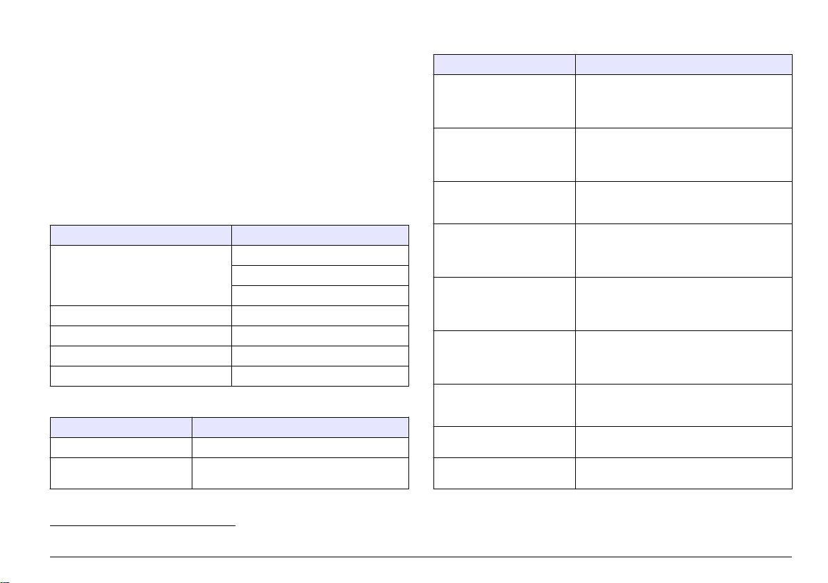
Table of contents
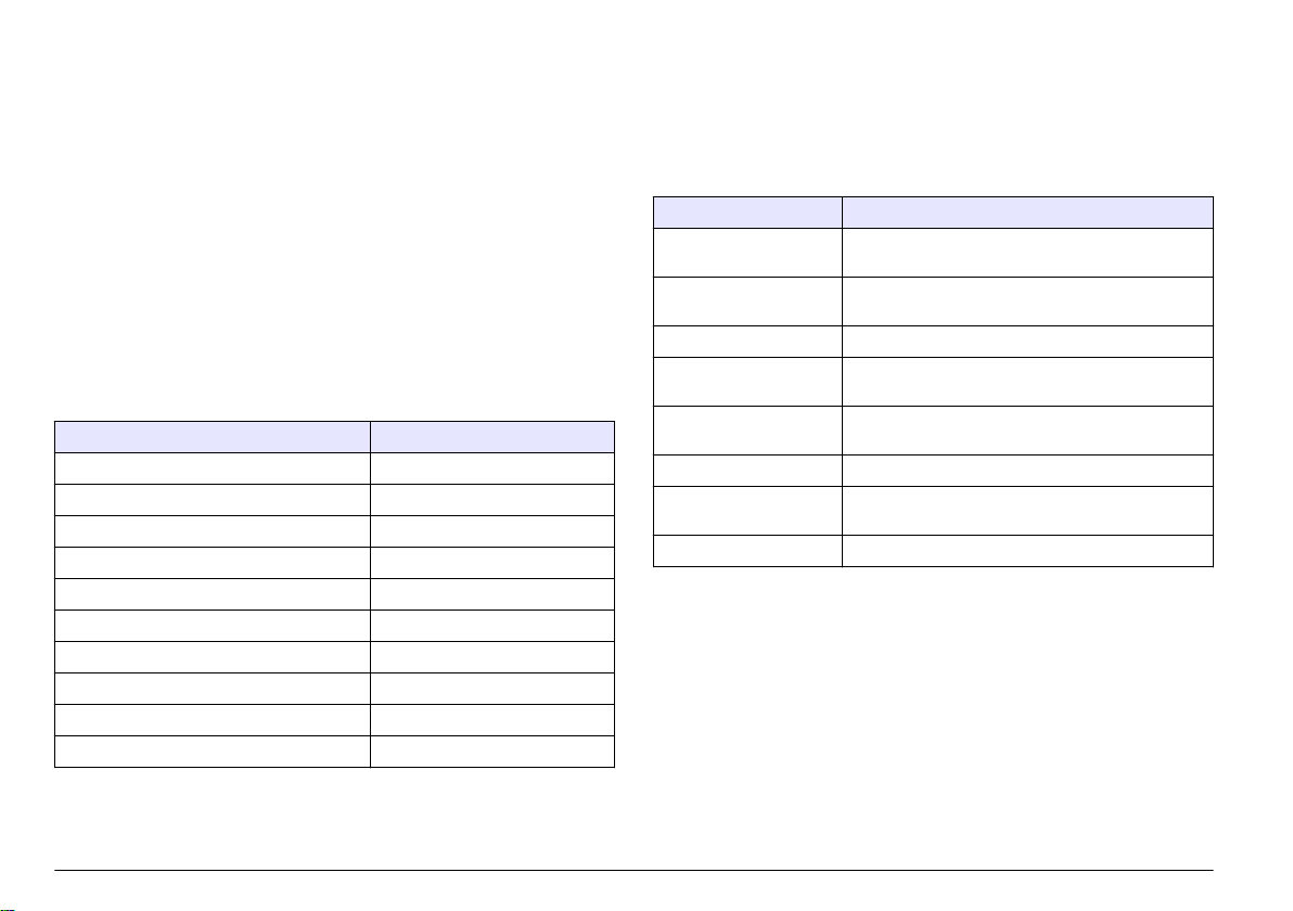
Specifications on page 3 Maintenance on page 15
General information on page 4 Troubleshooting on page 16
Installation on page 5 Replacement parts and accessories
on page 19
Operation on page 10
Specifications
Specifications are subject to change without notice.
Table 1 Module specifications
Specification Details
Measuring range Cell constant 0.01: 0.01–200 µS/cm
Cell constant 0.1: 0.1 µS–2 mS/cm
Cell constant 1: 1 µS–20 mS/cm
Response time 0.5 seconds
Repeatability/precision (0–20 µS/cm) ±0.1/0.1 µS/cm
Precision (20–200,000 µS/cm) ±0.5% of reading
Maximum cable length 91 m (299 ft)
Table 2 Sensor specifications
Specification Details
Temperature element PT100
Sensor cable 4 conductor (plus 2 shields); 5 m (16 ft), 10 m
(33 ft) or 20 m (66 ft); rated at 150 °C (302 °F)
Table 2 Sensor specifications (continued)
Specification Details
Wetted materials—8310 Black PSU body, stainless steel 316L internal
Wetted materials—8311 Black PSU body, stainless steel 316L internal
Wetted materials—8312 Black PSU body, graphite internal electrode,
Wetted materials—8315 Stainless steel 316L body, stainless steel 316L
Wetted materials—8316 Stainless steel 316L body, stainless steel 316L
Wetted materials—8317 Stainless steel 316L body, graphite internal
Wetted materials—8394 Stainless steel body, 316L electrode, PEEK® ,
Temperature/pressure limit—
8315, 8316, 8317 or 8394
Temperature/pressure limit—
8310, 8311 or 8312
electrode, stainless steel 316L external
electrode, PSU insulator and glass
polyester/IP65 connector
electrode, stainless steel 316L external
electrode, PSU insulator and glass
polyester/IP65 connector
graphite external electrode, PSU insulator and
glass polyester/IP65 connector
internal electrode, stainless steel 316L external
electrode, PES insulator, Viton® o-ring and
glass polyester/IP65 connector
internal electrode, stainless steel 316L external
electrode, PES insulator, Viton o-ring and glass
polyester/IP65 connector
electrode, graphite external electrode, PES
insulator, Viton o-ring and glass
polyester/IP65 connector
EPDM gasket and glass
polyester/IP65 connector
150 °C (302 °F) at 25 bar (362.5 psi)
1
125 °C (257 °F) at 10 bar (145 psi)
1
Other brands of mounting hardware and sanitary clamps may reduce the listed rating.
English 3
Page 4
General information
In no event will the manufacturer be liable for direct, indirect, special,
incidental or consequential damages resulting from any defect or
omission in this manual. The manufacturer reserves the right to make
changes in this manual and the products it describes at any time, without
notice or obligation. Revised editions are found on the manufacturer’s
website.
Safety information
N O T I C E
The manufacturer is not responsible for any damages due to misapplication or
misuse of this product including, without limitation, direct, incidental and
consequential damages, and disclaims such damages to the full extent permitted
under applicable law. The user is solely responsible to identify critical application
risks and install appropriate mechanisms to protect processes during a possible
equipment malfunction.
Please read this entire manual before unpacking, setting up or operating
this equipment. Pay attention to all danger and caution statements.
Failure to do so could result in serious injury to the operator or damage
to the equipment.
Make sure that the protection provided by this equipment is not impaired.
Do not use or install this equipment in any manner other than that
specified in this manual.
Use of hazard information
Indicates a potentially or imminently hazardous situation which, if not avoided, will
result in death or serious injury.
D A N G ER
N O T I C E
Indicates a situation which, if not avoided, may cause damage to the instrument.
Information that requires special emphasis.
Precautionary labels
Read all labels and tags attached to the instrument. Personal injury or
damage to the instrument could occur if not observed. A symbol on the
instrument is referenced in the manual with a precautionary statement.
This is the safety alert symbol. Obey all safety messages that follow
this symbol to avoid potential injury. If on the instrument, refer to the
instruction manual for operation or safety information.
This symbol indicates the presence of devices sensitive to Electrostatic Discharge (ESD) and indicates that care must be taken to
prevent damage with the equipment.
Electrical equipment marked with this symbol may not be disposed of
in European domestic or public disposal systems. Return old or endof-life equipment to the manufacturer for disposal at no charge to the
user.
Product overview
This sensor is designed to work with a controller for data collection and
operation. Multiple controllers can be used with this sensor.
The sensor is available in different styles. Refer to Figure 1.
W A R N IN G
Indicates a potentially or imminently hazardous situation which, if not avoided,
could result in death or serious injury.
Indicates a potentially hazardous situation that may result in minor or moderate
injury.
C A U T IO N
4 English
Page 5
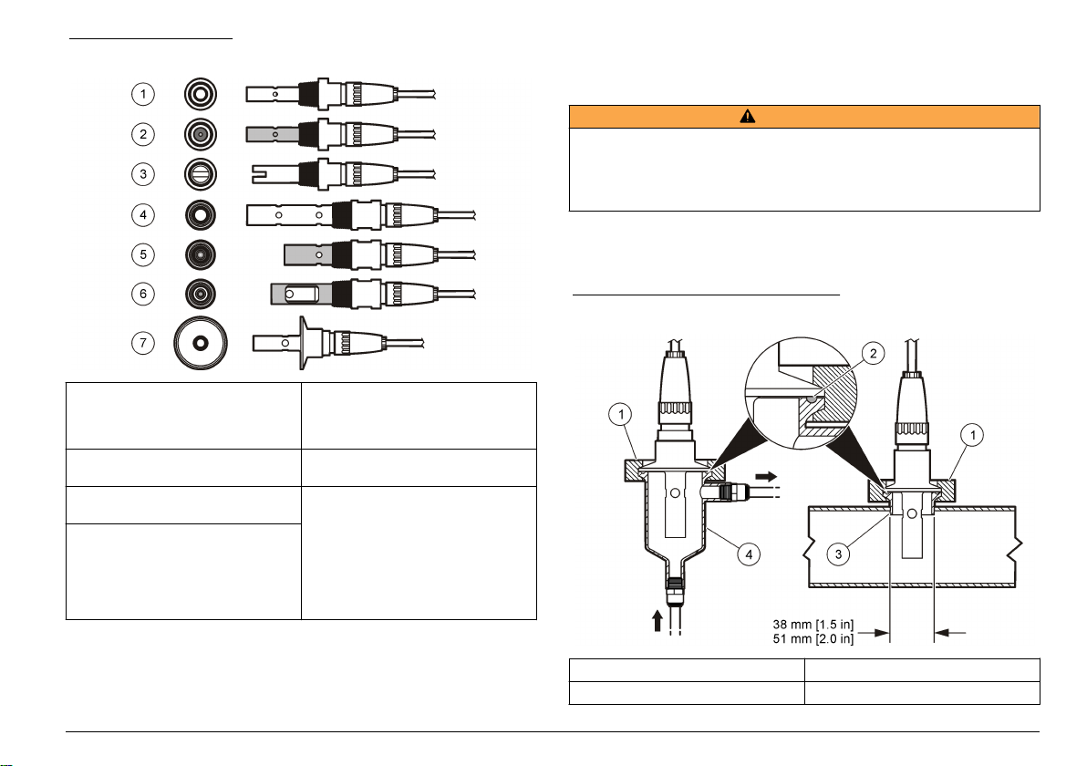
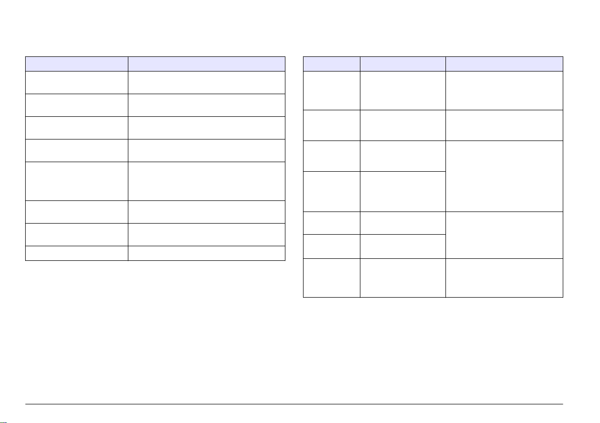
Figure 1 Sensor styles
Installation
Mounting
W A R N IN G
Personal injury hazard. Removal of a sensor from a pressurized vessel can be
dangerous. Installation and removal of these sensors should be done by
individuals trained in proper high pressure and temperature installation. Always
use industry approved hardware and safety procedures when dealing with high
pressure and/or temperature fluid transport systems.
For examples of sensors in different applications, refer to Figure 2 or
Figure 3. The sensor must be calibrated before use. Refer to Calibrate
the sensor on page 11.
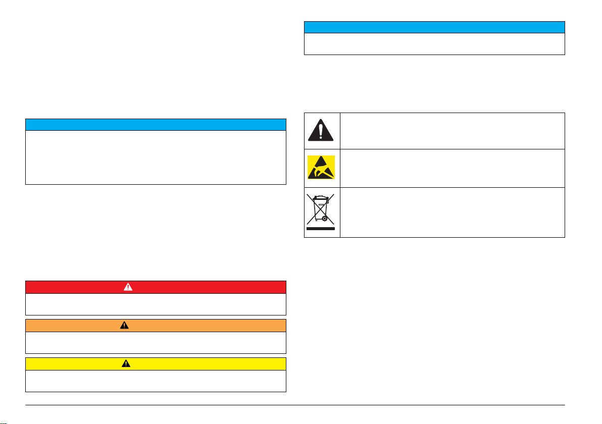
Figure 2 Sanitary mounting examples
1 8310, k = 0.01; applications include
drinking water, wastewater
treatement, chemical processes,
demineralized and softened water
2 8311, k = 0.1; same applications as
8310
3 8312, k = 1; same applications as
8310
4 8315, k = 0.01; applications include
pure water production monitoring
(ion exchangers and distillators)
and process water monitoring
(condensates, cleaning cycles and
heat exchangers)
5 8316, k = 0.1; same applications as
8315
6 8317, k = 1; same applications as
8315
7 8394, k = 0.01; sanitary style; 1.5-
or 2-in. diameter; applications
include ultrapure water monitoring
in pharmaceutical and food
industries and suitable for CIP-SIP
processes
1 Sanitary clamp 3 Ferrule (welded to pipe)
2 Gasket 4 Flow-thru chamber
English 5
Page 6
Figure 3 Mounting examples
1 Flow-thru T-mount, PVC, 3/4-in. NPT 2 Flow-thru T-mount, stainless steel, 1/4-in. NPT
6 English
Page 7
Connect the sensor to the module
W A R N IN G
Potential Electrocution Hazard. Always disconnect power to the
instrument when making electrical connections.
W A R N IN G
Electrocution Hazard. High voltage wiring for the controller is conducted behind
the high voltage barrier in the controller enclosure. The barrier must remain in
place except when installing modules, or when a qualified installation technician
is wiring for power, relays or analog and network cards.
Potential Instrument Damage. Delicate internal electronic components
can be damaged by static electricity, resulting in degraded
performance or eventual failure.
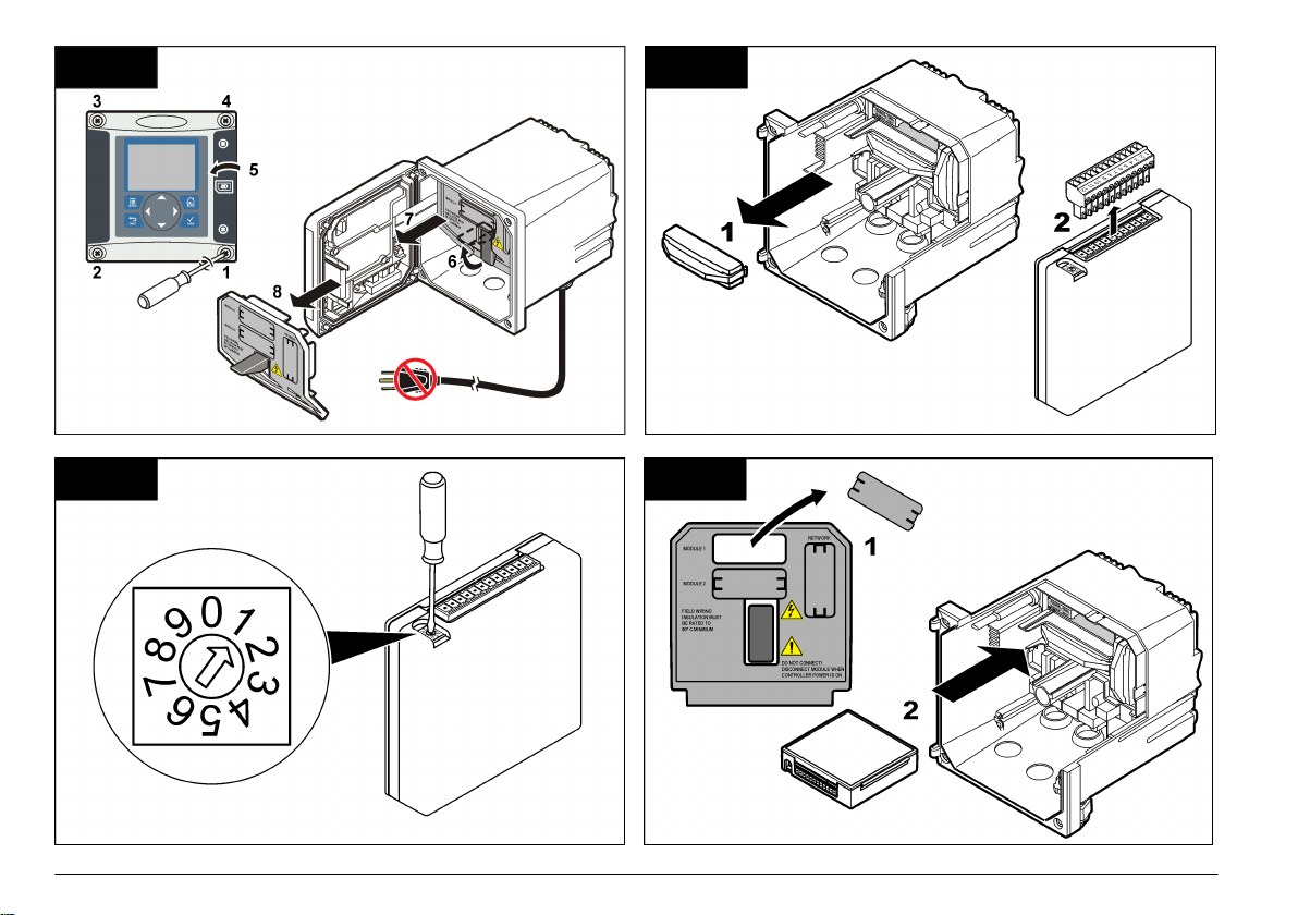
To install the module and connect the sensor, refer to the illustrated
steps on the following pages and Table 3. Be sure to connect the white
wire with the red tip from the sensor to the controller chassis.
Note: If the sensor cable is not long enough to reach the controller, an interconnect
cable and junction box are required to extend the distance.
N O T I C E
Table 3 Polymetron conductivity sensor wiring
Connector pin no. Signal Sensor wire
1 Out White
2 — —
3 Ground Black
4 — —
5 — —
6 — —
7 Temp – Black
8 — —
9 — —
10 Temp + Blue
11 In Red
12 — —
English 7
Page 8
1 2
3 4
8 English
Page 9

5 6
7 8
English 9
Page 10

Operation
User navigation
Refer to the controller documentation for keypad description and
navigation information.
Configure the sensor
Use the Configure menu to enter identification information for the sensor
and to change options for data handling and storage.
1. Push the MENU key and select Sensor Setup, [Select Sensor],
Configure.
2. Use the arrow keys to select an option and push ENTER. To enter
numbers, characters or punctuation, push and hold the UP or DOWN
arrow keys. Push the RIGHT arrow key to advance to the next
space.
Option Description
EDIT NAME Changes the name that corresponds to the sensor on
the top of the measure screen. The name is limited to
10 characters in any combination of letters, numbers,
spaces or punctuation.
SENSOR S/N Allows the user to enter the serial number of the
sensor, limited to 16 characters in any combination of
letters, numbers, spaces or punctuation.
SELECT MEASURE Changes the measured parameter to conductivity
(default), TDS (total dissolved solids), salinity or
resistivity. When the parameter is changed, all other
configured settings are reset to the default values.
DISPLAY FORMAT Changes the number of decimal places that are
shown on the measure screen to auto (default),
X.XXX, XX.XX, XXX.X or XXXX. When set to auto, the
number of decimal places changes automatically with
changes in the measured value.
MEAS UNITS Changes the units for the selected measurement—
conductivity: µS/cm (default), mS/cm, µS/m, mS/m or
S/m.
Option Description
TEMP UNITS Sets the temperature units to °C (default) or °F.
T-COMPENSATION Adds a temperature-dependent correction to the
CELL CONSTANT Sets the cell constant range to 0.05, 0.5, 1.0 (default),
CABLE LENGTH Sets the actual length of the sensor cable to improve
TEMP ELEMENT Sets the temperature element for automatic
FILTER Sets a time constant to increase signal stability. The
measured value—linear (default: 2.0%/°C, 25 °C),
ammonia, temp table (enter x,y points in ascending
order), none, natural water or pure water. For special
applications, a user-defined linear compensation can
be entered (0–4%/°C, 0–200 °C). Natural water
compensation is not available for TDS.
5.0, 10.0, 0.01 Polymetron, 0.1 Polymetron, or
1.0 Polymetron. After the range is selected, the user
can enter the certified K value from the label on the
sensor cable. When the certified K value is entered,
the calibration curve is defined.
measurement accuracy (default: 20 ft (Polymetron
sensors default: 5 ft)).
temperature compensation to PT100 or
PT1000 (default). After selection, the user should
enter the certified T-factor from the label on the sensor
cable for best accuracy. If no element is used, the
type can be set to manual and a value for temperature
compensation can be entered (manual default: 25 °C).
Note: If a sensor with a PT100 or PT1000 element is
set to manual and the sensor is replaced or the sensor
days are reset, the TEMP ELEMENT automatically
changes to the default setting.
time constant calculates the average value during a
specified time—0 (no effect, default) to 60 seconds
(average of signal value for 60 seconds). The filter
increases the time for the sensor signal to respond to
actual changes in the process.
10 English
Page 11

Option Description
LOG SETUP Sets the time interval for data storage in the data log
—5, 30 seconds, 1, 2, 5, 10, 15 (default), 30,
60 minutes.
RESET DEFAULTS Sets the configuration menu to the default settings. All
user-defined settings are lost.
Adjust the T-factor for non-standard cable lengths
When the sensor cable is extended or shortened from the standard 6 m
(20 ft), the resistance of the cable changes. This change reduces the
accuracy of temperature measurements. To correct for this difference,
calculate a new T-factor.
Note: This procedure applies only to sensors with a PT1000 temperature element.
Sensors with a PT100 temperature element are less accurate.
1. Measure the temperature of a solution with the sensor and with an
independent, reliable instrument such as a thermometer.
2. Record the difference between the temperature measured from the
sensor and from the independent source (actual).
For example, if the actual temperature is 50 °C and the sensor
reading is 53 °C, the difference is 3 °C.
3. Multiply this difference by 3.85 to get an adjustment value.
Example: 3 x 3.85 = 11.55.
4. Calculate a new T-factor:
• Sensor temperature > actual—add the adjustment value to the Tfactor on the sensor cable
• Sensor temperature < actual—subtract the adjustment value from
the T-factor on the sensor cable
5. Enter the new T-factor in the Configure, Temp Element menu.
Calibrate the sensor
About sensor calibration
During calibration, data is not sent to the datalog. Thus, the datalog can
have areas where the data is intermittent.
Zero calibration procedure
Use the zero calibration procedure to define the unique zero point of the
conductivity sensor. The zero point must be defined before the sensor is
calibrated for the first time with a reference solution or process sample.
1. Remove the sensor from the process. Wipe the sensor with a clean
towel or use compressed air to make sure the sensor is clean and
dry.
2. Push the MENU key and select Sensor Setup, [Select Sensor],
Calibrate.
3. Push ENTER to select Zero Cal.
4. If the passcode is enabled in the security menu for the controller,
enter the passcode.
5. Select the option for the output signal during calibration:
Option Description
Active The instrument sends the current measured output value during
the calibration procedure.
Hold The sensor output value is held at the current measured value
during the calibration procedure.
Transfer A preset output value is sent during calibration. Refer to the
controller user manual to change the preset value.
6. Hold the dry sensor in the air and push ENTER.
7. Review the calibration result:
• Pass—the zero point is set.
• Fail—the value is outside of accepted limits. Make sure the sensor
is dry and repeat the zero calibration procedure. Make sure that
the cause is not the digital extension cable or a lot of electronic
noise.
8. If the calibration passed, push ENTER to continue.
9. For the sc100 controller, go to step 12.
10. If the option for operator ID is set to Yes in the Calibration Options
menu, enter an operator ID. Refer to Change calibration options
on page 14.
English
11
Page 12
11. On the New Sensor screen, select whether the sensor is new:
Option Description
Yes The sensor was not calibrated previously with this controller. The
days of operation and previous calibration curves for the sensor are
reset.
No The sensor was calibrated previously with this controller.
12. Proceed to the calibration with a reference solution or process
sample.
Calibration with a reference solution
Calibration adjusts the sensor reading to match the value of a reference
solution. Use a reference solution that is at the same value or higher
than the expected measurement readings.
Note: If the sensor is being calibrated for the first time, be sure to complete the
zero calibration first.
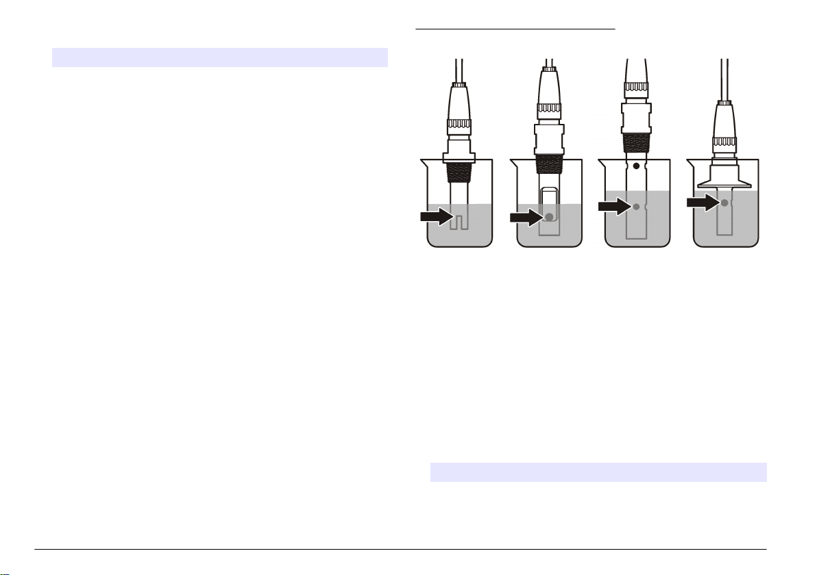
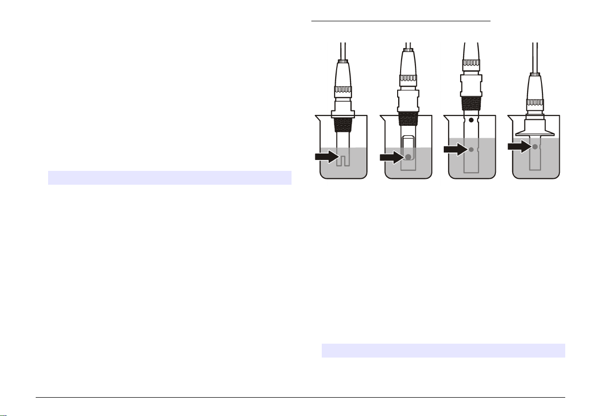
Figure 4 Sensor in reference solution
1. Thoroughly rinse the clean sensor in deionized water.
2. Put the sensor in the reference solution. Support the sensor so that it
does not touch the container. Make sure that the sensing area is fully
immersed in the solution (Figure 4). Stir the sensor to remove
bubbles.
12 English
3. Wait for the sensor and solution temperature to equalize. This can
take 30 minutes or more if the temperature difference between the
process and reference solution is significant.
4. Push the MENU key and select Sensor Setup, [Select Sensor],
Calibrate.
5. Select the calibration for the specified parameter and push ENTER:
• Conductivity—Cond Cal
• TDS—TDS Cal
• Salinity—Cond Cal
• Concentration—Conc Cal or Cond Cal
6. If the passcode is enabled in the security menu for the controller,
enter the passcode.
7. Select the option for the output signal during calibration:
Option Description
Active The instrument sends the current measured output value during
the calibration procedure.
Page 13

Option Description
Hold The sensor output value is held at the current measured value
during the calibration procedure.
Transfer A preset output value is sent during calibration. Refer to the
controller user manual to change the preset value.
8. With the sensor in the reference solution, push ENTER.
9. Enter the reference temperature of the reference solution and push
ENTER.
10. Enter the slope of the reference solution and push ENTER.
11. Wait for the value to stabilize and push ENTER.
Note: The screen may advance to the next step automatically.
12. Use the arrow keys to enter the value of the reference solution and
push ENTER.
13. Review the calibration result:
• Passed—the sensor is calibrated and ready to measure samples.
The slope and/or offset values are shown.
• Failed—the calibration slope or offset is outside of accepted limits.
Repeat the calibration with fresh reference solutions. Refer to
Maintenance on page 15 and Troubleshooting on page 16 for
more information.
14. If the calibration passed, push ENTER to continue.
15. If the option for operator ID is set to Yes in the Calibration Options
menu, enter an operator ID. Refer to Change calibration options
on page 14.
16. On the New Sensor screen, select whether the sensor is new:
Option Description
Yes The sensor was not calibrated previously with this controller. The
days of operation and previous calibration curves for the sensor are
reset.
No The sensor was calibrated previously with this controller.
17. Return the sensor to the process and push ENTER.
The output signal returns to the active state and the measured
sample value is shown on the measure screen.
Note: If the output mode is set to hold or transfer, select the delay time when
the outputs return to the active state.
Calibration with the process sample
The sensor can remain in the process sample, or a portion of the
process sample can be removed for calibration.
1. Push the MENU key and select Sensor Setup, [Select Sensor],
Calibrate.
2. Select the calibration for the specified parameter and push ENTER:
• Conductivity—Cond Cal
• TDS—TDS Cal
• Salinity—Cond Cal
• Concentration—Conc Cal or Cond Cal
3. If the passcode is enabled in the security menu for the controller,
enter the passcode.
4. Select the option for the output signal during calibration:
Option Description
Active The instrument sends the current measured output value during
Hold The sensor output value is held at the current measured value
Transfer A preset output value is sent during calibration. Refer to the
5. With the sensor in the process sample, push ENTER.
The measured value is shown.
6. Wait for the value to stabilize and push ENTER.
7. Use the arrow keys to enter the value of the process sample and
push ENTER.
the calibration procedure.
during the calibration procedure.
controller user manual to change the preset value.
English
13
Page 14

8. Review the calibration result:
• Passed—the sensor is calibrated and ready to measure samples.
The slope and/or offset values are shown.
• Failed—the calibration slope or offset is outside of accepted limits.
Repeat the calibration with fresh reference solutions. Refer to
Maintenance on page 15 and Troubleshooting on page 16 for
more information.
9. If the calibration passed, push ENTER to continue.
10. If the option for operator ID is set to Yes in the Calibration Options
menu, enter an operator ID. Refer to Change calibration options
on page 14.
11. On the New Sensor screen, select whether the sensor is new:
Option Description
Yes The sensor was not calibrated previously with this controller. The
days of operation and previous calibration curves for the sensor are
reset.
No The sensor was calibrated previously with this controller.
12. Return the sensor to the process and push ENTER.
The output signal returns to the active state and the measured
sample value is shown on the measure screen.
Note: If the output mode is set to hold or transfer, select the delay time when
the outputs return to the active state.
Temperature calibration
The instrument is calibrated at the factory for accurate temperature
measurement. The temperature can be calibrated to increase accuracy.
1. Put the sensor in a container of water.
2. Measure the temperature of the water with an accurate thermometer
or independent instrument.
3. Push the MENU key and select Sensor Setup, [Select Sensor],
Calibrate.
4. Select 1 PT Temp Cal and push ENTER.
5. Wait for the value to stabilize and push ENTER.
6. Enter the exact value and push ENTER.
7. Return the sensor to the process and push ENTER.
Exit calibration procedure
If the BACK key is pushed during a calibration, the user can exit the
calibration.
1. Push the BACK key during a calibration. Three options are shown:
Option Description
QUIT CAL Stop the calibration. A new calibration must start from the
beginning.
BACK TO CAL Return to the calibration.
LEAVE CAL Exit the calibration temporarily. Access to other menus is
allowed. A calibration for a second sensor (if present) can
be started. To return to the calibration, push the MENU key
and select Sensor Setup, [Select Sensor].
2. Use the arrow keys to select one of the options and push ENTER.
Change calibration options
The user can set a reminder or include an operator ID with calibration
data from the CAL OPTIONS menu.
1. Push the MENU key and select Sensor Setup, [Select Sensor],
Calibrate, Cal Options.
2. Use the arrow keys to select an option and push ENTER.
Option Description
CAL REMINDER Sets a reminder for the next calibration in days, months or
years—Off (default), 1 day, 7, 30, 60, or 90 days, 6 or
9 months, 1 or 2 years
OP ID on CAL Includes an operator ID with calibration data—Yes or No
(default). The ID is entered during the calibration.
14 English
Page 15
Reset calibration options
The calibration options can be reset to the factory default options.
1. Push the MENU key and select Sensor Setup, [Select Sensor],
Calibrate, Reset Default Cal.
2. If the passcode is enabled in the security menu for the controller,
enter the passcode.
3. Push ENTER. The Reset Cal? screen is shown.
4. Push ENTER. All calibration options are set to the default values.
5. If the option for operator ID is set to Yes in the Calibration Options
menu, enter an operator ID. Refer to Change calibration options
on page 14.
6. On the New Sensor screen, select whether the sensor is new:
Option Description
Yes The sensor was not calibrated previously with this controller. The
days of operation and previous calibration curves for the sensor are
reset.
No The sensor was calibrated previously with this controller.
7. Push the BACK key to return to the measure screen.
Modbus registers
A list of Modbus registers is available for network communication. Refer
to the manufacturer's website for more information.
Maintenance
D A N G ER
Multiple hazards. Only qualified personnel must conduct the tasks
described in this section of the document.
Clean the sensor
W A R N IN G
Chemical exposure hazard. Obey laboratory safety procedures and
wear all of the personal protective equipment appropriate to the
chemicals that are handled. Refer to the current safety data sheets
(MSDS/SDS) for safety protocols.
W A R N IN G
Personal injury hazard. Removal of a sensor from a pressurized vessel can be
dangerous. Installation and removal of these sensors should be done by
individuals trained in proper high pressure and temperature installation. Always
use industry approved hardware and safety procedures when dealing with high
pressure and/or temperature fluid transport systems.
Pre-requisite: Prepare a mild soap solution with warm water and
dishwashing detergent, Borax hand soap or a similar soap.
Examine the sensor periodically for debris and deposits. Clean the
sensor when there is a buildup of deposits or when performance has
degraded.
1. Use a clean, soft cloth to remove loose debris from the end of the
sensor. Rinse the sensor with clean, warm water.
2. Soak the sensor for 2 to 3 minutes in the soap solution.
3. Use a soft bristle brush to scrub the entire measuring end of the
sensor.
4. If debris remains, soak the measuring end of the sensor in a dilute
acid solution such as < 5% HCl for a maximum of 5 minutes.
5. Rinse the sensor with water and then return to the soap solution for
2 to 3 minutes.
6. Rinse the sensor with clean water.
Always calibrate the sensor after maintenance procedures are done.
English
15
Page 16
Troubleshooting
Intermittent data
During calibration, data is not sent to the datalog. Thus, the datalog can
have areas where the data is intermittent.
Test the conductivity sensor
If a calibration fails, first complete the maintenance procedures in
Maintenance on page 15.
1. Disconnect the sensor wires.
2. Use an ohmmeter to test the resistance between the sensor wires as
shown in Table 4.
Note: Be sure that the ohmmeter is set to its highest range for all infinite (open
circuit) resistance readings.
Table 4 Conductivity resistance measurements
Measurement points Resistance
Between blue and white wires 1089–1106 ohms at 23–27 °C
Between red wire and sensor body Less than 5 ohms
Between black wire and inner electrode Less than 5 ohms
Between black and red wires Infinite (open circuit)
Between black and white wires Infinite (open circuit)
Between red and white wires Infinite (open circuit)
Between red and inner shield wires Infinite (open circuit)
Between black and inner shield wires Infinite (open circuit)
Between white and inner shield wires Infinite (open circuit)
Between outer and inner shield wires Infinite (open circuit)
Sensor diagnostic and test menu
The sensor diagnostic and test menu shows current and historical
information about the instrument. Refer to Table 5. To access the sensor
diagnostic and test menu, push the MENU key and select Sensor Setup,
[Select Sensor], DIAG/TEST.
Table 5 Sensor DIAG/TEST menu
Option Description
SENSOR INFORMATION Shows the name and serial number that was entered
by the user.
CARD INFORMATION Shows the version and the serial number for the
sensor module.
CAL DAYS Shows the number of days since the last calibration.
CAL HISTORY Shows a list of the calibrations and the details for
each calibration.
RESET CAL HISTORY Service use only. Resets the calibration history for
the sensor. All previous calibration data is lost.
SENSOR SIGNALS Shows the current sensor signal and span in µS/cm.
SENSOR DAYS Shows the number of days that the sensor has been
in operation.
RESET SENSOR DAYS Resets the Sensor Days counter.
Error list
When an error occurs, the reading on the measurement screen flashes
and all outputs are held when specified in the controller menu. To show
If one or more of the measurements is incorrect, call technical support.
Supply technical support with the serial number of the sensor and the
resistance values measured.
16
English
Page 17

the sensor errors, press the MENU key and select Sensor Diag, [Select
Sensor], Error List. A list of possible errors is shown in Table 6.
Table 6 Error list for conductivity sensors
Error Description Resolution
MEAS TOO
HIGH
MEAS TOO
LOW
ZERO TOO
HIGH
ZERO TOO
LOW
TEMP TOO
HIGH
TEMP TOO
LOW
ADC
FAILURE
The measured value is >
2,000,000 µS/cm,
1,000,000 ppm or
20,000 ppt
The measured value is <
0 µS/cm, 0 ppm or 0 ppt
The zero calibration value is
> 500,000 counts
The zero calibration value is
< –500,000 counts
The measured temperature
is > 130 °C
The measured temperature
is < –10 °C
The analog to digital
conversion failed
Make sure that the sensor is
configured for the correct cell
constant.
Make sure that the sensor is
configured for the correct cell
constant.
Make sure that the sensor is held
in air during zero calibration and is
not located near radio frequency or
electromagnetic interference.
Make sure that the cable is
shielded by metal conduit.
Make sure that the sensor is
configured for the correct
temperature element. Refer to
Test the conductivity sensor
on page 16.
Make sure that the sensor module
is fully inserted into the controller
connector. Replace the sensor
module.
Table 6 Error list for conductivity sensors (continued)
Error Description Resolution
SENSOR
MISSING
SENS OUT
RANGE
The sensor is missing or
disconnected
The sensor signal is outside
of the accepted limits for
the cell constant that is
used (0.01 and 0.05:
100 µS/cm; 0.5:
1000 µS/cm; 1:
2000 µS/cm; 5:
10,000 µS/cm; 10:
200,000 µS/cm)
Examine the wiring and
connections for the sensor and for
the module. Make sure that the
terminal block is fully inserted into
the module.
Make sure that the sensor is
configured for the correct cell
constant.
Warning list for sensors
A warning does not affect the operation of menus, relays and outputs. A
warning icon flashes and a message is shown on the bottom of the
measurement screen. To show the sensor warnings, press the MENU
key and select Sensor Diag, [Select Sensor], Warning List. A list of
possible warnings is shown in Table 7.
Table 7 Warning list for conductivity sensors
Warning Description Resolution
ZERO TOO HIGH The zero calibration value
is >300,000 counts
ZERO TOO LOW The zero calibration value
is < –300,000 counts
TEMP TOO HIGH The measured temperature
is > 100 °C
TEMP TOO LOW The measured temperature
is < 0 °C
Make sure that the sensor is
held in air during zero
calibration and is not located
near radio frequency or
electromagnetic interference.
Make sure that the cable is
shielded by metal conduit.
Make sure that the sensor is
configured for the correct
temperature element.
English 17
Page 18

Table 7 Warning list for conductivity sensors (continued)
Warning Description Resolution
CAL OVERDUE The Cal Reminder time
NOT
CALIBRATED
REPLACE
SENSOR
CAL IN
PROGRESS
OUTPUTS ON
HOLD
WRONG LINEARTCThe user-defined linear
WRONG TC
TABLE
has expired
The sensor has not been
calibrated
The sensor has been in
operation > 365 days
A calibration was started
but not completed
During calibration, the
outputs were set to hold for
a selected time.
temperature compensation
is out of range
The user-defined
temperature compensation
table is out of range
Calibrate the sensor.
Calibrate the sensor.
Calibrate the sensor with a
reference solution and reset
the sensor days. Refer to
Sensor diagnostic and test
menu on page 16. If the
calibration fails, call technical
support.
Return to calibration.
The outputs will become active
after the selected time period.
The value must be between
0 and 4%/°C; 0 to 200 °C.
The temperature is above or
below the temperature range
defined by the table.
Event list for sensors
The event list shows current activities such as configuration changes,
alarms, warning conditions, etc. To show the events, press the MENU
key and select Sensor Diag, [Select Sensor], Event List. A list of possible
events is shown in Table 8. Previous events are recorded in the event
log, which can be downloaded from the controller. Refer to the controller
documentation for data retrieval options.
Table 8 Event list for conductivity sensors
Event Description
CAL READY The sensor is ready for calibration
CAL OK The current calibration is good
TIME EXPIRED The stabilization time during calibration expired
CAL FAIL The calibration failed
CAL HIGH The calibration value is above the upper limit
K OUTRANGE The cell constant K is out of range for the current
calibration
UNSTABLE The reading during calibration was unstable
CHANGE IN CONFIG float The configuration was changed—floating point type
CHANGE IN CONFIG text The configuration was changed—text type
CHANGE IN CONFIG int The configuration was changed—integer value type
RESET CONFIG The configuration was reset to the default options
POWER ON EVENT The power was turned on
ADC FAILURE The ADC conversion failed (hardware failure)
FLASH ERASE The external serial flash memory erase occurred
TEMPERATURE The temperature is out of range (-20 to 200 °C)
SAMPLE CAL START Start of calibration for conductivity
SAMPLE CAL END End of calibration for conductivity
ZERO CAL START Start of zero calibration
ZERO CAL END End of zero calibration
18 English
Page 19

Replacement parts and accessories
Note: Product and Article numbers may vary for some selling regions. Contact the
appropriate distributor or refer to the company website for contact information.
Consumables
Description Quantity Item no.
Conductivity reference solution,
100–1000 µS/cm
Conductivity reference solution,
1000–2000 µS/cm
Conductivity reference solution,
2000–150,000 µS/cm
Conductivity reference solution,
200,000–300,000 µS/cm
Parts and accessories
Description Item no.
Cable, 5 m (16 ft) 08319=A=0005
Cable, 10 m (33 ft) 08319=A=0010
Cable, 20 m (66 ft) 08319=A=0020
Flow-thru chamber, 6 mm (¼ in.) NPT threading 08318=A=0001
Flow-thru chamber, 19 mm (¾ in.) NPT threading 08313=A=0001
Gasket, EDPM, 38 mm (1.5 in.) 429=500=380
Gasket, EDPM, 51 mm (2 in.) 429=500=510
Mounting kit with EPDM gasket, clamp and stainless steel
ferrule (h=13 mm), 38 mm (1.5 in.) internal diameter,
50.5 mm (1.99 in.) external diameter
Mounting kit with EPDM gasket, clamp and stainless steel
ferrule (h=13 mm), 51 mm (2 in.) internal diameter, 64 mm
(2.52 in.) external diameter
1 L 25M3A2000-119
1 L 25M3A2050-119
1 L 25M3A2100-119
1 L 25M3A2200-119
08394=A=0380
08394=A=0510
Parts and accessories (continued)
Description Item no.
Mounting kit with EPDM gasket, clamp and stainless steel
flow-thru chamber, 38 mm (1.5 in.) internal diameter,
50.5 mm (1.99 in.) external diameter
Mounting kit with EPDM gasket, clamp and stainless steel
flow-thru chamber, 51 mm (2 in.) internal diameter, 64 mm
(2.52 in.) external diameter
Certificate, standard test certificate states the real value of
the cell constant at ± 2% according to ISO 7888, ASTM
D5391; 50.5 mm (1.99 in.) external diameter
Certificate, optional conformity certificate (FDA materials,
stainless steel EN 10204 3.1 B, roughness coefficient <
0.4 µm); 50.5 mm (1.99 in.) external diameter
Certificate, standard test certificate states the real value of
the cell constant at ± 2% according to ISO 7888, ASTM
D5391; 64 mm (2.52 in.) external diameter
Certificate, optional conformity certificate (FDA materials,
stainless steel EN 10204 3.1 B, roughness coefficient <
0.4 µm); 64 mm (2.52 in.) external diameter
08394=A=8150
08394=A=8200
08394=A=1500
08394=A=1511
08394=A=2000
08394=A=2011
English 19
Page 20

Table des matières
Caractéristiques à la page 20 Maintenance à la page 32
Généralités à la page 21 Dépannage à la page 33
Installation à la page 22 Pièces et accessoires de rechange
à la page 36
Fonctionnement à la page 27
Caractéristiques
Les caractéristiques techniques peuvent être modifiées sans préavis.
Tableau 1 Caractéristiques du module
Caractéristique Détails
Plage de mesures Constante de cellule 0,01 :
0,01–200 µS/cm
Constante de cellule 0,1 : 0,1 µS–2 mS/cm
Constante de cellule 1 : 1 µS 20 mS/cm
Temps de réponse 0.5 seconde
Répétabilité/précision (0–20 µS/cm) ±0,1/0,1 µS/cm
Précision (20–200,000 µS/cm) ± 0,5 % de la mesure
Longueur de câble maximum 91 m (299 ft)
Tableau 2 Caractéristiques techniques des capteurs
Caractéristique Détails
Elément de température PT100
Câble du capteur 4 conducteurs (plus 2 blindages) ; 5 m (16 ft),
10 m (33 ft) ou 20 m (66 ft) ; température
nominale de 150 °C (302 °F)
Tableau 2 Caractéristiques techniques des capteurs (suite)
Caractéristique Détails
Matériaux immergés—8310 Corps PSU noir, électrode interne 316L en
Matériaux immergés—8311 Corps PSU noir, électrode interne 316L en
Matériaux immergés—8312 Corps PSU noir, électrode interne en graphite,
Matériaux immergés—8315 Corps 316L en acier inoxydable, électrode
Matériaux immergés—8316 Corps 316L en acier inoxydable, électrode
Matériaux immergés—8317 Corps 316L en acier inoxydable, électrode
Matériaux immergés—8394 Corps en acier inoxydable, électrode 316L,
Limite de température/pression
—8315, 8316, 8317 ou 8394
Limite de température/pression
—8310, 8311 ou 8312
acier inoxydable, électrode externe 316L en
acier inoxydable, isolateur de bloc
d'alimentation et connecteur polyester/IP65
acier inoxydable, électrode externe 316L en
acier inoxydable, isolateur de bloc
d'alimentation et connecteur polyester/IP65
électrode externe en graphite, isolateur de bloc
d'alimentation et connecteur polyester/IP65
interne 316L en acier inoxydable, électrode
externe 316L en acier inoxydable, isolateur en
polyéthersulfone, joint torique Viton® et
connecteur en verre polyester/IP65
interne 316L en acier inoxydable, électrode
externe 316L en acier inoxydable, isolateur en
PES, joint torique Viton et connecteur en verre
polyester/IP65
interne en graphite, électrode externe en
graphite, isolateur en PES, joint torique Viton et
connecteur en verre polyester/IP65
PEEK®, joint EPDM et connecteur en verre
polyester/IP65
150 °C (302 °F) à 25 bar (362,5 psi)
1
125 °C (257 °F) à 10 bar (145 psi)
1
D'autres marques de fixations et de brides sanitaires peuvent réduire les valeurs nominales mentionnées.
20 Français
Page 21

Généralités
En aucun cas le constructeur ne saurait être responsable des
dommages directs, indirects, spéciaux, accessoires ou consécutifs
résultant d'un défaut ou d'une omission dans ce manuel. Le constructeur
se réserve le droit d'apporter des modifications à ce manuel et aux
produits décrits à tout moment, sans avertissement ni obligation. Les
éditions révisées se trouvent sur le site Internet du fabricant.
Consignes de sécurité
A V I S
Le fabricant décline toute responsabilité quant aux dégâts liés à une application
ou un usage inappropriés de ce produit, y compris, sans toutefois s'y limiter, des
dommages directs ou indirects, ainsi que des dommages consécutifs, et rejette
toute responsabilité quant à ces dommages dans la mesure où la loi applicable le
permet. L'utilisateur est seul responsable de la vérification des risques
d'application critiques et de la mise en place de mécanismes de protection des
processus en cas de défaillance de l'équipement.
Veuillez lire l'ensemble du manuel avant le déballage, la configuration ou
la mise en fonctionnement de cet appareil. Respectez toutes les
déclarations de prudence et d'attention. Le non-respect de cette
procédure peut conduire à des blessures graves de l'opérateur ou à des
dégâts sur le matériel.
Assurez-vous que la protection fournie avec cet appareil n'est pas
défaillante. N'utilisez ni n'installez cet appareil d'une façon différente de
celle décrite dans ce manuel.
Interprétation des indications de risques
Indique une situation de danger potentiel ou imminent qui, si elle n'est pas évitée,
entraîne des blessures graves, voire mortelles.
A V E R TI SS EM EN T
Indique une situation de danger potentiel ou imminent qui, si elle n'est pas évitée,
peut entraîner des blessures graves, voire mortelles.
D A N G ER
A T T E NT IO N
Indique une situation de danger potentiel qui peut entraîner des blessures
mineures ou légères.
Indique une situation qui, si elle n'est pas évitée, peut occasionner
l'endommagement du matériel. Informations nécessitant une attention
particulière.
A V I S
Etiquettes de mise en garde
Lisez toutes les informations et toutes les étiquettes apposées sur
l’appareil. Des personnes peuvent se blesser et le matériel peut être
endommagé si ces instructions ne sont pas respectées. Un symbole sur
l'appareil est référencé dans le manuel et accompagné d'une déclaration
de mise en garde.
Ceci est le symbole d'alerte de sécurité. Se conformer à tous les
messages de sécurité qui suivent ce symbole afin d'éviter tout risque
de blessure. S'ils sont apposés sur l'appareil, se référer au manuel
d'utilisation pour connaître le fonctionnement ou les informations de
sécurité.
Ce symbole indique la présence d'appareils sensibles aux décharges
électrostatiques et indique que des précautions doivent être prises
afin d'éviter d'endommager l'équipement.
Le matériel électrique portant ce symbole ne doit pas être mis au
rebut dans les réseaux domestiques ou publics européens.
Retournez le matériel usé ou en fin de vie au fabricant pour une mise
au rebut sans frais pour l'utilisateur.
Présentation du produit
Ce capteur est conçu pour fonctionner avec un contrôleur assurant la
collecte de données et le fonctionnement. Il est possible d'utiliser
plusieurs contrôleurs avec ce capteur.
Le capteur est disponible en différents types. Reportez-vous à la
Figure 1.
Français
21
Page 22

Figure 1 Types de capteur
Installation
Installation
1 8310, k = 0,01 ; les applications
sont l'eau potable, le traitement des
eaux usées, les processus
chimiques, l'eau déminéralisée et
adoucie
2 8311, k = 0,1 ; mêmes applications
que le type 8310
3 8312, k = 1 ; mêmes applications
que le type 8310
4 8315, k = 0,01 ; les applications
sont la surveillance de la production
d'eau pure (échangeurs d'ions et
distillateurs) et la surveillance de
l'eau de traitement (condensats,
cycles de nettoyage et échangeurs
de chaleur)
5 8316, k = 0,1 ; mêmes applications
que le type 8315
6 8317, k = 1 ; mêmes applications
que le type 8315
7 8394, k = 0,01 ; type sanitaire ;
diamètre de 1,5 ou 2 po ; les
applications sont la surveillance
d'eau ultrapure dans les industries
pharmaceutiques et
agroalimentaires ; compatibilité
avec les processus de nettoyage et
de stérilisation en place (NEP/SEP)
A V E R TI SS EM EN T
Risque de blessures. Le retrait d'un capteur d'une enceinte pressurisée peut
s'avérer dangereux. La pose et la dépose de ces capteurs doit être effectuée par
des personnes formées à l'installation correcte dans des situations de haute
pression et de température élevée. Utilisez toujours les procédures de sécurité et
du matériel homologués par le secteur lors de la manipulation de systèmes de
transport de fluides sous haute pression et/ou à température élevée.
Pour obtenir des exemples d'application des capteurs, reportez-vous à
la Figure 2 ou à la Figure 3. Le capteur doit être étalonné avant usage.
Voir Étalonnage du capteur à la page 28.
Figure 2 Exemples de montage sanitaire
22 Français
1 Elément de fixation sanitaire 3 Virole (soudée à la canalisation)
2 Joint 4 Chambre de circulation
Page 23

Figure 3 Exemples de montage
1 Fixation en T de circulation, PVC, 3/4 po NPT 2 Fixation en T de circulation, acier inoxydable, 1/4 po NPT
Français 23
Page 24

Branchement du capteur au module
A V E R TI SS EM EN T
Risque potentiel d'électrocution. Coupez systématiquement
l'alimentation de l'appareil lors de branchements électriques.
A V E R TI SS EM EN T
Risque d'électrocution. Le câblage à haute tension du transmetteur est effectué
derrière l'écran de protection à haute tension du boîtier du transmetteur. L'écran
de protection doit rester en place, sauf lors de l'installation de modules ou
l'installation par un technicien qualifié du câblage d'alimentation, de relais ou de
cartes analogiques et réseau.
Dégât potentiel sur l'appareil. Les composants électroniques internes
de l'appareil peuvent être endommagés par l'électricité statique, qui
risque d'altérer ses performances et son fonctionnement.
Pour installer le module et connecter le capteur, reportez-vous aux
étapes illustrées dans les pages suivantes et au Tableau 3. Assurezvous de raccorder le câble blanc à embout rouge du capteur au châssis
du transmetteur.
Remarque : Si le câble du capteur n'est pas suffisamment long pour atteindre le
contrôleur, un câble d'interconnexion et une boîte de dérivation sont
indispensables pour le rallonger.
A V I S
Tableau 3 Câblage du capteur de conductivité Polymetron
N° de broche de connecteur Signal Fil de capteur
1 Sortie Blanc
2 — —
3 Terre Noir
4 — —
5 — —
6 — —
7 Temp – Noir
8 — —
9 — —
10 Temp + Bleu
11 Au Rouge
12 — —
24 Français
Page 25

1 2
3 4
Français 25
Page 26

5 6
7 8
26 Français
Page 27

Fonctionnement
Navigation utilisateur
Consultez la documentation du transmetteur pour une description du
clavier et des informations de navigation.
Configuration du capteur
Utiliser le menu Configurer pour entrer les informations d'identification
du capteur et modifier les options de gestion et stockage de données.
1. Appuyer sur la touche MENU et sélectionner Progr capteur,
[Sélectionner le capteur], Configurer.
2. Utiliser les touches fléchées pour sélectionner une option et appuyer
sur ENTER (Entrée). Pour entrer des nombres, lettres ou
ponctuations, maintenir enfoncées les touches fléchées HAUT ou
BAS. Appuyer sur la touche fléchée DROITE pour avancer à
l'espace suivant.
Options Descriptions
EDITER NOM Modifie le nom correspondant au capteur en haut de
N/S CAPTEUR Permet à l'utilisateur d'entrer le numéro de série du
CHOIX COND./TD Change le paramètre mesuré en conductivité (par
DISPLAY FORMAT
(Format affichage)
l'écran de mesure. Le nom est limité à 10 caractères
avec une combinaison quelconque de lettres,
chiffres, espaces ou ponctuation.
capteur, limité à 16 caractères avec toutes
combinaisons de lettres, chiffres, espaces ou
ponctuations.
défaut), TDS (total de solides dissous), salinité ou
résistivité. Quand le paramètre est modifié, tous les
autres paramètres configurés sont réinitialisés à leurs
valeurs par défaut.
Change le nombre de décimales affichées sur l'écran
de mesure à auto (par défaut), X.XXX, XX.XX, XXX.X
ou XXXX. En auto, le nombre de décimales change
automatiquement avec la valeur mesurée.
Options Descriptions
UNITES MESURE Change les unités en fonction de la mesure
UNIT. TEMPER. Règle les unités de température en °C (par défaut)
COMPENSATION T Ajoute une correction dépendant de la température à
CONST. CELLULE Paramètre la plage de constante de cellule sur 0,05,
LONGUEUR CÂBLE Définit la longueur réelle du câble du capteur pour
TEMP ELEMENT Définit la compensation automatique en température
sélectionnée—conductivité : µS/cm (par défaut),
mS/cm, µS/m, mS/m ou S/m.
ou °F.
la valeur mesurée—linéaire (par défaut : 2,0 %/°C,
25 °C), ammoniaque, tableau de températures
(entrer les points x, y en ordre croissant), aucune,
eau naturelle ou eau pure. Pour les applications
spéciales, il est possible d'entrer une compensation
linéaire définie par l'utilisateur (0–4 %/°C, 0–200 °C).
La compensation d'eau naturelle n'est pas disponible
pour le TDS.
0,5, 1,0 (par défaut), 5,0, 10,0, 0,01 Polymetron,
0,1 Polymetron ou 1,0 Polymetron. Après qu'une
plage a été sélectionnée, l'utilisateur peut saisir la
valeur K certifiée présente sur l'étiquette du câble du
capteur. La saisie de la valeur K certifiée définit la
courbe d'étalonnage.
améliorer la précision de mesure (par défaut : 20 pi
ou 6 m (capteurs Polymetron par défaut : 5 pi =
1,5 m)).
par l'élément de température en PT100 ou
PT1000 (par défaut). Après sélection, l'utilisateur
devrait entrer le facteur T certifié mentionné sur
l'étiquette du câble du capteur pour une meilleure
exactitude. Si aucun élément n'est utilisé, le type peut
être défini comme manuel et une valeur de
compensation de température peut être saisie
(manuel par défaut : 25 °C).
Remarque : Si un capteur avec élément PT100 ou
PT1000 est réglé sur manuel et que le capteur est
remplacé ou le nombre de jours de capteur
réinitialisé, la valeur CAPTEUR TEMP revient
automatiquement au réglage par défaut.
Français 27
Page 28

Options Descriptions
FILTRE Définit une constante de temps pour augmenter la
LOG SETUP
(PARAMETRAGE
DU JOURNAL)
RETABLIR
DEFAUTS
stabilité du signal. La constante de temps calcule la
valeur moyenne pendant une durée spécifiée —
0 (aucun effet, par défaut) à 60 secondes (moyenne
de la valeur du signal sur 60 secondes). Le filtre
augmente le temps de réponse du signal du capteur
aux variations effectives du processus.
Définit l'intervalle de stockage des données dans le
journal — 5, 30 secondes, 1, 2, 5, 10, 15 (par défaut),
30, 60 minutes.
Rétablit le menu de configuration aux paramètres par
défaut. Tous les paramètres configurés par
l'utilisateur sont perdus.
Régler le facteur T pour des longueurs de câble non standard
Quand le câble de capteur est allongé ou raccourci par rapport à la
longueur standard de 6 m (20 pi), la résistance du câble est modifiée.
Cette modification réduit l'exactitude d'une mesure de température. Pour
compenser cette différence, calculer un nouveau facteur T.
Remarque : Cette procédure ne concerne que les capteurs avec éléments de
température PT1000. Les capteurs équipés d'un élément de température
PT100 sont moins précis.
1. Mesurer la température d'une solution avec le capteur et avec un
instrument indépendant et fiable tel qu'un thermomètre.
2. Noter la différence entre la température mesurée par le capteur et
celle de la source indépendante (réelle).
Si par exemple la température réelle est de 50 °C et que la valeur lue
par le capteur est de 53 °C, la différence est de 3 °C.
3. Multiplier cette différence par 3,85 pour obtenir une valeur de
réglage.
Exemple : 3 x 3,85 = 11,55.
4. Calculer un nouveau facteur T :
• Température de capteur > réelle — ajouter la valeur de réglage au
facteur T du câble de capteur
• Température de capteur < réelle — soustraire la valeur de réglage
du facteur T sur le câble de capteur
5. Entrer le nouveau facteur T dans le menu Configurer, Elément temp.
Étalonnage du capteur
À propos de l'étalonnage de capteur
Pendant l'étalonnage, les données ne sont pas envoyées dans le
journal. Le journal de données peut donc comporter des zones où les
données sont intermittentes.
Procédure d'étalonnage de zéro
Utiliser la procédure d'étalonnage de zéro pour définir le point zéro
unique du capteur de conductivité. Le point zéro doit être défini avant le
premier étalonnage du capteur avec une solution de référence ou
échantillon de processus.
1. Sortez le capteur du fluide traité. Essuyez le capteur à l'aide d'un
chiffon propre ou utilisez l'air comprimé pour le nettoyer et le sécher
parfaitement.
2. Appuyer sur la touche MENU et sélectionner Progr capteur,
[Sélectionner le capteur], Étalonner.
3. Appuyer sur ENTER pour sélectionner Etal zéro.
4. Si le mot de passe est activé dans le menu de sécurité du
transmetteur, entrez le mot de passe.
5. Sélectionnez l'option de sortie du signal pendant l'étalonnage :
Option Description
Actif L'instrument envoie la valeur de sortie mesurée
Hold (suspendu) La valeur de sortie du capteur est maintenue à la
Transfer
(Transfert)
6. Maintenir le capteur sec dans l'air et appuyer sur ENTER.
pendant la procédure d'étalonnage.
dernière valeur mesurée pendant la procédure
d'étalonnage.
Une valeur de sortie prédéfinie est envoyée pendant
l'étalonnage. Consultez le manuel d'utilisation du
transmetteur pour changer la valeur prédéfinie.
28
Français
Page 29
7. Consultez le résultat d'étalonnage :
• Ok — le point zéro est réglé.
• Echec — la valeur est en dehors des limites acceptées. Assurezvous que le capteur est sec et répétez la procédure d'étalonnage
de zéro. Assurez-vous que l'erreur n'est pas provoquée par le
câble d'extension numérique ou due au bruit de fond ou à des
perturbations électroniques.
8. En cas de réussite de l'étalonnage, appuyez sur ENTER pour
continuer.
9. Pour le transmetteur sc100, passez à l'étape 12
10. Si l'option de l'ID opérateur est définie sur Yes (Oui) dans le menu
Options Étal, entrez un ID d'opérateur. Voir Modification des options
d'étalonnage à la page 32.
11. Sur l'écran Nouveau capteur, indiquez si le capteur est neuf :
Option Description
Oui Le capteur n'a pas été étalonné précédemment avec ce contrôleur.
Le nombre de jours de fonctionnement et les courbes d'étalonnage
précédentes pour le capteur sont remis à zéro.
Non Le capteur a été étalonné précédemment avec ce contrôleur.
12. Passer à l'étalonnage avec une solution de référence ou échantillon
de processus.
Etalonnage avec une solution de référence
L'étalonnage règle la valeur lue sur le capteur pour la faire correspondre
à la valeur d'une solution de référence. Utiliser une solution de référence
de valeur égale ou supérieure à la valeur de mesure attendue.
Remarque : Si le capteur est étalonné pour la première fois, veillez à d'abord
effectuer l'étalonnage du zéro.
1. Rincer soigneusement le capteur propre à l'eau déminéralisée.
2. Placer le capteur dans la solution de référence. Soutenir le capteur
pour éviter qu'il touche le récipient. S'assurer que la zone de
détection est immergée à fond dans la solution (Figure 4). Agitez le
capteur pour éliminer les bulles.
Figure 4 Capteur dans la solution de référence
3. Attendez l'égalisation des températures du capteur et de la solution.
Ceci peut prendre 30 minutes ou plus si la différence de température
entre la solution de processus et celle de référence est importante.
4. Appuyer sur la touche MENU et sélectionner Progr capteur,
[Sélectionner le capteur], Étalonner.
5. Sélectionner l'étalonnage pour le paramètre spécifié et appuyer sur
ENTER :
• Conductivité — Eta cond
• Concentration — Eta conc
• Salinité — Eta cond
• Concentration — Eta conc ou Eta cond
6. Si le mot de passe est activé dans le menu de sécurité du
transmetteur, entrez le mot de passe.
7. Sélectionnez l'option de sortie du signal pendant l'étalonnage :
Option Description
Actif L'instrument envoie la valeur de sortie mesurée
pendant la procédure d'étalonnage.
Français 29
Page 30

Option Description
Hold (suspendu) La valeur de sortie du capteur est maintenue à la
Transfer
(Transfert)
dernière valeur mesurée pendant la procédure
d'étalonnage.
Une valeur de sortie prédéfinie est envoyée pendant
l'étalonnage. Consultez le manuel d'utilisation du
transmetteur pour changer la valeur prédéfinie.
8. Avec le capteur dans la solution de référence, appuyer sur ENTER.
9. Entrer la température de référence de la solution de la référence et
appuyer sur ENTER.
10. Entrer la pente de la solution de la référence et appuyer sur ENTER.
11. Attendez que la valeur se stabilise et appuyez sur ENTRÉE.
Remarque : L'écran peut passer automatiquement à l'étape suivante.
12. Utilisez les touches fléchées pour saisir la valeur de la solution de
référence et appuyez sur ENTER (Entrée).
13. Consultez le résultat d'étalonnage :
• Réussi — le capteur est étalonné et prêt à mesurer des
échantillons. Les valeurs de pente et/ou de décalage sont
indiquées.
• Echec — la pente ou le décalage d'étalonnage est en dehors des
limites acceptées. Répéter l'étalonnage avec des solutions de
référence neuves. Consulter Maintenance à la page 32 et
Dépannage à la page 33 pour plus d'informations.
14. En cas de réussite de l'étalonnage, appuyez sur ENTER pour
continuer.
15. Si l'option de l'ID opérateur est définie sur Yes (Oui) dans le menu
Options Étal, entrez un ID d'opérateur. Voir Modification des options
d'étalonnage à la page 32.
16. Sur l'écran Nouveau capteur, indiquez si le capteur est neuf :
Option Description
Oui Le capteur n'a pas été étalonné précédemment avec ce contrôleur.
Le nombre de jours de fonctionnement et les courbes d'étalonnage
précédentes pour le capteur sont remis à zéro.
Non Le capteur a été étalonné précédemment avec ce contrôleur.
17. Ramenez le capteur dans le fluide de processus et appuyez sur
ENTER.
Le signal de sortie revient dans l'état actif et la valeur d'échantillon
mesurée apparaît sur l'écran de mesure.
Remarque : Si le mode de sortie est sur maintien ou transfert, sélectionnez la
temporisation lors du retour des sorties à l'état actif.
Etalonnage avec la solution de processus
Le capteur peut rester dans l'échantillon de processus, mais il est aussi
possible de retirer une partie de l'échantillon de processus pour
l'étalonnage.
1. Appuyer sur la touche MENU et sélectionner Progr capteur,
[Sélectionner le capteur], Étalonner.
2. Sélectionner l'étalonnage pour le paramètre spécifié et appuyer sur
ENTER :
• Conductivité — Eta cond
• Concentration — Eta conc
• Salinité — Eta cond
• Concentration — Eta conc ou Eta cond
3. Si le mot de passe est activé dans le menu de sécurité du
transmetteur, entrez le mot de passe.
4. Sélectionnez l'option de sortie du signal pendant l'étalonnage :
Option Description
Actif L'instrument envoie la valeur de sortie mesurée
pendant la procédure d'étalonnage.
30 Français
Page 31

Option Description
Hold (suspendu) La valeur de sortie du capteur est maintenue à la
Transfer
(Transfert)
dernière valeur mesurée pendant la procédure
d'étalonnage.
Une valeur de sortie prédéfinie est envoyée pendant
l'étalonnage. Consultez le manuel d'utilisation du
transmetteur pour changer la valeur prédéfinie.
5. Avec le capteur dans l'échantillon de processus, appuyer sur
ENTER.
La valeur mesurée apparaît.
6. Attendre que la valeur se stabilise et appuyer sur ENTER.
7. Utilisez les touches fléchées pour saisir la valeur de l'échantillon de
processus et appuyez sur ENTER (Entrée).
8. Consultez le résultat d'étalonnage :
• Réussi — le capteur est étalonné et prêt à mesurer des
échantillons. Les valeurs de pente et/ou de décalage sont
indiquées.
• Echec — la pente ou le décalage d'étalonnage est en dehors des
limites acceptées. Répéter l'étalonnage avec des solutions de
référence neuves. Consulter Maintenance à la page 32 et
Dépannage à la page 33 pour plus d'informations.
9. En cas de réussite de l'étalonnage, appuyez sur ENTER pour
continuer.
10. Si l'option de l'ID opérateur est définie sur Yes (Oui) dans le menu
Options Étal, entrez un ID d'opérateur. Voir Modification des options
d'étalonnage à la page 32.
11. Sur l'écran Nouveau capteur, indiquez si le capteur est neuf :
Option Description
Oui Le capteur n'a pas été étalonné précédemment avec ce contrôleur.
Le nombre de jours de fonctionnement et les courbes d'étalonnage
précédentes pour le capteur sont remis à zéro.
Non Le capteur a été étalonné précédemment avec ce contrôleur.
12. Ramenez le capteur dans le fluide de processus et appuyez sur
ENTER.
Le signal de sortie revient dans l'état actif et la valeur d'échantillon
mesurée apparaît sur l'écran de mesure.
Remarque : Si le mode de sortie est sur maintien ou transfert, sélectionnez la
temporisation lors du retour des sorties à l'état actif.
Etalonnage en température
L'instrument est étalonné en usine pour une mesure de température
précise. La température peut être étalonnée pour augmenter la
précision.
1. Placez le capteur dans un récipient d'eau.
2. Mesurez la température de l'eau avec un thermomètre ou un
instrument indépendant précis.
3. Appuyer sur la touche MENU et sélectionner Progr capteur,
[Sélectionner le capteur], Étalonner.
4. Sélectionnez 1 PT Temp Cal (Eta temp 1 PT) et appuyez sur
ENTER.
5. Attendez que la valeur se stabilise et appuyez sur ENTRÉE.
6. Entrer la valeur exacte et appuyer sur ENTER.
7. Ramenez le capteur dans le fluide de processus et appuyez sur
ENTER.
Sortie de la procédure d'étalonnage
En cas d'appui sur la touche BACK pendant un étalonnage, l'utilisateur
peut quitter l'étalonnage.
1. Appuyez sur la touche BACK pendant un étalonnage. Trois options
apparaissent :
Options Descriptions
QUI. ÉTAL Arrête l'étalonnage. Un nouvel étalonnage devra repartir
du début.
Français 31
Page 32
Options Descriptions
RETOUR
ETALON.
QUI. ETAL Quitte temporairement l'étalonnage. L'accès aux autres
Revient à l'étalonnage.
menus est autorisé. Il est possible de démarrer un
étalonnage pour un deuxième capteur (le cas échéant).
Pour revenir à l'étalonnage, appuyez sur la touche MENU
et sélectionnez Progr capteur, [Sélectionner le capteur].
2. Utilisez les touches fléchées pour sélectionner une des options et
appuyez sur ENTER.
Modification des options d'étalonnage
L'utilisateur peut définir un rappel ou inclure un ID d'opérateur avec les
données d'étalonnage depuis le menu OPTIONS ETA.
1. Appuyer sur la touche MENU et sélectionner Prog capteur,
[Sélectionner le capteur], Etalonner, Options éta.
2. Utiliser les touches fléchées pour sélectionner une option et appuyer
sur ENTER (Entrée).
Option Description
RAPPEL ETAL Définit un rappel pour le prochain étalonnage en jours mois
ID OP sur ETA Inclut un ID d'opérateur avec les données d'étalonnage —
ou années — Aucun (par défaut), 1 jour, 7, 30, 60, ou
90 jours, 6 ou 9 mois, 1 ou 2 ans
Oui ou Non (par défaut). L'identifiant est saisi pendant
l'étalonnage.
Réinitialisation des options d'étalonnage
Il est possible de réinitialiser les options d'étalonnage aux valeurs par
défaut d'usine.
1. Appuyer sur la touche MENU et sélectionner Progr capteur,
[Sélectionner le capteur], Etalonner, Rétablir étal défaut.
2. Si le mot de passe est activé dans le menu de sécurité du
transmetteur, entrez le mot de passe.
3. Appuyez sur ENTER. L'écran Réinit étal? apparaît.
4. Appuyez sur ENTER (ENTREE). Toutes les options d'étalonnage
sont ramenées à leurs valeurs par défaut.
5. Si l'option de l'ID opérateur est définie sur Yes (Oui) dans le menu
Options Étal, entrez un ID d'opérateur. Voir Modification des options
d'étalonnage à la page 32.
6. Sur l'écran Nouveau capteur, indiquez si le capteur est neuf :
Option Description
Oui Le capteur n'a pas été étalonné précédemment avec ce contrôleur.
Le nombre de jours de fonctionnement et les courbes d'étalonnage
précédentes pour le capteur sont remis à zéro.
Non Le capteur a été étalonné précédemment avec ce contrôleur.
7. Appuyer sur la touche BACK pour revenir à l'écran de mesure.
Registres Modbus
Une liste de registres Modbus est disponible pour la communication
réseau. Consultez le site Internet du fabricant de l'instrument pour plus
d'informations.
Maintenance
D A N G ER
Dangers multiples. Seul le personnel qualifié doit effectuer les tâches
détaillées dans cette section du document.
Nettoyage du capteur
A V E R TI SS EM EN T
Risque d'exposition chimique. Respectez les procédures de sécurité
du laboratoire et portez tous les équipements de protection
personnelle adaptés aux produits chimiques que vous manipulez.
Consultez les fiches de données de sécurité (MSDS/SDS) à jour pour
connaître les protocoles de sécurité applicables.
32 Français
Page 33
A V E R TI SS EM EN T
Risque de blessures. Le retrait d'un capteur d'une enceinte pressurisée peut
s'avérer dangereux. La pose et la dépose de ces capteurs doit être effectuée par
des personnes formées à l'installation correcte dans des situations de haute
pression et de température élevée. Utilisez toujours les procédures de sécurité et
du matériel homologués par le secteur lors de la manipulation de systèmes de
transport de fluides sous haute pression et/ou à température élevée.
Prérequis : Préparer une solution de savon doux avec de l'eau chaude
et un détergent pour vaisselle, savon à la main au Borax ou équivalent.
Contrôlez régulièrement le capteur pour y détecter les débris et dépôts.
Nettoyez le capteur en cas d'accumulation de dépôts ou de dégradation
des performances.
1. Utiliser un chiffon doux et propre pour éliminer les débris faciles à
décoller de l'extrémité du capteur. Rincer le capteur à l'eau propre et
tiède.
2. Immergez le capteur dans la solution savonneuse pendant 2 à
3 minutes.
3. Utiliser une brosse à poils doux pour frotter la totalité de l'extrémité
de mesure du capteur.
4. S'il reste des débris, laisser tremper l'extrémité du capteur dans une
solution d'acide dilué telle que <5% HCl pendant 5 minutes au
maximum.
5. Rincer le capteur à l'eau puis le ramener dans la solution de savon
pendant 2 à 3 minutes.
6. Rincez le capteur à l’eau propre.
Procédez toujours à l'étalonnage du capteur une fois les procédures
d'entretien effectuées.
Dépannage
Données intermittentes
Pendant l'étalonnage, les données ne sont pas envoyées dans le
journal. Le journal de données peut donc comporter des zones où les
données sont intermittentes.
Test du capteur de conductivité
En cas d'échec d'étalonnage, commencer par effectuer les opérations
d'entretien décrites dans Maintenance à la page 32.
1. Déconnectez les fils du capteur.
2. Utilisez un ohmmètre pour tester la résistance entre les câbles du
capteur comme indiqué dans le Tableau 4.
Remarque : S'assurer que l'ohmmètre est réglé sur la gamme la plus haute
pour toutes les valeurs de résistance infinie (circuit ouvert).
Tableau 4 Mesures de résistance de conductivité
Points de mesure Résistance
Entre les fils bleu et blanc 1089–1106 ohms à 23–27 °C
Entre le fil rouge et le corps du capteur Moins de 5 ohms
Entre le fil noir et l'électrode interne Moins de 5 ohms
Entre les fils noir et rouge Infinie (circuit ouvert)
Entre les fils noir et blanc Infinie (circuit ouvert)
Entre les fils rouge et blanc Infinie (circuit ouvert)
Entre les fils rouge et de blindage interne Infinie (circuit ouvert)
Entre les fils noir et de blindage interne Infinie (circuit ouvert)
Entre les fils blanc et de blindage interne Infinie (circuit ouvert)
Entre les fils de blindage interne et externe Infinie (circuit ouvert)
Si une ou plusieurs mesures sont incorrectes, appelez le support
technique et fournissez à votre correspondant le numéro de série du
capteur et les valeurs de résistance mesurées.
Menu de diagnostic et test du capteur
Le menu de diagnostic et test du capteur affiche des informations
actuelles et historiques sur l'instrument. Reportez-vous à la Tableau 5.
Pour accéder au menu de diagnostic et test du capteur, appuyer sur la
Français
33
Page 34
touche MENU et sélectionner Progr. capteur, [Sélectionner le capteur],
DIAG/TEST.
Tableau 5 Menu DIAG/TEST du capteur
Option Description
INFORMATIONS CAPTEUR Affiche le nom et le numéro de série saisis par
INFO CARTE Affiche le nom et le numéro de série du module
JOURS ETAL Affiche le nombre de jours depuis le dernier
CAL HISTORY (Historique
d'étalonnage)
SUPPR HISTORIQUE ETAL Service technique uniquement. Réinitialise
SIGNAUX CAPTEUR Affiche le signal de capteur actuel et l'étendue
SENSOR DAYS (Jours de
fonctionnement du capteur)
REINIT JOURS CAPTEUR Réinitialise le compteur Jours capteur.
l'utilisateur.
capteur.
étalonnage.
Affiche une liste des calibrations et les détails
pour chacune.
l'historique de calibration du capteur. Toutes les
données d'étalonnage précédentes sont
perdues.
en µS/cm.
Affiche le nombre de jours de fonctionnement
du capteur.
Liste d’erreurs
Lorsqu'une erreur se produit, le relevé clignote sur l'écran de mesure et
toutes les sorties sont maintenues lorsqu'elles sont spécifiées dans le
menu du transmetteur. Pour afficher les erreurs du capteur, appuyer sur
la touche MENU puis sélectionner Diagn. capteur, [Sélectionner le
capteur], Liste erreurs. Une liste des erreurs possibles apparaît dans le
Tableau 6.
Tableau 6 Liste d'erreurs pour les capteurs de conductivité
Erreur Description Résolution
MES. TROP
HAUT
MES. TROP
BAS
ZERO TROP
HAUT
ZERO TROP
BAS
TEMP TROP
HAUTE
TEMP TROP
BASSE
DEFAUT ADC La conversion
La valeur mesurée est >
2 000 000 µS/cm,
1 000 000 ppm ou
20 000 ppt
La valeur mesurée est <
0 µS/cm, 0 ppm ou 0 ppt
La valeur d'étalonnage
de zéro est >
500 000 points
La valeur d'étalonnage
de zéro est
< –500 000 points
La température mesurée
est > 130 °C
La température mesurée
est < –10 °C
analogique-numérique a
échoué
Assurez-vous que le capteur est
configuré pour la constante de
cellule correcte.
Assurez-vous que le capteur est
configuré pour la constante de
cellule correcte.
S'assurer que le capteur est tenu
dans l'air pendant l'étalonnage de
zéro et qu'il ne se trouve pas près
d'une source d'interférences de
fréquences radio ou
électromagnétiques. S'assurer que
le câble est blindé par une gaine
métallique.
S'assurer que le capteur est
configuré pour l'élément de
température correct. Voir Test du
capteur de conductivité
à la page 33.
S'assurer que le module de
capteur est inséré à fond dans le
connecteur du contrôleur.
Remplacer le module de capteur.
34 Français
Page 35
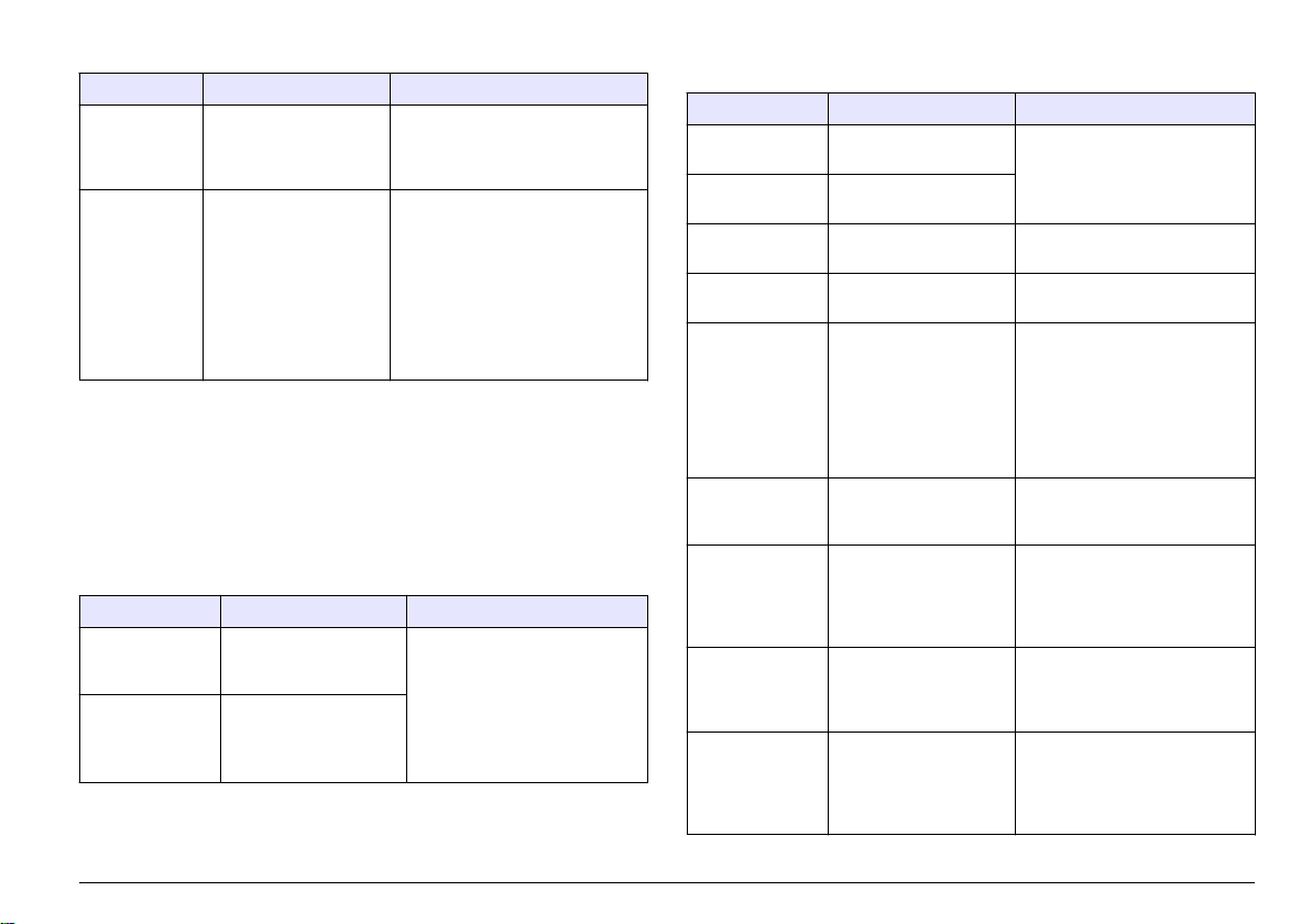
Tableau 6 Liste d'erreurs pour les capteurs de conductivité (suite)
Erreur Description Résolution
CAPTEUR
MANQUANT
CAPT HORS
ECH
Le capteur est manquant
ou débranché
Le signal du capteur est
en dehors des limites
acceptées pour la
constante de cellule
utilisée (0,01 et 0,05 :
100 µS/cm ; 0,5 :
1 000 µS/cm ; 1 :
2 000 µS/cm ; 5 :
10 000 µS/cm ; 10 :
200 000 µS/cm)
Contrôlez le câblage et les
connexions du capteur et du
module. S'assurer que le bornier
est inséré à fond dans le module.
Assurez-vous que le capteur est
configuré pour la constante de
cellule correcte.
Liste d’avertissements pour les capteurs
Un avertissement n'affecte pas le fonctionnement des menus, relais et
sorties. Une icône d'avertissement clignote et un message apparaît en
bas de l'écran de mesure. Pour afficher les avertissements de capteur,
appuyer sur la touche MENU puis sélectionner Diagn. capteur,
[Sélectionner le capteur], Liste avertis. Une liste d'avertissements
possibles apparaît dans le Tableau 7.
Tableau 7 Liste d'avertissements des capteurs de conductivité
Avertissement Description Résolution
ZERO TROP
HAUT
ZERO TROP BAS La valeur d'étalonnage
La valeur d'étalonnage
de zéro est >
300 000 points
de zéro est
< –300 000 points
S'assurer que le capteur est tenu
dans l'air pendant l'étalonnage
de zéro et qu'il ne se trouve pas
près d'une source
d'interférences de fréquences
radio ou électromagnétiques.
S'assurer que le câble est blindé
par une gaine métallique.
Tableau 7 Liste d'avertissements des capteurs de conductivité
(suite)
Avertissement Description Résolution
TEMP TROP
HAUTE
TEMP TROP
BASSE
RETARD ETAL Le délai de rappel
NON ETALONNE Le capteur n'a pas été
REMPL.
CAPTEUR
ETAL EN COURS Un étalonnage a été
SORTIES MEMO Pendant l'étalonnage,
TC LINEAIRE
ERRONE
TABLE TC ERR La table de
La température mesurée
est > 100 °C
La température mesurée
est < 0 °C
d'étalonnage est écoulé
étalonné.
Le capteur a fonctionné
> 365 jours
commencé mais n'a pas
été achevé
les sorties ont été
placées en maintien
pendant une durée
sélectionnée.
La compensation de
température linéaire
définie par l'utilisateur
est hors plage.
compensation de
température définie par
l'utilisateur est hors
plage.
S'assurer que le capteur est
configuré pour l'élément de
température correct.
Etalonner le capteur.
Etalonner le capteur.
Etalonner le capteur avec une
solution de référence et remettre
à zéro le nombre de jours du
capteur. Reportez-vous à la
Menu de diagnostic et test du
capteur à la page 33. En cas
d'échec de l'étalonnage, appeler
le support technique.
Revenir à l'étalonnage.
Les sorties redeviendront actives
après la durée sélectionnée.
La valeur doit être entre 0 et
4%/°C ; 0 à 200 °C.
La température est au-dessus
ou en-dessous de la plage de
température définie par la table.
Français 35
Page 36
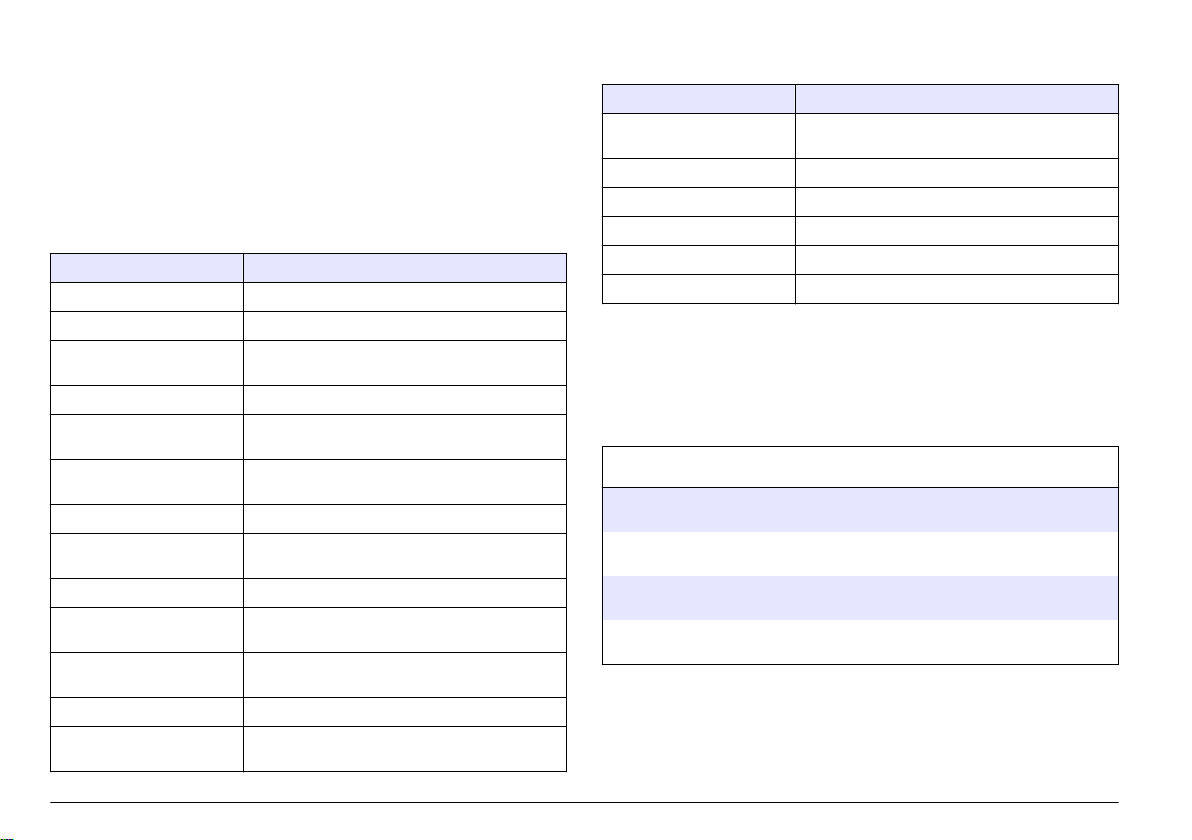
Liste d'événements pour les capteurs
La liste d'événements affiche les activités en cours telles que
modification de configuration, alarmes, avertissements, etc. Pour afficher
les événements, appuyer sur la touche MENU puis sélectionner Diagn.
capteur, [Sélectionner le capteur], Liste d'événements. Une liste des
événements possibles apparaît dans le Tableau 8. Les événements
précédents sont enregistrés dans le journal d'événements, qui peut être
téléchargé depuis le contrôleur. Reportez-vous à la documentation du
transmetteur pour les options d'extraction de données.
Tableau 8 Liste d'événements pour les capteurs de conductivité
Evénement Description
ETAL PRET Le capteur est prêt pour l'étalonnage.
ETA OK L'étalonnage en cours est correct
TEMPS ECOULE Le temps de stabilisation pendant l'étalonnage est
écoulé
ECHEC ETAL L'étalonnage a échoué
ETAL HAUT La valeur d'étalonnage est au-dessus de la limite
supérieure
K HORS PLAGE La constante de cellule K est hors de la plage
d'étalonnage en cours
INSTABLE La valeur lue pendant l'étalonnage était instable
MODIF CONFIG FLOTTANT La configuration a été modifiée — type en virgule
flottante
MODIF CONFIG TEXTE La configuration a été modifiée — type texte
MODIF CONFIG ENTIER La configuration a été modifiée — valeur de type
entier
VAL DEFAUT La configuration a été réinitialisée aux options par
défaut
INFO ALIMENTAT L'alimentation a été activée
DEFAUT ADC La conversion analogique-numérique a échoué
(panne matérielle)
Tableau 8 Liste d'événements pour les capteurs de conductivité
(suite)
Evénement Description
FLASH ERASE Un effacement de la mémoire flash externe série
TEMPERATURE La température est hors plage (-20 à 200 °C)
DEBUT ETAL ECHANT Début d'étalonnage en conductivité
FIN ETAL ECHANT Fin d'étalonnage en conductivité
DEBUT ETAL ZERO Début d'étalonnage de zéro
FIN ETAL ZERO Fin d'étalonnage de zéro
est survenu
Pièces et accessoires de rechange
Remarque : Les numéros de référence de produit et d'article peuvent dépendre
des régions de commercialisation. Prenez contact avec le distributeur approprié ou
consultez le site web de la société pour connaître les personnes à contacter.
Consommables
Descriptions Quantité Article No.
Solution de référence de conductivité,
100–1000 µS/cm
Solution de référence de conductivité,
1000–2000 µS/cm
Solution de référence de conductivité,
2000–150 000 µS/cm
Solution de référence de conductivité,
200 000–300 000 µS/cm
1 l 25M3A2000-119
1 l 25M3A2050-119
1 l 25M3A2100-119
1 l 25M3A2200-119
36 Français
Page 37
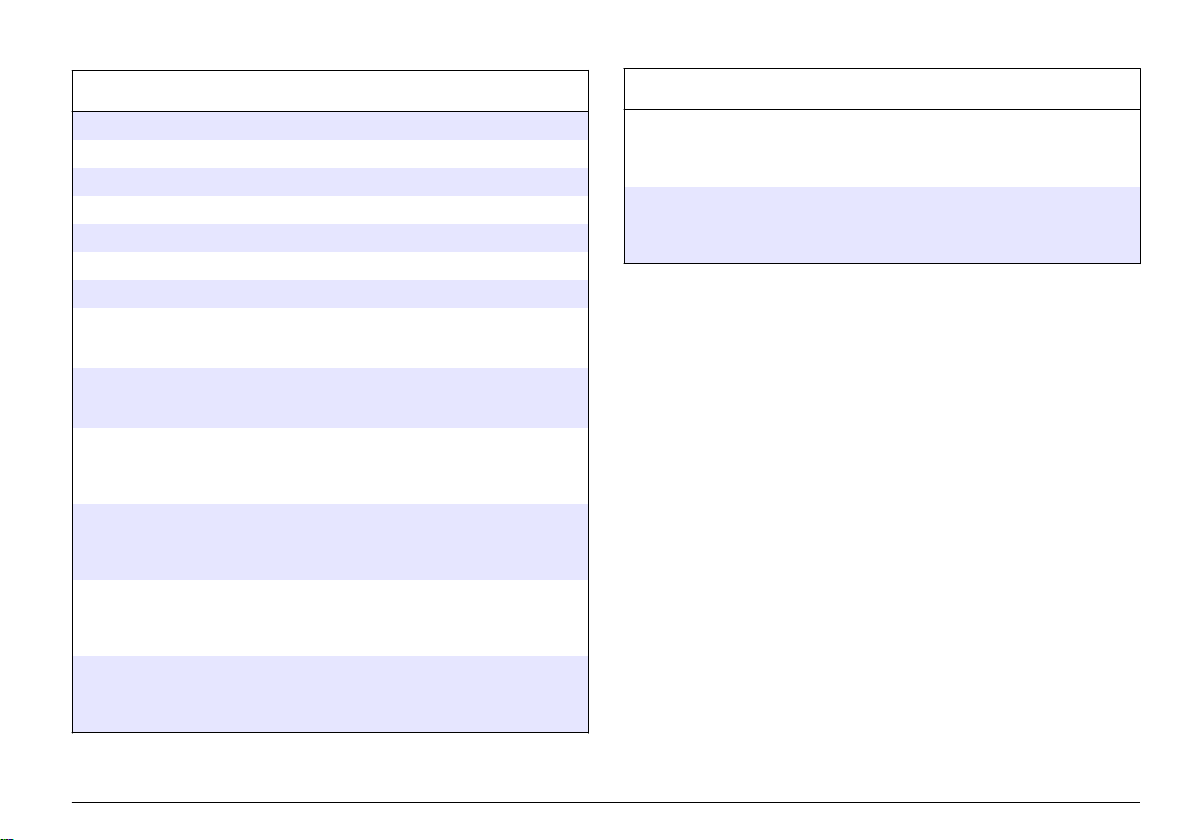
Pièces et accessoires
Pièces et accessoires (suite)
Descriptions Article No.
Câble, 5 m (16 ft) 08319=A=0005
Câble, 10 m (33 ft) 08319=A=0010
Câble, 20 m (66 ft) 08319=A=0020
Chambre de drainage, 6 mm (¼ po) filetage NPT 08318=A=0001
Chambre de circulation, 19 mm (¾ po) filetage NPT 08313=A=0001
Joint, EPDM, 38 mm (1,5 po) 429=500=380
Joint, EPDM, 51 mm (2 po) 429=500=510
Kit de montage avec joint EPDM, élément de fixation et
virole en acier inoxydable (h = 13 mm), diamètre intérieur
de 38 mm (1,5 po), diamètre extérieur de 64 mm (2,52 po)
Kit de montage avec joint EPDM, élément de fixation et
virole en acier inoxydable (h = 13 mm), diamètre intérieur
de 51 mm (2 po), diamètre extérieur de 64 mm (2,52 po)
Kit de montage avec joint EPDM, élément de fixation et
chambre de circulation en acier inoxydable, diamètre
intérieur de 38 mm (1,5 po), diamètre extérieur de 64 mm
(2,52 po)
Kit de montage avec joint EPDM, élément de fixation et
chambre de circulation en acier inoxydable, diamètre
intérieur de 51 mm (2 po), diamètre extérieur de 64 mm
(2,52 po)
Certificat, le certificat de test standard définit la valeur
réelle de la constante de cellule à ± 2 % conformément
aux normes ISO 7888 et ASTM D5391 ; diamètre extérieur
de 64 mm (2,52 po)
Certificat, certificat de conformité en option (matériaux
agréés par la FDA, acier inoxydable conforme à
l'EN 10204 3.1 B, coefficient de rugosité < 0,4 µm) ;
diamètre extérieur de 64 mm (2,52 po)
08394=A=0380
08394=A=0510
08394=A=8150
08394=A=8200
08394=A=1500
08394=A=1511
Descriptions Article No.
Certificat, le certificat de test standard définit la valeur
réelle de la constante de cellule à ± 2 % conformément
aux normes ISO 7888 et ASTM D5391 ; diamètre extérieur
de 64 mm (2,52 po)
Certificat, certificat de conformité en option (matériaux
agréés par la FDA, acier inoxydable conforme à
l'EN 10204 3.1 B, coefficient de rugosité < 0,4 µm) ;
diamètre extérieur de 64 mm (2,52 po)
08394=A=2000
08394=A=2011
Français 37
Page 38

Tabla de contenidos
Especificaciones en la página 38 Mantenimiento en la página 52
Información general en la página 39 Solución de problemas en la página 53
Instalación en la página 41 Piezas de repuesto y accesorios
en la página 56
Funcionamiento en la página 46
Especificaciones
Las especificaciones están sujetas a cambios sin previo aviso.
Tabla 1 Especificaciones del módulo
Especificación Detalles
Rango de medición Constante de la celda 0,01:
0,01-200 µS/cm
Constante de la celda 0,1:
0,1 µS–2 mS/cm
Constante de la celda 1: 1 µS–20 mS/cm
Tiempo de respuesta 0,5 segundos
Repetibilidad/precisión (0-20 µS/cm) ±0.1/0.1 µS/cm
Precisión (20-200,000 µS/cm) ±0,5% de la lectura
Largo máximo del cable 91 m (299 pies)
Tabla 2 Especificaciones del sensor
Especificación Detalles
Elemento de temperatura PT100
Cable del sensor 4 conductores (más 2 blindajes); 5 m (16 pies),
10 m (33 pies) o 20 m (66 pies); valorados a
150 °C (302 °F)
Tabla 2 Especificaciones del sensor (continúa)
Especificación Detalles
Materiales impregnados - serie
8310
Materiales impregnados - serie
8311
Materiales impregnados - serie
8312
Materiales impregnados - serie
8315
Materiales impregnados - serie
8316
Materiales impregnados - serie
8317
Materiales impregnados - serie
8394
Cuerpo de PSU color negro, electrodo interno
de acero inoxidable 316L, electrodo externo de
acero inoxidable 316L, aislador PSU y
conector IP65/de poliéster con fibra de vidrio
Cuerpo de PSU color negro, electrodo interno
de acero inoxidable 316L, electrodo externo de
acero inoxidable 316L, aislador PSU y
conector IP65/de poliéster con fibra de vidrio
Cuerpo de PSU color negro, electrodo interno
de granito, electrodo externo de granito,
aislador PSU y conector con fibra de
vidrio/IP65
Cuerpo de acero inoxidable 316L, electrodo
interno de acero inoxidable 316L, electrodo
externo de acero inoxidable 316L, aislador
PSU, junta tórica Viton® y conector de poliéster
con fibra de vidrio/IP65
Cuerpo de acero inoxidable 316L, electrodo
interno de acero inoxidable 316L, electrodo
externo de acero inoxidable 316L, aislador
PSU, junta tórica Viton y conector de poliéster
con fibra de vidrio/IP65
Cuerpo de acero inoxidable 316L, electrodo
interno de grafito, electrodo externo de grafito,
aislador PES, junta tórica Viton y conector de
poliéster con fibra de vidrio/IP65
Cuerpo de acero inoxidable, electrodo 316L,
PEEK®, junta EPDM y conector de poliéster
con fibra de vidrio/IP65
38 Español
Page 39

Tabla 2 Especificaciones del sensor (continúa)
Especificación Detalles
Límite de temperatura/presión
—serie 8315, 8316, 8317 o
1
8394
Límite de temperatura/presión
—serie 8310, 8311 o 8312
150 °C (302 °F) a 25 bar (362,5 psi)
125 °C (257 °F) a 10 bar (145 psi)
Información general
En ningún caso el fabricante será responsable de ningún daño directo,
indirecto, especial, accidental o resultante de un defecto u omisión en
este manual. El fabricante se reserva el derecho a modificar este
manual y los productos que describen en cualquier momento, sin aviso
ni obligación. Las ediciones revisadas se encuentran en la página web
del fabricante.
Uso de la información sobre riesgos
P E L I GR O
Indica una situación potencial o de riesgo inminente que, de no evitarse,
provocará la muerte o lesiones graves.
A D V E RT EN CI A
Indica una situación potencial o inminentemente peligrosa que, de no evitarse,
podría provocar la muerte o lesiones graves.
P R E C AU CI ÓN
Indica una situación potencialmente peligrosa que podría provocar una lesión
menor o moderada.
Indica una situación que, si no se evita, puede provocar daños en el instrumento.
Información que requiere especial énfasis.
A V I S O
Información de seguridad
A V I S O
El fabricante no es responsable de ningún daño debido a un mal uso de este
producto incluyendo, sin limitación, daños directos, fortuitos o circunstanciales y
reclamaciones sobre los daños que no estén recogidos en la legislación vigente.
El usuario es el responsable de la identificación de los riesgos críticos y de tener
los mecanismos adecuados de protección de los procesos en caso de un posible
mal funcionamiento del equipo.
Etiquetas de precaución
Lea todas las etiquetas y rótulos adheridos al instrumento. En caso
contrario, podrían producirse heridas personales o daños en el
Lea todo el manual antes de desembalar, instalar o trabajar con este
equipo. Ponga atención a todas las advertencias y avisos de peligro. El
no hacerlo puede provocar heridas graves al usuario o daños al equipo.
Asegúrese de que la protección proporcionada por el equipo no está
dañada. No utilice ni instale este equipo de manera distinta a lo
especificado en este manual.
1
Otras marcas de hardware de montaje y abrazaderas sanitarias pueden reducir la valoración indicada.
Español 39
Page 40
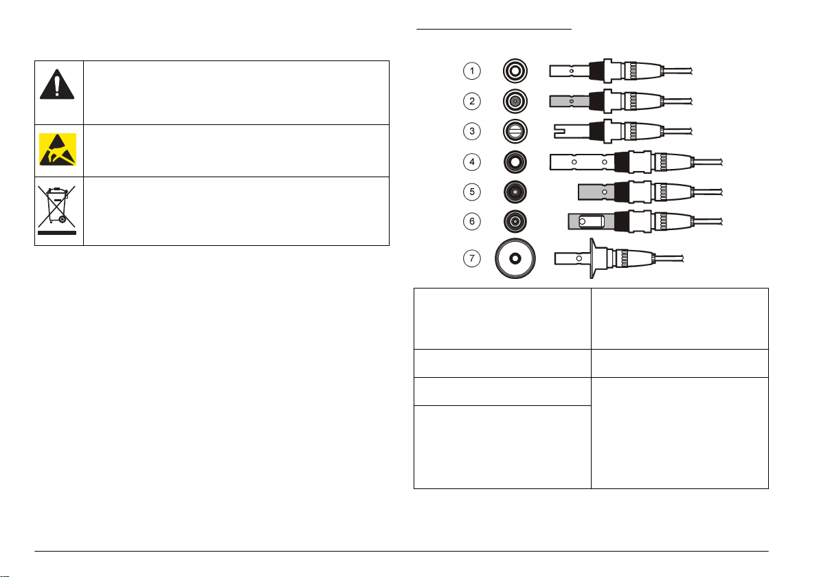
instrumento. El símbolo que aparezca en el instrumento se comentará
en el manual con una declaración de precaución.
Este es un símbolo de alerta de seguridad. Obedezca todos los
mensajes de seguridad que se muestran junto con este símbolo para
evitar posibles lesiones. Si se encuentran sobre el instrumento,
consulte el manual de instrucciones para obtener información de
funcionamiento o seguridad.
Este símbolo indica la presencia de dispositivos susceptibles a
descargas electrostáticas. Asimismo, indica que se debe tener
cuidado para evitar que el equipo sufra daño.
En Europa, el equipo eléctrico marcado con este símbolo no se debe
desechar mediante el servicio de recogida de basura doméstica o
pública. Devuelva los equipos viejos o que hayan alcanzado el
término de su vida útil al fabricante para su eliminación sin cargo
para el usuario.
Descripción general del producto
Este sensor está diseñado para trabajar con un controlador para la
recolección de datos y operación. Con este sensor se pueden utilizar
varios controladores.
El sensor se encuentra disponible en estilos diferentes. Consulte el
apartado Figura 1.
Figura 1 Estilos de sensores
1 8310, k = 0,01; las aplicaciones
incluyen agua potable, tratamiento
de aguas residuales, procesos
químicos, agua desmineralizada y
blanda
2 8311, k = 0,1; las mismas
aplicaciones que 8310
3 8312, k = 1; las mismas
aplicaciones que 8310
4 8315, k = 0,01; las aplicaciones
incluyen control de producción de
agua pura (destiladores e
intercambiadores iónicos) y control
de procesamiento de aguas
(condensación, ciclos de limpieza e
intercambiador de calor)
5 8316, k = 0,1; las mismas
aplicaciones que 8315
6 8317, k = 1; las mismas
aplicaciones que 8315
7 8394, k = 0,01; estilo sanitario;
1,5 o 2" de diámetro; las
aplicaciones incluyen control de
agua ultrapura en el sector
farmacéutico y alimentario,
idoneidad para procesos CIP-SIP
40 Español
Page 41

Instalación
Montaje
Figura 2 Ejemplos de montaje sanitario
A D V E RT EN CI A
Peligro de lesión personal. Extraer un sensor de un recipiente presurizado puede
ser peligroso. La instalación y retirada de estos sensores debe realizarla
personal cualificado, capaz de llevar a cabo una instalación apropiada a
temperatura y presión alta. Utilice siempre procedimientos de seguridad y
hardware aprobado por el sector cuando trabaje con sistemas de transporte de
líquidos a temperatura o presión alta.
Para ejemplos de sensores en diferentes aplicaciones, consulte la
Figura 2 o la Figura 3.Es necesario calibrar el sensor antes de utilizarlo.
Consulte la Calibrar el sensor en la página 47.
1 Abrazadera sanitaria 3 Casquillo (soldado al tubo)
2 Junta 4 Cámara de flujo
Español 41
Page 42

Figura 3 Ejemplos de montaje
1 3/4--pulg. NPT 2 1/4--pulg. NPT
42 Español
Page 43

Conecte el sensor al módulo
A D V E RT EN CI A
Posible peligro de electrocución. Desconecte siempre el instrumento
del suministro eléctrico antes de realizar conexiones eléctricas.
A D V E RT EN CI A
Peligro de electrocución. El cableado de alto voltaje para el controlador se realiza
detrás de la barrera de alto voltaje en la carcasa del controlador. La barrera debe
permanecer en su lugar excepto durante la instalación de módulos o cuando un
técnico de instalación cualificado esté realizando el cableado de alimentación, de
los relés o de las tarjetas analógicas y de red.
Daño potencial al instrumento. Los delicados componentes
electrónicos internos pueden sufrir daños debido a la electricidad
estática, lo que acarrea una disminución del rendimiento del
instrumento o posibles fallos.
Para instalar el módulo y conectar el sensor, consulte los pasos
ilustrados de las páginas siguientes y la Tabla 3. Asegúrese de conectar
el cable blanco con el extremo rojo desde el sensor al chasis del
controlador.
Nota: Si el cable del sensor no es lo suficientemente largo como para llegar al
controlador, se necesita un cable de interconexión y una caja de conexión para
ampliar la distancia. .
A V I S O
Tabla 3 Cableado de los sensores de conductividad de Polymetron
Nro. de pin conector Señal Cable del sensor
1 Salida Blanco
2 — —
3 Conexión a tierra Negro
4 — —
5 — —
6 — —
7 Temp – Negro
8 — —
9 — —
10 Temp + Azul
11 Entrada Rojo
12 — —
Español 43
Page 44

1 2
3 4
44 Español
Page 45

5 6
7 8
Español 45
Page 46

Funcionamiento
Desplazamiento del usuario
Consulte la documentación del controlador para ver la descripción del
teclado e información sobre cómo desplazarse.
Configuración del sensor
Utilice el menú Configurar para introducir la información de identificación
del sensor y para cambiar las opciones para el manejo y
almacenamiento de datos.
1. Pulse la tecla MENU y seleccione Configuración del sensor,
[seleccione el sensor], Configurar.
2. Utilice las teclas de desplazamiento del cursor para seleccionar una
opción y pulse ENTER. Para introducir números, caracteres o signos
de puntuación, pulse y mantenga presionada la tecla con la flecha
hacia ARRIBA o hacia ABAJO. Pulse la tecla DERECHA para
avanzar al siguiente espacio.
Opción Descripción
EDITAR NOMBRE Cambia el nombre que corresponde al sensor en la
Nº SECUENCIAL
DEL SENSOR
SELECCIONAR
MEDIDA
parte superior de la pantalla de medición. El nombre
puede contener hasta 10 caracteres en cualquier
combinación de letras, números, espacios o signos
de puntuación.
Permite al usuario ingresar el número de serie del
sensor, limitado a 16 caracteres en cualquier
combinación de letras, números, espacios o signos
de puntuación.
Cambia el parámetro medido a conductividad
(configuración predeterminada), TSD (total de sólidos
disueltos), salinidad o resistividad. Al cambiar el
parámetro, todas las demás configuraciones se
restablecen a los valores predeterminados.
Opción Descripción
FORMATO DE
PANTALLA
UNIDADES DE
MEDIC
UNIDADES DE
TEMP
COMPENSACIÓN
TEMP
CONSTANTE
CUBETA
LONGITUD DEL
CABLE
Cambia la cantidad de posiciones decimales que se
pueden ver en la pantalla de medición a la modalidad
automática (configuración predeterminada), X,XXX,
XX,XX, XXX,X o XXXX. Al configurarla en modalidad
automática, la cantidad de posiciones decimales
cambia automáticamente con los cambios del valor
medido.
Cambia las unidades de la medición seleccionada,
conductividad: µS/cm (por defecto), mS/cm, µS/m,
mS/m o S/m.
Configura las unidades de temperatura en ºC
(configuración predeterminada) o ºF..
Añade una corrección dependiente de la temperatura
al valor medido: lineal (por defecto: 2,0%/°C, 25 °C),
amoniaco, tabla de temperatura (introduzca los
puntos x,y en orden ascendente), ninguna, agua
natural o agua pura. Para las aplicaciones
especiales, se puede ingresar una compensación
lineal definida por el usuario (0-4%/°C, 0-200 °C). La
opción de compensación con agua natural no está
disponible para el TSD.
Establece el rango de la constante de la celda a 0,05,
0,5, 1,0 (por defecto), 5,0, 10,0, 0,01 (polymetron),
0,1 (polymetron) o 1,0 (polymetron). Después de
seleccionar el rango, el usuario puede ingresar el
valor K certificado de la etiqueta en el cable del
sensor. Al ingresar el valor K certificado, se define la
curva de calibración.
Establece la longitud real del cable del sensor para
mejorar la exactitud de la medición (por defecto:
20 pies, valor por defecto para sensores de
polymetron: 5 pies)).
46 Español
Page 47

Opción Descripción
ELEMENTO TEMP Configura el elemento de temperatura para la
FILTRO Configura una constante de tiempo para incrementar
CONFIG REGISTRO Configura el intervalo de tiempo para el
REST CONFIG
PREDET
compensación automática de la temperatura en
PT100 o PT1000 (configuración predeterminada).
Luego de hacer la selección, el usuario debe ingresar
el factor T certificado de la etiqueta en el cable del
sensor para lograr la mejor precisión posible. En caso
de no utilizar ningún elemento, el tipo se puede
configurar en manual y se puede ingresar un valor
para la compensación de la temperatura
(configuración predeterminada manual: 25 °C).
Nota: Si un sensor con un elemento PT100 o
PT1000 se establece en manual y se sustituye el
sensor o se restablecen los días del sensor, el
ELEMENTO TEMP cambia automáticamente al
ajuste por defecto.
la estabilidad de la señal. La constante de tiempo
calcula el valor promedio durante un tiempo
determinado: desde 0 (sin efecto, configuración
predeterminada) hasta 60 segundos (promedio de
valor de la señal para 60 segundos). El filtro
incrementa el tiempo de la señal del sensor para
responder a los cambios reales del proceso.
almacenamiento de datos en el registro de datos: 5,
30 segundos, 1, 2, 5, 10, 15 (configuración
predeterminada), 30, 60 minutos.
Configura el menú de configuración a los valores
predeterminados. Se perderán todos los valores
definidos por el usuario.
Regule el factor T para los largos de cable que no son los estándar
Al alargar o acortar el cable del sensor de los 6 mts. estándar (20 pies),
la resistencia del cable cambia. Este cambio disminuye la precisión de
las mediciones de temperatura. Para corregir esta diferencia, calcule un
nuevo factor T.
Nota: Este procedimiento tiene aplicación únicamente en los sensores con un
elemento de temperatura PT1000. Los sensores con un elemento de temperatura
PT100 son menos precisos.
1. Mida la temperatura de una solución con el sensor y con un
instrumento confiable independiente como, por ejemplo, un
termómetro.
2. Registre la diferencia entre la temperatura medida con el sensor y la
medida con la fuente independiente (real).
Por ejemplo, si la temperatura real es 50 °C y la lectura del sensor
es 53 °C, la diferencia es de 3 °C.
3. Multiplique esta diferencia por 3,85 y obtenga un valor de ajuste.
Ejemplo: 3 x 3,85 = 11,55.
4. Calcule un factor T nuevo.
• Temperatura del sensor > real: agregue el valor de ajuste al factor
T en el cable del sensor
• Temperatura del sensor < real: reste el valor de ajuste al factor T
en el cable del sensor
5. Ingrese el nuevo factor T en el menú Configurar > Elemento de
temperatura.
Calibrar el sensor
Acerca de la calibración del sensor
Durante la calibración, los datos no se envían al registro de datos. De
este modo, el registro de datos puede tener áreas en las que los datos
sean intermitentes.
Procedimiento de calibración a cero
Utilice el procedimiento de calibración a cero para definir el punto cero
exclusivo del sensor de conductividad. El punto cero se debe definir
antes de calibrar el sensor por primera vez con una solución de
referencia o con una muestra del proceso.
Español
47
Page 48

1. Retire el sensor del proceso. Pase un paño limpio por el sensor o
utilice aire comprimido para asegurarse de que el sensor está limpio
y seco.
2. Pulse la tecla MENU (Menú) y seleccione Sensor Setup
(Configuración del sensor), [seleccione el sensor], Calibrate
(Calibrar).
3. Pulse la tecla ENTER para seleccionar CAL CERO.
4. En caso de que la contraseña esté habilitada en el menú de
seguridad del controlador, introdúzcala.
5. Seleccione la opción de la señal de salida durante la calibración:
Opción Descripción
Active (Activo) Durante el proceso de calibración el instrumento
Hold (Retenido) Durante el proceso de calibración el valor de salida
Transfer
(Transferencia)
envía el valor de medición actual de salida.
del sensor se mantiene en el valor de medición
actual.
Durante la calibración se envía un valor de salida
predeterminado. Consulte el manual del usuario del
controlador para cambiar el valor predeterminado.
6. Sostenga el sensor seco en el aire y presione ENTER.
7. Revise el resultado de la calibración:
• Aprobado: se configuró el punto cero.
• No aprobado: el valor se encuentra fuera de los límites aceptados.
Asegúrese de que el sensor esté seco y repita el procedimiento
de calibración a cero. Asegúrese de que el motivo no está en el
cable de extensión o en un lote de ruido electrónico.
8. Si la calibración fue aprobada, pulse ENTER para continuar.
9. Para el controlador sc100, vaya al paso 12.
10. En caso que la opción para la identificación del operador esté
configurada en Sí en el menú Opciones de calibración, ingrese un
identificador. Consulte Cambio de las opciones de calibración
en la página 51.
11. En la pantalla Sensor nuevo, seleccione si el sensor es nuevo o no:
Opción Descripción
Sí El sensor no fue calibrado anteriormente con este controlador. Los
días de funcionamiento y las curvas de calibraciones anteriores del
sensor están restablecidas.
No El sensor fue calibrado anteriormente con este controlador.
12. Proceda con la calibración con una solución de referencia o con una
muestra del proceso.
Calibración mediante una solución de referencia
La calibración ajusta la lectura del sensor para que coincida con el valor
de una solución de referencia. Utilice una solución de referencia que
tenga el mismo valor o un valor mayor a las lecturas de medición
deseadas.
Nota: En caso de que sea la primera calibración del sensor, asegúrese de realizar
la calibración a cero en primer lugar.
1. Enjuague bien el sensor limpio en agua desionizada.
2. Coloque el sensor en la solución de referencia. Sosténgalo de modo
que no toque el recipiente. Asegúrese de que el área sensora quede
completamente sumergida en la solución (Figura 4). Agite el sensor
para eliminar las burbujas.
48 Español
Page 49
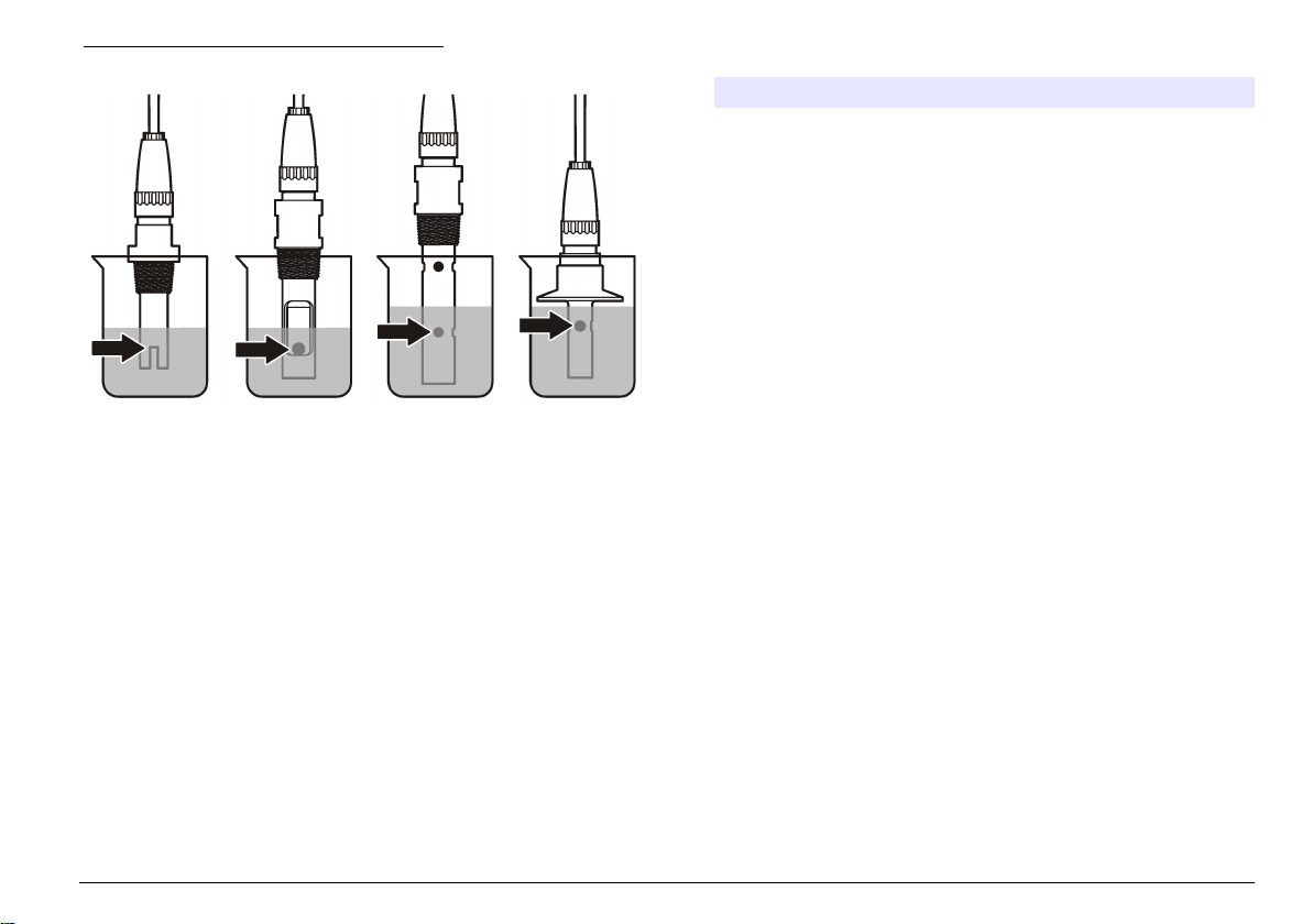
Figura 4 Sensor en solución de referencia
3. Espere a que la temperatura del sensor y de la solución sean
uniformes. Esto puede demorar 30 minutos o más si la diferencia de
temperatura entre la solución del proceso y la solución de referencia
es significativa.
4. Pulse la tecla MENU (Menú) y seleccione Sensor Setup
(Configuración del sensor), [seleccione el sensor], Calibrate
(Calibrar).
5. Seleccione la calibración para el parámetro especificado y pulse
ENTER:
• Conductividad: Cal cond
• TSD: CAL TSD
• Salinidad: Cal cond
• Concentración: Cal conc o Cal cond
6. En caso de que la contraseña esté habilitada en el menú de
seguridad del controlador, introdúzcala.
7. Seleccione la opción de la señal de salida durante la calibración:
Opción Descripción
Active (Activo) Durante el proceso de calibración el instrumento
Hold (Retenido) Durante el proceso de calibración el valor de salida
Transfer
(Transferencia)
envía el valor de medición actual de salida.
del sensor se mantiene en el valor de medición
actual.
Durante la calibración se envía un valor de salida
predeterminado. Consulte el manual del usuario del
controlador para cambiar el valor predeterminado.
8. Con el sensor en la solución de referencia, pulse ENTER.
9. Ingrese la temperatura de referencia de la solución de referencia y
pulse ENTER.
10. Ingrese la pendiente de la solución de referencia y pulse ENTER.
11. Espere hasta que el valor se estabilice y pulse ENTER (Intro).
Nota: Posiblemente la pantalla avance automáticamente al siguiente paso.
12. Utilice las teclas de desplazamiento del cursor para ingresar el valor
de la solución de referencia y pulseENTER
13. Revise el resultado de la calibración:
• Aprobado: el sensor está calibrado y listo para medir muestras.
Aparecen los resultados de la pendiente y/o el offset.
• No aprobado: la pendiente o el offset se encuentran fuera de los
límites aceptados. Vuelva a realizar la calibración con soluciones
de referencia nuevas. Consulte Mantenimiento en la página 52 y
Solución de problemas en la página 53 para obtener más
información.
14. Si la calibración fue aprobada, pulse ENTER para continuar.
15. En caso que la opción para la identificación del operador esté
configurada en Sí en el menú Opciones de calibración, ingrese un
identificador. Consulte Cambio de las opciones de calibración
en la página 51.
Español
49
Page 50

16. En la pantalla Sensor nuevo, seleccione si el sensor es nuevo o no:
Opción Descripción
Sí El sensor no fue calibrado anteriormente con este controlador. Los
días de funcionamiento y las curvas de calibraciones anteriores del
sensor están restablecidas.
No El sensor fue calibrado anteriormente con este controlador.
17. Vuelva el sensor al proceso y pulse ENTER.
Se vuelve a activar la señal de salida y en la pantalla de medición
aparece el valor de medición de la muestra.
Nota: En caso que la modalidad de salida esté configurada en Retenido o
Transferencia, seleccione el tiempo de demora cuando las salidas se vuelven
a activar.
Calibración con la muestra del proceso
El sensor puede permanecer en la muestra del proceso o se puede
extraer una parte de la muestra del proceso para la calibración.
1. Pulse la tecla MENU (Menú) y seleccione Sensor Setup
(Configuración del sensor), [seleccione el sensor], Calibrate
(Calibrar).
2. Seleccione la calibración para el parámetro especificado y pulse
ENTER:
• Conductividad: Cal cond
• TSD: CAL TSD
• Salinidad: Cal cond
• Concentración: Cal conc o Cal cond
3. En caso de que la contraseña esté habilitada en el menú de
seguridad del controlador, introdúzcala.
4. Seleccione la opción de la señal de salida durante la calibración:
Opción Descripción
Active (Activo) Durante el proceso de calibración el instrumento
envía el valor de medición actual de salida.
Opción Descripción
Hold (Retenido) Durante el proceso de calibración el valor de salida
Transfer
(Transferencia)
del sensor se mantiene en el valor de medición
actual.
Durante la calibración se envía un valor de salida
predeterminado. Consulte el manual del usuario del
controlador para cambiar el valor predeterminado.
5. Con el sensor en la muestra del proceso, pulse ENTER.
Aparecerá el valor de la medición.
6. Espere que el valor se estabilice y pulse ENTER.
7. Utilice las teclas de desplazamiento del cursos para ingresar el valor
de la muestra del proceso y pulse ENTER
8. Revise el resultado de la calibración:
• Aprobado: el sensor está calibrado y listo para medir muestras.
Aparecen los resultados de la pendiente y/o el offset.
• No aprobado: la pendiente o el offset se encuentran fuera de los
límites aceptados. Vuelva a realizar la calibración con soluciones
de referencia nuevas. Consulte Mantenimiento en la página 52 y
Solución de problemas en la página 53 para obtener más
información.
9. Si la calibración fue aprobada, pulse ENTER para continuar.
10. En caso que la opción para la identificación del operador esté
configurada en Sí en el menú Opciones de calibración, ingrese un
identificador. Consulte Cambio de las opciones de calibración
en la página 51.
11. En la pantalla Sensor nuevo, seleccione si el sensor es nuevo o no:
Opción Descripción
Sí El sensor no fue calibrado anteriormente con este controlador. Los
No El sensor fue calibrado anteriormente con este controlador.
días de funcionamiento y las curvas de calibraciones anteriores del
sensor están restablecidas.
12. Vuelva el sensor al proceso y pulse ENTER.
50
Español
Page 51

Se vuelve a activar la señal de salida y en la pantalla de medición
aparece el valor de medición de la muestra.
Nota: En caso que la modalidad de salida esté configurada en Retenido o
Transferencia, seleccione el tiempo de demora cuando las salidas se vuelven
a activar.
Calibración de la temperatura
El instrumento viene calibrado de fábrica para medir la temperatura de
forma precisa. Se puede calibrar la temperatura para aumentar la
precisión.
1. Coloque el sensor en un contenedor de agua.
2. Mida la temperatura del agua con un termómetro de precisión o un
instrumento independiente.
3. Pulse la tecla MENU (Menú) y seleccione Sensor Setup
(Configuración del sensor), [seleccione el sensor], Calibrate
(Calibrar).
4. Seleccione 1 PT Temp Cal (Calibración de temperatura de 1 PT) y
pulse ENTER.
5. Espere hasta que el valor se estabilice y pulse ENTER (Intro).
6. Introduzca el valor exacto y pulse ENTER.
7. Vuelva el sensor al proceso y pulse ENTER.
Salida del procedimiento de calibración
El usuario puede salir de la calibración pulsando la tecla ATRÁS.
1. Pulse la tecla ATRÁS durante una calibración. Aparecerán tres
opciones:
Opción Descripción
SUSPENDER CAL Detiene el proceso de calibración. Se deberá
comenzar con una nueva calibración desde el
principio.
Opción Descripción
VOLVER A CAL Vuelve al proceso de calibración.
ABANDONAR CAL Sale del proceso de calibración provisoriamente. Se
permite el acceso a otros menús. Se puede iniciar la
calibración de un segundo sensor (en caso que lo
hubiera). Para volver al proceso de calibración, pulse
la tecla MENUy seleccione Configuración del sensor,
[seleccione el sensor].
2. Utilice las teclas de desplazamiento del cursor para seleccionar una
de las opciones y pulse ENTER.
Cambio de las opciones de calibración
El usuario puede configurar un recordatorio o incluir un identificador de
operador con los datos de la calibración en el menú OPCIONES DE
CAL.
1. Pulse la tecla MENU y seleccione Configuración del sensor,
[seleccione el sensor], Calibrar, Opciones de cal.
2. Utilice las teclas de desplazamiento del cursor para seleccionar una
opción y pulse ENTER.
Opción Descripción
RECORDAT CAL Establece un recordatorio para la próxima calibración en
ID DE OP de CAL Incluye una identificación del operador con los datos de
días, meses o años: apagado (configuración
predeterminada), 1 día, 7, 30, 60 o 90 días, 6 o
9 meses, 1 o 2 años
calibración: Sí o No (configuración predeterminada). La
identificación se ingresa durante la calibración.
Español 51
Page 52
Restablecimiento de las opciones de calibración
Las opciones de calibración se pueden restablecer a las opciones
predeterminadas de fábrica.
1. Pulse la tecla MENU y seleccione Configuración del sensor,
[seleccione el sensor], Calibrar, Restablecer calibración
predeterminada.
2. En caso de que la contraseña esté habilitada en el menú de
seguridad del controlador, introdúzcala.
3. Pulse ENTER. Aparece la pantalla Restablecer cal?
4. Pulse ENTER. Todas las opciones de calibración se configuran a los
valores predeterminados.
5. En caso que la opción para la identificación del operador esté
configurada en Sí en el menú Opciones de calibración, ingrese un
identificador. Consulte Cambio de las opciones de calibración
en la página 51.
6. En la pantalla Sensor nuevo, seleccione si el sensor es nuevo o no:
Opción Descripción
Sí El sensor no fue calibrado anteriormente con este controlador. Los
No El sensor fue calibrado anteriormente con este controlador.
días de funcionamiento y las curvas de calibraciones anteriores del
sensor están restablecidas.
7. Pulse la tecla ATRÁS para volver a la pantalla de medición.
Registros de Modbus
Está disponible una lista de registros Modbus para comunicación en red.
Consulte el sitio web del fabricante para obtener más información.
Mantenimiento
P E L I GR O
Peligros diversos. Sólo el personal cualificado debe realizar las tareas
descritas en esta sección del documento.
Limpieza del sensor
A D V E RT EN CI A
Peligro por exposición a productos químicos. Respete los
procedimientos de seguridad del laboratorio y utilice el equipo de
protección personal adecuado para las sustancias químicas que vaya
a manipular. Consulte los protocolos de seguridad en las hojas de
datos de seguridad actuales (MSDS/SDS).
A D V E RT EN CI A
Peligro de lesión personal. Extraer un sensor de un recipiente presurizado puede
ser peligroso. La instalación y retirada de estos sensores debe realizarla
personal cualificado, capaz de llevar a cabo una instalación apropiada a
temperatura y presión alta. Utilice siempre procedimientos de seguridad y
hardware aprobado por el sector cuando trabaje con sistemas de transporte de
líquidos a temperatura o presión alta.
Requisito previo: Prepare una solución de jabón suave con agua tibia y
detergente para lavar la vajilla, jabón de manos Borax o similar.
Revise periódicamente el sensor en busca de residuos y sedimentos.
Limpie el sensor cuando haya sedimentos acumulados o cuando el
rendimiento haya disminuido.
1. Saque los residuos sueltos del extremo del sensor con un paño
limpio de tela suave. Enjuague el sensor con agua limpia y tibia.
2. Ponga en remojo el sensor durante 2 ó 3 minutos en la solución
jabonosa.
3. Cepille todo el extremo medidor del sensor con un cepillo de cerdas
suaves.
4. Si los residuos no salen, sumerja el extremo medidor del sensor en
una solución ácida diluida como, por ejemplo, < 5% HCl durante
5 minutos como máximo.
5. Enjuague el sensor con agua y luego vuélvalo a colocar en la
solución jabonosa durante 2 a 3 minutos.
6. Enjuague el sensor con agua limpia.
52
Español
Page 53

Calibre siempre el sensor después de realizar los procedimientos de
mantenimiento.
Solución de problemas
Datos intermitentes
Durante la calibración, los datos no se envían al registro de datos. De
este modo, el registro de datos puede tener áreas en las que los datos
sean intermitentes.
Prueba del sensor de conductividad
En caso que una calibración no salga bien, primero realice los
procedimientos de mantenimiento de la sección Mantenimiento
en la página 52.
1. Desconecte los cables del sensor.
2. Utilice un ohmímetro para probar la resistencia entre los cables del
sensor como se muestra en la Tabla 4.
Nota: Asegúrese de que el ohmímetro esté configurado con el rango más alto
para todas las lecturas de resistencia infinita (circuito abierto).
Tabla 4 Mediciones de la resistencia de conductividad
Puntos de medición Resistencia
Entre el cable azul y el blanco 1089-1106 ohmios a 23-27 °C
Entre el cable rojo y el cuerpo del sensor Menos de 5 ohmios
Entre el cable negro y el electrodo interno Menos de 5 ohmios
Entre el cable negro y el rojo Infinita (circuito abierto)
Entre el cable negro y el blanco Infinita (circuito abierto)
Entre el cable rojo y el blanco Infinita (circuito abierto)
Entre el cable rojo y el cable conductor interno
protegido
Entre el cable negro y el cable conductor interno
protegido
Infinita (circuito abierto)
Infinita (circuito abierto)
Tabla 4 Mediciones de la resistencia de conductividad (continúa)
Puntos de medición Resistencia
Entre el cable blanco y el cable conductor
interno protegido
Entre el cable externo y el cable conductor
interno protegido
Infinita (circuito abierto)
Infinita (circuito abierto)
En caso que una o más de las mediciones sea incorrecta, póngase en
contacto con la asistencia técnica. Deberá proporcionar al servicio de
asistencia técnica el número de serie del sensor y los valores de
resistencia que ha medido.
Menú de prueba y diagnóstico del sensor
El menú de prueba y diagnóstico del sensor muestra la información
actual e histórica del instrumento. Consulte la Tabla 5. Para acceder a
este menú, pulse la tecla MENU y seleccione Configuración del sensor,
[seleccione el sensor], DIAG/PRUEBA.
Tabla 5 Menú DIAG/PRUEBA del sensor
Opción Descripción
INF SENSOR Muestra el nombre y el número de serie
INFO TARJETA Muestra la versión y el número de serie del módulo
CAL DAYS (Días de
calibración)
CAL HISTORY (Historial
de calibración)
REST HISTORIAL DE
CAL
SEÑALES DEL SENSOR Muestra la señal actual del sensor y el rango en
introducidos por el usuario.
del sensor.
Muestra el número de días desde la última
calibración.
Muestra una lista de calibraciones y detalles de
cada una de ellas.
Solo para uso de servicio. Restablece el historial de
calibración del sensor. Se perderán todos los datos
de las calibraciones anteriores.
µS/cm.
Español 53
Page 54
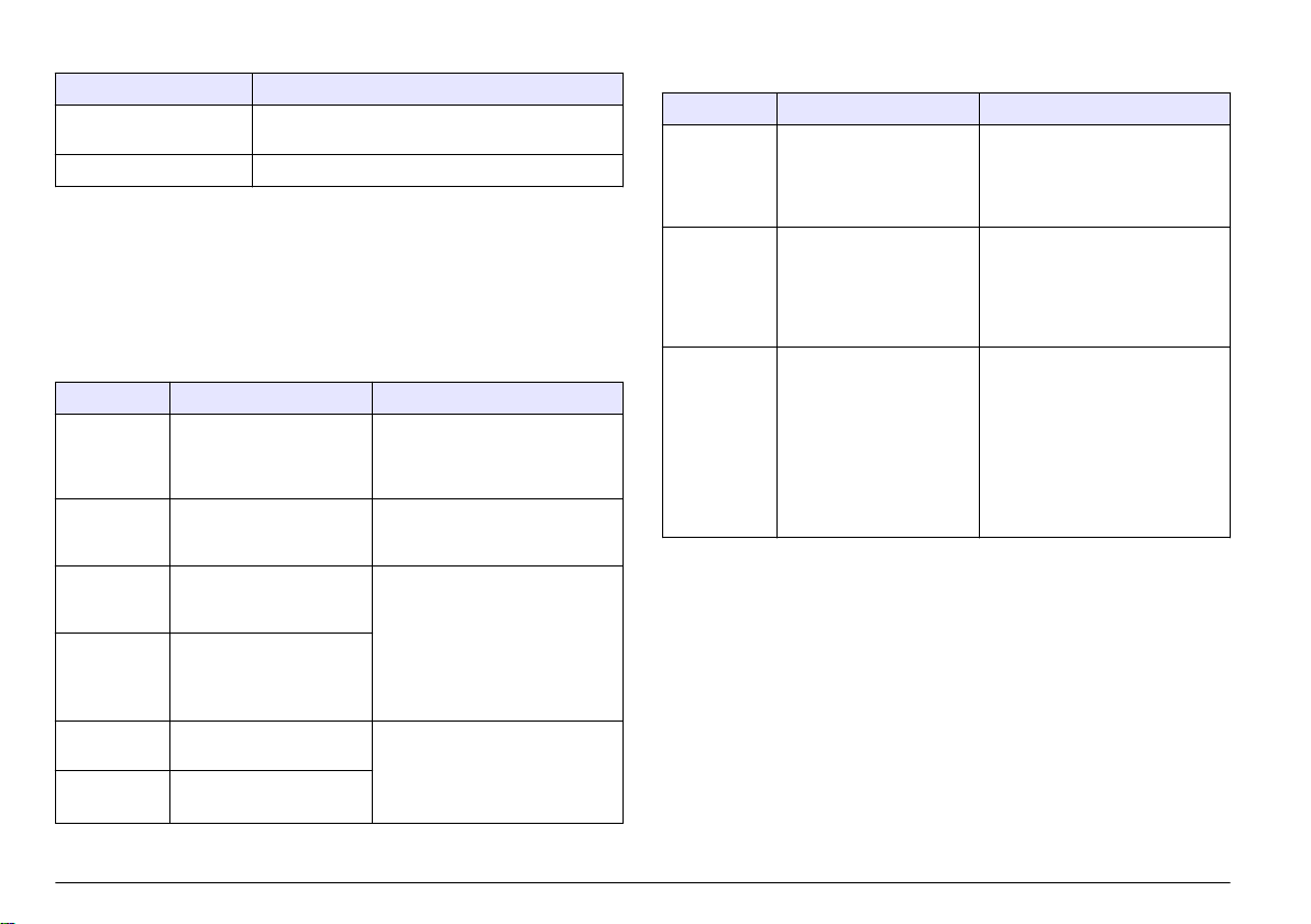
Tabla 5 Menú DIAG/PRUEBA del sensor (continúa)
Opción Descripción
SENSOR DAYS (Días del
sensor)
REST DÍAS SENSOR Restablece el contador del días del sensor.
Muestra el número de días en funcionamiento del
sensor.
Lista de errores
Cuando sucede un error, la lectura en la pantalla de medición parpadea
y se retienen todas las salidas cuando se especifica en el menú del
controlador. Para ver los errores del sensor, pulse la tecla MENU y
seleccione Diag del sensor, [seleccione el sensor], Lista de errores. En
la Tabla 6 aparece una lista de posibles errores.
Tabla 6 Lista de errores de los sensores de conductividad
Error Descripción Solución
MED MUY
ALTA
MED MUY
BAJA
CERO MUY
ALTO
CERO MUY
BAJO
TEMP MUY
ALTA
TEMP MUY
BAJA
El valor de la medición es
> 2.000.000 µS/cm,
1.000.000 ppm o
20.000 ppt
El valor de la medición es
< 0 µS/cm, 0 ppm o 0 ppt
El valor de la calibración
de cero es >
500.000 unidades
El valor de la calibración
de cero es <
-500.000 unidades
La medición de la
temperatura es > 130 °C
La medición de la
temperatura es < -10 °C
Asegúrese de que el sensor esté
configurado con la constante de
celda correcta.
Asegúrese de que el sensor esté
configurado con la constante de
celda correcta.
Asegúrese de que el sensor esté
en el aire durante la calibración de
cero y no se encuentre cerca de
una radiofrecuencia ni de una
interferencia electromagnética.
Asegúrese de que el cable esté
protegido con un conducto de
metal.
Asegúrese de que el sensor esté
configurado para el elemento de
temperatura apropiado. Consulte
la Prueba del sensor de
conductividad en la página 53.
Tabla 6 Lista de errores de los sensores de conductividad
(continúa)
Error Descripción Solución
FALLO DE
ADC
SENSOR
MISSING
(SENSOR
PERDIDO)
SENS FUERA
DE RANGO
Fallo del convertidor
analógico-digital
El sensor no está instalado
o está desconectado
La señal del sensor está
fuera de los límites
aceptados para la
constante de celda
utilizada (0,01 y 0,05:
100 µS/cm; 0,5:
1000 µS/cm; 1:
2000 µS/cm; 5:
10.000 µS/cm; 10:
200.000 µS/cm)
Asegúrese de que el módulo del
sensor esté completamente
introducido en el conector del
controlador. Cambie el módulo del
sensor.
Revise el cableado y las
conexiones del sensor y del
módulo. Asegúrese de que el
bloque de terminales esté
completamente introducido en el
módulo.
Asegúrese de que el sensor esté
configurado con la constante de
celda correcta.
Lista de advertencias para sensores
Una advertencia no afecta el funcionamiento de los menús, relés y
salidas. En la parte inferior de la pantalla de medición empieza a
parpadear un icono de advertencia y aparece un mensaje. Para ver las
advertencias del sensor, pulse la tecla MENU y seleccione Diag del
54
Español
Page 55

sensor, [seleccione el sensor], Lista de advertencias. En la Tabla 7
aparece una lista de advertencias posibles.
Tabla 7 Lista de advertencias de los sensores de conductividad
Advertencia Descripción Solución
CERO MUY ALTO El valor de la calibración
CERO MUY BAJO El valor de la calibración
TEMP TOO HIGH
(TEMPERATURA
DEMASIADO ALTA)
TEMP MUY BAJA La medición de la
TIEMPO DE CAL
EXCEDIDO
SIN CALIBRAR El sensor no ha sido
REPLACE SENSOR
(CAMBIAR
SENSOR)
CAL IN PROGRESS
(CALIBRACIÓN EN
CURSO)
de cero es >
300.000 unidades
de cero es <
-300.000 unidades
La medición de la
temperatura es >100 °C
temperatura es < 0 °C
Se ha superado el tiempo
del recordatorio de
calibración
calibrado
El sensor ha estado en
funcionamiento más de
365 días
La calibración no ha
terminado
Asegúrese de que el sensor
esté en el aire durante la
calibración de cero y no se
encuentre cerca de una
radiofrecuencia ni de una
interferencia
electromagnética. Asegúrese
de que el cable esté
protegido con un conducto de
metal.
Asegúrese de que el sensor
esté configurado para el
elemento de temperatura
apropiado.
Calibre el sensor.
Calibre el sensor.
Calibre el sensor con una
solución de referencia y
ponga a cero el conteo de los
días del sensor. Consulte la
Menú de prueba y
diagnóstico del sensor
en la página 53. En caso que
falle la calibración, póngase
en contacto con la asistencia
técnica.
Vuelva al proceso de
calibración.
Tabla 7 Lista de advertencias de los sensores de conductividad
(continúa)
Advertencia Descripción Solución
SALIDAS
RETENIDAS
COMP TEMP
LINEAL INCORR
TABLA COMP
TEMP INCORR
Durante la calibración,
las salidas se
configuraron retenidas
durante un tiempo
determinado.
La compensación de la
temperatura lineal
definida por el usuario se
encuentra fuera de rango
La tabla de
compensación de la
temperatura lineal
definida por el usuario se
encuentra fuera de rango
Las salidas se activarán una
vez transcurrido el tiempo
seleccionado.
El valor debe encontrarse
entre 0 y 4%/°C; 0 a 200 °C.
La temperatura se encuentra
por encima o por debajo del
rango de temperatura
definida en la tabla.
Lista de eventos de los sensores
La lista de eventos muestra las actividades que se están realizando en
el momento como, por ejemplo, cambios en la configuración, alarmas,
estados de las advertencias, etc. Para ver los eventos, pulse la tecla
MENU y seleccione Diag del sensor, [seleccione el sensor], Lista de
eventos. En la Tabla 8 aparece una lista de eventos posibles. Los
eventos previos se registran en el registro de eventos, el cual se puede
descargar del controlador. Consulte la documentación del controlador
para obtener información sobre las opciones de recuperación de datos.
Tabla 8 Lista de eventos de los sensores de conductividad
Evento Descripción
CAL LISTA El sensor está listo para la calibración
CAL OK La calibración actual es correcta
TIEMPO EXP Se ha rebasado el tiempo de estabilización
FALLO CAL Fallo de calibración
durante la calibración
Español 55
Page 56
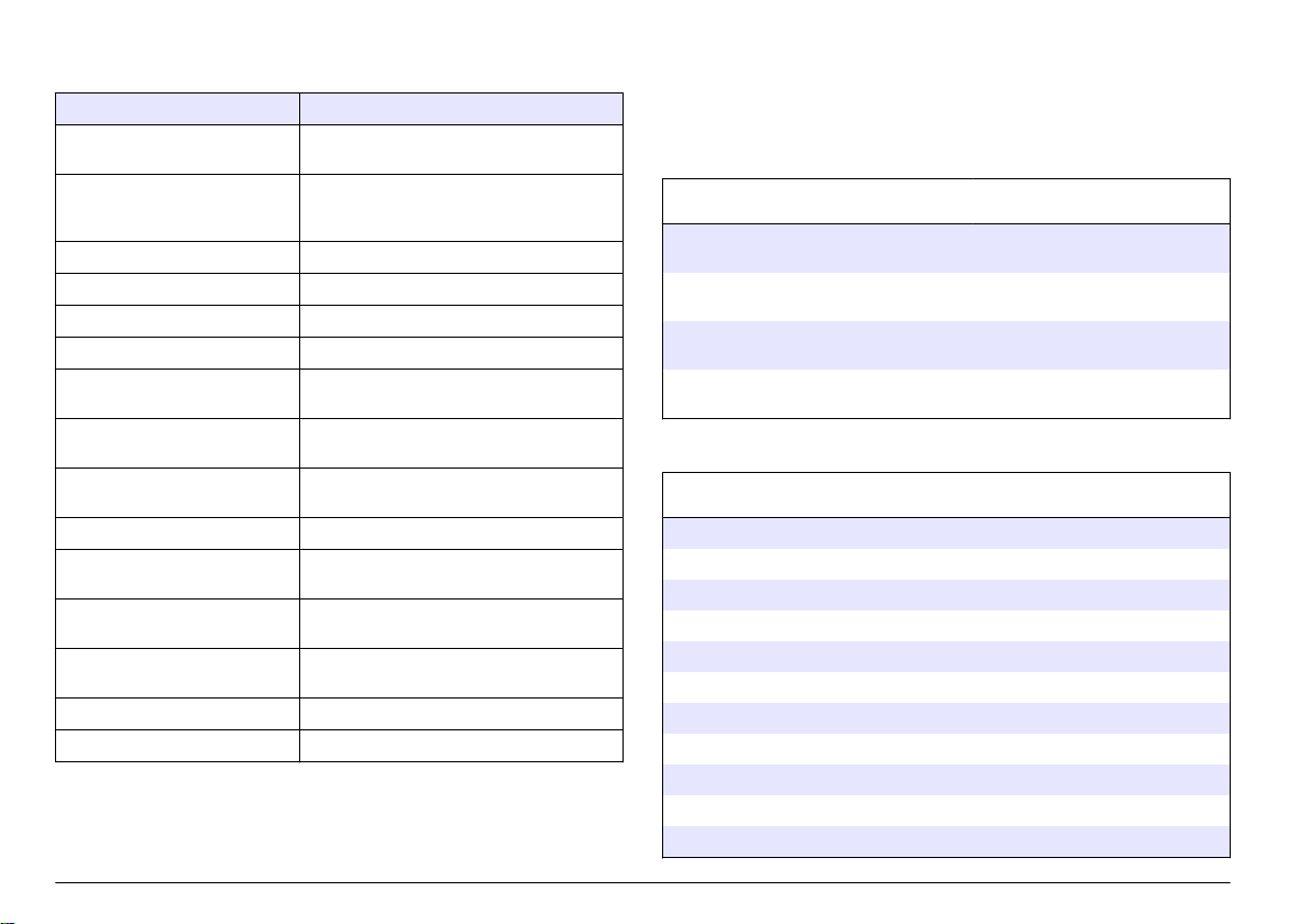
Tabla 8 Lista de eventos de los sensores de conductividad
(continúa)
Evento Descripción
CAL ALTA El valor de la calibración se encuentra por
K FUERA DE RANGO El valor de K de la constante de celda se
INESTABLE Lectura inestable durante la calibración
CAMBIO EN CONFIG real Cambio de configuración: tipo real
CAMBIO EN CONFIG texto Cambio de configuración: tipo texto
CAMBIO EN CONFIG entero Cambio de configuración: tipo entero
REST CONFIG La configuración se restableció a las
POWER ON EVENT (EVENTO
ENCENDIDO)
FALLO DE ADC Fallo del convertidor analógico-digital (fallo
BORRAR FLASH Se ha borrado la memoria flash serie externa
TEMPERATURE
(TEMPERATURA)
SAMPLE CAL START (INICIO
CAL MUESTRA)
SAMPLE CAL END (FIN CAL
MUESTRA)
INICIO CAL CERO Inicio de la calibración de cero
FIN CAL CERO Fin de la calibración de cero
encima del límite superior
encuentra fuera de rango para la calibración
actual
opciones predeterminadas
Se encendió el suministro de energía
del hardware)
Temperatura fuera de rango (-20 a 200 °C)
Inicio de la calibración de conductividad
Fin de la calibración de conductividad
Piezas de repuesto y accesorios
Nota: Las referencias de los productos pueden variar para algunas regiones de
venta. Póngase en contacto con el distribuidor correspondiente o visite la página
web de la empresa para obtener la información de contacto.
Consumibles
Descripción Cantidad Referencia
Solución de referencia para sensores de
conductividad, 100–1000 µS/cm
Solución de referencia para sensores de
conductividad, 1000–2000 µS/cm
Solución de referencia para sensores de
conductividad, 2000–150.000 µS/cm
Solución de referencia para sensores de
conductividad, 200.000–300.000 µS/cm
Repuestos y accesorios
Descripción Referencia
Cable, 5 m (16 pies) 08319=A=0005
Cable, 10 m (33 pies) 08319=A=0010
Cable, 20 m (66 pies) 08319=A=0020
Cámara de flujo directo, 6 mm (¼") Rosca NPT 08318=A=0001
Cámara de flujo directo, 19 mm (¾") Rosca NPT 08313=A=0001
Junta, EDPM, 38 mm (1.5") 429=500=380
Junta, EDPM, 51 mm, (2") 429=500=510
Montaje pulg. de diámetro, pulg. de diámetro 08394=A=0380
Montaje 2 pulg. de diámetro, pulg. de diámetro 08394=A=0510
Montaje pulg. de diámetro, pulg. de diámetro 08394=A=8150
Montaje 2 pulg. de diámetro, pulg. de diámetro 08394=A=8200
1 lt 25M3A2000-119
1 lt 25M3A2050-119
1 lt 25M3A2100-119
1 lt 25M3A2200-119
56 Español
Page 57
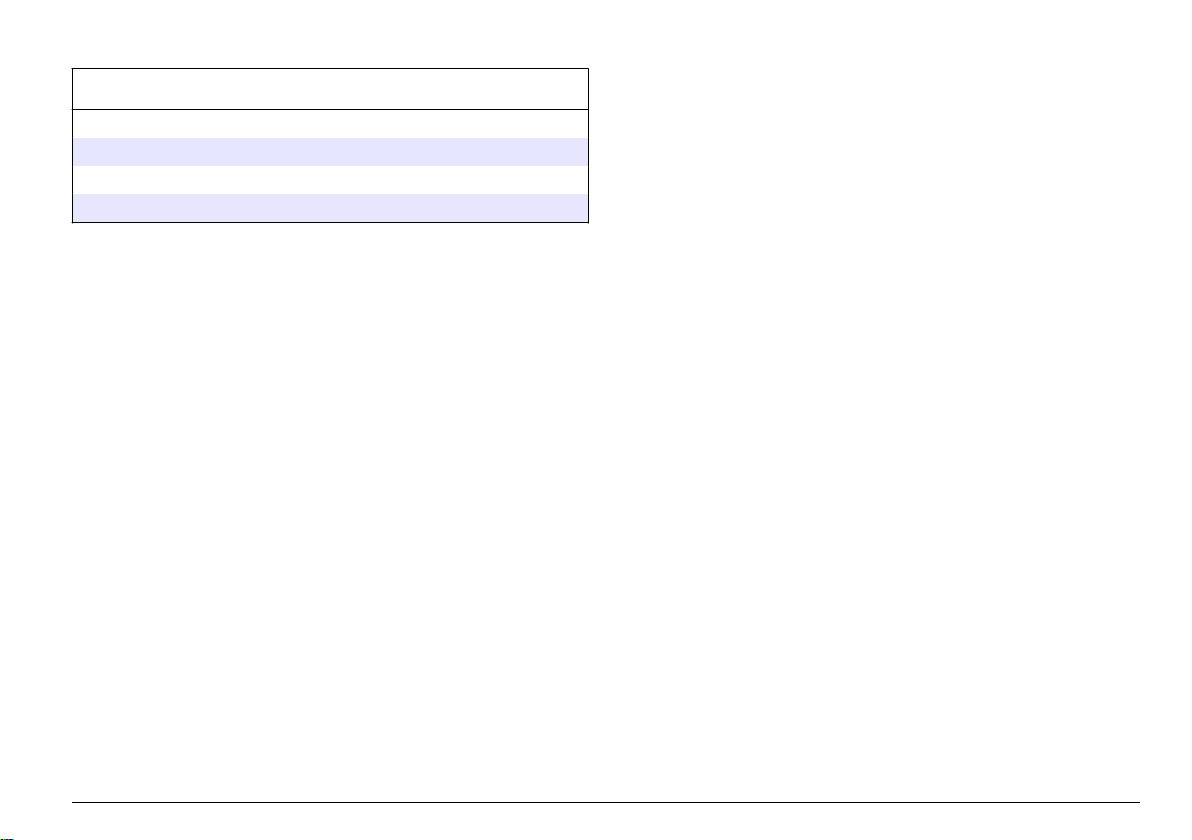
Repuestos y accesorios (continúa)
Descripción Referencia
± 2% pulg. de diámetro 08394=A=1500
pulg. de diámetro 08394=A=1511
± 2% pulg. de diámetro 08394=A=2000
pulg. de diámetro 08394=A=2011
Español 57
Page 58
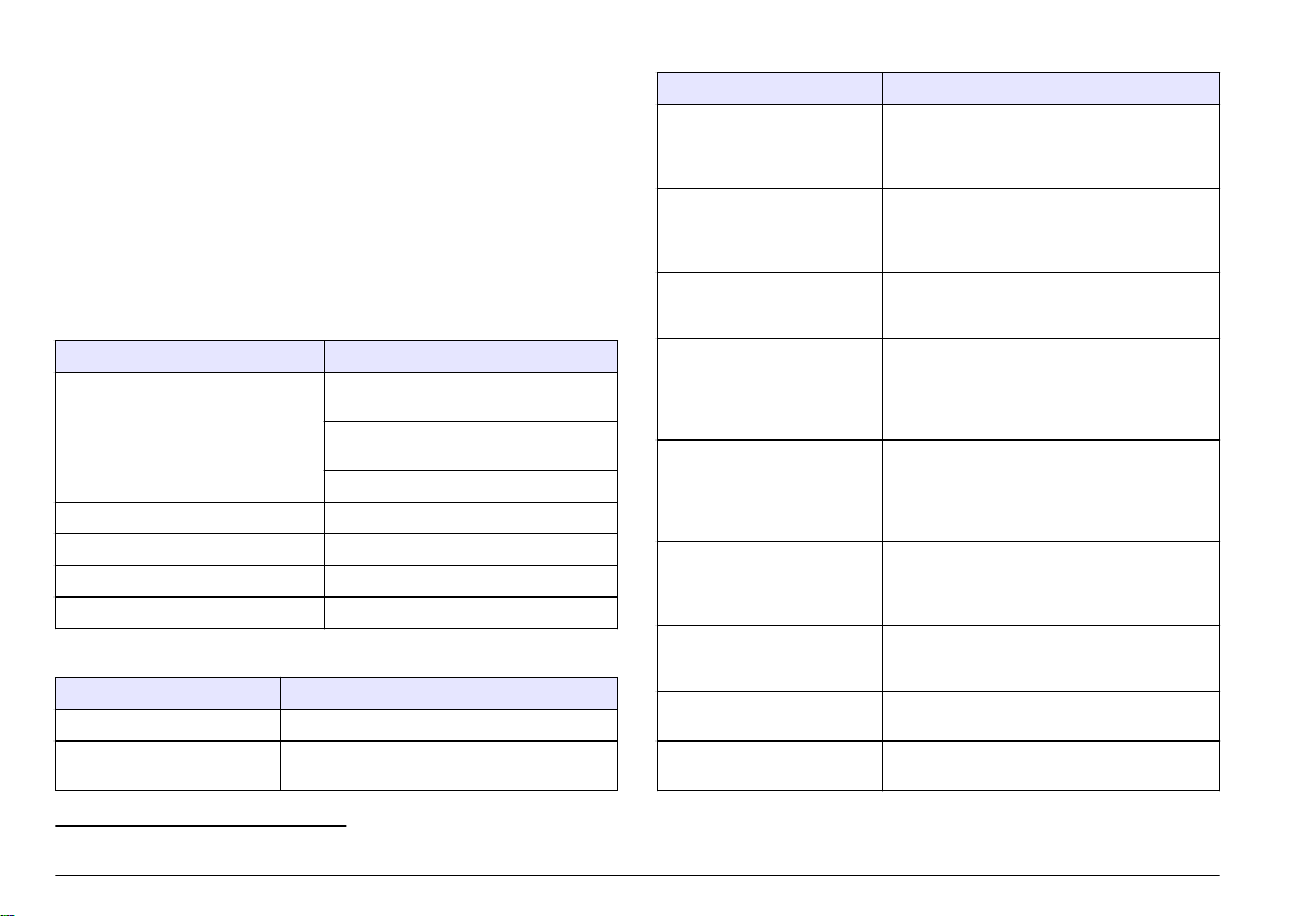
Índice
Especificações na página 58 Manutenção na página 70
Informações gerais na página 59 Solução de problemas na página 71
Instalação na página 60 Peças e acessórios de reposição
na página 75
Operação na página 65
Especificações
As especificações estão sujeitas a alterações sem aviso prévio.
Tabela 1 Especificações do módulo
Especificação Detalhes
Faixa de medição Célula de condutividade com constante
0,01: 0,01–200 µS/cm
Constante de célula 0,1:
0,1 µS–2 mS/cm
Constante de célula 1:1 µS–20 mS/cm
Tempo de resposta 0.5 segundos
Repetitividade/precisão (0–20 µS/cm) ±0.1/0.1 µS/cm
Precisão (20–200000 µS/cm) ± 0.5% da leitura
Comprimento máximo do cabo 91 m (299 pés)
Tabela 2 Especificações do sensor
Especificação Detalhes
Elemento de temperatura PT100
Cabo do sensor 4 condutores (mais 2 blindagens); 5 m
(16 pés), 10 m (33 pés) ou 20 m (66 pés)
Tabela 2 Especificações do sensor (continuação)
Especificação Detalhes
Materiais molhados — 8310 Carcaça do PSU preta, eletrodo interno 316L
Materiais molhados — 8311 Carcaça em PSU preto, eletrodo interno em
Materiais molhados — 8312 Carcaça em PSU preto, eletrodo interno em
Materiais molhados — 8315 Carcaça em aço inoxidável 316L, eletrodo
Materiais molhados — 8316 Carcaça em aço inoxidável 316L, eletrodo
Materiais molhados — 8317 Carcaça em aço inoxidável 316L, eletrodo
Materiais molhados — 8394 Carcaça em aço inoxidável, eletrodo em aço
Limite de pressão/temperatura
— 8315, 8316, 8317 ou 8394
Limite de pressão/temperatura
— 8310, 8311 ou 8312
de aço inoxidável, eletrodo externo 316L de
aço inoxidável, isolante de PSU e conector
IP65/poliéster de vidro
aço inoxidável 316L, eletrodo externo em aço
inoxidável 316L, isolante em PSU e poliéster
de vidro/conector IP65
grafite, eletrodo externo em grafite, isolante em
PSU e poliéster de vidro / conector IP65
interno em aço inoxidável 316L, eletrodo
externo em aço inoxidável 316L, isolante em
PES, o-ring em Viton® e poliéster de
vidro/conector IP65
interno em aço inoxidável 316L, eletrodo
externo em aço inoxidável 316L, isolante em
PES, o-ring em Viton e poliéster de vidro /
conector IP65
interno em grafite, eletrodo externo em grafite,
isolante em PES, o-ring em Viton e poliéster de
vidro/conector IP65
inoxidável 316L, PEEk®, vedação em EPDM e
poliéster de vidro / conector IP65
150º C (302 ºF) em 25 bar (362.5 psi)
1
125 °C (257 °F) em 10 bar (145 psi)
1
Outras marcas de ferragens de montagem e braçadeiras sanitárias podem reduzir a capacidade nominal registrada.
58 Português
Page 59

Informações gerais
Em hipótese alguma o fabricante será responsável por danos diretos,
indiretos, especiais, incidentais ou consequenciais resultantes de
qualquer defeito ou omissão neste manual. O fabricante reserva-se o
direito de fazer alterações neste manual e nos produtos aqui descritos a
qualquer momento, sem aviso ou obrigação. As edições revisadas
podem ser encontradas no site do fabricante.
Informações de segurança
A V I S O
O fabricante não é responsável por quaisquer danos devido ao uso ou aplicação
incorreta deste produto, incluindo, sem limitação, danos diretos, acidentais ou
consequenciais, e se isenta desses danos à extensão total permitida pela lei
aplicável. O usuário é unicamente responsável por identificar riscos críticos de
aplicação e por instalar os mecanismos apropriados para proteger os processos
durante um possível mau funcionamento do equipamento.
Leia todo o manual antes de tirar da embalagem, montar ou operar esse
equipamento. Preste atenção a todas as declarações de perigo e
cuidado. Caso contrário, o operador poderá sofrer ferimentos graves ou
o equipamento poderá ser danificado.
Certifique-se de que a proteção oferecida por este equipamento não
seja afetada. Não use nem instale este equipamento de nenhuma outra
forma além da especificada neste manual.
A V I S O
Indica uma situação que, se não evitada, pode causar danos ao instrumento.
Informações que necessitam de uma ênfase especial.
Avisos de precaução
Leia todas as etiquetas e rótulos fixados no instrumento. Caso não
sejam observadas, podem ocorrer lesões pessoais ou danos ao
instrumento. Um símbolo no instrumento tem sua referência no manual
com uma medida preventiva.
Este é o símbolo de alerta de segurança. Acate todas as mensagens
de segurança que seguem este símbolo a fim de evitar lesões
potenciais. Se o símbolo estiver no instrumento, consulte o manual
de instruções para obter informações sobre a operação ou
segurança.
Este símbolo identifica a presença de dispositivos sensíveis a
Descargas eletrostáticas (ESD) e indica que deve-se tomar cuidado
para evitar dano ao equipamento.
O equipamento elétrico marcado com este símbolo não pode ser
descartado em sistemas de descarte público ou doméstico europeus.
Devolva equipamentos antigos ou no final da vida útil para o
fabricante para descarte, sem custo adicional para o usuário.
Uso de informações de risco
P E R I GO
Indica uma situação potencial ou iminentemente perigosa que, se não for
evitada, resultará em morte ou lesão grave.
A D V E RT ÊN CI A
Indica uma situação potencialmente perigosa que, se não for evitada, pode
resultar em morte ou ferimento grave.
Indica uma situação potencialmente perigosa que pode resultar em ferimento
leve a moderado.
C U I D AD O
Visão geral do produto
Este sensor foi projetado para funcionar com um controlador para a
operação e armazenamento de dados. Diversos controladores podem
ser utilizados com este sensor.
O sensor está disponível em estilos diferentes. Consulte Figura 1.
Português
59
Page 60

Figura 1 Estilos de sensor
Instalação
Montagem
1 8310, k = 0.01; as aplicações
incluem água potável, tratamento
de água residual, processos
químicos e água desmineralizada e
abrandada
2 8311, k = 0,1; mesmas aplicações
do modelo 8310
3 8312, k = 1; mesmas aplicações do
modelo 8310
4 8315, k = 0.01, as aplicações
incluem monitoramento de
produção de água pura (troca
iônica e destiladores) e processo
de monitoramento de água
(condensados, ciclos de limpeza e
trocadores de calor)
5 8316, k = 0,1; mesmas aplicações
do modelo 8315
6 8317, k = 1; mesmas aplicações do
modelo 8315
7 8394, k = 0.01, estilo sanitário;
1,5 ou 2 pol. as aplicações incluem
monitoramento de água ultrapura
nas indústrias farmacêutica e de
alimentos e é adequada para
processos CIP-SIP
A D V E RT ÊN CI A
Risco de lesão corporal. A remoção do sensor de um compartimento
pressurizado pode ser perigosa. A instalação e remoção destes sensores deve
ser feita por pessoas treinadas em alta pressão e instalação de temperatura.
Sempre use hardware aprovado pelos padrões da indústria e procedimentos de
segurança quando estiver trabalhando com alta pressão e/ou sistema de
transporte de fluído de temperatura.
Para obter exemplos de sensores em aplicações diferentes, consulte
Figura 2 ou Figura 3.O sensor precisa ser calibrado antes de ser usado.
Consulte Calibrar o sensor na página 66.
Figura 2 Exemplos de montagem sanitária
60 Português
1 Conector sanitário 3 Conector fico (soldado à tubulação)
2 Vedação 4 Célula de fluxo
Page 61

Figura 3 Exemplos de montagem
1 Câmara de fluxo, PVC, 3/4 pol. NPT 2 Adaptador de montagem em T, aço inoxidável, 1/4 pol. NPT
Português 61
Page 62

Conecte o sensor ao módulo
A D V E RT ÊN CI A
Perigo potencial de eletrocussão. Desconecte sempre a energia do
instrumento quando efetuar as conexões elétricas.
A D V E RT ÊN CI A
Risco de eletrocussão. Os fios de alta voltagem para o controlador são
conduzidos por trás da barreira de alta voltagem no compartimento do
controlador. A barreira deve permanecer encaixada exceto na instalação de
módulos ou quando um técnico de instalação qualificado estiver instalando
fiação de energia, alarmes, saídas ou relés.
Dano potencial do instrumento. Componentes eletrônicos internos
delicados podem ser danificados devido à eletricidade estática,
podendo resultar em degradação do desempenho ou em uma
eventual falha.
Para instalar o módulo e conectar o sensor, consulte as etapas
ilustradas nas próximas páginas e Tabela 3. Lembre-se de conectar o
fio branco à ponta vermelha do sensor do chassi do controlador.
Observação: Se o cabo do sensor não for longo o suficiente para chegar ao
controlador, um cabo de interconexão e uma caixa da junção são necessários para
aumentar o comprimento.
A V I S O
Tabela 3 Cabeamento de sensor de condutividade de polímero
Nº do pino do conector Sinal Fio do sensor
1 Sem sinal Branco
2 — —
3 Aterramento Preto
4 — —
5 — —
6 — —
7 Temp – Preto
8 — —
9 — —
10 Temp + Azul
11 Com sinal Vermelho
12 — —
62 Português
Page 63

1 2
3 4
Português 63
Page 64

5 6
7 8
64 Português
Page 65

Operação
Navegação do usuário
Consulte a documentação do controlador para obter uma descrição do
teclado e informações de navegação.
Configurar o sensor
Use o menu Configure (Configurar) para digitar as informações de
identificação do sensor, e para alterar as opções de armazenamento e
manuseio dos dados.
1. Pressione a tecla MENU e selecione Sensor Setup (Configuração do
sensor), [Select Sensor] (Selecionar sensor), Configure (Configurar).
2. Use as teclas de seta para selecionar uma opção e pressione
ENTER. Para digitar números, caracteres ou pontuação, pressione
sem soltar as teclas de seta Para cima ou Para baixo. Pressione a
tecla de seta Para a direita para avançar para o espaço seguinte.
Opção Descrição
EDIT NAME (Editar
nome)
SENSOR S/N
(Número serial do
sensor)
SELECT MEASURE
(Selecionar medição)
DISPLAY FORMAT
(Formato de exibição)
Altera o nome que corresponde ao sensor no topo
da tela de medição. O nome é limitado a
10 caracteres com qualquer combinação de letras,
números, espaços ou pontuação.
Permite que o usuário digite o número serial do
sensor, limitado a 16 caracteres com qualquer
combinação de letras, números, espaços ou
pontuação.
Altera o parâmetro medido para condutividade
(padrão), TDS (total de sólidos dissolvidos),
salinidade ou resistividade. Quando o parâmetro é
alterado, todas as outras opções configuradas são
redefinidas para os valores padrão.
Altera o número de casas decimais que são
mostradas na tela de medição para automático
(padrão), X.XXX, XX.XX, XXX.X ou XXXX. Quando
definido para automático, o número de casas
decimais é alterado automaticamente com
alterações no valor medido.
Opção Descrição
MEAS UNITS
(Unidades de
medição)
TEMP UNITS
(Unidades de
temperatura)
T-COMPENSATION
(Compensação T)
CELL CONSTANT
(Constante de
células)
CABLE LENGTH
(Comprimento do
cabo)
TEMP ELEMENT
(Elemento da
temperatura)
Altere as unidades para a medida selecionada —
condutividade: µS/cm (padrão), mS/cm, µS/m,
mS/m ou S/m.
Define a unidade de temperatura para °C (padrão)
ou °F.
Adiciona uma correção dependente da temperatura
no valor medido—linear (padrão: 2%/°C, 25 °C),
amônia, tabela de temp (digite pontos x,y em
ordem ascendente), nenhum, água natural ou água
pura. Para aplicações especiais, pode ser digitada
uma compensação linear definida pelo usuário
(0–4%/°C, 0–200 °C). A compensação de água
natural não está disponível para TDS.
Configure a variação da constante de célula para
0,05, 0,5, 1,0 (padrão), 5,0, 10,0, polímero 0,01,
polímero 0,1 ou polímero 1.0. Após configurar a
variação, o usuário pode inserir o valor K
certificado na etiqueta no cabo de sensor. Quando
ovalor K certificado for digitado, a curva de
calibração será definida.
Define o comprimento real do cabo do sensor para
melhorar a precisão da medição (padrão: 20 pés
(padrão dos sensores de Polymetron: 5 pés)).
Define o elemento da temperatura, para a
compensação automática de temperatura, para
PT100 ou PT1000 (padrão). Após a seleção, o
usuário deverá digitar o fator T certificado no rótulo
no cabo do sensor para uma melhor precisão. Se
não for utilizado nenhum elemento, o tipo pode ser
definido para manual e um valor para a
compensação da temperatura pode ser digitado
(padrão manual: 25 °C).
Observação: Se um sensor com um elemento
PT100 ou PT1000 for ajustado para manual e o
sensor for substituído ou os dias do sensor forem
redefinidos, o TEMP ELEMENT (Elemento de
temperatura) mudará automaticamente para a
configuração padrão.
Português 65
Page 66

Opção Descrição
FILTER (FILTRO) Define uma constante de tempo para incrementar a
LOG SETUP
(Configuração do
registrador)
RESET DEFAULTS
(Restaurar padrões)
estabilidade do sinal. A constante de tempo calcula
o valor médio durante o tempo especificado—
0 (nenhum efeito, padrão) para 60 segundos
(média do valor do sinal para 60 segundos). O filtro
incrementa o tempo de resposta do sinal do sensor
para responder às alterações atuais no processo.
Define o intervalo de tempo para armazenamento
de dados no registros dos dados—5, 30 segundos,
1, 2, 5, 10, 15 (padrão), 30, 60 minutos.
Restaura o menu de configuração para os valores
padrão. Todas as configurações definidas pelo
usuário serão perdidas.
Ajustar o fator T para comprimentos de cabo não padrão
Quando o cabo do sensor for aumentado ou reduzido do comprimento
padrão de 6 m (20 pés), a resistência do cabo será alterada. Esta
alteração afeta a precisão das medições de temperatura. Para corrigir
esta diferença, calcule um fator T novo.
Observação: Este procedimento se aplica somente a sensores co um elemento
de temperatura PT1000. Os sensores com um elemento de temperatura
PT100 são menos precisos.
1. Meça a temperatura de uma solução com o sensor e com um outro
instrumento confiável, como um termômetro.
2. Registre a diferença entre a temperatura medida a partir do sensor e
a partir de uma origem independente (atual).
Por exemplo, se a temperatura atual for 50 °C e a leitura do sensor
for 53 °C, a diferença é 3 °C.
3. Multiplique esta diferença por 3,85 para obter um valor de ajuste.
Exemplo: 3 x 3,85 = 11,55.
4. Calcule um novo fator Y:
• Temperatura do sensor > atual—adicione o valor do ajuste no
fator T no cabo do sensor
• Temperatura do sensor < atual—subtraia o valor do ajuste do fator
T no cabo do sensor
5. Digite o novo fator T no menu Configure (Configurar), Temp Element
(Elemento da temperatura).
Calibrar o sensor
Acerca da calibração do sensor
Durante a calibragem, os dados não são enviados para o registro de
dados. Dessa forma, o registro de dados pode ter áreas nas quais os
dados são intermitentes.
Procedimento de calibração de zero
Use o procedimento de calibração de zero para definir o ponto zero
exclusivo do sensor de condutividade. O ponto zero precisa ser definido
antes do sensor ser calibrado pela primeira vez com uma solução de
referência ou amostra de processo.
1. Remova o sensor do processo. Limpe o sensor com uma toalha
limpa ou use ar comprimido para garantir que o sensor esteja limpo
e seco.
2. Pressione a tecla MENU e selecione Sensor Setup (Configuração do
sensor), [Selecione o sensor], Calibrate (Calibrar).
3. Pressione ENTER para selecionar Zero Cal (Calibração de zero).
4. Digite a senha, caso esta opção esteja habilitada no menu de
segurança do controlador.
5. Selecione a opção para o sinal de saída durante a calibração:
Opção Descrição
Ativo O instrumento envia para a saída o valor medido atual durante o
procedimento de calibração.
Espera O valor de saída é mantido no valor medido no início do
processo de calibração.
Transferir Um valor de saída pré-definido é enviado para a saída durante a
calibração. Consulte o manual do usuário par alterar o valor prédefinido.
6. Segure o sensor seco no ar e pressione ENTER.
66
Português
Page 67

7. Revise o resultado da calibração:
• Passou — o ponto zero está definido.
• Falhou—o valor está fora dos limites aceitos. Certifique-se de que
o sensor esteja seco e repita o procedimento de calibração de
zero. Certifique-se de que a causa não seja o cabo de extensão
digital ou excesso de ruído eletrônico.
8. Se a calibração passou, pressione ENTER para continuar.
9. Para o controlador sc100, vá para a etapa 12.
10. Digite a ID do operador, caso esta opção esteja configurada para
Yes (Sim) no menu Calibration Options (Opções de calibração).
Consulte Alterar as opções de calibração na página 70.
11. Na tela New Sensor (Novo sensor), selecione se o sensor é novo:
Opção Descrição
Sim O sensor não foi calibrado previamente com este controlador. Os
dias de operação e das curvas de calibração anteriores para o
sensor são redefinidos.
Não O sensor foi calibrado previamente com este controlador.
12. Continue para a calibração com uma solução de referência ou
amostra de processo.
Calibração com uma solução de referência
A calibração ajusta a leitura do sensor para corresponder ao valor de
uma solução de referência. Use uma solução de referência que tenha o
mesmo valor, ou superior, que as leituras de medição esperadas.
Observação: Se o sensor for calibrado pela primeira vez, certifique-se de
completar primeiro a calibração de zero.
1. Lave cuidadosamente o sensor de limpeza em água desionizada.
2. Coloque o sensor na solução de referência. Posicione o sensor de
modo que ele não toque no recipiente. Certifique-se de que a área
de detecção esteja completamente submersa na solução (Figura 4).
Agite o sensor para remover as bolhas.
Figura 4 Sensor na solução de referência
3. Aguarde até que a temperatura do sensor e da solução igualem.
Isso pode demorar até 30 minutos, ou mais, se a diferença da
temperatura entre a solução de referência e o processo for
significativa.
4. Pressione a tecla MENU e selecione Sensor Setup (Configuração do
sensor), [Selecione o sensor], Calibrate (Calibrar).
5. Selecione a calibração para o parâmetro especificado e pressione
ENTER:
• Condutividade—Cal de cond
• Cal TDS—TDS
• Salinidade—Cal de cond
• Concentração—Cal de conc ou Cal de cond
6. Digite a senha, caso esta opção esteja habilitada no menu de
segurança do controlador.
Português
67
Page 68

7. Selecione a opção para o sinal de saída durante a calibração:
Opção Descrição
Ativo O instrumento envia para a saída o valor medido atual durante o
procedimento de calibração.
Espera O valor de saída é mantido no valor medido no início do
processo de calibração.
Transferir Um valor de saída pré-definido é enviado para a saída durante a
calibração. Consulte o manual do usuário par alterar o valor prédefinido.
8. Com o sensor na solução de referência, pressione ENTER.
9. Digite a temperatura de referência da solução de referência e
pressione ENTER.
10. Digite a inclinação da solução de referência e pressione ENTER.
11. Aguarde até o valor estabilizar e pressione ENTER.
Observação: A tela pode avançar para a etapa seguinte automaticamente.
12. Use as teclas de seta para inserir o valor da solução de referência e
aperte ENTER.
13. Revise o resultado da calibração:
• Passou - o sensor está calibrado e preparado para medir
amostras. Os valores da inclinação (slope) e/ou deslocamento
(offset) são mostrados.
• Falhou - a inclinação (slope) ou deslocamento (offset) da
calibração está fora dos limites aceitos. Repita a calibração com
novas soluções de referência. Consulte Manutenção
na página 70 e Solução de problemas na página 71 para mais
informações.
14. Se a calibração passou, pressione ENTER para continuar.
15. Digite a ID do operador, caso esta opção esteja configurada para
Yes (Sim) no menu Calibration Options (Opções de calibração).
Consulte Alterar as opções de calibração na página 70.
16. Na tela New Sensor (Novo sensor), selecione se o sensor é novo:
Opção Descrição
Sim O sensor não foi calibrado previamente com este controlador. Os
dias de operação e das curvas de calibração anteriores para o
sensor são redefinidos.
Não O sensor foi calibrado previamente com este controlador.
17. Retorne o sensor ao processo e pressione ENTER.
O sinal de saída retorna ao estado ativo e o valor da amostra
medida é mostrado na tela de medição.
Observação: Se o modo de saída está definido para a espera ou
transferência, selecione o tempo de atraso para quando as saídas retornarão
ao estado ativo.
Calibração com a amostra do processo
O sensor pode permanecer no processo, ou uma amostra do processo
pode ser retirada para a calibração.
1. Pressione a tecla MENU e selecione Sensor Setup (Configuração do
sensor), [Selecione o sensor], Calibrate (Calibrar).
2. Selecione a calibração para o parâmetro especificado e pressione
ENTER:
• Condutividade—Cal de cond
• Cal TDS—TDS
• Salinidade—Cal de cond
• Concentração—Cal de conc ou Cal de cond
3. Digite a senha, caso esta opção esteja habilitada no menu de
segurança do controlador.
4. Selecione a opção para o sinal de saída durante a calibração:
Opção Descrição
Ativo O instrumento envia para a saída o valor medido atual durante o
procedimento de calibração.
68 Português
Page 69

Opção Descrição
Espera O valor de saída é mantido no valor medido no início do
processo de calibração.
Transferir Um valor de saída pré-definido é enviado para a saída durante a
calibração. Consulte o manual do usuário par alterar o valor prédefinido.
5. Com o sensor na amostra de referência, pressione ENTER.
O valor medido é mostrado.
6. Aguarde que o valor estabilize e pressione ENTER.
7. Use as teclas de seta para inserir o valor da amostra de processo e
aperte ENTER
8. Revise o resultado da calibração:
• Passou - o sensor está calibrado e preparado para medir
amostras. Os valores da inclinação (slope) e/ou deslocamento
(offset) são mostrados.
• Falhou - a inclinação (slope) ou deslocamento (offset) da
calibração está fora dos limites aceitos. Repita a calibração com
novas soluções de referência. Consulte a seção Manutenção
na página 70 e a seção Solução de problemas na página 71
para mais informações.
9. Se a calibração passou, pressione ENTER para continuar.
10. Digite a ID do operador, caso esta opção esteja configurada para
Yes (Sim) no menu Calibration Options (Opções de calibração).
Consulte Alterar as opções de calibração na página 70.
11. Na tela New Sensor (Novo sensor), selecione se o sensor é novo:
Opção Descrição
Sim O sensor não foi calibrado previamente com este controlador. Os
dias de operação e das curvas de calibração anteriores para o
sensor são redefinidos.
Não O sensor foi calibrado previamente com este controlador.
12. Retorne o sensor ao processo e pressione ENTER.
O sinal de saída retorna ao estado ativo e o valor da amostra
medida é mostrado na tela de medição.
Observação: Se o modo de saída está definido para a espera ou
transferência, selecione o tempo de atraso para quando as saídas retornarão
ao estado ativo.
Calibração de temperatura
O instrumento é calibrado na fábrica para garantir medidas precisas de
temperatura. A temperatura pode ser calibrada para melhorar a
precisão.
1. Coloque o sensor em um recipiente de água.
2. Meça a temperatura da água com um termômetro preciso ou
instrumento independente.
3. Pressione a tecla MENU e selecione Sensor Setup (Configuração do
sensor), [Selecione o sensor], Calibrate (Calibrar).
4. Selecione 1 PT Temp Cal e pressione ENTER.
5. Aguarde até o valor estabilizar e pressione ENTER.
6. Digite o valor exato e pressione ENTER.
7. Retorne o sensor ao processo e pressione ENTER.
Sair do procedimento de calibração
Se a tecla BACK (Voltar) for pressionada durante a calibração, o
usuário pode sair da calibração.
1. Pressione a tecla BACK (Voltar) durante a calibração. São exibidas
três opções:
Opção Descrição
QUIT CAL (Sair da
calibração)
Interrompe a calibração. Uma nova calibração
precisa ser reiniciada.
Português 69
Page 70
Opção Descrição
BACK TO CAL (Voltar
à calibração)
LEAVE CAL (Deixar a
calibragem)
Retornar à calibração.
Sair temporariamente da calibração. O acesso a
outros menus é permitido. Uma calibração para
um segundo sensor (se presente) pode ser
iniciada. Para retornar à calibração, pressione a
tecla MENU e selecione Sensor Setup
(Configuração do sensor), [Select Sensor]
(Selecionar sensor).
2. Use as teclas de seta para selecionar uma das opções e pressione
ENTER.
Alterar as opções de calibração
O usuário de definir um lembrete ou incluir uma ID de operador com
dados da calibragem a partir do menu CAL OPTIONS (Opções da
calibragem).
1. Pressione a tecla MENU e selecione Sensor Setup (Configuração do
sensor), [Select Sensor] (Selecionar sensor), Calibrate (Calibar), Cal
Options (Opções da calibragem).
2. Use as teclas de seta para selecionar uma opção e pressione
ENTER.
Opção Descrição
CAL REMINDER
(Lembrete da
calibração)
OP ID on CAL (ID de
opção na calibragem)
Define um lembrete para a próxima calibração
em dias, meses ou anos - Desligado (padrão),
1 dia, 7 dias, 30, 60 ou 90 dias, 6 meses ou
9 meses, 1 ou 2 anos
Inclui uma ID de operador com dados da
calibração — Sim ou Não (padrão). A ID é
digitada durante a calibração.
Redefinir as opções de calibração
As opções de calibração podem ser redefinidas para as opções padrão
de fábrica.
1. Pressione a tecla MENU e selecione Sensor Setup (Configuração do
sensor), [Select Sensor] (Selecionar sensor), Calibrate (Calibrar),
Reset Default Cal (Redefinir calibração padrão).
2. Digite a senha, caso esta opção esteja habilitada no menu de
segurança do controlador.
3. Pressione ENTER. A tela Reset Cal? (Redefinir calibração?) é
mostrada.
4. Pressione ENTER. Todas as opções de calibração serão redefinidas
para os valores padrão.
5. Digite a ID do operador, caso esta opção esteja configurada para
Yes (Sim) no menu Calibration Options (Opções de calibração).
Consulte Alterar as opções de calibração na página 70.
6. Na tela New Sensor (Novo sensor), selecione se o sensor é novo:
Opção Descrição
Sim O sensor não foi calibrado previamente com este controlador. Os
dias de operação e das curvas de calibração anteriores para o
sensor são redefinidos.
Não O sensor foi calibrado previamente com este controlador.
7. Pressione a tecla BACK (Voltar) para retornar à tela de medição.
Registradores Modbus
Uma lista de registradores Modbus está disponível para comunicação
em rede. Consulte o website do fabricante para obter mais informações.
Manutenção
70 Português
P E R I GO
Vários perigos. Somente pessoal qualificado deve realizar as tarefas
descritas nesta seção do manual.
Page 71
Limpar o sensor
Sempre calibre o sensor após os procedimentos de manutenção.
A D V E RT ÊN CI A
Risco de exposição a produtos químicos. Obedeça aos procedimentos
de segurança laboratoriais e use todos os equipamentos de proteção
individual adequados aos produtos químicos que estão sendo
manipulados. Consulte as planilhas de dados de segurança
(MSDS/SDS) atuais para verificar os protocolos de segurança.
A D V E RT ÊN CI A
Risco de lesão corporal. A remoção do sensor de um compartimento
pressurizado pode ser perigosa. A instalação e remoção destes sensores deve
ser feita por pessoas treinadas em alta pressão e instalação de temperatura.
Sempre use hardware aprovado pelos padrões da indústria e procedimentos de
segurança quando estiver trabalhando com alta pressão e/ou sistema de
transporte de fluído de temperatura.
Pré-requisito: Prepare uma solução de limpeza suave com água morna
e detergente para lavar loiça, sabão para lavagens manuais Borax ou
semelhante.
Examine periodicamente o sensor para ver se há quaisquer eventuais
detritos ou materiais depositados. Limpe o sensor quando houver
acúmulo de detritos ou quando o desempenho tiver sido prejudicado ou
avariado.
1. Use um pano limpo e macio para remover os detritos soltos da
extremidade do sensor. Enxágüe o sensor com água limpa e morna.
2. Mergulhe o sensor por 2 a 3 minutos na solução de limpeza.
3. Use uma escova macia para escovar toda a extremidade de
medição do sensor.
4. Se existirem detritos restantes, mergulhe a extremidade da medição
do sensor em uma solução de ácido diluído, como < 5% HCl durante
um máximo de 5 minutos.
5. Enxágüe o sensor com água e, então, o coloque de novo na solução
de limpeza durante 2 a 3 minutos.
6. Enxágue o sensor com água limpa.
Solução de problemas
Dados intermitentes
Durante a calibragem, os dados não são enviados para o registro de
dados. Dessa forma, o registro de dados pode ter áreas nas quais os
dados são intermitentes.
Testar o sensor de condutividade
Se uma calibração falhar, complete primeiramente os procedimentos de
manutenção em Manutenção na página 70.
1. Desconecte os fios do sensor.
2. Use um multímetro para testar a resistência entre os fios do sensor,
como mostrado na Tabela 4.
Observação: Certifique-se de que o multímetro esteja definido para a faixa
mais elevada para todas as leituras de resistência em (circuito aberto) infinitas.
Tabela 4 Medições da resistência da condutividade
Pontos de medição Resistência
Entre os fios azul e branco 1089–1106 ohms a 23–27 °C
Entre o fio vermelho e o corpo do sensor Menos que 5 ohms
Entre o fio preto e o elétrodo interior Menos que 5 ohms
Entre os fios preto e vermelho Infinito (circuito aberto)
Entre os fios preto e branco Infinito (circuito aberto)
Entre os fios vermelho e branco Infinito (circuito aberto)
Entre os fios blindados vermelho e interior Infinito (circuito aberto)
Entre os fios blindados preto e interior Infinito (circuito aberto)
Entre os fios blindados branco e interior Infinito (circuito aberto)
Entre os fios blindados exterior e interior Infinito (circuito aberto)
Português 71
Page 72
Se uma ou mais medições estiver incorreta, contate o suporte técnico.
Forneça ao suporte técnico o número de série do sensor e os valores de
resistência medidos.
Menu de teste e diagnóstico do sensor
O menu de teste e diagnóstico do sensor mostra as informações atuais
e históricas sobre o instrumento. Consulte Tabela 5. Para acessar o
menu de teste e diagnóstico do sensor, pressione a tecla MENU e
selecione Sensor Setup (Configuração do sensor), [Select Sensor]
(Selecionar sensor), DIAG/TEST.
Tabela 5 Menu Sensor DIAG/TEST (Diag/test do sensor)
Opção Descrição
SENSOR INFORMATION
(Informações do sensor)
CARD INFORMATION
(Informações da placa)
CAL DAYS (Dias de calibração) Mostra o número de dias desde a última
CAL HISTORY (Histórico de
calibração)
RESET CAL HISTORY
(Redefinir histórico da
calibração)
SENSOR SIGNALS (Sinais do
sensor)
SENSOR DAYS Mostra o número de dias que o sensor esteve
RESET SENSOR DAYS
(Redefinir dias do sensor)
Mostra o nome e o número serial que foram
digitados pelo usuário.
Mostra a versão e o número serial do módulo
do sensor.
calibração.
Mostra uma lista de calibrações e os detalhes
de cada calibração.
Uso apenas para serviço. Redefine o histórico
de calibração do sensor. Todos os dados de
calibração anteriores são perdidos.
Mostra o sinal do sensor atual e duração em
µS/cm.
em funcionamento.
Reinicia o contador de dias do sensor.
Lista de erro
Quando ocorre um erro, a leitura da tela de medição pisca e todas as
saídas são interrompidas quando especificado no menu do controlador.
Para mostrar os erros do sensor, pressione a tecla MENU e selecione
Sensor Diag (Diagnósticos do sensor), [Select Sensor] (Selecionar
sensor), Error List (Lista de erros). Uma lista dos erros possíveis é
mostrada em Tabela 6.
Tabela 6 Lista de erros para sensores de condutividade
Error (Erro) Descrição Resolução
MEAS TOO
HIGH (MEAS alto
demais)
MEAS TOO LOW
(MEAS baixo
demais)
ZERO TOO
HIGH (Zero alto
demais)
ZERO TOO LOW
(Zero baixo
demais)
TEMP TOO
HIGH
(Temperatura
alta demais)
TEMP TOO LOW A temperatura medida é
ADC FAILURE
(Falha do ADC)
O valor medido é >
2.000.000 µS/cm,
1.000.000 ppm ou
20.000 ppt
O valor medido é < 0 µS/cm,
0 ppm ou 0 ppt
O valor de calibração de
zero é > 500.000 contagens
O valor de calibração de
zero é
< –500.000 contagens
A temperatura medida é >
130 °C
<–10 °C
A conversão de analógica
para digital falhou
Certifique-se de que o sensor
esteja configurado para a
constante de células correta.
Certifique-se de que o sensor
esteja configurado para a
constante de células correta.
Certifique-se de que o sensor
esteja no ar durante a
calibração de zero, e que não
esteja localizado perto de
interferência eletromagnética
ou freqüência de rádio.
Certifique-se de que o cabo
esteja blindado por proteção
de metal.
Certifique-se de que o sensor
esteja configurado para o
elemento de temperatura
correto. Consulte Testar o
sensor de condutividade
na página 71.
Certifique-se de que o
módulo do sensor esteja
totalmente inserido no
conector do controlador.
Substitua o módulo do
sensor.
72 Português
Page 73
Tabela 6 Lista de erros para sensores de condutividade
(continuação)
Error (Erro) Descrição Resolução
SENSOR
AUSENTE
SENS OUT
RANGE (Sensor
fora do intervalo)
O sensor está faltando ou
desconectado
O sinal do sensor está fora
dos limites aceitos para a
constante da célula que é
usada (0,01 e 0,05:
100 µS/cm; 0,5:
1.000 µS/cm; 1:
2.000 µS/cm; 5:
10.000 µS/cm; 10:
200.000 µS/cm)
Examine a fiação e as
conexões do sensor e do
módulo. Certifique-se de que
o bloco terminal esteja
totalmente inserido no
módulo.
Certifique-se de que o sensor
esteja configurado para a
constante de células correta.
Lista de aviso para sensores
Um aviso não afeta a operação dos menus, relês e saídas. Um ícone de
aviso pisca e uma mensagem é mostrada no fundo da tela de medição.
Para mostrar os avisos do sensor, pressione a tecla MENU e selecione
Sensor Diag (Diagnósticos do sensor), [Select Sensor] (Selecionar
sensor), Warning List (Lista de avisos). Uma lista dos avisos possíveis é
mostrada em Tabela 7.
Tabela 7 Lista de avisos para sensores de condutividade
Advertência Descrição Resolução
ZERO TOO HIGH
(Zero alto demais)
ZERO TOO LOW
(Zero baixo demais)
O valor de calibração de
zero é >
300.000 contagens
O valor de calibração de
zero é <
-300.000 contagens
Certifique-se de que o
sensor esteja no ar durante
a calibração de zero, e que
não esteja localizado perto
de interferência
eletromagnética ou
freqüência de rádio.
Certifique-se de que o cabo
esteja blindado por proteção
de metal.
Tabela 7 Lista de avisos para sensores de condutividade
(continuação)
Advertência Descrição Resolução
TEMP TOO HIGH
(Temperatura alta
demais)
TEMP TOO LOW A temperatura medida é <
CAL OVERDUE
(Calibração
expirada)
NOT CALIBRATED
(NÃO CALIBRADO)
REPLACE
SENSOR
(SUBSTITUIR
SENSOR)
CAL IN
PROGRESS
(Calibração em
execução)
OUTPUTS ON
HOLD (Saídas em
espera)
A temperatura medida é >
100 °C
0 °C
O tempo do Cal Reminder
(Lembrete da calibração)
expirou
O sensor não foi calibrado Calibre o sensor.
O sensor esteve em
funcionamento mais de
365 dias
Uma calibração foi iniciada
mas não completada
Durante a calibração, as
saídas foram definidas
para espera durante um
período de tempo
selecionado.
Certifique-se de que o
sensor esteja configurado
para o elemento de
temperatura correto.
Calibre o sensor.
Calibre o sensor com uma
solução de referência e
redefina os dias do sensor.
Consulte Menu de teste e
diagnóstico do sensor
na página 72. Se a
calibração falhar, contate o
suporte técnico.
Retornar à calibração.
As saídas se tornarão ativas
após o período de tempo
selecionado.
Português 73
Page 74

Tabela 7 Lista de avisos para sensores de condutividade
(continuação)
Advertência Descrição Resolução
WRONG LINEAR
TC (Compensação
da temperatura
linear incorreta)
WRONG TC TABLE
(Tabela de
compensação da
temperatura
incorreta)
A compensação da
temperatura linear definida
pelo usuário está fora do
intervalo
A tabela da compensação
da temperatura definida
pelo usuário está fora do
intervalo
O valor precisa ser entre 0 e
4%/°C; 0 a 200 °C.
A temperatura está acima
ou abaixo do intervalo da
temperatura definido pela
tabela.
Lista de eventos para sensores
A lista de eventos mostra as atividades atuais como alterações da
configuração, alarmes, condições de aviso, etc. Para mostrar os
eventos, pressione a tecla MENU e selecione Sensor Diag
(Diagnósticos do sensor), [Select Sensor] (Selecionar sensor), Event
List (Lista de eventos). Uma lista dos eventos possíveis é mostrada na
Tabela 8. Os eventos anteriores são gravados no registro de eventos,
que pode ser descarregado a partir do controlador. Consulte a
documentação do controlador para saber as opções de obtenção de
dados.
Tabela 8 Lista de eventos para sensores de condutividade
Evento Descrição
CAL READY (Calibração preparada) O sensor está preparado para
CAL OK (Calibração OK) A calibração atual está OK
TIME EXPIRED (Tempo expirado) O tempo de estabilização durante a
CAL FAIL (Calibração com falha) A calibração falhou
CAL HIGH (Calibração alta) O valor da calibração é maior que o
calibração
calibração expirou
limite superior
Tabela 8 Lista de eventos para sensores de condutividade
(continuação)
Evento Descrição
K OUTRANGE (K fora do intervalo) A constante de célula K está fora do
UNSTABLE (Instável) A leitura durante a calibração estava
CHANGE IN CONFIG (Alteração na
configuração), flutuante
CHANGE IN CONFIG (Alteração na
configuração), texto
CHANGE IN CONFIG (Alteração na
configuração), inteiro
RESET CONFIG (Redefinir
configuração)
POWER ON EVENT (Evento de
ligação)
ADC FAILURE (Falha do ADC) A conversão do ADC falhou (falha do
FLASH ERASE (Flash apagada) Ocorreu o apagamento da memória
TEMPERATURE (Temperatura) A temperatura está fora do intervalo
SAMPLE CAL START (Início da
calibração com amostra)
SAMPLE CAL END (Final da
calibração da amostra)
ZERO CAL START (Início da
calibração de zero)
ZERO CAL END (Fim da calibração
de zero)
intervalo para a calibração atual
instável
A configuração foi alterada—tipo de
ponto flutuante
A configuração foi alterada—tipo de
texto
A configuração foi alterada—tipo de
valor inteiro
A configuração foi redefinida para as
opções padrão
A energia foi ligada
hardware)
flash serial externa
(-20 a 200 °C)
Início da calibração para condutividade
Fim da calibração para condutividade
Início da calibração de zero
Fim da calibração de zero
74 Português
Page 75
Peças e acessórios de reposição
Observação: Os códigos dos produtos podem variar para algumas regiões. Entre
em contato com o distribuidor apropriado ou consulte o website da empresa para
obter informações de contato.
Consumíveis
Descrição Quantidade Nº de item
Solução de referência de
condutividade, 100–1000 µS/cm
Solução de referência de
condutividade, 1000–2000 µS/cm
Solução de referência de
condutividade, 2000–150000 µS/cm
Solução de referência de
condutividade, 200000–300000 µS/cm
Peças e acessórios
Descrição Nº de item
Cabo, 5 m (16 pés) 08319=A=0005
Cabo, 10 m (33 pés) 08319=A=0010
Cabo, 20 m (66 pés) 08319=A=0020
Câmera de fluxo, 6 mm (¼ pol) Rosca NPT 08318=A=0001
Câmera de fluxo, 19 mm (¾ pol) Rosca NPT 08313=A=0001
Vedação, EDPM, 38 mm (1,5 pol) 429=500=380
Vedação, EDPM, 51 mm (2 pol) 429=500=510
Kit de montagem com vedação em EPDM, braçadeira e
tubo em aço inoxidável (h= 13 mm), 38 mm (1,5 pol.)
diâmetro interno, 50,5 mm (1,99 pol) diâmetro externo
1 L 25M3A2000-119
1 L 25M3A2050-119
1 L 25M3A2100-119
1 L 25M3A2200-119
08394=A=0380
Peças e acessórios (continuação)
Descrição Nº de item
Kit de montagem com vedação EPDM, braçadeira e tubo
em aço inoxidável (h=13 mm), 51 mm (2 pol) diâmetro
interno, 64 mm (2,52 pol) diâmetro externo
Kit de montagem com vedação EPDM, braçadeira e
câmara de fluxo, 38 mm (1,5 pol) diâmetro interno,
50,5 mm (1,99 pol) diâmetro externo
Kit de montagem com vedação EPDM, braçadeira e
câmara de aço inoxidável, 51 mm (2 pol) diâmetro interno,
64 mm (2,52 pol) diâmetro externo
O certificado de teste padrão atesta o valor real da
constante da célula em ± 2% de acordo com a ISO 7888,
ASTM D5391; 50,5 mm (1,99 pol.) de diâmetro externo
Certificado opcional de conformidade de materiais (aço
inoxidável EN 10204 3.1 B, coeficiente de rugosidade <
0,4 μm), 50,5 mm (1,99 pol.) de diâmetro externo
O certificado de teste padrão atesta o valor real da
constante da célula em ± 2% de acordo com a ISO 7888,
ASTM D5391; 64 mm (2,52 pol.) de diâmetro externo
Certificado opcional de conformidade de materiais (aço
inoxidável EN 10204 3.1 B, coeficiente de rugosidade <
0,4 μm), 50,5 mm (1,99 pol.) de diâmetro externo
08394=A=0510
08394=A=8150
08394=A=8200
08394=A=1500
08394=A=1511
08394=A=2000
08394=A=2011
Português 75
Page 76

目录
规格 第 76 维护 第 87
基本信息 第 76 故障排除 第 88
安装 第 78 更换部件与附件 第 90
操作 第 83
规格
产品规格如有变化,恕不另行通知。
表 1 模块规格
规格 详细信息
测量范围 电极常数 0.01:0.01–200 µS/cm
电极常数 0.1: 0.1 µS–2 mS/cm
电极常数 1: 1 µS–20 mS/cm
响应时间 0.5 秒
重复性/精确度 (0–20 µS/cm)
精确度 (20–200,000 µS/cm) ± 0.5%(读数)
最长电缆长度
规格 详细信息
温度元件
传感器线 4 导体(加 2 屏蔽物);5 m (16 ft)、10 m (33 ft) 或
电极材料—8310 黑色 PSU 机身、不锈钢 316L 内部电极、不锈钢 316L
PT100
20 m (66 ft),额定值为 150 °C(302 °F)
外部电极、PSU 绝缘体以及玻璃聚酯/IP65 接头
±0.1/0.1 µS/cm
91 m (299 ft)
表 2 传感器规格
表 2 传感器规格 (续)
规格 详细信息
电极材料—8311 黑色 PSU 机身、不锈钢 316L 内部电极、不锈钢 316L
电极材料—8312 黑色 PSU 机身、石墨内部电极、石墨外部电极、PSU 绝
电极材料—8315 不锈钢 316L 机身、不锈钢 316L 内部电极、不锈钢
电极材料—8316 不锈钢 316L 机身、不锈钢 316L 内部电极、不锈钢
电极材料—8317 不锈钢 316L 机身、石墨内部电极、石墨外部电极、PES
电极材料—8394 不锈钢机身、316L 电极、PEEK®、EPDM 垫片以及玻璃
温度/压力限制—
8315、8316、8317 或
1
8394
温度/压力限制—
8310、8311 或 8312
外部电极、PSU 绝缘体以及玻璃聚酯/IP65 接头
缘体以及玻璃聚酯/IP65 接头
316L 外部电极、PES 绝缘体、Viton® O 型环以及玻璃聚
酯/IP65 接头
316L 外部电极、PES 绝缘体、氟胶 O 型环以及玻璃聚
酯/IP65 接头
绝缘体、氟胶 O 型环以及玻璃聚酯/IP65 接头
聚酯/IP65 接头
150 °C (302 °F) ,压力 25 bar (362.5 psi)
125 °C (257 °F),压力 10 bar (145 psi)
基本信息
对于因本手册中的任何不足或遗漏造成的直接、间接、特别、附带或结果
性损失,制造商概不负责。制造商保留随时更改本手册和手册中描述的产
品的权利,如有更改恕不另行通知或承担有关责任。修订版可在制造商的
网站上找到。
1
其他品牌的安装硬件和卫生级管夹可能会降低认证等级。
76
中文
Page 77
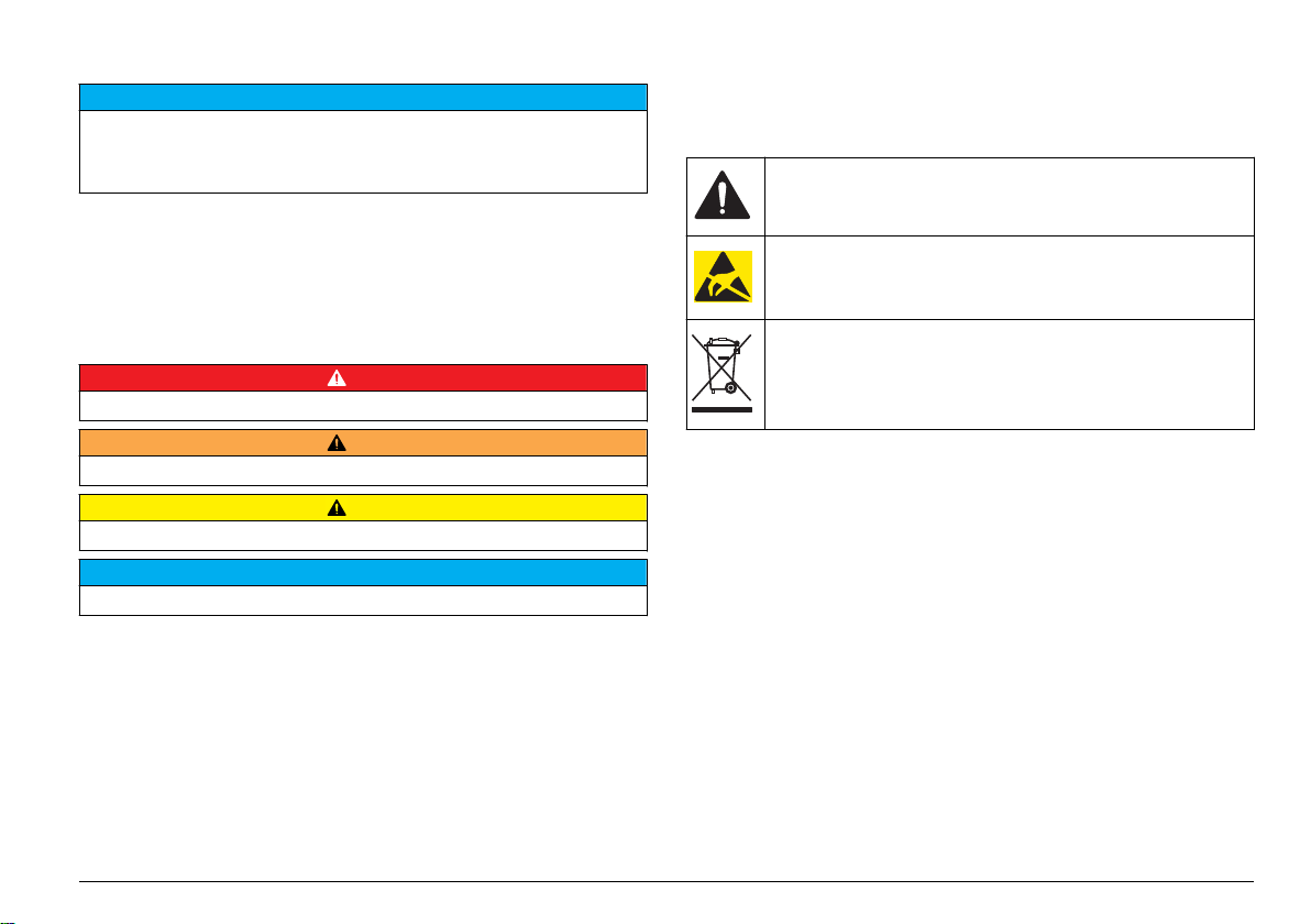
安全信息
注 意
对于误用和滥用造成的产品损坏,制造商概不负责,包括但不限于:直接、附带和
间接的损坏,并且对于适用法律允许的最大程度的损坏也不承担任何责任。用户唯
一的责任是识别重大应用风险和安装适当的系统,以在设备可能出现故障时保护整
个操作过程。
请在拆开本设备包装、安装或使用本设备前,完整阅读本手册。特别要注
意所有的危险警告和注意事项。否则,可能会对操作者造成严重的人身伤
害,或者对设备造成损坏。
确保设备提供的保护没有受损。请勿以本手册指定方式之外的其它方式使
用或安装本设备。
警告标签
请阅读贴在仪器上的所有标签和标记。 如未遵照这些安全标签的指示操
作,则可能造成人身伤害或仪器损坏。 仪器上的符号在手册中通过警告
说明参考。
这是安全警报标志。 请遵守此标志后面的所有安全信息,以避免可能
造成的伤害。 如果仪器上有此标志,则请参见仪器手册,了解操作或
安全信息。
此标志指示存在静电释放 (ESD) 敏感的设备,且必须小心谨慎以避
免设备损坏。
危险信息使用
危 险
表示潜在的或紧急的危险情况,如果不加以避免,将会导致死亡或严重伤害。
表示潜在或非常危险的情形,如不避免,可能导致严重的人身伤亡。
表示潜在的危险情形,可能导致轻度或中度人身伤害。
表明如不加以避免则会导致仪器损坏的情况。需要特别强调的信息。
警 告
警 告
注 意
标有此符号的电气设备在欧洲不能通过家庭或公共垃圾系统进行处
理。 请将老旧或报废设备寄回至制造商处进行处置,用户无需承担费
用。
产品概述
此传感器旨在配合控制器使用,用于数据收集和操作。多个控制器可与此
传感器一同使用。
有不同款式的传感器可供选择。请参阅图 1。
中文
77
Page 78
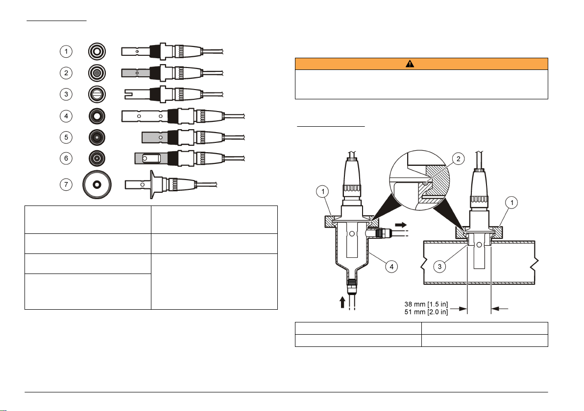
图 1 传感器款式
安装
安装方式
警 告
存在人身伤害危险。从压力容器中卸下传感器可能存在危险。这些传感器的安装和
拆卸应当由受过正规高压和高温装置培训的人员进行。在处理高压和/或高温流体
传输系统时,必须始终使用行业认可的硬件和安全规程。
有关传感器在不同应用中的示例,请参阅 图 2 或 图 3。必须在使用前校
准传感器。请参阅 校准传感器 第 84。
图 2 卫生安装示例
1 8310,k = 0.01;应用领域包括饮用
水、废水处理、化工工艺、去矿物
质水和软化水
2 8311,k = 0.1;与 8310 的应用领
域相同
3 8312,k = 1;与 8310 的应用领域相同7 8394,k = 0.01;卫生类型;1.5 或
4 8315,k = 0.01;应用领域包括纯净
水生产监控(离子交换器和蒸馏
器)及工艺用水监测(冷凝、清洗
循环和热交换器)
78
中文
5 8316,k = 0.1;与 8315 的应用领
域相同
6 8317,k = 1;与 8315 的应用领域
相同
2 英寸直径;应用领域包括制药和食
品工业中的超纯水监控,还适用于
CIP-SIP 处理
1 卫生级管夹 3 套圈(焊接至管道)
2 垫片 4 流通室
Page 79

图 3 安装示例
1 流通室 T 型安装,聚氯乙烯,¾ 英寸。NPT 2 流通室 T 型安装,不锈钢,1/4 英寸。NPT
中文
79
Page 80

将传感器连接到模块
警 告
可能存在电击致命危险。进行任何电气连接时,请务必断开仪器的电
源。
警 告
存在电击致命危险。控制器的高压线引至控制器外壳内高压防护层的后面。除非安
装了模块或合格的安装技术人员布线电源、继电器或模拟和网卡,否则必须配备防
护层。
可能导致仪器损坏。静电会损害精密的内部电子组件,从而导致仪器性
能降低或最终出现故障。
要安装模块及连接传感器,请参阅以下各页所示的步骤以及表 3。请务必
使用带红色条纹的白色电线将传感器连接到控制器底座。
注: 如果传感器的电缆长度不足以连接到控制器,需使用连接线和接线盒加以延
长。
表 3 Polymetron 电导率传感器接线
接头引脚编号 信号 传感器电线
1
2 — —
注 意
输出 白色
表 3 Polymetron 电导率传感器接线 (续)
接头引脚编号 信号 传感器电线
3
4 — —
5 — —
6 — —
7
8 — —
9 — —
10
11
12 — —
接地 黑色
Temp(温度)– 黑色
TEMP(温度)+ 蓝色
输入 红色
80
中文
Page 81

1 2
3 4
中文
81
Page 82
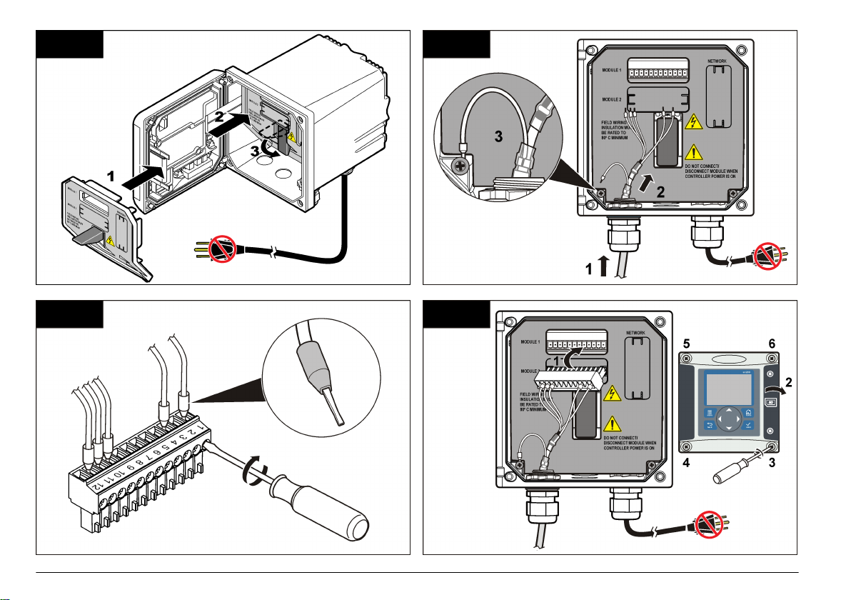
5 6
7 8
82
中文
Page 83

操作
用户导航
有关键盘说明和导航信息,请参阅控制器文档。
配置传感器
使用“Configure(配置)”菜单输入传感器的识别信息,或更改数据处理和
存储的选项。
1. 按 MENU 键,然后选择“Sensor Setup(传感器设置)”、[“Select
Sensor(选择传感器)”]、“Configure(配置)”。
2. 使用方向键选择一个选项,然后按 ENTER。要输入数字、字符或标点
符号,则按住向上或向下方向键。按右方向键可移至下一空间。
选项 说明
EDIT NAME(编辑名称)更改测量屏幕顶端上传感器对应的名称。名称限于字
SENSOR S/N(传感器
序列号)
SELECT MEASURE
(选择测量)
DISPLAY FORMAT
(显示格式)
MEAS UNITS(测量单位)更改所选测量—电导率的单位:µS/cm(默认)、
TEMP UNITS(温度单位)将温度单位设为 °C(默认值)或 °F。
T-COMPENSATION
(温度补偿)
母、数字、空格或标点任何组合的 10 个字符。
允许用户输入传感器序列号,限于字母、数字、空格
或标点任何组合的 16 个字符。
将测量参数更改为电导率(默认值)、TDS(total
dissolved solids,总溶解固体)、盐度或电阻率。当
参数更改时,所有其他配置设置重设为默认值。
将测量屏幕上显示的小数位数更改为“自动”(默认
值)、X.XXX、XX.XX、XXX.X 或 XXXX。当设为
“自动”时,小数位数会随测量值的变化自动改变。
mS/cm、µS/m、mS/m 或 S/m
将温度相关的校正添加至测量值—线性(默认值:
2.0%/°C,25 °C)、氨水、温度表(按升序输入 x,y
点)、无、天然水或纯水。对于特定应用,可输入用
户定义的线性补偿(0–4%/°C,0–200 °C)。纯水
补偿不适用于 TDS。
选项 说明
CELL CONSTANT
(电极常数)
CABLE LENGTH(电
缆长度)
TEMP ELEMENT(温
度元件)
过滤器 设置时间常数,以增加信号的稳定性。时间常数可计
LOG SETUP(日志设置)设置数据日志中数据存储的时间间隔—5 秒、
RESET DEFAULTS
(重设默认值)
将电极常数范围设置为 0.05、0.5、1.0(默认)、
5.0、10.0、0.01 Polymetron、0.1 Polymetron 或
1.0 Polymetron。选定范围后,用户可输入传感器电
缆标签上经认证的 K 值。输入经认证的 K 值后,即
可定义校准曲线。
设置传感器电缆的实际长度可改善测量精度(默认
值:20 ft(Polymetron 传感器默认值:5 ft))。
将自动温度补偿的温度元件设为 PT100 或 PT1000
(默认值)。选择后,用户应输入传感器电缆标签上
经认证的温度系数,以确保最佳的准确度。如果没有
使用元件,该类型可设为手动,且可输入温度补偿值
(手动默认值:25 °C)。
注: 如果将采用
置为手动,并将其更换,或重设传感器天数,则
TEMP ELEMENT
置。
算特定时间内的平均值—0(无影响,默认值)至
60 秒(60 秒的信号平均值)。过滤器将增加传感器
信号响应过程中实际变化的时间。
30 秒、1 分钟、2 分钟、5 分钟、10 分钟、15 分钟
(默认值)、30 分钟和 60 分钟。
将配置菜单设为默认设置。所有用户定义的设置都将
丢失。
PT100 或 PT1000
(温度元件)会自动更改为默认设
元件的传感器设
调整非标准电缆长度的温度系数
当传感器电缆长于或短于 6 m (20 ft) 时,电缆的电阻发生变化。此变化会
降低温度测量的准确度。要校正此差异,应计算新的温度系数。
注: 此过程仅适用于带
准确度较低。
1. 分别使用传感器和独立、可靠的仪器(如温度计)测量溶液的温度。
2. 记录传感器测量的温度与独立源测量的温度(实际温度)之间的差
值。
例如,如果实际温度为
3 °C
。
PT1000
温度元件的传感器。采用
50 °C
,而传感器读数为
PT100
温度元件的传感器
53 °C
,则差值为
中文
83
Page 84

3. 将此差值乘以 3.85,即得到调整值。
例如:
3 x 3.85 = 11.55
。
4. 计算新的温度系数:
• 传感器温度大于实际温度—将调整值与传感器电缆的温度系数相加
• 传感器温度小于实际温度—将传感器电缆的温度系数减去调整值
5. 在“Configure(配置)”→“Temp Element(温度元件)”菜单中输入新
温度系数。
校准传感器
关于传感器校准
校准过程中,不会发送数据到数据记录。因此,数据记录可以有间歇数据
区域。
零点校准程序
使用零点校准程序定义电导率传感器唯一的零点。必须先定义零点,然后
再使用参考溶液或过程试样首次校准传感器。
1. 从过程溶液中取出传感器。用干净的毛巾擦净传感器,或用压缩空气
吹扫,以确保传感器清洁、干燥。
2. 按 MENU 键,然后选择“Sensor Setup(传感器设置)”、“Select
Sensor(选择传感器)”、“Calibrate(校准)”。
3. 按 ENTER 选择“Zero Cal(零点校准)”。
4. 如果控制器安全菜单中已启用密码,则须输入密码。
5. 在校准过程中选择输出信号的选项:
选项 说明
ACTIVE(有效) 仪器在校准过程中发送当前测量的输出值。
Hold(保持) 传感器输出值在校准过程中保持为当前测量值。
Transfer(转换) 在校准过程中发送预设的输出值。要更改预设值,请参阅
6. 将弄干的传感器放在空气中,然后按 ENTER。
7. 查看校准结果:
• 成功—设置零点。
控制器用户手册。
• 失败—值超出接受的限值。确保传感器已干,并重复零点校准程
序。确保不是数字延长电缆或大量电噪声所致。
8. 如果校准成功,按 ENTER 继续。
9. 对于 sc100 控制器,跳到第 12 步。
10. 如果在 Calibration Options(校准选项)菜单中操作员 ID 选项设为
Yes(是),则输入操作员 ID。请参阅更改校准选项 第 87。
11. 在 New Sensor(新传感器)屏幕上,选择传感器是否为新:
选项 说明
是 传感器之前未通过此控制器校准。传感器的运行天数和之前的校准曲线
将重设。
否 传感器之前已通过此控制器校准。
12. 继续使用参考溶液或过程试样校准。
使用参考溶液校准
校准调整传感器读数,以匹配参考溶液的值。使用与预期测量读数相同或
比预期测量读数更大的值的参考溶液。
注: 如果首次校准传感器,务必首先完成零点校准。
1. 用去离子水彻底冲洗未用过的传感器。
2. 将传感器放入参考溶液中。托住传感器,以便它不会接触容器。确保
传感区域完全浸入溶液中(图 4)。搅动传感器,以去除气泡。
84
中文
Page 85

图 4 传感器放入参考溶液
3. 等待传感器与溶液温度相等。如果过程溶液与参考溶液的温差很大,
此过程可能需要 30 分钟或以上。
4. 按 MENU 键,然后选择“Sensor Setup(传感器设置)”、“Select
Sensor(选择传感器)”、“Calibrate(校准)”。
5. 选择校准特定参数,然后按 ENTER:
• Conductivity(电导率)—电导率校准
• TDS—TDS 校准
• Salinity(盐度)—电导率校准
• Concentration(浓度)—浓度校准或电导率校准
6. 如果控制器安全菜单中已启用密码,则须输入密码。
7. 在校准过程中选择输出信号的选项:
选项 说明
ACTIVE(有效) 仪器在校准过程中发送当前测量的输出值。
Hold(保持) 传感器输出值在校准过程中保持为当前测量值。
Transfer(转换) 在校准过程中发送预设的输出值。要更改预设值,请参阅
控制器用户手册。
8. 将传感器放入参考溶液中,然后按 ENTER。
9. 输入参考溶液的参考温度,然后按 ENTER。
10. 输入参考溶液的斜率,然后按 ENTER。
11. 等待值稳定后按 ENTER.
注: 屏幕可能自动进入下一步。
12. 使用箭头键输入参考溶液的值,然后按 ENTER 键。
13. 查看校准结果:
• 成功—传感器已经校准并准备测量试样。将显示斜率和/或偏移值。
• 失败—校准斜率或偏移值超出接受的限值。用新的参考溶液重复校
准。有关详情,请参阅维护 第 87 和故障排除 第 88。
14. 如果校准成功,按 ENTER 继续。
15. 如果在 Calibration Options(校准选项)菜单中操作员 ID 选项设为
Yes(是),则输入操作员 ID。请参阅更改校准选项 第 87。
16. 在 New Sensor(新传感器)屏幕上,选择传感器是否为新:
选项 说明
是 传感器之前未通过此控制器校准。传感器的运行天数和之前的校准曲线
将重设。
否 传感器之前已通过此控制器校准。
17. 将传感器重新投入应用,然后按 ENTER。
输出信号恢复激活状态,且测量屏幕上将显示测量的试样值。
注: 如果输出模式设为保持或转换,则选择输出恢复激活状态的延迟时间。
使用过程试样校准
传感器可以保留在过程试样中,或可倒出一部分过程试样以备校准。
1. 按 MENU 键,然后选择“Sensor Setup(传感器设置)”、“Select
Sensor(选择传感器)”、“Calibrate(校准)”。
2. 选择校准特定参数,然后按 ENTER:
• Conductivity(电导率)—电导率校准
• TDS—TDS 校准
• Salinity(盐度)—电导率校准
• Concentration(浓度)—浓度校准或电导率校准
中文
85
Page 86

3. 如果控制器安全菜单中已启用密码,则须输入密码。
4. 在校准过程中选择输出信号的选项:
选项 说明
ACTIVE(有效) 仪器在校准过程中发送当前测量的输出值。
Hold(保持) 传感器输出值在校准过程中保持为当前测量值。
Transfer(转换) 在校准过程中发送预设的输出值。要更改预设值,请参阅
控制器用户手册。
5. 将传感器放入过程试样中,然后按 ENTER。
显示测量值。
6. 等待值稳定后按 ENTER。
7. 使用箭头键输入过程试样的值,然后按 ENTER 键。
8. 查看校准结果:
• 成功—传感器已经校准并准备测量试样。将显示斜率和/或偏移值。
• 失败—校准斜率或偏移值超出接受的限值。用新的参考溶液重复校
准。有关详情,请参阅维护 第 87 和故障排除 第 88。
9. 如果校准成功,按 ENTER 继续。
10. 如果在 Calibration Options(校准选项)菜单中操作员 ID 选项设为
Yes(是),则输入操作员 ID。请参阅更改校准选项 第 87。
11. 在 New Sensor(新传感器)屏幕上,选择传感器是否为新:
选项 说明
是 传感器之前未通过此控制器校准。传感器的运行天数和之前的校准曲线
将重设。
否 传感器之前已通过此控制器校准。
12. 将传感器重新投入应用,然后按 ENTER。
输出信号恢复激活状态,且测量屏幕上将显示测量的试样值。
注: 如果输出模式设为保持或转换,则选择输出恢复激活状态的延迟时间。
2. 使用精确的温度计或单独的仪器测量水温。
3. 按 MENU 键,然后选择“Sensor Setup(传感器设置)”、“Select
Sensor(选择传感器)”、“Calibrate(校准)”。
4. 选择 1 PT Temp Cal(1 PT 温度校准)并按 ENTER。
5. 等待值稳定后按 ENTER.
6. 输入精确值,再按 ENTER。
7. 将传感器重新投入应用,然后按 ENTER。
退出校准过程
如果在校准过程中按下 BACK 键,用户可退出校准。
1. 在校准过程中按下 BACK 键。将显示三个选项:
选项 说明
QUIT CAL(退出校准)停止校准。新校准必须从头开始。
BACK TO CAL(后
退到校准)
LEAVE CAL(离开校准)暂时退出校准。可访问其他菜单。可开始另一个传感
2. 使用方向键选择其中一个选项,然后按 ENTER。
返回到校准
器(如有)的校准。要返回到校准,按 MENU 键,然
后选择“Sensor Setup(传感器设置)”、[“Select
Sensor(选择传感器)”]。
温度校准
仪器出厂时已经校准为精确的温度测量值。校准温度可以提高精度。
1. 将传感器放入一个含水容器中。
86
中文
Page 87
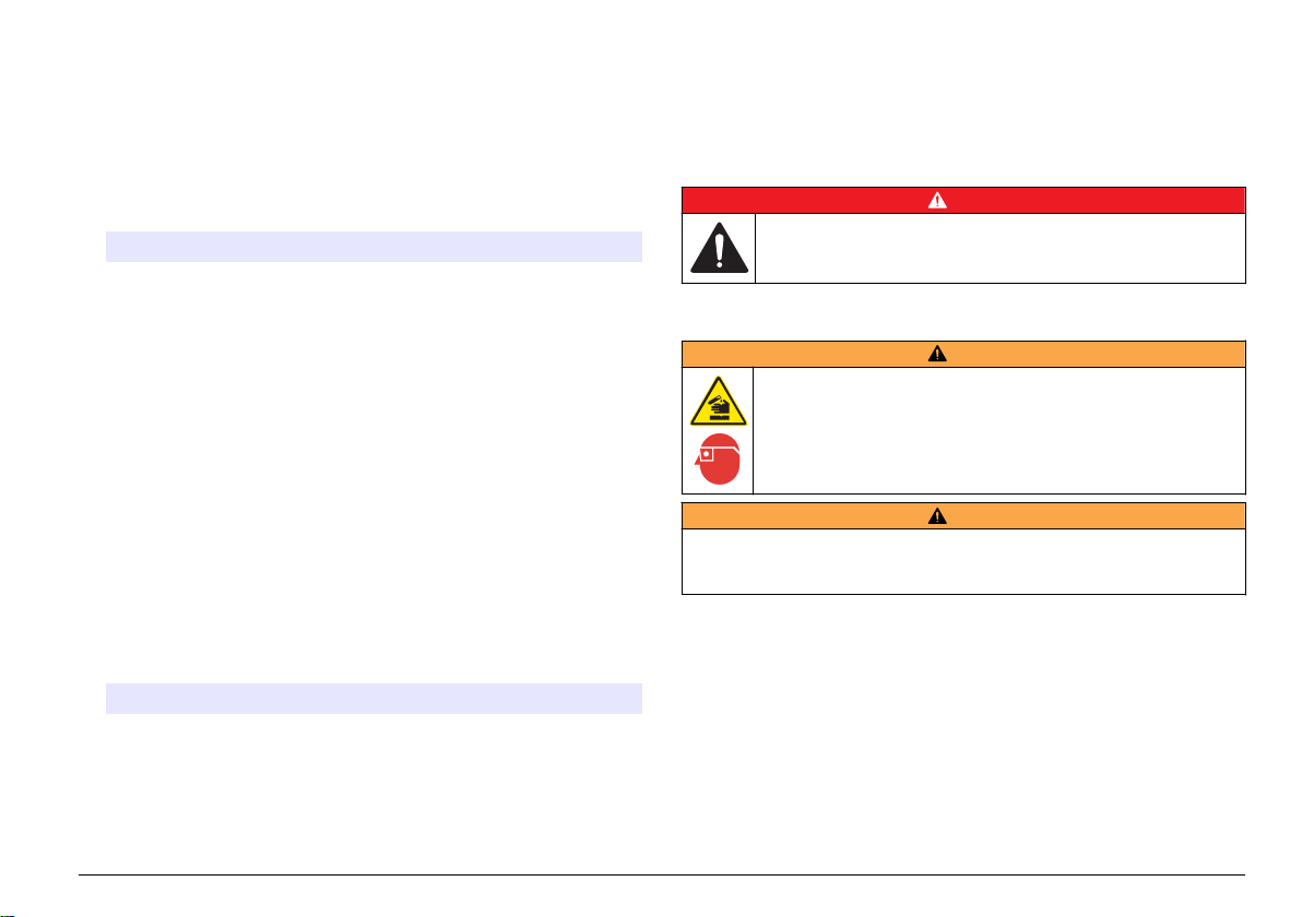
更改校准选项
用户可通过“CAL OPTIONS(校准选项)”菜单设置提示或包括操作员 ID
和校准数据。
1. 按 MENU 键,然后选择“Sensor Setup(传感器设置)”、[“Select
Sensor(选择传感器)”]、“Calibrate(校准)”、“Cal Options(校准
选项)”。
2. 使用方向键选择一个选项,然后按 ENTER。
选项 说明
CAL REMINDER(校准
提示)
OP ID on CAL(校准操
作员 ID)
设置按天、按月或按年的下次校准提示—关(默认
值)、1 天、7 天、30 天、60 天或 90 天、6 个月
或 9 个月、1 年或 2 年
包括操作员 ID 和校准数据 - Yes(是)或 No
(否)(默认值)。在校准过程中输入 ID。
Modbus 寄存器
Modbus 寄存器列表可供网络通信使用。请参阅制造商的网站了解更多信
息。
维护
危 险
多种危险。只有合规的专业人员才能从事文档中本部分所述的任务。
清洗传感器
警 告
重设校准选项
校准选项可重设为工厂默认选项。
1. 按 MENU 键,然后选择“Sensor Setup(传感器设置)”、[“Select
Sensor(选择传感器)”]、“Calibrate(校准)”、“Reset Default Cal
(重设默认校准)”。
2. 如果控制器安全菜单中已启用密码,则须输入密码。
3. 按 ENTER。出现“The Reset Cal?”(是否重置校准?)屏幕。
4. 按 ENTER。所有校准选项均设为默认值。
5. 如果在 Calibration Options(校准选项)菜单中操作员 ID 选项设为
Yes(是),则输入操作员 ID。请参阅更改校准选项 第 87。
6. 在 New Sensor(新传感器)屏幕上,选择传感器是否为新:
选项 说明
是 传感器之前未通过此控制器校准。传感器的运行天数和之前的校准曲线
将重设。
否 传感器之前已通过此控制器校准。
7. 按 BACK 键返回到测量屏幕。
化学品暴露风险。遵守实验室安全规程,穿戴适用于所处理化学品的所
有个人防护装备。有关安全规程,请参阅当前安全数据表
(MSDS/SDS)。
警 告
存在人身伤害危险。从压力容器中卸下传感器可能存在危险。这些传感器的安装和
拆卸应当由受过正规高压和高温装置培训的人员进行。在处理高压和/或高温流体
传输系统时,必须始终使用行业认可的硬件和安全规程。
事先准备:准备温和的肥皂溶液、温水及餐具洗涤剂、硼砂洗手液或类似
的脂肪酸盐。
定期检查传感器是否存在污垢和沉淀物。当形成沉淀物或性能降低时,清
洗传感器。
1. 使用干净的软布清除传感器端壁上的污垢。使用干净的温水冲洗传感
器。
2. 将传感器浸入肥皂溶液中 2 到 3 分钟。
3. 使用软毛刷刷洗传感器的整个测量端。
4. 如果仍有污垢,将传感器的测量端浸入稀酸溶液(如 < 5% HCl)不超
过 5 分钟。
中文
87
Page 88
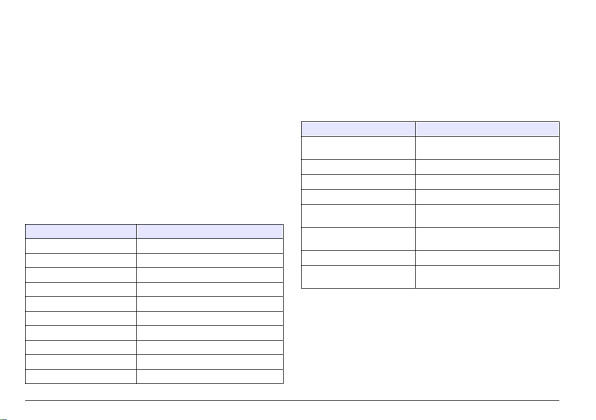
5. 用水冲洗传感器,然后将传感器放回肥皂溶液中 2 到 3 分钟。
6. 使用净水冲洗传感器。
如果一个或多个测量不正确,请致电技术支持部门。请向技术支持人员提
供传感器序列号和所测电阻值。
维护操作完成后应始终校准传感器。
故障排除
间歇数据
校准过程中,不会发送数据到数据记录。因此,数据记录可以有间歇数据
区域。
测试电导率传感器
如果校准失败,首先完成维护 第 87 中的维护步骤。
1. 断开传感器电线。
2. 使用欧姆计测试传感器电线之间的电阻(如表 4 所示)。
注: 欧姆计务必设为其所有无穷(断路)电阻读数的最高范围。
表 4 电导率电阻测量
测量点 电阻
蓝色与白色电线之间 在 23 至 27 °C 时为 1089 至 1106 欧姆
红色电线与传感器主体之间 小于 5 欧姆
黑色电线与内部电极之间 小于 5 欧姆
黑色电线与红色电线之间 无穷(断路)
黑色电线与白色电线之间 无穷(断路)
红色电线与白色电线之间 无穷(断路)
红色电线与内部屏蔽电线之间 无穷(断路)
黑色电线与内部屏蔽电线之间 无穷(断路)
白色电线与内部屏蔽电线之间 无穷(断路)
外部与内部屏蔽电线之间 无穷(断路)
传感器诊断和测试菜单
传感器诊断和测试菜单显示仪器的当前和历史记录信息。请参阅 表 5。要
访问传感器诊断和测试菜单,按 MENU 键,然后选择“Sensor Setup(传
感器设置)”、“Select Sensor(选择传感器)”、“DIAG/TEST(诊断/测
试)”。
表 5 传感器诊断/测试菜单
选项 说明
SENSOR INFORMATION(传感
器信息)
CARD INFORMATION(卡信息) 显示传感器控制器的版本和序列号。
CAL DAYS(校准天数) 显示自上次校准以来的天数。
CAL HISTORY(校准历史记录) 显示校准列表及每次校准的详细信息。
RESET CAL HISTORY(重设校准
历史记录)
SENSOR SIGNALS(传感器信号)显示当前传感器信号和范围(单位:
SENSOR DAYS(传感器天数) 显示传感器已运行的天数。
RESET SENSOR DAYS(重设传
感器天数)
显示用户输入的名称和序列号。
仅维修使用。重设传感器的校准历史记录。
之前所有的校准数据将丢失。
µS/cm)。
重设传感器天数计数器。
错误列表
发生错误时,测量屏幕上的读数将会闪烁,在控制器菜单中指定的所有输
出将被暂停。要显示传感器错误,按 MENU 键,然后选择“Sensor Diag
88
中文
Page 89

(传感器诊断)”、“Select Sensor(选择传感器)”、“Error List(错误列
表)”。可能出现的错误列表如 表 6 所示。
表 6 电导率传感器的错误列表
错误 说明 分辨率
MEAS TOO
HIGH(测量值太
高)
MEAS TOO
LOW(测量值太
低)
ZERO TOO
HIGH(0 值太
高)
ZERO TOO
LOW(0 值太
低)
TEMP TOO
HIGH(温度太
高)
TEMP TOO
LOW(温度太
低)
ADC FAILURE
(A/D 转换失
败)
SENSOR
MISSING(传感
器丢失)
SENS OUT
RANGE(传感器
信号超出范围)
测量值大于
2,000,000 µS/cm、
1,000,000 ppm 或 20,000 ppt
测量值小于 0 µS/cm、0 ppm
或 0 ppt
零点校准值大于 500,000 点数确保传感器在零点校准时置于
零点校准值小于 –500,000 点
数
测量的温度值高于 130 °C 确保已为传感器配置了正确的
测量的温度值低于 –10 °C
模拟与数字转换失败 确保传感器控制器完全插入控
传感器丢失或断开 检查传感器和控制器的接线及
传感器信号超出所用电极常数
的接受限值(0.01 和 0.05:
100 µS/cm;0.5:
1000 µS/cm;1:
2000 µS/cm;5:
10,000 µS/cm;10:
200,000 µS/cm)
确保为传感器配置了正确的电
极常数。
确保为传感器配置了正确的电
极常数。
空气中,且没有置于射频或电
磁干扰的附近。确保电缆已由
金属导管屏蔽。
温度元件。请参阅测试电导率
传感器 第 88。
制器接头。更换传感器控制
器。
连接。确保接线板完全插入了
控制器。
确保为传感器配置了正确的电
极常数。
传感器警告列表
警告不会影响对菜单、继电器和输出的操作。警告图标闪烁,且消息将显
示在测量屏幕的底部。要显示传感器警告,按 MENU 键,然后选择
“Sensor Diag(传感器诊断)”、“Select Sensor(选择传感器)”、
“Warning List(警告列表)”。可能的警告列表如 表 7 所示。
表 7 电导率传感器的警告列表
警告 说明 分辨率
ZERO TOO HIGH
(0 值太高)
ZERO TOO LOW
(0 值太低)
TEMP TOO HIGH
(温度太高)
TEMP TOO LOW(温
度太低)
CAL OVERDUE(校
准过期)
NOT CALIBRATED
(未校准)
REPLACE SENSOR
(更换传感器)
CAL IN PROGRESS
(校准进行中)
OUTPUTS ON HOLD
(输出保持)
零点校准值大于
300,000 点数
零点校准值小
于 –300,000 点数
测量的温度值高于 100 °C 确保已为传感器配置了正确
测量的温度值低于 0 °C
“校准提示”时间到期 校准传感器。
传感器尚未校准 校准传感器。
传感器运行已超过 365 天 使用参考溶液校准传感器,
校准已开始但尚未完成 返回到校准。
在校准过程中,将输出设
为在所选时间保持。
确保传感器在零点校准时置
于空气中,且没有置于射频
或电磁干扰的附近。确保电
缆已由金属导管屏蔽。
的温度元件。
并重设传感器天数。请参阅
传感器诊断和测试菜单
第 88。如果校准失败,请致
电技术支持部门。
输入将在所选时段过后激
活。
中文
89
Page 90

表 7 电导率传感器的警告列表 (续)
警告 说明 分辨率
WRONG LINEAR TC
(错误线性温度补
偿)
WRONG TC TABLE
(错误温度补偿表)
用户定义的线性温度补偿
超出范围
用户定义的温度补偿表超
出范围
该值必须介于 0 至 4%/°C 之
间;0 至 200 °C。
温度高于或低于表格定义的
温度范围。
传感器的事件列表
事件列表显示配置更改、警报和警告情况等当前活动。要显示事件,按
MENU 键,然后选择“Sensor Diag(传感器诊断)”、“Select Sensor(选
择传感器)”、“Event List(事件列表)”。可能发生的事件列表如 表 8 所
示。先前的事件记录在事件日志中,并可从控制器中下载。数据检索选项
请见控制器文档。
表 8 电导率传感器的事件列表
事件 说明
CAL READY(校准就绪) 传感器校准就绪
CAL OK(校准成功) 当前校准成功
TIME EXPIRED(时间截止) 校准过程中的稳定时间截止
CAL FAIL(校准失败) 校准失败
CAL HIGH(校准高) 校准值高于上限
K OUTRANGE(K 超出范围) 电极常数 K 超出当前校准的范围
UNSTABLE(不稳定) 校准期间读数不稳定
CHANGE IN CONFIG float(配置更改(浮
点))
CHANGE IN CONFIG text(配置更改(文
本))
CHANGE IN CONFIG int(配置更改(整
数))
配置已更改—浮点类型
配置已更改—文本类型
配置已更改—整数值类型
表 8 电导率传感器的事件列表 (续)
事件 说明
RESET CONFIG(复位组态) 将配置重设为默认选项。
POWER ON EVENT(开机事件) 打开电源
ADC FAILURE(A/D 转换失败) A/D 转换失败(硬件故障)
FLASH ERASE(擦除闪存) 发生外部串行闪存擦除
TEMPERATURE(温度) (温度超出范围(-20 至 200 °C)
SAMPLE CAL START(试样校准开始) 电导率校准开始
SAMPLE CAL END(试样校准结束) 电导率校准结束
ZERO CAL START(零点校准开始) 零点校准开始
ZERO CAL END(零点校准结束) 零点校准结束
更换部件与附件
注: 一些销售地区的产品和物品数量可能有所不同。请与相关分销商联系或参考公
司网站上的联系信息。
消耗品
说明 数量 型号
电导率参考溶液,100–1000 µS/cm
电导率参考溶液,1000–2000 µS/cm
电导率参考溶液,2000–150,000 µS/cm
电导率参考溶液,200,000–300,000 µS/cm
1 L 25M3A2000-119
1 L 25M3A2050-119
1 L 25M3A2100-119
1 L 25M3A2200-119
90
中文
Page 91
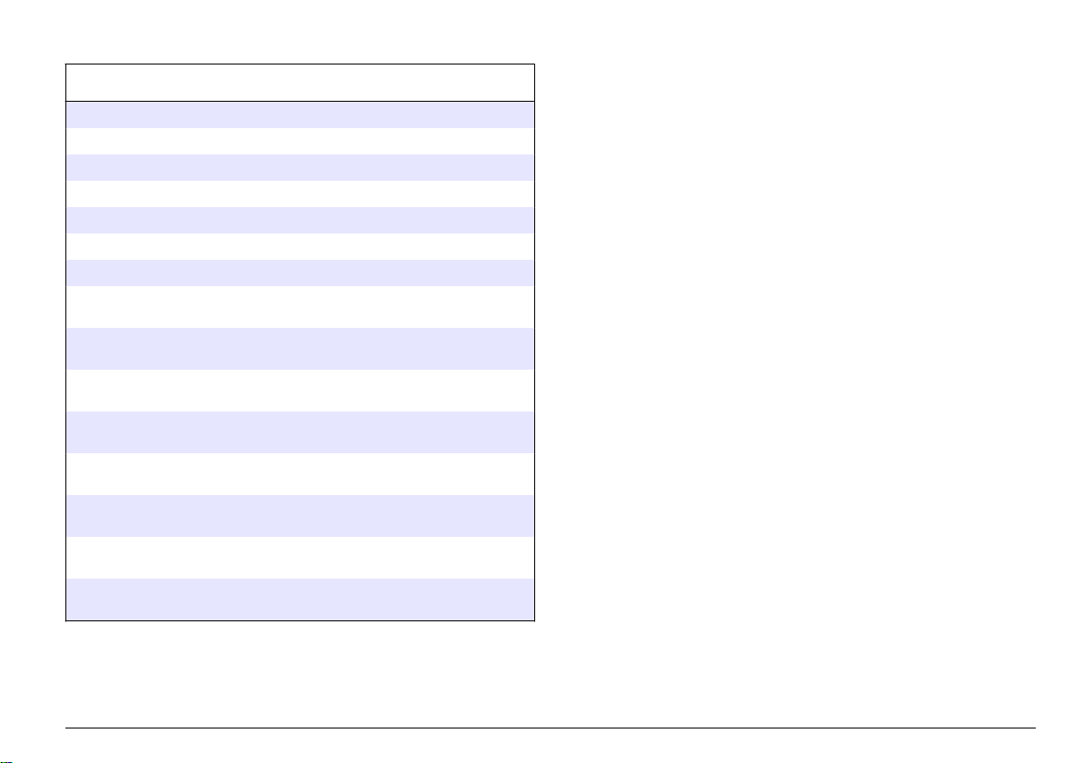
零件和附件
说明 型号
电缆,5 m (16 ft)
电缆,10 m (33 ft)
电缆,20 m (66 ft)
流通室,6 mm (¼ in.)NPT 螺纹
流通室,19 mm (¾ in.) NPT 螺纹
垫片,EDPM,38 mm (1.5 in.)
垫片,EDPM,51 mm (2 in.)
安装套件,具有 EPDM 垫片、管夹和不锈钢套圈(高 =
13 mm),38 mm (1.5 in.)内径,50.5 mm (1.99 in.) 外径
安装套件,具有 EPDM 垫片、管夹和不锈钢套圈(高 =
13 mm),51 mm (2 in.) 内径,64 mm (2.52 in.)外径
安装套件,具有 EPDM 垫片、管夹和不锈钢流通室,
38 mm (1.5 in.)内径,50.5 mm (1.99 in.) 外径
安装套件,具有 EPDM 垫片、管夹和不锈钢流通室,
51 mm (2 in.)内径,64 mm (2.52 in.)外径
证书,标准测试证书表明电极常数的实际值与 ISO 7888,
ASTM D5391 的值相差 2% 左右;50.5 mm (1.99 in.)外径
证书,可选合格证明(FDA 材料、不锈钢 EN
10204 3.1 B,粗糙系数 < 0.4 µm);mm (1.99 in.)外径
证书,标准测试证书表明电极常数的实际值与 ISO 7888,
ASTM D5391 的值相差 2% 左右;64 mm (2.52 in.)外径
证书,可选合格证明(FDA 材料、不锈钢 EN
10204 3.1 B,粗糙系数 < 0.4 µm);64 mm (2.52 in.)外径
08319=A=0005
08319=A=0010
08319=A=0020
08318=A=0001
08313=A=0001
429=500=380
429=500=510
08394=A=0380
08394=A=0510
08394=A=8150
08394=A=8200
08394=A=1500
08394=A=1511
08394=A=2000
08394=A=2011
中文
91
Page 92

目次
仕様 92 ページ メンテナンス 104 ページ
総合情報 92 ページ トラブルシューティング 104 ページ
設置 94 ページ 交換パーツおよびアクセサリー
操作 99 ページ
107 ページ
仕様
この仕様は予告なく変更されることがあります。
表 1 アナログモジュール仕様
仕様 詳細
測定範囲 セル定数 0.01: 0.01 ~ 200 µS/cm
セル定数 0.1: 0.1 µS ~ 2 mS/cm
セル定数 1: 1 µS ~ 20 mS/cm
応答時間 0.5 秒
再現性/精度(0~20 µS/cm)
精度(20~200,000 µS/cm) 読み取りの±0.5%
最大ケーブル長
仕様 詳細
温度素子
センサケーブル 4 芯 (シールドワイヤ 2 本)、5 m、10 m、または 20 m、定
PT100
格温度 150℃
±0.1/0.1 µS/cm
91 m
表 2 センサの仕様
表 2 センサの仕様 (続き)
仕様 詳細
接液面の材質 -
8310
接液面の材質 8311
接液面の材質 8312
接液面の材質 8315
接液面の材質 8316
接液面の材質 8317
接液面の材質 8394
温度/圧力限度 8315、8316、8317、
1
8394
温度/圧力限度 8310、8311、8312
黒色 PSU ボディ、ステンレス鋼 316L 内部電極、ステンレ
ス鋼 316L 外部電極、PSU 絶縁体、ガラス・ポリエステ
ル/IP65 コネクタ
黒色 PSU ボディ、ステンレス鋼 316L 内部電極、ステンレ
ス鋼 316L 外部電極、PSU 絶縁体、ガラス・ポリエステ
ル/IP65 コネクタ
黒色 PSU ボディ、グラファイト内部電極、グラファイト
外部電極、PSU 絶縁体、ガラス・ポリエステル/IP65 コネ
クタ
ステンレス鋼 316L ボディ、ステンレス鋼 316L 内部電極、
ステンレス鋼 316L 外部電極、PES 絶縁体、Viton® O リン
グ、ガラス・ポリエステル/IP65 コネクタ
ステンレス鋼 316L ボディ、ステンレス鋼 316L 内部電極、
ステンレス鋼 316L 外部電極、PES 絶縁体、Viton O リン
グ、ガラス・ポリエステル/IP65 コネクタ
ステンレス鋼 316L ボディ、グラファイト内部電極、グラ
ファイト外部電極、PES 絶縁体、Viton O リング、ガラス・
ポリエステル/IP65 コネクタ
ステンレス鋼ボディ、316L 電極、PEEK®、EPDM ガスケ
ット、ガラス・ポリエステル/IP65 コネクタ
150℃ (25 バール時)
125℃ (10 バール時)
総合情報
いかなる場合も、製造元は、例えそのような損害が生じる可能性につい
て報告を受けていたとしても、本マニュアルに含まれるいかなる瑕疵ま
1
取り付けハードウェアおよびサニタリークランプのその他のブランドは、記載の等級を下げる場合があります。
92
日本語
Page 93

たは脱落から生じる直接的、間接的、特定、付随的または結果的に生じ
る損害に関して責を負いません。製造元は、通知または義務なしに、随
時本マニュアルおよび製品において、その記載を変更する権利を留保し
ます。改訂版は、製造元の Web サイト上にあります。
安全情報
告 知
メーカーは、本製品の目的外使用または誤用に起因する直接損害、偶発的損害、
結果的損害を含むあらゆる損害に対して、適用法で認められている範囲で一切責
任を負わないものとします。ユーザーは、適用に伴う危険性を特定したり、装置
が誤作動した場合にプロセスを保護するための適切な機構を設けることに関し
て、全責任を負うものとします。
この機器の開梱、設定または操作を行う前に、このマニュアルをすべて
よく読んでください。危険および注意の注意事項に注意を払ってくださ
い。これを怠ると、使用者が重傷を負う可能性、あるいは機器が損傷を
受ける可能性があります。
本装置に備わっている保護機能が故障していないことを確認します。本
マニュアルで指定されている以外の方法で本装置を使用または設置しな
いでください。
危険情報の使用
危 険
回避しないと死亡または重傷につながる潜在的または切迫した危険な状況を示し
ます。
回避しなければ、死亡または重傷につながるおそれのある潜在的または切迫した
危険な状況を示します。
警 告
使用上の注意ラベル
測定器上に貼付されたラベルや注意書きを全てお読みください。これを
怠ると、人身傷害や装置の損傷につながるおそれがあります。測定器に
記載されたシンボルは、使用上の注意と共にマニュアルを参照してくだ
さい。
これは安全警報シンボルです。潜在的な障害を避けるためにこのシ
ンボルのすべて安全メッセージに従ってください。 装置上では、作業
または安全情報に関しては取り扱い説明書を参照してください。
このシンボルは、静電気放電 (ESD) に敏感なデバイスがあることと、
機器の破損を防止する措置をとる必要があることを示しています。
このシンボルが付いている電気機器は、 ヨーロッパ域内または公共の
廃棄処理システムで処分できません。古くなったり耐用年数を経た
機器は、廃棄するためにメーカーに無償返却してください。
製品の概要
このセンサはデータ収集と操作のために変換器と接続するように設計さ
れています。複数の変換器をこのセンサと共に使用できます。
様々な形状のセンサーをご利用いただけます。図 1 を参照してくださ
い。
注 意
軽傷または中程度のけがをする事故の原因となる可能性のある危険な状況を示し
ます。
回避しなければ、本製品を損傷する可能性のある状況や、特に強調したい情報を
示します。特に注意を要する情報。
告 知
日本語
93
Page 94
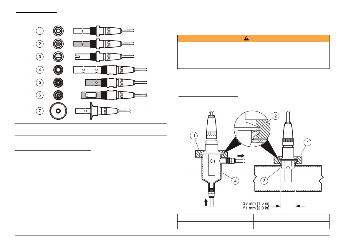
図 1 センサの外観
設置
取り付け
警 告
人体損傷の危険。センサを圧力容器から外すことは危険を招く恐れがあります。
これらのセンサの取り付けおよび取り外しは、高圧および高温時の正しい設置方
法について訓練を受けた技術者が行う必要があります。高圧および高温の液体輸
送システムを取り扱う際は、必ず業界で認定されている設備および安全手順を使
用してください。
異なるアプリケーションでセンサを使う場合の例は、図 2 または図 3 を
参照してください。センサは校正してから使用してください。センサの
校正 100 ページを参照してください。
図 2 サニタリー取り付け例
1 8310: k = 0.01、用途: 飲用水、廃水、
化学処理液、純水、軟水
2 8311: k = 0.1、用途: 8310 と同じ 6 8317: k = 1、用途: 8315 と同じ
3 8312: k = 1、用途: 8310 と同じ 7 8394: k = 0.01、サニタリー・タイ
4 8315: k = 0.01、用途: 純水製造監視
(イオン交換装置および蒸留器)、プ
ロセス水監視 (凝縮水、洗浄サイク
ル、熱交換器)
94
日本語
5 8316: k = 0.1、用途: 8315 と同じ
プ: Φ38 mm または Φ51 mm 用途:
製薬および食品産業での超純水監
視、CIP-SIP プロセスに最適
1 サニタリー・クランプ 3 フェルール (パイプに溶接)
2 ガスケット 4 フロースルー・チャンバー
Page 95

図 3 取り付け例
1 フロースルー T 字取り付け、PVC、19 mmNPT 2 フロースルー T 字取り付け、ステンレス鋼、6 mmNPT
日本語
95
Page 96
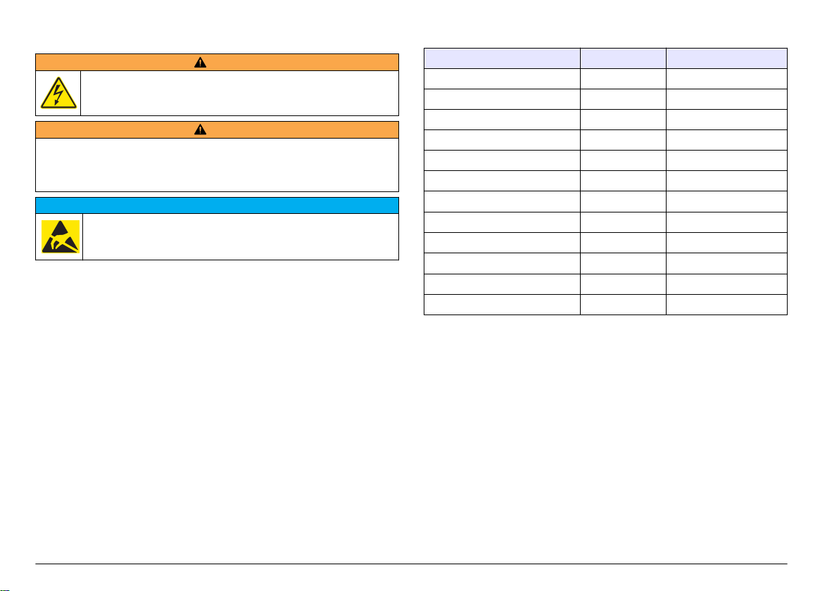
センサをアナログモジュールに接続
警 告
感電の危険の可能性。電気の接続を行う際には、常に装置の電源は切
ってください。
警 告
感電の危険性。変換器の高電圧配線は、変換器筐体の高電圧防護壁の後ろに施さ
れます。この防護壁は、資格のある取付け技術者が電源、リレー、またはアナロ
グおよびネットワーク カードの配線を取り付ける場合以外は、取り外さないで下
さい。
装置の損傷の可能性。静電気による装置内部の精密な電子部品の破損
により、装置の性能低下や故障を招く恐れがあります。
アナログモジュールを取り付けてセンサを接続するには、後続ページの
図に示したステップと表 3 を参照してください。必ず、先端が赤の白色
被覆のセンサ・ワイヤを変換器筐体に接続してください。
注: センサケーブルが短いために変換器に届かない場合は、延長ケーブルと終端ボ
ックスを使って延長する必要があります。
告 知
表 3 ポリメトロン伝導率センサの配線
コネクタピン番号 信号 センサの配線
1
2 — —
3
4 — —
5 — —
6 — —
7
8 — —
9 — —
10
11
12 — —
出力 白
グランド 黒
温度 - 黒
温度 + 青
入力 赤
96
日本語
Page 97

1 2
3 4
日本語
97
Page 98

5 6
7 8
98
日本語
Page 99

操作
ユーザーナビゲーション
キーパッドの説明とナビゲーション情報は変換器の説明書を参照してく
ださい。
センサの設定
設定メニューを使って、センサの識別情報を入力し、また、データ処理
と保存に関するオプションを変更します。
1. MENU キーを押して、センサの設定、[センサの選択]、設定を選択し
ます。
2. 矢印キーを使ってオプションを選択して、ENTER を押します。数字、
文字または句読点を入力するには、UP または DOWN 矢印キーを押
したままにします。右矢印キーを押して次のスペースに進みます。
オプション 説明
EDIT NAME(名前の編集) 測定画面の上部に表示されるセンサの名前を変
SENSOR S/N(センサ
S/N)
SELECT MEASURE(測
定の選択)
DISPLAYFORMAT(表示
形式)
MEAS UNITS(測定単位) 選択した測定の単位を変更します。電気伝導率:
TEMP UNITS(温度単位) 温度単位を℃(デフォルト)または°F に設定しま
更します。名前は、文字、数字、スペース、句読
点を含み、10 文字に制限されています。
センサのシリアル番号を入力できますが、長さ
は、文字、数字、スペース、句読点を含み、16 文
字に制限されています。
測定パラメータを電気伝導率 (デフォルト)、TDS
(総溶解固形物)、塩分濃度、または抵抗率に変更
します。パラメータが変更されると、他のすべて
の設定はデフォルト値にリセットされます。
測定画面に表示される小数位の数を自動(デフォ
ルト)、X.XX、XX.XX、XXX.X または XXXX に変
更します。自動に設定すると、少数位の数は測定
値の変化に応じて自動的に変わります。
µS/cm (デフォルト)、mS/cm、µS/m、mS/m また
は S/m。
す.
オプション 説明
温度補償 測定値に温度補正を追加します ‐ 線形 (デフォ
CELL CONSTANT(セル
定数)
CABLE LENGTH(ケーブ
ル長)
TEMP ELEMENT(温度素子)温度素子を PT100 または PT1000(デフォルト)に
ルト: 2.0 %/℃、25℃)、アンモニア、温度テーブ
ル (x、y 点を昇順に入力)、なし、自然水または純
水。特別なアプリケーションの場合は、ユーザー
定義線形補償を入力できます (0 ~ 4%/℃、0 ~
200℃)。自然水補償は TDS には使用できませ
ん。
セル定数の範囲を [0.05]、[0.5]、[1.0] (デフォル
ト)、[5.0]、[10.0]、[0.01 Polymetron (0.01 ポリメ
トロン)]、[0.1 Polymetron (0.1 ポリメトロン)]、
または [1.0 Polymetron (1.0 ポリメトロン)] に設
定します。範囲選択後、センサ・ケーブルのラベ
ルに記載されている保証 K 値を入力します。保
証 K 値を入力すると、校正曲線が定義されます。
センサケーブルの実際の長さを入力すると、測定
精度が向上します(ポリメトロンセンサのデフォ
ルト:5 フィート)。
対して自動温度補償に設定します。選択後、ユー
ザーは、最高の精度を得られるように、センサケ
ーブル上のラベルに記載されている T 係数(認証
済み)を入力できます。温度素子が使用されない
場合は、タイプをマニュアルに設定でき、温度補
償値を入力できます(マニュアルデフォルト:
25 ℃)。
注: PT100またはPT1000のセンサ エレ
メントがマニュアルに設定されて、センサが交換
されるか、またはセンサ日数がリセットされる場
合、
TEMP ELEMENT(
温度素子)が自動的にデフ
ォルト設定に変わります。
FILTER(フィルタ) 信号の安定性を向上させる時定数を設定します。
時定数により指定時間中の平均値が計算されま
す‐0(無効、デフォルト)から 60 秒(60 秒間の信
号値の平均)。フィルタによってセンサ信号がプ
ロセス中の実際の変化よりも遅くなります。
日本語
99
Page 100

オプション 説明
LOG SETUP(ログの設定)データログへのデータ保存の時間間隔を設定し
RESET DEFAULTS(デフ
ォルトにリセット)
ます-5、30 秒、1、2、5、10、15(デフォルト)、
30、60 分。
設定メニューをデフォルト設定に戻します。す
べてのユーザー定義設定が失われます。
非標準ケーブル長に対して T-係数を調整
センサケーブルを標準の 6 m(20 フィート)から延長または縮小すると、
ケーブルの抵抗が変化します。この変化により、温度測定の精度が低下
します。この差異を補正するために、新しい T-係数を計算します。
注: この手順は
温度エレメント付きのセンサは精度が劣ります。
PT1000
温度エレメント付きのセンサにのみ適用されます。
PT100
1. センサおよび温度計のような信頼性の高い測定器で溶液の温度を測
定します。
2. センサで測定した温度と測定器で測定した温度(実測)との差異を記録
します。
例えば、実測温度が
50
℃でセンサの読み取り値が
53
℃の場合、その
差異は 3℃になります。
3. この差異に 3.85 を掛けて調整値を得ます。
例
: 3 x 3.85 = 11.55
4. 新しい T-係数の計算:
• センサ温度 > 実測‐調整値をセンサケーブルの T-係数に加算
• センサ温度 < 実測‐調整値をセンサケーブルの T-係数から減算
5. 設定、温度エレメントメニューで新しい T-係数を入力します。
センサの校正
センサの校正について
校正中はデータはデータログに送信されません。このように、データロ
グはデータが途絶える領域があります。
ゼロ校正の手順
ゼロ校正の手順に従って伝導率センサのゼロ点を校正します。ゼロ点
は、標準液またはプロセス試料で初めてセンサを校正する前に校正して
おかなければなりません。
1. センサを設備から外します。きれいなタオルでセンサをふくか、エア
コンプレッサーを使用してセンサをきれいで乾いた状態にします。
2. [MENU(メニュー)]キーを押して、[Sensor Setup(センサの設定)]、
[Select Sensor(センサの選択)]、[Calibrate(校正)]と選択します。
3. ENTER を押して、ゼロ校正を選択します。
4. 変換器のセキュリティメニューでパスコードが有効になっている場
合は、パスコードを入力します。
5. 校正時の出力信号のオプションを選択します。
オプション 説明
アクティブ 校正手順中は、装置は最新の測定出力値を送信します。
ホールド 校正手順中は、センサの出力値は最新の測定値に保持されます。
転送 校正中は、設定されている出力値が送信されます。設定値を変
更するには、変換器のユーザーマニュアルを参照してください。
6. 乾燥したセンサを空中に保持して、ENTER を押します。
7. 校正結果の確認:
• 合格-ゼロ点が設定されています。
• 失敗‐値が許容限度外です。センサが乾いていることを確認して、
ゼロ校正の手順を繰り返してください。原因が延長ケーブルへの
電子ノイズではないことを確認して下さい。
8. 校正に合格した場合は、[ENTER (入力)] を押して続行します。
9. sc100 変換器の場合は、手順 12 に進みます。
10. [Calibration Options (校正オプション)] メニューのオペレータ ID の
オプションが [Yes (はい)] に設定されている場合は、オペレータ ID
を入力します。校正オプションの変更 103 ページを参照してくださ
い。
100
日本語
 Loading...