

Page 1
DOC023.53.90627
PHOSPHAX sc LR, PHOSPHAX indoor sc LR
User Manual
08/2018, Edition 1
Page 2

Page 3

Table of Contents
Section 1 Specifications.................................................................................................................... 3
1.1 Sample requirements................................................................................................................... 4
1.2 Interferences................................................................................................................................ 4
Section 2 General information......................................................................................................... 5
2.1 Safety information........................................................................................................................ 5
2.1.1 Use of hazard information................................................................................................... 5
2.1.2 Precautionary labels............................................................................................................ 5
2.1.3 Chemical and biological safety............................................................................................ 6
2.1.4 Certification......................................................................................................................... 6
2.2 Product overview..........................................................................................................................7
2.2.1 Status indicator light............................................................................................................ 9
2.3 Product components.................................................................................................................... 9
Section 3 Installation........................................................................................................................ 11
3.1 Installation guidelines................................................................................................................. 11
3.2 Mechanical installation............................................................................................................... 11
3.2.1 Attach the instrument to a wall.......................................................................................... 11
3.2.2 Open the enclosure........................................................................................................... 13
3.2.3 Remove the transport lock................................................................................................ 14
3.3 Electrical connectors and plumbing access ports..................................................................... 15
3.4 Plumbing.................................................................................................................................... 15
3.4.1 Sample line guidelines...................................................................................................... 15
3.4.2 Drain line guidelines.......................................................................................................... 16
3.4.3 Tubing considerations....................................................................................................... 16
3.5 System configuration options..................................................................................................... 16
3.5.1 Plumbing one outdoor analyzer.........................................................................................18
3.5.2 Plumbing two outdoor analyzers....................................................................................... 19
3.5.3 Plumbing one outdoor analyzer with continuous sample feed.......................................... 21
3.5.4 Plumbing two outdoor analyzers with continuous sample feed......................................... 22
3.5.5 Plumbing one indoor analyzer........................................................................................... 24
3.5.6 Plumbing two indoor analyzers......................................................................................... 25
3.5.7 Plumbing one indoor analyzer with continuous sample feed............................................ 27
3.5.8 Plumbing two indoor analyzers with continuous sample feed........................................... 27
3.5.9 Two-parameter configuration............................................................................................ 29
3.6 Install the collecting tray and humidity sensor............................................................................32
3.7 Install the reagents..................................................................................................................... 32
3.8 Electrical installation...................................................................................................................34
3.8.1 Electrostatic discharge (ESD) considerations................................................................... 34
3.8.2 Connect the optional heated drain.................................................................................... 34
3.8.3 Supply power to the analyzer............................................................................................ 35
3.9 Close the analyzer..................................................................................................................... 37
Section 4 Operation.......................................................................................................................... 39
4.1 User navigation.......................................................................................................................... 39
4.2 Startup........................................................................................................................................39
4.3 Configure the instrument............................................................................................................ 39
4.4 Configure the calibration settings............................................................................................... 40
4.5 Show analyzer data....................................................................................................................40
4.6 Configure the maintenance settings...........................................................................................41
4.7 System configuration..................................................................................................................42
4.8 Do a measurement.....................................................................................................................42
4.9 Do a calibration.......................................................................................................................... 42
4.10 Do a clean cycle....................................................................................................................... 42
1
Page 4

Table of Contents
Section 5 Maintenance..................................................................................................................... 45
5.1 Maintenance schedule............................................................................................................... 45
5.2 Examine for damage.................................................................................................................. 45
5.3 Examine the tubing and fittings.................................................................................................. 45
5.4 Clean the instrument.................................................................................................................. 46
5.5 Clean spills................................................................................................................................. 46
5.6 Replace the reagents................................................................................................................. 46
5.7 Replace the air filter pads.......................................................................................................... 46
5.8 Replace the pump head for air pump (piston pump).................................................................. 48
5.9 Do a leakage test....................................................................................................................... 49
5.10 Replace the fuses.................................................................................................................... 50
5.11 Do a validation check (analytical quality assurance)................................................................50
5.11.1 Validation with standard solution..................................................................................... 50
5.11.2 Validation with applicable laboratory measurement (cuvette test).................................. 51
5.12 Put the analyzer in shutdown mode......................................................................................... 53
5.12.1 Prepare the analyzer for storage..................................................................................... 53
Section 6 Troubleshooting..............................................................................................................55
6.1 Troubleshoot the controller........................................................................................................ 55
6.2 Troubleshooting the analyzer..................................................................................................... 55
Section 7 Replacement parts and accessories.......................................................................... 59
2
Page 5

Section 1 Specifications
Specifications are subject to change without notice.
Specification Details
Dimensions (W x H x D) PHOSPHAX sc LR: 540 × 720 × 390 mm (21.25 × 28.35 ×
15.35 in.)
PHOSPHAX indoor sc LR: 540 × 720 × 370 mm (21.25 ×
28.35 × 14.5 in.)
Enclosure Enclosure rating: PHOSPHAX sc LR, IP55; PHOSPHAX
indoor sc LR, IP54
Enclosure material: ASA/PC UV-resistant
Weight PHOSPHAX sc LR: Approximately 31 kg without chemicals
PHOSPHAX indoor sc LR: Approximately 29 kg without
chemicals
Measuring method Two-beam photometer (yellow method)
Measuring range 0.015 to 2 mg/L PO4–P
Detection limit 0.015 mg/L with standard
Measuring accuracy (with standard solution) 2% of the measured value + 0.015 mg/L
Repeatability (with standard solution) 0.7% of the measured value + 0.005 mg/L
1
Response time (90 %) 10 minutes
Adjustable measuring interval 10 to 120 minutes
Power supply With power cable, connected to a SC1000 controller or
SC200 with power box.
Analyzer and drain tubing: 115 V or 230 V versions
Data transmission SC standard
Electrical power consumption 500 VA
Electrical fuse protection Supplied by SC1000 controller or SC200 controller with
power box.
Maximum of two analyzers for each SC Controller.
Outputs Relay, analog outputs, network interface through
SC1000/SC200 controller2.
Operating temperature PHOSPHAX sc LR: –20 to 40 °C (–4 to 104 °F); 95% relative
humidity, non-condensing, non-corrosive
PHOSPHAX indoor sc LR: 5 to 40 °C (41 to 104 °F); 95%
relative humidity, non-condensing, non-corrosive
Storage temperature –20 to 60 °C (–4 to 140 °F); 95% relative humidity, non-
condensing
Data and power cable lengths 2 m (80 in.) from edge of enclosure
Certifications CE marked. Listed to UL and CSA safety standards by TÜV.
Warranty 1 year (EU: 2 years)
1
At room temperature. ± 4% for values > 1 mg/L PO4–P along the full temperature range.
2
Refer to the controller documentation for more information about the relay, analog and digital outputs.
3
Page 6
Specifications
1.1 Sample requirements
The water from the sample source(s) must agree with the specifications that follow.
Specification Description
Sample flow rate 1.0 to 20.0 L/h
Sample pressure With continuous sample preparation: –30 mbar to +50 mbar at overflow vessel.
Sample temperature 4 to 45 °C (39 to 113 °F)
Sample quality Ultra filtrated or comparable
Sample pH 5 to 9
1.2 Interferences
Table 1 shows that the ions were individually examined to the given concentrations and
do not cause interference. No cumulative effects or influences of other ions were found.
Verify the measurement results with sample dilutions or standard additions.
Table 1 Interfering substances
Interfering substance Interference level
–
Cl
5000 mg/L
4
Page 7
Section 2 General information
In no event will the manufacturer be liable for direct, indirect, special, incidental or
consequential damages resulting from any defect or omission in this manual. The
manufacturer reserves the right to make changes in this manual and the products it
describes at any time, without notice or obligation. Revised editions are found on the
manufacturer’s website.
2.1 Safety information
The manufacturer is not responsible for any damages due to misapplication or misuse of this
product including, without limitation, direct, incidental and consequential damages, and disclaims
such damages to the full extent permitted under applicable law. The user is solely responsible to
identify critical application risks and install appropriate mechanisms to protect processes during a
possible equipment malfunction.
Please read this entire manual before unpacking, setting up or operating this equipment.
Pay attention to all danger and caution statements. Failure to do so could result in serious
injury to the operator or damage to the equipment.
Make sure that the protection provided by this equipment is not impaired. Do not use or
install this equipment in any manner other than that specified in this manual.
2.1.1 Use of hazard information
Indicates a potentially or imminently hazardous situation which, if not avoided, will result in death
or serious injury.
Indicates a potentially or imminently hazardous situation which, if not avoided, could result in
death or serious injury.
Indicates a potentially hazardous situation that may result in minor or moderate injury.
N O T I C E
D A N G E R
W A R N I N G
C A U T I O N
Indicates a situation which, if not avoided, may cause damage to the instrument. Information that
requires special emphasis.
2.1.2 Precautionary labels
Read all labels and tags attached to the instrument. Personal injury or damage to the
instrument could occur if not observed. A symbol on the instrument is referenced in the
manual with a precautionary statement.
This symbol, if noted on the instrument, references the instruction manual for operation and/or safety information.
Electrical equipment marked with this symbol may not be disposed of in European domestic or public disposal
systems. Return old or end-of-life equipment to the manufacturer for disposal at no charge to the user.
This symbol indicates that a risk of electrical shock and/or electrocution exists.
N O T I C E
5
Page 8
General information
This symbol indicates the need for protective eye wear.
This symbol indicates that the marked item requires a protective earth connection. If the instrument is not supplied
with a ground plug on a cord, make the protective earth connection to the protective conductor terminal.
This symbol, when noted on the product, identifies the location of a fuse or current limiting device.
This symbol identifies a risk of chemical harm and indicates that only individuals qualified and trained to work with
chemicals should handle chemicals or perform maintenance on chemical delivery systems associated with the
equipment.
This symbol indicates that the marked item can be hot and should not be touched without care.
This symbol indicates the presence of devices sensitive to Electro-static Discharge (ESD) and indicates that care
must be taken to prevent damage with the equipment.
This symbol indicates that the object is heavy.
This symbol indicates that the marked item should not be touched.
2.1.3 Chemical and biological safety
Chemical or biological hazards. If this instrument is used to monitor a treatment process
and/or chemical feed system for which there are regulatory limits and monitoring
requirements related to public health, public safety, food or beverage manufacture or
processing, it is the responsibility of the user of this instrument to know and abide by any
applicable regulation and to have sufficient and appropriate mechanisms in place for
compliance with applicable regulations in the event of malfunction of the instrument.
2.1.4 Certification
This equipment is not intended for use in residential environments and may not provide adequate
protection to radio reception in such environments.
Canadian Radio Interference-Causing Equipment Regulation, IECS-003, Class A:
Supporting test records reside with the manufacturer.
This Class A digital apparatus meets all requirements of the Canadian Interference-
Causing Equipment Regulations.
Cet appareil numérique de classe A répond à toutes les exigences de la réglementation
canadienne sur les équipements provoquant des interférences.
FCC Part 15, Class "A" Limits
Supporting test records reside with the manufacturer. The device complies with Part 15 of
the FCC Rules. Operation is subject to the following conditions:
D A N G E R
C A U T I O N
1. The equipment may not cause harmful interference.
2. The equipment must accept any interference received, including interference that
may cause undesired operation.
6
Page 9

Changes or modifications to this equipment not expressly approved by the party
responsible for compliance could void the user's authority to operate the equipment. This
equipment has been tested and found to comply with the limits for a Class A digital
device, pursuant to Part 15 of the FCC rules. These limits are designed to provide
reasonable protection against harmful interference when the equipment is operated in a
commercial environment. This equipment generates, uses and can radiate radio
frequency energy and, if not installed and used in accordance with the instruction manual,
may cause harmful interference to radio communications. Operation of this equipment in
a residential area is likely to cause harmful interference, in which case the user will be
required to correct the interference at their expense. The following techniques can be
used to reduce interference problems:
1. Disconnect the equipment from its power source to verify that it is or is not the source
of the interference.
2. If the equipment is connected to the same outlet as the device experiencing
interference, connect the equipment to a different outlet.
3. Move the equipment away from the device receiving the interference.
4. Reposition the receiving antenna for the device receiving the interference.
5. Try combinations of the above.
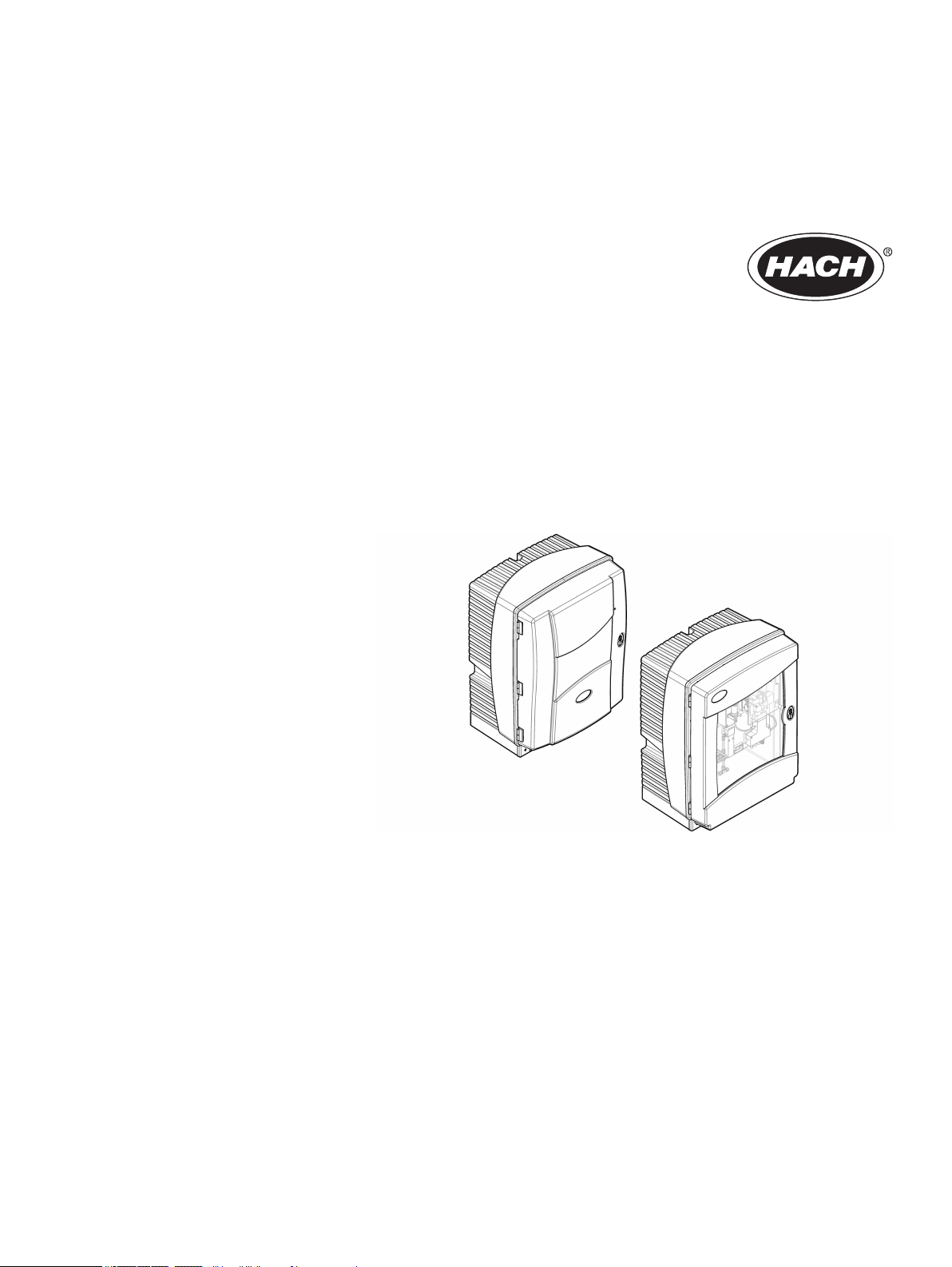
2.2 Product overview
General information
The PHOSPHAX sc LR is a one-channel analyzer that measures ortho-phosphate ions
3—
(PO
) in waste water and surface water. The analyzer does not measure diphosphates
4
or polyphosphates. The measuring principle is based on the Vanadat-Molybdat method,
also known as the Yellow method.
The analyzer is used with an SC Controller. The measured value shows on the controller
display as PO4–P (default) or PO
3—
.
4
There are two analyzer models available:
• PHOSPHAX sc LR: weather-resistant enclosure for outdoor installation
• PHOSPHAX indoor sc LR: for indoor installation
The reagents and standards necessary for the chemical analysis are internally installed in
the analyzer enclosure. The analyzer uses pumps, valves and syringes to move the
sample and reagents to the measuring cell on the analytics panel. When the
measurement cycle is complete, the analyzer discards the sample through the drain line.
The analyzer can automatically do cleaning cycles and calibrations for better
measurement performance. Refer to Figure 1.
The sample must be prepared and filtered before analysis. Refer to Sample requirements
on page 4. Based on the system configuration, one or two analyzers can connect to a
FILTRAX instrument for filtration (or an applicable sample feed) and measure one or two
parameters. Refer to System configuration options on page 16.
7
Page 10
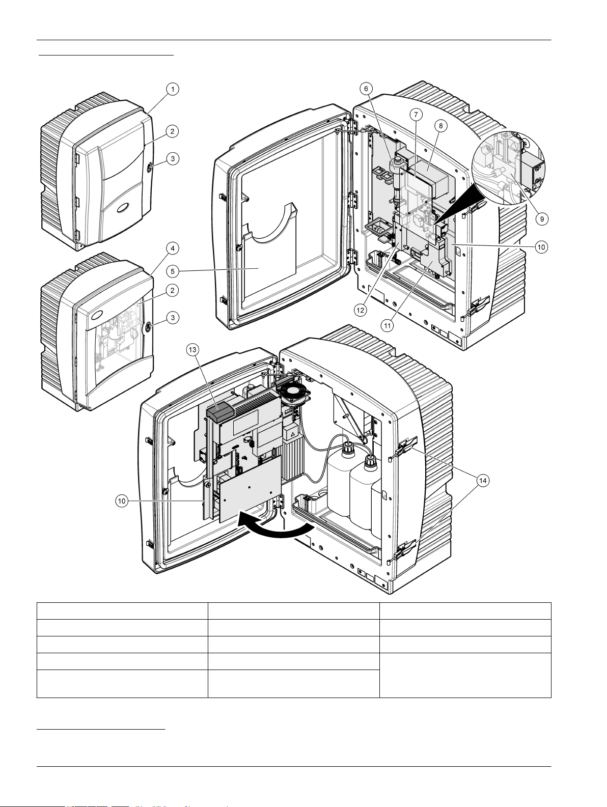
General information
Figure 1 Product overview
1 PHOSPHAX sc LR 6 Piston pump 11 Valve block
2 Status indicator light
3
7 Safety glass 12 Overflow vessel
3 Door lock 8 Reagent pumps 13 Transport lock
4 PHOSPHAX indoor sc LR 9 Measuring cell 14 Lever
5 Pocket for manual (only in outdoor
10 Analytics panel
models)
3
Refer to Status indicator light on page 9.
4
Refer to Remove the transport lock on page 14.
8
4
Page 11

General information
2.2.1 Status indicator light
The status indicator light shows the analyzer condition. Refer to Table 2.
Table 2 Status indicator description
Color Status
Green The analyzer is in operation with no warnings, errors or reminders.
Orange The analyzer is in operation with active warnings or reminders.
Red The analyzer is not in operation because of an error condition. An important problem has occurred. It is necessary
to resolve the error before further operation is possible.
Flashing There is no communications between the analyzer and the controller.
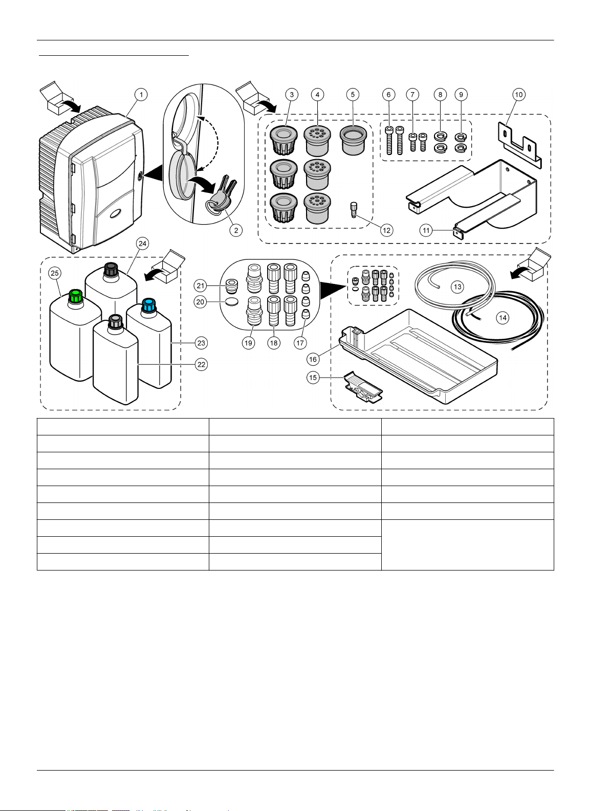
2.3 Product components
Make sure that all components have been received. Refer to Figure 2. If any items are
missing or damaged, contact the manufacturer or a sales representative immediately.
9
Page 12
General information
Figure 2 Product components
1 PHOSPHAX sc LR 10 Angle bracket, wall mount 19 Hose plug (2x)
2 Door keys 11 Console bracket, wall mount 20 Sealing disc
3 Tubing plug (3x) 12 Blind plug 21 Blind plug
4 Sealing plug (3x) 13 Sample tube 22 Cleaning Solution C
5 Sealing plug type 2 (not used) 14 Drain tube 23 Standard Solution S
6 Screw, M5 × 40 (2x) 15 Tube cutter 24 Reagent A
7 Screw, M5 × 8 (2x) 16 Collecting tray 25 Reagent B
8 Lock washer, M5 (2x) 17 Ferrule (4x)
9 Lock washer, M6 (2x) 18 Flangeless nut (4x)
10
Page 13
Section 3 Installation
Multiple hazards. Only qualified personnel must conduct the tasks described in this
section of the document.
3.1 Installation guidelines
Install the instrument:
• As near the sample source as possible to decrease analysis delay
• In a clean, dry, well ventilated and temperature controlled location
• In a location with minimum vibrations that has no direct exposure to sunlight
• In an environmental enclosure that supplies protection from precipitation and direct
sunlight, good ventilation and temperature control if installed outdoors
• In a location where the power switch and power cord are visible and easily accessible
• In a location where there is sufficient clearance around it to make plumbing and
electrical connections
3.2 Mechanical installation
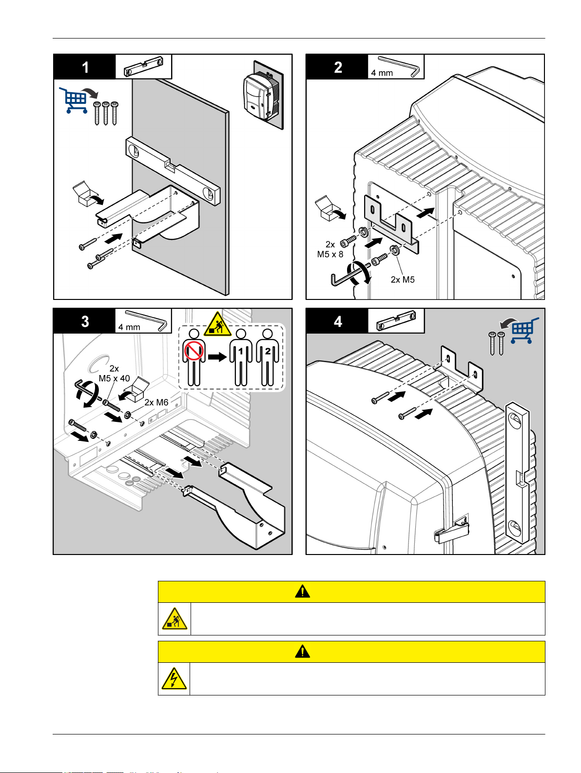
3.2.1 Attach the instrument to a wall
Risk of injury or death. Make sure that the wall mounting is able to hold 4 times the weight
of the equipment.
D A N G E R
D A N G E R
C A U T I O N
Personal injury hazard.
Instruments or components are heavy. Use assistance to install or move.
The object is heavy. Make sure that the instrument is securely attached to a wall, table or
floor for a safe operation.
Attach the instrument upright and level on a flat, vertical surface. Keep a minimum
clearance of 813 mm (32 in.) in front of the instrument to open the door. Refer to Figure 3.
Mounting hardware is supplied by the user. Make sure that the fastening has sufficient
load bearing capacity (approximately 160 kg). The wall plugs must be selected and
approved to suit the properties of the wall. Refer to the illustrated steps that follow.
For rail mount and stand mount installations, refer to the documentation supplied with the
mounting hardware.
11
Page 14
Installation
Figure 3 Mounting dimensions
12
Page 15
Installation
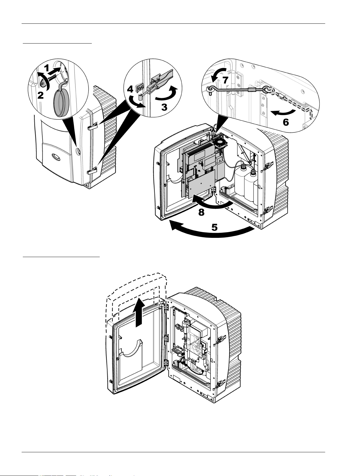
3.2.2 Open the enclosure
Open the analyzer enclosure to get access to the wiring connections and plumbing.
C A U T I O N
Personal injury hazard. The object is heavy. Make sure that the instrument is securely
attached to a wall, table or floor for a safe operation.
C A U T I O N
Electrical shock hazard. Make sure that no water can enter the enclosure or come into
contact with the circuit boards.
13
Page 16
Installation
Figure 4 Open the door
Use the door hook to open the door safely. Refer to the illustrated steps that follow.
As an alternative, remove the door for better access during installation and maintenance
procedures. Refer to Figure 5. Make sure to install and close the door before operation.
Figure 5 Remove the door
3.2.3 Remove the transport lock
Remove the transport lock from the analyzer. Refer to Figure 1 on page 8.
Note: Keep the transport lock for storage or shipping.
14
Page 17
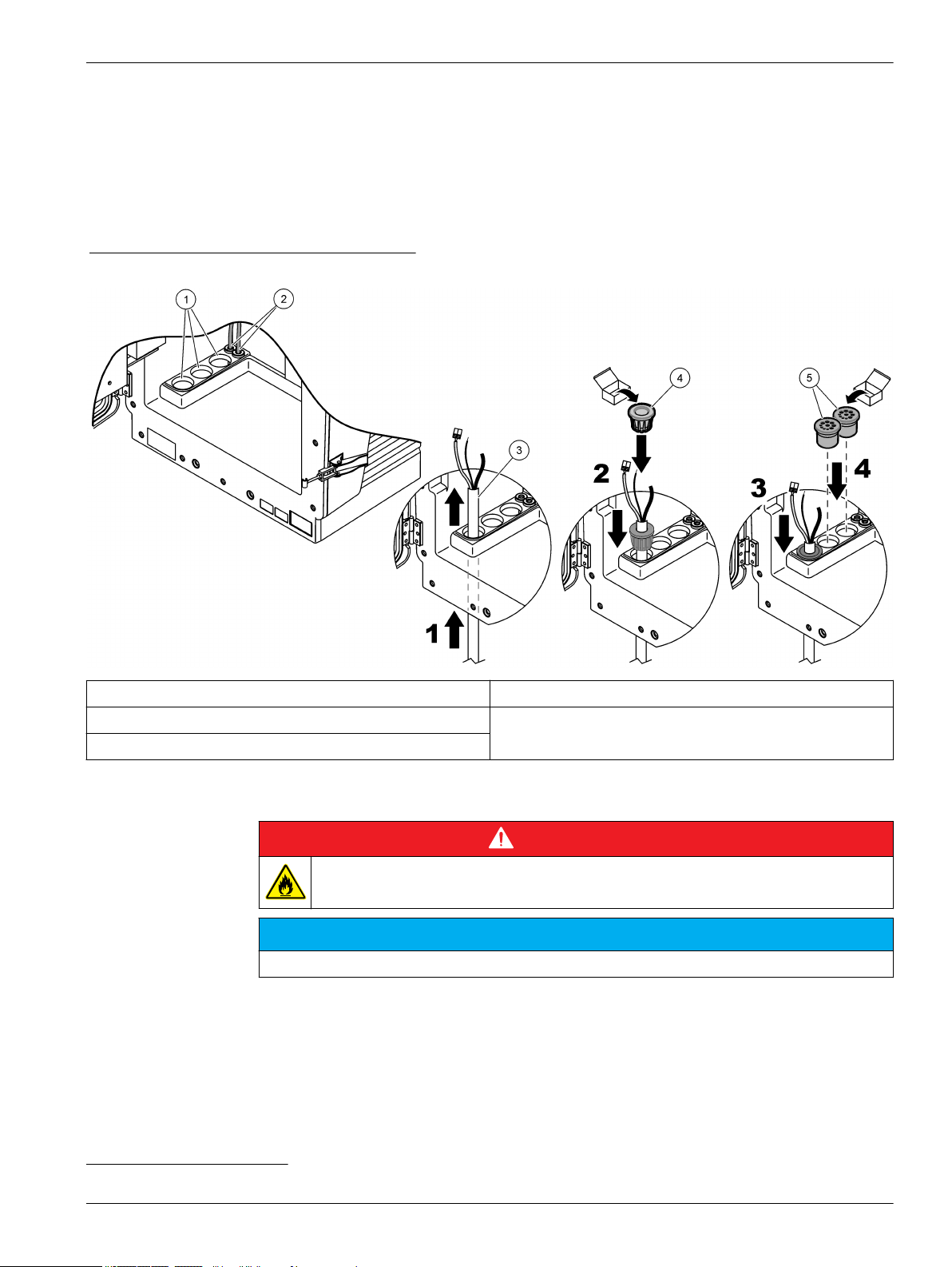
3.3 Electrical connectors and plumbing access ports
Figure 6 shows the electrical connectors and fittings on the instrument. Use the tubing
plug to put tubing or cables through the analyzer access ports. To keep the environmental
rating of the enclosure, make sure that there is a sealing plug in the access ports that are
not used.
Refer to System configuration options on page 16 to find the correct plumbing
installation.
Figure 6 Electrical connectors and fittings
Installation
1 Analyzer access ports 4 Tubing plug
2 Power and data connections (factory installed) 5 Sealing plug5.
3 Tubing or cables
3.4 Plumbing
D A N G E R
Fire hazard. This product is not designed for use with flammable liquids.
N O T I C E
Do not install reagents until all plumbing is complete.
Make sure to use the specified tubing size.
3.4.1 Sample line guidelines
Select a good, representative sampling point for the best instrument performance. The
sample must be representative of the entire system.
To prevent erratic readings:
• Collect samples from locations that are sufficiently distant from points of chemical
additions to the process stream.
5
Use the sealing plug to close access ports that are not used.
15
Page 18
Installation
• Make sure that the samples are sufficiently mixed.
• Make sure that all chemical reactions are complete.
3.4.2 Drain line guidelines
Correct installation of the drain lines is important to make sure that all of the liquid is
removed from the instrument. Incorrect installation can cause liquid to go back into the
instrument and cause damage.
• Make the drain lines as short as possible.
• Make sure that the drain lines have a constant slope down.
• Make sure that the drain lines do not have sharp bends and are not pinched.
• Make sure that the drain lines are open to air and are at zero pressure.
3.4.3 Tubing considerations
Plan cable and tubing path to prevent sharp bends and tripping hazards. The analyzer
uses different tubing types for plumbing connections. The type of tubing is based on the
analyzer configuration:
• Ø 3.2 mm: sample line tubing
• Ø 6 mm: unheated drain tubing
• Ø 22 mm: heated drain tubing
Always put the drain tubing so that there is a continuous fall (minimum 3°) and the outlet
is open to air (not pressurized). Make sure the drain tubing is less than 2 meters (6.56 ft).
3.5 System configuration options
Before plumbing or electrical installation, find the correct system configuration option
based on the number of analyzers, sample filtration, drain line and number of measured
parameters6. Refer to Table 3.
Table 3 System configuration options
Location Filtration Drain Number of
analyzers
Outdoor FILTRAX Heated 1 1 Refer to Plumbing one
2 heated 2 2 Refer to Plumbing two
Number of
parameters
Plumbing option
outdoor analyzer
on page 18.
outdoor analyzers
on page 19.
6
Refer to Two-parameter configuration on page 29.
16
Page 19
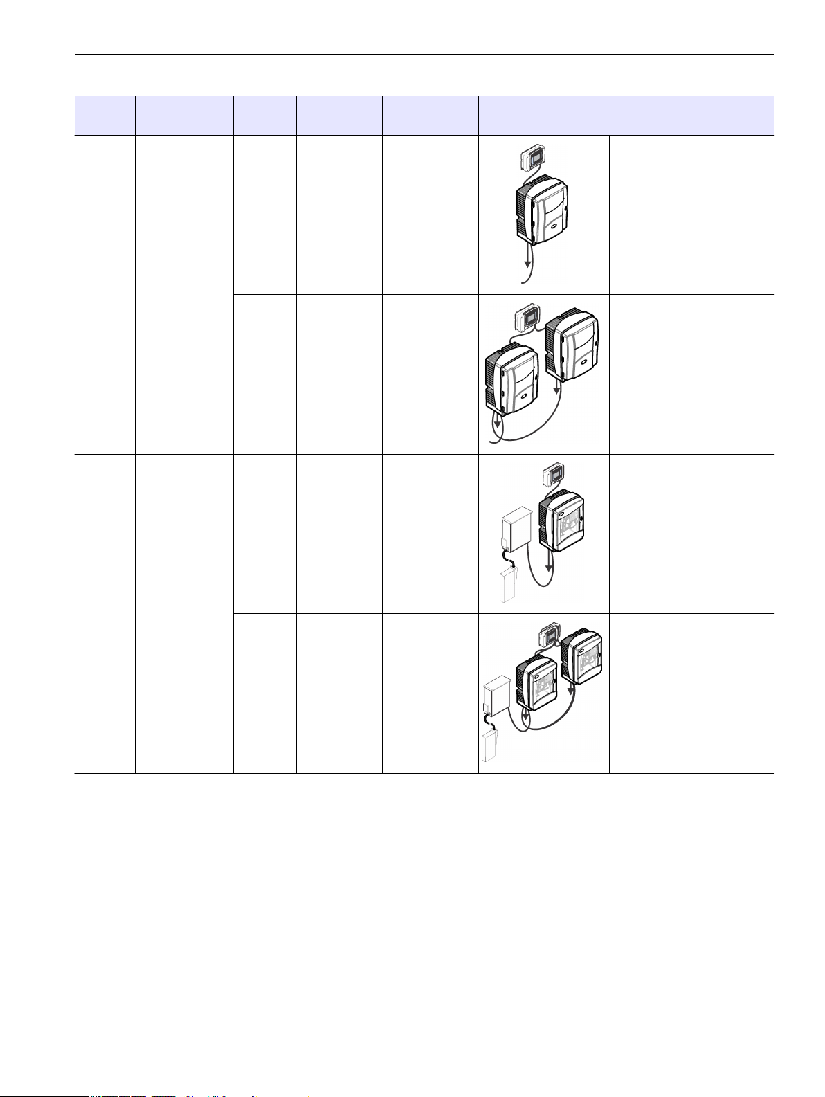
Table 3 System configuration options (continued)
Installation
Location Filtration Drain Number of
analyzers
Outdoor Continuous
sample feed
Indoor FILTRAX Unheated 1 1 Refer to Plumbing one
Heated 1 1 Refer to Plumbing one
2 heated 2 2 Refer to Plumbing two
Number of
parameters
Plumbing option
outdoor analyzer with
continuous sample feed
on page 21.
outdoor analyzers with
continuous sample feed
on page 22.
indoor analyzer
on page 24.
Unheated 2 2 Refer to Plumbing two
indoor analyzers
on page 25.
17
Page 20

Installation
Table 3 System configuration options (continued)
Location Filtration Drain Number of
analyzers
Indoor Continuous
sample feed
Unheated 1 1 Refer to Plumbing one
Unheated 2 2 Refer to Plumbing two
3.5.1 Plumbing one outdoor analyzer
This system configuration option uses one sc analyzer with the FILTRAX instrument for
the sample line. The waste from the analyzer is released into an open drain through the
optional heated drain hose.
Do the steps that follow to install one outdoor analyzer. Refer to Figure 7.
Number of
parameters
Plumbing option
indoor analyzer with
continuous sample feed
on page 27.
indoor analyzers with
continuous sample feed
on page 27.
1. Install the FILTRAX into the sample stream. Refer to the FILTRAX User Manual for
more information.
2. Use a tubing plug to put the heated sample hose from the FILTRAX through the
analyzer access port.
3. Use a tubing plug to put the heated drain hose through the analyzer access port.
Note: The two samples lines of the heated drain hose are not used.
4. Use the sealing plug to close access ports that are not used.
5. Connect the heated drain connections. Refer to Connect the optional heated drain
on page 34.
6. Connect the heated drain tube to the sample outlet T-fitting.
18
Page 21

Figure 7 Plumbing one outdoor analyzer
Installation
1 Heated drain sample lines (not used) 3 FILTRAX sample line
2 Heated drain
3.5.2 Plumbing two outdoor analyzers
This system configuration option uses two sc analyzers with the FILTRAX instrument for
the sample line. The sample from the FILTRAX goes to the first analyzer, which must
change to a 2-parameter configuration. The heated drain hose connects to the two
analyzers. The waste from the two analyzers is released into a drain through the second
heated drain hose.
Do the steps that follow to install two outdoor analyzers. Refer to Figure 8.
1. Install the FILTRAX into the sample stream. Refer to the FILTRAX User Manual for
more information.
Install the first sc analyzer as follows:
2. Use a tubing plug to put the heated sample hose from the FILTRAX through the
analyzer access port.
3. Use a tubing plug to put the heated drain hose through the analyzer access port.
4. Use the sealing plug to close access ports that are not used.
5. Connect the heated drain connections. Refer to Connect the optional heated drain
on page 34.
6. Remove the pre-installed drain tube attached to the valve block. Remove the T-fitting
from the drain tube. Keep the T-fitting for use with the second analyzer 2.
7. Connect the heated drain tube to the valve block connector.
8. Connect the sample line from the FILTRAX to the bottom inlet on the overflow vessel.
9. Connect one of the sample lines from the heated drain to the overflow vessel.
19
Page 22

Installation
10. Change the analyzer to a two-parameter configuration. Refer to Two-parameter
configuration on page 29.
Install the second sc analyzer as follows:
11. Use a tubing plug to put the heated drain hose from first analyzer through one access
port of second analyzer.
12. Use a tubing plug to put a second heated drain hose through one analyzer access
port.
13. Use the sealing plug to close access ports that are not used.
14. Connect the heated drain connections. Refer to Connect the optional heated drain
on page 34.
15. Cut 25 mm (0.98 in.) from the drain tube that was removed from first analyzer.
16. Connect the tube cut to the T-fitting on the second analyzer.
17. Connect the T-fitting removed from first analyzer to the other end of the tube cut.
18. Connect the heated drain tube from first analyzer and second analyzer to the T-fitting.
19. Connect the sample line from first analyzer to the bottom inlet on the overflow vessel.
20
Page 23

Figure 8 Plumbing two outdoor analyzers
Installation
1 PHOSPHAX sc LR analyzer 6 T-fitting from first analyzer
2 Heated drain sample lines (not used) 7 Heated drain
3 AMTAX sc analyzer 8 Heated drain from first analyzer
4 Sample line to second analyzer (overflow vessel tube) 9 FILTRAX sample line
5 Drain tube cut from first analyzer
3.5.3 Plumbing one outdoor analyzer with continuous sample feed
This configuration option uses one outdoor sc analyzer and one sample preparation unit
that supplies a continuous sample stream. The waste from the analyzer is released into
an open drain through the optional heated drain hose.
Do the steps that follow to install one outdoor analyzer with continuous sample feed.
Refer to Figure 9.
1. Install the sample preparation unit.
2. Use a tubing plug to put the heated sample hose from the sample preparation unit
through the analyzer access port.
3. Connect the sample line to the bottom inlet on the overflow vessel.
21
Page 24

Installation
4. Use a tubing plug to put the heated drain hose through the analyzer access port.
Note: The two samples lines of the heated drain hose are not used.
5. Connect the heated drain connections. Refer to Connect the optional heated drain
on page 34.
6. Connect the heated drain tube to the sample outlet T-fitting.
7. Use the sealing plug to close access ports that are not used.
Figure 9 Plumbing one outdoor analyzer with continuous sample feed
1 Heated drain sample lines (not used) 3 Sample line
2 Drain
3.5.4 Plumbing two outdoor analyzers with continuous sample feed
This system configuration option uses two outdoor sc analyzers and one sample
preparation unit that supplies a continuous sample stream. The sample line from the
sample preparation unit goes to the first analyzer, which must change to a 2-parameter
configuration. The sample line goes through the two analyzers. The heated drain hose
connects to the two analyzers. The waste from the two analyzers is released into a drain
through the second heated drain hose.
Do the steps that follow to install two outdoor analyzers with continuous sample feed.
Refer to Figure 10.
1. Install the sample preparation unit.
Install the first sc analyzer as follows:
2. Use a tubing plug to put the heated sample hose from the sample preparation unit
through the analyzer access port.
3. Use a tubing plug to put the heated drain hose through the analyzer access port.
22
Page 25

Installation
4. Use the sealing plug to close access ports that are not used.
5. Connect the heated drain connections. Refer to Connect the optional heated drain
on page 34.
6. Remove the pre-installed drain tube attached to the valve block. Remove the T-fitting
from the drain tube. Keep the T-fitting for use with the second analyzer 2.
7. Connect the heated drain tube to the valve block connector.
8. Connect the sample line from the sample preparation unit to the bottom inlet of the
overflow vessel.
9. Connect one of the sample lines from the heated drain to the overflow vessel.
10. Change the analyzer to a two-parameter configuration. Refer to Two-parameter
configuration on page 29.
Install the second sc analyzer as follows:
11. Use a tubing plug to put the heated drain hose from first analyzer through one access
port of second analyzer.
12. Use a tubing plug to put a second heated drain hose through one analyzer access
port.
13. Use the sealing plug to close access ports that are not used.
14. Connect the heated drain connections. Refer to Connect the optional heated drain
on page 34.
15. Cut 25 mm (0.98 in.) from the drain tube that was removed from first analyzer.
16. Connect the tube cut to the T-fitting on the second analyzer.
17. Connect the T-fitting removed from first analyzer to the other end of the tube cut.
18. Connect the heated drain tube from first analyzer and second analyzer to the T-fitting.
19. Connect the sample line from first analyzer to the bottom inlet on the overflow vessel.
23
Page 26

Installation
Figure 10 Plumbing two outdoor analyzers with continuous sample feed
1 PHOSPHAX sc LR analyzer 6 T-fitting from first analyzer
2 Heated drain sample lines (not used) 7 Heated drain
3 AMTAX sc analyzer 8 Heated drain from first analyzer
4 Sample line to second analyzer (overflow vessel tube) 9 Sample line
5 Drain tube cut from first analyzer
3.5.5 Plumbing one indoor analyzer
This system configuration option uses one indoor sc analyzer with the FILTRAX
instrument. The waste of the analyzer is released into an open drain.
Do the steps that follow to install one indoor analyzer. Refer to Figure 11.
1. Install the FILTRAX into the sample stream. Refer to the FILTRAX User Manual for
more information.
2. Use a tubing plug to put the heated sample hose from the FILTRAX through the
analyzer access port.
3. Connect the FILTRAX sample line to the bottom inlet on the overflow vessel.
24
Page 27

4. Use a sealing plug to put the drain tube through the analyzer access port.
Note: Tubes can be pushed through prepared holes on the sealing plug.
5. Connect the drain tube to the T-fitting.
6. Use the sealing plug to close access ports that are not used.
7. Put the drain tube to a lower drain (2 m (6.5 ft) maximum).
Figure 11 Plumbing one indoor analyzer
Installation
1 FILTRAX sample line 2 Drain
3.5.6 Plumbing two indoor analyzers
This system configuration option uses two indoor sc analyzers with the FILTRAX
instrument for the sample line. The sample from the FILTRAX goes to the first analyzer
which must change to a 2-parameter configuration. The waste of the two analyzers is
released into an open drain.
Do the steps that follow to install two indoor analyzers. Refer to Figure 12.
1. Install the FILTRAX into the sample stream. Refer to the FILTRAX User Manual for
more information.
Install the first sc analyzer as follows:
2. Use a tubing plug to put the heated sample hose from the FILTRAX through the
analyzer access port.
3. Use a sealing plug to put the drain tube through the analyzer access port.
Note: Tubes can be pushed through prepared holes on the sealing plug.
4. Connect the reworked overflow to supply the sample line to the second analyzer. Use
a sealing plug to put the overflow vessel tube through the first analyzer access port to
the second analyzer.
25
Page 28

Installation
5. Remove the drain tube with the T-fitting from the valve block connector. Discard the
drain tube.
6. Connect the drain tube to the valve block connector.
7. Connect the sample line from the FILTRAX to the bottom inlet on the overflow vessel.
8. Change the analyzer to a two-parameter configuration. Refer to Two-parameter
configuration on page 29.
Install the second sc analyzer as follows:
9. Use a sealing plug to put the sample line from first analyzer through second analyzer.
10. Use a sealing plug to put the drain tube through the analyzer access port.
Note: Tubes can be pushed through prepared holes on the sealing plug.
11. Use the sealing plug to close access ports that are not used.
12. Connect the drain tube to the T-fitting.
13. Connect the sample line to the bottom inlet on the overflow vessel.
Figure 12 Plumbing two indoor analyzers
1 PHOSPHAX sc LR analyzer 4 Second analyzer drain
2 AMTAX sc analyzer 5 First analyzer drain
3 Sample line to second analyzer (overflow vessel tube) 6 FILTRAX sample line
26
Page 29

3.5.7 Plumbing one indoor analyzer with continuous sample feed
This configuration option uses one indoor sc analyzer and one sample preparation unit
that supplies a continuous sample stream. The waste of the analyzer is released into an
open drain.
Do the steps that follow to install one indoor analyzer with continuous sample feed. Refer
to Figure 13.
1. Install the sample preparation unit.
2. Use a sealing plug to put the sample line from the sample preparation unit through
the analyzer access port.
3. Use a sealing plug to put the drain tube through the analyzer access port.
Note: Tubes can be pushed through prepared holes on the sealing plug.
4. Use the sealing plug to close access ports that are not used.
5. Connect the drain tube to the T-fitting.
6. Connect the sample line to the bottom inlet on the overflow vessel.
Figure 13 Plumbing one indoor analyzer with continuous sample feed
Installation
1 Sample line 2 Drain
3.5.8 Plumbing two indoor analyzers with continuous sample feed
This system configuration option uses two indoor sc analyzers and one sample
preparation unit that supplies a continuous sample stream. The sample line from the
sample preparation unit goes to the first analyzer, which must change to a 2-parameter
configuration. The sample line goes through the two analyzers. The waste of the two
analyzers is released into an open drain.
27
Page 30

Installation
Do the steps that follow to install two indoor analyzers with continuous sample feed. Refer
to Figure 14.
1. Install the sample preparation unit.
Install the first sc analyzer as follows:
2. Use a sealing plug to put the sample line from the sample preparation unit through
the analyzer access port.
3. Use a sealing plug to put the drain tube through the analyzer access port.
Note: Tubes can be pushed through prepared holes on the sealing plug.
4. Remove the drain tube from the valve block connector.
5. Connect the sample line to the bottom inlet on the overflow vessel.
6. Connect the reworked overflow to supply the sample line to the second analyzer. Use
a sealing plug to put the overflow vessel tube through the first analyzer access port to
the second analyzer.
7. Change the analyzer to a two-parameter configuration. Refer to Two-parameter
configuration on page 29.
Install the second sc analyzer as follows:
8. Use a sealing plug to put the sample line from first analyzer through second analyzer.
9. Use a sealing plug to put the drain tube through the analyzer access port.
Note: Tubes can be pushed through prepared holes on the sealing plug.
10. Connect the drain tube to the T-fitting.
11. Connect the sample line to the bottom inlet on the overflow vessel.
28
Page 31

Figure 14 Plumbing two indoor analyzers with continuous sample feed
Installation
1 PHOSPHAX sc LR analyzer 4 Second analyzer drain
2 AMTAX sc analyzer 5 First analyzer drain
3 Sample line to second analyzer (overflow vessel tube) 6 Sample line
3.5.9 Two-parameter configuration
Use one Phosphax sc LR to measure one parameter in a continuous sample: PO4-P. Use
a second analyzer to measure a second parameter with the same continuous sample
(i.e., ammonium measured by the AMTAX sc analyzer). Change the Phosphax sc LR to a
2-parameter configuration. Connect the sample line to the overflow vessel. Remove the
T-fitting from the first analyzer drain and use the T-fitting to connect the drain tube from
the first analyzer to the second analyzer.
Refer to the illustrated steps that follow.
29
Page 32

Installation
30
Page 33

Installation
31
Page 34

Installation
3.6 Install the collecting tray and humidity sensor
D A N G E R
Electrocution hazard. Always remove power to the instrument before making electrical
connections.
Refer to the illustrated steps that follow.
3.7 Install the reagents
Chemical exposure hazard. Obey laboratory safety procedures and wear all of the
personal protective equipment appropriate to the chemicals that are handled. Refer to the
current safety data sheets (MSDS/SDS) for safety protocols.
Chemical exposure hazard. Dispose of chemicals and wastes in accordance with local,
regional and national regulations.
Carefully read the labels on the bottles to make sure that the reagents are correct or damage to
the instrument can occur.
32
W A R N I N G
C A U T I O N
N O T I C E
Page 35

The analyzer uses four chemicals: Reagent A, Reagent B, Standard Solution S and
Cleaning Solution C. The solutions are prepared at the factory and ready to install. Do the
steps that follow and refer to Figure 15 to install or replace the chemicals.
1. Put the reagent bottles on the collecting tray.
Note: If the bottles are replaced, make sure that the analyzer is in service mode. Refer to
Configure the maintenance settings on page 41.
2. Put the correct tubing in the bottle based on the lid color. Refer to Table 4.
3. Tighten the cap on the bottle.
4. Do the steps 2–3 again for each bottle.
Figure 15 Install the reagents
Installation
Table 4 Chemicals identification and consumption
Reagent Lid color Consumption Procedure interval
Reagent A (LCW956) Black
Reagent B (LCW957) Green
Standard Solution S (LCW958) Blue
Cleaning Solution C (LCW959) Grey 1 day
2000 mL in 4 months 10 minutes
1 week
1000 mL in 7 months
33
Page 36

Installation
3.8 Electrical installation
3.8.1 Electrostatic discharge (ESD) considerations
Potential Instrument Damage. Delicate internal electronic components can be damaged
by static electricity, resulting in degraded performance or eventual failure.
Refer to the steps in this procedure to prevent ESD damage to the instrument:
• Touch an earth-grounded metal surface such as the chassis of an instrument, a metal
conduit or pipe to discharge static electricity from the body.
• Avoid excessive movement. Transport static-sensitive components in anti-static
containers or packages.
• Wear a wrist strap connected by a wire to earth ground.
• Work in a static-safe area with anti-static floor pads and work bench pads.
3.8.2 Connect the optional heated drain
Electrocution hazard. Always remove power to the instrument before making electrical
connections.
The heated drain is available in 115 V and 230 V versions. Make sure that the heated drain
version agrees with the local power supply.
N O T I C E
D A N G E R
N O T I C E
N O T I C E
The heated drain is necessary for all outdoor installations or damage to the instrument can occur.
Do the steps that follow to connect the heated drain.
1. Use a tubing plug to put the heated drain hose through the analyzer access port.
2. Connect the heated drain power cable connector to the terminal block. Refer to
Figure 16.
3. Connect the heated earth ground wire (green/yellow) to the ground wire terminal strip.
4. Connect the drain tube based on the system configuration option. Refer to System
configuration options on page 16.
5. Put the drain tube to an applicable drain or basin.
6. Install the protective cover.
34
Page 37

Figure 16 Heated drain connections
Installation
3.8.3 Supply power to the analyzer
Electrocution hazard. Protective Earth Ground (PE) connection is required.
Electrical shock and fire hazards. Make sure to identify the local disconnect clearly for the
conduit installation.
Potential Electrocution Hazard. If this equipment is used outdoors or in potentially wet
locations, a Ground Fault Interrupt device must be used for connecting the equipment to
its mains power source.
Electrocution hazard. The local disconnection means must disconnect all the electrical
current-carrying conductors. Mains connection must keep supply polarity. The separable
plug is the disconnect means for cord connected equipment.
D A N G E R
D A N G E R
W A R N I N G
W A R N I N G
35
Page 38

Installation
W A R N I N G
Electrical shock and fire hazards. Make sure that the user-supplied power cord and non‐
locking plug meet the applicable country code requirements.
N O T I C E
Install the device in a location and position that gives easy access to the disconnect device and its
operation.
N O T I C E
Only connect the analyzer to the SC Controller power supply when the analyzer is fully wired
internally and correctly connected to earth ground. Make sure that all of the plumbing connections,
reagent installation and system start-up procedures are complete.
Supply power to the instrument with conduit or a power cable. Make sure that a circuit
breaker with sufficient current capacity is installed in the power line. The circuit breaker
size is based on the wire gauge used for installation.
Use an SC1000 controller or an SC200 controller in combination with an LQV155 power
box to supply power to the analyzer and transmit data. Refer to the controller manual for
more information.
Note: Unless the SC Controller that connects to the analyzer is already fitted with AC mains
overvoltage (surge) protection device, surge protection must be provided between the mains
connection of the SC Controller and the analyzer if it is demanded by the local regulation.
The analyzer is available in one version as 115 to 230 V wide range. The output voltage
supplied by the controller at the outlets agrees to the mains voltage that is customary in
the country in question and to which the controller is connected.
Note: Do not use a 24 V controller version to supply power to the analyzer.
1. Connect the power cable and data cable from the analyzer to the SC Controller.
Refer to Figure 17.
36
Page 39

Figure 17 Connect the analyzer to the SC Controller
Installation
3.9 Close the analyzer
Close the analyzer door to keep the environmental rating of the enclosure.
Make sure that the lock is in the open position before closing the door or damage to the
enclosure can occur.
After installation is complete, close the analytics panel and the analyzer door. Refer to
Figure 18.
N O T I C E
N O T I C E
37
Page 40

Installation
Figure 18 Close the analyzer door
38
Page 41

Section 4 Operation
4.1 User navigation
Note: Refer to the controller User Manual for keypad description and navigation information.
4.2 Startup
The internal temperature of the analyzer must be withing the operating temperature. After the
analyzer is energized, wait a minimum of 1 hour to let the analyzer increase the temperature to the
operating temperature.
After installation is complete, do the steps that follow.
1. Make sure that the analyzer is registered in the SC Controller. Refer to the controller
documentation for instructions.
2. In the SENSOR SETUP menu, select PHOSPHAX sc LR > DIAG/TEST >
MAINTENANCE > SELECT PROCESS.
3. Select PREPUMP ALL.
The prepumping sequence starts.
4. Wait until prepumping is finished. The actual status is shown in the menu
"PHOSPHAX sc LR > DIAG/TEST > MAINTENANCE > SIGNALS > PROCESS" on
the controller display.
5. Select MEASURE from the maintenance menu.
After startup, the analyzer starts a warmup phase before the automatic measurement
cycle starts. The warmup phase time is approximately 15 minutes when the analyzer
temperature is more than 15 °C (59 °F).
Note: Lower analyzer temperatures increases the warmup phase.
4.3 Configure the instrument
N O T I C E
Select the location name, measurement interval, parameter, measurement units and
more.
1. Push Menu.
2. Select SENSOR SETUP > PHOSPHAX sc LR > CONFIGURE.
3. Select an option.
Option Description
LOCATION Sets the name or location of the sample source. The name or location
entered shows on the measurement screen (16 characters maximum,
default: serial number).
MEAS.
INTERVAL
PARAMETER Changes the parameters that are shown on the display and in the data
MEAS UNITS Changes the measurement units that are shown on the display and in the
Sets the measurement interval for the analyzer. Options: 10 minutes
(default), 15 minutes, 20 minutes, 30 minutes, 1 hour, 2 hours.
log. Options: PO4–P (default), PO4, P2O5.
data log. Options: mg/L (default), ppm.
39
Page 42

Operation
Option Description
CLEANING Configures the automatic cleaning. The available settings are:
• SET INTERVAL—Sets the cleaning interval for the analyzer.
Options: 1, 2, 3, 6, 12, 24 hours (default), off.
• START TIME—Sets the start time of the first cleaning. Options: from
00:00 (default) to 23:59.
• OUTPUT MODE—Selects the output behavior during cleaning.
Active: The outputs continue to agree with the operating conditions;
HOLD (default)-: Keeps the outputs at the last known value; SET
TRANSFER: Sets the outputs to the Set Transfer value selected in
the controller settings.
DRAIN HEATING Sets the drain heating period from "month" until "month" (default: October
until April).
REMINDER Sets the level for the reminder activation and starts applicable individual
reminders (3, 7, 14, 21, 28 days, off, default: 14 days)
SET DEFAULTS Sets the configuration to the factory defaults.
4.4 Configure the calibration settings
Select the calibration curve, calibration interval, output behavior during calibration and
more.
1. Push Menu.
2. Select SENSOR SETUP > PHOSPHAX sc LR > CALIBRATION.
3. Select an option.
Option Description
START Starts a manual calibration.
FACTOR Correction factor for the measured value (default: 1.00)
OFFSET Sets a correction offset. Default: 0
SET INTERVAL Sets the interval between automatic calibrations in days. Options: 2, 5,
START TIME Selects the start time of the calibration. From 00:00 (default) to 23:59.
OUTPUT MODE Selects the output behavior during calibration. ACTIVE: The outputs
SET CAL DEFLT Sets the configuration to the factory defaults.
4.5 Show analyzer data
Show analyzer information and condition to get diagnostic data.
1. Push Menu.
2. Select SENSOR SETUP > PHOSPHAX sc LR > DIAG/TEST.
3. Select an option.
7 (default), 14 days , off.
continue to agree with the operating conditions; HOLD (default): Keeps
the outputs at the last known value; SET TRANSFER: Sets the outputs to
the Set Transfer value selected in the controller settings.
40
Option Description
SENSOR INFO Shows the sensor name, location, serial number, sensor type, sensor range,
software version and hardware version.
Page 43

Option Description
SIGNALS Shows real-time values for the photometer, temperature, pressure and
heating. In addition, shows the date of the last calibration and the actual
procedure and remaining time to complete it.
COUNTERS Shows the total time the analyzer was in operation, the actual fill rate of the
reagents and the remaining days to change the air filter pads and the piston
pump.
Note: The counters are set to zero when menu-guided maintenance is done.
Refer to Configure the maintenance settings on page 41.
4.6 Configure the maintenance settings
Select service mode, menu-guided maintenance, reagent counters, output behavior
during maintenance and more.
1. Push Menu.
2. Select SENSOR SETUP > PHOSPHAX sc LR > DIAG/TEST > MAINTENANCE.
3. Select an option.
Option Description
DELETE ERROR Reset all error messages.
ACTUAL
PROCESS
REMAINING TIME Shows the remaining time to complete the current running procedure.
SELECT
PROCESS
Shows the actual running procedure.
Select and start a new process:
• SERVICE MODE
• MEASURING
• CALIBRATION
• CLEANING
• PREPUMP ALL
• FLUSHING
• PREPUMP REAGENT A+B
• PREPUMP REAGENT A
• PREPUMP REAGENT B
• PREPUMP STANDARD
• PREPUMP CLEANING SOL.
• PREPUMP SAMPLE
• VALIDATION
• CHANGE AIR FILTER
• CHANGE PISTON
• LEAK TIGHT. AIR-P
Operation
OUTPUT MODE Selects the output behavior during the started procedure.
• ACTIVE—The outputs continues to agree with the operating
conditions.
• HOLD (default)—Keeps the outputs at the last known value.
• SET TRANSFER—Sets the outputs to the Set Transfer value
selected in the controller settings.
RESET
COUNTERS
Sets the counters for the remaining days of the reagents, days to
change the air filter pads and the syringe piston.
41
Page 44

Operation
4.7 System configuration
Refer to the controller documentation for system configuration, general controller settings
and setup for outputs and communications.
4.8 Do a measurement
After startup, the instrument starts a warmup phase before the automatic measurement
cycle. Refer to Startup on page 39. An optimal measurement cycle completes in
10 minutes.
Note: Make sure that the reagent solutions are correctly installed and there are sufficient reagent
solutions.
1. Select SENSOR SETUP > PHOSPHAX sc LR > CONFIGURE > MEAS.INTERVAL to
configure an automatic measuring interval. Refer to Configure the instrument
on page 39.
2. Select PHOSPHAX sc LR > DIAG/TEST > MAINTENANCE > SELECT PROCESS >
MEASURE to start a manual measurement. Refer to Configure the maintenance
settings on page 41.
4.9 Do a calibration
During calibration, the offset is calibrated with a stabilized standard solution. A calibration
cycle completes in 40 minutes. When the calibration is complete, the analyzer
automatically goes to measurement mode. The factory setting interval for the calibration
is one time each week. Refer to Configure the calibration settings on page 40.
Note: Make sure that the standard solutions is correctly installed and there is sufficient standard
solution.
1. Select PHOSPHAX sc LR > CALIBRATION > SET INTERVAL to configure an
automatic calibration interval.
2. Select PHOSPHAX sc LR > CALIBRATION > START to start a manual calibration.
The calibration is postponed when the instrument was switched on for less than 1 hour,
the temperature is outside of the specified range or the current measured value is >
2mg/L PO4-P.
When the calibration starts, the instrument does a self check (pump head leakage test). If
the test fails, the instrument stops the calibration and shows a warning. The instrument
continues to measure with the latest calibration. Before a new calibration is started,
replace the pump head. Refer to Replace the pump head for air pump (piston pump)
on page 48. Do a leakage test after the pump head replacement. Refer to Do a leakage
test on page 49.
4.10 Do a clean cycle
For a correct and accurate measurement, regular cleaning of the system is necessary.
During the cleaning cycle, the alkaline cleaning solution rinses all the components that
touch the sample. Examine the measuring cell for precipitation and the valve block and
overflow vessel for contamination. Adjust the clean cycle based on the contamination
seen on the analyzer.
The analyzer completes a cleaning cycle in 10 minutes. When the cleaning cycle is
complete, the analyzer automatically goes to the measuring mode.
Note: Make sure that the cleaning reagent is correctly installed and there is sufficient cleaning
solution.
42
Page 45

Operation
1. Select PHOSPHAX sc LR > CONFIGURE > CLEANING > SET INTERVAL to
configure an automatic cleaning interval. Refer to Configure the instrument
on page 39.
2. Select PHOSPHAX sc LR > DIAG/TEST > MAINTENANCE > SELECT PROCESS >
CLEANING to start a manual cleaning cycle. Refer to Configure the maintenance
settings on page 41.
43
Page 46

Operation
44
Page 47

Section 5 Maintenance
W A R N I N G
Multiple hazards. Only qualified personnel must conduct the tasks described in this
section of the document.
C A U T I O N
Chemical exposure hazard. Obey laboratory safety procedures and wear all of the
personal protective equipment appropriate to the chemicals that are handled. Refer to the
current safety data sheets (MSDS/SDS) for safety protocols.
C A U T I O N
Chemical exposure hazard. Dispose of chemicals and wastes in accordance with local,
regional and national regulations.
5.1 Maintenance schedule
Table 5 shows the recommended schedule of maintenance tasks. Facility requirements
and operating conditions may increase the frequency of some tasks.
Table 5 Maintenance schedule
Task 3 months 6 months 1 year
Examine for damage on page 45. X or as needed
Examine the tubing and fittings on page 45. X or as needed
Clean the instrument on page 46. X or as needed
Clean spills on page 46. X or as needed
Replace the reagents on page 46. X
Replace the air filter pads on page 46. X X
Replace the pump head for air pump (piston pump) on page 48. X
7
5.2 Examine for damage
Frequently examine all of the items for damage. Replace damaged items immediately.
5.3 Examine the tubing and fittings
1. Examine all the tubing and fittings for leaks and/or damage.
2. Replace tubes with leaks or damage.
3. Tighten or replace fittings as necessary to stop leaks.
4. Examine for contamination buildup in the tubing. If contamination buildup is seen,
start a cleaning cycle.
7
The replacement interval is dependent on the procedure interval. Refer to Table 4 on page 33.
45
Page 48

Maintenance
5.4 Clean the instrument
Never use cleaning agents such as turpentine, acetone or similar products to clean the instrument
including the display and accessories.
Clean the exterior of the instrument with a moist cloth and a mild soap solution.
5.5 Clean spills
Chemical exposure hazard. Dispose of chemicals and wastes in accordance with local,
regional and national regulations.
1. Obey all facility safety protocols for spill control.
2. Discard the waste according to applicable regulations.
5.6 Replace the reagents
Chemical exposure hazard. Obey laboratory safety procedures and wear all of the
personal protective equipment appropriate to the chemicals that are handled. Refer to the
current safety data sheets (MSDS/SDS) for safety protocols.
N O T I C E
C A U T I O N
W A R N I N G
Chemical exposure hazard. Dispose of chemicals and wastes in accordance with local,
regional and national regulations.
Carefully read the labels on the bottles to make sure that the reagents are correct or damage to
the instrument can occur.
The analyzer uses four chemicals: Reagent A, Reagent B, Standard Solution S and
Cleaning Solution C. Replace the reagents, standard or cleaning solution before the level
in the analyzer bottles is less than 10%. Refer to Install the reagents on page 32.
After a reagent is replaced, reset the related counter. Reset the counter for Reagent B
schedules a calibration which takes 40 minutes to complete.
1. Select PHOSPHAX sc LR > DIAG/TEST > MAINTENANCE > COUNTERS and push
RESET.
5.7 Replace the air filter pads
Pinch hazard. Parts that move can pinch and cause injury. Do not touch moving parts.
C A U T I O N
N O T I C E
W A R N I N G
46
Page 49

Maintenance
The analyzer has two air filter pads: the fan filter and the airflow filter. Make sure that the
cooling fan is stopped before starting the filter maintenance task. Although the fan is
stopped, remove the fan filter carefully to prevent injury from moving parts.
Do the steps that follow to stop the fan and replace the air filter pads:
1. Push Menu, then select SENSOR SETUP > PHOSPHAX sc LR.
2. Select DIAG/TEST > MAINTENANCE > SELECT PROCESS > CHANGE AIRFILTER
and push Enter.
3. Select START and then push Enter.
The fan stops.
4. Open the analyzer enclosure and the analysis panel.
5. The analyzer goes to service mode and counts the remaining time in seconds down
to zero.
6. Refer to the illustrated steps that follow to clean or replace the air filter pads and
follow the instructions on the controller display.
7. Close the analyzer enclosure and the analysis panel.
8. Push Enter.
The instrument sets the maintenance counter to zero and stays in service mode.
47
Page 50

Maintenance
5.8 Replace the pump head for air pump (piston pump)
W A R N I N G
Pinch hazard. Parts that move can pinch and cause injury. Do not touch moving parts.
1. Push Menu, then select SENSOR SETUP > PHOSPHAX sc LR.
2. Select DIAG/TEST > MAINTENANCE > SELECT PROCESS > CHANGE PISTON,
then push Enter.
The analyzer prepares to change the piston and counts the remaining time in
seconds down to zero.
3. Change the piston. Refer to the illustrated steps that follow
4. Push Enter.
The instrument resets the counter and enters service mode.
48
Page 51

Figure 19 Replace piston
Maintenance
5.9 Do a leakage test
Do not start the measuring mode until the leakage test is complete or damage to the instrument
can occur.
After the pump head replacement for the air pump, do a leakage test.
1. Push Menu, then select SENSOR SETUP > PHOSPHAX sc LR.
2. Select DIAG/TEST > MAINTENANCE > SELECT PROCESS > LEAK TIGHT AIR-P
and push Enter.
The analyzer starts an automatic leakage test and counts the remaining time in
seconds down to zero.
If the air pump is free of leakage, the analyzer stays in service mode and waits for the
next input.
If the air pump is not free of leakage "ERROR" shows on the display. The analyzer
remains in service mode and waits for the next input.
1. Repair the leakage. Refer to Figure 19 on page 49. Check correct placement of the
piston.
2. Do steps 1 and 2 again to check if the system has leakage.
N O T I C E
49
Page 52

Maintenance
5.10 Replace the fuses
The fuses for the power supply are found in the SC Controller. Refer to the SC Controller
documentation for fuse replacement information.
5.11 Do a validation check (analytical quality assurance)
Do regular validation checks of the system to make sure that the measurement values
are reliable. Usually, a validation check is done after a calibration cycle.
5.11.1 Validation with standard solution
C A U T I O N
Chemical exposure hazard. Obey laboratory safety procedures and wear all of the
personal protective equipment appropriate to the chemicals that are handled. Refer to the
current safety data sheets (MSDS/SDS) for safety protocols.
C A U T I O N
Chemical exposure hazard. Dispose of chemicals and wastes in accordance with local,
regional and national regulations.
N O T I C E
Always put the instrument in service mode before tubing is removed. Otherwise air can get into
the system and damage to the instrument could occur.
Items to collect:
• Personal protective equipment (refer to MSDS/SDS)
• Blind plug, LZY193 (plugging set is LZY007)
• Beaker, 150 mL
• Standard solution for validation
• Fittings 3.2 mm, LZY111
50
1. Put the instrument in service mode. For use with Filtrax, refer to the documentation
supplied.
2. Push Menu.
3. Select SENSOR SETUP > PHOSPHAX sc LR > DIAG/TEST > MAINTENANCE >
SELECT PROCESS then push SERVICE MODE.
4. On the overflow vessel, unscrew the fitting of the sample tube that connects the
overflow vessel and the valve block.
5. Screw the blind plug in the thread of the overflow vessel and put the sample tube in a
150-mL beaker with standard solution for the validation. Refer to Figure 20.
Note: To have stable measurement values, put the beaker in the collecting tray and close the
door of the analyzer.
6. Push Menu, then select SENSOR SETUP > PSHOSPHAX sc LR.
7. Select DIAG/TEST > MAINTENANCE > SELECT PROCESS > VALIDATION
The validation starts and the remaining time is displayed. After the validation is
completed the single measurement values and the average value is shown on the
display. To leave the validation screen press enter and the analyzer will enter service
mode.
Page 53

8. Reinstall the tube in the overflow vessel. Make sure to push the fitting into the
overflow vessel as far as possible, then carefully screw the fitting into the overflow
vessel.
9. Start the measurement mode or hold service mode.
Figure 20 Prepare the analyzer for a validation check
Maintenance
5.11.2 Validation with applicable laboratory measurement (cuvette test)
C A U T I O N
Chemical exposure hazard. Obey laboratory safety procedures and wear all of the
personal protective equipment appropriate to the chemicals that are handled. Refer to the
current safety data sheets (MSDS/SDS) for safety protocols.
C A U T I O N
Chemical exposure hazard. Dispose of chemicals and wastes in accordance with local,
regional and national regulations.
N O T I C E
Always put the instrument in service mode before tubing is removed. If not air can get into the
system and damage to the instrument can occur.
Items to collect:
• Personal protective equipment (refer to MSDS/SDS)
51
Page 54

Maintenance
• Blind plug, LZY193 (plugging set is LZY007)
• Beaker, 100 mL
• Fittings 3.2 mm, LZY111
1. Stop the sample stream. For use with Filtrax, refer to the documentation supplied.
2. Put the instrument in service mode. Push Menu.
3. Select SENSOR SETUP > PHOSPHAX sc LR > DIAG/TEST > MAINTENANCE >
SELECT PROCESS then push SERVICE MODE.
4. Loosen the T-fitting on the overflow vessel. Refer to Figure 21.
5. Hold the beaker under the tube.
6. Start the sample stream and exit service mode.
The instrument starts moves the sample into the beaker.
7. Collect approximately 100 mL of sample in the beaker.
8. Stop the sample stream and put the instrument again in service mode to stop sample
movement. Refer to 3.
9. Do the laboratory test. Refer to the documentation supplied with the test.
Note: Do a minimum of two laboratory measurements to compare the results.
10. On the overflow vessel, unscrew the fitting of the sample tube that connects the
overflow vessel and the valve block.
11. Screw the blind plug in the thread of the overflow vessel and put the sample tube in
the beaker. Refer to Figure 20 on page 51.
Note: To have stable measurement values, put the beaker in the collecting tray and close the
door of the analyzer.
12. Install the T-fitting on the overflow vessel. Refer to Figure 21 and do the steps in
reverse order.
13. The sample stream can be started for other instruments in the line.
14. Exit service mode. Take two measurements.
15. Select SENSOR SETUP > PHOSPHAX sc LR > DIAG/TEST > MAINTENANCE >
SELECT PROCESS > SERVICE MODE and push MEASURING.
The instrument makes two measurements. The measurements take about 20 minutes
to complete.
16. When the measurements are complete, stop the sample stream and put the
instrument to service mode.
17. Install the tube in the overflow vessel again. Make sure to push the fitting into the
overflow vessel as far as possible, then carefully screw the fitting into the overflow
vessel.
52
Compare the two both measurements and set the factor and offset value. Refer to
Configure the calibration settings on page 40.
Page 55

Figure 21 Remove T-fitting
Maintenance
5.12 Put the analyzer in shutdown mode
No special measures are necessary to remove the analyzer from operation for a short
period (a maximum of 2 days in frost-free ambient conditions).
Note: If the power supply to the controller is interrupted, frost damage may occur. Make sure that
the instrument and tubing cannot freeze.
1. Stop the measurement and set the analyzer to service mode.
2. Isolate the analysis instrument from the controller.
5.12.1 Prepare the analyzer for storage
Chemical exposure hazard. Obey laboratory safety procedures and wear all of the
personal protective equipment appropriate to the chemicals that are handled. Refer to the
current safety data sheets (MSDS/SDS) for safety protocols.
Do the steps that follow to take the analyzer out of operation for an extended period
(more than 2 days), or to prevent frost damage.
C A U T I O N
53
Page 56

Maintenance
1. Remove the tubing from the reagent and cleaning solutions bottles and put the tubing
in distilled water.
2. On the controller menu, select SENSOR SETUP > PHOSPHAX sc LR > DIAG/TEST
> MAINTENANCE > SELECT PROCESS > FLUSHING to start a cleaning cycle with
distilled water.
3. Clean the bottle lids with distilled water.
4. Remove the tubing out of the distilled water. Sart the FLUSHING procedure to
remove liquids from the analyzer.
5. Clean the bottle lids. Dry and seal the reagent bottles with the applicable bottle cap.
6. Remove the bottles from the analyzer. Keep the bottles in a frost-free location and in
accordance with local regulations.
7. Install the transport lock.
8. Close the analyzer.
9. Disconnect the power and data cable from the SC Controller.
10. Remove the analyzer from the mounting hardware. Put the analyzer in a protective
film or dry cloth. Keep the analyzer in a dry location.
54
Page 57

Section 6 Troubleshooting
6.1 Troubleshoot the controller
If entries are implemented with a delay or are not accepted for a short time, the delay
may be caused by a busy data network. Refer to the troubleshooting section in the
controller documentation.
After a software update, a system expansion or an interruption in the power supply, it may
be necessary to set the controller settings again. Record all the settings values that are
changed or entered so all the necessary data can be used to configure the parameters
again.
If, in usual operation, problems occur that are apparently caused by the controller, reboot
the controller as follows:
1. Save all important data that is on the SC Controller.
2. Remove power from the controller. Wait 5 seconds.
3. Supply power to the controller.
4. Make sure that all of the applicable settings are correct.
5. If the problems continue, contact technical support.
6.2 Troubleshooting the analyzer
If the analyzer operation is not correct, identify if the humidity sensor has tripped. Repair
the damage, dry the humidity sensor and restart the system. If the problem continues,
contact technical support.
The analyzer has a status indicator light that shows different analyzer conditions, errors
and warnings. Refer to Status indicator light on page 9.
Reminders
Reminders show on the controller display. To see all of the reminders, push Menu then
select DIAGNOSTICS > PHOSPHAX sc LR > REMINDER LIST.
Message Possible cause Solution
REAGENT A LEVEL Level of reagent A is below the reminder level. Examine the reagent level and replace
REAGENT B LEVEL Level of reagent B is below the reminder level.
STAND. SOLU. LEVEL Level of standard solution is below the reminder
level.
CLEAN. SOLU. LEVEL Level of cleaning solution is below the reminder
level.
the reagent if necessary. Refer to
Replace the reagents on page 46. Then,
set the reagent level counter to zero.
The system can only accurately
calculate the solution level if the counter
is reset each time the solution is
changed.
Warnings
Warnings show on the controller display. To see all of the warnings, push Menu then
select DIAGNOSTICS > PHOSPHAX sc LR > WARNING LIST.
Message Possible cause Solution
WARMUP PHASE The analyzer is in warmup phase after
startup (de-frosting).
COOLING DOWN The analyzer is decreasing temperature
after startup.
ANALYZER TOO
COLD
ANALYZER TOO
WARM
The analyzer temperature is less than 15°C
(59 °F).
The analyzer temperature is more than
55°C (131°F).
Wait until the warmup phase completes.
Wait until the cooling phase completes.
Identify if the heating system operation is correct.
Close the analyzer door.
Change/clean air filter. Identify if the fan operation is
correct.
55
Page 58

Troubleshooting
Message Possible cause Solution
CUV TOO COOL The cuvette temperature is too low. Close the instrument door if it is open. Examine if the
cuvette heating is working.
PHOT LEVEL LOW The photometer signal is low. Start a manual cleaning. If necessary, increase the
cleaning interval to clean the cuvette.
SERVICE MODE Instrument in service status. Set the instrument back to measurement mode.
PISTON PUMP The piston pump or tubing is not air tight.
The analyzer continues to measure with the
last valid calibration.
CALIBRATION The calibration results are not plausible or
the piston pump is not air tight. The
analyzer continues measuring with the last
valid calibration.
Replace the piston pump. Refer to Replace the pump
head for air pump (piston pump) on page 48. Make
sure to tighten all fittings.
Check the calibration solution level and reagent A and
B level. Start a cleaning cycle several times. If the
warning is not resolved, contact technical support.
Errors
Errors show on the controller display. To see all of the errors, push Menu then select
DIAGNOSTICS > PHOSPHAX sc LR > ERROR LIST.
Message Possible cause Solution
TEMP < 0°C/32°F? The analyzer temperature is less than 4 °C
(39 °F) at startup.
ANALYZ. TOO COLD The internal analyzer temperature was less
than 4 °C (39 °F) for more than 5 minutes.
NO HEAT UP It is not possible to increase the analyzer
temperature to the working temperature.
The internal analyzer temperature was less
than 20 °C (68 °F) for more than 30 minutes.
Identify if the analyzer is frozen (cleaning solution,
sample, reagent and/or standards). If necessary,
increase the temperature of reagents and solutions.
Delete the error. The analyzer will start the warmup
phase to increase the system temperature.
Identify if the heating is working. Close the analyzer
door.
Identify if the heating system operation is correct.
Close the analyzer door.
COOLING FAILED It is not possible to decrease the analyzer
temperature to working temperature. The
internal analyzer temperature is more than
57 °C (135 °F).
HUMIDITY ANALY There is liquid in the collection tray. Examine tubing and connections for leakage.
TEMPSENS DEFECT The sensor for the internal temperature is
defective.
CUVSENSOR
DEFECT
CUVHEAT DEFECT It is not possible to increase the cuvette
CUV TOO HOT The cuvette is temperature is too high. The sample is too hot. The heating system operation
PHOTO LEVEL LOW The photometer signal is too low. Clean cuvette. Increase the cleaning interval if
PHOTO LEVEL HIGH The photometer signal is too high. Contact technical support.
The sensor for the cuvette temperature is
defective.
temperature to the working temperature.
Change/clean air filter. Examine if the fan is working.
Set the instrument to off. Contact technical support.
Contact technical support.
Identify if the heating is working. Close the analyzer
door. Contact technical support.
is not correct. Contact technical support.
necessary. Examine the sample delivery unit. Make
sure that the sample inlet agrees with the sample
requirements. Contact technical support.
56
Page 59

Troubleshooting
Message Possible cause Solution
DRAIN BLOCKED The drain line is blocked. Clean the drain line.
SAMPLE The amount of sample is not sufficient. Examine the sample delivery unit. Make sure that the
sample line has no negative pressure. Examine the
tightness of the piston pump. Examine the overflow
and air valve. Contact technical support.
57
Page 60

Troubleshooting
58
Page 61

Section 7 Replacement parts and accessories
W A R N I N G
Personal injury hazard. Use of non-approved parts may cause personal injury, damage to
the instrument or equipment malfunction. The replacement parts in this section are
approved by the manufacturer.
Note: Product and Article numbers may vary for some selling regions. Contact the appropriate
distributor or refer to the company website for contact information.
Replacement parts
Description Item no.
Door, sc analyzer enclosure LZY988
Door, sc analyzer enclosure (indoor) LZY889
Door hook LZY148
Filter pads (2 pieces) LZY154
Collecting tray, sc analyzer LZY146
Tubing 3.2 mm (2 m), sc analyzer LZY195
Fittings 3.2 mm, (4 pieces) LZY111
Fitting, tubing DN4/6 LZY134
Blind plug LZY193
Holder, piston pump LZY180
Pump head, air pump, 10 mL LZY181
Fittings, 1.6 mm, (4 pieces) LZY192
Tubing, 1.6 mm (2 m), sc analyzer LZY194
Air filter LZY493
Check valve LZY470
T-fitting LZY133
Valve block LXZ442.99.00012
Accessories
Description Item no.
Kit for two-parameter configuration LZY189
Cutter for tubing LZY201
Heated drain hose, 230 V LZY302
Heated drain hose, 115 V LZY303
Connectors, sc analyzers LZY190
Mounting hardware
Description Item no.
Mounting kit, sc analyzer, with fastening, angle bracket and screws LZY044
Rail mounting, analyzer with controller LZY285
Rail mounting, analyzer without controller LZY316
59
Page 62

Replacement parts and accessories
Mounting hardware (continued)
Description Item no.
Stand mounting, sc analyzer with controller LZY286
Stand mounting, sc analyzer without controller LZY287
Reagents and standard solutions
Description Item no.
Reagent Set A/B (contains LCW956 + LCW957) LCW955
Reagent A LCW956
Reagent B LCW957
Standard Solution S LCW958
Cleaning Solution C LCW959
60
Page 63

Page 64

HACH COMPANY World Headquarters
P.O. Box 389, Loveland, CO 80539-0389 U.S.A.
Tel. (970) 669-3050
(800) 227-4224 (U.S.A. only)
Fax (970) 669-2932
orders@hach.com
www.hach.com
©
Hach Company/Hach Lange GmbH, 2018. All rights reserved. Printed in Germany.
HACH LANGE GMBH
Willstätterstraße 11
D-40549 Düsseldorf, Germany
Tel. +49 (0) 2 11 52 88-320
Fax +49 (0) 2 11 52 88-210
info-de@hach.com
www.de.hach.com
HACH LANGE Sàrl
6, route de Compois
1222 Vésenaz
SWITZERLAND
Tel. +41 22 594 6400
Fax +41 22 594 6499
*DOC023.53.90627*
 Loading...