

Page 1
ANATEL PAT700 TOC ANALYZER
Page 2

Page 3

ANATEL PAT700 TOC ANALYZER
Published in the United States of America.
Hach Ultra P/N: FG7005001 Edition 1-dC, 20 June 2007
Copyright © 2007 by Hach Ultra Analytics, Inc. All rights reserved.
No part of the contents of this manual may be reproduced or
transmitted in any form or by any means without the written
permission of Hach Ultra.
Anatel is a registered trademark of Danaher Corporation. All other
trademarks and registered trademarks are the properties of their
respective owners.
For customer service:
• Voice: US: 1.970.663.9760 or 1.800.373.0531
EU: 41.22.594.6400
• FAX: US: 1.970.663.9761
EU: 41.22.594.6488
• Support hot line: US: 1.877.4 ANATEL (1.877.426.2835)
• Email: www.hachultra.com
Page 4

Page 5

PAT700 Total Organic Carbon Analyzer – Table of Contents Page i
Table of Contents
Chapter 1 Before You Begin
1.1 About this manual . . . . . . . . . . . . . . . . . . . . . . . . . . . . . . . . 1
1.2 Anatel
1.3 RFID technology . . . . . . . . . . . . . . . . . . . . . . . . . . . . . . . . . 2
1.4 Reading and following instructions . . . . . . . . . . . . . . . . . . . 3
1.5 Safety . . . . . . . . . . . . . . . . . . . . . . . . . . . . . . . . . . . . . . . . . 3
1.6 Caution and warning statements . . . . . . . . . . . . . . . . . . . . 4
1.7 FCC conformance . . . . . . . . . . . . . . . . . . . . . . . . . . . . . . . 4
1.8 Definitions of terms . . . . . . . . . . . . . . . . . . . . . . . . . . . . . . . 5
1.9 Customer service . . . . . . . . . . . . . . . . . . . . . . . . . . . . . . . . 6
Chapter 2 Installation
2.1 Installation requirements . . . . . . . . . . . . . . . . . . . . . . . . . . 7
2.2 Orientation and mounting . . . . . . . . . . . . . . . . . . . . . . . . . . 7
Mounting general considerations . . . . . . . . . . . . . . . . . . . . 9
Mounting to a wall . . . . . . . . . . . . . . . . . . . . . . . . . . . . . . . . 9
Mounting to dual instrument poles . . . . . . . . . . . . . . . . . . . 10
2.3 Plumbing connections . . . . . . . . . . . . . . . . . . . . . . . . . . . . 11
Isolation valve . . . . . . . . . . . . . . . . . . . . . . . . . . . . . . . . . . . 12
Water inlet and outlet . . . . . . . . . . . . . . . . . . . . . . . . . . . . . 13
2.4 Wiring connections for PAT700 with conduit openings . . . 14
Power supply wiring . . . . . . . . . . . . . . . . . . . . . . . . . . . . . . 16
I/O wiring . . . . . . . . . . . . . . . . . . . . . . . . . . . . . . . . . . . . . . 16
2.5 Wiring connections for PAT700 with quick-connect fittings 18
Power supply wiring . . . . . . . . . . . . . . . . . . . . . . . . . . . . . . 19
I/O wiring . . . . . . . . . . . . . . . . . . . . . . . . . . . . . . . . . . . . . . 20
2.6 Serial communication . . . . . . . . . . . . . . . . . . . . . . . . . . . . . 22
Mode set commands . . . . . . . . . . . . . . . . . . . . . . . . . . . . . 23
Parameter set commands . . . . . . . . . . . . . . . . . . . . . . . . . 23
Data read commands . . . . . . . . . . . . . . . . . . . . . . . . . . . . . 25
Log commands . . . . . . . . . . . . . . . . . . . . . . . . . . . . . . . . . . 25
Data history commands . . . . . . . . . . . . . . . . . . . . . . . . . . . 26
®
PAT700 analyzer overview . . . . . . . . . . . . . . . . . . 1
WGM - 26 July 2007 - Edition 01-d4
Anatel Operator Manual
Page 6

Page ii Table of Contents – PAT700 Total Organic Carbon Analyzer
Chapter 3 Startup
3.1 Startup sequence . . . . . . . . . . . . . . . . . . . . . . . . . . . . . . . . 27
3.2 Logging on and off the analyzer . . . . . . . . . . . . . . . . . . . . . 27
Lock and unlock icons . . . . . . . . . . . . . . . . . . . . . . . . . . . . 27
Auto logoff . . . . . . . . . . . . . . . . . . . . . . . . . . . . . . . . . . . . . 28
3.3 Home screen . . . . . . . . . . . . . . . . . . . . . . . . . . . . . . . . . . . 28
Sliding toolbar . . . . . . . . . . . . . . . . . . . . . . . . . . . . . . . . . . . 28
Toolbar icons . . . . . . . . . . . . . . . . . . . . . . . . . . . . . . . . . . . 28
Home screen data views . . . . . . . . . . . . . . . . . . . . . . . . . . 29
Current tab . . . . . . . . . . . . . . . . . . . . . . . . . . . . . . . . . . . . . 30
Log view tab . . . . . . . . . . . . . . . . . . . . . . . . . . . . . . . . . . . . 31
Graph tab . . . . . . . . . . . . . . . . . . . . . . . . . . . . . . . . . . . . . . 32
Chapter 4 Run modes
4.1 The analysis cycle . . . . . . . . . . . . . . . . . . . . . . . . . . . . . . . 33
4.2 Conductivity mode . . . . . . . . . . . . . . . . . . . . . . . . . . . . . . . 34
Standby . . . . . . . . . . . . . . . . . . . . . . . . . . . . . . . . . . . . . . . 34
Offline . . . . . . . . . . . . . . . . . . . . . . . . . . . . . . . . . . . . . . . . . 35
4.3 Clean . . . . . . . . . . . . . . . . . . . . . . . . . . . . . . . . . . . . . . . . . 35
Chapter 5 Setup
5.1 Setup dialog box . . . . . . . . . . . . . . . . . . . . . . . . . . . . . . . . . 37
5.2 TOC . . . . . . . . . . . . . . . . . . . . . . . . . . . . . . . . . . . . . . . . . . 37
5.3 System . . . . . . . . . . . . . . . . . . . . . . . . . . . . . . . . . . . . . . . . 40
5.4 Alarms . . . . . . . . . . . . . . . . . . . . . . . . . . . . . . . . . . . . . . . . 43
5.5 Printer . . . . . . . . . . . . . . . . . . . . . . . . . . . . . . . . . . . . . . . . . 45
General . . . . . . . . . . . . . . . . . . . . . . . . . . . . . . . . . . . . . . . . 37
Options . . . . . . . . . . . . . . . . . . . . . . . . . . . . . . . . . . . . . . . . 38
Idle . . . . . . . . . . . . . . . . . . . . . . . . . . . . . . . . . . . . . . . . . . . 39
General . . . . . . . . . . . . . . . . . . . . . . . . . . . . . . . . . . . . . . . . 40
Display . . . . . . . . . . . . . . . . . . . . . . . . . . . . . . . . . . . . . . . . 41
Sounds . . . . . . . . . . . . . . . . . . . . . . . . . . . . . . . . . . . . . . . . 42
Network . . . . . . . . . . . . . . . . . . . . . . . . . . . . . . . . . . . . . . . 42
TOC . . . . . . . . . . . . . . . . . . . . . . . . . . . . . . . . . . . . . . . . . . 45
Conductivity . . . . . . . . . . . . . . . . . . . . . . . . . . . . . . . . . . . . 46
Operator Manual Anatel
WGM - 26 July 2007 - Edition 01-d4
Page 7

PAT700 Total Organic Carbon Analyzer – Table of Contents Page iii
5.6 Security . . . . . . . . . . . . . . . . . . . . . . . . . . . . . . . . . . . . . . . . 47
General . . . . . . . . . . . . . . . . . . . . . . . . . . . . . . . . . . . . . . . . 47
Users . . . . . . . . . . . . . . . . . . . . . . . . . . . . . . . . . . . . . . . . . 48
Edit user . . . . . . . . . . . . . . . . . . . . . . . . . . . . . . . . . . . . . . . 49
Audit trail . . . . . . . . . . . . . . . . . . . . . . . . . . . . . . . . . . . . . . . 50
Export . . . . . . . . . . . . . . . . . . . . . . . . . . . . . . . . . . . . . . . . . 51
Filter data . . . . . . . . . . . . . . . . . . . . . . . . . . . . . . . . . . . . . . 52
5.7 Calibration . . . . . . . . . . . . . . . . . . . . . . . . . . . . . . . . . . . . . 53
Cell . . . . . . . . . . . . . . . . . . . . . . . . . . . . . . . . . . . . . . . . . . 53
Thermistor . . . . . . . . . . . . . . . . . . . . . . . . . . . . . . . . . . . . . 54
Calibration factors . . . . . . . . . . . . . . . . . . . . . . . . . . . . . . . . 54
5.8 Analogs . . . . . . . . . . . . . . . . . . . . . . . . . . . . . . . . . . . . . . . . 55
5.9 Bottle . . . . . . . . . . . . . . . . . . . . . . . . . . . . . . . . . . . . . . . . . 56
TOC calibration . . . . . . . . . . . . . . . . . . . . . . . . . . . . . . . . . . 56
Conductivity calibration . . . . . . . . . . . . . . . . . . . . . . . . . . . . 57
TOC validation . . . . . . . . . . . . . . . . . . . . . . . . . . . . . . . . . . 58
System suitability . . . . . . . . . . . . . . . . . . . . . . . . . . . . . . . . 58
5.10 Factory . . . . . . . . . . . . . . . . . . . . . . . . . . . . . . . . . . . . . . . . 59
General . . . . . . . . . . . . . . . . . . . . . . . . . . . . . . . . . . . . . . . . 59
Lamp . . . . . . . . . . . . . . . . . . . . . . . . . . . . . . . . . . . . . . . . . . 60
Pump . . . . . . . . . . . . . . . . . . . . . . . . . . . . . . . . . . . . . . . . . 61
Chapter 6 Bottle mode
6.1 Introduction to bottle mode . . . . . . . . . . . . . . . . . . . . . . . . . 63
6.2 Bottle mode dialog box . . . . . . . . . . . . . . . . . . . . . . . . . . . . 63
6.3 Run standards . . . . . . . . . . . . . . . . . . . . . . . . . . . . . . . . . . 63
TOC calibration setup . . . . . . . . . . . . . . . . . . . . . . . . . . . . . 64
Custom setup . . . . . . . . . . . . . . . . . . . . . . . . . . . . . . . . . . . 65
Load bottles . . . . . . . . . . . . . . . . . . . . . . . . . . . . . . . . . . . . 66
Review test setup . . . . . . . . . . . . . . . . . . . . . . . . . . . . . . . . 67
Schedule test . . . . . . . . . . . . . . . . . . . . . . . . . . . . . . . . . . . 68
Run test . . . . . . . . . . . . . . . . . . . . . . . . . . . . . . . . . . . . . . . 68
Test summary . . . . . . . . . . . . . . . . . . . . . . . . . . . . . . . . . . . 69
Run again . . . . . . . . . . . . . . . . . . . . . . . . . . . . . . . . . . . . . . 70
Unload bottles . . . . . . . . . . . . . . . . . . . . . . . . . . . . . . . . . . . 71
6.4 Conductivity calibration . . . . . . . . . . . . . . . . . . . . . . . . . . . . 71
Conductivity meter test . . . . . . . . . . . . . . . . . . . . . . . . . . . . 72
TOC validation setup . . . . . . . . . . . . . . . . . . . . . . . . . . . . . 73
Load bottles . . . . . . . . . . . . . . . . . . . . . . . . . . . . . . . . . . . . 75
WGM - 26 July 2007 - Edition 01-d4
Anatel Operator Manual
Page 8

Page iv Table of Contents – PAT700 Total Organic Carbon Analyzer
6.5 Grab sample setup . . . . . . . . . . . . . . . . . . . . . . . . . . . . . . . 76
Run grab sample . . . . . . . . . . . . . . . . . . . . . . . . . . . . . . . . 77
Grab sample summary . . . . . . . . . . . . . . . . . . . . . . . . . . . . 78
6.6 Excursion mode . . . . . . . . . . . . . . . . . . . . . . . . . . . . . . . . . 79
Excursion mode setup . . . . . . . . . . . . . . . . . . . . . . . . . . . . 80
Excursion sample captured . . . . . . . . . . . . . . . . . . . . . . . . 81
Chapter 7 Data Review
7.1 Data review dialog box . . . . . . . . . . . . . . . . . . . . . . . . . . . . 83
7.2 Export sample data . . . . . . . . . . . . . . . . . . . . . . . . . . . . . . . 83
7.3 Filter data . . . . . . . . . . . . . . . . . . . . . . . . . . . . . . . . . . . . . . 84
Chapter 8 Diagnostics
8.1 Diagnostics dialog box . . . . . . . . . . . . . . . . . . . . . . . . . . . . 87
8.2 General . . . . . . . . . . . . . . . . . . . . . . . . . . . . . . . . . . . . . . . . 87
Lamp test . . . . . . . . . . . . . . . . . . . . . . . . . . . . . . . . . . . . . . 88
PAT700 lamp replacement . . . . . . . . . . . . . . . . . . . . . . . . . 89
8.3 Tests . . . . . . . . . . . . . . . . . . . . . . . . . . . . . . . . . . . . . . . . . . 94
RS-232 test . . . . . . . . . . . . . . . . . . . . . . . . . . . . . . . . . . . . . 94
Digital I/O test . . . . . . . . . . . . . . . . . . . . . . . . . . . . . . . . . . . 95
4-20 mA output test . . . . . . . . . . . . . . . . . . . . . . . . . . . . . . 96
8.4 Printer test . . . . . . . . . . . . . . . . . . . . . . . . . . . . . . . . . . . . . 96
Plumbing test . . . . . . . . . . . . . . . . . . . . . . . . . . . . . . . . . . . 96
Pump test . . . . . . . . . . . . . . . . . . . . . . . . . . . . . . . . . . . . . . 98
Pump calibration . . . . . . . . . . . . . . . . . . . . . . . . . . . . . . . . . 99
8.5 Calibration dates . . . . . . . . . . . . . . . . . . . . . . . . . . . . . . . . . 101
Chapter 9 Security
9.1 Password . . . . . . . . . . . . . . . . . . . . . . . . . . . . . . . . . . . . . . 103
Change password . . . . . . . . . . . . . . . . . . . . . . . . . . . . . . . .104
Expired password . . . . . . . . . . . . . . . . . . . . . . . . . . . . . . . .104
Backdoor password . . . . . . . . . . . . . . . . . . . . . . . . . . . . . .104
Operator Manual Anatel
WGM - 26 July 2007 - Edition 01-d4
Page 9

PAT700 Total Organic Carbon Analyzer – Table of Contents Page v
Chapter 10 Troubleshooting and Service
10.1 Alarm acknowledgement . . . . . . . . . . . . . . . . . . . . . . . . . . 105
Alarm indication . . . . . . . . . . . . . . . . . . . . . . . . . . . . . . . . .105
10.2 Alarm details . . . . . . . . . . . . . . . . . . . . . . . . . . . . . . . . . . . . 106
Fatal error alarms . . . . . . . . . . . . . . . . . . . . . . . . . . . . . . . .107
Warning alarms . . . . . . . . . . . . . . . . . . . . . . . . . . . . . . . . .107
Measurement alarms . . . . . . . . . . . . . . . . . . . . . . . . . . . . .108
Audible alarms . . . . . . . . . . . . . . . . . . . . . . . . . . . . . . . . . .108
Lamp failure alarms . . . . . . . . . . . . . . . . . . . . . . . . . . . . . .109
10.3 Return procedures . . . . . . . . . . . . . . . . . . . . . . . . . . . . . . . 109
10.4 Technical support . . . . . . . . . . . . . . . . . . . . . . . . . . . . . . . . 110
Appendix A:Specifications . . . . . . . . . . . . . . . . . . . . . . . . . . . . . . . . . . . 111
WGM - 26 July 2007 - Edition 01-d4
Anatel Operator Manual
Page 10

Operator Manual Anatel
WGM - 26 July 2007 - Edition 01-d4
Page 11

PAT700 Total Organic Carbon Analyzer – Before You Begin Page 1
Chapter 1 Before You Begin
1.1 About this manual
This instruction manual explains how to install and operate the Anatel® PAT700 Total Organic
Carbon Analyzer.
• This chapter provides an overview of the PAT700 analyzer; explains your responsibility
for reading and following all instructions; explains safety procedures, cautions, and
warnings, which must be adhered to at all times; defines terms that are used
throughout this manual; and tells you how to contact customer service.
• Chapter 2 explains how to install the analyzer.
• Chapter 3 explains analyzer behavior at startup, how to use the lock and unlock icons
to sign on or sign off the analyzer, and how to use the home screen to read Total
Organic Carbon (TOC), conductivity, and temperature.
• Chapter 4 explains how to use the software to monitor the TOC analysis cycle.
• Chapter 5 explains how to use the setup dialog box to navigate and change analyzer
settings.
• Chapter 6 explains how to use the bottles in the sample cartridge to run calibrations,
validations, or system suitability tests; analyze samples from a bottle; install excursion
bottles to capture samples when TOC measurements exceed alarm limits; or schedule
tests to be run.
• Chapter 7 explains how to read, export, and filter historical sample data.
• Chapter 8 explains how to perform tests on the system to verify it is operating correctly.
• Chapter 9 explains how to enter or change passwords that provide data security for the
analyzer.
• Chapter 10 explains troubleshooting and service procedures for the analyzer.
• Appendix A: provides specifications for the analyzer.
1.2 Anatel® PAT700 analyzer overview
The Anatel® PAT700 analyzer provides TOC analysis for pure and ultra-pure water
processing.
The PAT700 oxidizes a water sample to determine the TOC in the sample. The analyzer traps
a sample in the analysis cell, exposes the sample to ultraviolet (UV) light, and monitors
changes in temperature and conductivity until the sample has completely oxidized. Once full
oxidation has occurred, the analyzer reports TOC, temperature, conductivity, and the
oxidation curve. The PAT700 incorporates the OASIS™ onboard, automated standards
introduction system that simplifies analyzer performance testing using standards bottles
tagged with RFID technology.
A touch-screen interface provides access to all analyzer functions. The user interface consists
of a home screen from which all user operation initiates. The home screen displays the
current status of the analyzer, TOC level, and environmental data. The software can display
data in a number of user-selected formats, including TOC, compensated and uncompensa ted
conductivity, and temperature in engineering units, with graphical representations of the data.
Compliance with 21 CFR Part 11 is ensured with password protection and an audit trail of all
WGM - 26 July 2007 - Edition 01-d4
user intervention.
Anatel Operator Manual
Page 12
Page 2 Before You Begin – PAT700 Total Organic Carbon Analyzer
• You can interact with the analyzer remotely, including downloading data records, by
querying the analyzer through an RS-232 communications port.
®
• You can communicate with the analyzer using Modbus
protocol via the Ethernet port.
Alternatively, the user may connect a memory stick to the unit and download the
contents of the data buffer and bottle analysis reports.
• You can print data on a remote printer via the RS-232 serial port.
• Printing may be done automatically or on demand through an RS-232 port to a serial
printer.
1.3 RFID technology
The Aantel PAT700 on-line TOC analyzer Onboard Automated Standards Introduction
System (OASIS™) employs Radio Frequency Identification (RFID) technology, a registered
radio frequency device. The RFID system in the PAT700 operates over a very short distance
to eliminate any interference with other wireless communications.
The term RFID describes a system that transmits data wirelessly, using radio waves, over a
very short distance. An RFID system is comprised of a “tag” and a “reader/writer”. In the
PAT700 analyzer, the tag is attached to the standards bottles used in calibrations
(conductivity and TOC), validations, and system suitability tests. The RFID tag consists of a
microchip attached to a radio antenna mounted on a substrate. The RFID tag is attached to
the bottom of the standards bottle. The microchip contains data about the standard contained
in the bottle. The PAT700 OASIS system contains four RFID reader/writers permanently
mounted inside the analyzer that align with the bottle RFID tags when the bottles are fully
loaded in the analyzer. The reader/writer retrieves the data stored on the RFID tags located
on the bottom of the standards bottles. The RFID reader/writers have antennas that emit radio
waves and receive signals back from the tags on the standards bottles. The information
provided from the tag includes the identity of the standard, the standard’s concentration, date
of expiration and other pertinent data.
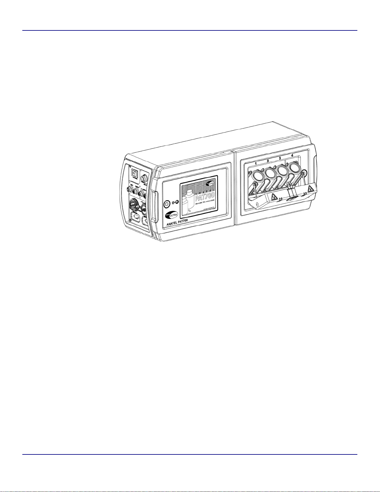
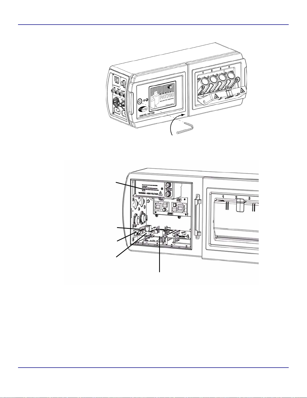
Figure 1-1 PAT700 with bottle bay open
Operator Manual Anatel
WGM - 26 July 2007 - Edition 01-d4
Page 13

PAT700 Total Organic Carbon Analyzer – Before You Begin Page 3
The reader/writer takes the data received from the tag and passes the information in digital
form to the PAT700 processor. The RFID system in the PAT700 can read and write to the
RFID tags attached to the standards bottle. The writing feature allows the PAT700 to write
data to the bottles showing that the bottle has been used and provides for writing of data for
the exclusive excursion sampling feature.
The RFID system in the PAT700 does not require any user intervention to operate. The
system operates automatically when bottle tests are performed. The system automatically
turns on and off to read and write data only when necessary. When enabled, the radio
frequency modulation emitted from the antennas is fixed at 13.56 Mhz. There are no user
serviceable parts associated with the RFID system. The RFID reader/writer board assembly
should only be serviced by a Hach Ultra certified service representative.
Since the RFID labels on the standards bottles contain the data necessary for each standard,
the labels must not be removed from the bottle. Without the label, the RFID reader/writer has
no data to read and will not operate as intended.
1.4 Reading and following instructions
You must comply with all instructions while you are installing, operating, or maintaining the
analyzer. Failure to comply with the instructions violates standards of design, manufacture,
and intended use of the analyzer. Hach Ultra disclaims all liability for the customer's failure to
comply with the instructions.
• Read instructions — Read all instructions before installing or operating the product.
• Retain instructions — Retain the instructions for future reference.
• Follow instructions — Follow all installation, operating and maintenance instructions.
• Heed warnings and cautions — Adhere to all warnings and caution statements on the
product and in these instructions.
• Parts and accessories — Install only those replacement p arts and acce ssories that are
recommended by Hach Ultra Analytics, Inc. Substitution of parts is hazardous.
1.5 Safety
• Read the Anatel PAT700 TOC Analyzer Operator Manual thoroughly before installing
or operating the analyzer. Although the analyzer is designed for rugged use, you
should care for and maintain it as described in this manual. Following proper safety
and handling instructions promotes accident free operation and prolong product life.
• For any questions regarding the analyzer, phone Hach Ultra at 800.866.7889 or
+1 541.472.6500.
• All service procedures should be conducted by properly trained service personnel.
• Follow all procedures in Return procedures, page 109 before shipping the analyzer to
a service center for repair or recalibration.
• Make sure the analyzer is properly installed and all connections are correctly installed
before operating the analyzer. Adhere to all instructions provided in caution and
warning statements.
• Any changes or modifications not expressly approved by Hach Ultra Analytics, Inc.
could void the user's authority to operate this equipment.
WGM - 26 July 2007 - Edition 01-d4
Anatel Operator Manual
Page 14

Page 4 Before You Begin – PAT700 Total Organic Carbon Analyzer
1.6 Caution and warning statements
This manual contains caution and warning statements with which you must comply to prevent
inaccurate measurement, property damage, or personal injury.
CAUTION
Caution statements alert you to hazards or unsafe practices that could result in minor
personal injury or property damage.
Each caution statement explains what you must do to prevent or avoid the potential result of
the specified hazard or unsafe practice.
WARNING
Warning statements alert you to hazards or unsafe practices that could result in
severe property damage or personal injury due to electrical shock, fire, or explosion.
Each warning statement explains what you must do to prevent or avoid the potential result of
the specified hazard or unsafe practice.
Caution and warning statements comply with American Institute of Standards Z535.1-2002
through Z535.5-2002, which set forth voluntary practices regarding the content and
appearance of safety signs, symbols, and labels.
Each caution or warning statement explains:
1) The specific hazard that you must prevent or unsafe practice that you must avoid,
2) The potential result of your failure to prevent the specified hazard or avoid the
unsafe practice, and
3) What you must do to prevent the specified hazardous result.
1.7 FCC conformance
The PAT700 contains a registered Radio Frequency device (RFID)
FCC ID: VICPAT700TOC
IC: 6149A-PT700TOC
Japan
Frequency: 13.56 Mhz - +/- 7Khz
RF Output power <180mW
WGM - 26 July 2007 - Edition 01-d4
Operator Manual Anatel
Page 15

P AT700 Total Organic Carbon Analyzer – Before You Begin Page 5
This equipment has been tested and found to comply with the limits for a Class B digital
device, pursuant to Part 15 of the FCC Rules. These limits are designed to provide
reasonable protection against harmful interference in a residential installation. This equipment
generates, uses and can radiate radio frequency energy and, if not installed and used in
accordance with the instructions, may cause harmful interference to radio communications.
However, there is no guarantee that interference will not occur in a particular installation. If
this equipment does cause harmful interference to radio or television reception, which can be
determined by turning the equipment off and on, you should try to correct the in terference by
one or more of the following measures:
• Reorient or relocate the receiving antenna.
• Increase the separation between the equipment and receiver.
• Connect the equipment into an outlet on a circuit different from that to which the
receiver is connected.
• Consult the dealer or authorized service person for help.
Any changes or modifications not expressly approved by Hach Ultra Analytics, Inc. could void
the user's authority to operate the equipment.
1.8 Definitions of terms
The following terms are used throughout this manual:
Conductivity. A measure of the ability to conduct current through water. Conductivity, very
low with high-purity deionized water, is the reciprocal of resistivity and is measured in
microsiemens per centimeter (μS/cm).
Megohm (M). A measurement of 1,000,000 ohms.
Microsiemens (μS). A unit of conductance in the metric system equivalent to one millionth of
-6
an ampere per volt (1 µS = 1 x 10
A/V).
Normalize. To make conform to a standard. In this case, the user performs calculations on
the raw data to produce a result in a standard unit of measure.
Organic. Organic chemicals, including carbon atoms in complex molecules, but not including
carbonate (CO
, HCO3, CO3) or cyanide (CN) related compounds. Oxygen is very common
2
in organics, and they almost always include hydrogen.
Oxidation. The loss of electrons by a chemical species, typically with oxygen. Organic
carbon, for example, oxidizes to carbon dioxide and water.
Parts per billion (ppb). A term used to report trace chemical analyses. It refers to the
concentration of the element or compound present within one billion parts of water. One
microgram per liter (µg/L) is equal to 1 ppb).
Resistivity. Resistance, measured in megohmcentimeters (M-cm), to the flow of electrical
current through high-purity water. Resistivity is a means of continuously measuring the
purity of the water and is the reciprocal of conductivity.
Temperature compensation. Conductivity and resistivity measurements normalized to
25 °C (77 °F) for reporting purposes. Normalized conductivity and resistivity
measurements reflect the values that would be reported at a sample temperature of 25 °C
(77 °F) using a model based on sodium chloride in water. Conductivity and resistivity of
electric current in water depend on the temperature of the water. The lower the
temperature, the lower the conductivity and the higher the resistivity.
WGM - 26 July 2007 - Edition 01-d4
Anatel Operator Manual
Page 16

Page 6 Before You Begin – PAT700 Total Organic Carbon Analyzer
Total organic carbon (TOC). A measurement of the organics present in water based on its
carbon content. High-purity water measures TOC in parts per billion (ppb). Total organic
carbon is used interchangeably with total oxidizable carbon.
VGA. Video Graphics Adapter.
1.9 Customer service
For customer service:
• Voice: US: 1.970.663.9760 or 1.800.373.0531
EU: 41.22.594.6400
• FAX: US: 1.970.663.9761
EU: 41.22.594.6488
• Support hot line: US: 1.877.4 ANATEL (1.877.426.2835)
•Email: www.hachultra.com
Operator Manual Anatel
WGM - 26 July 2007 - Edition 01-d4
Page 17

P AT700 Total Organic Carbon Analyzer – Installation Page 7
Chapter 2 Installation
2.1 Installation requirements
Install the analyzer in a dry, dust-free environment. The analyzer has a splash-resistant
NEMA 12-compliant water resistant IP56 enclosure surrounding the electronics portion of the
analyzer. All components in the hydraulics portion of the analyzer are rated IP56.
• Install the analyzer in a properly ventilated location where ambient air temperature
does not exceed 35 °C (95 °F).
• The analyzer has 3/4-inch NPT conduit fittings or quick-connect fittings for wiring.
See Figure 2-1, page 8 for mounting dimensions. The analyzer weighs 27 lb (12.25 kg).
The analyzer ship kit includes the following parts:
• This instruction manual
• 5-foot (1.5 meter) PFA inlet tubing
• 10-foot (3 meter) polypropylene outlet tubing
• Allen wrench
•Stylus
• Instrument screwdriver
• RFID tagged excursion sample bottle
For units with quick connect I/O fittings the following items are also included:
• Quick connect power cord
• Male 8-pin quick connect cord fitting
• Three male 5-pin quick connect cord fitting
2.2 Orientation and mounting
CAUTION
Failure to mount the analyzer in an upright position can cause measurement error.
To ensure proper operation of the measurement cell between analysis cycles, mount the
analyzer in an upright position. See Figure 2-2.
• Secure the analyzer using the factory-supplied mounting bracket (see Figure 2-3,
page 10). Use the mounting holes in the bracket to mount it to a flat, stable surface.
• Hook the analyzer onto the mounting bracket and latch it into place using the twist
latches.
• An optional handle, attached to the analyzer, enables it to be moved from place to
place.
WGM - 26 July 2007 - Edition 01-d4
Anatel Operator Manual
Page 18
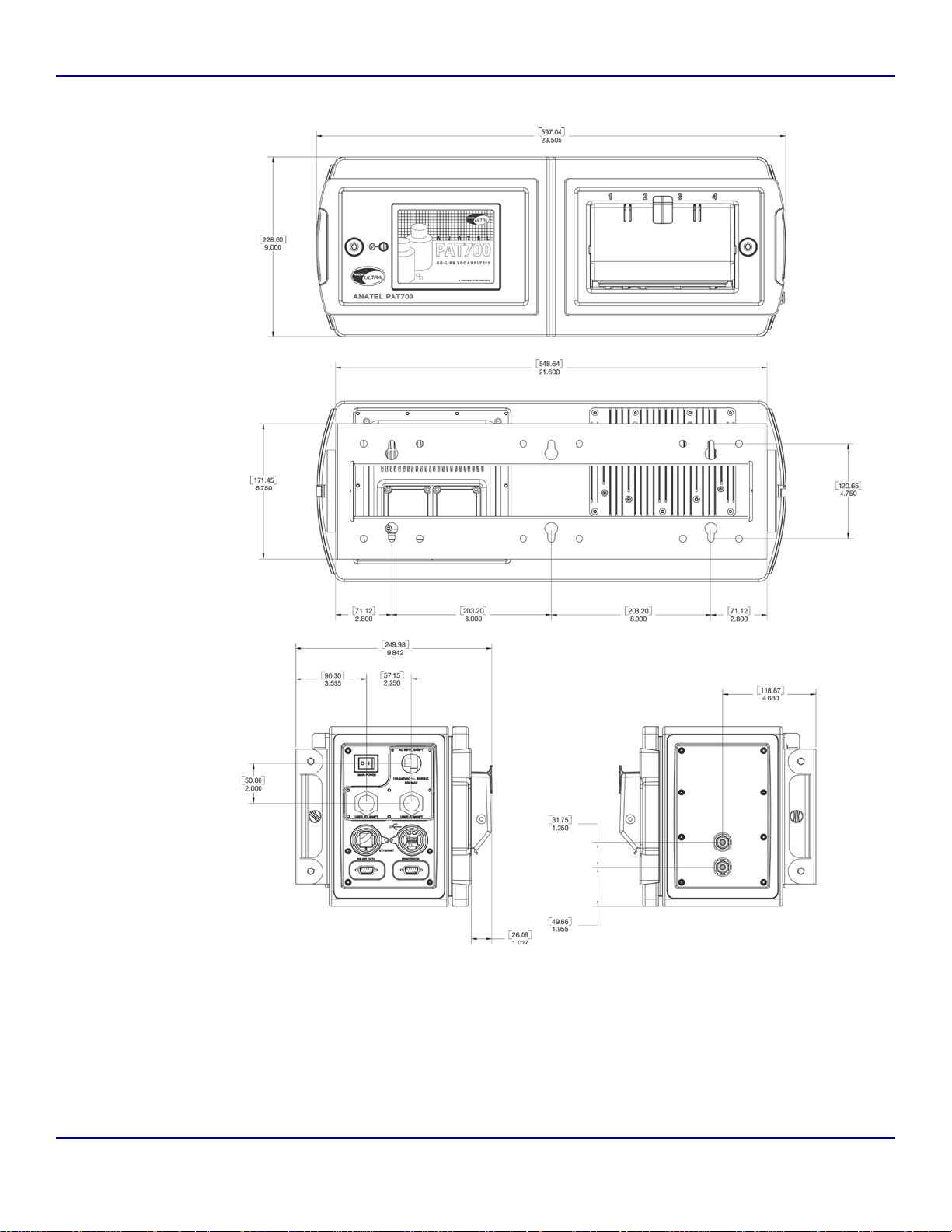
Page 8 Installation – PAT700 Total Organic Carbon Analyzer
Figure 2-1 PAT700 mounting dimensions
Operator Manual Anatel
WGM - 26 July 2007 - Edition 01-d4
Page 19
P AT700 Total Organic Carbon Analyzer – Installation Page 9
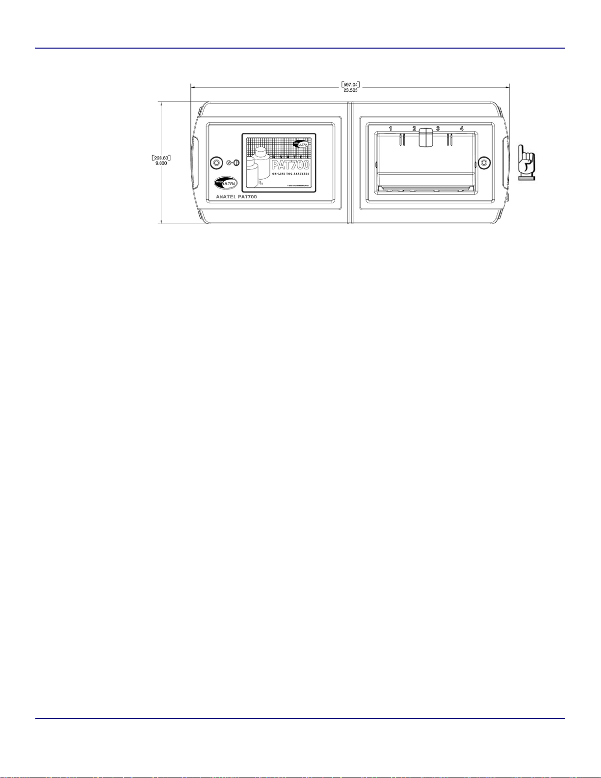
Figure 2-2 PAT700 analyzer orientation
Mounting general considerations
Follow these guidelines when installing the analyzer:
• Locate the analyzer where it is accessible for operation, service and calibration.
• Minimize the distance between the water system sample point and the analyzer to
allow for representative sampling.
• Locate the analyzer where the ambient temperature remains between 15 and 35 °C
(59 and 95 °F).
• The transmitter mounting bracket is installed independently from the analyzer. Once
mounted, the analyzer hooks on the mounting bracket and locks into place with twist
latches.
• Mount the transmitter mounting bracket to a stable, flat surface or dual instrument
poles.
• The front of the analyzer requires 12 inches (30.48 cm) of clearance to allow the doors
to open completely.
• The analyzer is available with ¾-inch conduit openings or quick-connect fittings for
power and I/O wiring. If conduit is used, install fittings that ensure a complete seal with
the openings and are properly sealed to keep the analyzer electronics compartment
watertight.
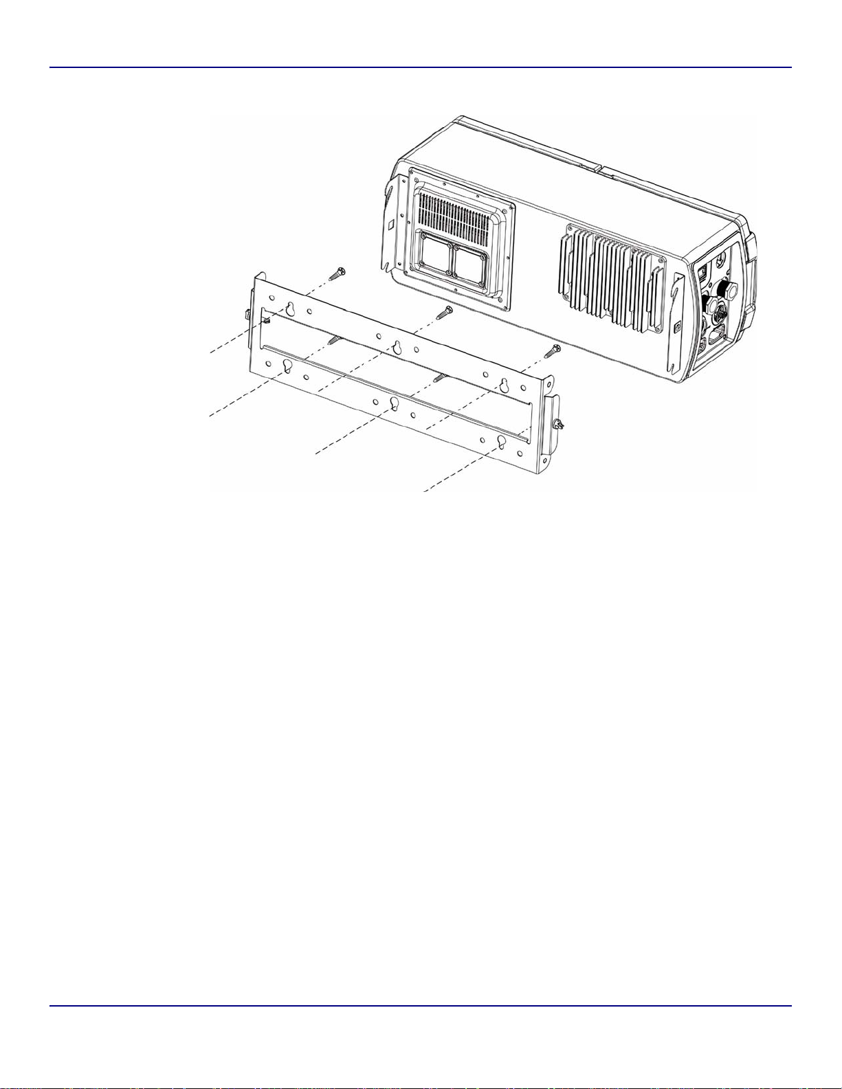
Mounting to a wall
Follow these guidelines and refer to Figure 2-1 and Figure 2-3 to mount the transmitter to a
wall or other flat, rigid surface:
• Use 5/16-inch (8 mm) diameter screws or bolts and nuts to mount the analyzer to a
wall or other flat, rigid surface. Use hardware that can withstand the process
environment. Hach Ultra does not supply hardware.
• To minimize stress on the analyzer mounting bracket, secure all mounting bolts to the
same structure, which should be flat and should not vibrate or move excessively. Do
not secure bolts to separate girders, beams, or wall studs, which can move
independently.
WGM - 26 July 2007 - Edition 01-d4
Anatel Operator Manual
Page 20
Page 10 Installation – PAT700 Total Organic Carbon Analyzer
Figure 2-3 PAT700 wall mount
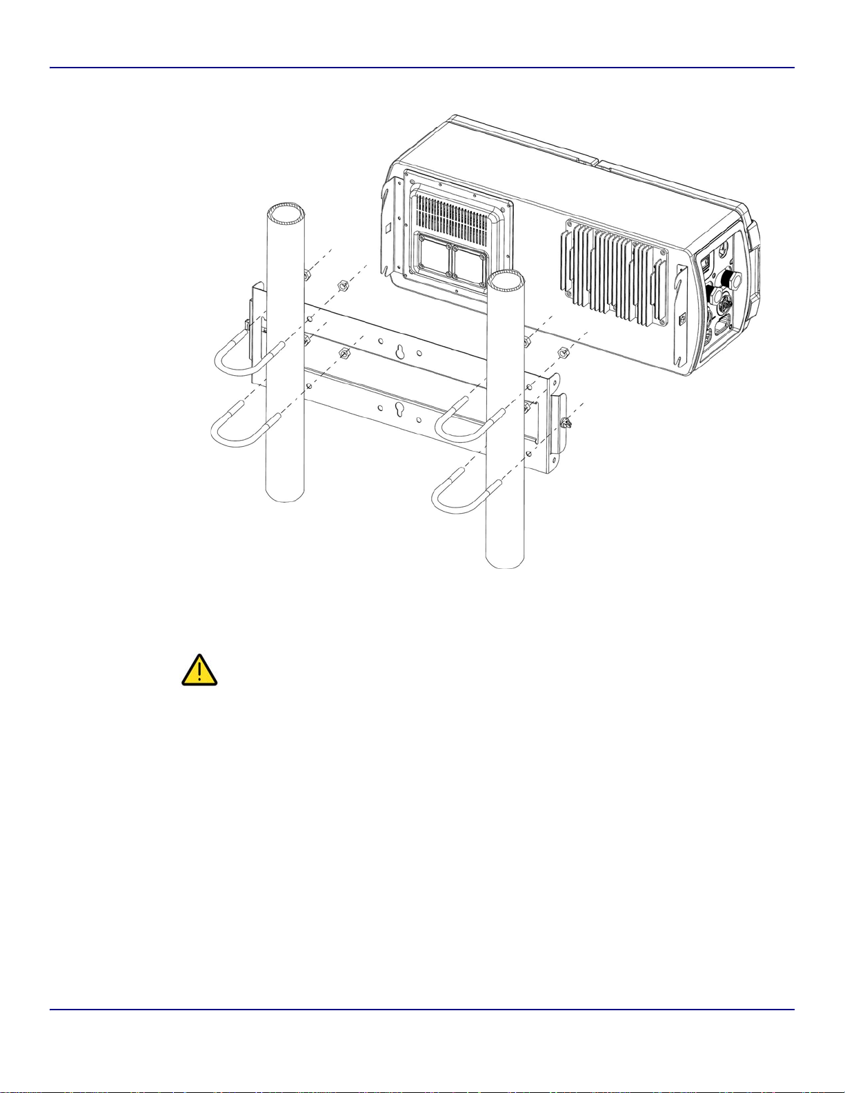
Mounting to dual instrument poles
Follow these guidelines and refer to Figure 2-1 and Figure 2-4 to mount the transmitter to
instrument poles:
• Mount the analyzer mounting bracket to two instrument poles that are attached to a
common surface. Do not secure to two instrument poles that could move
independently.
• Use four 5/16-inch U-bolts, two for each 2-inch pipe, and eight matching nut s, to mount
the analyzer mounting bracket to two rigid instrument poles. Use U-bolts and nuts that
can withstand the process environment. Hach Ultra does not supply U-bolts or nuts.
• The instrument poles should extend at least 10 inches (254 mm) from a common rigid
base and should be no larger than 2 inches (50.8 mm) in diameter.
Operator Manual Anatel
WGM - 26 July 2007 - Edition 01-d4
Page 21
P AT700 Total Organic Carbon Analyzer – Installation Page 11
Figure 2-4 PAT700 instrument-pole mount
2.3 Plumbing connections
CAUTION
Improper plumbing connections to the analyzer can cause improper flow through the
analyzer, resulting in measurement error.
To avoid measurement error due to improper flow if temperature and pressure exceed the
limits listed in Table 2-1, page 12, install high grade 1/4” (OD) PTFE, FEP, PVDF, or 316
stainless steel tubing. Otherwise, install the factory-supplied 1/ 4” PFA (perfluoroalkoxy resin)
sample tubing and 1/4” OD polypropylene drain tubing. Hach Ultra supplies 5 feet (1.5 meters)
of PFA tubing and 10 feet (3 meters) of polypropylene tubing with the analyzer.
WGM - 26 July 2007 - Edition 01-d4
Anatel Operator Manual
Page 22
Page 12 Installation – PAT700 Total Organic Carbon Analyzer
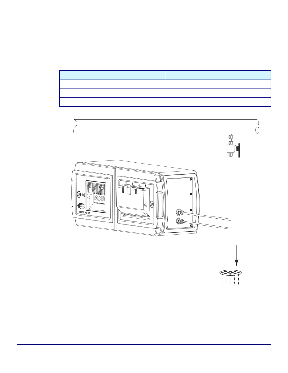
Isolation valve
To enable manual isolation of the analyzer from input flow, connect the analyzer to the sample
supply through a customer-supplied upstream isolation valve. See Figure 2-5.
Table 2-1 Maximum temperature and pressure limits for PFA tubing
Maximum water temperature Maximum pressure
75 °C (167 °F) 90 psig (620 kPa)
85 °C (185 °F) 80 psig (550 kPa)
90 °C (194 °F) 70 psig (480 kPa)
Figure 2-5 PAT700 connection to isolation valve
Operator Manual Anatel
WGM - 26 July 2007 - Edition 01-d4
Page 23
P AT700 Total Organic Carbon Analyzer – Installation Page 13
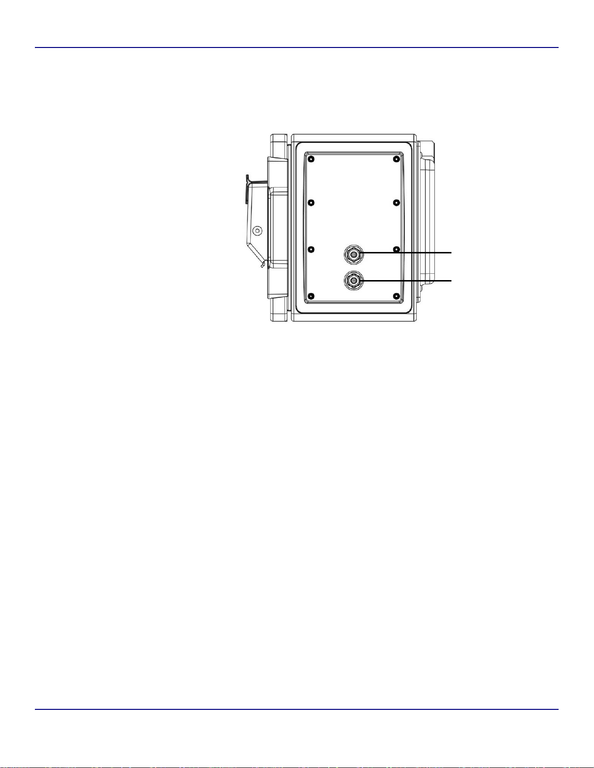
Water inlet and outlet
Tubing connects to the 1/4” inlet (WATER IN) and outlet (WATER OUT) 316 stainless steel
compression fittings on the analyzer. See Figure 2-6. Installation requires a 7/16” wrench.
A
B
A Water inlet
B Water outlet
Figure 2-6 PAT700 water inlet and outlet connections
To connect plumbing to the 1/4” inlet (WATER IN) port, follow these steps:
1) To avoid introducing debris through the inlet plumbing, flush the isolation valve by
opening and closing it fully several times.
2) T aking care not to crimp or da mage the tubing, push one end of the inlet tubing into
the water inlet port until it cannot be inserted any farther.
3) Taking care not to pull on the tubing, hand-tighten the compression nut.
4) Mark both the compression nut and the WATER IN connector as a reference for
tightening the nut.
5) Tighten the compression nut 1-1/4 turns to secure the connection.
WGM - 26 July 2007 - Edition 01-d4
Anatel Operator Manual
Page 24

Page 14 Installation – PAT700 Total Organic Carbon Analyzer
CAUTION
Over tightening fittings can damage the ferules, causing leaks that can result in
measurement error or property damage.
After tightening a ferule 1-1/4 turns, do not tighten it more than another 1/4 turn to seal the
connection.
To connect plumbing to the 1/4” outlet (WATER OUT) port, follow these steps:
1) Noting the flow direction, attach the 10-foot long, 1/4” OD polypropylene drain
tubing to the WATER OUT port of the analyzer.
2) Taking care not to crimp or damage the tubing, push one end of the tubing into the
water outlet port until it cannot be inserted any farther.
3) Taking care not to pull on the tubing, hand-tighten the compression nut.
4) Mark both the compression nut and the WATER OUT connector as a reference for
tightening the nut.
5) Tighten the compression nut 1-1/4 turns to secure the connection.
6) Leak test the connections by slowly opening the upstream isolation valve to
introduce water into the analyzer. Pulse the valve several times by opening and
closing it, then recheck the fittings.
7) If necessary, slowly tighten the compression fittings to stop any leaks.
2.4 Wiring connections for PAT700 with conduit openings
Refer to this section if the PAT700 has three 3/4-inch female NPT conduit openings.
• One opening accommodates power supply wiring.
• The other two openings accommodate 4-20 mA or discrete I/O wiring.
• Power supply and I/O wiring connects to terminals in the compartment behind the
analyzer’s display unit. Figure 2-8 illustrates power supply and I/O wiring terminals. To
access the terminals:
1) Use the factory-supplied Allen wrench to unlatch the door that contains the display.
2) Unlatch the door and swing it open on its hinges.
Operator Manual Anatel
WGM - 26 July 2007 - Edition 01-d4
Page 25
P AT700 Total Organic Carbon Analyzer – Installation Page 15
Figure 2-7 Using Allen wrench to access wiring connections
A
B
C
D
E
A Power supply wiring compartment (terminals are behind door)
B 4-20 mA output wiring terminals (connector block J17)
C Discrete input wiring terminals (connector block J24)
D Discrete output wiring terminals (connector block J22)
E I/O circuit board
Figure 2-8 PAT700 power supply and I/O wiring terminals
WGM - 26 July 2007 - Edition 01-d4
Anatel Operator Manual
Page 26
Page 16 Installation – PAT700 Total Organic Carbon Analyzer
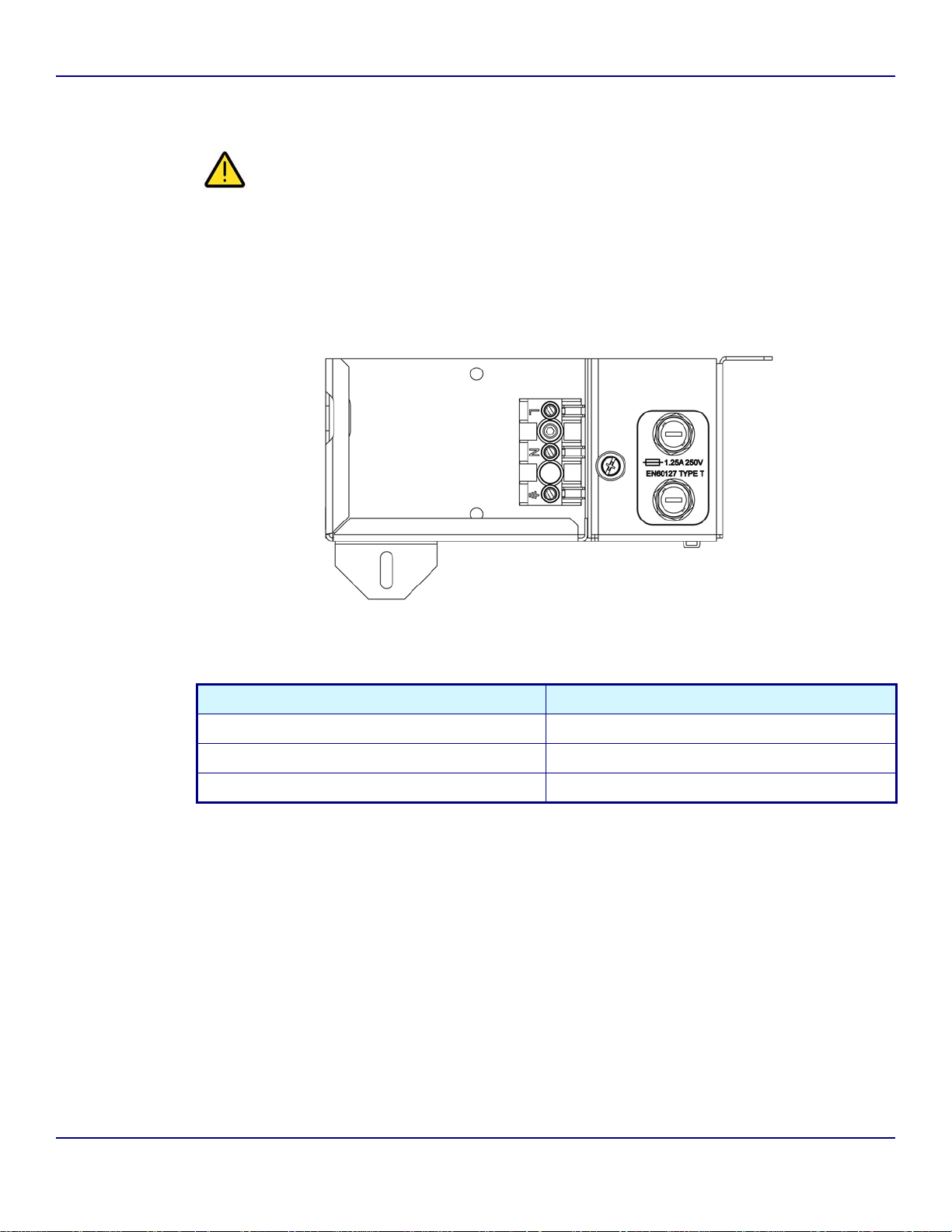
Power supply wiring
WARNING
Improper grounding can cause property damage or personal injury.
• Adhere to ground network requirements for the facility.
• Maintain all exposed conductors at earth ground.
Figure 2-9 illustrates power supply wiring terminals.
Table 2-2 lists specifications for power supply wiring.
Figure 2-9 PAT700 power supply wiring terminals
Table 2-2 Power supply wiring specifications
Description Specification
Voltage input 100 to 240 VAC universal
Frequency 50 to 60 Hz
Power 900 Watts maximum, 1.25 A @ 250 VAC
I/O wiring
The analyzer has three 4-20 mA outputs, two discrete inputs, and four discrete outputs.
Connect wiring to the Y-shaped connector blocks located on the I/O circuit board.
• The connector blocks are a 2-part assembly.
• The terminal block connector can be unplugged from the analyzer for easier
installation of wiring.
2
• Install twisted-pair unshielded wiring, 18 to 14 AWG (1.0 to 2.5 mm
).
Operator Manual Anatel
WGM - 26 July 2007 - Edition 01-d4
Page 27

P AT700 Total Organic Carbon Analyzer – Installation Page 17
4-20 mA outputs
The analyzer has three 4-20 mA outputs. Wiring connects to terminals on connector block
J17, as listed in Table 2-3.
• Analog output 1 represents TOC (total organic carbon).
• Analog output 2 represents conductivity or resistivity (user selected).
• Analog output 3 represents temperature in °F or °C (user selected).
Table 2-3
J17 Block Terminal Description Variable Designation
J17 connector block: 4-20 mA output wiring terminal designations
1 4-20 mA source output for analog output 1 (+) TOC AO1+
2 4-20 mA sink output for analog output 1 (–) TOC AO13 4-20 mA source output for analog output 2 (+) Conductivity or resistivity AO2+
4 4-20 mA sink output for analog output 2 (–) Conductivity or resistivity AO25 4-20 mA source output for analog output 3 (+) Temperature AO3+
6 4-20 mA sink output for analog output 3 (–) Temperature AO3-
Discrete inputs
The analyzer has two discrete inputs. Wiring connects to terminals on connector block J24, as
listed in Table 2-4.
• Discrete input 1 initiates TOC analysis. When the output state switches from high to
low, the ana lyzer stops the cu rrent operation and runs a single T O C analysis. Aft er the
analysis is complete, the analyzer returns to the mode defined by digital in put 2. During
the TOC analysis, the analyzer ignores all subsequent trigger values.
• Discrete input 2 switches the analyzer modes. If digital output 2 is in high state, the
analyzer is in TOC mode. If digit al output 2 is in lo w state, the analyzer runs in flow with
conductivity mode.
Table 2-4 J24 connector block: Discrete input wiring terminal designations
J24 Block Terminal Description Variable Designation
1 Common connection for external sourcing (+) Common DI1/2+
2 Digital input 1 voltage source return input (–) Initiates TOC analysis DI1–
3 Digital input 2 voltage source return input (–) Analyzer mode DI2–
4 • 12 VDC power supply +
• Connect only if output device requires
power supply
5 • 12 VDC power supply –
• Connect only if output device requires
power supply
WGM - 26 July 2007 - Edition 01-d4
Output power supply +12V
Output power supply GND
Anatel Operator Manual
Page 28

Page 18 Installation – PAT700 Total Organic Carbon Analyzer
Discrete outputs
The analyzer has four discrete outputs. Wiring connects to terminals on connector block J22,
as listed in Table 2-5.
• Discrete output 1 is a TOC alarm. The output reports the TOC level as above (low
state) or below (high state) the user-specified alarm limit.
• Discrete output 2 is an uncompensated conductivity alarm. A low state indicates the
conductivity level is above the alarm limit. A high state indicates the conductivity level
is below the alarm limit.
• Discrete output 3 reports a warning or failure condition. A low state indicates an error
condition exists. A high state indicates no error conditions exist.
• Discrete output 4 reports a TOC analysis start (by indicating the state of the sample
inlet valve). A low state indicates the sample valve is closed. A high state indicates the
sample valve is open.
Table 2-5
J22 Block Terminal Description Variable Designation
J22 connector block: Discrete output wiring terminal designations
1 Digital output 1 (+) TOC alarm D O1+
2 Digital output 2 (+) Uncompensated
conductivity alarm
3 Common return for discrete outputs 1 and 2 (+) TOC alarm,
uncompensated
conductivity alarm
4 Digital output 3 (+) Warning or failure DO3+
5 Digital output 4 (+) TOC analysis start DO4+
6 Common return for discrete outputs 3 and 4 (+) Warning or failure,
7 • 12 VDC power supply +
• Connect only if input device requires power supply
8 • 12 VDC power supply –
• Connect only if input device requires power supply
TOC analysis start
Input power supply +12V
Input power supply GND
DO2+
DO1/2
DO3/4
2.5 Wiring connections for PAT700 with quick-connect fittings
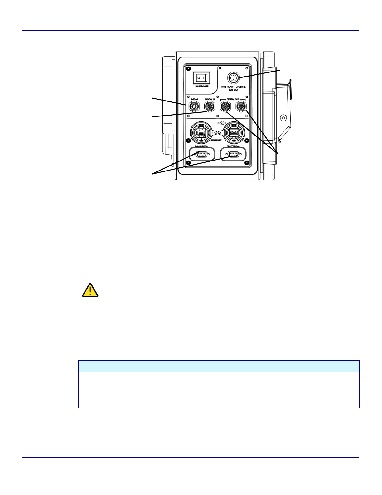
Refer to this section if the PAT700 has five quick-connect fittings, as illustrated in Figure 2-10.
• One connector accommodates power supply wiring.
• The other four connectors accommodate 4-20 mA or discrete I/O wiring.
• The comes with factory-supplied mating connectors and a plug-in cord for power
supply wiring.
Operator Manual Anatel
WGM - 26 July 2007 - Edition 01-d4
Page 29
P AT700 Total Organic Carbon Analyzer – Installation Page 19
D
A
B
E
C
A 4-20 mA output wiring connector
B Digital input wiring connector
C Serial communications wiring connectors (see page 22)
D Power supply wiring connectors
E Digital output wiring connectors
Figure 2-10 PAT700 power supply and I/O wiring terminals
Power supply wiring
WARNING
Improper grounding can cause property damage or personal injury.
• Adhere to ground network requirements for the facility.
• Maintain all exposed conductors at earth ground.
Table 2-6 lists specifications for power supply wiring.
Table 2-6 Power supply wiring specifications
Description Specification
Voltage input 100 to 240 VAC universal
Frequency 50 to 60 Hz
Power 900 Watts maximum, 1.25 A @ 250 VAC
WGM - 26 July 2007 - Edition 01-d4
Anatel Operator Manual
Page 30
Page 20 Installation – PAT700 Total Organic Carbon Analyzer
I/O wiring
The analyzer has three 4-20 mA outputs, two discrete inputs, and four discrete outputs.
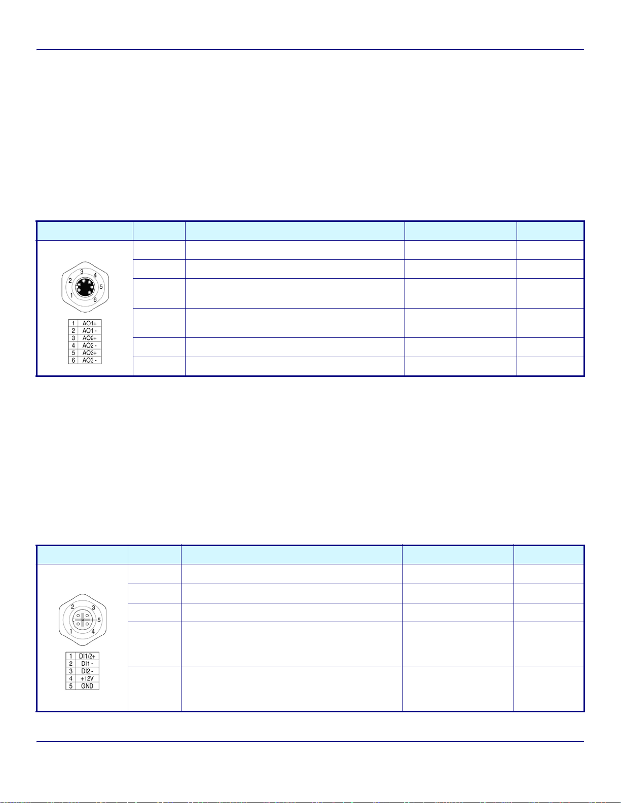
4-20 mA outputs
The analyzer has three 4-20 mA outputs, as listed in Table 2-7.
• Analog output 1 represents TOC (total organic carbon).
• Analog output 2 represents conductivity or resistivity (user selected).
• Analog output 3 represents temperature in °F or °C (user selected).
Table 2-7 4-20 mA output wiring terminal designations
Wiring connector Terminal Description Variable Designation
1 4-20 mA source output for analog output 1 (+) TOC AO1+
2 4-20 mA sink output for analog output 1 (–) TOC AO1–
3 4-20 mA source output for analog output 2 (+) Conductivity or
resistivity
4 4-20 mA sink output for analog output 2 (–) Conductivity or
resistivity
5 4-20 mA source output for analog output 3 (+) Temperature AO3+
6 4-20 mA sink output for analog output 3 (–) Temperature AO3–
AO2+
AO2–
Discrete inputs
The analyzer has two discrete inputs, as listed in Table 2-8.
• Discrete input 1 initiates TOC analysis. When the output state switches from high to
low, the ana lyzer stops the cu rrent operation and runs a single T O C analysis. Aft er the
analysis is complete, the analyzer returns to the mode defined by digital in put 2. During
the TOC analysis, the analyzer ignores all subsequent trigger values.
• Discrete input 2 switches the analyzer modes. If digital output 2 is in high state, the
analyzer is in TOC mode. If digit al output 2 is in lo w state, the analyzer runs in flow with
conductivity mode.
Table 2-8 Discrete input wiring terminal designations
Wiring connector Terminal Description Variable Designation
1 Common connection for external sourcing (+) Common DI1/2+
2 Digital input 1 voltage source return input (–) Initiates TOC analysis DI1–
3 Digital input 2 voltage source return input (–) Analyzer mode DI2–
4 • 12 VDC power supply +
• Connect only if output device requires power
supply
5 • 12 VDC power supply –
• Connect only if output device requires power
supply
Operator Manual Anatel
Output power supply +12V
Output power supply GND
WGM - 26 July 2007 - Edition 01-d4
Page 31

P AT700 Total Organic Carbon Analyzer – Installation Page 21
Discrete outputs
The analyzer has four discrete outputs, as listed in Table 2-9 and Table 2-10.
• Discrete output 1 is a TOC alarm. The output reports the TOC level as above (low
state) or below (high state) the user-specified alarm limit.
• Discrete output 2 is an uncompensated conductivity alarm. A low state indicates the
conductivity level is above the alarm limit. A high state indicates the conductivity level
is below the alarm limit.
• Discrete output 3 reports a warning or failure condition. A low state indicates an error
condition exists. A high state indicates no error conditions exist.
• Discrete output 4 reports a TOC analysis start (by indicating the state of the sample
inlet valve). A low state indicates the sample valve is closed. A high state indicates the
sample valve is open.
Table 2-9 Discrete outputs 1 and 2 wiring terminal designations
Wiring connector Terminal Description Variable Designation
1 Digital output 1 (+) TOC alarm DO1+
2 Digital output 2 (+) Uncompensated
conductivity alarm
3 Co mm o n re turn for discrete outputs 1 and 2 (–) TOC alarm,
uncompensated
conductivity alarm
4 • 12 VDC power supply +
• Connect only if input device requires power sup p ly
5 • 12 VDC power supply –
• Connect only if input device requires power sup p ly
Input power supply +12V
Input power supply GND
DO2+
DO1/2–
Table 2-10 Discrete outputs 3 and 4 wiring terminal designations
Wiring connector Terminal Description Variable Designation
1 Digital output 3 (+) Warning or failure DO3+
2 Digital output 4 (+) TOC analysis start DO4+
3 Common return for discrete outputs 3 and 4 (–) Warning or failure,
TOC analysis start
4 • 12 VDC power supply +
• Connect only if input device requires power supply
Input power supply +12V
DO3/4–
5 • 12 VDC power supply –
• Connect only if input device requires power supply
WGM - 26 July 2007 - Edition 01-d4
Input power supply GND
Anatel Operator Manual
Page 32

Page 22 Installation – PAT700 Total Organic Carbon Analyzer
2.6 Serial communication
The analyzer has the following serial ports:
• A female RS-232 serial port for data acquisition and control via a host computer.
• A male RS-232 serial port for connection to an external printer (1200 baud, 8 dat a bits,
1 stop bit, no parity).
• A USB port for data transfer via a FAT drive.
• An Ethernet
®
10/100 base-T interface port for communication via Modbus
For information about using Modbus protocol, see the instruction manual entitled Using
Modbus Protocol with the Anatel PAT700 TOC Analyzer.
• All serial ports are internally wired. Table 2-11 lists specifications for serial
communication.
Table 2-11 RS-232 serial communication specifications
Description Specification
RS-232 interface ports ASCII, 8 data bits, no parity, 1 stop bit, 1200 baud
USB host Output to FAT memory stick
Ethernet
®
interface • 10/100 base-T, Modbus® TPC
• 1 start bit, 8 data bits, 2 stop bits, no parity
®
protocol.
Serial interface commands consist of mode set, parameter set, data read, data logger and
data history functions. The commands consist of 2-character ASCII text mnemonics. Some
commands also require one or more arguments, each delimited by at least one space (ASCII
32; 20 Hex), followed by the command mnemonic. Each command string is terminated with a
carriage return (ASCII 13; 0D Hex).
The analyzer responds to uppercase or lowercase commands.
The analyzer responds with an OK> prompt after the command has been accepted. In
addition, Data read and parameter set commands elicit a reply that consists of one or more
numeric or text values, each delimited by at least one space, and terminated by a carriage
return, line feed pair (ASCII 13,10; 0D,0A
hex
).
Both commands and replies use a free field format, so the number of delimiting spaces and
length of each argument or data field may vary. If a command is rejected due to invalid syntax,
for instance, refusal is indicated by a question mark (ASCII63; 3F
) reply preceding the
hex
“OK>” prompt.
The notations used to represent command arguments below are as follows:
hh:mm:ss hours:minutes:seconds
n decimal number (such as “1.234”)
i integer (such as “1”)
s text string (such as “SENSOR_NAME”)
b binary flag (“1” or “0”)
Operator Manual Anatel
WGM - 26 July 2007 - Edition 01-d4
Page 33

P AT700 Total Organic Carbon Analyzer – Installation Page 23
Mode set commands
The mode set commands are used to determine the instrument’s operational mode.
Table 2-12 Mode set commands
Command Function Comment
MC Self-clean mode Valve open, lamp on
MD Auto TOC mode Continuous TOC analyses
ME Clear code log Erases codes from memory
MO i Start TOC analysis • One or more TOC analyses, then goes to idle state
• Default is one analysis cycle if an argument (“i”) is not specified
MP Purge mode • Valve open, lamp off
• Shows resistivity/conductivity and temperature
MZ Idle state Places analyzer in idle state (if present)
Parameter set commands
Issuance of the “HR” command displays or sets the user-defined parameters. When issued
without arguments, the analyzer’s current settings are displayed. Issued with arguments, the
specified parameters are changed for the analyzer and a printout is generated documenting
the modification. If an “out of bounds" value is sent, the entire command is ignored.
Issuing the “HR” command without specifying arguments displays the current parameter
settings. Read-only values cannot be modified.
WGM - 26 July 2007 - Edition 01-d4
Anatel Operator Manual
Page 34

Page 24 Installation – PAT700 Total Organic Carbon Analyzer
Table 2-13 Parameter set commands
Command Function
HR t t i i . . . Sample time (hh:mm:ss)
Cycle time (hh:mm:ss)
Absolute TOC alarm limit (ppb)
Reserved (always “0”)
Reserved (always “0”)
Analyzer channel ID number (1 through 8)
Analyzer name (1 through 13 characters)
Cycle modes (0 = TOC and idle, 1 = T OC and purge)
Sampling mode (0 = Water saver, 1 = Continuous)
Diagnostic port function (0 = Normal, 1 = External module)
Conductivity/resistivity units of measure:
0 = M
Ω-cm
1 = μS/cm
2 = M
Ω-cm uncompensated
3 = μS/cm uncompensated
20 mA output during TOC calibration (0 = Inactive, 1 = Active)
TOC mode print strategy (0 = Continuous, 1 = Paper saver)
Purge mode print strategy (0 = Continuous, 1 = Paper saver)
Active alarm type (0 = Absolute ppb, 2 = Absolute ppb and uncompensated conductivity alarm)
Analog output type (0 = 4 to 20 mA, 1 = 0 to 20 mA)
20mA output on alarm (0 = minimum value, 1 = unchanged, 2 = maximum value)
TOC mode paper saver percentage change (1 through 99)
Purge mode paper saver percentage change (1 through 99)
Purge Mode Interval Between Printouts (hh:mm:ss)
Zero-scale TOC range (ppb)
Full-scale TOC range (ppb)
User TOC calibration slope (read-only)
Digital control (0 = disabled, 1 = enabled)
Log (0 = Data and audit, 1 = Audit only)
User conductivity calibration slope (read-only)
Example: "HR 00:01:00 00:00:00 500 0 0 1 SENSOR_NAME 0 0 0 0 0 0 0 0 0 0 1 1 00:01:00 0 1000 1.0
0 20 5 95 0 1.0 <“
SY Set time (MM:DD:YY:hh:mm:ss format)
Example: "SY 03 04 1993 12 33 00 <cr>"
Operator Manual Anatel
WGM - 26 July 2007 - Edition 01-d4
Page 35

P AT700 Total Organic Carbon Analyzer – Installation Page 25
Data read commands
The data read functions return multiple values, the string terminated with a <cr><lf>.
If the analyzer is in an operational mode that does not generate a TOC result (modes 6
through 12), the TOC, TOC alarm percentage, TOC trend, profile (curve) type, and oxidation
time are not returned.
Data normally are returned only in response to issuance of the RD or RE commands. When
collecting data with a serial communications program such as Windows 95 Hyperterminal,
however, it is more convenient to have the data displayed automatically. This can be done
using the SA command, which then displays data whenever they are reported.
Table 2-14 Data read commands
Command Function Comment
RD Read analyzer data RD Read analyzer data returns one line of time stamped data from when the unit
RE Read analyzer codes Returns time stamped alarms, if any, since the last power-up or ME command
began oxidation: mm/dd/yyyy, hh:mm, mode, state, TOC in ppb, alarm
percentage, trend in ppb/hr, resistivity in M
(profile) type and oxidation time in seconds.
The mode is:
1 = Auto TOC
2 = Single TOC
3 = Digital TOC
4 = Sample Manual
5 = Manual
6 = Clean Mode
7 = Purge Mode
8 = Digital Purge
9 = Temperature Test
10 = Self-Calibrate
11 = Idle Mode
12 = Failure Mode
The state is:
1 = Idle
2 = Sample
3 = Oxidize
4 = Self-Calibrate
5 = Repurge
issued, one code per line: hh:mm:ss (time of first occurrence), alarm code,
number of occurrences and alarm description.
Ω-cm, temperature in °C, curve
Log commands
Log functions return information on the analyzer’s internal log.
Table 2-15 Log commands
Command Function Comment
LP Display log Displays the contents of the internal log. If any third character is appended to the
LU Report log usage Displays what percentage (0 to 100) of the internal log has been used.
WGM - 26 July 2007 - Edition 01-d4
command (such as “LPx”), the display is aborted.
Anatel Operator Manual
Page 36

Page 26 Installation – PAT700 Total Organic Carbon Analyzer
Data history commands
Data history commands return the results of the most recent calibration and validation
procedures performed on the analyzer.
Table 2-16 Data history commands
Command Function Comment
PC Conductivity calibration history Up to five calibrations are displayed
PT TOC calibration history Up to five calibrations are displayed
PS System suitability calibration
history
PV TOC validation history Up to five tests are displayed
Up to five tests are displayed
Operator Manual Anatel
WGM - 26 July 2007 - Edition 01-d4
Page 37

P AT700 Total Organic Carbon Analyzer – Startup Page 27
Chapter 3 Startup
3.1 Startup sequence
The analyzer goes through the following sequence on power up:
1) Splash window: The splash window appears at startup while the system checks
for the FAT driver, copies files, and launches the application.
2) Verify lamp monitor: After the system has initialized, it verifies that the lamp
monitor works by turning on the main lamp and ensuring a voltage is returned. The
analyzer needs to enable the lamp to warm up for a few seconds to ensure a valid
result.
3) Sample bottle check: The system checks to see if the bottles loaded in the sample
cartridge match the last known configuration. If the bottles contain RFID tags, the
analyzer reads the tags and compare them against the information stored in the
settings. If the RFID tag doesn’t match what’s stored in the settings, the settings is
updated with the new information and a warning is generated. If the settings list a
non-RFID tagged bottle in one of the bottle positions and an RFID tag cannot be
detected in that position, the analyzer assumes the bottle is still present.
4) Start sampling: If the analyzer is configured to one of the Auto TOC modes, it
starts sampling after it has powered up.
5) Print header: After the system has started up, it prints a header that tells when the
system was rebooted, and its condition. It prints the column header for the normal
operation mode.
3.2 Logging on and off the analyzer
Lock and unlock icons
The lock and unlock icons enable you to sign on or sign off the analyzer.
If you are signed on to the system, touching the lock icon signs you off and changes the icon
to the unlock icon.
If no one is signed on to the system, touching the unlock icon displays the sign on dialog box.
• If you are signed on remotely, you cannot be signed off locally.
• If you are signed on locally, you cannot be signed off by a remote user.
Upon successfully signing on to the system locally, the icon changes to the sign off icon. Upon
successfully signing on to the system remotely, the icon changes to indicate that someone is
logged on remotely.
WGM - 26 July 2007 - Edition 01-d4
Anatel Operator Manual
Page 38

Page 28 Startup – PAT700 Total Organic Carbon Analyzer
Auto logoff
The analyzer logs the current user off after the user-defined period of time.
• If the analyzer is currently displaying the home screen, the lock or unlock icon in the
sliding toolbar changes to the sign on icon.
• If the analyzer is currently displaying any dialog box other than the home screen, the
sign on dialog box is displayed, forcing you to sign back on.
• Only the previously signed on user or the administrator may unlock the system.
3.3 Home screen
The home screen enables you to navigate through the menu system. The home screen
consists of a sliding toolbar for navigation; a data section to view the last data readings, view
a log of past data readings, or a graph of past data readings; a display of the current date and
time; a display of the current sampling mode; and a process animation. See Figure 3-1.
Figure 3-1 Home screen
Sliding toolbar
The sliding toolbar consists of icons that enable you to navigate through the analyzer menu
structure or to access a single function. The toolbar is hidden off the home screen most of the
time. You may access the toolbar by touching the toolbar’s tab to slide it out onto the right
edge of the home screen. Selecting one of the icons, touching somewhere else on the h ome
screen, or touching the toolbar’s tab hides the toolbar again.
Toolbar icons
Run mode icon enables you to change the operating mode of the analyzer. Touching the
icon takes you to the run mode dialog box without interrupting the current sample.
Setup icon enables you to modify the settings of the analyzer. Touching the icon takes you
to the setup dialog box, which contains navigation icons, without interrupting the current
sample.
Operator Manual Anatel
WGM - 26 July 2007 - Edition 01-d4
Page 39

P AT700 Total Organic Carbon Analyzer – Startup Page 29
Bottle mode icon enables you to enter bottle mode. Touching the icon takes you to the bottle
mode dialog box without interrupting the current sample.
Alarm acknowledge icon enables you to review and acknowledge current or
unacknowledged alarms. If no alarms are present, the icon is gray. Touching the icon takes
you to the alarm review dialog box and displays all unacknowledged alarms without
interrupting the current sample.
Diagnostics icon enables you to check the health of the analyzer. Touching the icon takes
you to the diagnostics dialog box without interrupting the current sample. The icon changes
states to display warni ng conditions.
Data review icon enables you to view the information from the log file. Touching the icon
takes you to the data review dialog box without interrupting the current sample.
Sign on/off icon enables you to sign onto the analyzer to modify or change the operation, or
sign off of the analyzer to prevent changes, without interrupting the current samp le. If no user
is signed on, the sign on icon is present. Touching the icon when no one is signed on takes
you to the sign on dialog box, where you may enter your user ID and password. If you are
already signed on, the sign off icon is present. Touching the icon when you are signed on
signs you off. While you are logged off, you have view-only access to all dialog boxes except
user security, factory setup, and audit trail. but you can issue print commands.
Home screen data views
Home screen data views consist of a display with current, log view, and graph tabs. You may
switch from tab to tab without interrupting the current sample. See Figure 3-2.
Figure 3-2 Home screen data views
WGM - 26 July 2007 - Edition 01-d4
Anatel Operator Manual
Page 40

Page 30 Startup – PAT700 Total Organic Carbon Analyzer
Date and time displays the current date and time in ISO format. Depending on the current
time format setting, the date and time is in 24-hour format (yyyy-mm-dd hh:mm:ss) or 12-hour
format (yyyy-mm-dd hh:mm:ss AM/PM). The date and time are set in the setup dialog box.
Bottle displays the current state of the bottles in the sample cartridge. There are three states
for this indicator (no bottles loaded, bottles loaded, or bottles empty). Touching this graphic
takes you to the bottle mode dialog box.
Status indicator displays the current alarm status.
• Green indicates the analyzer is operating properly.
• Yellow indicates the analyzer has experienced a warning condition.
• Red indicates the analyzer has experienced an error or alarm condition.
• Flashing red indicates the analyzer has experienced a fatal error.
Current tab
The home screen displays the last reading for TOC or conductivity, depending on the selected
analysis mode. In all modes except standby, conductivity and clean, the current tab displays
the last readings for TOC, conductivity, temperature, curve type, and the time of the last
reading. It displays the current analysis state and trend for TOC readings. See Figure 3-3.
Figure 3-3 Home screen current tab
Process animation displays the current state of the analysis as an animated graphic. There
are four possible states: idle, flushing, analyzing, reporting, and error conditions. Analysis
results are displayed until a new analysis is complete. It displays the last readings for
conductivity, temperature, and the time of the last reading. It displays the current state as
flushing.
Operation mode displays the selected mode of the analyzer. The choice s for operation mode
are online TOC, conductivity, standby, offline, and online manual TOC in upp er le ft co rner o f
home screen.
Analysis state displays the current state (idle, flushing, analyzing, or reporting) in text.
TOC displays the last TOC reading as “TOC: X.X ppb”. The range of this value is 0.5 to 2000
ppb. If the value exceeds 2000, “Over limit” is displayed.
Operator Manual Anatel
WGM - 26 July 2007 - Edition 01-d4
Page 41

P AT700 Total Organic Carbon Analyzer – Startup Page 31
Conductivity displays the last conductivity reading as “Conductivity: X.XX µS/cm” for
compensated conductivity and “Conductivity: X.XX µS/cm U” for uncompensated
conductivity. If resistivity is selected, it is displayed as “Resistivity: X.XX M-cm” for
compensated resistivity. The home screen displays conductivity or resistivity, depending on
the current setting of the display units set in the setup dialog box.
Temperature displays the last temperature reading in “Temperature: X.X °C” or
“Temperature: X.X °F”, depending on the current setting of the temperature units set in the
setup dialog box.
Timestamp displays the t ime of the last reading as “Timestamp: hh:mm:ss” in 24-hour forma t.
Trend displays the TOC trend over the last hour as “Trend: +/-X ppb/hr”.
Curve type displays the curve type for the last TOC reading as “Curve Type: X” where X can
be one of four types (P1, P2, or P3).
Log view tab
The log view tab displays all analysis readings or events as they would appear on the printout.
The log view displays all data since the analyzer was powered on up to the la st 72 hours. See
Figure 3-4.
Figure 3-4 Home screen log view tab
WGM - 26 July 2007 - Edition 01-d4
Anatel Operator Manual
Page 42

Graph tab
The graph tab displays past data values. In all modes except conductivity, the graph displays
TOC values. In conductivity mode, the graph displays averaged conductivity values. These
values is averaged over the last 30 minutes. See Figure 3-5.
Figure 3-5 Home screen graph tab
Scroll icons move the graph cursor one point to the left or right.
Data values text label displays the TOC value, conductivity, temperature, timestamp, trend,
and curve type for the current cursor position.
Operator Manual Anatel
WGM - 26 July 2007 - Edition 01-d4
Page 43

P AT700 Total Organic Carbon Analyzer – Run modes Page 33
Chapter 4 Run modes
4.1 The analysis cycle
An analysis cycle is comprised of a flush of the analysis cell, oxidation, and idle time (if the
cycle time is greater than the combined flush and oxidation time).
Oxidation time varies based on the amount of total organic carbon in the sample. Flush time
is fixed and idle time varies to allow for varying analysis cycle time. See Figure 4-1.
Idle time occurs only after an online TOC analysis has been completed and only if the elapsed
time has not exceeded the value for cycle time.
• If conductivity was selected during idle, the analyzer reports conductivity during the idle
time.
• If no conductivity was selected, the analyzer verifies the lamp is off and opens the
bypass valve.
Figure 4-1 The TOC analysis cycle
WGM - 26 July 2007 - Edition 01-d4
Anatel Operator Manual
Page 44

Page 34 Run modes – PAT700 Total Organic Carbon Analyzer
CAUTION
Using the sample pump on a pressurized system could damage the pump.
Do not use the pump on a pressurized system.
In online TOC mode, the cell valve opens to flush the cell.
• If you are sampling from a zero pressure system, you need to enable the pump option
to draw water into the cell. In this case, the pump valve must be opened and the pump
started for every action that requires drawing water through the cell. The analyzer
continues to flush until the elapsed time is equal to the time value that has been set in
the setup dialog box. The cell valve is then closed to capture the sample.
• The analysis is started and conductivity and temperature readings are fed into the TOC
algorithm. Conductivity is monitored until oxidation is complete.
• When oxidation is complete, the analyzer reports the results to the home screen and
the printer if connected. It then checks to see if the elapsed time is greater than or
equal to the value for cycle time in settings. If it is, the next online TOC analysis is
started. Otherwise, it enters the idle mode.
4.2 Conductivity mode
Figure 4-2 Conductivity mode
In conductivity mode, the analyzer starts by verifying the lamp is off and the cell valve is open
to flush the cell. The analyzer reports the current readings for conductivity and temperature to
the main display every time a new value is available. The reported value is an average of the
data for over the last two seconds. The average reading will also be sent to the printer, based
on the printout settings, and the data log.
Standby
In standby, the analyzer verifies the lamp is off and all the valves are open. Standby mode
must be terminated by switching to another mode.
Operator Manual Anatel
WGM - 26 July 2007 - Edition 01-d4
Page 45

P AT700 Total Organic Carbon Analyzer – Run modes Page 35
Offline
In offline mode, the analyzer verifies the lamp is off and the valves are closed.
4.3 Clean
Figure 4-3 Clean mode
In clean mode, the analyzer starts by setting the elapsed time to 0, opening the cell valve to
flush the cell, and turning the lamp on. If timed operation was selected for this mode, the
analyzer will display a countdown timer on the dialog box. Otherwise, the elapsed time is
displayed. A stop icon will also be displayed on this dialog box to enable you to terminate the
operation. The analyzer will remain in this state until the countdown timer reaches 0, you
manually stops the operation, or the analyzer is switched to another mode by sch edule or by
digital control. Touching the stop icon immediately returns you to the home screen and starts
operating in its normal mode.
WGM - 26 July 2007 - Edition 01-d4
Anatel Operator Manual
Page 46

Operator Manual Anatel
WGM - 26 July 2007 - Edition 01-d4
Page 47

PAT700 Total Organic Carbon Analyzer – Setup Page 37
Chapter 5 Setup
5.1 Setup dialog box
The setup dialog box enables you to navigate and change analyzer settings. Accessing this
dialog box does not interrupt the current operation. See Figure 5-1.
Bottles
5.2 TOC
The TOC icon enables you to modify the settings for the TOC operating mode. Any changes
are stored in the settings file and become the defaults.
General
Figure 5-1 Setup dialog box
Figure 5-2 TOC setup dialog box, general
WGM - 26 July 2007 - Edition 01-d4
Anatel Operator Manual
Page 48

Page 38 Setup – PAT700 Total Organic Carbon Analyzer
Flush time text box enables you to specify the amount of time to flush the cell prior to
beginning a TOC analysis. You may specify a time in hh:mm:ss format between 00:00:00 and
23:59:59. The default value is 00:01:00.
Cycle time text box enables you to specify the minimum amount of time to between
automatic TOC analyses. Any value less than the actual elapsed time causes the next
analysis to begin immediately. You may specify a time in hh:mm:ss format between 00:00:00
and 23:59:59. The default value is 00:00:00.]
Return icon returns you to the setup dialog box and saves the changes. Any changes are
noted in the audit trail. All changes take effect on the next change of state.
Options
Figure 5-3 TOC dialog box, options
Bypass flow during analysis checkbox enables you to enable or disable bypass flow. If
enabled, the bypass flow valve opens at the beginning of the flush. If disabled, this valve
remains closed. The default setting is enabled.
Control with digital inputs checkbox enables you to control the mode of the analyzer
through the use of two digital inputs. The default setting is disabled. If enabled, the analyzer
enters the mode defined by digital2.
• If digital2 is high, the analyzer enters online TOC analysis mode. If digital2 is low, the
analyzer enters conductivity mode.
• A high to low state transition on digital1 aborts the current operation and immediately
run a single TOC analysis. The analysis runs to completion regardless of whether
subsequent trigger values are received. Once the analysis is complete, the analyzer
return to the mode defined by digital2.
Use pump checkbox determines whether or not to use the pump for online sampling. You
may enable or disable this option. If enabled, the analyzer turns the pump on any time water
needs to be drawn from the online water source to the cell. If disabled, the analyzer does not
use the pump for this action. Due to the potential risk of damage to the pump by using it with
a positive touchure water source, enabling this option displays a message asking you to
confirm this choice. The default setting for this option is disabled.
WGM - 26 July 2007 - Edition 01-d4
Operator Manual Anatel
Page 49

PAT700 Total Organic Carbon Analyzer – Setup Page 39
Average results checkbox averages the last X TOC analyses. The averaged value is
displayed on dialog box and logged to the data log. The default value is disabled.
Number of values to average text box enables you to specify the number of values to use
in the average. You may enter a value between 2 and 50. The default value is 4.
Return icon returns you to the setup dialog box and saves the changes. Any changes are
noted in the audit trail. All changes take effect on the next change of state.
Idle
Figure 5-4 TOC dialog box, idle
Flow during idle option icons enables you to select what state the analyzer should enter
while waiting for the next analysis to begin. You may select without conductivity, with
conductivity, or none (default). If without conductivity is selected, the analyzer closes all
valves except the cell valve and does not report conductivity. If with conductivity is selected,
the analyzer closes all valves except the cell valve and reports conductivity and temperature
once per minute. If none is selected, the analyzer closes all valves and does not report
conductivity or temperature.
Return icon returns you to the setup dialog box and saves the changes. Any changes are
noted in the audit trail. All changes take effect on the next change of state.
WGM - 26 July 2007 - Edition 01-d4
Anatel Operator Manual
Page 50

Page 40 Setup – PAT700 Total Organic Carbon Analyzer
5.3 System
The system icon enables you to modify system settings for the analyzer.
General
Figure 5-5 System dialog box, general
Analyzer name text box enables you to specify the analyzer name used in the system. You
may enter between 1 and 13 alphanumeric or symbol characters. The default value is
“Sensor”.
Language drop down list box enables you to select the language to use for all you
interfaces. You may select from English, French, German, Italian, or Spanish.
• Selecting a different language changes the operating system setting in the registry.
When the system is rebooted, the new setting takes effect. The default selection is
English.
• For Japanese and Chinese translations, this control is disabled. In these cases, the
appropriate operating system must be loaded, which loads the appropriate user
interfaces.
Restore factory defaults icon enables you to reset all the system options back to their
factory defaults.
Return icon returns you to the setup dialog box and saves the changes. Any changes are
noted in the audit trail. All changes take effect on the next change of state.
Operator Manual Anatel
WGM - 26 July 2007 - Edition 01-d4
Page 51

PAT700 Total Organic Carbon Analyzer – Setup Page 41
Display
Figure 5-6 System dialog box, display
Date text box enables you to specify the date to be used in the system. You may enter any
valid date in “yyyy-mm-dd” format. The default value is 2007-01-01.
Time text box enables you to specify the time to be used in the system. You may enter any
valid time in “hh:mm:ss” or “hh:mm:ss tt” format. The format used is based on the selected
time format. The default value is 12:00:00.
Time format text box enables you to select the time format to be used in the system. You
may select from 12 or 24-hour format. Selecting one of the formats changes the value
displayed in the time box. The default selection is 24-hour format.
Temperature display drop down list box enables you to select the format for displaying
temperature values. You may select °C and °F. The default value is °C.
Conductivity display drop down list box enables you to select the format for displaying
conductivity values. You may select conductivity uncompensated µS/cm, conductivity
compensated µS/cm, or resistivity M-cm. The default value is conductivity uncompensated. If
the conductivity alarm option has been selected, this control is disabled.
Return icon returns you to the setup dialog box and saves the changes. Any changes are
noted in the audit trail. All changes take effect on the next change of state.
WGM - 26 July 2007 - Edition 01-d4
Anatel Operator Manual
Page 52

Page 42 Setup – PAT700 Total Organic Carbon Analyzer
Sounds
Figure 5-7 System dialog box, sounds
Sound selection drop down list box enables you to select one of the system sounds to be
associated with a certain alarm type. The default sounds are determined during development.
Test icon plays the selected sound for the corresponding alarm.
Volume slider controls the level of the volume. Moving the slider to the right increases the
volume and moving it to the left decreases the volume. The default setting is determined
during development.
Return icon returns you to the setup dialog box and saves the changes. Any changes are
noted in the audit trail. All changes take effect on the next change of state.
Network
Figure 5-8 System dialog box, network
WGM - 26 July 2007 - Edition 01-d4
Operator Manual Anatel
Page 53

PAT700 Total Organic Carbon Analyzer – Setup Page 43
TCP/IP address text box sets the TCP/IP address for the analyzer. You may specify a value
between 0 and 255 for each octet. The default value is 192.168.0.1.
Subnet mask text box sets the subnet mask for the analyzer. You may specify a value
between 0 and 255 for each octet. The default value is 255.255.255.0.
Default gateway text box sets the default gateway for the analyzer. You may specify a value
between 0 and 255 for each octet. The default value is blank.
DNS server text box sets the DNS server address for the analyzer. You may specify a value
between 0 and 255 for each octet. The default value is blank.
WINS server text box sets the WINS server address for the analyzer. You may specify a
value between 0 and 255 for each octet. The default value is blank.
DHCP check box enables you to enable or disable DHCP. When enabled, the TCP/IP
address, subnet mask, and default gateway entries are disabled. The default setting is
enabled.
MAC address label displays the MAC address for the analyzer.
Print icon enables you to print the current system settings. Touching this icon sends a
formatted report to the serial printer.
Return icon returns you to the setup dialog box and saves the changes. Any changes are
noted in the audit trail. All changes take effect immediately.
5.4 Alarms
The alarms icon enables you to enable or disable TOC and conductivity alarms on the
system.
Figure 5-9 Alarm dialog box
TOC alarm limit text box enables you to set the alarm limit for the TOC measurement. You
may enter a value between 0 and 3000. The default value is 50.
TOC enabled checkbox enables you to enable or disable the TOC alarm. If enabled, any
TOC reading that exceeds the value in the alarm limit box triggers a TOC alarm. If disabled,
no TOC alarms are triggered. The default setting is disabled.
WGM - 26 July 2007 - Edition 01-d4
Anatel Operator Manual
Page 54

Page 44 Setup – PAT700 Total Organic Carbon Analyzer
Conductivity enabled checkbox enables you to enable or disable the conductivity alarm. If
enabled, any conductivity reading that exceeds the value in Table 2 Conductivity Alarm
Limits2 for the current temperature triggers a conductivity alarm. If disabled, no conductivity
alarms are triggered. The default setting is disabled. If you enable this alarm bu t do not have
uncompensated conductivity selected for conductivity display, refer to section Conductivity
display. A warning message is displayed asking if you want to change this value. Selecting
yes changes the conductivity display value and disable it, and enable the conductivity alarm.
Selecting no leaves the conductivity alarm checkbox unchecked.
Table 5-1 Conductivity alarm limits
Temperature
(°C)
0 0.6 55 2.1
5 0.8 60 2.2
10 0.9 65 2.4
15 1.0 70 2.5
20 1.1 75 2.7
25 1.3 80 2.7
30 1.4 85 2.7
35 1.5 90 2.7
40 1.7 95 2.9
45 1.8 100 3.1
50 1.9
Uncompensated
Conductivity
(µS/cm)
Temperature
(°C)
Uncompensated
Conductivity
(µS/cm)
Return icon returns you to the setup dialog box and saves the changes. Any changes are
noted in the audit trail.
Operator Manual Anatel
WGM - 26 July 2007 - Edition 01-d4
Page 55

PAT700 Total Organic Carbon Analyzer – Setup Page 45
5.5 Printer
The printer icon enables you to configure the printer settings for the analyzer.
TOC
Figure 5-10 Printer dialog box, TOC
Print TOC checkbox enables or disables the automatic printing of TOC data. The default
setting is enabled. If disabled, all other settings are also disabled.
TOC frequency radio buttons determine how frequently to print a TOC value. You may
select continuous or percent change. Selecting continuous generates a TOC printout at the
end of each analysis. This selection disables the percent change text box. Selecting percent
change generates a TOC printout only when the change in TOC level between successive
analyses exceeds the value in the percent change box. This selection enables the percent
change text box. The default setting is continuous.
Return icon returns you to the setup dialog box and saves the changes. Any changes are
noted in the audit trail.
WGM - 26 July 2007 - Edition 01-d4
Anatel Operator Manual
Page 56

Page 46 Setup – PAT700 Total Organic Carbon Analyzer
Conductivity
Figure 5-11 Printer dialog box, conductivity
Print during conductivity mode checkbox enables or disables the automatic printing of
data during conductivity mode. The default setting is enabled. If disabled, all o ther settings are
disabled.
Percent change text box appears on both the TOC and conductivity tabs but maintains the
same functionality. You may enter a value between 1 and 100%. The default value is 1.
Interval text box determines how often a printout occurs when in timed mode. You may enter
a value between 1 minute and 24 hours. The default value is 1 minute.
Conductivity frequency radio buttons determine how often to print a data during
conductivity mode. You may select timed or percent change. Selecting timed generates a
printout at the interval specified in the interval text box. This selection disables the percent
change text box. Selecting percent change generates a printout only when the change in
conductivity between successive analyses exceeds the value in the percent change box. T his
selection disables the Interval text box. The default setting is percent change.
Return icon returns you to the setup dialog box and saves the changes. Any changes are
noted in the audit trail.
Operator Manual Anatel
WGM - 26 July 2007 - Edition 01-d4
Page 57

PAT700 Total Organic Carbon Analyzer – Setup Page 47
5.6 Security
The security icon enables you to modify the security settings for the system.
General
Figure 5-12 Security settings dialog box, general
Enable security checkbox enables you to enable or disable the analyzer’s security system.
When enabled, you are required to sign on prior to making changes in the analyzer. When
disabled, you are not required to sign on. Disabling the analyzer’s security system disables
the audit trail and all controls on this dialog box except the enable data logging checkbox. The
default setting is disabled.
Enable data logging checkbox enables you to enable or disable data logging. When
enabled, all data are automatically stored to the analyzer’s internal data buffer. When
disabled, no data are saved. The default setting is enabled.
Password expiration text box enables you to set the number of days a user’s password may
be used before it must be changed. You may enter a value between 30 and 365 or 0. Entering
a 0 disables this feature. The default value is 60.
Password history text box enables you to set the number of passwords to keep in memory
to prevent a user from using an old password. You may enter a value between 0 and 5. The
default value is 3.
Automatic logoff text box enables you to set the number of minutes of inactivity before auto
logoff. You may enter a value between 0 and 60 minutes. A setting of 0 disables this feature.
The default value is 1.
Return icon returns you to the setup dialog box and saves the changes. Any changes are
noted in the audit trail.
WGM - 26 July 2007 - Edition 01-d4
Anatel Operator Manual
Page 58

Page 48 Setup – PAT700 Total Organic Carbon Analyzer
Users
Figure 5-13 Security settings dialog box, users
User rights. There are four different user types who can access the system: guest, operator,
administrator, and factory. Only operator users may be added or deleted from the system.
• Guest. This user type is any user who is not logged on to the system. This user may
access most areas and view information but is not allowed to modify any settings or
initiate any operations. Guests have no access to the security settings dialog box.
• Operator. This user type has full access to most dialog boxes. Operators have no
access to the security settings dialog box and read-only access to the factory dialog
box.
• Administrator. This user type has full access to most dialog boxes. Administrators
have read-only access to the factory dialog box.
• Factory. This user type has full access to all dialog boxes.
User list list box lists all users configured to use this analyzer. By default, two users appear
in the list (the administrator and the factory users). The default administrator entry has a user
name of “Administrator”, a user ID of “Admin”, and a password of “123456”. The default
factory entry has a user name of “Factory User”, a user ID of “Factory”, and a password of
“DIAMOND”. You may add up to 10 additional users to this list.
Add user icon enables you to add a user to the system. Touching this icon opens the edit
user dialog box.
Edit user icon enables you to edit an existing user in the system. You must first select a user
from the list. If no user is selected when this icon is touched, an error message appears.
Otherwise, the edit user dialog box appears. See Figure 5-14.
Return icon returns you to the setup dialog box and saves the changes. Any changes are
noted in the audit trail.
Operator Manual Anatel
WGM - 26 July 2007 - Edition 01-d4
Page 59

PAT700 Total Organic Carbon Analyzer – Setup Page 49
Edit user
Figure 5-14 Edit user dialog box
User full name text box enables you to type up to 15 alphanumeric or symbol characters.
The default value is blank.
Password enables you to type up to 1 5 alphanumeric or symbol characters. The default value
is blank.
• If the entered user ID and password match existing entries in the user’s list, you are
signed on and returned to the home screen.
• If the entered user ID and password don’t match existing entries in the user’s list, an
error message is displayed and you may try again.
Retype password text box enables you to verify the new password. This box is normally
disabled. You may enter a value between 5 and 15 alphanumeric or symbol characters. This
field is case sensitive. The default value is blank. When you enter a character, only the *
symbol appears for each key touch.
Change password checkbox forces you to change your password the next time you log on.
The default setting for this option is unchecked. Any time the password entry is modified, this
option is automatically checked.
OK icon returns you to the security settings dialog box and saves the changes. You ID and
user name must be unique. Any changes are noted in the audit trail.
• If a change was made to the password, both passwords in the password and confirm
password boxes must match. The new password may not be the same as any of the
passwords in the password history list.
• A changed password triggers an entry in the audit trail but does not list the old or new
password. The new password is converted to an MD5 hash. The new password and
date are added to the password history list.
Cancel icon returns you to the security settings dialog box. All changes are discarded and no
entries are made in the audit trail.
WGM - 26 July 2007 - Edition 01-d4
Anatel Operator Manual
Page 60

Page 50 Setup – PAT700 Total Organic Carbon Analyzer
Audit trail
Figure 5-15 Security settings dialog box, audit trail
Delete user icon enables you to delete an existing user from the system. You must first select
a user from the list. If no user is selected when this icon is touched, an error message
appears. Touching this icon with a user selected displays an “are you sure?” message. If you
selects “yes”, the selected user is deleted and an entry is made in the audit trail. If you touches
“no”, you are returned to the security settings dialog box. The administrator and factory users
may not be deleted.
Print security settings icon prints the security settings and user accounts. The factory user
cannot be printed on this report.
Audit trail display list box lists the filtered audit trail data. The list box uses a fixed width fo nt
and must be capable of displaying up to 40 characters on a line. See Figure 5-16.
Cha racte rs
Daily Header
Entry Header
Audit Trail
Ac t ions
1 2 3 4 5 6 7 8 9 10 11 12 13 14 15 16 17 18 19 20 21 22 23 24 25 26 27 28 29 30 31 32 33 34 35 36 37 38 39 40
LONG TIME
ADDED
NEW VA L UE :
MOD I F I E D
OLD VAL UE :
NEW VA L UE :
DEL ETED
OLD VAL UE :
PM
DATE
20-charac ter user name
20-cha racter value name
20-cha racter value name
20-cha racter value name
20-cha racter value name
40-charac ter user action
31-charac ter item name
31-charac ter item name
31-charac ter item name
Figure 5-16 Audit trail display
Operator Manual Anatel
WGM - 26 July 2007 - Edition 01-d4
Page 61

PAT700 Total Organic Carbon Analyzer – Setup Page 51
• Daily header is displayed once per day preceding the first entry and at the change
from one day to the next. The header is center justified. A blank line follows each daily
header.
• Entry header is displayed at the beginning of each audit trail entry. It consists of the
time of the entry in long format (hh:mm:ss) and you name of the person associated
with the entry. If the analyzer time is configured for 24-hour format, the AM/PM entry is
blank.
• Audit trail actions follow the entry header . There are four types of entries possible for
this section (data added, data modified, data deleted, or user action).
• For the data added type, the keyword “Added” is displayed followed by four spaces
and the item name. The next line contains the keyword “New Value:” followed by
the value name. A blank line follows this section.
• For the data modified type, the keyword “Modified” is displayed followed by one
space and the item name. The next line contains the keyword “Old Value:” followed
by the value name. The next line contains the keyword “New Value:” followed by the
value name. A blank line follows this section.
• For the data deleted type, the keyword “Deleted” is displayed followed by two
spaces and the item name. The next line contains the keyword “Old Value:”
followed by the value name. A blank line follows this section.
• For you action type, your action is displayed. A blank line follows this section.
Print icon sends the filtered audit trail data to the printer.
Return icon returns you to the setup dialog box and saves the changes. Any changes are
noted in the audit trail.
Export
Figure 5-17 Export sample data
WGM - 26 July 2007 - Edition 01-d4
Anatel Operator Manual
Page 62

Page 52 Setup – PAT700 Total Organic Carbon Analyzer
Output file type radio buttons enable you to specify the separator to be used between the
data values that will be exported to a USB memory stick (“thumb drive”). You may select
comma separated or tab separated. When the file is exported, the selected separator is
placed between data values. The default selection is tab separated.
File name text box enables you to specify the file name to use when saving the data. You
may specify a 20-character file name including the extension. The default file name is the
analyzer name with the .txt extension. If you has not specified an analyzer name,
“AU643PATExport_AuditTrail.txt” is used.
Progress bar displays the progress of the export.
Export icon starts the export. Before the export may begin, the analyzer must verify there is
data to export, you has entered a valid file name, and a USB memory stick is available. The
file is written to the root folder of the memory stick. If the file already exists on the memory
stick, you are asked if you want to overwrite this file.
Close icon returns you to the audit trail dialog box.
Clear data log icon clears the entire data log. Touching this icon causes a message to
appear asking you to confirm this choice.
Filter data
Figure 5-18 Filter data dialog box
From/to date and time range text box. Only audit trail entries that fall between the from and
to date and time ranges are displayed in the audit trail display. Any valid date and time may
be entered. The from date and time must be earlier than the to date and time. The default
entries for these controls are the last 24 hours. These settings are not be retained once you
exit the security dialog box.
Return icon returns you to the setup dialog box and saves the changes. Any changes are
noted in the audit trail.
Operator Manual Anatel
WGM - 26 July 2007 - Edition 01-d4
Page 63

PAT700 Total Organic Carbon Analyzer – Setup Page 53
5.7 Calibration
The calibration icon enables you to enter the cell and thermistor coefficients for the analyzer
and view the TOC and conductivity calibration factors.
Cell
Figure 5-19 Calibration dialog box, cell
Gain text box enables you to enter the cell gain. You may enter a valu e between 0.000 0000
and 1.0000000. The default value is 0.3600000.
Offset text box enables you to enter the cell offset. You may enter a value of –0.5000000 to
0.5000000. The default value is 0.0000000.
Return icon returns you to the setup dialog box and saves the changes. Any changes are
noted in the audit trail.
WGM - 26 July 2007 - Edition 01-d4
Anatel Operator Manual
Page 64

Page 54 Setup – PAT700 Total Organic Carbon Analyzer
Thermistor
Figure 5-20 Calibration dialog box, thermistor
Coefficient A text box enables you to enter the thermistor A coefficient. You may enter a
value between 0.00000000000 and 1.00000000000. The default value is 0.00102950000.
Coefficient B text box enables you to enter the thermistor B coefficient. You may enter a
value between 0.00000000000 and 1.00000000000. The default value is 0.00023910000.
Coefficient C text box enables you to enter the thermistor C coefficient. You may enter a
value between 0.00000000000 and 1.00000000000. The default value is 0.00000015680.
Return icon returns you to the setup dialog box and saves the changes. Any changes are
noted in the audit trail.
Calibration factors
Figure 5-21 Calibration dialog box, factors
TOC calibration factor text box (read only) enables you to view the TOC calibration factor.
This value is updated after performing a TOC calibration. The default value is 1.0.
WGM - 26 July 2007 - Edition 01-d4
Operator Manual Anatel
Page 65

PAT700 Total Organic Carbon Analyzer – Setup Page 55
Conductivity calibration factor text box (read only) enables you to view the conductivity
calibration factor. This value is updated after performing a conductivity calibration. The default
value is 1.0.
OK icon returns you to the setup dialog box and saves the changes. Any changes are not ed
in the audit trail.
Cancel icon returns you to the setup dialog box but does not save the changes. All values
revert back to the values stored in the settings file.
Return icon returns you to the setup dialog box and saves the changes. Any changes are
noted in the audit trail.
5.8 Analogs
The analogs icon enables you to configure analog outputs for the system.
Figure 5-22 Analog outputs setup dialog box
Range drop down list box. All three outputs have the same choices for this setting. This
setting enables you to set the minimum and maximum current levels for the output. You may
select 0-20 mA or 4-20 mA (default).
TOC zero scale text box sets the TOC reading that corresponds to the lowe st output for the
selected range. You may enter a value between 0 (default) and 2499 ppb. The zero scale
value must be lower than the full-scale value.
TOC full scale text box sets the TOC reading that corresponds to the highest output for the
selected range. You may enter a value between 1 and 2500 ppb (default). The full-scale value
must be higher than the zero scale value.
Conductivity zero scale text box sets the conductivity reading that corresponds to the
lowest output for the selected range. You may enter a value between 0 (default) and 19 µS/
cm. The zero scale value must be lower than the full-scale value.
Conductivity full scale text box sets the conductivity reading that corresponds to the
highest output for the selected range. You may enter a value between 1 and 20 µS/cm
WGM - 26 July 2007 - Edition 01-d4
(default). The full-scale value must be higher than the zero scale value.
Anatel Operator Manual
Page 66

Page 56 Setup – PAT700 Total Organic Carbon Analyzer
Temperature zero scale text box sets the temperature reading that corresponds to the
lowest output for the selected range. You may enter a value between 5 (default) and 94 °C.
The zero scale value must be lower than the full-scale value.
Temperature full scale text box sets the temperature reading that corresponds to the
highest output for the selected range. You may enter a value between 6 and 95 °C (default).
The full-scale value must be higher than the zero scale value.
On error setting drop down list box determines what value the analyzer outputs when an
error condition is encountered. You may select from 2 mA Output (default), Last Output, or 2 2
mA Output.
Print icon enables you to print the current system settings.
Return icon returns you to the setup dialog box and saves any changes. Any changes are
noted in the audit trail.
5.9 Bottle
The bottle icon enables you to configure auto acceptance and test completion criteria for
scheduled bottle mode operations.
TOC calibration
Figure 5-23 Bottle text setup dialog box, TOC calibration
Auto accept results radio buttons determine whether the outcome of the test should be
manually or auto accepted. You may select manual (default) or auto acceptance.
• When manual acceptance is selected, the results of the calibration will not be used
until you accepts them. The return online function will be enabled. Al l other options will
be disabled.
• When auto acceptance is selected, the results of the calibration will be accepted or
rejected based on the slope and R
enabled. All other options will be disabled. If the calibration is accepted, the new
calibration factors will be used.
2
limit options. The slope and R2 limit options will be
Operator Manual Anatel
WGM - 26 July 2007 - Edition 01-d4
Page 67

PAT700 Total Organic Carbon Analyzer – Setup Page 57
Return online checkbox tells the analyzer to return to online mode following the TOC
calibration. You may enable or disable (default) this option. When enabled, the analyzer will
return to online mode following the TOC calibration. When disabled, the analyzer will remain
in the selected idle mode.
Slope limit text box enables you to specify the acceptable limit of the slope for the calibration
to pass. You may enter a value between 1 and 15%. The default value is 10%.
R2 limit text box enables you to specify the acceptable limit of the correlation coef ficient fo r
the calibration to pass. You may enter a value between 0.9000 and 0.9999. The default value
is 0.9900.
Return icon returns you to the setup dialog box and saves any changes. Any changes are
noted in the audit trail.
Conductivity calibration
Figure 5-24 Bottle text setup dialog box, conductivity calibration
Auto accept results radio buttons determine whether the outcome of the test should be
manually or auto accepted. You may select manual (default) or auto acceptance.
• When manual acceptance is selected, the results of the calibration will not be used
until you accept them. The return online function will be enabled. All other options will
be disabled.
• When auto acceptance is selected, the results of the calibration will be accepted or
rejected based on the slope limit options. The slope limit options will be enabled. All
other options will be disabled. If the calibration is auto accepted, the new calibration
factors will be used.
Return online checkbox tells the analyzer to return to online mode following th e calibration.
You may enable or disable (default) this option. When enabled, the analyzer will return to
online mode following the calibration. When disabled, the analyzer will remain in the selected
idle mode.
Previous cal slope limit text box enables you to specify the acceptable percent difference
between the resulting gain factor and the current value for the calibration to pass. You may
enter a value between 1 and 5% (default).
WGM - 26 July 2007 - Edition 01-d4
Anatel Operator Manual
Page 68

Page 58 Setup – PAT700 Total Organic Carbon Analyzer
Factory cal slope limit text box enables you to specify the acceptable percent difference
between the resulting gain factor and the factory value for the calibration to pass. You may
enter a value between 1 and 10% (default).
Return icon returns you to the setup dialog box and saves any changes. Any changes are
noted in the audit trail.
TOC validation
Figure 5-25 Bottle text setup dialog box, TOC validation
Return online checkbox returns you to the online mode following the validation. You may
enable or disable (default) this option. When enabled, the analyzer will return to online mode
following the validation. When disabled, the analyzer will remain in the selected idle mode.
Return icon returns you to the setup dialog box and saves any changes. Any changes are
noted in the audit trail.
System suitability
Figure 5-26 Bottle text setup dialog box, system suitability
Operator Manual Anatel
WGM - 26 July 2007 - Edition 01-d4
Page 69

PAT700 Total Organic Carbon Analyzer – Setup Page 59
Return online checkbox returns you to the online mode following the syst em suitability. You
may enable or disable (default) this option. When enabled, the analyzer will return to online
mode following the system suitability. When disabled, the analyzer will remain in the selected
idle mode.
Return button returns you to the setup dialog box and saves any changes. Any changes will
be noted in the audit trail.
5.10 Factory
The factory icon enables factory personnel to enter information that may not be changed by
other users.
General
Figure 5-27 Factory dialog box, general
Model number text box enables you to enter between 1 and 10 alphanumeric or symbol
characters. The default value is “PAT700”. This value is locked after initial entry.
Serial number text box enables you to enter a numeric value up to 4 characters in length.
The default value is 0. This value is locked after initial entry.
Factory calibration date text box enables you to enter any valid date in ISO format, “yyyy-
mm-dd”. The default value is the current system date the first time you enters this dialog box.
After that, the date is retrieved from the settings file.
Export oxidation buffers icon copies all oxidation buffers (up to five) to your USB memory
stick. The files are copied to a folder named Model Number + “Data” on the root of the USB
memory stick. If the memory stick is not available, you are notified. If the files already exist,
you are asked if you want to overwrite the files.
Return icon returns you to the setup dialog box and saves any changes. Any changes are
noted in the audit trail.
WGM - 26 July 2007 - Edition 01-d4
Anatel Operator Manual
Page 70

Page 60 Setup – PAT700 Total Organic Carbon Analyzer
Lamp
Figure 5-28 Factory dialog box, lamps
Lamp warning limit text box specifies the minimum voltage level a lamp may be measured
at before it is marked as marginal. You may enter a numeric value between 0 and 10 00. The
default value is 400. This value may not be less than the Lamp Failure value.
Lamp failure limit text box specifies the minimum voltage level a lamp may be measured at
before it is marked as failed. You may enter a numeric value between 0 and 1000. The default
value is 120. This value may not be greater than the Lamp Warning value.
Return icon returns you to the setup dialog box and saves any changes. Any changes are
noted in the audit trail.
Operator Manual Anatel
WGM - 26 July 2007 - Edition 01-d4
Page 71

PAT700 Total Organic Carbon Analyzer – Setup Page 61
Pump
Figure 5-29 Factory dialog box, pumps
Target flow rate text box enables you to enter a numeric value between 0 and 50. The
default value is 35 mL/min. Entering a value calculates the corresponding duty cycle based on
the duty cycle range of 50 to 99.
Return icon returns you to the setup dialog box and saves any changes. Any changes are
noted in the audit trail.
WGM - 26 July 2007 - Edition 01-d4
Anatel Operator Manual
Page 72

Operator Manual Anatel
WGM - 26 July 2007 - Edition 01-d4
Page 73

PAT700 Total Organic Carbon Analyzer – Bottle mode Page 63
Chapter 6 Bottle mode
6.1 Introduction to bottle mode
The PAT700 Onboard Automated Standards Introduction System (OASIS™) is used for
performing standards tests, grab sampling, and excursion sampling. Through the bottle mode,
various bottle test functions can be selected. The OASIS is automated through the use of
RFID technology (see RFID technology, page 2). When standards bottles with RFID tags are
installed in the system, the analyzer uses RFID technology to read and transmit data about
the standards to the analyzer. This system eliminates the need for manual data entry.
Although equipped to perform automatically using RFID tagged standards, you may also use
bottles without RFID tags by manually entering the standards data when prompted by the
analyzer.
Four functions are available under bottle mode: run standards, grab sample, excursion mode ,
and unload bottles.
6.2 Bottle mode dialog box
The bottle mode dialog box enables you to perform actions using the bottles in the sample
cartridge. You may run calibrations, validations, or system suitability tests, analyze samples
from a bottle, install an excursion bottle to capture a sample when a TOC measurement
exceeds an alarm limit, or schedule tests to be run. See Figure 6-1.
Figure 6-1 Bottle mode dialog box
6.3 Run standards
The run standards dialog box enables you to select a set of standards to run. See Figure 6-2.
WGM - 26 July 2007 - Edition 01-d4
Anatel Operator Manual
Page 74

Page 64 Bottle mode – PAT700 Total Organic Carbon Analyzer
Figure 6-2 Run standards dialog box
TOC calibration icon takes you to the TOC calibration dialog box.
Conductivity calibration icon takes you to the conductivity calibration dialog box.
TOC validation icon takes you to the TOC validation dialog box.
Return icon returns you to the bottle mode dialog box.
TOC calibration setup
Figure 6-3 TOC calibration setup dialog box
Operator Manual Anatel
WGM - 26 July 2007 - Edition 01-d4
Page 75

PAT700 Total Organic Carbon Analyzer – Bottle mode Page 65
Settings radio buttons enable you to select default settings or custom settings. The default
selection is to use the default settings.
Back icon takes you back to the previous dialog box. All changes made to this dialog box are
retained.
Next icon takes you to the next dialog box. If you selected default settings, you are taken to
the load bottles dialog box. Otherwise, you are taken to the custom settings dialog box. All
changes made to this dialog box are retained.
Cancel icon takes you to the main bottle mode dialog box. All changes made in any of the
dialog boxes are lost.
Custom setup
Figure 6-4 Custom setup dialog box
Bottle selection enables you to enable or disable the bottles to use in the test. The default
setting for TOC calibration is all three bottles checked.
Reps enables you to specify the number of repetitions to perform on each bottle. You may
enter a value between 1 and 3. The default setting for TOC calibration is 3.
Save as default icon will save the bottle selection and reps as the default setting.
Back icon returns you to the previous dialog box. All changes made to this dialog box are
retained.
Next icon takes you to the load bottles dialog box. All changes made to this dialog box are
retained.
Cancel icon takes you to the main bottle mode dialog box. All changes made in any of the
dialog boxes are lost.
WGM - 26 July 2007 - Edition 01-d4
Anatel Operator Manual
Page 76

Page 66 Bottle mode – PAT700 Total Organic Carbon Analyzer
Load bottles
Figure 6-5 Load bottles dialog box
Entry. Upon entering this dialog box, the analyzer will energize the bottle door lock for 3
seconds, enabling you to open the door.
Bottle positions graphics show you the order in which to install the bottles. The bottles used
in the test may vary based on your selections but the positions will always remain the same.
For TOC calibration, position 1 = blank, position 2 = 250 ppb sucrose, position 3 = 500 ppb
sucrose, and position 4 = 750 ppb sucrose. If a position is to be left empty, the empty graphic
will appear in the place of the bottle graphic.
Unlock icon energizes the bottle door lock for 3 seconds, allowing you to open the door.
Back icon takes you to the previous dialog box.
Next icon takes you to the review test options dialog box.
Cancel icon takes you to the unload bottles dialog box. All changes made in any of the dialog
boxes are lost.
Exit dialog box. The analyzer will check the RFID tags for each bottle to verify the correct
bottles were loaded, they were loaded in the proper positions, and the bottles are valid. If any
of the bottles are missing, you are given the option of returning to the load bottles d ialo g box
or manually entering the bottle information.
Operator Manual Anatel
WGM - 26 July 2007 - Edition 01-d4
Page 77

PAT700 Total Organic Carbon Analyzer – Bottle mode Page 67
Review test setup
Figure 6-6 Review test setup dialog box
Test setup list box lists the bottles that are loaded, test completion actions, acceptance
criteria, and schedule if applicable.
Change settings icon takes you to the bottle test settings dialog box where you can change
the acceptance limits and completion actions for each test. If you are not signed on as an
administrator, you are prompted to enter the administrator user ID and password.
Successfully entering this information will display the dialog box. The admin logon will only be
valid while you are in that dialog box. An unsuccessful logon will display an error.
Schedule icon takes you to the schedule test dialog box. All changes made in this dialog box
are retained.
Run now icon takes you to the run test dialog box. All changes made in this dialog box are
retained.
Cancel icon takes you to the unload bottles dialog box. All changes made in any of the dialog
boxes are lost.
WGM - 26 July 2007 - Edition 01-d4
Anatel Operator Manual
Page 78

Page 68 Bottle mode – PAT700 Total Organic Carbon Analyzer
Schedule test
Figure 6-7 Schedule test dialog box
Date text box enables you to enter the date the test will run. The default value is tomorrow’s
date. You may enter any valid date from today forward.
Time text box enables you to enter the time the test will run. The default time is the current
time. You may enter any valid time.
Back icon takes you to the previous dialog box. All changes made in this dialog box are
retained.
Finish icon takes you back to the home screen. All changes made in any of the dialog bo xes
are retained and the test is scheduled to run. Prior to exiting this dialog box, the analyzer will
validate the scheduled date and time is within 3 days of the current date an d time. It will also
validate that none of the bottles will expire prior to the scheduled date.
Run test
Figure 6-8 Run test dialog box
Operator Manual Anatel
WGM - 26 July 2007 - Edition 01-d4
Page 79

PAT700 Total Organic Carbon Analyzer – Bottle mode Page 69
Entry. Upon entering this dialog box, the analyzer begins running the test.
Test details. The analyzer will first turn off the pump and lamp and close a ll the valves. It will
then check the cell temperature. The cell temperature must less than or equal to 30 °C for the
test to continue. The analyzer will check the cell temperature once per minute. During the cool
down period, the test status label will indicate the cell is cooling down.
• After the cool down period, the analyzer will open the pump valve and the bottle 1
valve. The pump is turned on and pull XX mL plus the bottle flush volume. The pump
will then be turned off and the both valves are closed. The volume information is
updated on the RFID tag (if appropriate) and the bottle is marked as used. A standard
TOC analysis is run on the sample.
• After the analysis is complete, the analyzer will repeat the process on the same bottle
for the number of times specified in the repetitions parameter. For subsequent reps on
the same bottle, the analyzer will only pull XX mL. After all the repetitions are
complete, the analyzer will repeat the process for the rest of the bottles.
• Once all the bottles have been analyzed, the analyzer will compare the current results
to the factory calibration. If the change in slope is greater than +/-15%, the results are
automatically rejected. The analyzer will automatically move to the test summary
dialog box.
Test status label displays the current status of the test.
Test results list box lists the results of each repetition and bottle as it is running.
Cancel icon displays a message asking you to confirm your choice. If they decide to return to
the test, the test will continue without interruption. If they decide to end the test, the analyzer
will turn off the pump and UV lamp, close all valves, and take you to the unload bottles dialog
box.
Exit dialog box. Before exiting this dialog box, any bottles marked as used are back flushe d
with the amount of fluid specified for the back flush volume. During this operation, the test
status label is updated to indicate the current operation.
Test summary
Figure 6-9 Test summary dialog box
WGM - 26 July 2007 - Edition 01-d4
Anatel Operator Manual
Page 80

Page 70 Bottle mode – PAT700 Total Organic Carbon Analyzer
Summary list box lists the results of the test. The results are displayed as they would appear
on the printed report.
Reject icon will reject the results of the test. For the TOC calibration, the existing correlation
coefficient will continue to be used. A rejection message for the test is sent to the prin ter and
stored in the data log. You will then be taken to the run again dialog box.
Accept icon will accept the results of the test. For the TOC calibration, the new correlation
coefficient will replace the existing value. An acceptance message for the test is sent to the
printer and stored in the data log. You will then be taken to the unload bottles dialog box.
Export icon will take you to the export dialog box where you can save the results of the test
to a USB memory stick.
Auto print. Upon entering this dialog box, the summary information is sent to the printer.
Auto exit. If you has selected to auto accept the results and return online, the results are
accepted and the analyzer will return to the home screen. If you has selected manually accept
the results and return online, this dialog box is displayed for 60 seconds and the analyzer will
then return to the home screen. If you has selected to manually accept t he results and remain
offline, this dialog box is displayed until you touches one of the icons.
Run again
Figure 6-10 Run again dialog box
Yes icon takes you back to the beginning of the test. For the TOC calibration, the analyzer
will return to the TOC calibration setup dialog box. All previous data are discarded.
No icon takes you to the unload bottles dialog box.
Operator Manual Anatel
WGM - 26 July 2007 - Edition 01-d4
Page 81

PAT700 Total Organic Carbon Analyzer – Bottle mode Page 71
Unload bottles
Figure 6-11 Unload bottles dialog box
For future implementation?
6.4 Conductivity calibration
The conductivity calibration dialog box enables you to perform a conductivity calibration. See
Figure 6-12.
Figure 6-12 Conductivity calibration dialog box
WGM - 26 July 2007 - Edition 01-d4
Anatel Operator Manual
Page 82

Page 72 Bottle mode – PAT700 Total Organic Carbon Analyzer
Load bottles. See Load bottles, page 66.
Bottle positions for conductivity calibration, position 1 = Empty, position 2 = 100 µS
potassium chloride, position 3 = Empty, and position 4 = Empty.
Review test options. See Review test setup, page 67.
Schedule test. Upon entering this dialog box, the finish icon is disabled until the calibration
resistor has been detected. See Schedule test, page 68.
Instructions label instructs you to install the calibration resistor.
Conductivity meter test
The conductivity meter test dialog box prompts you to install a verification resistor to validate
the meter’s accuracy. If the calibration is being performed on a schedule, the dialog box will
not be displayed and all operation will occur automatically. By default, the next icon is disabled
until the analyzer passes the conductivity meter test. The start test icon will also be disabled
until the verification resistor is detected. See Figure 6-13.
Figure 6-13 Conductivity meter test dialog box
Instructions label instructs you to install the resistor and touch the start test icon.
Start test icon reads the value of the resistor. The analyzer must latch the measurement
circuit relays to read the verification resistor. Once the analyzer has read the resistor value,
the relays must be unlatched to prevent damage to the circuit. The analyzer then converts this
value to conductivity by taking the inverse of the resistance and multiplying it by the cell
constant. This value is then compared to the expected value, assuming a 61.9 Kohm resistor.
If the measured value is less than or equal to ±0.1 µS/cm of the expected value, the test
passes and the next icon is enabled. Otherwise, you are notified and must cancel the
calibration.
Back icon takes you to the previous dialog box.
Next icon takes you to the run test dialog box.
Cancel icon takes you to the unload bottles dialog box. All changes made in any of the dialog
boxes are lost.
Run test. See Run test, page 68.
Operator Manual Anatel
WGM - 26 July 2007 - Edition 01-d4
Page 83

PAT700 Total Organic Carbon Analyzer – Bottle mode Page 73
Test details. The analyzer will first turn off the pump and lamp and close a ll the valves. It will
then check the cell temperature. The cell temperature must less than or equal to 30 °C for the
test to continue. The analyzer will check the cell temperature once per minute. During the cool
down period, the test status label will indicate the cell is cooling down.
• After the cool down period, the analyzer will open the pump valve and the bottle 2
valve. The pump is turned on and pull XX mL plus the bottle flush volume. The pump
will then be turned off and the both valves are closed. The volume information is
updated on the RFID tag (if appropriate) and the bottle is marked as used. A standard
TOC analysis is run on the sample.
• After the analysis is complete, the analyzer will repeat the process 2 more times. For
subsequent reps on the same bottle, the analyzer will only pull XX mL. Once all the
reps have been completed, the analyzer will automatically move to the test summary
dialog box.
Test summary. See Test summary, page 69.
Reject. For the conductivity calibration, the existing gain factor will continue to be used. A
rejection message for the test is sent to the printer and stored in the data log. You will then be
taken to the run again dialog box.
Accept. For the conductivity calibration, the new gain factor will replace the existing value. An
acceptance message for the test is sent to the printer and stored in the data log. You will then
be taken to the unload bottles dialog box.
Run again. See Run test, page 68.
Yes. For the conductivity calibration, the analyzer will return to the load bottles dialog box.
Unload bottles. See Unload bottles, page 71.
TOC validation setup
Figure 6-14 TOC validation dialog box
TOC calibration setup. See TOC calibration setup, page 64.
Custom setup. See Custom setup, page 65.
Bottle selection. The default setting for TOC validation is only the 500 ppb Sucrose choice
selected.
WGM - 26 July 2007 - Edition 01-d4
Anatel Operator Manual
Page 84

Page 74 Bottle mode – PAT700 Total Organic Carbon Analyzer
Reps. The default setting for TOC validation is 3.
Load bottles. See Load bottles, page 66.
Bottle positions for the TOC validation, position 1 = Blank, position 2 = 250 ppb Sucrose,
position 3 = 500 ppb Sucrose, and position 4 = 750 ppb Sucrose.
Review test options. See Review test setup, page 67.
Schedule test. See Schedule test, page 68.
Run test. See Run test, page 68.
Test details. The analyzer will first turn off the pump and lamp and close a ll the valves. It will
then check the cell temperature. The cell temperature must less than or equal to 30 °C for the
test to continue. The analyzer will check the cell temperature once per minute. During the cool
down period, the test status label will indicate the cell is cooling down.
• After the cool down period, the analyzer will open the pump valve and the bottle 1
valve. The pump is turned on and pull XX mL plus the bottle flush volume. The pump
will then be turned off and the both valves are closed. The volume information is
updated on the RFID tag (if appropriate) and the bottle is marked as used. A standard
TOC analysis is run on the sample.
• After the analysis is complete, the analyzer will repeat the process on the same bottle
for the number of times specified in the repetitions parameter. For subsequent reps on
the same bottle, the analyzer will only pull XX mL. After all the repetitions are
complete, the analyzer will repeat the process for the rest of the bottles.
• Once all the bottles have been analyzed, the analyzer will calculate the percent
deviation for each of the standards by subtracting the average of the blank from the
average of each of the standards. If any of the percent deviation values are greater
than +/-15%, the results are automatically rejected. The analyzer will automatically
move to the test summary dialog box.
Test summary. If the average of each standard is within ±15% of the expected value, the
validation is considered acceptable. If any of the averaged values are greater than ±15% of
the expected value, the validation is considered unacceptable. See Test summary, page 69.
Reject icon is hidden.
Accept icon is labeled “Next.” If the result of the validation is acceptable, touching this icon
takes you to the unload bottles dialog box. If the result of the validation is unacceptable,
touching this icon takes you to the run again dialog box.
Run again. See Run test, page 68.
Yes – For TOC validation, the analyzer will return to the select kit dialog box.
Unload bottles. See Unload bottles, page 71.
Operator Manual Anatel
WGM - 26 July 2007 - Edition 01-d4
Page 85

PAT700 Total Organic Carbon Analyzer – Bottle mode Page 75
Load bottles
Figure 6-15 System suitability dialog box
Load bottles. See Load bottles, page 66.
Bottle positions for system suitability, position 1 = Blank, position 2 = Empty, position 3 =
500 ppb Sucrose, position 4 = 500 ppb 1-4 Benzoquinone.
Review test options. See Review test setup, page 67.
Schedule test. See Schedule test, page 68.
Run test. See Run test, page 68.
Test details. The analyzer will first turn off the pump and lamp and close all the valves. The
analyzer will then check the cell temperature. The cell temperature must less than or equal to
30 °C for the test to continue. The analyzer will check the cell temperature once per minute.
During the cool down period, the test status label will indicate the cell is cooling down.
• After the cool down period, the analyzer will open the pump valve and the bottle 1
valve. The pump is turned on and pull XX mL plus the bottle flush volume. The pump
will then be turned off and the both valves are closed. The volume information is
updated on the RFID tag (if appropriate) and the bottle is marked as used. A standard
TOC analysis is run on the sample.
• After the analysis is complete, the analyzer will repeat the process on the same bottle
two more times. For subsequent reps on the same bottle , the analyzer will only pull XX
mL. After all the repetitions are complete, the analyzer will repeat the process for the
rest of the bottles. All reported values must be normalized to 500 ppb using the
following formula.
500
⎛⎞
r
=
n
WGM - 26 July 2007 - Edition 01-d4
------------------------------- -
r
raw
⎝⎠
Cof A Value
Anatel Operator Manual
Page 86

Page 76 Bottle mode – PAT700 Total Organic Carbon Analyzer
• Once all the bottles have been analyzed, the analyzer will compare the average
reading of the sucrose standard to the average reading of the 1-4 benzoquinone. If the
two values are within ±15% of each other, the test passes. The analyzer will
automatically move to the test summary dialog box. The following formulas are used to
calculate the response efficiency.
SR
⎛⎞
100
==
r
e
--------
⎝⎠
LR
Where:
SR = Suitability Response of the analyzer defined as (r
LR = Limit Response of the analyzer defined as (r
r
= Average TOC response for the blank.
w
= Average TOC response for the sucrose standard.
r
s
r
= Average TOC response for the benzoquinone standard.
ss
s
ss
– rw).
– rw).
Test summary. See Test summary, page 69.
Next icon takes you to the unload bottles dialog box.
Unload bottles. See Unload bottles, page 71.
6.5 Grab sample setup
The grab sample setup dialog box enables you to run a grab sample. See Figure 6-16.
Figure 6-16 Grab sample setup dialog box
Operator Manual Anatel
WGM - 26 July 2007 - Edition 01-d4
Page 87

PAT700 Total Organic Carbon Analyzer – Bottle mode Page 77
Load bottles. See Load bottles, page 66.
Bottle positions for the grab sample, position 1 = Empty, position 2 = sample bottle, position
3 = Empty, and position 4 = Empty.
Enter sample information. Enables you to enter sample information, such as the bottle
identifier and the number of repetitions. See Figure 6-16.
Repetitions text box enables you to specify the number of repetitions to perform on the
sample bottle. You may enter a value between 1 and 3. The default setting is 3.
Bottle ID text box enables you to specify an identifier to be used in the data buffer and in
reports. You may specify a four-digit number. The default setting is 0.
Schedule icon takes you to the schedule test dialog box. All changes made in this dialog box
are retained.
Run now icon takes you to the run test dialog box. All changes made in this dialog box are
retained.
Cancel icon takes you to the unload bottles dialog box. All changes made in any of the dialog
boxes are lost.
Schedule test. See Schedule test, page 68.
Run grab sample
Figure 6-17 Grab sample test in progress dialog box
Test details. The analyzer will first turn off the pump and lamp and close a ll the valves. It will
then check the cell temperature. The cell temperature must less than or equal to 30 °C for the
test to continue. The analyzer will check the cell temperature once per minute. During the cool
down period, the test status label will indicate the cell is cooling down.
WGM - 26 July 2007 - Edition 01-d4
Anatel Operator Manual
Page 88

Page 78 Bottle mode – PAT700 Total Organic Carbon Analyzer
• After the cool down period, the analyzer will open the pump valve and the bottle 2
valve. The pump is turned on and pull XX mL plus the bottle flush volume. The pump
will then be turned off and the both valves are closed. A standard TOC analysis is run
on the sample.
• After the analysis is complete, the analyzer will repeat the process on the same bottle
for the number of times specified in the repetitions parameter. For subsequent reps on
the same bottle, the analyzer will only pull XX mL.
• Once the analysis is complete, the analyzer will automatically move to the sample
summary dialog box.
Bottle ID label displays the bottle ID that you entered in the grab sample setup dialog box.
Date/time label displays the current date and time.
Test status label displays the current status of the test.
Test results list box lists the results of each repetition as it is running.
Cancel icon displays a message asking you to confirm your choice. If you decide to return to
the test, the test will continue without interruption. If you decide to end the test, the analyzer
will turn off the pump and UV lamp, close all valves, and take you to the unload bottles dialog
box.
Grab sample summary
Figure 6-18 Sample summary dialog box
Summary list box lists the results of the test. The results are displayed as they would appear
on the printed report.
Export results icon takes you to the export dialog box where you can save the results of the
operation to a USB memory stick.
Yes icon takes you back to the load bottles dialog box.
No icon takes you to the unload bottles dialog box.
Auto print. Upon entering this dialog box, the summary information is sent to the printer.
Unload bottles. See Unload bottles, page 71.
Operator Manual Anatel
WGM - 26 July 2007 - Edition 01-d4
Page 89

PAT700 Total Organic Carbon Analyzer – Bottle mode Page 79
6.6 Excursion mode
The excursion mode dialog box enables you to determine whether or not to run a validation
after an excursion. See Figure 6-19.
Figure 6-19 Excursion mode dialog box
Excursion mode options. Prompts you to select whether to run a validation following an
excursion or not. See Figure 6-19.
Excursion with validation icon tells the analyzer to prompt for validation options and run a
validation test following an excursion.
Return icon returns you to the main bottle mode dialog box.
Load bottles. See Load bottles, page 66.
Bottle positions for excursion with validation mode, position 1 = Blank, position 2 = Empty,
position 3 = 500 ppb Sucrose, and position 4 = Excursion Bottle. For excursion without
validation mode, position 1 = Empty, position 2 = Empty, position 3 = Empty, and position 4 =
Excursion Bottle.
WGM - 26 July 2007 - Edition 01-d4
Anatel Operator Manual
Page 90

Page 80 Bottle mode – PAT700 Total Organic Carbon Analyzer
Excursion mode setup
Figure 6-20 Excursion mode setup dialog box
TOC limit text box enables you to enter a limit an online TOC analysis must reach before an
excursion sample is captured. You may specify a value between 1 and 2500 ppb. The default
setting is 500 ppb.
Conductivity alarm check box enables you to specify whether a conduct ivity alarm will also
trigger an excursion to occur. This option will only be enabled if you has selected to enable
conductivity alarming. The default value is unchecked.
Run now icon will open the cell and bottle 4 valves, allowing water to flow from the online
source into the excursion bottle. The valves will stay open for the time specified in section, and
then close. While the bottle is filling, a dialog box will appear telling you that the bottle is being
filled and displaying the progress. An abort icon will also appear on this dialog box enabling
you to immediately stop this operation. Once the bottle has been filled, you are taken to the
excursion captured dialog box unless excursion with validation was selected.
• If excursion with validation was selected, a validation will immediately follow the
excursion operation. The validation will occur as described in section Run test.
However, only the 500 ppb sucrose is used and the analyzer will perform three reps.
Following this operation, you are taken to the validation summary dialog box.
• Following these operations, the analyzer will write the date, time, T O C va lue, analyzer
serial number, status, oxidation curve filename, conductivity, and temperature
information to the RFID tag. If a validation was also performed, the analyzer will also
write the TOC, conductivity, temperature, and curve type for each repetition, and the
average TOC for each bottle to the RFID tag.
Done icon closes the bottle mode dialog box and returns you to the home screen. When an
excursion condition occurs, the analyzer will perform the steps described above. Following
the excursion operation, the analyzer will always return to its online mode.
Cancel icon takes you to the unload bottle dialog box.
Validation summary. See Test summary, page 69.
Reject icon is hidden.
Accept icon is labeled “Next.” Touching this icon will take you to the excursion captured
dialog box.
WGM - 26 July 2007 - Edition 01-d4
Operator Manual Anatel
Page 91

PAT700 Total Organic Carbon Analyzer – Bottle mode Page 81
Excursion sample captured
Figure 6-21 Excursion sample captured dialog box
Excursion information text box displays information related to the excursion. The
information displayed is the analyzer’s serial number, the date and time of the excursion, the
TOC value, and the oxidation curve filename.
Export icon takes you to the export dialog box where you can export the o xidation curve file
to a USB memory stick.
Yes icon takes you back to the load bottles dialog box.
No icon takes you to the unload bottles dialog box.
Unload bottle. See Unload bottles, page 71.
WGM - 26 July 2007 - Edition 01-d4
Anatel Operator Manual
Page 92

Operator Manual Anatel
WGM - 26 July 2007 - Edition 01-d4
Page 93

P AT700 Total Organic Carbon Analyzer – Data Review Page 83
Chapter 7 Data Review
7.1 Data review dialog box
Data area list box lists the data in the data log. The data will appear as it would on the printer.
The data are filtered based on the settings in the filter dialog box. Data is displayed in
chronological order from earliest to most recent. Upon entering this dialog box, the list will
scroll to display the earliest data.
Print icon sends the currently displayed filtered data to the printer.
Return icon returns you to the home screen.
7.2 Export sample data
Figure 7-1 Data review dialog box
Figure 7-2 Export sample data dialog box
WGM - 26 July 2007 - Edition 01-d4
Anatel Operator Manual
Page 94

Page 84 Data Review – PAT700 Total Organic Carbon Analyzer
File type radio buttons enable you to specify the separator to be used between the data
values. You may select comma separated or tab separated. When the file is exported, the
selected separator is placed between each data value. The default select ion is tab separated.
File name text box enables you to specify the file name to use when saving the data. You
may specify a 20-character file name including the extension. The default file name is the
analyzer name with the .txt extension. If you has not specified an analyzer name,
“AU643PATExport_Data.txt” is used.
Progress bar displays the progress of the export.
Export icon starts the export. Before the export may begin, the analyzer must verify there is
data to export, you has entered a valid file name, and a USB memory stick is available. The
file is written to the root folder of the memory stick.
Cancel icon cancels the export if it is in progress.
Close icon returns you to the home screen.
7.3 Filter data
Figure 7-3 Filter data dialog box
Data types checkboxes determine what data are displayed in the data review dialog box. By
default, all data types are selected.
Select all icon selects all the data types check boxes.
Range radio buttons enable you to determine how much data are displayed in the data
review dialog box. You may select from time or special. Selecting time enables the from and
to text boxes and disables the special drop down list box. Selecting special enables the
special drop down list box and disables the from and to text boxes. Selecting special will also
uncheck the analysis data checkbox. The default selection is time.
From/to date time range text boxes list data between the defined from and to date and time.
The default entries are the last 24 hours.
Operator Manual Anatel
WGM - 26 July 2007 - Edition 01-d4
Page 95

P AT700 Total Organic Carbon Analyzer – Data Review Page 85
Special drop down list box filters the data to display the last few entries of a certain type.
You may select last accepted, last done, or last five. Selecting last accepted will display only
the last accepted tests for the selected data types. Selecting last done will display only the last
completed tests for the selected data types. Selecting last five will display only the last five
completed tests for the selected data types. If special is selected, the data are sorted by data
type first and then by time from most recent to earliest. The data type will prefix each group of
data. For example, “System Suitability” will prefix the system suitability group. A blank line will
separate each group.
Return icon returns you to the data review dialog box a nd resets the data a rea based on the
options chosen.
Return icon returns you to the home screen.
WGM - 26 July 2007 - Edition 01-d4
Anatel Operator Manual
Page 96

Operator Manual Anatel
WGM - 26 July 2007 - Edition 01-d4
Page 97

P AT700 Total Organic Carbon Analyzer – Diagnostics Page 87
Chapter 8 Diagnostics
8.1 Diagnostics dialog box
The diagnostics dialog box enables you to perform tests on the system to verify it is operating
correctly.
8.2 General
The general tab displays the operating status of lamps 1 and 2. See Figure 8-1.
Figure 8-1 Diagnostics dialog box, general
Version information text label displays the firmware and operating system version
information.
UV lamp monitor represents the current state of the UV lamps in the analyzer.
Status icon represents the status of each of the lamps. If the lamp is not currently in use, the
icon will appear slightly grayed.
• Good (green) means the lamp has not reached 0 hours left and has a voltage greater
than 0.4V.
• Marginal (yellow) means the lamp has either reached 0 hours lef t or has a voltage less
than or equal to 0.4V but greater than 0.12V.
• Failed (red) means the lamp has a voltage less than or equal to 0.12V.
• Not in use (gray) means the lamp is off.
Hours left text label. All values will appear rounded up. For example, if the lamp has 3:00:24
time left, it is displayed as 4 hours left.
WGM - 26 July 2007 - Edition 01-d4
Anatel Operator Manual
Page 98

Page 88 Diagnostics – PAT700 Total Organic Carbon Analyzer
Lamp test
Figure 8-2 Lamp test dialog box
You are first notified that the current sample is stopped and asked if you want to continue.
Each lamp is then turned on in sequence for 6 0 seconds and its voltage measured. During the
test, a message is displayed stating which lamp is being tested and how much time is left in
the test. A stop icon is also available to abort the test. See Figure 8-3. Once the lamp test is
over, the lamp information is updated and the analyzer is returned to its normal mode.
Executing a lamp test will trigger an entry in the audit trail.
Figure 8-3 Lamp test progress dialog box
Switch lamps icon prompts you to switch from one lamp to the other. You are first notified
that the current sample is stopped and asked if you want to continue. The current lamp is
turned off and the other lamp turned on for 60 seconds to accurately measure the voltage. The
lamp information is then updated and the analyzer returned to its normal mode. Executing this
function will trigger an entry in the audit trail.
Operator Manual Anatel
WGM - 26 July 2007 - Edition 01-d4
Page 99

P AT700 Total Organic Carbon Analyzer – Diagnostics Page 89
• You may only switch from a good lamp to another good lamp, or from a marginal lamp
to either a good or marginal lamp.
• Using this logic, the switch lamps icon is enabled or disabled based on whether an
appropriate lamp is available.
Replace lamp icon will display the UV lamp replacement dialog box. The dialog box will walk
you through changing a single UV lamp or the entire UV lamp module. In order to do this, the
analyzer must be powered down first. After the analyzer is powered back on, the dialog box
will continue with where it left off.
Return icon returns you to the diagnostics dialog box.
PAT700 lamp replacement
To replace the lamp, follow these steps:
1) Touch the replace lamp icon to open the replace lamp dialog box:
Figure 8-4 Replace lamp module dialog box
2) Touch “Replace Single Lamp” to replace a single lamp.
3) Touch “Run Wizard” to run the lamp replacement wizard. The wizard provides step-
by-step instructions for replacing the lamp. Read the instructions completely. At the
conclusion of the wizard, you will be instructed to power down the analyzer and
proceed with lamp replacement.
WGM - 26 July 2007 - Edition 01-d4
Anatel Operator Manual
Page 100

Page 90 Diagnostics – PAT700 Total Organic Carbon Analyzer
WARNING
High voltage! Failure to shut off power to the analyzer before you replace the UV lamp
can cause a fire, explosion, or electrical shock, resulting in property damage or severe
personal injury.
Shut off power to the analyzer before you replace a UV lamp.
WARNING
Improper disposal of the analyzer’s UV lamp can cause exposure to mercury vapor,
resulting in severe personal injury.
Dispose of the expired lamp in accordance with applicable local regulations.
CAUTION
Leaving fingerprints on the lamp’s glass surface can diminish UV output, resulting in
measurement error.
• Do not touch the UV lamp’s glass surface during the lamp replacement procedure.
• Use isopropyl alcohol and a lint-free cloth to clean the glass.
4) Touch Enter to proceed.
Figure 8-5 Replace lamp module warning dialog box
5) Touch the Next button to proceed.
Operator Manual Anatel
WGM - 26 July 2007 - Edition 01-d4
 Loading...