

GYS TIG 250 AC/DC User Manual
73502-V5-23/01/15
TIG 250 AC/DC
SYNERGIC TIG
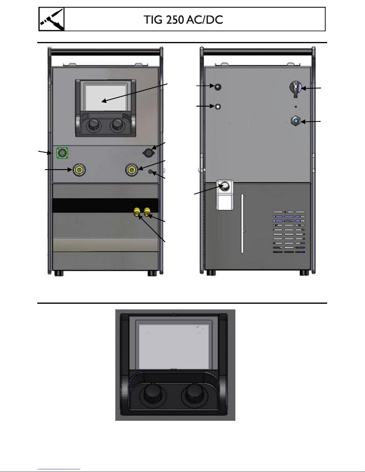
FIG-1
FIG-2
⑧ ①
② ③
④
⑤ ⑥
⑦
⑨
⑪
⑫
⑩
①
②
⑬

Safety instructions
Thank you for choosing this mac hine! To get the be st use from your machi ne please read the following carefully.
This User Manual is designed to help you get the most out of your welding equipment.
Read and understand the following safety recommendations before using or servicing the unit.
Any modification or maintenance not indicated in the manual must not be carried out.
The manuf act urer is not responsible for any injury to the operator or damage to the equipment or surrounding area,
due to failure to follow the instructions detailed in this manual.
If there is any issue or uncertainty, please consult a qualified individual to operate the equipment correctly.
Workplace
This equipmen t must only be used for we lding operat ions in accord ance with the limits ind icated on t he descrip tive
panel and/or in the user manual. The operator must respect the safety precautions that apply to this type of
welding. The manufacturer is not responsible for any incorrect or dangerous operation.
According to the standard IEC 60974-10, this class A device is designed to be used in an indus trial or professional
environment.
It can be difficult to ensure electromagnetic compatibility, due to conducted disturbances as well as radiation.
This equipment must be used a nd stored in a place protected from dust, acid o r any other corrosive. Operate the
machine in an open, or well-ventilated area.
Operating temperature:
Use between 10 and +40°C (+14 and +104° F).
Store between -25 and +55°C (-13 and 131°F).
Air humidity:
Lower or equal to 50% at 40°C (104°F).
Lower or equal to 90% at 20°C (68°F).
Up to 2,000m above the sea level (6500 feet).
Do not use this equipment to thaw pipes, to charge batteries, or to start any engine.
Individual protection
Arc welding can be dangerous and can cause serious and even fatal injuries.
Protect yourself and protect others.
Welding exposes the user to dangerous heat, arc rays, electromagnetic fields, noise, gas fumes, and electrical
shocks. People wearing pacemakers are advised to see their doctor before using this device.
In order to protect against burns and arc eye, protective clothing should be worn at all times: fire-proof clothing
(cotton, overalls or jeans), protective gloves and a fire-proof apron, ensuring whole body is covered.
Wear protective gloves which guarantee you an electrical and thermal insulation.
It may be necessary to install fireproof welding curtains to protect others against arc rays, weld spatters and sparks.
Inform the p eople aroun d the working area to not lo ok at the arc r ay or the mo lten metal and to wear prote ctive
clothes.
It is necessary to protect yourself with a welding hood (rated NR.10 or higher) and to protect your eyes during the
operation.
Do not operate whilst wearing contact lenses.
Ensure ear protection is worn by the operator and anyone in the surrounding area if the work exceeds the
authorised noise limit.
DO NOT TOUCH moving parts (e.g. engine, fan...) with hands, hair, clothes etc...
The rollers must not be touched when the wire feeder is working.
Never remove the safety cover of the wire feeder when the machine is plugged in - The manufacturer is not
responsible for any accident or injury that happens as a result of not following these safety precautions.

Do not point the torch towar ds any part of the body when the wire feeder is working - the wir e can cause injuries
when exiting the to r ch.
CAUTION: the workpiece can still be hot after welding has finished and can cause burns if handled.
The user mus t ensure that the torch has suffic iently cooled down before starting any cleaning operation. A cool-
down period of 10 minutes after e ach welding o peration is required. Whe n work ing with a wa ter coo led torch, make
sure that the water cooling system is on to avoid any burns caused by the liquid.
ALWAYS ensure the working area is left as safe and secure as possible to prevent damage or accidents.
Welding fumes and gas
The fumes, gases and dust pro duced during welding are hazardous. It is mandator y to ensure adequate ven tilation
and/or ex trac tion to keep fumes and gases away from the work area. An air f ed helmet is recomme nded in cases of
insufficient air supply in the workplace. Check that the air intake is in compliance with safety standards.
Care must be taken when welding in small areas, and the operator will need supervision from a safe distance.
Welding certain pieces of metal containing lead, cadmium, zinc, mercury or beryllium can be extremely toxic. The
user will also need to degrease the workpiece before w elding.
Gas cylinders must be stored in an open or ventilated are a. The cylinders must be in a vertical position sec ured to a
support or trolley.
Do not weld in areas where grease or paint are stored.
Fire and explosion risks
Protect the entire welding area.
Compressed gas containers and other inflammable material must be moved to a minimum safe distance of 11
meters.
Welding of sealed containers or closed pipes should not be undertaken, and if opened, the operator must remove
any inflammable or explosive materials (oil, p etrol, gas...). A fire extinguisher must be readily available.
Be careful - spatter and sparks can create fire or explosion.
Grinding work must not be carried out close to this welding equipment.
Gas cylinders
Gas leaking from the cylinder can create a hazard if present in high concentrations around the work area.
Always keep cylinders in an upright position securely chained to a fixed support or trolley.
Close the bottle after any welding operation. Be careful with gas bottles placed in areas of high temperature, or in
sunlight.
Cylinders should be located away from areas where they may be struck or subjected to physical damage. Always
keep gas bottles at a safe distance from arc welding or cutting operations, and any source of heat, sparks or flame.
Be careful whe n opening the valve on the gas bottle, it is necessary to remove the tip of the valve and make sure
the gas meets your welding requirements.
Electrical safety
The machine mus t be connected to an earthed electrical supply. Use the recommended size of fu se.
An electrical shock can cause severe injuries or even death directly or indirectly.
DO NOT TOUC H a ny L I V E p ar t o f t he m ac hi ne (i ns ide o r o uts id e ) w he n i t i s plugged in (T or ches, earth cable, cables,
electrodes) because they are conn ected to the welding circuit
ALWAYS unp lug the machine and wait for 2 minutes before opening the machine - this allows the capacitors to
discharge.
Never weld in rain or on a wet surface. The electrical cab les must never be in contact with liquid.
Do not touch the torch and earth cable at the same time.
Damaged cables and torches m ust be cha nged by a qualifie d and ski lled pr ofe ssional. Alw ays use the correct size o f
DIN connectors.
Always wear dry clothes in good condition to be insulated from the electrical circuit. Always wear insulated shoes in
any welding are a.
Magnetic fields and interferences
An electromagnetic field is created around the cables by current flow.
According to the standard IEC 60974-10, this class A device is designed to be used in an indus trial or professional
environment. It can be difficult to ensure electromagnetic compatibility, due to conducted disturbances as well as
radiation.
This equipment must be used and stored in a place protected from dust, acid, gas or any other corrosive substance.
Attention: this equip ment does not co mply with the s tandard IEC6100 0-3-12. If the machi ne is connected to the
public netwo rk on low vo ltage, the installer and opera tor must ens ure that t he machine can be co nnected - consult
your power supplier if necessary.
In order to reduce possible electromagnetic disturbances, you can:
Install electric filters close to the socket in case of excessive conducted disturbances. The earth and torch cables
should be as short as possible and be placed close together as far as possible from any other cable, power tool or
electrical cables.
The electromagnetic fields can disturb other equipment, eg; pacemaker or hearing aid.
People wearing pacemakers are advised to consult their doctor before using this device.
Do not use the welding unit to thaw pipes.
Handle gas cylinders with care. There is increased danger if the bottle or it's valve are damaged.
Electric and magnetic fields may interfere with netwok cables and may cause disturbances.
Never wrap the welding leads arou nd your body. Do not place your body between the earth and the torch cable,
they should be placed on the same side.
Electromagnetic disturbances should be reduced as much as possible if they disturb the operator's activity. The
operator is responsible for the installation and the use of the welding equipment and should seek advice from the
manufacturer if required.
Electric wiring rule to reduce disturbances
It is sometimes useful to set all the parts at the same voltage (while respecting the standards in place for each) .
Installing an earth connection to the workpiece may reduce the disturbances, and will not increase the risk to the
operator or any other electrical appliances.
The shielding of the welding cables and of any other cables may be useful.
IP protection
IP23S
- Protection prevents access to hazardous parts with fingers or other solid foreign bodies with a diameter equal to or
higher than 12.5mm
- Protective grid - against rain fall at an angle of 60°.
- Case protects against effects of water/dust penetration when the equipment is not in use.
Set up
Only qualified personnel authorized by the manufacturer should perform the installation of the welding equipment.
During set up, the operator must ensure that the machine is unplugged. The serial or parallel connections on a
generator are prohibited.
Transportation of the machine
Two handles are fitted on the equipm ent to carry it easily, be careful to not underestimate its weight.
This machi ne is not equipp ed with a li fting fascil ity - the operator is required to make the necessary arrangements
for safe lifting and transport of the machine (be careful not to tilt the machine).
Do not use the cables or torch to move the machine. The welding equipment must be moved in an upright position.
Never lift the machine while there is a gas cylinder on the support shelf - follow the separate movement guidelines
specified for the gas bottle.
The removal of the wire reel from the mac hine is recommended before undertaking any lifting operation.
Setting up the machine
Rules to follow:
¤ Put the machine on the floor (maximum incline of 15°.)
¤ Ensure the work area has sufficient ventillation for welding, and that there is easy access to the control panel.
¤ The machine must be placed in a sheltered area away from rain or direct sunlight.

DESCRIPTION
Thank you for choosing this machine! To get the best use from your machine please read the following carefully.
The TIG 250 AC/DC is a portable, single phase, ventilated Inverter welding unit to be used with non consumable
electrode (TIG) in direct (DC) or alternative (AC) current. TIG welding requires a gas shield protection of
pure(Argon). In MMA mode, it allows you to weld with any kind of electrodes: rutile, basic, stainless steel or cast
iron.
The TIG 250 AC/DC can be equipped with a remote control or foot pedal.
The TIG 250 AC/DC has an integrated liquid cooling system to connect liquid cooled torches.
POWER SUPPLY – STARTING UP
• This machine is delivered with a 5 pin three-phase plug (3P + N + PE) 400V 16A type CEE17. The TIG 250 AC/DC
must be co nnected to a 400 V socket (50 - 60 Hz) WITH ear th protecte d by a 16A circ uit breaker and a 30mA
overcurrent discontactor. The absorbed current (I1eff) is indicated on the device, for its maximum setting.
Check that the power supply and its protection (fuse and/or circuit breaker) are compatible with the
current needed by the machine. In some countries, it may be necessary to change the plug to allow the
use at maximum settings.
This unit has an internal cooling liquid system which has 2 main functions: the cooling of the water torch if
connecte d and the cooling o f internal sp are parts. So the tank of the unit n eeds to be filled to the maximum line
indicated at the back of the machine.
•
The starting up is made by pushing on the standby button.
•
The device turns into protection mode if the power supply tension is under 360V or over 440V or if a
phase is missing. To indicate this default, the screen displays. Once in protection mode, you have to
unplug the device and plug it back into a socket delivering the correct voltage (see the table of error
messages).
• Fan: in MMA mode, the fan works no nstop. In TIG mode, the fan works only w hen welding, then stops after
cooling.
•
These are Class A devices. They are designed to be used in an industrial or professional environment. In a
different environment, it can be difficult to ensure electromagnetic compatibility due to conducted
disturbances as well as radiation
. They comply with the norm CEI 61000-3-12.
DEVICE PRESENTATION (FIG-1)
① Screen + potentiometers
② + polarity plug
③ - polarity plug
④ Gas connection for torch
⑤ Trigger connection
⑥ Water input for water cooled torch
⑦ Water output for water cooled torch
⑧ Remote control connection
⑨ 5A fuse support
⑩ ON / OFF switch
⑪ Power cable
⑫ Tank
⑬ Gas inlet
CONTROL BOARD (IHM) (FIG-2)
The control board is made of a c olour TFT screen and two potentiometers. How it works in 3 states:
State 1 or Standby mode: with the potentiometer 1 you will be able to set the welding current, and with the
potentiometer 2 the parameters related to the welding current.
State 2 or Welding mode: by push ing the potentio m e te r 1 you will have ac c e s s to the to p m e nu. The n b y t ur n ing the
button you wil l sele ct the weld ing mo de . You will exit th is me nu by w aitin g 8s or by pushing the potentiometer 2 ->
back to State 1.
State 3 or Welding parameters mode: by pushing the potentiometer 2 you will have access to the welding
parameters and you will see the selection by turning the button. You will exi t this me nu by wai ting 8s o r by pus hing
the potentiometer 2 -> back to State 1.
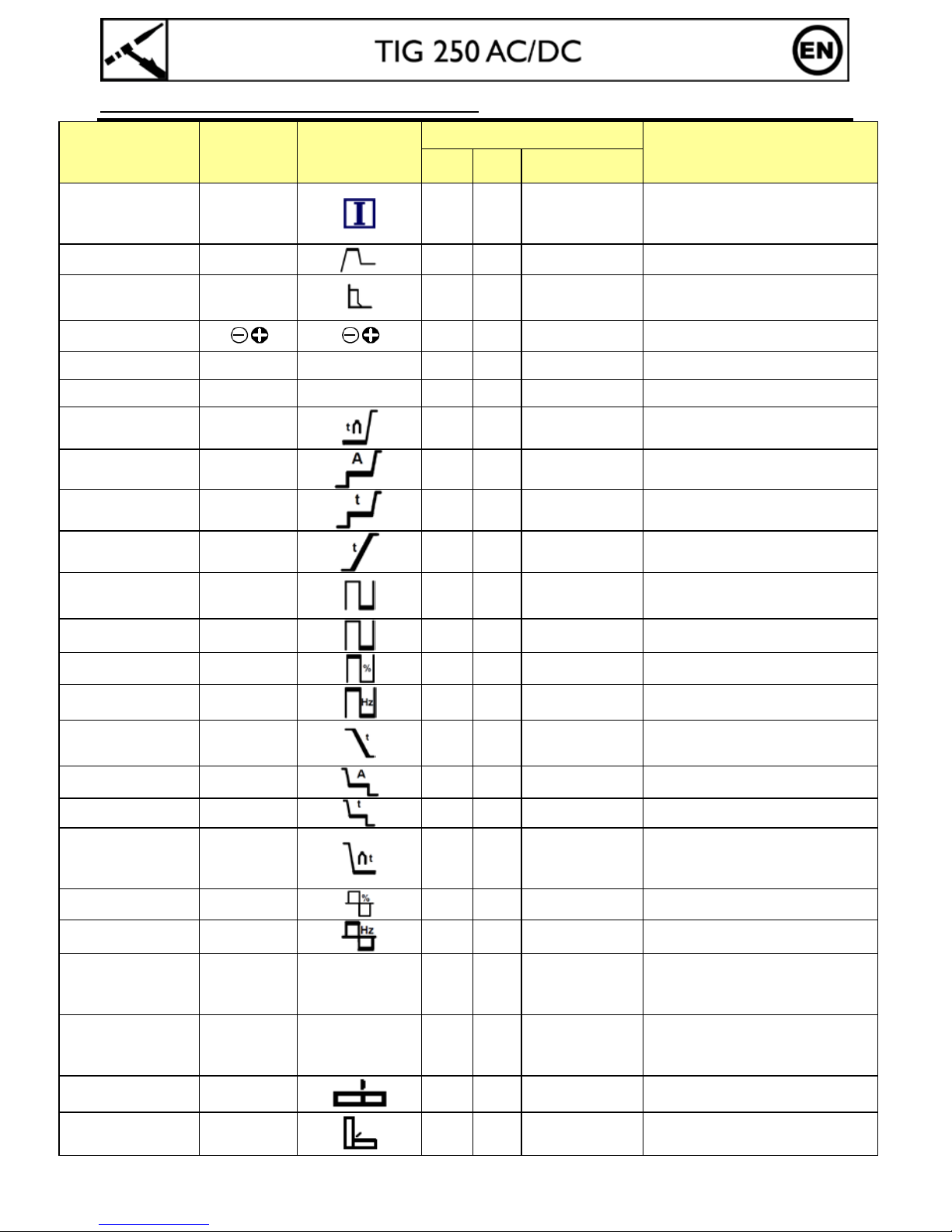
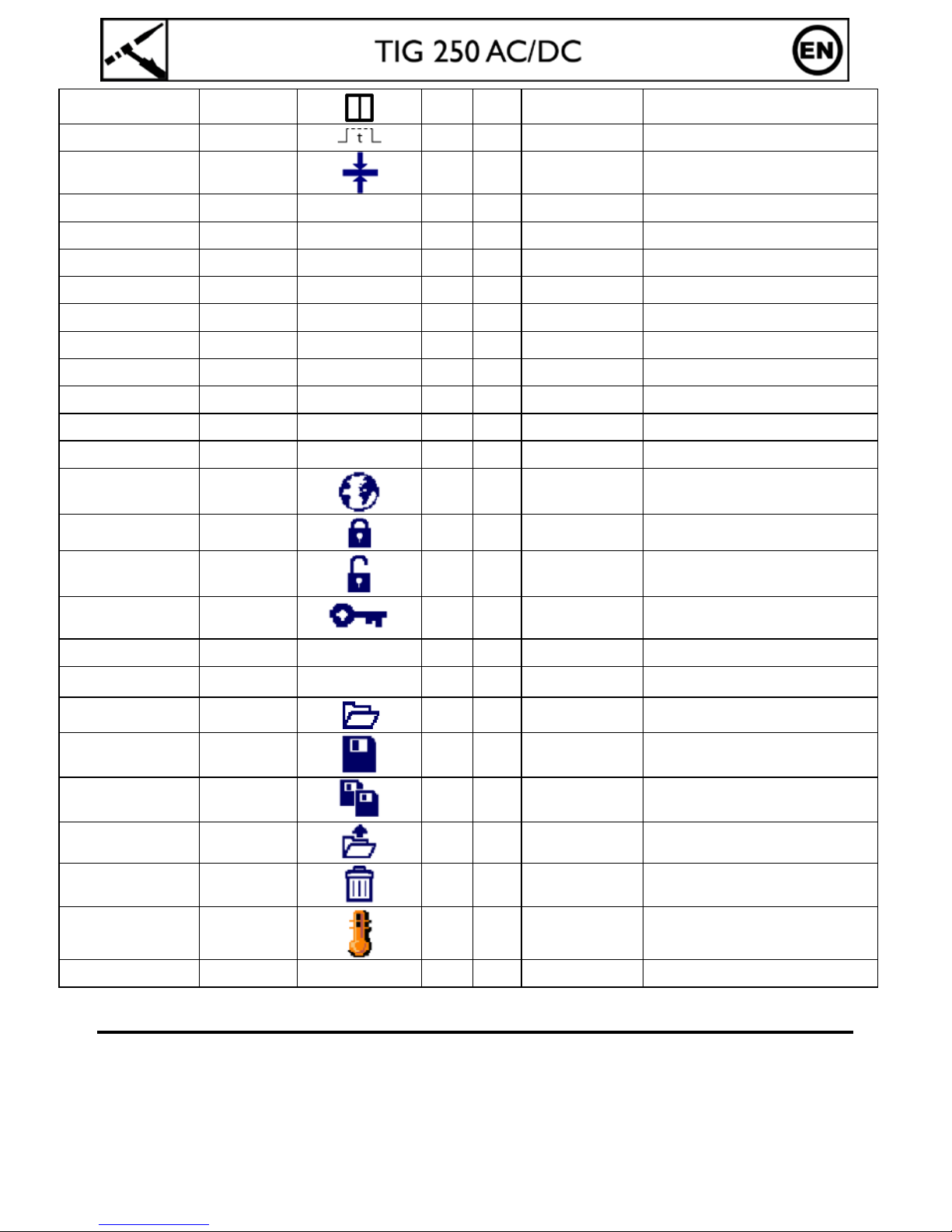
FUNCTION, MENU AND PICTOGRAM DESCRIPTIONS
FUNCTIONS Description Pictogram
Function a vai l ab l e on
Comment
TIG
DC
TIG
AC
MMA
Welding current Current
X
Value of the welding cu r ren t needed
depends on the thick n ess an d the type
of metal, as well as on the w eld in g
joint. (A)
HotStart HotStart
X
Adjustable overcurrent at the beginning
of the welding (%)
ArcForce ArcForce
X
Overcurrent delivered to avoid sticking
when the electrode enters t h e weld in g
pool (%)
Polarity reversal
X
Easy reversal of the polarity in order to
weld with different t y pe of electrodes
HF arcing HF - X X Ignition without contact
LIFT arcing LIFT
-
X X Ignition with contact
Pre-Gas Pre-Gas
X X
Time to purge the torch and to protect
the area with gas befor e ignition
Starting current I Start
X X Pre current (A)
Starting time T Start
X X Pre current time (S)
Up slope UpSlope
X X
Time needed to go from minimum
current to welding current (S)
Cold current (4TLog) I Cold
X X
Background welding current or cold
current activated with a double button
torch or in 4T LOG (A)
PULSE cold current I Cold
X X
Base current or cold current in PULSE
mode (A)
PULSE balance %T Pulse
X X Cold current balance (%)
PULSE frequency Hz Pulse
X X Pulse frequency (Hz)
Down slope DownSlope
X X
Time needed to shift fr o m w elding
current to minimum current, I Stop (S)
to avoid weld defect s and craters.
Ending current
I Stop
X X Post Welding current (A)
Ending time T Stop
X X Post Welding time (S)
Post Gas Post Gas
X X
Length of time in which g as is r eleased
after the arc has stopped. It protects
the weld pool and th e electrode against
oxidization when the metal is cooling.
AC balance %T AC
X
Wave balance control of penetration
and cleaning (%)
AC frequency Hz AC
X Welding frequency in AC (Hz)
Electrode diameter Ø X X
Diameter of the electrode tungsten
recommended to optimize the arcin g
and the welding of certain thickness of
metal in SYNERGIC mode
Metal to weld
Fe, CrNi,
Cu/CuZn,
AlMg, AlSi,
Al99
X X
Selction of th e m etal to weld: Steel,
Nickel-Chromium, Cusi or brass,
Aluminium-Magnesium, Aluminium-
Silicon in SYNERGIC mode
Butt weld
X X SYNERGIC mode
Fillet weld
X X SYNERGIC mode
Vertical Down weld
X X SYNERGIC mode
Spot delay
X X Spoting time
Thickness of the metal
to be welded
X X
Material thick n ess g uide in SYNERGIC
mode
MMA process MMA X
TIG AC process AC X
TIG DC process DC X
SYNERGIC mode SYNERGIC X X
Standard mode STD X X
Pulse mode PULSE X X
Spot mode SPOT X X
2T 2T X X 2 Tim e t o rc h m ode
4T 4T X X 4 Time torch mode
4T LOG 4T LOG X X 4 Time LOG torch mod e
Languages
X X X Selection of the language
Control board locking
X X X
Locking the control board to stop
accessing to menu s an d param et er s
Control board
unlocking
X X X
Unlocking the control board to open
back the access to menus and
parameters (default code: 0000)
Password mod if ic ation
X X X Allow the modification of the password
Reset parameters RESET X X X Allow to restore the original parameters
Identification ID X X X
After Sales module to id en t if y t h e
machine
Backup menu
X X X
Menu where old welding par am et er s
are saved
Save
X X X
Save the welding parameters under the
name given
Save as
X X X
Save the welding par am et er s with a
new name
Open
X X X
Open a welding configuration saved
previously
Delete
X X X
Delete a welding configuration saved
previously
Thermal protection
X X X
Symbol indicating the state of the
thermal protection
Connect-5 X X Automate mode
MMA WELDING (ELECTRODE)
Getting Started
• Connect the electrode holder and earth clamp to the corresponding sockets.
• Ensure that the welding polarities and intensities indicated on the electrode packaging are observed.
• Remove the electrode from the electrode holder when the machine is not in use.
 Loading...