

GYS M1 GYS AUTO 208/240V (USA), M1 GYS AUTO, T1 GYS AUTO DV, T1 GYS AUTO, M3 GYS AUTO 208/240 (USA) User guide [ml]
...Page 1
FR 6-10 / 27-44
M1 GYS AUTO 208/240V (USA)
M1 GYS AUTO
EN 11-15 / 27-44
DE 16-20/ 27-44
ES 21-25 / 27-44
RU 28-30 / 27-44
75560 - V7 - 6/07/2015
T1 GYS AUTO DV
T1 GYS AUTO
M3 GYS AUTO 208/240 (USA)
M3 GYS AUTO
T3 GYS AUTO DV
T3 GYS AUTO
www.gys.fr
Page 2
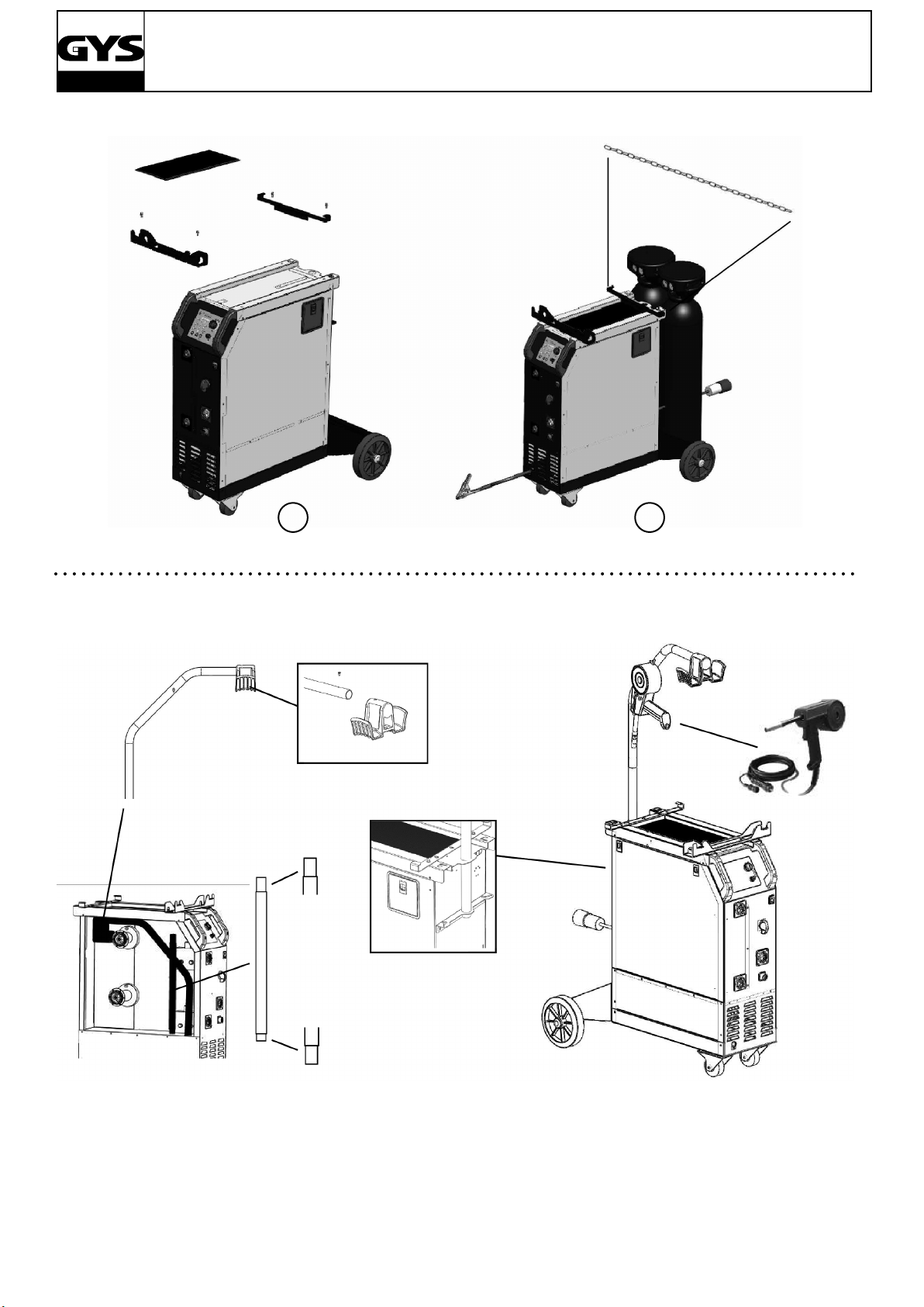
I - M1 & T1
M1 - T1 & M3 - T3 GYS AUTO
II - M3 - T3
10
12
13
7
11
9
6
3
2
1
5
4
8
10
Fig 2-B :
12
15
Fig 2-C :
16
13
15
7
11
9
6
3
5
1
4
2
4
8
III
A
B
2
Page 3
IV
M1 - T1 & M3 - T3 GYS AUTO
5
6
2
1
3
V
4
6
4
2
5
VI
3
1
3
Page 4
VII
M1 - T1 & M3 - T3 GYS AUTO
1
M3 - T3 GYS AUTO
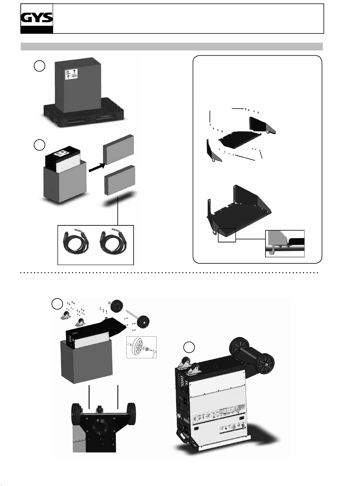
• Prémonter les vis manuellement
sans les bloquer
• Pre-install the screws manually
without blocking them
Vis/Screws
M5x12 (x8)
2
Ecrous/Nuts
M5x8 (x8)
M1 - T1 - T3 - M3 GYS AUTO
3
Visser toutes les vis du support bouteilles
Tighten all the screws of the gas bottle stand
4
4
Page 5
M5x12 (x4)
M1 - T1 & M3 - T3 GYS AUTO
5 6
M3 - T3 GYS AUTO (option ref. 032880 / 038897 / 032958 / 032972 )
5
Page 6

M1 - T1 & M3 - T3 GYS AUTO
DESCRIPTION
Merci de votre choix ! An de tirer le maximum de satisfaction de votre poste, veuillez lire avec attention ce qui suit :
Les M1 GYS auto, T1 GYS auto, M3 GYS auto et T3GYS auto sont des postes de soudure semi-automatique « synergic »
sur roues, ventilés pour le soudage (MIG ou MAG). Ils sont recommandés pour le soudage des aciers, des inox, des aluminiums et pour le soudo brasage des aciers haute résistance avec les ls CuSi et CuAl (idéal en réparation carrosserie).
Leur réglage est simple et rapide grâce à la fonction « vitesse de l synergique ». Les T1 et T3 GYS auto fonctionnent
sur une alimentation 400V triphasée ou en 230V/400 V triphasée pour le T1 GYS auto DV et T3 GYS auto DV. Le M1 et
M3 GYS auto fonctionnent en 230V monophasées ou en 208/240V pour le M1 208/240V et M3 208/240V.
ALIMENTATION ÉLECTRIQUE
Le courant effectif absorbé (I1eff) pour les conditions d’utilisation maximales est indiqué sur l’appareil. Vérier que
l’alimentation et ses protections (fusible et/ou disjoncteur) sont compatibles avec le courant nécessaire en utilisation.
L’appareil doit être placé de façon telle que la che de prise de courant soit accessible.
- Ces appareils sont livrés avec une prise 16A de type Rs-015 CEE.
- Les M1 et M3 GYS AUTO doivent être reliés à une prise 230V 1PH AVEC terre protégée par un disjoncteur 16A retardé
et différentiel 30mA.
- Les T1 GYS auto, T3 GYS auto, T1 GYS auto DV et T3 GYS auto DV doivent être relié à une prise 400V 3ph AVEC terre
protégée par un disjoncteur 16A retardé et différentiel 30mA. Ne pas utiliser de rallonge ayant une section inférieure à
2,5 mm².
FR
- Pour les T1 GYS auto DV et T3 GYS auto DV seulement : Alimentation 230V triphasée, ATTENTION : cet appareil est
pré-monté en usine en 400V triphasée. Si votre installation électrique est en 230V triphasé, veuillez modier le branchement de la plaque de bornes à l’intérieur du poste. Cette manipulation doit être effectuée par une personne compétente.
Pour ce faire se référer au schéma de branchement 230V situé à l’intérieur du poste. L’alimentation électrique doit être
protégée par un disjoncteur 16A et un différentiel 30mA. (Voir schéma électrique en n de manuel)
- Pour les M1 GYS auto 208/240V et M3 GYS auto 208/240V : Alimentation 208V monophasée, ATTENTION : cet appareil
est pré-monté en usine en 240V monophasée. Si votre installation électrique est en 208V monophasée, veuillez modier
le branchement de la plaque de bornes à l’intérieur du poste. Cette manipulation doit être effectuée par une personne
compétente. Pour ce faire se référer au schéma de branchement 208V situé à l’intérieur du poste. L’alimentation électrique doit être protégée par un disjoncteur 16A et un différentiel 30mA. (Voir schéma électrique en n de manuel)
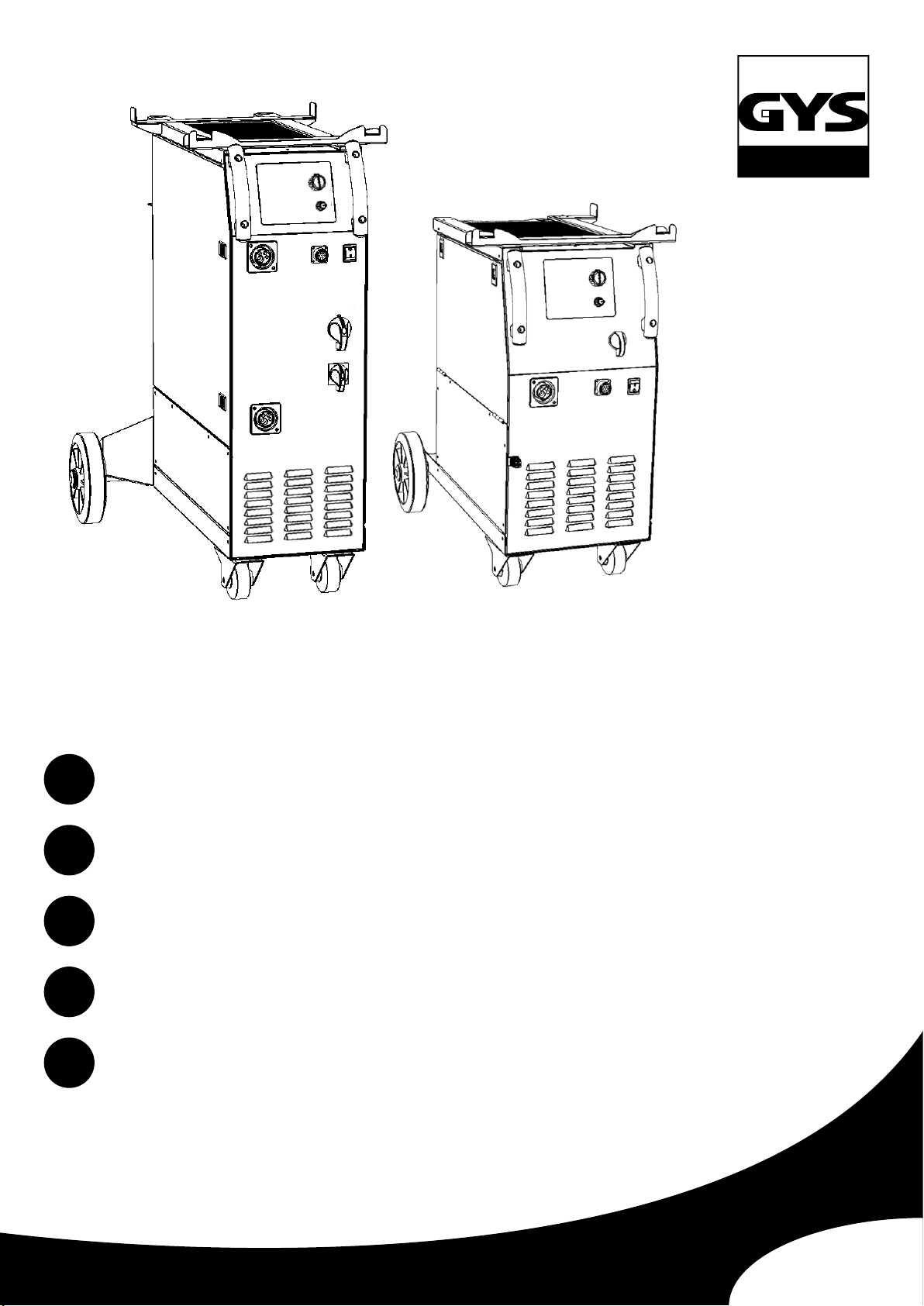
DESCRIPTION DU POSTE (FIG 1 & 2)
1- Interrupteur marche arrêt
2- Réglage de puissance par un commutateur 7 positions
suivant le poste : permet d’ajuster la tension de soudage
en sortie de générateur. Le réglage de tension de sortie
est proportionnel à l’épaisseur du matériau à souder.
(g. 6)
3- Clavier de réglages des paramètres de soudage (mode
manuel ou automatique).
9- Support bouteilles (maxi 1 bouteille 4m³ pour le
M1GYS AUTO et maxi 2 bouteilles de 4m³ pour les
T1GYS, T3GYS, M3GYS).
10- Chaine de xation pour bouteille. Attention : bien
xer la bouteille !
11- Support bobine Ø 200/300 mm.
12- Electrovanne torche 1.
4- Raccords torche au standard européen.
5- Connecteur de commande du spool gun.
6- Support torches avant.
7- Câble d’alimentation (2m M1GYS AUTO, 3m T1GYS,
6m T3GYS et M3 GYS).
8- Sortie pince de masse pour les T1GYS et M1GYS
AUTO, câble de masse avec pince 200A pour le T3GYS et
M3GYS.
13- Support de câble torche arrière.
Pour les T3GYS :
14- Support bobine Ø 200mm.
15- Electrovanne torche 2.
16- Electrovanne torche spool gun
6
Page 7

M1 - T1 & M3 - T3 GYS AUTO
SOUDAGE SEMI-AUTOMATIQUE EN ACIER/INOX (MODE MAG) (FIG 3)
Ces appareils peuvent souder du l acier et inox de 0,6/0,8 et 1. (g 3A) L’appareil est livré d’origine pour fonctionner
avec du l Ø 0,8 mm en acier. Lorsque vous utilisez du l de diamètre 0,6 mm ; il convient de changer le tube contact.
Le galet du moto-dévidoir est un galet réversible 0,6 / 0,8mm. Dans ce cas, le positionner de telle façon à lire 0,6 mm
sur le anc visible du galet. L’utilisation en acier ou inox nécessite un gaz spécique au soudage argon + CO2 (Ar +
CO2 ).La proportion de CO2 varie selon l’utilisation. Pour le choix du gaz, demander conseil à un distributeur de gaz. Le
débit de gaz en acier se situe entre 8 et 12 L/min selon l’environnement et l’expérience du soudeur.
SOUDAGE SEMI-AUTOMATIQUE ALUMINIUM (FIG 3)
Ces appareils peuvent souder du l aluminium de 0,8 et 1 mm. (g 3B).
Pour souder l’aluminium, il faut utiliser un gaz neutre: argon pur (Ar). Pour le choix du gaz, demander conseil à un
distributeur de gaz. Le débit du gaz se situe entre 15 et 25 L/min selon l’environnement et l’expérience du soudeur. Cidessous les différences entre l’utilisation soudage acier et soudage aluminium :
- La pression des galets presseurs du moto-dévidoir sur le l : mettre un minimum de pression an de ne pas écraser
le l.
- Tube capillaire : retirer le tube capillaire avant de connecter la torche aluminium avec une gaine en téon.
- Torche : utiliser une torche spéciale aluminium. Cette torche possède une gaine téon an de réduire les frottements.
- NE PAS couper la Gaine au bord du raccord !! cette gaine sert à guider le l à partir des galets. (gure 3-B)
- Tube contact : utiliser un tube contact SPECIAL aluminium correspondant au diamètre du l.
FR
SOUDAGE SEMI-AUTOMATIQUE DES ACIERS À HAUTE LIMITE ÉLASTIQUE
Ces appareils sont recommandés par les fabricants d’automobiles pour soudobraser les tôles à haute limite élastique
avec un l en cuprosilicium CusI3 ou cuproaluminium CuAl8 (Ø 0,8mm et Ø 1mm). Le soudeur doit utiliser un gaz
neutre: argon pur (Ar). Pour le choix du gaz, demander conseil à un distributeur de gaz. Le débit du gaz se situe entre
15 et 25 L/min.
RACCORDEMENT GAZ (FIG 2)
Visser le mano-détendeur sur la bouteille de gaz (le manodétenteur n’est pas livré avec le poste).
Pour une utilisation avec une ou deux bouteilles de gaz.
Pour relier 2 bouteilles de gaz aux 3 torches, il faut couper le tuyau en 3 et connecter 1 Y. (g 2C)
Pour relier une seule bouteille de gaz aux 3 torches, il faut couper le tuyau en 4 et connecter 2 Y. Connecter chaque
bouteille sur les électrovannes en respectant l’ordre :
- électrovanne T1 en haut à gauche (g 2B:13)
- électrovanne Spool gun en haut à droite (g 2B:17)
- électrovanne T3 en bas. (g 2B:16) Pour éviter toute fuite de gaz, utiliser les colliers livrés avec l’appareil.
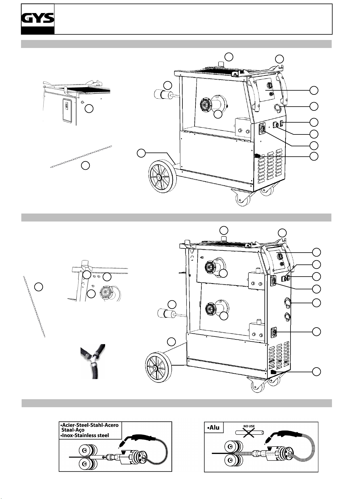
PROCÉDURE DE MONTAGE DES BOBINES ET DES TORCHES (FIG 4)
- Ouvrir la trappe du poste.
- Positionner la bobine en tenant compte de l’ergot d’entrainement (g 4:2) du support bobine.
- Régler le frein de la bobine (g 4:3) pour éviter lors de l’arrêt de la soudure que l’inertie de la bobine n’emmêle le l.
De manière générale, ne pas serrer trop fort !
- Les galets moteur (g 4:4) sont des galets double gorge (0,6/ 0,8 et 0,8/ 1). L’indication qu’on lit sur le galet est celle
que l’on utilise. Pour un l 0,8 mm, utiliser la gorge de 0,8.
- Pour la première mise en service :
- Desserrer la vis de xation du guide l (g 4:6)
- Pour régler la molette des galets presseurs (g 4:5), procéder comme suit :
- Desserrer au maximum, actionner le moteur en appuyant sur la gâchette de la torche, serrer la molette tout en restant appuyé sur la gâchette. Plier le l en sortie de la buse. Mettre un doigt sur le l plié pour l’empêcher d’avancer. Le
réglage du serrage est bon lorsque les galets patinent sur le l même si le l est bloqué en bout de torche.
- Choisir le diamètre du tube contact au bout de la torche. Utiliser un tube contact adapté au diamètre du l utilisé.
Le réglage courant: la molette des galets (g 4:5) sur graduation 3 pour l’acier et 2 pour l’aluminium.Nb: pour le l
aluminium mettre un minimum de pression an de ne pas écraser le l.
7
Page 8
M1 - T1 & M3 - T3 GYS AUTO
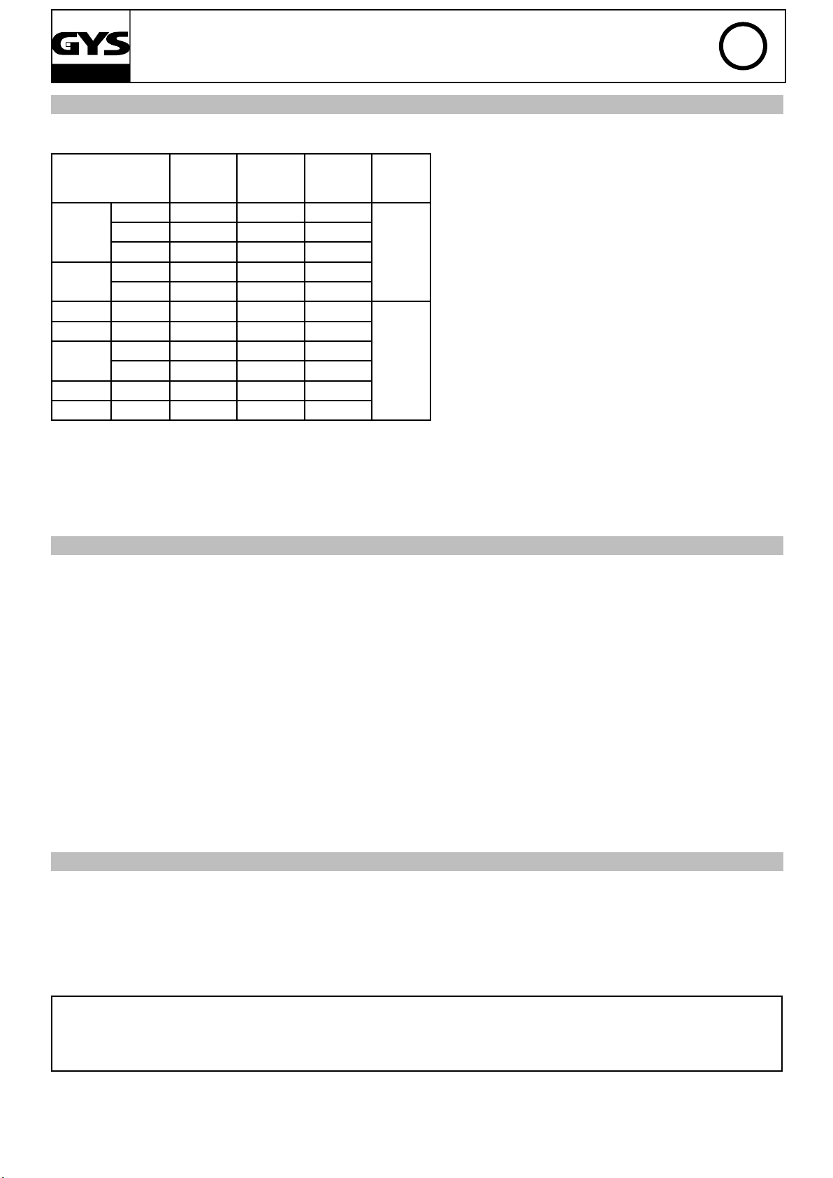
CHOIX DES BOBINES
Congurations possibles:
type l
Ø 300 x
acier
inox
CuSi3 Ø 200 x x
CuAl8 Ø 200 x x
Alu
AlMg5
AlSi5 Ø 100 x
AlSi12 Ø 100 x
Ø 200 x x
Ø 100 x
Ø 200 x x
Ø 100 x
Ø 300 x*
Ø 200 x* x*
Torche 1
T1,T3,M1,M3
Torche 2
T3/M3
Spool gun
T1/T3/M1/M3
CuSi3:préconisation OPEL et Mercedes
CuAl8:préconisation Peugeot/Citroën/Renault
AlSi12:préconisation pour l’aluminium automobile à partir de tôle d’épaisseur comprise entre 0,6 et 1,5 mm
Gaz
argon
+
CO2
argon
pur
FR
*prévoir gaine téon/tube contact spécial alu
Ôter le tube capilaire
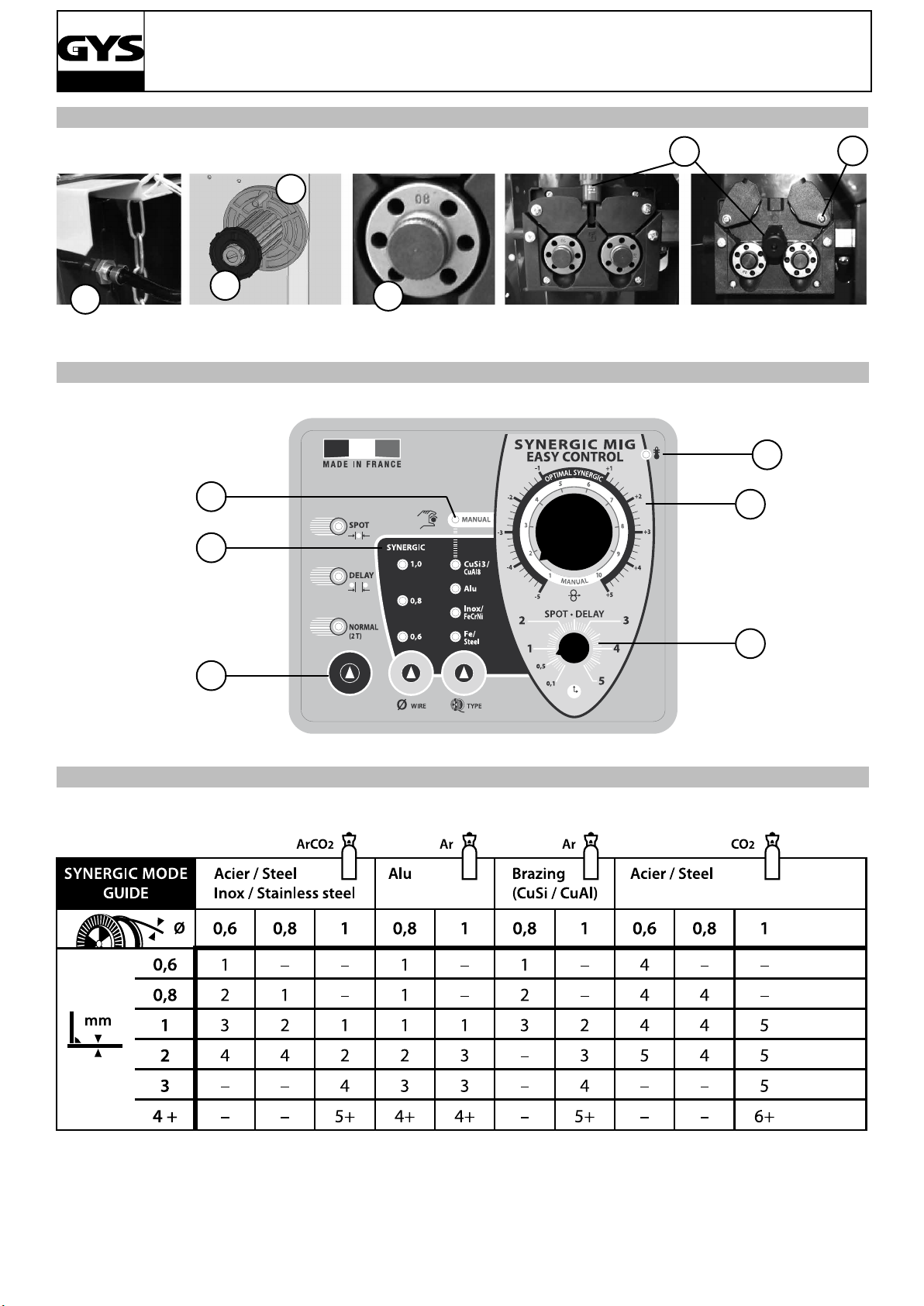
CLAVIER DE COMMANDE (FIG 5)
1- Choix du mode de soudage:
-NORMAL(2T) : soudage standard 2 temps
-DELAY : fonction «point de chainette», avec réglage du
diamètre de l’intermittence de point
-SPOT : fonction bouchonnage/spot, avec réglage du
diamètre du point.
5- Mode Synergic :
Positionner le potentiomètre (2) au milieu de la zone
«OPTIMALE SYNERGIQUE».
Dans ce mode le poste détermine la vitesse de l optimale à partir de 3 paramètres :
-Tension
2- Réglage de la vitesse :
Potentiomètre d’ajustage de la vitesse du l. La vitesse
varie de 1 à 15m/minute.
-Diamètre de l
-Nature du l Il est possible d’ajuster la vitesse du l +/-
En position Normal (2T), 2 modes sont proposés pour
faciliter le réglage du poste: Manual ou Synergic.
3- Potentiomètre de réglage SPOT/DELAY.
6- Voyant de protection thermique sur le clavier de com4- Mode Manual :
En mode manuel, la vitesse de dévidage du l est déterminée par l’utilisateur en ajustant le potentiomètre (2).
mande : signale une coupure thermique lorsque l’appa-
reil est utilisé de façon intensive (coupure de plusieurs
minutes).
MODE "MANUAL" (FIG 5)
Pour régler votre poste procéder comme suit:
-Choisissez la tension de soudage à l’aide du commutateur 7 positions
exemple: position 1 pour de la tôle de 0,6 mm et position 7 pour de la tôle de 4 mm
-Ajustez la vitesse du l à l’aide du potentiomètre (2)
conseil:
L’ajustement de la vitesse du l se fait souvent «au bruit»: l’arc doit être stable et avoir très peu de crépitement.
Si la vitesse est trop faible, l’arc n’est pas continu.
Si la vitesse est trop élevée, l’arc crépite et le l a tendance à repousser la torche.
8
Page 9
M1 - T1 & M3 - T3 GYS AUTO
MODE "SYNERGIC" (FIG 5)
Grâce à cette fonction, plus besoin de régler la vitesse du l.
Pour cela:
- Positionner le potentiomètre (2) vitesse de l au milieu de la zone «Optimal Synergic»
- Sélectionner:
- La nature du l (5)
- Le diamètre du l (5)
- La puissance (commutateur 7 positions en face avant) Pour sélectionner la position adéquate en fonction de l’épaisseur à souder se référer au tableau (g-6)
A partir de cette combinaison de paramètres, l’appareil détermine la vitesse de l optimale et le poste est prêt à souder.
Il est ensuite possible d’ajuster la vitesse du l si nécessaire + ou - grâce au potentiomètre (2).
Pour chaque torche , mémorisation des dernières congurations de soudage est effectuée (diamètre du l, nature du
l, mode).
Choix du GAZ(uniquement pour le soudage acier):
En mode synergique, le poste détermine les paramètres de soudage en fonction du gaz utilisé. Par défaut, en soudage acier, le poste est conguré «argon+CO2».
Pour changer de gaz et congurer le poste en mode CO2 ou revenir en mode Argon+CO2, procéder comme suit:
1-appuyer sur le bouton «Type» pendant 5 secondes jusqu’à ce que le clavier s’éteigne puis relacher le bouton.
2-Dans un délai de 5 secondes choisir la conguration souhaitée avec le bouton:"choix mode".
-Normal (2T)=>Argon+CO2(réglage par défaut)
-Delay=>CO2 100%
3-La validation se fait soit par la touche "Type" soit en attendant un délai de 5 secondes.
4-Une fois validé, le poste revient en mode fonctionnnement normal et la modication reste enregistrée même une
fois le poste éteint.
FR
MODE SPOT (FIG 5)
Cette fonction permet de réaliser des travaux de pointage. Pour ajuster la durée du point, utiliser le potentiomètre (3).
MODE DELAY (FIG 5)
Pour effectuer vos travaux en «points de chaînette», ajuster le potentiomètre (3). Cette fonction permet de souder
des tôles très nes en acier ou en aluminium, en limitant le risque de perçage et de déformation de la tôle (surtout
pour le soudage aluminium).
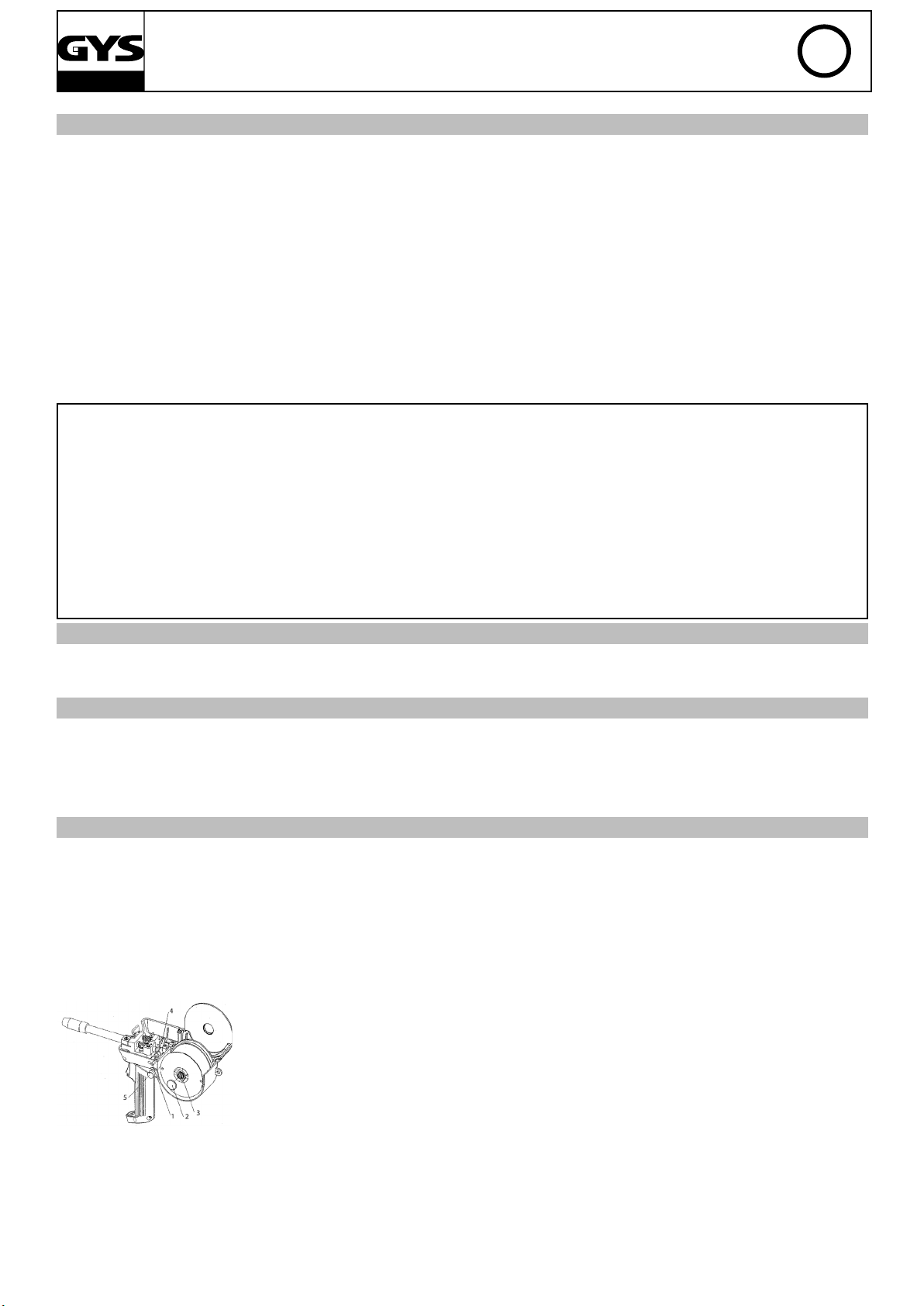
SPOOL GUN (OPTION)
Présentation et fonctionnement torche spool gun
- La torche spool gun se monte sur le connecteur de la torche.
- Le spool gun fonctionne soit en mode Manual ou en mode Synergic.
- En mode manuel ou synergique, seul le bouton de réglage de vitesse du l déporté sur la torche est actif (le potentiomètre vitesse de l est inactif).
- Mode Synergic:
- Placer le bouton vitesse du l de la torche au centre de sa plage puis ajuster si nécessaire.
1- Bouton d’ouverture/fermeture capot
2- Ecrou de serrage bobine
3- Ecrou de frein bobine(ne pas trop serrer)
4- Vis de réglage de tension des galets
5- Bouton de réglage de vitesse du l
9
Page 10
M1 - T1 & M3 - T3 GYS AUTO
Procédure de montage
Bobine:
- Ouvrir le capot-Enlever l’écrou de maintien (nb: pas de vis inversé)
- Serrer l’écrou frein an de bomber l’axe bobine (ne pas trop serrer)
- Insérer votre bobine
- Pour insérer le l dans les galets appliquer une pression sur la «vis de réglage tension galets».
- Retirer le l de la torche en enroulant la bobine.
- Retirer la torche.
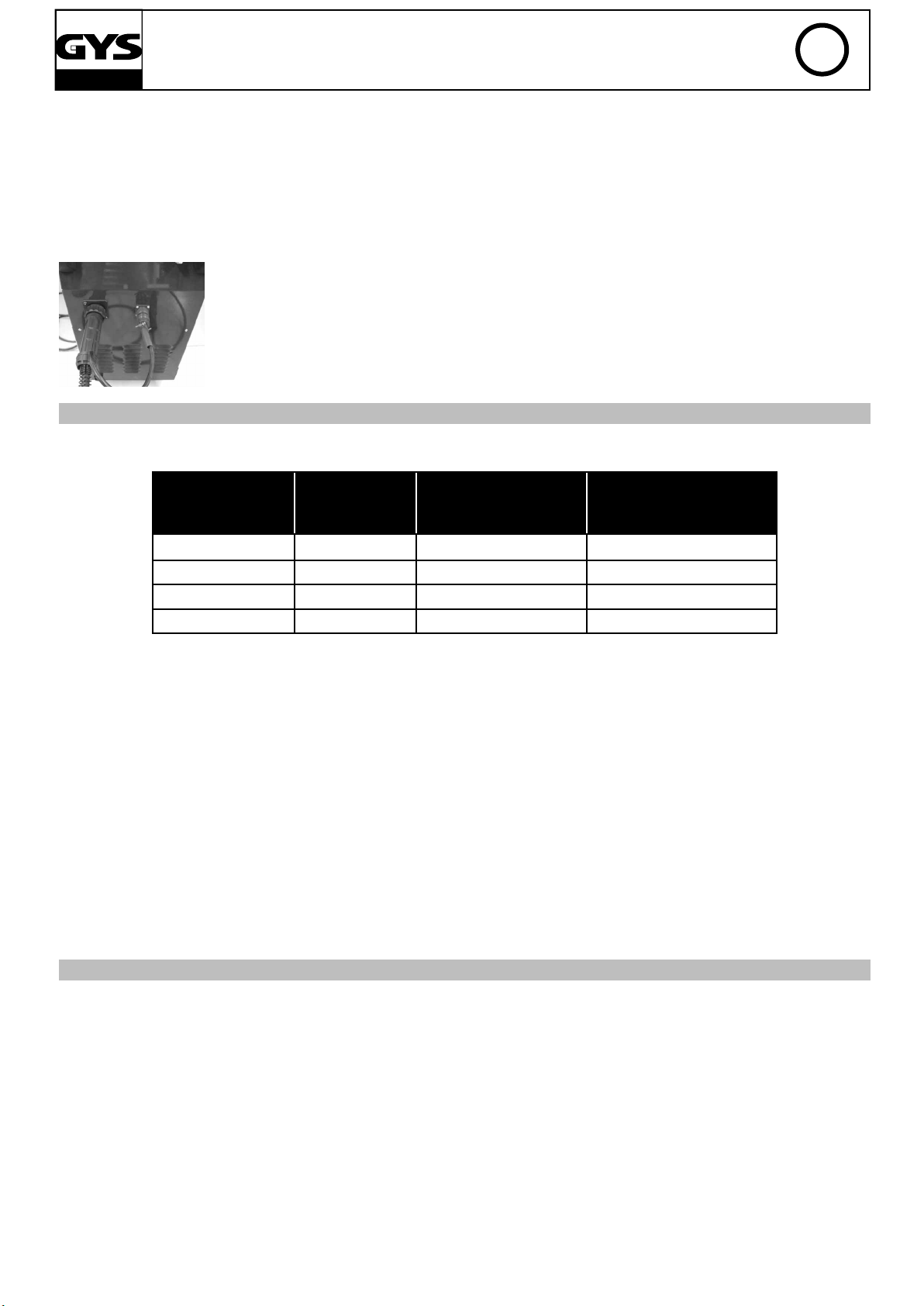
- Brancher le connecteur de puissance du spool gun sur le connecteur de la torche 1.
- Brancher le connecteur de commande du spool gun.
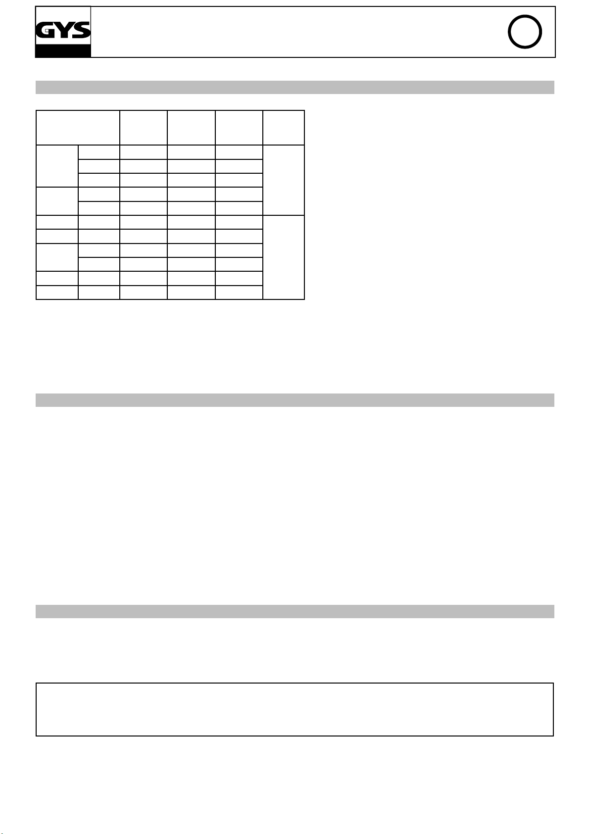
FACTEURS DE MARCHE ET ENVIRONNEMENT D'UTILISATION
- Le poste décrit a une caractéristique de sortie de type "tension constante". Son facteur de marche selon la norme
EN60974-1 est indiqué dans le tableau suivant:
X/60974-
1 à 40°C(T
cycle=10min)
T1 GYS AUTO 25% à 150A 110A 90A
I max 60%(T cycle=10min) 100%(T cycle=10min)
FR
T3 GYS AUTO 25% à 150A 110A 90A
M1 GYS AUTO 15% à 140A 80A 60A
M3 GYS AUTO 15% à 140A 80A 60A
Note: Les essais d’échauffement ont été effectués à température ambiante et le facteur de marche à 40°C a été déterminé par simulation.
- Ces appareils sont de classe A. Ils sont conçus pour un emploi dans une environnment industriel ou professionnel.
Dans un environnement différent, il peut être difcile d’assurer la compatibilité électromagnétique, à cause de perturbations conduites aussi bien que rayonnées. Ne pas utiliser dans un environnement comportant des poussières métalliques
conductrices.
- Les M1, M3, T1 et T3 sont conforme à la CEI 61000-3-12, à condition que la puissance de court-circuit Ssc soit supérieur ou égale à 1,8MVA au point d’interférence entre l’alimentation de l’utilisateur et le réseau public de distribution. Il
est de la responsabilité de l’installateur ou de l’utilisateur du matériel de s’assurer, si nécessaire en consultant l’exploitant
du réseau de distribution, que le matériel est raccordé uniquement à l’alimentation telle que la puissance du court-circuit
Ssc soit supérieur ou égale 1,8MVA.
CONSEIL ET PROTECTION THERMIQUE
- Respecter les règles classiques du soudage.
- Laisser les ouïes de l’appareil libres pour l’entrée et la sortie d’air.
- Laisser l’appareil branché après soudage pour permettre le refroidissement.
- Protection thermique: le voyant s’allume et la durée de refroidissement est de quelques minutes en fonction de la
température ambiante.
10
Page 11

M1 - T1 & M3 - T3 GYS AUTO
DESCRIPTION
Thank you for your choosing this product. In order to get the best from your purchase, please read with care the following instructions:
The M1 GYS auto, T1 GYS auto, M3 GYS auto and T3 GYS auto are «synergic» semi-automatic welding units on wheels,
ventilated for welding (MIG or MAG). They are recommended to weld steel, stainless steel, aluminium and for “MIG Brazing” of high-tensile strength steels with CuSi and CuAl wires (ideal for car body repairs). Their adjustment is quick and
easy with their « synergic wire speed » function. The T1 and T3 GYS auto work on 3-phase 400V or on 230V/400V - 3
phase for the T1 GYS auto DV and T3 GYS auto DV. he M1 and M3 GYS auto work on single phase 230V or on 208/240V
for the M1 208/240V and M3 208/240V.
ELECTRICITY SUPPLY
The absorbed current (I1rms) is indicated on the device, for its maximum setting. Check that the power supply and its
protection (fuse and/or circuit breaker) are compatible with the current needed by the machine. The device must be
positioned so that the socket is always accessible.
- The M1 and M3 GYS AUTO have to be connected to a single phase power supply - 230V earthed power supply with a
circuit breaker 16A and 1 differential 30mA.
EN
- The T1 GYS auto, T3 GYS auto, T1 GYS auto DV and T3 GYS auto DV have to be connected to a 3-phase power supply
- 400V earthed power supply with a a circuit breaker 16A and 1 differential 30mA. Do not use with extension leads with
a cable cross section below 2.5mm².
- Only for T1 GYS auto DV and T3 GYS auto DV: 3-phase power supply - 230V, WARNING: this device is pre-assembled
at the factory on 3-phase 400V. If your electrical installation is on 3-phase 230V, amend the connections on the terminal
block inside the product. This operation must be done by a skilled and qualied person. Please see electrical diagram
230V located inside the product. The power supply must be protected by a 16A circuit breaker and 1 differential 30mA.<
(See electrical diagram at the end of the manual)
- For the M1 GYS auto 208/240V and M3 GYS auto 208/240V: Single phase power supply 208V, WARNING: this device
is pre-assembled at the factory on single phase 240V. If your electrical installation is single phase 208V, amend the
connections on the terminal block inside the product. This operation must be done by a skilled and qualied person.
Please see electrical diagram 208V located inside the product. The power supply must be protected by a circuit breaker
16A and 1 differential 30mA.< (See electrical diagram at the end of the manual)
CONTROLS AND FEATURES (FIG 1 & 2)
1- switch On-Off
2- 7 positions power adjustement switch : aloows adjustment of the welding voltage at the generator output. The
adjustment of the output voltage is proportional to the
thickness of the material to weld. (g 6)
3- welding settings adjustement keyboard (manual or
automatic mode)
4- European standard torch coupling
5- spool on gun coupling command
6- torch support
7- supply cable (2m M1GYS AUTO, 3m T1GYS, 6m T3GYS
and M3 GYS).
8- out earth cable for T1GYS and M1GYS AUTO, earth
cable with a 200A clamp for T3GYS and M3GYS.
9- gas bottles support (max 1 bottle 4m³ for M1GYS
AUTO and max 2 bottles 4m³ for T1GYS, T3GYS,
M3GYS).
10- fastening chain for bottles
11- reel sopport 200/300 mm
12- solenoid valve torch 1
13- torch cable support
T3GYS :
14- reel support 200 mm
15- solenoid valve torch 2
16- solenoid vavle for spool gun
11
Page 12

M1 - T1 & M3 - T3 GYS AUTO
SEMI-AUTOMATIC WELDING FOR STEEL/STAINLESS STEEL (MAG MODE)(FIG 3)
These welding can weld 0.6/0.8 and 1.0mm steel and stainless steel wires (g 3A). The device is capable of working
with Ø 0.8 mm steel wire (contact tube Ø 0.8, roller Ø 0.6/0.8 and Ø 0.8/1.0). If you need to use Ø 0.6mm wire, you will
have to change the contact tube, and ensure that the reversible rollers in the wire feeder are posititioned correctly (so
that the writing that states “0.6mm” is visible when in place). For Steel or Stainless Steel, you will need to use specic
gas - Argon + CO2 (Ar + CO2). The proportion of CO2 will vary depending on usage. The gas ow in steel is between 8
and 12L / min depending on the environment and experience of the welder. For the specic requirements, seek advice
from your gas distributor.
SEMI-AUTOMATIC WELDING FOR ALUMINIUM (FIG 3)
These welding can weld 0.8 and 1mm aluminium wires (g 3B).
To weld aluminium, neutral gas “pure argon” (AR) is required. When choosing gas, ask a gas distributor for advice.
The gas ow in aluminium should be between 15 and 25 L / min depending on the environment and experience of the
welder.
Things to note when welding with Aluminium:
-Set the pressure rollers of the wire feeder on the wire at the minimum pressure so as not to pinch the wire
- Remove the capillary tube before connecting the aluminium torch
- When welding aluminium use a special aluminium torch with Teon sheath to reduce friction. Do not cut the sheath
near the connector! It is used to guide the wire from the rollers. (diagram 3-B )
- Contact Tip: Use a contact tip SPECIAL aluminium corresponding to the diameter of the wire.
- Contact Tip: Use the specic Aluminium contact tip corresponding to the diameter of the wire.
EN
SEMI-AUTOMATIC BRAZING WELDING FOR HIGH-TENSILE STRENGTH STEELS
These welding are recommended by car manufacturers to braze-weld high-tensile strength plates with a cuprosilicium
CusI3 wire or cuproaluminium CuAl8 wire (Ø 0.8 mm and Ø 1 mm). The welder must use a neutral gas: pure argon (Ar).
For specic gas requirements, seek advice from your gas distributor. The gas ow required s between 15 and 25 L / min.
GAS CONNECTION (FIG 2)
Connect the manometer (owmeter) to the gas bottle (manometer not supplied with the product).For use with one
or two bottles of gas.
To connect two bottles of gas to three torches, split the pipe into 3 pieces and attach a 3-way “Y” connector. (g 2-C )
To link a single bottle of gas with 3 torches, cut the pipe into 4 pieces and attach two 3-way “Y” connectors.
Connect each bottle to the solenoid valves in the following order:
-T1 solenoid valve to the top left (g 2B:13)
-Spool gun solenoid to the top right (g 2B:17)
-T3 solenoid valve to the bottom (g 2B:16)
To avoid any gas leaks, always use the collars supplied with the product.
PROCESS OF REELS AND TORCHES ASSEMBLY (FIG 4)
Open the device trapdoor.
- Place the reel on the driving pin (g 4:2) of the reel support.
- Adjust the reel brake (g 4:3) to avoid the reel inertia tangling the wire when welding stops. In general, do not tighten
too much!
- The electrical roller (g 4:4) is a double groove roller (0,6/ 0,8 and 0,8/1). The indication on the visible side of the
roller is the diameter in use. For a 0,8 wire, use the 0,8 groove.
- For the rst use:
- Release the xing screw of the wire guide.
To set the adjusting knob of the pressing rollers (g 4:5), proceed as follow: loosen the knob fully, start the motor by
pressing the torch trigger, tighten the adjustment knob whilst pressing the trigger. Bend the wire where it comes out of
the nozzle and hold it in place to stop its progress. The setting is correct when the guide roller slides over the wire even
when it is blocked at the end of the torch. A common adjustment is the rollers command (g 4:5) on the scale 3 for steel
and 2 for aluminium.Nb: for the aluminium wire put a minimum pressure in order not to crush the wire.
12
Page 13
CHOICE OF REELS
Possible settings :
M1 - T1 & M3 - T3 GYS AUTO
EN
type l
Ø 300 x
acier
inox
CuSi3 Ø 200 x x
CuAl8 Ø 200 x x
Alu
AlMg5
AlSi5 Ø 100 x
AlSi12 Ø 100 x
Ø 200 x x
Ø 100 x
Ø 200 x x
Ø 100 x
Ø 300 x*
Ø 200 x* x*
Torche 1
T1,T3,M1,M3
Torche 2
T3/M3
Spool gun
T1/T3/M1/M3
Gaz
argon
+
CO2
argon
pur
CuSi3: Recommandation OPEL & MERCEDES
CuAl8: Recommandation Peugeot/Citroën/Renault
AlSi12: Recommendation for automotive aluminium from metal sheet of 0,6mm to 1,5 mm of thickness.
* Consider Teon sheath and special aluminium contact tip
«MANUAL» MODE (FIG 5)
1-welding mode choice :
- Normal (2T) : standard two-stage welding
- Delay: intermittent welding modes for an optimised
operating procedure.
- Spot:spotwelding with ajustable spot diameter
5- Synergic mode: position the potentiometer (2) in the
middle of the «optimal synergic» zone. In this mode, the
device determines the optimal wire speed according to 3
parameters :
- Voltage
2- Wire speed settings : wire speed tting potentiometer.
The speed varies from 1 to 15L/minute.
- Wire diameter
- The power mode.
It’s possible to adjust the wire speed +/-.
3- Spot/delay potentiometer tting
In position Normal(2T), 2 modes are proposed to ease
the settings of the device: Manual or Synergic.
4- Manual mode : In manual mode, the wire speed is
determinated by the user by adjusting the potentiometer
(2).
6- thermal protection light : informs when a short break
is necessary following intensive use.
«MANUAL» MODE (FIG 5)
To set your device, proceed as follow:
- Choose the welding voltage using the 7 positions switch
Example: position 1 for 0,6mm metal sheets and position 7 for 4 mm metal sheets.
- Adjust the wire speed with the potentiometer(2).
Advice:
The wire speed adjustment is often determinated « with the noise »: the arc must be stable and have a low
crackling. If the speed is too low, the arc is not continuous. If the speed is too high, the arc crackles and the wire
pushes back the torch.
13
Page 14

M1 - T1 & M3 - T3 GYS AUTO
«SYNERGIC» MODE (FIG 5)
This function will set the wire speed automatically.
For this:
Position the wire speed potentiometer (2) in the middle of the« Optimal synergic » zone.
-Select:
-The wire type (5)
-The wire diameter (5) The power mode (7 position switch), to select the right position in accordance with the thickness of the part to weld, please refer to the table (g 6)
From this combination, they determines the optimal wire speed and the device is ready to weld. It is also possible
to adjust the wire speed if necessary by adjusting potentiometer (2) + or – manually. A memory of the last welding
conguration is done (wire diameter, wire type, mode).
GAS choice (only for steel welding) :
In synergic mode, it's determines the welding settings in accordance with the gas used. By default, in steel welding
the machine is set in « Argon + CO2 ».
To change the gas and set the machine in C02 mode or come back in Argon + CO2 mode, process as explained:
1-Press « Type » for 5 seconds until the keyboard switches off the release.
2-Within 5 seconds, choose the required setting with the key « choose mode ».
-Normal (2T) => Argon + CO2 (default setting)
-Delay => CO2 100%
3-The conrmation is done either by the « Type » key, or by waiting for 5 seconds.
4-Once conrmed, the machine reverts to the normal functioning mode but the modication is registered even when
the machines is switched off.
EN
SPOT MODE (FIG 5)
This function allows spot welding. To adjust the length of each spot, use the potentiometer (3).
DELAY MODE (FIG 5)
Allows intermittent welding, the delay can be adjusted through the potentiometer (3).
This function allows welding very thin steel or aluminium metal sheet, limiting the risk of piercing and distortion
(especially for aluminium welding).
SPOOL GUN (OPTION)
Spool gun description and functionning
- The spool on gun torch must be installed on the torch T1 connector.
- The spool on gun works either in « Manual » mode or either in « Synergic » mode.
- In « manual » or « Synergic » mode, only the wire speed adjustment knob on the torch (4) is active (the wire speed
potentiometer of the device is not active).
-« Synergic » mode:
-Place the wire speed knob on the torch (4) at the middle of its area then adjust if necessary.
1- Hood Opening/closing knob
2- Reel holding nut
3- Reel locknut (do not tighten too much)
4- Rollers tension adjusting screw
5- Wire speed adjusting knob
14
Page 15

M1 - T1 & M3 - T3 GYS AUTO
Assembly process
Reel :
- Open the hood (1)
- Remove the reel holding nut (2) (NB. : no reversed screw)
- Tighten the locknut (3) to bulge the reel axis (do not tighten too much)
- Insert the reel-To insert the wire in the rollers, apply pressure on the «roller tension setting screw »
Torch:
- Pull out the wire of the T1 torch in winding up the reel.
- Pull out the T1 torch
- Plug the power connector of the spool on gun on the T1 connector.
- Plug the control connector of the spool gun-Place the switch on T1 position.
FACTEUR DE MARCHEDUTY CYCLE AND WELDING ENVIRONMENT
- The welding unit describes an output characteristic of «constant current» type. The duty cycles following the norm
EN60974-1 (at 40°C on a 10mn cycle) are indicated in the table here below:
EN
X/60974-
1 à 40°C(T
cycle=10min)
T1 GYS AUTO 25% à 150A 110A 90A
T3 GYS AUTO 25% à 150A 110A 90A
M1 GYS AUTO 15% à 140A 80A 60A
M3 GYS AUTO 15% à 140A 80A 60A
Note: The warming test was done at room temperature and the duty cycle at 40°C were determinated by simulation.
- These are A-class devices. They are designed to be used in an industrial or professional environment. In a different
environment, it can be difcult to ensure electromagnetic compatibility, due to conducted disturbances as well as radiation.
- This device complies with IEC 61000-3-12, provided that the power of the short-circuit Ssc is equal to or greater than
1.8MVA at the interface between the machine and the mains power network. It is the responsibility of the installer or user
of the equipment to ensure if necessary by consulting the operator of the mains electricity, that the equipment is only
connected to a power supply where the power of short-circuit ssc is equal to or greater than 1.8MVA.
ADVICE AND THERMAL PROTECTION
- Respect the basic rules of welding.
- Leave the air holes of the device open to allow air circulation.
- Leave the device plugged after welding to allow its cooling.
- Thermal protection: The light turns on and the cooling duration is a couple of minute according to the area
temperature.
I max 60%(T cycle=10min) 100%(T cycle=10min)
15
Page 16

M1 - T1 & M3 - T3 GYS AUTO
BESCHREIBUNG
Wir freuen uns, dass Sie sich für ein Markengerät der Firma GYS entschieden haben und danken Ihnen für das
entgegengebrachte Vertrauen. Um das Gerät optimal nutzen zu können, lesen Sie bitte die Betriebsanleitung sorgfältig
durch.
Die T1 und T3 GYS auto müssen an eine 400V 3ph, die T1 GYS auto DV und T3 GYS auto DV an eine 230V-400V 3ph
Steckdose angeschlossen werden. Die M1 und M3 GYS auto müssen an eine 230V 1ph, die M1 208/240V und M3
208/240V an eine 208/240V angeschlossen werden.
NETZANSCHLUSS - INBETRIEBNAHME
Die maximale Stromaufnahme (I1eff) nden Sie auf dem Typenschild des Gerätes. Überprüfen Sie, ob Ihre Stromversorgung und die Schutzeinrichtungen (Netzabsicherung) zum Betrieb der Maschine ausreichend sind.
- Diese Geräte werden mit einem 16A Netzstecker (type RS 015 CEE) geliefert.
- Die M1 GYS auto und M3 GYS auto müssen an einer 230V 1ph Steckdose mit Schutzleiter und einer 16A Absicherung
mit 30mA Fehlerstromschalter betrieben werden.
- Die T1 GYS auto, T3 GYS auto, T1 GYS auto DV und T3 GYS auto DV müssen an einer 400V 3ph Steckdose mit Schutzleiter und einer 16A Absicherung mit 30mA Fehlerstromschalter betrieben werden. Benutzen Sie kein Verlängerungskabel, dessen Querschnitt kleiner als 2.5mm² ist.
DE
- 230V 3ph Netzanschluss nur bei T1 GYS auto DV und T3 GYS auto DV. ACHTUNG: Dieses Gerät ist werksseitig auf 400V
3ph eingestellt. Bei einem 230V 3ph Versorgungsnetz müssen Sie den Anschluss im Gerät ändern. Diese Änderungen
dürfen nur von sachkundigen Personen durchgeführt werden. S. im Geräteinneren aufgedruckten 230V Schaltplan. Die
Stromversorgung muss mit einer 16A Absicherung mit 30mA Fehlerstromschalter gesichert werden (siehe Schaltplan
am Ende der Betriebsanleitung).
- 208V 1ph Netzanschluss für die M1 GYS auto 208/240V und M3 GYS auto 208/240V. ACHTUNG: Dieses Gerät ist werksseitig auf 240V 1ph eingestellt. Bei einem 208V 1ph Versorgungsnetz müssen Sie den Anschluss im Gerät ändern.
Diese Änderungen dürfen nur von sachkundigen Personen durchgeführt werden. S. im Geräteinneren aufgedruckten
208V Schaltplan. Die Stromversorgung muss mit einer 16A Absicherung mit 30mA Fehlerstromschalter gesichert werden
(siehe Schaltplan am Ende der Betriebsanleitung).
GERÄTEBESCHREIBUNG (FIG 1 & 2)
1- Ein / AUS Schalter.
2- 7-stuger Schweißspannungsregler zur Anpassung der
Schweißleistung. (g 6)
3- Bedienfeld zur Einstellung der Schweißparameter.
4- Eurozentralanschluss zum Anschluss der Schweißbrnner.
5- Steueranschlussbuchse für Spoolgun.
6- Brenner Support.
7- Stromkabe
8- Massekabel mit 200A Zange
9- Auageplatte für 2 Gasaschen. (max. 2 Flaschen von
20L)
10- Befestigungskette für Gasaschen
11- Aufnahmedorn für Drahtrolle Ø 200/300 mm
12- Magnetventil Brenner 1 (T1)
13- Brenner-Kabel Support.
T3GYS:
14- Aufnahmedorn für Drahtrolle Ø 200 mm
15- Magnetventil Brenner 2
16- Magnetventil Spoolgun
16
Page 17

M1 - T1 & M3 - T3 GYS AUTO
SEMI-AUTOMATISCHES SCHWEISSEN FÜR STAHL / EDELSTAHL (MAG MODUS)(FIG 3)
Die M1GYS, T1GYS, M3GYS and T3GYS AUTO können 0,6/0,8 und 1,0mm Stahl- und Edelstahle-Drähte verschweissen.
Das Gerät ist bei der Lieferung für den Betrieb mit Ø 0.8 mm Stahldraht eingestellt (Drahtrolle Ø 0.6/0.8 und Ø 0.8/1.0).
Sollten Sie Ø 0.6 mm Draht verwenden, muß das Kontaktrohr ausgetauscht werden. Die Drahtförderrollen sind mit je
2 unterschiedlichen Förderspuren versehen (Ø 0.6/0.8 mm bzw. 0.8/1.0 mm). Die jenige Spur deren Bezeichnung zu
lesen ist, bendet sich im Eingriff. Stahl- und Edelstahl-Schweißen verlangen die Anwendung von spezischen Gasgemischen wie Argon + CO2 (Ar + CO2). Der Mengenanteil der Komponenten variert je nach Anwendung. Bitten Sie bei
der Auswahl des richtigen Gases einen Gase-Fachhändler um Empfehlung. Die richtige Gasdurchussmenge bei Stahl
beträgt 8 bis 12 L/min je nach Umgebung und Schweisserfahrung.
SEMI-AUTOMATISCHES SCHWEISSEN FÜR ALUMINIUM (MIG MODUS) (FIG 3)
Die M1 GYS auto, T1 GYS auto, M3 GYS auto und T3 GYS auto können 0,8 und 1,0mm Aluminiumdrähte verschweissen.
(g3B)
Um Aluminium zu schweißen, ist das neutrale Gas “Rein-Argon” (AR) erforderlich. Bitten Sie bei der Auswahl des Gases
einen Gas-Fachhändler um Empfehlung. Die richtige Gasdurchussmenge bei Aluminium beträgt 15 bis 25 L/min je nach
Umgebung.
Wesentliche Unterschiede in der Einrichtung der Maschine zwischen Stahl und Aluminium sind unter anderem:
- Aluminiumdraht muss mit möglichst geringem Anpressdruck zwischen den Drahtförderrollen transportiert werden, da
er sonst deformiert und ungleichmäßig gefördert wird. (g 3B)
- Kapilarrohr: Bei dem Einsatz eines speziellen Aluminiumbrenners sollte das im Zentralanschluß steckende Rohr ent
fernt warden. Hier wird die aus dem maschinenseitigen Brennerende herausragende Teon/Kunsstoffseele statt dessen
bis zum Antrieb geführt.
- Brenner: benutzen Sie einen speziellen Brenner für Alu. Dieser Brenner verfügt über eine Teonführungsseele, wodurch die Reibung im Brenner reduziert wird.Kontaktrohr: Benutzen Sie ein Kontaktrohr SPEZIELL für Alu, das dem
Drahtdurchmesser entspricht.
SEMI-AUTOMATISCHES LÖTEN FÜR HOCHFESTE STÄHLE (MIG MODUS)
Die M1 GYS auto, T1 GYS auto, M3 GYS auto und T3 GYS AUTO werden von Automobilherstellern für das Löten hochfester Stahlbleche mit einem Kupfer-Silizium- (CuSI3) oder Kupfer-Aluminium (CuAl8) -Draht (Ø 0.8 mm und Ø 1 mm)
empfohlen. Als Schutzgas wird hier „Reinargon“-Gas verwendet Bitten Sie bei der Auswahl des Gases einen Gase-Fachhändler um Empfehlung.DieGasdurchussmenge beträgt 15 bis 25L/min.
DE
GAS-ANSCHLUSS (FIG 2)
Montieren Sie einen Druckminderer für Argon/CO2 an der Gasasche (der Druckminderer ist nicht im Lieferumfang
enthalten).Für Anwendung mit 1 oder 2 Gasaschen.
Um zwei Gasaschen mit drei Brennern zu verbinden, schneiden Sie den Schlauch in 3 entsprechendeTeile und koppeln
Sie die von den Magnetventilen kommenden Schläuche mit dem Y-Verbinder.
Um eine einzige Gasasche mit 3 Brennern zu verbinden, schneiden Sie den Schlauch in 4 entsprechendeTeile und koppeln Sie die Schläuche mit 2 Y-Verbinden (g 2C) Befestigen Sie je einen Schlauch an den Magnetventilanschlüssen :
-Magnetventil T1 oben links (g 2B:13).
-Magnetventil Spool Gun oben rechts (g 2B:17).
-Magnetventil T3 unten (g 2B:16).Um Gasverlusst zu vermeiden, benutzten Sie die in der Zubehörbox enthaltenen
Schlauchklemmen.
MONTAGE DER DRAHTROLLEN UND SCHWEISSBRENNER (FIG 4)
- Entfernen Sie den linken Seitendeckel des Gerätes.
- Positionieren Sie die Drahtrolle auf der Aufnahme (g 4:2) und dem Führungsdorn
- Justieren Sie die Drahtrollenbremse (g 4:3) um die Drahtrolle bei Schweißstop gegen Nachdrehen zu sichern. Ziehen
Sie diese generell nicht zu fest.
-Die Antriebsrollen (g 4:4) sind mit je 2 Spuren (0,6/0,8 und 0,8/1,0) versehen. Der sichtbare Wert, ist der zur Zeit
benutzte. Verwenden Sie immer die für den jeweiligen Drahtdurchmesser richtige Spur.
-Bei der ersten Anwendung:
-Lockern Sie die Fixierungsschrauben der Drahtführung (g 4:5)
Um den Transportandruck korrekt einzustellen (g 4:5) betätigen Sie bei eingelegtem Draht den Brennertaster und
justieren die Andruckmutter so, dass der Draht konstant transportiert wird. Zu starker Andruck wirkt sich negativ aus.
Legen Sie zur Kontrolle den aus dem Kontaktrohr austretenden Draht zwischen Daumen u. Zeigenger und lösen den
Brennertaster aus. Wird der Draht bei leichtem Fingerdruck noch konstant gefördert ist der Antrieb korrekt eingestellt.
Die übliche Andruckeinstellung des Drahttransports (g 4:2) bendet sich bei 3 für Stahl und 2 für Aluminium.Tipp:
Legen Sie zur Kontrolle den aus dem Kontaktrohr austretenden Draht zwischen Daumen und Zeigenger und lösen Sie
den Brennertaster aus.
17
Page 18

DRAHTROLLENAUSWAHL
Mögliche Kongurationen:
M1 - T1 & M3 - T3 GYS AUTO
DE
type l
Ø 300 x
acier
inox
CuSi3 Ø 200 x x
CuAl8 Ø 200 x x
Alu
AlMg5
AlSi5 Ø 100 x
AlSi12 Ø 100 x
Ø 200 x x
Ø 100 x
Ø 200 x x
Ø 100 x
Ø 300 x*
Ø 200 x* x*
Torche 1
T1,T3,M1,M3
Torche 2
T3/M3
Spool gun
T1/T3/M1/M3
Gaz
argon
+
CO2
argon
pur
Empfehlung:
CuSi3: für OPEL & MERCEDES
CuAl8: für Peugeot/Citroën/Renault
AlSi12: für Karosserie-Alubleche 0,6mm bis 1,5 mm
* zusätzlich empfohlen: Teonseele und Kontaktrohre speziell für Alu
BEDIENEIHEIT (FIG 5)
1- Auswahl Brennertastermodus :
-NORMAL (2T) : Standard Schweißen 2 Takt
-DELAY : Funktion “Schweißpause”
-SPOT : Funktion “Heftschweißen” (Schweißzeit)
5- ynergic Modus : Stellen Sie das Potentiometer 2 in
der Mitte der “OPTIMAL SYNERGIC” Zone ein. In diesem
Modus regelt das Gerät die richtige Geschwindigkeit
anhand von 3 Kriterien :
-Spannungstufe
2- Einstellung der Drahtvorschubgeschwindigkeit Potentiometer regelt von 1 – 15m/min
-Drahtdurchmesser
-Drahttyp.
Hier wird über das Drahtvorschubpotentiometer eine
3- Zeiteinstellung für Spot/Delay Potentiometer regelt von
0,1 – 5 Sek
Feinregulierung ermöglicht.
In Position Normal (2T) sind 2 Modi verfügbar: MANUELL
oder SYNERGIC.
4- Manuell Modus : Im Manuell Modus wird die Dra-
htvorschubgeschwindigkeit mit dem Potentiometer vom
6- Kontrollampe für Thermoüberwachung.
Benutzter eingestellt (2).
«MANUELL» MODUS (FIG 5)
Geräteeinstellung:
- Schweißpannung über 7-Stufenschalter entsprechend der Blechdicke wählen.
- Beispiel: Position 1 für 0.6mm Bleche und Position 7 für 4mm Bleche.
- Drahtvorschubgeschwindigkeit mittels Potentiometer (2) anpassen.
Tipp:
Die korrekte Drahtvorschubgeschwindigkeit ist am Abbrandgeräusch zu erkennen: Der Lichtbogen sollte stabil und
ohne große Spritzerbildung brennen. Wenn die Geschwindigkeit zu gering ist, brennt der Lichtbogen nicht kontinuierlich. Wenn die Geschwindigkeit zu hoch ist, erzeugt der Lichtbogen Spritzer und drückt den Brenner weg.
18
Page 19

M1 - T1 & M3 - T3 GYS AUTO
"SYNERGIC" MODUS (FIG 5)
In dieser Funktion muss die Drahtvorschubgeschwindigkeit nicht separat eingestellt werden. Geräteeinstellung:
- Stellen Sie das Potentiometer ‚ auf die Zone „Optimal Synergic“ (7).
- Wählen Sie aus:
-Drahttyp (5)
-Drahtdurchmesser (5)
-Leistung (7-Stufenschalter) .
Wählen Sie die richtige Position je nach Blechstärke. Siehe Referenztabelle auf vorheriger Seite (8).
Anhand dieser Parameter wird bei M1, T1 und T3 automatisch die optimale Drahtvorschubgeschwindigkeit schweißbereit eingestellt. Eine Feinregulierung erfolgt hier im „Optimal Synergic“- Bereich des Drahtvorschubreglers (2). Für die
jeweiligen Brenner wird die letzte Einstellung für Drahtdurchmesser, Drahttyp und Modus gespeichert.
SCHUTZGASAUSWAHL (nur bei Stahlschweißen)
Im Synergic Modus bestimmt die M1, T1, M3 und T3 entsprechend dem uasgewählten Schutzgas selbsttätig die
geeigneten Schweißeinstellungen.
Das Gerät ist für Stahlschweißarbeiten automatisch auf „Argon + CO2“ voreingestellt.
Um den Schutzgastype zu ändern und das Gerät im CO2 Modus einzustellen oder zum Argon+CO2 Modus
zurückzuwechseln, gehen Sie bitte wie folgt vor:
1-Drücken Sie 5 Sek. lang die Taste „Type“ bis sich das Bedienfeld ausschaltet.
2-Stellen Sie nun innerhalb von 5 Sek. mit der entsprechenden Taste den gewünschten Brennertastermodus ein:
-Normal (2T) => Argon + CO2
-Delay=> 100% CO2
4-Warten Sie weitere 5 Sek., um die Einstellungen zu bestätigen oder Drücken Sie die „Type“ Taste.
5-Danach kehrt das Gerät in seinen normalen Funktionsmodus zurück. Die Einstellungen werden gespeichert und
können auch dann noch abgeufen werden, wenn das Gerät zeitweilig ausgeschaltet war.
DE
SPOT MODUS (FIG 5)
In dieser Funktion erzeugt die Maschine über die Einstellung der Punktzeit immer gleich große Schweißpunkte.
DELAY MODUS (FIG 5)
Diese Funktion eignet sich u.a. zum Schweißen sehr dünner Bleche. Das Gerät setzt zwischen die einzelnen Schweißpunkte eine entsprechend eingestellte Pause.
SPOOL GUN (OPTION)
Beschreibung und funktion des spool gun brenners
Der Spool Gun Brenner wird am Brenneranschluß T1 angeschlossen.
Der Spool Gun Brenner kann sowohl im „Manuell“ als auch im „Synergic“ Modus verwendet werden.
In beiden Modi ist der Drahtvorschubregler an der Maschine ausgeschaltet. Eine Regelung erfolgt nur über das Potentiometer am Brenner.
« Synergic » Modus :
-Stellen Sie den Regler für Drahtgeschwindigkeit zunächst auf mittlere Position und regeln Sie bei Bedarf nach.
1- Taste Öffnen / Schliessen der Abdeckung
2- Schraube für Drahtrolle
3- Fixierung für Drahtrolle (Nicht zu viel ziehen)
4- Einstellung Drahtandruck
5- Potentiometer für Einstellungen der Drahtgeschwindigkeit
19
Page 20

M1 - T1 & M3 - T3 GYS AUTO
Anschuss spool gun-brenner
Drahtrolle :
-Abdeckung öffnen (1)
-Schrauben entfernen (2)
-Drahtrolle einlegen
-Um den Draht in den Antrieb zu führen drüucken Sie den Spannhebel zur Öffnung der Andruckeinstellung
Brenner :
- Entfernen Sie den Draht aus Brenner T1.
- Entfernen Sie Brenner T1.
- Schliessen Sie den Spool Gun-Brenner am Anschluß T1 an.
- Schliessen Sie den Steuerleitungsstecker an der vorgesehenen Buchse an.
.
FACTEUR DE MARCHEEINSCHALTDAUER - UMGEBUNGSBEDINGUNGEN
- Das Gerät arbeitet mit einer „Konstantstrom-Kennlinie“. Die Angaben für die Einschaltdauer folgen der Norm
EN60974-1
X/60974-
1 à 40°C(T
cycle=10min)
T1 GYS AUTO 25% à 150A 110A 90A
I max 60%(T cycle=10min) 100%(T cycle=10min)
DE
T3 GYS AUTO 25% à 150A 110A 90A
M1 GYS AUTO 15% à 140A 80A 60A
M3 GYS AUTO 15% à 140A 80A 60A
Bemerkung: Der Überhitzungstest wurde bei Raumtemperatur durchgeführt und die Einschaltdauer bei 40°C durch
Simulation ermittelt.
- Die M1, T1 und T3 ist ein A-Klasse Gerät für den industriellen und/ oder professionellen Gebrauch geeignet. In einem
anderen Umfeld ist die elektromagnetische Verträglichkeit schwieriger zu gewährleisten. Verwenden Sie das Gerät nicht
in Räumen, in denen sich in der Luft metallische Staubpartikel benden, die Elektrizität leiten können.
- Vorausgesetzt, dass die Kurzschlussleistung Ssc an der Schnittstelle zwischen privatem Nutzer und öffentlichem Versorgungsnetz größer oder gleich 1.8MVA ist, stimmt dieses Gerät mit der Norm EN 61000-3-12 überein. Es liegt in der
Verantwortung des Elektroinstallateurs bzw. des Geräteanwenders dafür Sorge zu tragen, dass das Gerät ausschließlich
an eine Stromversorgung mit einer Kurzschlussleistung Ssc größer oder gleich 1.8MVA angeschlossen wird. Wenden Sie
sich bei eventuellen Fragen bitte an den lokalen Stromnetzbetreiber.
HINWEISE
- Beachten Sie bitte die Grundregeln des Schweißen.
- Verschliessen Sie nicht die Lüftungsöffnungen des Gerätes um die Luftzirkulation zu ermöglichen.
- Lassen Sie das Gerät nach Beendigung der Arbeit noch eine Zeit eingeschaltet um die Abkühlung zu ermöglichen.
- Thermoschutz: Nach Aueuchten der Kontrollampe benötigt das Gerät je nach Umgebungstemparatur einige Minuten
zur Abkühlung.
20
Page 21

M1 - T1 & M3 - T3 GYS AUTO
DESCRIPCION
¡Gracias por su elección! Para sacar el máximo provecho de su equipo, lea con atención lo siguiente:
Los M1 GYS auto, T1 GYS auto, M3 GYS auto y T3GYS auto son equipos semi-automáticos « sinérgicos » sobre ruedas,
con ventilación para soldadura MIG o MAG. Recomendado para la soldadura de acero, acero inoxidable, aluminio y
para la soldadura fuerte (braseado) de acero de alta resistencia con hilos CuSi y CuAl (ideales para la reparación de
carrocería).
Se ajusta de forma fácil y simple mediante la función «velocidad de hilo sinérgico ». Los T1 et T3 GYS auto funcionan
sobre una alimentación de 400V trifásica o de 230V/400 V trifásica en el caso del T1 GYS auto DV y el T3 GYS auto
DV. Los M1 et M3 GYS auto funcionan sobre una alimentación de 230V monofásica o de 208V/240 V en el caso del M1
208/240V y el M3 208/240V.
ALIMENTACION ELECTRICA
La corriente efectiva absorbida (I1eff) a máxima potencia está indicada en el aparato. Compruebe que la toma eléctrica
y sus protecciones (fusible y/o disyuntor) son compatibles con la corriente necesaria para su uso. El aparato debe posicionarse de forma que se pueda tener acceso al enchufe.
- Toma de corriente de 16A de tipo Rs-015 CEE.
- Los M1 y M3 GYS AUTO deben conectarse a una toma de 230V 1PH CON toma de tierra protegida mediante un disyuntor de 16A con retardo y diferencial de 30mA.
ES
- Los T1 GYS auto, T3 GYS AUTO, T1 GYS auto DV y T3 GYS Auto DV deben conectarse a una toma de 400V 3PH CON
toma de tierra protegida mediante un disyuntor de 16A con retardo y diferencial de 30mA. No utilice un prolongador
con sección de cable inferior a 2,5 mm².
- Con los T1 GYS Auto DV y los T3 GYS Auto DV solamente: En alimentación 230V trifásica, ATENCIÓN, este aparato
está premontado en fábrica en 400V trifásico. Si su instalación eléctrica es de 230V trifásica, modique la conexión de
la placa de bornes en el interior del equipo. Esta manipulación la debe hacer solamente una persona cualicada. Para
hacer esto, compruebe el esquema de conexión 230V situado en el interior del equipo. La alimentación eléctrica debe
estar protegida por un disyuntor de 16 A y un diferencial de 30mA. (Vea el esquema eléctrica al nal del manual)
- Con los M1 GYS Auto 208/240V y los M3 GYS Auto 208/240V: En alimentación 208V monofásica, ATENCIÓN, este
aparato está premontado en fábrica en 240V monofásico. Si su instalación eléctrica es de 208V monofásica, modique
la conexión de la placa de bornes en el interior del equipo. Esta manipulación la debe hacer solamente una persona
cualicada. Para hacer esto, compruebe el esquema de conexión 208V situado en el interior del equipo. La alimentación
eléctrica debe estar protegida por un disyuntor de 16 A y un diferencial de 30mA. (Vea el esquema eléctrica al nal del
manual)
DESCRIPCION DEL EQUIPO (FIG 1 & 2)
1- Interruptor 0-I de arranque- paro
2- Conmutador de ajuste de tensión de 7 posiciones: permite ajustar la tensión de salida del generador. El ajuste
de la tensión de salida es proporcional al espesor del
material que va a soldarse. (g 6)
3- Teclado de arreglos de los parámetros de soldadura.
(Modo manual o automático).
4- Racores antorcha al estándar europeo.
5- Conmutador de manipulación del spool gun.
6- Soporte de antorchas
7- Cable de alimentación (6m)
8- Salida pinza de masa.
9- Soporte de botellas (maxi 2 botellas de 4m3).
10- Cadena de jación de botellas. Atención: bien jar las
botellas
11- Soporte bobina 200/300 mm.
12- Electroválvulas antorcha 1
13- Soporte de cables de antorchas
los T3GYS:
14- Soporte bobina 200 mm.
15- Electroválvulas antorcha 2
16- Electroválvulas antorcha spool gun
21
Page 22

M1 - T1 & M3 - T3 GYS AUTO
SOLDADURA SEMI-AUTOMATICA EN ACERO / INOX (MODO MAG) (FIG 3)
Los aparatos pueden soldar el hilo de acero y acero inoxidable de 0,6/0,8 y 1. El equipo está entregado de origen para
funcionar con un hilo de acero o de inox de Ø 0,8. El tubo contacto, la garganta del rodillo, la funda de la antorcha son
los adecuados para esta aplicación. Cuando se utiliza un hilo de 0,6 de diámetro; conviene cambiar el tubo de contacto.
El rodillo de la devanadera es un rodillo reversible 0,6 / 0,8. En este caso, colocarlo de tal manera que se lea la indicación
0,6. La utilización en acero o en inox necesita un gas especíco a la soldadura argón + CO2. (Ar+CO2). La proporción
del CO2 varía según el uso. Para elegir el gas, pedir consejos a un distribuidor de gas. El caudal de gas en acero se situa
entre 8 y 12 L/mn según el entorno y la experiencia del soldador.
SOLDADURA SEMI AUTOMATICA EN ALUMINIO (MODO MIG) (FIG 3)
La utilización en aluminio necesita un gas especíco a la soldadura argón puro (Ar).
Para elegir el gas, pedir consejos a un distribuidor de gas. El caudal de gas en aluminio se situa entre 15 a 25 L/mn
según el entorno y la experiencia del soldador.
Abajo las diferencias entre la utilización en acero y en aluminio:
-Rodillos: utilizar rodillos especicos para la soldadura en aluminio.
-La presión de los rodillos presores de la devanadera en el hilo: poner un mínimo de presión para evitar de aplastar el
hilo.
-Tubo capilar: utilizar el tubo capilar únicamente con el hilo de acero (funda de acero).
-Antorcha: utilizar una antorcha especial aluminio. Esta antorcha de aluminio posee una funda de teón con el n de
reducir las fricciones.
¡NO CORTAR la funda al borde del empalme! Esta funda sirve para guiar el hilo desde los rodillos (ver esquema abajo)
-Tubo contacto: utilizar un tubo contacto ESPECIAL aluminio 0,8.
SOLDADURA BRAZING SEMI AUTOMATICA DE LOS ACEROS DE ALTO LIMITE ELASTICO (MODO MIG)
Los fabricantes de automóviles recomiendan los M1 GYS auto, T1 GYS auto, M3 GYS auto y T3 GYS auto para soldar
chapas de alto límite elástico con un hilo de cuprosilicio CusI3 o cuproaluminio CuAl8 (Ø 0,8mm y Ø 1mm). El soldador
debe utilizar un gas neutro: argón puro (Ar). Para elegir el gas, pedir consejos a un distribuidor de gas. El caudal de gas
se sitúa entre 15 y 25 L/mn.
ES
CONEXION AL GAS (FIG 2)
Colocar el manómetro a la bombona de gas (el manómetro no está entregado con el equipo).
Para una utilización con una o dos bombonas de gas. Para conectar 2 bombonas de gas con las 3 antorchas, hay que
cortar el tubo en 3 y añadir un Y (ver g 2C) . Para conectar una sola bombona de gas con las 3 antorchas, hay que
cortar el tubo en 4 y añadir 2 Y.
Conectar cada bombona con las electroválvulas respetando el orden :
- electroválvula T1 arriba a la izquierda (g 2B:13)
- electroválvula Spool gun arriba a la derecha(g 2B:17)
- electroválvula T3 abajo(g 2B:16).
Para evitar cualquiera huida de gas, utilizar bridas de apriete entregadas con el equipo.
PROCESO DE AJUSTE DEL EQUIPO (FIG 4)
- Abrir la trampilla del aparato.-Posicionar la bobina respetando el espolón (g 4:2) de entrada de la bobina.
- De manera general, no apretar excesivamente. Regular el freno (g 4:3) de la bobina para evitar que la inercia de la
misma enmarañe el hilo al detenerse la soldadura.
-Los rodillos motor(g 4:4) son rodillos doble garganta (0,6/ 0,8 y 0,8/1). La indicación que se puede leer en el rodillo
es la que se utiliza. Para un hilo de 0,8, utilizar la garganta de 0,8.
-Para la primera utilización:
-aojar el tornillo de jación del guía de hilo (g 4:5)
Para arreglar la ruedecita de los rodillos prensadores (g 4:5), proceder así: aojar como máximo, accionar el motor
apretando el gatillo de la antorcha, cerrar la ruedecita al mismo tiempo que se apriete el gatillo. Plegar el hilo al salir de
la boquilla. Colocar un dedo sobre el hilo plegado para impedirlo de avanzar. El ajuste del apriete es bueno cuando los
rodillos resbalan en el hilo, aunque el hilo queda bloqueado al cabo de la antorcha. Un reglaje comúnmente utilizado es
la ruedecita de rodillos (g 4:5) con una graduación a 3 para el acero y a 2 para el aluminio.Nb: para el hilo aluminio,
utilizar un mínimo de presión para no aplastar el hilo.
22
Page 23

M1 - T1 & M3 - T3 GYS AUTO
SELECCION DE BOBINAS
posibilidades :
type l
Ø 300 x
acier
inox
CuSi3 Ø 200 x x
CuAl8 Ø 200 x x
Alu
AlMg5
AlSi5 Ø 100 x
AlSi12 Ø 100 x
Ø 200 x x
Ø 100 x
Ø 200 x x
Ø 100 x
Ø 300 x*
Ø 200 x* x*
Torche 1
T1,T3,M1,M3
Torche 2
T3/M3
Spool gun
T1/T3/M1/M3
CuSi3: Preconización OPEL & MERCEDES
CuAl8 : Preconización Peugeot/Citroën/Renault
AlSi12: Preconización para aluminio automóvil (chapa de espesor comprendido entre 0,6 et 1,5mm).
AlSi5: Preconización para aluminio automóvil (chapa de espesor > 1,5mm).
Gaz
argon
+
CO2
argon
pur
ES
* Prever una funda teón y un tubo de contacto especial alu
TECLADO (FIG 5)
1- Elección del modo de soldadura:
-NORMAL (2T) : soldadura estándar 2 tiempos
-DELAY : función « punto de cadeneta », soldadura discontinua con ajuste del diámetro y de la intermitencia del
punto.
-SPOT : función « taponado », soldadura discontinua con
ajuste del diámetro del punto.
2- Arreglo de la velocidad del hilo Potenciómetro de
ajuste de la velocidad del hilo. La velocidad varía de 1 à
15 m/minuto.
3- Potenciómetro de ajuste SPOT/DELAY.
4- Modo Manual. En modo manual, la velocidad de deva-
nado del hilo es determinada por el soldador ajustando el
5- Modo Sinérgico:Situar el potenciómetro ‚ en medio
de la zona « OPTIMO SYNERGIC » Con este modo, el
aparato determina la velocidad de hilo óptima a partir de
3 parámetros:
-Tensión
-Diámetro de Hilo
-Naturaleza del hilo
Es posible ajustar la velocidad del hilo + / -.
En posición NORMAL (2T), 2 modos son propuestos para
facilitar el arreglo del aparato: MANUAL o SYNERGIC.
6- Piloto de protección térmica: Advierte de que el equipo
va a desconectarse si se esta utilizando de manera intensiva (el paro durara unos diez minutos).
potenciómetro(2).
MODO «MANUAL » (FIG 5)
Para ajustar su equipo, proceder como sigue :
- Elegir la tensión de soldadura gracias al conmutador 7 posiciones
ejemplo : posición 1 para soldar chapa de 0,6mm y posición 7 para soldar chapa de 4 mm
- Apuntar la velocidad de hilo gracias al potenciómetro (2).
Consejos:
El ajuste de la velocidad de hilo se hace a menudo por el «ruido»: el arco debe ser estable y no crepitar demasiado.
Si la velocidad es demasiado débil, el arco no es continuo. Si la velocidad es demasiado rápida, el arco crepita y el
hilo rechaza la antorcha
23
Page 24

M1 - T1 & M3 - T3 GYS AUTO
MODO « SYNERGIC » (FIG 5)
Gracias a esta función, no es necesario mas ajustar la velocidad del hilo.
Sigue las instrucciones siguientes :
-situar el potenciómetro (2) velocidad de hilo a medio de la zona « Optimal synergic »
-seleccionar:
-el tipo de hilo (5)
-El diámetro de hilo (5) La tensión (conmutador 7 posiciones sobre la cara antes)
Para elegir la posición adecuada según el espesor que soldar, referirse (g-5)
A partir de esta combinación de parámetros, los aparatos determinan la velocidad de hilo óptima y el mismo esta
dispuesto a soldar. Es posible ajustar la velocidad del hilo en + / – gracias al potenciómetro. Para cada antorcha, una
memorización de las últimas conguraciones de soldadura es efectuada. (Diámetro de hilo, calidad, modo).
Selección del GAS (solamente para la soldadura de acero) :
En modo sinérgico, los aparatos determinan los parametros de soldadura según el gas utilizado. Por defecto, en
soldadura de acero, la máquina está congurada « Argon + CO2 ».
Para cambiar de gas y congurar el equipo en modo CO2 o volver al modo Argón + CO2, proceder como abajo mencionado :
1-Apretar la tecla « Type » durante 5 segundos hasta que el teclado se apague, luego relajar la tecla.
2-En un plazo de 5 segundos, elegir la conguración deseada con la tecla : « choix mode ».
-Normal (2T)=> Argón + CO2 (reglaje de origen)
-Delay=>CO2 100%
3-La validación se efectua o sea por la tecla « Type » o sea al esperar unos 5 segundos.
4-Una vez validado, el equipo vuelve al modo de funcionamiento normal y la modicación queda registrada aún el
aparato apagado.
ES
MODO SPOT (FIG 5)
Esta función permite realizar soldadura por puntos. Para ajustar el tiempo del punto, utilizar el potenciómetro (5).
MODO DELAY (FIG 5)
Para realizar soldaduras en « punto de cadeneta », ajustar el potenciómetro (3). Esta función permite soldar chapas
muy nas en acero o aluminio, evitando que la chapa sea perforada y deformada. (Sobre todo la soldadura del alumi-
nio).
SPOOL GUN (OPCION)
Presentacion y funcionamiento de la antorcha spool gun
- La antorcha spool gun se monta en el conectador estándar europeo y en el conectador de mando.
- El spool gun funciona o sea en modo « Manual », o sea en modo « Synergic ».
- En modo manual o « Synergic », solo el botón de ajuste de la velocidad de hilo deportado en la antorcha (5) es
activo.
1- Botón de apertura/cierre del capo
2- Tuerca de sujeción rollo
3- Tuerca de freno rollo (no apretar demasiado)
4- Tornillo de ajuste de tensión de los rodillos (no apretar demasiado)
5- Botón de ajuste de velocidad de hilo
24
Page 25

M1 - T1 & M3 - T3 GYS AUTO
Procedimiente de montaje
Bobina:
- Abrir el capo
- Quitar la tuerca de sujeción (paso de rosca inverso)
- Apretar la tuerca freno para curvar el eje del rollo (no apretar demasiado)
- Insertar el rollo en su eje
- Para insertar el hilo en los rodillos, aplicar una presión en el « tornillo de ajuste de tensión de los rodillos » Cuidado :
no apretar demasiado el rodillo de arrastrem.
Antorcha:
- sacar el hilo de la antorcha enrollado en la bobina
- sacar la antorcha
- enchufar el conector de potencia del spool gun sobre el conector
- enchufar el conector de control del spool gun
FACTORES DE MARCHA & ENTORNO DE UTILIZACION
El aparato tiene una característica de salida de tipo “tensión constante”. Su factor de marcha según la norma
EN60974-1 está indicado en la siguiente matriz:
ES
X/60974-
1 à 40°C(T
cycle=10min)
T1 GYS AUTO 25% à 150A 110A 90A
T3 GYS AUTO 25% à 150A 110A 90A
M1 GYS AUTO 15% à 140A 80A 60A
M3 GYS AUTO 15% à 140A 80A 60A
Nota: los ensayos de calentamiento han sido efectuados con una temperatura ambiente y el factor de marcha a 40ºC
ha sido determinado por simulación.
- Estos aparatos son de Clase A. Son concebidos para un uso en un ambiente industrial o profesional. En un entorno
distinto, puede ser difícil asegurar la compatibilidad electromagnética, a causa de perturbaciones conducidas tan bien
como radiadas. No utilizar en un entorno con polvos metálicos conductores.
- Este equipo es conforme a la norma CEI 61000-3-12, bajo condición que la potencia de cortocircuito Ssc sea superior o igual a 1,8MVA al punto de interfaz entre la alimentación del usuario y la red publica de distribución. Es de la
responsabilidad del instalador del equipo de asegurarse, si necesario consultando al organismo responsable de la red
de distribución, que el equipo esté conectado únicamente con una alimentación cuya potencia de cortocircuito Ssc sea
superior o igual a 1,8MVA.
CONSEJOS Y PROTECCION TERMICA
- Respetar las normas clásicas de soldadura.
- Dejar las aletas del aparato libres para la toma y salida del aire.
- Dejar el equipo conectado para permitir el enfriamiento.
- Protección térmica: el piloto luminoso se enciende y el enfriamiento dura algunos minutos.
I max 60%(T cycle=10min) 100%(T cycle=10min)
25
Page 26

M1 - T1 & M3 - T3 GYS AUTO
ОПИСАНИЕ
Благодарим за ваш выбор! Чтобы полностью использовать возможности аппарата, пожалуйста, внимательно
ознакомьтесь с данной инструкцией. M1 GYS auto, T1 GYS auto, M3 GYS auto et T3GYS auto – это полуавтоматические
синергетические сварочные аппараты на колесах и с вентиляцией для сварки (МИГ или МАГ). Они рекомендуются
для сварки стали, нержавейки, алюминия, а также для сварки-пайки высокопрочных сталей с помощью проволоки
из сплавов CuSi и CuAl (идеален для ремонта кузова). Благодаря функции «синергетическая скорость подачи
проволоки» аппарат настраивается просто и быстро. Аппараты T1 и T3 GYS auto работают от трехфазного
питания 400В, аппараты T1 GYS auto DV и T3 GYS auto DV - от трехфазного питания 230В/400В Аппараты M1 и M3
GYS работают от однофазной розетки на 230В. Аппараты M1 208/240V и M3 208/240V - от однофазной розетки
на 208/240В.
ЭЛЕКТРИЧЕСКОЕ ПИТАНИЕ
Эффективное значение потребляемого тока (I1eff) для использования при максимальных условиях указано на
аппарате. Проверьте что питание и его защиты (плавкий предохранитель и/или прерыватель) совместимы с
током, необходимым для работы аппарата. Аппарат должен быть расположен так, чтобы вилка была доступна.
- Аппараты поставляются с вилкой 16A типа Rs-015 CEE.
- Аппараты M1 и M3 GYS AUTO обязательно должны быть подключены к однофазной розетке 230В с заземлением,
защищенной прерывателем 16А с задержкой и дифференциалом 30мA.
RU
- Аппараты T1 GYS auto, T3 GYS auto, T1 GYS auto DV и T3 GYS auto DV обязательно должны быть подключены
к трехфазной розетке 400В с ЗАЗЕМЛЕНИЕМ, защищенной прерывателем 16А с задержкой и дифференциалом
30мA. Не использовать с удлинителем сечением менее чем 2,5 мм².
- Только для T1 GYS auto DV и T3 GYS auto DV: Трехфазное Питание 230В. ВНИМАНИЕ: эти аппараты смонтированы
на 400В при заводской сборке. Если ваша электроустановка рассчитана на трехфазные 230В, произведите
необходимые изменения на на плате зажимов внутри аппарата. Эта операция должна быть произведена
только квалифицированным специалистом. Для этого, следуйте схеме подключения для 230В указанной внутри
аппарата. Источник электропитания должен быть защищен предохранителем 16A и дифференциалом 30mA. (См.
электросхему в конце инструкции)
- Для аппаратов M1 GYS auto 208/240V и M3 GYS auto 208/240V: однофазное питания 208В, ВНИМАНИЕ: эти
аппараты смонтированы на заводе на 240В одна фаза. Если ваша электроустановка рассчитана на однофазные
208В, произведите необходимые изменения на на плате зажимов внутри аппарата. Эта операция должна
быть произведена только квалифицированным специалистом. Для этого, следуйте схеме подключения для
208В указанной внутри аппарата.. Источник электропитания должен быть защищен предохранителем 16A и
дифференциалом 30mA. (См. электросхему в конце инструкции)
ОПИСАНИЕ АППАРАТА (FIG 1 & 2)
10- Подставка для баллонов (максимум 2 баллона
1- Выключатель вкл – выкл
2- 7-позиционный коммутатор регулировк мощности
(g 6)
4м3).
11- Цепь для закрепления баллонов.
12- Держатель бобины Ø 200/300 мм.
3- Панель регулировки параметров
4- Разъем для горелки европейского стандарта
5- Разъём управления приводной горелки
6- Индикатор термозащиты.
7- Держатель для горелок
8- Шнур питания
9- Кабель массы с зажимом 200A.
13- Электроклапан горелки 1 (T1)
14- Подставка для кабелей горелки
T3GYS:
15- Держатель бобины Ø 200 мм.
16- Электроклапан горелки 2
17- Электроклапан приводной горелки Spool gun.
(T3GYS)
26
Page 27

M1 - T1 & M3 - T3 GYS AUTO
ОПИСАНИЕ АППАРАТА (FIG 3)
Аппараты M1 GYS auto, T1 GYS auto, M3 GYS auto, и T3 GYS auto варят стальную и нержавеющую проволоку
диаметром 0,6/0,8 и 1. (рисунок 3A) Аппарат изначально укомплектован, чтобы варить стальной проволокой Ø
0,8 мм (контактная трубка Ø 0.8, ролики Ø 0.6/0.8 и Ø 0.8/1.0) При использовании проволоки диаметром 0,6 мм
следует поменять контактную трубку. Ролик подающего устройства двухсторонний 0,6 / 0,8 мм. В этом случае,
его нужно установить таким образом, чтобы было видно 0,6 мм на видимой стороне ролика. Использование
аппарата для сварки стали или нержавейки требует специфический газ аргон + CO2 (Ar + CO2 ). Пропорция
CO2 зависит от использования. Для выбора газа спросите совета специалиста по продаже газа. Расход газа при
сварке стали между 8 и 12 Л/мин в зависимости от окружающей среды и опыта сварщика.
ПОЛУАВТОМАТИЧЕСКАЯ СВАРКА АЛЮМИНИЯ (РЕЖИМ МИГ) (FIG 3)
Аппараты M1 GYS auto, T1 GYS auto, M3 GYS auto и T3 GYS auto варят стальную и нержавеющую проволоку
диаметром 0,8 и 1. (рисунок 3-B)
Для сварки алюминия нужен нейтральный газ: чистый аргон (Ar). Для выбора газа спросите совета специалиста
по продаже газа. Расход газа между 15 и 25 Л/мин в зависимости от окружающей среды и опыта сварщика.
Ниже приведены различия между использованием для сварки стали и для сварки алюминия :
-Давление прижимных роликов подающего механизма на проволоку : отрегулировать давление на минимум,
чтобы не раздавить проволоку.
-Капиллярная трубка : удалите капиллярную трубку прежде чем подсоединить горелку для алюминия с
тефлоновым шлангом.
-Горелка : используйте специальную горелку для алюминия. Эта горелка оснащена тефлоновым шлангом, чтобы
ограничить трения.-НЕ ОБРЕЗАТЬ Шланг по краю стыка !! этот шланг используется для направления проволоки
от роликов.
Контактная трубка : используйте СПЕЦИАЛЬНУЮ контактную трубку для алюминия, соответствующую диаметру
проволоки.
ПОЛУАВТОМАТИЧЕСКАЯ СВАРКА АЛЮМИНИЯ (РЕЖИМ МИГ)
Производители автомобилей рекомендуют аппараты M1 GYS auto, T1 GYS auto, T3 GYS auto и M3 GYS auto
дла сварки пайки высокопрочных сплавов проволокой CusI3 или CuAl8 (Ø 0,8 мм и 1 мм).Сварщик должен
использовать нейтральный газ: чистый аргон (Ar). Для выбора газа спросите совета специалиста по продаже
газа. Расход газа приблизительно между 15 и 25 Л/мин.
RU
ПОДСОЕДИНЕНИЕ ГАЗА (FIG 2)
Привинтите сварочный редуктор к газовому баллону (редуктор не поставляется вместе с аппаратом). Для
использования с одним или с двумя баллонами газа.Чтобы соединить 2 газовых баллона с 3 горелками, нужно
разрезать шланг на 3 части и подсоединить соединитель Y (См фото 2C) .
Чтобы соединить один газовый баллон с 3 горелками, нужно разрезать шланг на 4 части и подсоединить 2 Y.
Подключите каждый баллон к электроклапану, соблюдая следующий порядок :
-электроклапан T1 сверху слева (g 2B:13)
-электроклапан Spool gun сверху справа (g 2B:17)
-электроклапан T3 внизу (g 2B:16).
Во избежание утечки газа, используйте хомуты, поставляемые в комплекте с аппаратом
УСТАНОВКА АППАРАТА (FIG 4)
- oОткройте люк аппарата.
- Установите бобину с помощью ведущего пальца (g 4:2) держателя бобины.
- Отрегулируйте тормоз бобины (g 4:3) так, чтобы при остановке сварки бобина по инерции не запутала
проволоку. Не зажимайте слижком сильно !
- Ведущие ролики (g 4:4), двухжелобчатые (Ø 0,6/ Ø 0,8 et Ø 0,8/ Ø 1). Видимый на ролике диаметр ,тот,
который используется. Для проволоки 0,8, нужно использовать жёлоб 0,8.
-При первом запуске аппарата :-ослабьте крепежные винты нитевода (g 4:6)
Для регулировки колесика нажимных роликов, (g 4:5) действуйте следующим образом : максимально развиньтите
колесико, включите мотор нажатием на гашетку горелки, завиньтите колесико, продолжая нажимать на гашетку.
Загните проволоку при выходе из сопла. Придавите пальцем загнутый конец, чтобы придержать ее. Колесико
достаточно затянуто, когда ролики прокручиваются по проволоке, даже если проволока блокирована при
выходе их горелки. Часто используемая регулировка – колесико роликов (g 4:5) в положении 3 для стали и
2 для алюминия.Nb : для алюминиевой проволоки давление должно быть минимальным, чтобы не сплющивать
проволоку.
27
Page 28

M1 - T1 & M3 - T3 GYS AUTO
ВЫБОР БОБИНЫ
Возможные конфигурации :
type l
Ø 300 x
acier
inox
CuSi3 Ø 200 x x
CuAl8 Ø 200 x x
Alu
AlMg5
AlSi5 Ø 100 x
AlSi12 Ø 100 x
Ø 200 x x
Ø 100 x
Ø 200 x x
Ø 100 x
Ø 300 x*
Ø 200 x* x*
Torche 1
T1,T3,M1,M3
Torche 2
T3/M3
Spool gun
T1/T3/M1/M3
CuSi3: Технологическое требование OPEL & MERCEDES
CuAl8: Технологическое требование Peugeot/Citroën/Renault
AlSi12: Технологическое требование для автомоб. алюминия, для листов толщиной от 0,6 и до 1,5 мм
AlSi5: Технологическое требование для автомобильного алюминия для листов толщиной > 1,5мм.
Gaz
argon
+
CO2
argon
pur
RU
* Предусмотрите тефлоновый рукав (арт 041548) и контактную трубку спец. для Алюминия (Ø 0,8 : 041059)
КНОПКИ ПАНЕЛИ УПРАВЛЕНИЯ (FIG 5)
1- Выбор сварочного режима
-NORMAL (2T) : стандарт.2х-тактный режим
-DELAY : функция « цепного шва », прих-ватка с
регулированием прерывистости точек
-SPOT : функция «заваривания», прихватка с регулируемым
диам. точки
2- Регулировка : скорости подачи проволоки Потенциометр
точной настройки скорости подачи. Скорость колеблится от
1 до 15 метров в минуту.
3- Потенциометр регулировки SPOT/DELAY
4- Ручной режим В ручном режиме скорость подачи
проволоки определена пользователем с помощью
потенциометра (2).
5- Синергичный режим Поставьте потенциометр (2) по
середине зоны « OPTIMAL SYNERGIC » В этом режиме
аппарат определяет оптимальную скорость подачи, исходя
из 3 параметров :
-Натяжение
-Диаметр проволоки
-Материал проволоки.
Можно более точно настроить эту скорость + / -.
В положении NORMAL (2T), предлагаются 2 режима для
облегчения настройки аппарата : MANUAL (ручной) или
SYNERGIC (синергичный).
6- Индикатор термозащиты.
РЕЖИМ «MANUAL» (РУЧНОЙ) (FIG 5)
Для настройки аппарата действуйте следующим образом :
-Выберите сварочное напряжение с помощью 7-позиционного коммутатора
- Например : позиция 1 для листа толщиной в 0,6мм и позиция 7 для листа толщиной 4мм
-подберите скорость подачи проволоки с помощью потенциометра (2).
Coветы :
Как правило, регулировка скорости производится «на слух»: дуга должна быть стабильной и издавать лишь слабое
потрескивание. При слишком низкой скорости дуга не будет неприрывной. При слишком высокой скорости дуга
«потрескивает», и поволока отталкивает горелку.
28
Page 29

M1 - T1 & M3 - T3 GYS AUTO
RU
РЕЖИМ «SYNERGIC» (СИНЕРГИЧНЫЙ) (FIG 5)
Благодаря этой функции Вам больше не нужно настраивать скорость подачи проволоки.
Для этого :
-Установите потенциометр (2) скорости проволоки посередине зоны «Optimal synergic»-Виберите :
-Тип проволоки (5)
-Диаметр проволоки (5)
-Мощность (7-позиционный переключатель на лицевой панели аппарата).
Чтобы подобрать нужное положение в соответствии с толщиной проволоки, следуйте указаниям
нижеприведенной (g-5)
На основе этой комбинации параметров M1, T1 и T3 определяет оптимальную скорость подачи проволоки, и
аппарат готов варить.
Если нужно, можно откорректировать скорость подачи в сторону + или – с помощью потенциометра (2).
Для каждой горелки, предусмотрено запоминание последних параметров сварки (диаметр проволоки, тип
проволоки, режим).
Выбор Газа (только для сварки стали) :
В синергичном режиме M1, T1, M3 и T3 определяет параметры сварки в зависимиости от используемого газа. По
определению аппарат запрограммирован на « Argon + CO2 ».
Для замения газа и для того чтобы настроить аппарат на CO2 или снова перейти на Аrgon + CO2, следуйте следующим
указаниям :
1- Нажать на кнопку « Type » в течении 5 секунд пока клавиатура не погаснет, затем отпустите кнопку.
2- В течении 5 сек выберите желаемую конфигурацию с помощью кнопки : « choix mode/выбор режима ».
-Normal (2T)=>Argon + CO2 (по умолчанию)
-Delay=>CO2 100%
3- Подтверждение происходит либо с помощью кнопки « Type » либо по истечению 5 секунд.
4- После подтверждения аппарат возвращается в режим нормальной работы и зарегистрированное изменение остается в
памяти даже после выключения аппарата.
ТОЧЕЧНЫЙ РЕЖИМ (SPOT) (FIG 5)
Эта функция позволяет выполнять операцию прихвата. Для настройки продолжительности точки (прихвата),
используйте потенциометр (3).
РЕЖИМ ЗАДЕРЖКИ (DELAY) (FIG 5)
Для сварки «цепным швом» отрегулируйте потенциометр (3). Эта функция позволяет варить очень тонкие
листы стали или. алюминия, ограничивая при этом риск провара или деформации листа (особенно при сварке
алюминия).
ПРИВОДНАЯ ГОРЕЛКА (SPOOL GUN) (OPTION)
ПРЕЗЕНТАЦИЯ И ФУНКЦИОНИРОВАНИЕ
Горелка Spool Gun подключается к гнезду горелки T1.-Spool Gun может использоваться либо в ручном режиме «Manual»,
либо в синергическом «Synergic».
- В режиме «Manual» или в режиме «Synergic» будет активна только кнопка управления скоростью проволоки, находящаяся
на горелкеm (потенциометр скорости подачи бездействует).
-В режиме «Synergic»:
-Установите кнопку скорости подачи на горелкеm посередине диапазона переключения и, если необходимо,
подкорректируйте.
1- Кнопка Открыть/Закрыть крышку
2- Зажимная гайка катушки
3- Гайка тормоза катушки (не закручивать сильно)
4- Винт регулировки напряжения роликов
5- Кнопка регулировки скорости подачи
29
Page 30

M1 - T1 & M3 - T3 GYS AUTO
СБОРКА
Катушка :
-Открыть корпус
-Отвинтите гайку (Примечание : обратный шаг резьбы)
-Закрутить гайку тормоза чтобы выгнуть ось катушки (сильно не затягивать)
-Вставить вашу катушку
-Чтобы вставить проволку в ролики нажмите на « винт регулировки напряжения роликов »
- Вытяните проволоку из горелки T1 накручивая ее на бобину.
- Отсоедините горелку T1
- Подключите коннектор мощности Spool Gun к гнезду T1.
- Подключите коннектор управления Spool Gun
RU
РАБОЧИЙ ЦИКЛ & СРЕДА ИСПОЛЬЗОВАНИЯ
Данный аппарат имеет выходную характеристику типа «постоянное напряжение». Его ПВ% согласно норме
EN60974-1 указан в приведенной ниже таблице :
X/60974-
I max 60%(T cycle=10min) 100%(T cycle=10min)
1 à 40°C(T
cycle=10min)
T1 GYS AUTO 25% à 150A 110A 90A
T3 GYS AUTO 25% à 150A 110A 90A
M1 GYS AUTO 15% à 140A 80A 60A
M3 GYS AUTO 15% à 140A 80A 60A
Примечание : испытания производились при комнатной температуре, продолжительность включения (ПВ%) при 40 °C был
расчитан.
- Эти аппараты относятся к Классу A. Они созданы для использования в промышленной и профессиональной среде. В любой
другой среде ему будет сложно обеспечить электромагнитную совместимость из-за кондуктивных и индуктивных помех. Не
использовать в среде содержащей металлическую пыль-проводник.
- Этот аппарат соответствует директиве CEI 61000-3-12 при условии, что мощность короткого замыкания Ssс превышает
или равна 1.8MVA в месте стыковки между питанием пользователя и сетью электроснабжения. Специалист, установивший
аппарат, или пользователь должны убедиться в том, что аппарат подсоединен именно к такой системе питания, что
мощность короткого замыкания Ssс превышает или равна 1.8MVA, обратившись при надобности к организации, отвечающей
за эксплуатацию системы питания.
СОВЕТЫ И ТЕРМОЗАЩИТА
- Следуйте общепринятым правилам сварки.
- После сварки оставляйте аппарат подключенным для охлаждения.
- Термозащита: индикатор загорается и охлаждение происходит за несколько минут в зависимости от температуры
окружающей среды.
- Оставляйте отверстия в аппарате свободными для свободного прохождения воздуха.
30
Page 31

M1 - T1 & M3 - T3 GYS AUTO
PIECES DETACHEES / SPARE PARTS / ERSATZTEILE/ PIEZAS DE RECAMBIO/ ЗАПЧАСТИ
24
14
1
13
7
5
6
10
8
9
4
12
17
27
11
26
19
18
20
21
22
16
2
3
28
29
25
30
23
N° désignation M1 GYS T1 GYS
1 Chaîne de 80cm / 80cm chain / 80cm Kette / cadena de
80cm / Цепь 80 см
35067
2 Support torches arrière / Rear torches support / Hinterer
Brennerhalter / Soporte antorchas de atrás / Подставка
98854
для горелок задняя
3 Support torches avant / Front torches support / Vor-
derer Brennerhalter / Soporte antorchas delanteras /
98853
Подставка для горелок передняя
4 Poignée / Handle / Griff / Puño/ Ручка 56047
5 Bouton réglage de vitesse l / Wire speed adjusting knob
/ Drahtvorschubseinsteller / Botón reglaje de velocidad de
73009
hilo / Кнопка регулировки скорости проволоки
6 Bouton SPOT-DELAY / SPOT-DELAY button / SPOT-DELAY
Knopf / botón SPOT/DELAY / Кнопка SPOT-DELAY
7 Clavier de commande / Control Keyboard / Bedientasta-
tur/ Teclado de mando / Панель управления
8 Interrupteur I/O / I/O Switch / I/O Schalter / Conmutador
ON/OFF / Выключатель ON/OFF
52460 52461
73099
51916
9 Connecteur spool gun + faisceau carte / Spool on Gun
connector + control connector / Spool Gun Stecker +
Anschlussr / Conectador spool gun + haz de carta /
71483
Коннектор spool gun + коннектор платы
10 Commutateur 6-7 positions / 6-7 positions switch /6-7
Positionen Betriebsartenschalter / Conmutador 6-7 posiciones / Переключатель 6-7 положений
51222
6
51072
7
31
Page 32

M1 - T1 & M3 - T3 GYS AUTO
N° désignation M1 GYS T1 GYS
11 Motodévidoir (sans galet) / Wire feeder (without roller)
/ Drahtvorschub (ohne Drahtförderrollen) / Devanadera
sin rodillos (sin rodillo) / Подающее устройство (без
роликов)
12 Cable de masse + cosse / Earth cable + cable lugs / Mas-
sekabel + Kabelschuh / Cable de masa / Кабель массы +
наконечник
13 Pince de masse 250A / Earth clamp 250A / Massezange
250A / Pinza de masa 250A / Зажим массы 250A
14 Câble d'alimentation / Supply cable / Stromkabel / Cable
de alimentación / Питающий кабель
15 Support bobine 5Kg / Reel support 5 Kg / Rollenhalter
5Kg / Soporte de bobina 5Kg / Подставка для катушки
5кг
16 Support bobine 15Kg / Reel support 15 Kg / Rollenhal-
ter 15Kg / Soporte de bobina 15Kg / Подставка для
катушки 15кг
17 Roue avant / Front wheels / Vorderrad / Rueda de atrás /
Переднее колесо
18 Pont de diodes / Diode bridge / Diodenbrücke / Puente de
LED / Диодный мост
19 Self / Induction oil / Self / Self / Дроссель 96090 96088
20 Thermostat / Thermostat / Thermostat / termostato /
Термостат
21 Transformateur / Transformer / Trafo / Transformador /
Трансформатор
22 Ventilateur / Fan /Ventilator /ventilador/ Вентилятор 51014 51001
23 Roue diamètre 200mm / 200mm diameter wheels /
200mm Durchmesser Rad / Rueda diámetro 200mm /
Колесо диаметром 200мм
24 Embout d'axe / End axis / Endachse / Boquilla de pasador
/ Наконечник оси
25 Electrovanne / Solenoid valve / Elektroventil / Electro-vál-
vula /Электроклапан
26 Carte de commande / Control card / Steuerkarte / Carta
de mando / Плата управления
27 Carte d'afchage / Display card / Anzeigekarte/ Carta de
jación / Плата отображения
28 Tuyau gaz / Gas pipe / Gas Schlauch /Tubo del gas /
Газовый шланг
29 Collier 10,5 / Collar 10,5 / Kabelschelle 10,5 / Collar 10,5
/ Хомут 10,5
Condensateur 63450 -
Résistance 63499 -
Fusible 1,25A 51359
Contacteur 24V AC 10A / Contactor 24V AC 10A / 24V AC
10A Schalter / Contactor 24V AC 10A / Соединитель 24V
AC 10A
30 Transformateur de commande / Control transformer
/ Kontroll Transformator / Transformador de mando /
Трансформатор управления
21472 21475
52188 52189
96089
USA 96099
97299 97091
51114 51113
92893
USA 96101
51135
71910
-
71603
71361
52101
96086
71375
71382
71512
97091
95993
(1m)
71225
92994
DV 92981
32
Page 33

M1 - T1 & M3 - T3 GYS AUTO
24
1
13
10
7
5
6
8
9
12
4
17
11a
27
11
21
26
18
19 20
14
22
2
15
16
3
28
29
25
30
23
N° désignation M3 GYS T3 GYS
1 Chaîne de 80cm / 80cm chain / 80cm Kette / cadena de
80cm / Цепь 80 см
35067
2 Support torches arrière / Rear torches support / Hinterer
Brennerhalter / Soporte antorchas de atrás / Подставка
99026
для горелок задняя
3 Support torches avant / Front torches support / Vor-
derer Brennerhalter / Soporte antorchas delanteras /
99025
Подставка для горелок передняя
4 Poignée / Handle / Griff / Puño/ Ручка 56047
5 Bouton réglage de vitesse l / Wire speed adjusting knob
/ Drahtvorschubseinsteller / Botón reglaje de velocidad de
73009
hilo / Кнопка регулировки скорости проволоки
6 Bouton SPOT-DELAY / SPOT-DELAY button / SPOT-DELAY
Knopf / botón SPOT/DELAY / Кнопка SPOT-DELAY
7 Clavier de commande / Control Keyboard / Bedientasta-
tur/ Teclado de mando / Панель управления
8 Interrupteur I/O / I/O Switch / I/O Schalter / Conmutador
ON/OFF / Выключатель ON/OFF
52460 52461
73099
51916
9 Connecteur spool gun + faisceau carte / Spool on Gun
connector + control connector / Spool Gun Stecker +
Anschlussr / Conectador spool gun + haz de carta /
71483
Коннектор spool gun + коннектор платы
10 Commutateur 6-7 positions / 6-7 positions switch /6-7
Positionen Betriebsartenschalter / Conmutador 6-7 posiciones / Переключатель 6-7 положений
51222
6
51072
7
33
Page 34

M1 - T1 & M3 - T3 GYS AUTO
N° désignation M3 GYS T3 GYS
Motodévidoir (sans galet) / Wire feeder (without roller) /
11
Drahtvorschub (ohne Drahtförderrollen) / Devanadera sin
rodillos (sin rodillo) / Подающее устройство (без роликов)
Motodévidoir (sans galet) / Wire feeder (without roller) /
11a
Drahtvorschub (ohne Drahtförderrollen) / Devanadera sin
rodillos (sin rodillo) / Подающее устройство (без роликов)
Cable de masse + cosse / Earth cable + cable lugs / Mas-
12
sekabel + Kabelschuh / Cable de masa / Кабель массы +
наконечник
Pince de masse 250A / Earth clamp 250A / Massezange
13
250A / Pinza de masa 250A / Зажим массы 250A
Câble d'alimentation / Supply cable / Stromkabel / Cable de
14
alimentación / Питающий кабель
Support bobine 5Kg / Reel support 5 Kg / Rollenhalter 5Kg /
15
Soporte de bobina 5Kg / Подставка для катушки 5кг
Support bobine 15Kg / Reel support 15 Kg / Rollenhalter
16
15Kg / Soporte de bobina 15Kg / Подставка для катушки
15кг
Roue avant / Front wheels / Vorderrad / Rueda de atrás /
17
Переднее колесо
Pont de diodes / Diode bridge / Diodenbrücke / Puente de
18
LED / Диодный мост
Self / Induction oil / Self / Self / Дроссель
19
Thermostat / Thermostat / Thermostat / termostato /
20
Термостат
Transformateur / Transformer / Trafo / Transformador /
21
Трансформатор
Ventilateur / Fan /Ventilator /ventilador/ Вентилятор
22
Roue diamètre 200mm / 200mm diameter wheels / 200mm
23
Durchmesser Rad / Rueda diámetro 200mm / Колесо
диаметром 200мм
Embout d'axe / End axis / Endachse / Boquilla de pasador /
24
Наконечник оси
Electrovanne / Solenoid valve / Elektroventil / Electro-válvula
25
/Электроклапан
Carte de commande / Control card / Steuerkarte / Carta de
26
mando / Плата управления
Carte d'afchage / Display card / Anzeigekarte/ Carta de
27
jación / Плата отображения
Tuyau gaz / Gas pipe / Gas Schlauch /Tubo del gas /
28
Газовый шланг
Collier 10,5 / Collar 10,5 / Kabelschelle 10,5 / Collar 10,5 /
29
Хомут 10,5
Condensateur
Résistance
Fusible 1,25A
Contacteur 24V AC 10A / Contactor 24V AC 10A / 24V AC
10A Schalter / Contactor 24V AC 10A / Соединитель 24V AC
10A
Transformateur de commande / Control transformer
30
/ Kontroll Transformator / Transformador de mando /
Трансформатор управления
21469 21485
52188 52189
96093 96088
96094
USA 96099
51014 51001
97298 97134
97287 97183
63450
63499
51114 51113
92893
USA 96101
51135
51136
95354
+55046 +55047
71116
71602
71603
71361
52101
96086
71375
71382
71512
95992
(2m)
71225
51359
92994
DV 92981
34
Page 35

91579
R 2
N2N
AU X 208
R
AT
208V 240V
KM AC2
NO NO
L3
L2
L1
R 1
N1
AU X 240
AT
N
R
51114
T3
T2
T2
T1
T1
POS 1 2
1-2
1-4
1-8
9-10
9-12
51222
M1 - T1 & M3 - T3 GYS AUTO
M1 GYS AUTO 208/240V
X
X
1
3 7
9
11
51222
3 4 5 6
X
X
X X
2
4
8
N2
N
12
10
N1
RR1R2
TH_1 TH_2
X
X
X
X
X X
1
9
8
7
6
2
5
96099
4
3
52101
AC1
AC2+-
52188
MOTOR+
M
MOTOR-
GATE2
GATE1
U+
96090
51135
63450
63450
63499
U-
71910
KEYBOARD
51916
1.25A
51359
L1
L2
52460
CN 21S02CN 21S03
53101
51014
3
96101
53101
97273
CN 53S03 CN 51S01CN 51S02
CN53S01 CN53S02
97299
GATE1
GATE2
MOTORMOTOR+
AC1
2
AC2
1
TH_1
TH_2
KM
AC1
U+
U-
AC2
CN53S03 71483
1
A
2
B
3
C
4
D
5
E
6
F
7
G
8
H
9
J
10
K
71512
M
min
max
+
CN 52S01CN 52S02
71483
35
Page 36

21472
KM AC2
NO NO
L3
L2
L1
51114
T3
T2
T1
M1 - T1 & M3 - T3 GYS AUTO
M1 GYS AUTO
MOTOR+
M
MOTOR-
GATE2
GATE1
U+
T2
T1
1
3 7
9
11
51222
2
4
8
12
10
TH_1 TH_2
1
3
4
5
6
2
7
96089
AC1
AC2+-
52188
63450
63450
96090
51135
63499
U-
71910
KEYBOARD
51916
POS 1 2
1-2
1-4
1-8
9-10
9-12
51222
L1
L2
52460
CN 21S02CN21S03
53101
53101
97273
GATE1
GATE2
MOTORMOTOR+
X
X
3 4 5 6
X
X
X X
51014
CN 53S03 C N51S01CN51S 02
97299
X
X
X
X
X X
1.25A
51359
3
CN53S01 CN53S02
92893
52101
AC1
2
AC2
1
TH_1
TH_2
KM
AC1
U+
U-
CN53S03 71483
1
A
2
B
3
C
4
D
5
E
6
F
7
G
8
H
9
J
10
K
AC2
71512
min
M
max
+
CN 52S01CN52S02
71483
36
Page 37

91599
R 2
N2N
R
208V 240V
KM AC2
R 1
N1
AU X 208
AT
AU X 240
AT
N
R
NO NO
L3
L2
L1
51114
T3
T2
T2
T1
T1
POS 1 2
1-2
1-4
1-8
9-10
9-12
51222
M1 - T1 & M3 - T3 GYS AUTO
M3 GYS AUTO 208/240V
R1
3
R2
4
1
5
6
2
7
8
9
96099
52101
X
X
11
9
3 7
1
51222
3 4 5 6
X
X
X X
R
10
12
8
4
2
X
X
X
X
X X
N1
N2N
TH_1 TH_2
AC1
AC2+-
52188
MOTOR+
M
MOTOR-
GATE2
GATE1
U+
96093
51135
63450
63450
63499
MOTOR+
M
MOTOR-
GATE2
GATE1
U+
51136
U-
95354
KEYBOARD
51916
AUX 240
L1
L2
52460
AT
53092
CN 21S02CN 21S03
51014
AUX 208
51359
53092
97287
CN 53S03 CN 51S01CN51S 02
CN53S01 CN53S02
97298
GATE1
GATE2
MOTORMOTOR+
GATE1
GATE2
MOTORMOTOR+
96101
AC1
AC2
TH_1
TH_2
KM
AC1
U+
U-
71512
CN53S03 71483
1
A
2
B
3
C
4
D
5
E
6
F
7
G
8
H
9
J
10
K
71512
AC2
min
M
max
+
71512
CN 52S01CN 52S02
71483
37
Page 38

21469
KM AC2
NO NO
L3
L2
L1
51114
T3
T2
T1
T2
T1
POS 1 2
X
1-2
1-4
1-8
X
9-10
9-12
51222
M1 - T1 & M3 - T3 GYS AUTO
M3 GYS AUTO
1
3 7
9
11
51222
3 4 5 6
X
X
X X
2
4
8
12
10
TH_1 TH_2
X
X
X
X
X X
1
3
4
5
6
2
7
96094
52101
AC1
AC2+-
52188
MOTOR+
M
MOTOR-
GATE2
GATE1
U+
96093
51135
63450
63450
63499
MOTOR+
M
MOTOR-
GATE2
GATE1
U+
51136
U-
95354
KEYBOARD
51916
1.25A
51359
L1
51014
L2
52460
CN 21S02CN 21S03
53092
3
92893
53092
97287
CN 53S03 CN51S01CN 51S02
CN53S01 CN53S02
97298
GATE1
GATE2
MOTORMOTOR+
GATE1
GATE2
MOTORMOTOR+
AC1
2
AC2
1
TH_1
TH_2
KM
AC1
U+
U-
71512
CN53S03 71483
1
A
2
B
3
C
4
D
5
E
6
F
7
G
8
H
9
J
10
K
71512
AC2
min
M
max
+
71512
CN 52S01CN 52S02
71483
38
Page 39

21475
T 3
T 2
AU X 230
T 1
V WU AT V WU AT
400V230V
3P3P
V WU AT
L1
L3
52461
KM AC2
NO NO
L3
L2
L1
AU X 400
AT
T3
T2
T1
51113
M1 - T1 & M3 - T3 GYS AUTO
T1 GYS AUTO DV
SW1C
51072
Fuse 1.25A
51359
14
16
20
6
10
12
2
4
8
96086
TH_1 TH_2
52101
AC1
AC2
92981
T3
T2
T1
V
1315 19
W
5 9 11
U
1 3 7
AUX 400
51001
AUX 230
1
2
3
52189
MOTOR+
M
MOTOR-
GATE2
GATE1
U+
4
5
U-
SW1D
51072
96088
51135
71910
POS 1 2 3 4 5 6 7
X
1-2
X
X
X X X
X
X X X
X
X
X X
X X
X
X X
X
X
3-4
5-6
7-8
9-10
11-12
13-14
15-16
19-20
KEYBOARD
51916
97264
CN 21S02CN 21S03
53101
53101
GATE1
GATE2
MOTORMOTOR+
97091
KM
CN 52S01CN 52S02
CN 53S03 CN 51S01CN 51S02
CN53S01 CN53S02
AC2
AC1
TH_1
TH_2
U+
U-
CN53S03 71483
1
2
3
4
5
6
7
8
9
10
71483
A
B
C
D
E
F
G
H
J
K
71512
AC2
min
M
+
max
39
Page 40

M1 - T1 & M3 - T3 GYS AUTO
T1 GYS AUTO
KM AC2
NO NO
51001
T3
T3
T2
T2
T1
T1
Fuse 1.25A
51359
1315 19
5 9 11
1 3 7
L3
L2
21475
L1
L3
52461
L1
51113
SW1C
51072
92994
14
16
20
6
10
12
2
4
8
1
2
3
52189
4
5
MOTOR+
M
MOTOR-
GATE2
GATE1
U+
51135
71910
SW1D
51072
96088
U-
POS 1 2 3 4 5 6 7
96086
TH_1 TH_2
52101
AC1
AC2
1-2
3-4
5-6
7-8
9-10
11-12
13-14
15-16
19-20
X
X
X
X X X
X
X X X
X
X
X X
X X
X
X X
X
X
KEYBOARD
51916
97264
CN 21S02CN21S 03
53101
53101
GATE1
GATE2
MOTORMOTOR+
97091
KM
CN 52S01CN52S 02
CN 53S03 CN 51S01CN 51S02
CN53S01 CN53S02
CN53S03 71483
AC2
AC1
71512
TH_1
TH_2
U+
U-
1
2
3
4
5
6
7
8
9
10
A
B
C
D
E
F
G
H
J
K
71483
AC2
min
M
+
max
40
Page 41

M1 - T1 & M3 - T3 GYS AUTO
T3 GYS AUTO DV
21485
T 2
AU X 230
T 1
T 3
V WU AT V WU AT
V WU AT
L1
L3
52461
KM AC2
NO NO
L3
L2
L1
AU X 400
400V230V
3P3P
AT
T3
T2
T1
51113
T3
T2
T1
V
1315 19
14
16
20
MOTOR+
M
MOTOR-
GATE2
GATE1
51136
51001
U
W
5 9 11
1 3 7
AUX 400
AUX 230
SW1C
51072
51359
6
10
12
52189
2
4
8
96086
TH_1 TH_2
52101
AC1
U+
1
4
2
5
3
U-
SW1D
51072
POS 1 2 3 4 5 6 7
1-2
3-4
5-6
7-8
9-10
11-12
13-14
15-16
92981
AC2
19-20
X
X
X
MOTOR+
MOTOR-
GATE2
GATE1
96088
X X X
X
X X X
X
X
X X
X
M
51135
95354
X X
X X
X
X
KEYBOARD
51916
97183
CN 21S02CN21S 03
53092
53092
GATE1
GATE2
MOTORMOTOR+
GATE1
GATE2
MOTORMOTOR+
97134
CN 52S01CN52S02
CN 53S03 CN 51S01CN51S 02
CN53S01 CN53S02
KM
AC1
TH_1
TH_2
U+
U-
CN53S03 71483
1
A
2
B
3
C
4
D
5
E
6
F
7
G
8
H
9
J
10
K
71483
M
71512
+
71512
71512
AC2
min
max
41
Page 42

21485
M1 - T1 & M3 - T3 GYS AUTO
T3 GYS AUTO
KM AC2
L2
L1
NO NO
L3
L2
L1
51113
T3L3
T3
T2
T2
T1
T1
1315 19
5 9 11
1 3 7
SW1
51072
14
16
20
6
10
12
2
4
8
52189
1
2
3
U+
4
5
U-
SW1
51072
POS 1 2 3 4 5 6 7
X
96086
TH_1 TH_2
52101
1-2
3-4
5-6
7-8
X
9-10
L1
51001
L3
52461
Fuse 1.25A
51359
92994
AC1
AC2
11-12
13-14
15-16
19-20
X
MOTOR+
MOTOR-
GATE2
GATE1
MOTOR+
MOTOR-
GATE2
GATE1
X X X
X
X X X
X
X
96088
X X
M
51136
M
51135
95354
X X
X
X X
X
X
KEYBOARD
51916
97183
CN 21S02CN21S03
53092
53092
GATE1
GATE2
MOTORMOTOR+
GATE1
GATE2
MOTORMOTOR+
97134
CN 52S01CN 52S02
CN 53S03 CN 51S01CN 51S02
CN53S01 CN53S02
KM
AC1
TH_1
TH_2
U+
U-
CN53S03 71483
1
A
2
B
3
C
4
D
5
E
6
F
7
G
8
H
9
J
10
K
71483
71512
71512
71512
M
+
AC2
min
max
42
Page 43

M1 - T1 & M3 - T3 GYS AUTO
FR
Gys atteste que les postes de soudure M1, T1, M3 et T3 GYS AUTO sont fabriqués conformément aux exigences des
directives Basse tension 2006/95/CE du 12/12/2006, et aux directives CEM 2004/108/CE du 15/12/2004. Cette conformité est établie par le respect des normes harmonisées EN60974-1 de 2005, EN 50445 de 2008, EN 60974-10 de 2007.
Le marquage CE a été apposé en 2013.
EN
The equipment described on this manual is conform to the instructions of low voltage 2006/95/CE of 12/12/2006, and
the instructions of CEM 2004/108/CE of the 15/12/2004. This conformity respects the standards EN60974-1 of 2005, EN
50445 de 2008, EN60974-10 of 2007. CE marking was added in 2013.
DE
GYS erklärt, dass die synergisch geregelten Schweißanlagen M1, T1, M3 und T3 GYS AUTO richtlinienkonform mit
folgenden europäischen Bestimmungen hergestellt wurden: Niederspannungsrichtlinie 2006/95/CE –12.12.2006 und
EMV- Richtlinien 2004/108/CE – 15.12.2004 elektromagnetische Verträglichkeit- hergestellt wurden. Diese Geräte stimmen mit den harmonisierten Normen EN60974-1 von 2005, EN 50445 von 2008, EN60974-10 von 2007 überein. CE
Kennzeichnung: 2013
ES
Gys certica que los aparatos de soldadura M1, T1, M3 y T3 GYS AUTO son fabricados en conformidad con las
directivas baja tensión 2006/95/CE del 12/12/2006, y las directivas compatibilidad electromecánica 2004/108/CE del
15/12/2004. Esta conformidad está establecida por el respeto a las normas EN60974-1 de 2005, EN 50445 de 2008,
EN 60974-10 de 2007.
El marcado CE fue jado en 2013.
DÉCLARATION DE CONFORMITÉ
DECLARATION OF CONFORMITY
KONFORMITÄTSERKLÄRUNG
DECLARACIÓN DE CONFORMIDAD
RU
Gys заявляет, что сварочные аппараты M1, T1, M3 и T3 GYS AUTO произведены в соответствии с директивами
Евросоюза 2006/95/CE о низком напряжении от 12/12/2006, а также с директивами CEМ 2004/108/CE от
15/12/2004. Данное соответствие установлено в соответствии с согласованными нормами EN60974-1 2005 г, EN
50445 2008 г, EN 60974-10 2007 г. Маркировка ЕС нанесенна в 2013 г.
La garantie n’est valable que si le bon a été correctement rempli par le vendeur. La garantie couvre tout défaut ou vice
de fabrication pendant 1 an, à compter de la date d’achat (pièces et main d’œuvre). La garantie ne couvre pas les
erreurs de tension, incidents dus à un mauvais usage, chute, démontage ou toute autre avarie due au transport. La
garantie ne couvre pas l’usure normale des pièces (Ex. : câbles, pinces, etc.). En cas de panne, retournez l’appareil à la
société GYS (port dû refusé), en y joignant : Le présent certicat de garantie validé par le vendeur Une note explicative
de la panne. Après la garantie, notre SAV assure les réparations après acceptation d’un devis.
ДЕКЛАРАЦИЯ О СООТВЕТСТВИИ
01/05/2013
Société GYS
134 BD des Loges
53941
Saint-Berthevin
CONDITION DE GARANTIE FRANCE
HERSTELLERGARANTIE
Nicolas BOUYGUES
Président Directeur Général
Die Garantieleistung des Herstellers erfolgt ausschließlich bei Fabrikations- oder Materialfehlern, die binnen 12 Monate
nach Kauf angezeigt werden (Nachweis Kaufbeleg). Nach Anerkenntnis des Garantieanspruchs durch den Hersteller
bzw. seines Beauftragten erfolgen eine für den Käufer kostenlose Reparatur und ein kostenloser Ersatz von Ersatzteilen. Der Garantiezeitraum bleibt aufgrund erfolgter Garantieleistungen unverändert. Ausschluss: Die Garantieleistung
erfolgt nicht bei Defekten, die durch unsachgemäßen Gebrauch, Sturz oder harte Stöße sowie durch nicht autorisierte
Reparaturen oder durch Transportschäden, die infolge des Einsendens zur Reparatur, hervorgerufen worden sind. Keine
Garantie wird für Verschleißteile (z. B. Kabel, Klemmen, Vorsatzscheiben etc.) sowie bei Gebrauchsspuren übernommen.
Das betreffende Gerät bitte immer mit Kaufbeleg und kurzer Fehlerbeschreibung ausschließlich über den Fachhandel
einschicken. Die Reparatur erfolgt erst nach Erhalt einer schriftlichen Akzeptanz (Unterschrift) des zuvor vorgelegten
Kostenvoranschlags durch den Besteller. Im Fall einer Garantieleistung trägt GYS ausschließlich die Kosten für den
Rückversand an den Fachhändler.
43
Page 44

M1 - T1 & M3 - T3 GYS AUTO
ACCESSOIRES/ACCESORIES/ZUBEHÖR/ACCESORIOS/AKCECCYAPBI
M1 GYS AUTO / T1 GYS AUTO / M3 GYS AUTO / T3 GYS AUTO
Acier/Steel/Stahl
Inox/Stainless/
Edelstahl
CuSi3
CuAl8
Alu (AlMg5)
Alu (AlSi5)
Alu (AlSi12)
ø 100
086593 (ø0.6)
086609 (ø0.8)
086616 (ø0.8) 086326 (ø0.8) -
086692 (ø0.8) 086647 (ø0.8) -
- 086661 (ø0.8) -
086548 (ø0.8) 086555 (ø0.8) - 042377 (ø0.8/1.0)
086685 (ø0.8)
086678 (ø0.8)
ø 200 ø 300 0.6 - 1.0
086111 (ø0.6)
086128 (ø0.8)
086166 (ø0.6)
086227 (ø0.8)
042353 (ø0.6/0.8)
042360 (ø0.8/1.0)
041592
(ø0.6/0.8 - 3m)
041578
(ø0.8 - 3m)
041424
(150A - 3m)
041462
(150A - 3m)
041905 (ø0.6)
041912 (ø0.8)
041912 (ø0.8)
041059 (ø0.8)
041875
30L/min
041622 (FR)
041646 (UK)
041219 (DE)
Ref. 043787
250A-3m
25mm²
44
 Loading...